DAZJ4116 - Drill DAEWOO - Free user manual and instructions
Find the device manual for free DAZJ4116 DAEWOO in PDF.


| Product Type | Electric Drill |
| Brand | Daewoo |
| Model | DAZJ4116 |
| Power Input | 600 W |
| No-Load Speed | 0 - 2800 RPM (Variable) |
| Maximum Drilling Capacity (Steel) | 10 mm |
| Maximum Drilling Capacity (Wood) | 25 mm |
| Chuck Type | Keyless, 13 mm (1/2 in) |
| Variable Speed Trigger | Yes |
| Forward/Reverse Switch | Yes |
| Side Handle | Included (Adjustable) |
| Depth Stop Rod | Included |
| Lock-On Button | Yes |
| Power Cord Length | 2.5 m |
| Input Voltage | 220 – 240 V, 50/60 Hz |
| Insulation Class | Double Insulation |
| Protection Class | II |
| Weight | 1.5 kg |
| Dimensions (L x W x H) | 280 x 65 x 200 mm |
| Included Accessories | Carrying case, depth stop, side handle, chuck key (optional) |
| Maintenance | Clean with dry cloth; check carbon brushes regularly |
| Safety Features | Lock-on switch, double insulation, anti-slip grip |
| Spare Parts Availability | Carbon brushes, chuck, power cord |
| Warranty | 2 years |
Frequently Asked Questions - DAZJ4116 DAEWOO
User questions about DAZJ4116 DAEWOO
0 question about this device. Answer the ones you know or ask your own.
Ask a new question about this device
Download the instructions for your Drill in PDF format for free! Find your manual DAZJ4116 - DAEWOO and take your electronic device back in hand. On this page are published all the documents necessary for the use of your device. DAZJ4116 by DAEWOO.
USER MANUAL DAZJ4116 DAEWOO
Drill Press/Taladro de banco

USER'S MANUAL/MANUAL DE USUARIO
www.daewoopowerproducts.com
INDEX
- INTRODUCTION ...... 2
- IMPORTANT 2
- GENERAL SAFETY RULES ...... 2
- CARE OF POWER TOOLS ...... 2
- ADDITIONAL SAFETY RULES FOR DRILL PRESSES 3
- PRODUCT OVERVIEW 5
- SETTINGS AND AJUSTEMENTS 8
- OPERATION 11
- MAINTENANCE 12
- TROUBLE SHOOTING 13
- TECHNICAL SPECIFICATIONS.... 14
- ENVIRONMENTAL PROTECTION 14
WARRANTY 15
ÍNDICE
Thank you for purchasing this drill press. This machine has been designed for drilling large or small holes in metal, wood, plastic etc. Before attempting to use this product, please read this manual thoroughly and follow the instructions carefully. In doing so you will ensure the safety of yourself and that of others around you, and you can look forward to your purchase giving you long and satisfactory service.
2. IMPORTANT
Please read all of the safety and operating instructions carefully before using this product. Please pay particular attention to all sections of these instructions that display warning symbols and notices.

WARNING: THIS SYMBOL IS USED THROUGHOUT THE INSTRUCTIONS WHENEVER THERE IS A RISK OF PERSONAL INJURY. ENSURE THAT THESE WARNINGS ARE READ AND UNDERSTOOD AT ALL TIMES.
3. GENERAL SAFETY RULES

WARNING: WHEN USING ELECTRIC TOOLS, BASIC SAFETY PRECAUTIONS SHOULD ALWAYS BE FOLLOWED TO REDUCE THE RISK OF FIRE, ELECTRIC SHOCK AND PERSONNAL INJURY INCLUDING THE FOLLOWING. READ ALL THESE INSTRUCTIONS BEFORE ATTEMPTING TO OPERATE THIS PRODUCT AND SAVE THESE INSTRUCTIONS FOR FUTURE REFERENCE. GENERAL SAFETY IN THE WORKPLACE
- ALWAYS ensure that air can circulate around the machine and that the air vents are unobstructed.
- ALWAYS keep work area clean & tidy. Cluttered work areas and benches invite accidents.
- NEVER over-reach. Keep proper footing and balance at all times.
- NEVER store equipment in a wet/damp environment or expose to rain.
- KEEP other persons away. Do not let persons, especially children, not involved in the work, touch the tool or extension cable and keep them away from the work area.
- NEVER operate a machine when under the influence of alcohol, drugs or medication.
- ALWAYS ensure the workplace is well lit. Ensure that lighting is placed so that you will not be working in your own shadow.
- Do not use tools in the presence of flammable liquids or gasses.
- Stay alert, watch what you are doing, use common sense and do not operate the tool when you are tired.
4. CARE OF POWER TOOLS
- Read this manual carefully. Learn the machines applications and limitations, as well as the specific potential hazards peculiar to it.
- ALWAYS keep guards in place and in working order. A guard or other part that is damaged should be properly repaired or replaced by an authorized service centre, unless otherwise indicated in this instruction manual.
- Remove any adjusting keys or wrenches before starting. Form the habit of checking to ensure
that keys, wrenches and tools are removed from the machine.
-
Don't force the machine and use the correct tool. It will do the job better and safer, at the rate for which it was intended.
-
ALWAYS disconnect the machine from the power supply before carrying out any servicing or changing of accessories.
-
Before further use of the tool, it should be carefully checked to determine that it will operate properly and perform its intended function. Check for alignment of moving parts, binding of moving parts, breakage of parts, mounting or other condition that may affect its operation.
-
Have defective switches repaired by an authorized service centre. Do not use a tool if the switch does not turn it on and off.
-
ALWAYS check for any damage or any condition that could affect the operation of the machine. Damaged parts should be properly repaired.
-
NEVER remove the cover panel unless the machine is disconnected from the power supply, and never use the machine with cover panels removed.
-
Have your tool repaired by a qualified person. This tool complies with the relevant safety rules. Repairs should only be carried out by qualified persons using original spare parts, otherwise this may result in considerable danger to the user.
-
NEVER use this product for any other purpose than that described in this booklet.
-
NEVER abuse the power cable by yanking the cable to disconnect it from the socket. Keep the cable away from heat, oil or sharp edges.
-
Guard against electric shock. Avoid body contact with earthed or grounded surfaces.
-
If the tool should be used outdoors, use only extension cables intended for outdoor use and marked accordingly.
-
Avoid accidental starting by making sure the power switch is off before plugging in the power cable.
5. ADDITIONAL SAFETY RULES FOR DRILL PRESSES

CAUTION: AS WITH ALL MACHINERY, THERE ARE CERTAIN HAZARDS INVOLVED WITH THEIR OPERATION AND USE. EXERCISING RESPECT AND CAUTION WILL CONSIDERABLY LESSEN THE RISK OF PERSONAL INJURY. HOWEVER, IF NORMAL SAFETY PRECAUTIONS ARE OVERLOOKED, OR IGNORED, PERSONAL INJURY TO THE OPERATOR, OR DAMAGE TO PROPERTY MAY RESULT.
-
IMPORTANT: You should not operate this machine unless you are thoroughly familiar with drilling machines and drilling techniques. If there is any doubt whatsoever you should consult a qualified person.
-
NEVER operate the machine until it is completely assembled and you have read and understood this entire manual.
-
ALWAYS use clamps or a drill vice bolted to the table, to hold the work. It should never be held with bare hands.
-
ALWAYS shut off the power & remove drill bit before leaving the machine.
-
ALWAYS make all adjustments with the power off.
-
ALWAYS use the correct drilling speeds for the drill size and the type of material being drilled.
-
NEVER leave the drill unattended whilst it is running. Turn the machine OFF and do not leave until it has come to a complete stop.
-
ALWAYS remove and store the drill bits when you have finished work.
-
NEVER attempt to drill into a workpiece that does not have a flat surface unless a suitable support is used.
-
ALWAYS stop the drill before removing workpieces, work supports or scarp from the table.
- Keep drills sharp and clean for best and safest performance. Follow instructions for changing accessories.
- Adjust the table or depth stop to avoid drilling into the table surface.
- ALWAYS be sure that the drill bit is securely locked in the chuck.
- NEVER assemble or set up any work on the table while the drill is running.
- ALWAYS ensure the table lock is tight before starting the drill.
- Keep handles dry, clean and free from oil and grease.
- ALWAYS keep hands and fingers away from the drill bit.

WARNING: DUST GENERATED FROM CERTAIN MATERIALS CAN BE HAZARDOUS TO YOUR HEALTH. ALWAYS OPERATE THE DRILL IN A WELL VENTILATED AREA. USE A DUST COLLECTION SYSTEM IF POSSIBLE.
WARNING: THE USE OF ANY ACCESSORY OR ATTACHMENT OTHER THAN ONE RECOMMENDED IN THIS INSTRUCTION MANUAL MAY PRESENT A RISK OF PERSONNAL INJURY.
PROTECTIVE CLOTHING
- Dress properly. Loose clothing or other jewellery may get caught in moving parts. Non-slip footwear is recommended. Wear protective hair covering to contain long hair..
- ALWAYS wear safety glasses. (Everyday glasses are not safety glasses.)
- Wear a face mask if drilling into any material which produces dust.
ELECTRICAL CONNECTIONS

WARNING! Read these electrical safety instructions thoroughly before connecting the product to the mains supply.
Before switching the product on, make sure that the voltage of your electricity supply is the same as that indicated on the rating plate. Connecting it to any other power source may cause damage. This product may be fitted with a non-rewireable plug. If it is necessary to change the fuse in the plug, the fuse cover must be refitted. If the fuse cover becomes lost or damaged, the plug must not be used until a suitable replacement is obtained. If the plug has to be changed because it is not suitable for your socket, or due to damage, it should be cut off and a replacement fitted, following the wiring instructions shown below. The old plug must be disposed of safely, as insertion into a mains socket could cause an electrical hazard.
6. PRODUCT OVERVIEW
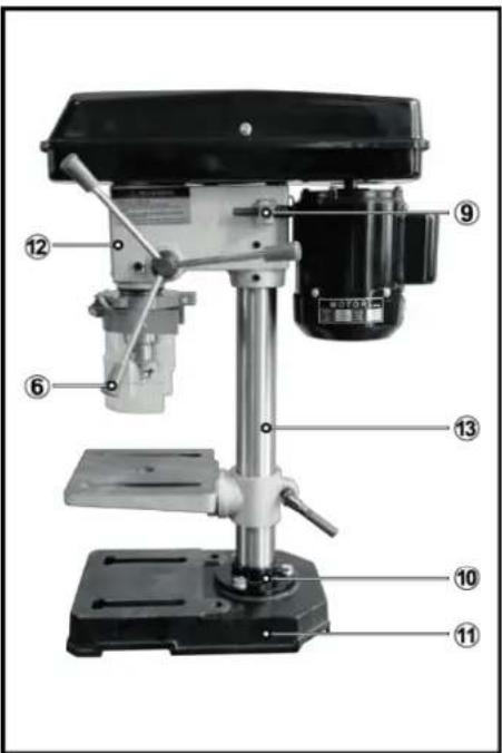
BENCH TYPE DRILL PRESS
- Pulley Cover
- Motor
- Switch
- Chuck guard
- Chuck
- Feed Handle
- Table
- Table Support
- Belt Tension Lock knob
- Column Support
- Base
- Main Housing
- Column
- Bolts
- Depth Stop Lock Nuts

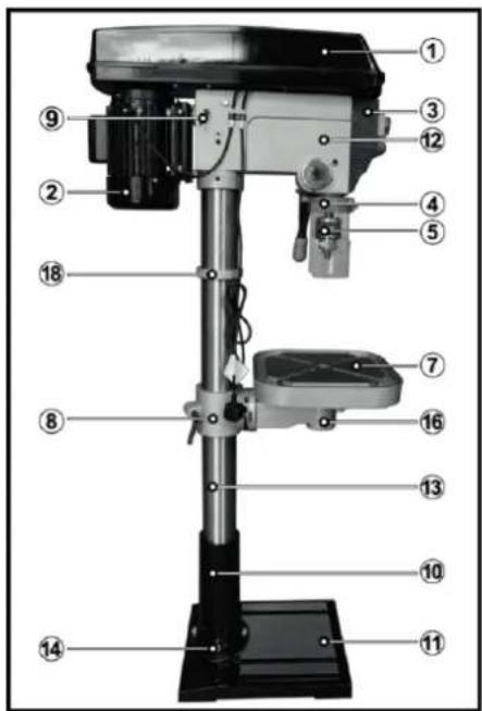
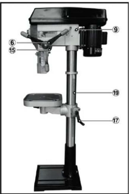
FLOOR TYPE DRILL PRESS
- Pulley Cover
- Motor
- Switch
- Chuck guard
- Chuck
- Feed Handle
- Table
- Table Support
- Belt Tension Lock knob
- Column Support
- Base
- Main Housing
- Column
- Bolts
- Depth Stop Lock Knob
- Table Lock
- Table Adjustment Handle
- Rack Collar
- Rack
UNPACKING
- The drill press is delivered with the components shown last page. Check the parts against the above list. Should there be any deficiencies or damage, you should contact your dealer immediately where the product was originally purchased. Do not discard the packaging until the machine is assembled. The packaging consists of cardboard and appropriately marked materials which can be sent to a re-cycling facility.
- To protect the machine parts from moisture, a protective coating of light machine oil will have been applied to the outside surfaces. Remove any excess with a paper towel.
- Take care when lifting the head assembly, considering its weight.
- Before use, the machine must be mounted, and securely bolted, to a strong, heavy workbench, of sufficient height that you will be standing upright when working.
- Ensure the work place is adequately lit, and that you will not be working in your own shadow.
ASSEMBLY

WARNING! During assembly ensure the drill press is disconnected from the power supply.
- Carefully remove contents from the packing box.
- Select a firm, level surface on which to assemble the drill press.
BASE & COLUMN
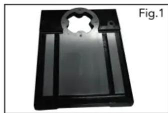
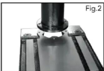
- Select the base(Fig. 1) and align the column support over the large hole (Fig. 2).
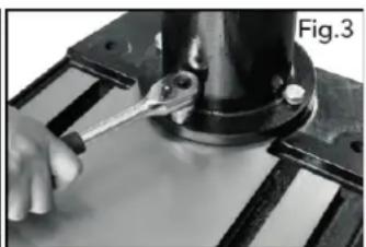
- Align the holes in the column support with those in the base and secure in place using the bolts and washers. Using a spanner securely tighten all bots(Fig. 3).
- We recommend mounting the base to stable surface for proper support.
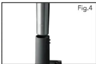
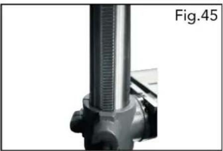
- Slide the column into the column support(Fig. 4).
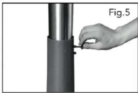
- Secure in place with 2 grub screws using the hex key (Fig. 5).
RACK & TABLE
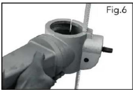
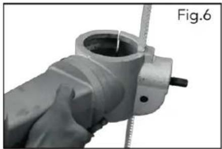
- Install the rack into the table support as shown (Fig. 6).
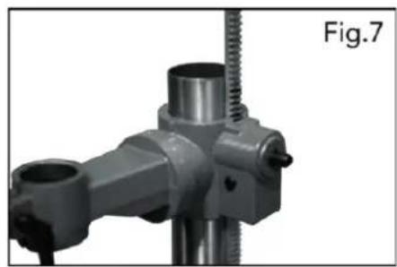
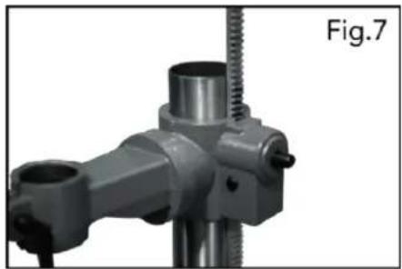
- Assemble the support and rack onto the column, ensuring the rack is positioned on the right side of the column (when viewing the product from the front) (Fig. 7).
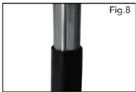
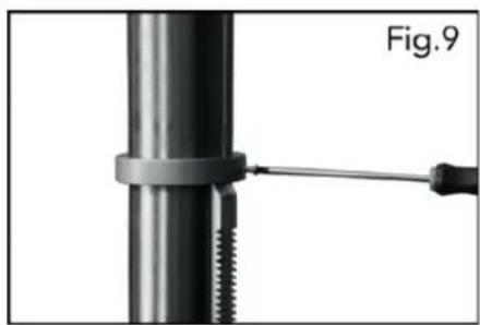
- Side the rack all the way down until locate into the lower column support (Fig. 8). Slide the collar, tapered side facing down, over the column until it locates the rack. Tighten the Philip's screw on upper collar (Fig.9).
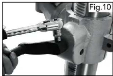
- Fix table adjustment handle on the support (Fig. 10).


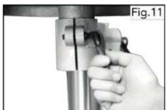
- Assemble table onto table support, tighten in place with table lock (Fig. 11).
MAIN HOUSING
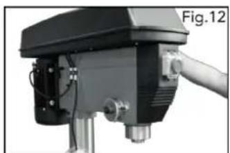
- Lift the main housing and slide it down onto the column as far as it will go (Fig. 12). Before securing the housing, ensure the spindle aligns with the table and base.
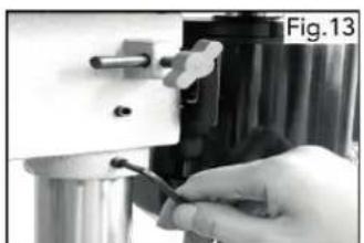
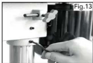
- To secure in position tighten the grub screws on the left and right hand sides of the housing (Fig. 13).
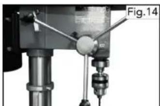
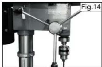
- To fit the feed wheel handles, screw them into feed wheel hub (Fig. 14).
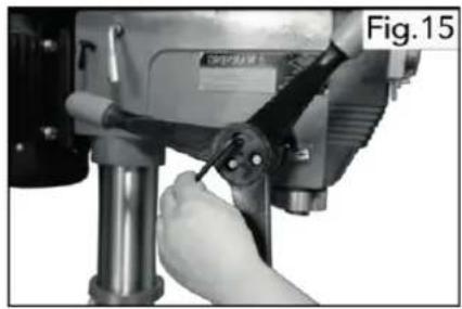
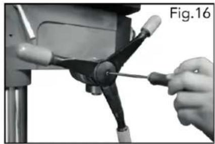
- For some cast iron feed handle, tighten the 3 grub screws to wheel hub (Fig. 15) then fix the plastic case on cast iron feed handle as shown (Fig. 16).
CHUCK & ARBOR
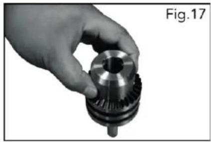
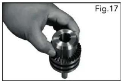
- Before any assembly, ensure the chuck jaws are wound all the way up (inside the chuck) to prevent them from damage (Fig. 17).
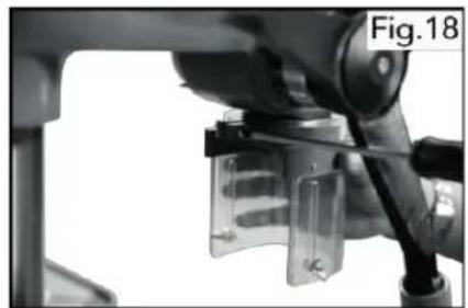
- Tighten Philip's head screws of the chuck guard to quill shaft (Fig. 18).
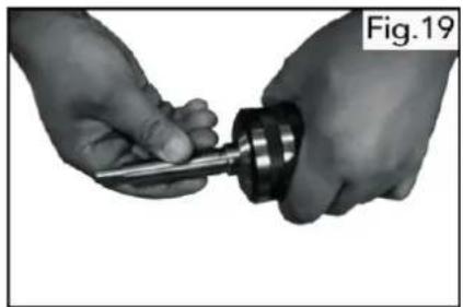
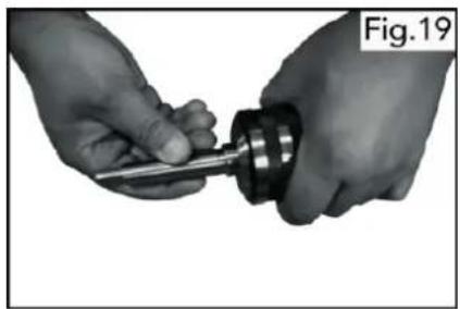
- Fit the tapered arbor end into the chuck by hand, using reasonable fore (Fig. 19).
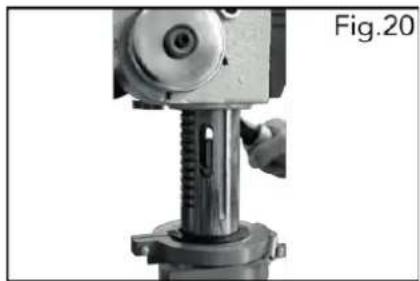
- The arbor can then be inserted into the quill, twisting the arbor as you insert, aligning the tang into the slot. It should fit in with little resistance (Fig. 20).
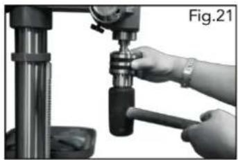
- Once it is located a firm tap on the underside of the chuck with a soft hammer is required to secure it. The chuck & arbor are installed correctly if they cannot be pulley out with hand force (Fig. 21).
7. SETTINGS AND AJUSTEMENTS

WARNING! During settings and adjustments ensure the drill press is disconnected from the power supply.
TABLE HEIGHT ADJUSTMENT
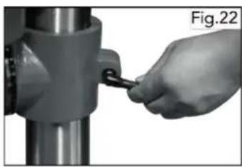
- Loosen the table support lock (Fig. 22).
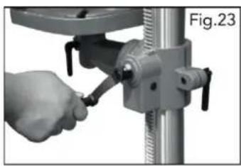
- Rotate the table adjustment handle to set the desired table height and tighten the table rock to secure the table in position (Fig. 23).
TABEL BEVEL ADJUSTMENT
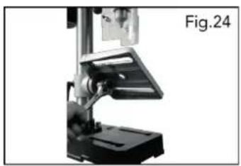
- The bevel angel is adjusted by loosening the bolt that is located underneath table support with a spanner (Fig. 24).
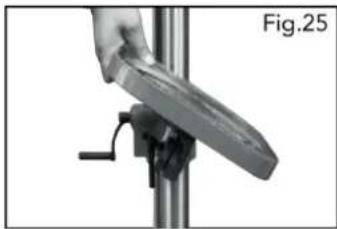
- After tilting the working table (Fig. 25) to appropriate position, re-tighten the bolt to secure its position.
CAUTION: When the table is angled/tilted, ensure the workpiece is clamped to the table.
INSTALLING STRAIGHT SHANK DRILL BITS

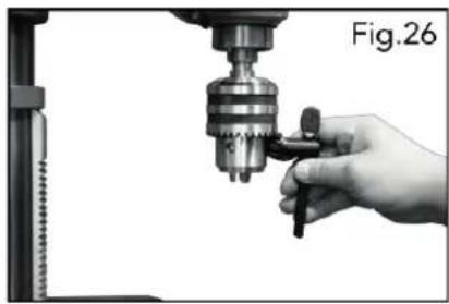
- Using the chuck key, loosen the jaws of the chuck by rotating in an anti-clockwise direction (Fig. 26).
- Insert the drill bit into the chuck (Fig. 27).
- Whilst holding the drill bit in one hand rotate the top collar of the chuck in a clockwise direction. Insert the chuck key into 1 of the 3 rotating holes and tighten until drill bit is secure (Fig. 28).


MORSE TAPER DRILL BITS

To use Morse taper bits, remove chuck and arbor.
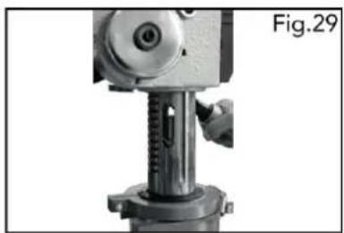
- Turn arbor until the tang aligns with the slot in the quill(Fig. 29).
- Insert the drift key into the slot and tap firmly with a metal hammer until it releases. (Ensure the chuck jaws are wound all the way up to prevent damage (Fig. 30).
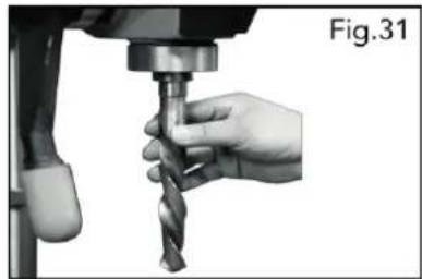
- Place tapper bit into the spindle hole, twisting and pushing upward until bit is sung (Fig. 31).
- Place block of wood on the table and raise up table until the tapered bit is firmly into the spindle.


PRE-SETTING THE DRILLING DEPTH BENCH TYPE
To set the depth of the hole, adjust the depth stop as follows:
-
Lower the chuck with the power OFF, until the drill bit touches the surface of the workpiece, and hold in that position.
-
Spin down the adjuster nut so that the gap between its underside and top of bracket is the depth of the hole required. Screw down the lock nut and lock it against the adjuster nut.
The drill is now set to drill holes to your pre-determined depth from that particular start point. i.e. Providing the surface of your workpiece is flat and level, you may drill a series of holes, each to the same depth. The scale and pointer can be used when drilling individual holes. Lower the chuck until the drill bit touches the work, set the pointer against a point on the scale, and proceed to drill to the required depth, using the scale.
FLOOR TYPE
To stop spindle (and bit) at a desired depth:
-
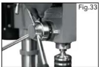
Loosen depth stop lock knob by turning in an anti-clockwise direction (Fig. 33).
-
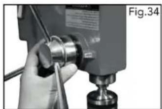
Rotate depth scale to the desired depth, then tighten half wing bolt (Fig. 34).
To hold the spindle (and bit) at a desired depth:
-
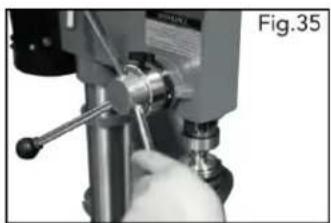
Loosen depth stop lock knob, turn feed wheel handle to lowest point (Fig. 35).
-
Rotate depth scale to desired depth and re-tighten depth stop lock knob. This will hold assembly stationery at desired depth.


CHANING THE SPEED BENCH TYPE
Before changing the seeds, ensure the machine is switched OFF, and disconnected from the power supply.
- Open the pulley cover.
- Slacken off the belt tension locking knob, to relieve any tension on the drive belt.
- Consult the chart inside the pulley cover, and position the belt on the pulley's according to the spindle speed required.
- When the belt has been correctly positioned, re-tension by levering the motor away from the head, until the belt deflects by approx. 1/2 at its centre when using reasonable thumb pressure.
Lock the motor in this position with the belt tension locking knob. - Lever the motor, with its bracket, away from the head, so that tension is applied to the belt. Tension is correct when the belt deflects by approx. 1/2 " at its centre, when using reasonable thumb pressure. Lock the motor in this position using the locking knob.
FLOOR TYPE
The speed of the drill press can be changed by adjusting the belt on the pulley system. See chart inside pulley cover for speed configurations.
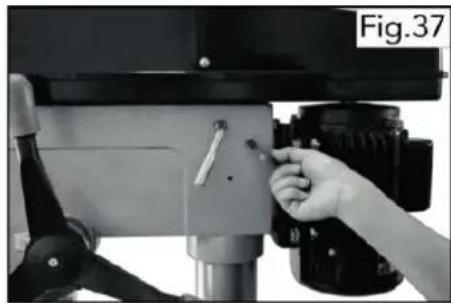
- Release the belt tension locking knobs located on either side of the main housing (Fig.37).
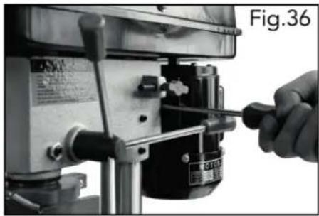

- Once the tension is released, the belt tension handle can be used to move the motor pulley closer to the idler pulley (Fig.38).
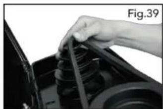
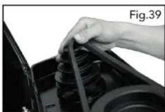
- The belt is removed by lifting it over the lip of the pulley while rotating the pulley simultaneously (Fig.39).
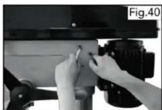
- After re-adjusting the belts, use the belt tension handle to move the motor pulley further away from the idler pulley. When the desired position is achieved use the locking knobs to secure the pulleys in place (Fig.40)
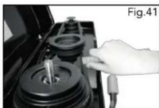
- Proper belt tension is achieved when the measured deflection (by pushing in the centre of the belt) is approx. 5mm (Fig. 41).



8. OPERATION
TURNING ON AND OFF
Note: The pulley cover must be closed to operate the drill press.
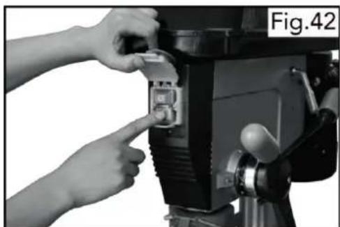
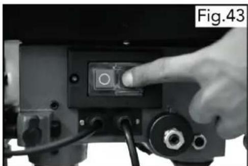
Switch the pedestal drill On by pressing the green button on the switch (Fig. 42-43).
-
Switch the drill press Off by pressing the red button on the switch.
-
Secure your workpiece to the table if possible, use a vice or clamps.
DRILLING
- Ensure the drill press is switched off and disconnected from the power supply.
- Loosen the jaws of the chuck with the chuck key by turning in an anti-clockwise direction and insert the selected drill bit into the as far as it will go.
- Insert the chuck key into 1 of the 3 locating holes and tighten until drill bit is secure.
- Select your drilling depth and secure the depth stop lock knob in position.
- Adjust the table to your desired position.
- Slowly rotate the feed wheel handles to bring the drill bit down towards the table and into your workpiece. After drilling a hole, release the feed wheel handles slowly to return the chuck to its original position.
- Continue the operation until the task is completed. When completed, switch the drill press Off by pressing the red (O) button on the switch.
9. MAINTENANCE
For maximum performance, it is essential that the Drill Press is properly maintained. Always inspect it before use. Any damage should be repaired, and faults rectified. Always remove the plug from the power supply before carrying out any adjustment, servicing or maintenance.
Please refer to the trouble shooting chart on pages down. If you are unable to rectify any faults, please contact your local dealer for assistance.
MONTHLY (IF IN REGULAR USE)
- Check tightness of mounting bolts, and head and column securing set screws.
- Check the drive belt for wear, and replace if frayed or damaged.
- Blow out with compressed air, or vacuum clean out, any dust that may have accumulated in the motor fan vents.
- Apply a thin coat of wax paste or light oil to the table and column, for lubrication, and to help prevent corrosion.
- If the mains lead is damaged in any way, it should be replaced immediately.
LUBRICATION
All bearings are packed with grease at the factory and require no further lubrication. Occasionally, lubricate the quill shaft assembly and rack with light oil if required.

AFTER USE
Remove all swarf from the machine and thoroughly clean all surfaces.
Components should be kept dry, with machined surfaces lightly oiled.
Always remove drill bits, and store in a safe place.
- TROUBLE SHOOTING
| PROBLEM | PROBABLE CAUSE | REMEDY |
| Noisy operation (under load). | a. Incorrect belt tension.b. Dry spindle.c. Loose pulley.d. Loose belt.e. Worn bearing. | a. Adjust tension.b. Remove spindle and quill assembly and lubricate.c. Tighten pulley.d. Adjust belt tension.e. Replace bearing. |
| Excessive drill wobble. | a. Loose chuck.b. Worn spindle or bearing.c. Worn chuck.d. Bent drill bit. | a. Tighten by pressing chuck down on to a block of wood against the table.b. Replace spindle shaft or bearing.c. Replace chuck.d. Renew drill bit. |
| Motor won't start. | a. Power supply.b. Motor connection.c. Switch connection faulty.d. Faulty switch.e. Motor windings burned.f. Pulley cover not closed.g. Micro switch on cover not operating.*** | a. Check power cord/fuse.b. Check motor connections.c. Check switch connections.d. Replace switch.e. Replace motor.f. Close pulley cover.g. Check operation of micro switch, and renew/adjust as necessary. |
| Drill binds in workpiece. | a. Excessive feed pressure.b. Loose belt.c. Loose drill.d. Incorrect bit speed.e. Drill angles incorrect for type of material. | a. Apply less pressure.b. Check belt tension.c. Tighten drill with key.d. Adjust the drill speed reasonably.e. Consult a technical manual dealing with materials, drills and cutting angles, and sharpen drill accordingly. |
| Drill bit burns or smokes. | a. Incorrect speed.b. Swarf is not discharging.c. Dull drill or not proper. clearance for material.d. Needs coolant.e. Excessive feed pressure | a. Refer to Cutting Speed chart & adjust drill speed accordingly.b. Clean drill.c. Check sharpness & taper.d. Use coolant whilst drilling.e. Apply less pressure. |
| Table difficult to raise. | a. Needs lubrication.b. Table lock tightened. | a. Lubricate with light oil.b. Loosen clamp. |
11. TECHNICAL SPECIFICATIONS
Model: DAZJ4113
Voltage/Frequency: 220-240 V \~ 50 Hz
Power: 350 W
Max drill capacity: 13 mm
Spindle travel: 50 mm
Column diameter: 46 mm
Table size: 160x160 mm
Base size: 300x185 mm
Model: DAZJ4116
Voltage/Frequency: 220-240 V \~ 50 Hz
Power: 550 W
Drilling capacity: 16 mm
Column diameter: 60 mm
Spindle travel: 60 mm
Table size: 200 x 200 mm
Base size: 355 X 235 mm
12. ENVIRONMENTAL PROTECTION
Power tools that are no longer usable should not be disposed of with household waste but in an environmentally friendly way. Please recycle where facilities exist. Check with your local council authority for recycling advice.
Power tools that are no longer usable should not be disposed of with household waste but in an environmentally friendly way. Please recycle where facilities exist. Check with your local council authority for recycling advice.
1. INTRODUCCION

TIPO DE TALADRO DE SUELO

DESEMPAQUE


MANDRIL Y EJE




BROCAS CONICAS MORSE


8. OPERACIÓN
ENCENDIDO Y APAGADO

PERFORACIÓN
DESPUÉS DE SU USO
DAEWOO
POWER PRODUCTS




- DRILL PRESS/TALADRO DE BANCO
- INDEX
- ÍNDICE
- IMPORTANT
- GENERAL SAFETY RULES
- CARE OF POWER TOOLS
- ADDITIONAL SAFETY RULES FOR DRILL PRESSES
- PROTECTIVE CLOTHING
- ELECTRICAL CONNECTIONS
- PRODUCT OVERVIEW
- BENCH TYPE DRILL PRESS
- FLOOR TYPE DRILL PRESS
- UNPACKING
- ASSEMBLY
- BASE & COLUMN
- RACK & TABLE
- MAIN HOUSING
- CHUCK & ARBOR
- SETTINGS AND AJUSTEMENTS
- TABLE HEIGHT ADJUSTMENT
- TABEL BEVEL ADJUSTMENT
- INSTALLING STRAIGHT SHANK DRILL BITS
- MORSE TAPER DRILL BITS
- PRE-SETTING THE DRILLING DEPTH BENCH TYPE
- FLOOR TYPE
- CHANING THE SPEED BENCH TYPE
- OPERATION
- TURNING ON AND OFF
- DRILLING
- MAINTENANCE
- MONTHLY (IF IN REGULAR USE)
- LUBRICATION
- AFTER USE
- TECHNICAL SPECIFICATIONS
- ENVIRONMENTAL PROTECTION
- INTRODUCCION
- TIPO DE TALADRO DE SUELO
- DESEMPAQUE
- MANDRIL Y EJE
- OPERACIÓN
- ENCENDIDO Y APAGADO
- PERFORACIÓN
- DESPUÉS DE SU USO
- DAEWOO
- POWER PRODUCTS
Brand : DAEWOO
Model : DAZJ4116
Category : Drill