
RPD15F - Electric motor CHAMBERLAIN - Free user manual and instructions
Find the device manual for free RPD15F CHAMBERLAIN in PDF.
| Product type | Radio tubular motor for rolling shutters and blinds |
| Brand | CHAMBERLAIN |
| Model | RPD15F |
| Diameter | 45 mm |
| Motor torque | 15 Nm |
| Rotation speed | 15 rpm |
| Supply voltage | 230 V / 50 Hz |
| Current consumption | 0.60 A |
| Power consumption | 133 W |
| Standby consumption | 1.4 W |
| Limit switch capacity | 25 turns |
| Trigger delay | 4 minutes |
| Max. PVC shutter area | 7.5 m² |
| Max. ALU shutter area | 6.0 m² |
| Max. WOOD shutter area | 3.0 m² |
| Max. awning area | 11.5 m² |
| Control type | Radio 433 MHz, 1 or 6-channel remote control |
| Main functions | Up, down, stop, programming of up to 40 remote controls |
| Safety | End-of-travel stop, thermal protection (cooling 15-20 min) |
| Kit contents | Motor, remote control, adjustment tool, wall bearing, adapter, key, manual |
| Warranty | 2 years (parts and labor) |
| Maintenance | Regular check for wear; cleaning with power off |
| Repairability | Interventions reserved for a qualified electrician |
Frequently Asked Questions - RPD15F CHAMBERLAIN
User questions about RPD15F CHAMBERLAIN
0 question about this device. Answer the ones you know or ask your own.
Ask a new question about this device
Download the instructions for your Electric motor in PDF format for free! Find your manual RPD15F - CHAMBERLAIN and take your electronic device back in hand. On this page are published all the documents necessary for the use of your device. RPD15F by CHAMBERLAIN.
USER MANUAL RPD15F CHAMBERLAIN
Tubular Motor with integrated radio RPD15F, RPD25F

Instructie -
Manager, Regulatory Affairs


BAUART GEPRUFT /TYPE APPROVED

D (+49) 06838-907-100
F (+33) 03.87.95.39.28
EB (+44) 0800 317847
NL (+31) 020.684.79.78
Chamberlain GmbH
Alfred-Nobel-Str. 4
D-66793 Saarwellingen
www.chamberlain.de
info@motorlift-service.de

INSTALLATION CORRECTE
CORRECTE INSTALLATIE
-
= stop later
-
= stopt vroeger
1 Witte schroef
2 Rode schroef
Caution! Non-compliance can result in serious injury.
Any work on the electrical installation including servicing may only be performed by a qualified electrician.
Do not allow children to play with the controls.
Check shutter or sun-blind system regularly for signs of wear and damage. Damaged systems should not be used under any circumstances until such time as they have been repaired.
Observe shutter or sun-blind system carefully whilst in operation.
Switch off shutter or sun-blind system and disconnect from mains supply, if any servicing or cleaning has to be done either on the system itself or in its immediate vicinity.
Ensure that the motor is accessible after installation (DIN 18073).
Ensure sufficient room (at least 40~cm ) is left between any moving parts and nearby objects.
Ensure system cannot trap or cut persons and secure relevant parts.
Observe safety margins as stipulated in DIN EN 294.
Please consult Chamberlain product information for further details.
IMPORTANT SAFETY INSTRUCTIONS FOR THE FITTER

Caution! Non-compliance can result in serious injury. Observe EN 60 335-2-97:2000 Safety Instructions in full.

Any work on the electrical installation may only be performed by a qualified electrician.

When electrical or electronic systems and appliances are in operation, certain components are live, which can constitute a risk. Any touching of and work performed on the equipment by persons not qualified to do so or noncompliance with safety instructions can result in personal injury or damage to property.

All the standards and regulations applying to electrical installations must be observed.

Only those spare parts, tools and other equipment as have been approved by Chamberlain may be used.

Neither the manufacturer nor the supplier assumes any liability for personal injury, damage to property or consequential injury or damage occurring as a result of the use of non-approved third party products or changes made to any accessories.

Prior to performing installation work, de-activate all connections and control facilities that are not absolutely essential for operation of the given system.

Fit control facilities within sight of the product to be controlled at a height of at least 1.5m

Ensure sufficient room is left between any moving parts and nearby objects.

Torque rating and duty cycle must comply with the requirements of the product to be driven

Technical data - torque rating and duty cycle details can be found on the tubular drive's data plate.
Correct use
The RPD15F, RPD25F tubular drives are designed for the exclusive purpose of operating shutters and sun-blind systems.
They serve to open and close these systems and replace the person that is usually operating the installation.
Therefore, tubular drives may only be installed in faultless shutter- or sun-blind systems. Rough-running systems have to be repaired. Replace defective parts. This guarantees safe operation and avoids damage during opening or closing.
Any other form of usage is deemed to be incorrect. Neither the manufacturer nor the supplier assumes any liability for personal injury, damage to property or consequential injury or damage occurring as a result of the use of the control units and / or drives for purposes other than those mentioned above or due to changes made to the equipment affecting the safety of the given system.
The details stipulated in the Operating Instructions in respect of the operation and repair of the system require strict observance. Neither the manufacturer nor the supplier assumes any liability for personal injury, damage to property or consequential injury or damage occurring as a result of non-compliant actions.
In compliance with standard EN 60 335-2-97:2000, the cable connecting the drives to the mains cable must be laid internally.
According to DIN 18073 shutter box lid must always be easily accessible and removable.
Before You Begin
- Carefully read all the information contained in this Owner's Manual before beginning installation procedures.
- Check the shutter to be sure it is not broken or damaged, and that it opens and closes smoothly.
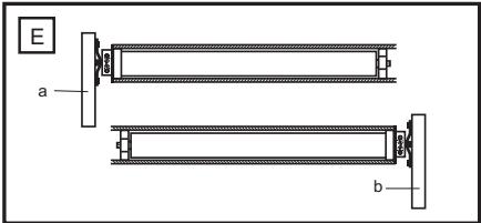
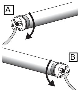
- Determine whether the motor needs to be installed on the left side (a) or the right side, (b) of the shutter – Figure . Always choose the shostest possible distance to the next junction box as wires must not be laid inside the shutter box.
- Ensure that the motor can be pushed in as far as the stop. The limit switch is controlled by the plastic ring which must be pushed fully on.
Performance Features
| Model | Diameter | Torque | Speed | Operating Voltage | Frequency | Current input | Motor rating | StandBy | Operating time | Limit Switch Range |
| (mm) | (Nm) | (rpm) | (V) | (Hz) | (A) | (W) | (W) | (min) | (U) | |
| RPD15F | 45 | 15 | 15 | 230 | 50 | 0,60 | 133 | 1,4 | 4 | 25 |
| RPD25F | 45 | 25 | 15 | 230 | 50 | 0,89 | 191 | 1,4 | 4 | 25 |
Max. area (area = length x breath)
| RPD15F | RPD25F | |
| PVC | 7,5m² | 10m² |
| ALU | 6,0m² | 8,0m² |
| WOOD | 3,0m² | 4,2m² |
| AWNING | 11,5m² |
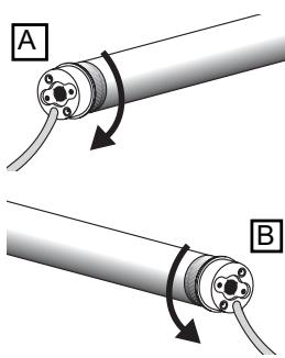
Carton Contents
Motor (1)
Adjuster pin (2)
Drive adapter safety catch (3)
Square pin (not pre-mounted) (4)
Shaft adapter (5)
Wall bracket (6)
Manual
Remote Control and Wall Clip
INSTALLATION PROCESS SEQUENCE AND STEPS
- INSTALL DRIVE (INSTALLATION)
- WIRE UP AND CONNECT DRIVE (MOTOR CONNECTION)
- SET LIMITS OF SHUTTER (THE REMOTE CONTROL HAS ALREADY BEEN PROGRAMMED).
PLEASE NOTE: SHOULD THE UP / DOWN BUTTON FUNCTION THE WRONG WAY ROUND I.E. AS DOWN / UP BUTTON, WAIT UNTIL STEP 5 BEFORE CHANGING IT! - INSERT SHUTTER ARMOURING (SLATS) AND COMPLETE INSTALLATION.
- CHANGE FUNCTIONALITY OF REMOTE CONTROL (REVERSE DIRECTION OF MOVEMENT (UP / DOWN) ON THE REMOTE CONTROL AND PROGRAMME NEW REMOTE CONTROLS).
INSTALLATION
Rough- in or install conduit pipe to the connector box for the electrical connecting line according to local building and electrical codes.
THE DRIVE IS PREMOUNTED. THE DESCRIPTION IS FOR CHECKING PURPOSES!

Place the tube drive adapter (6) on the motor and fix the drive adapter with the parts (3).
Fix the square pin with the screws on the motor (4 or 5).

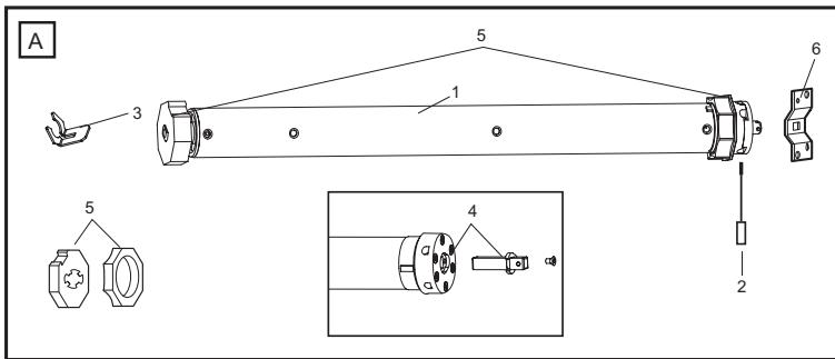
Fully unroll the shutter (a). Remove the shutter material from the tube (b). Remove the manual control (c).

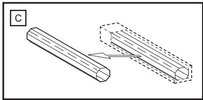
Remove the tube.

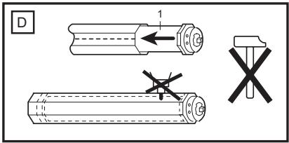
Push the motor (1) completely into the tube. The limit switch operates only if the drive unit is fully inserted. Ensure that the adapter ring is pushed fully home. Do not force it or strike it. Do not damage the tubular motor by drilling!

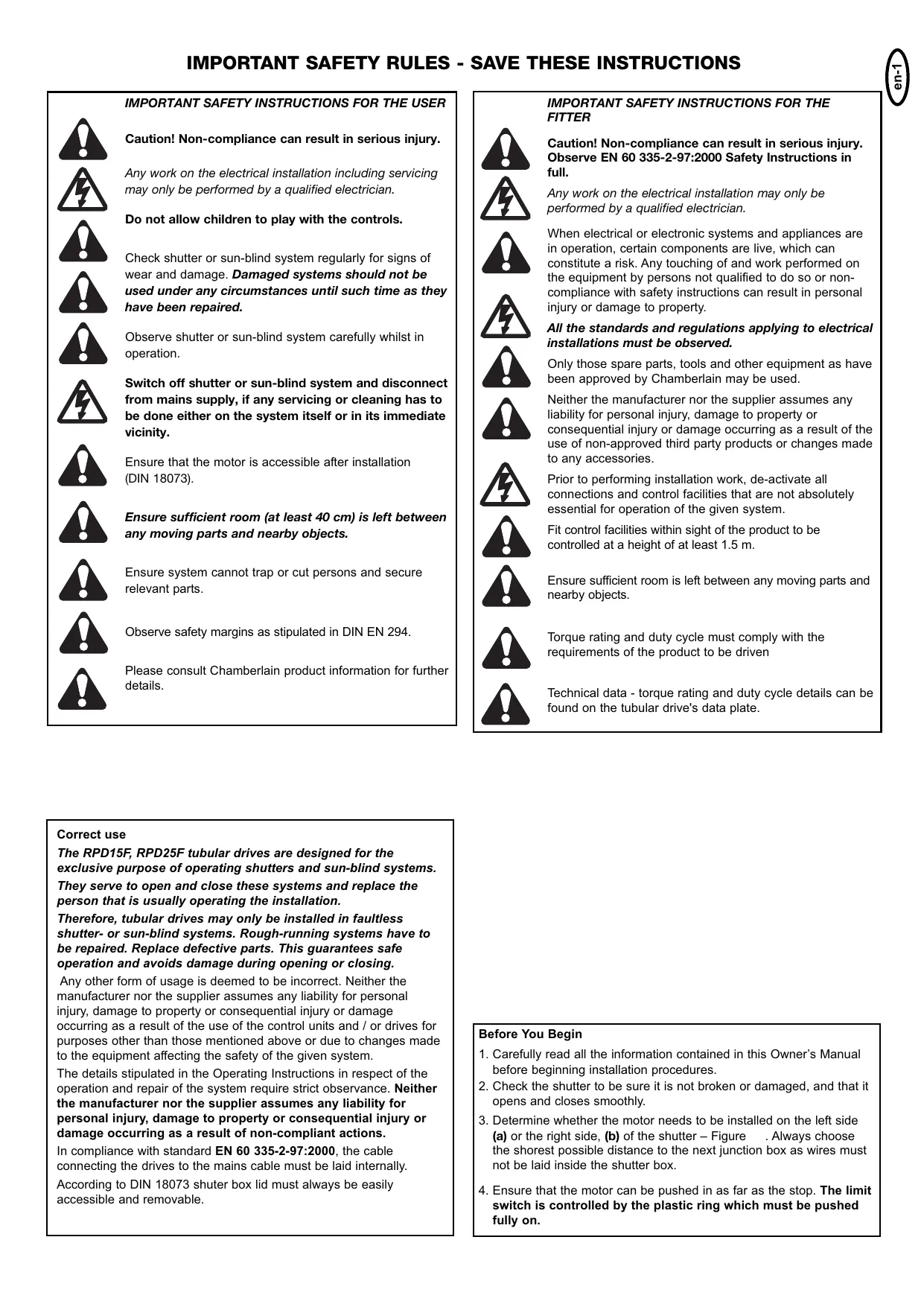
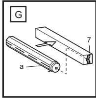
Proceed according to the specific requirements for left-sided (a) or right-sided (b) operation:

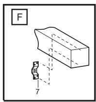
Secure the mounting bracket (7) to the wall (use suitable screws and plugs).

Insert the motor (a) into the mounting bracket (7) and secure it.
Make sure the set screws for the limit adjustments are accessible. Don't return the shutter material to the tube yet!
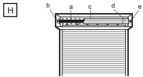
Correct Installation
The illustration H also shows the wall bracket on the drive side (b), the motor (a); the steel tube (c); the end cap (d); and the opposite wall bearing (e).
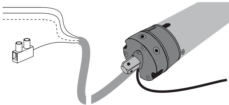
2. Wiring
DEFAULT SETTING
The limits of the shutter motor have been set to a short length of travel (small window) and must be merely adjusted to suit actual requirements.
See under Point 3: Setting the limits
The radio remote control (hand-held transmitter) has already been programmed at the factory. Should it operate in the reverse direction i.e. button for upward direction moves shutter downwards, this can be remedied.
See under: Programming first radio remote control.
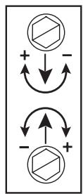
3. Setting the limits "Open" and "Closed" position
-
= stops later
-
= stops earlier
My roller shutter box is:
A: A left-handed installation. I look into the box and the limit switch of the motor is on the left (see Fig. L1)
White = Limit switch AT BOTTOM
Red = Limit switch AT TOP
B: A right-handed installation. I look into the box and the limit switch of the motor is on the right (see Fig. L2)
Red = Limit switch AT BOTTOM
White = Limit switch AT TOP
The bottom adjusting screw is always for the upper limit and the upper is always for the lower limit, no matter whether the motor is pushed into the shaft from the right or the left.
PLEASE READ THROUGH THE FOLLOWING INSTRUCTIONS CAREFULLY BEFORE SETTING THE LIMITS.
Press the DOWN / UP button (remote control or switch) and let the shutter drive move in a downward direction until it cuts off automatically and then (and only then!) ....
4. FASTEN SHUTTER ARMOURING (SLATS) TO SHAFT.
Limit at bottom is now set. If necessary make final adjustment with adjustment screw.
Allow drive to run upwards. If it switches off too early the bottom adjusting screw must be adjusted in the plus direction. Each full turn of this screw extends the travel path by about 40^ of one turn of the motor. The motor should stop just a few inches below the window frame. If not the adjusting screw should be adjusted in the minus direction. After this the drive must be driven back a little and then up again to check the result.
It is possible that the drive will switch itself off after several trips because it has reached a temperature which is too high. However after 15 - 20 minutes cooling time it will be ready to operate again.
Please note that the limit switches of the drive only function properly if the drive has been installed correctly and is completely within the shaft.
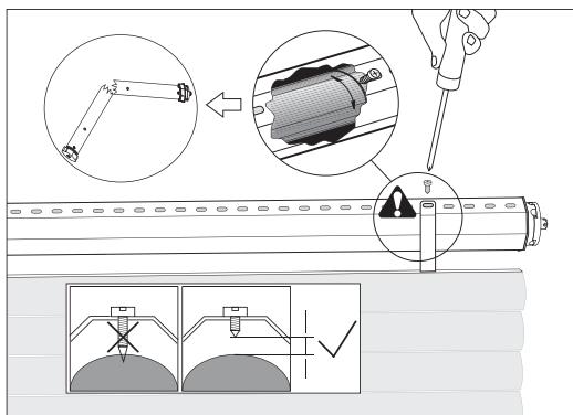
Advice: In order to fix the roller shutter hangers to the shaft, ONLY use short fixing screws. If the screws are too long damage may occur to the motor. The recommended fixing method for the hangers is without screws by means of spring band loops (which are hooked on).
5. FUNCTIONALITY OF REMOTE CONTROL
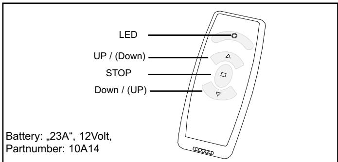
The upper button on the remote control is normally for the UP direction (open). The lower button on the remote control is normally for the DOWN direction (close). The middle button stops the shutter in any position as required (stop).
If, during an upward or downward movement, the button for the reverse direction is pressed, the motor automatically changes the direction of travel.
WALL BRACKET (HOLDER):
Supplied as standard with each 1-channel and 6-channel remote control (without screws and rawplugs).
Caution! Make sure no electric cables are damaged when fitting the bracket, particularly when installation is to occur near light switches or power sockets. The installation site should be examined carefully beforehand.
PROGRAMMING RADIO REMOTE CONTROLS (HAND-HELD TRANSMITTERS)
Up to 40x remote controls can be memorised. The first remote control programmed is also called the "master" remote control.
PROGRAMMING A NEW, ADDITIONAL REMOTE CONTROL (not the first one or so-called master)
PLEASE NOTE: The following steps must be executed quickly. Read through all the steps first. The easiest way is for a second person to help by reading out the text while the other person presses the buttons.
Step 1: The shutter should not be located at its limit. Via the master remote control:
Step 2: Press and hold the STOP button. The drive turns 2 × briefly as a signal indicating that the command has been understood (approx. 5 seconds). Wait until the drive stops moving!
Step 3: Then press the UP button (upper button) and also the DOWN button (lower button) immediately and briefly. Once again the drive moves 2x briefly as a signal that the command has been understood.
Via the new remote control:
Step 4: Press and hold the UP button (upper button) on the new remote control immediately. Once again the drive moves 2 × briefly as a signal that the command has been understood.
End of process
IMPORTANT NOTES
Note 1: Between Step 2 and Step 3 only max. 2 seconds are allowed as otherwise the process will be stopped. However, the drive must have halted beforehand.
Note 2: Between Step 3 and Step 4 only max. 7 seconds are allowed.
Note 3: Don't press a new button before the LED on the remote control has gone out and the drive has stopped moving. Should the drive run in one direction for a long time rather than a short time (between Step 2 and Step 3), the process hasn't worked. Start again from the beginning.
DELETING REMOTE CONTROLS
An individual remote control cannot be deleted. All remote controls are deleted together. Deletion is possible:
A. via the "master" remote control
B. directly via the drive (if the remote control has been lost or the battery is flat)
A. Deletion via the "master" remote control
- Disconnect the power supply to the drive (at least 10 seconds)
- Press and hold the STOP button on the "master" remote control
- Re-connect the power supply now, wait and keep pressing and holding the button.
After approx. 15 seconds the drive should turn briefly as a signal that it has understood the command.
End of process
B. Deletion "without" remote control directly via the drive
- Disconnect power supply to drive
- Connect the free black cable coming from the drive to the (L) cable.
- Re-connect power supply now and wait. The drive should turn 2x briefly and then run to one of the limit switches as a signal that the command has been understood. As soon as the drive starts turning, the remote controls are deleted.
- Disconnect power supply to drive again.
- Disconnect link to black cable making sure the free end cannot cause a short circuit.
- For further steps, see "Programming the first remote control".
End of process
PROGRAMMING THE FIRST REMOTE CONTROL REVERSING DIRECTION OF MOVEMENT
The first remote control is the "master" remote control. It also determines the direction of movement and decides whether the upper button is actually responsible for UP functionality or the opposite. Even if all that needs to be programmed is a reversal of direction of movement, all remote controls that have been programmed must still be deleted first (see Deleting with and without remote control).
PLEASE NOTE: If the reason for reprogramming was that the buttons on the remote control worked the wrong way round (DOWN/UP), press the DOWN button in the following (only applies to new drives with default programming).
- Disconnect drive from power supply
- Press and hold UP button or DOWN button (direction of movement) on the new "master" remote control (stay within radio range of drive)
- Re-connect power supply and wait
- If it has worked, the drive turns 2x briefly as a signal that the command has been understood.
End of process
Please note:
- If the process doesn't work, it could perhaps be that a "master" remote control has already been programmed. Should this not be identifiable however, everything will first have to be deleted via "Deletion without remote control".
- Were you within the reception range of the motor?
- Is the battery in the remote control in order?
- Was the period between the connection of the power supply and pressing the button on the remote control longer than 20 seconds?
ANTENNA:
The cable antenna (see Motor connection) must be accommodated in the shutter box such that it is not wound up together with the shutter. Do not wind the cable antenna around the power line (range of remote control is reduced).
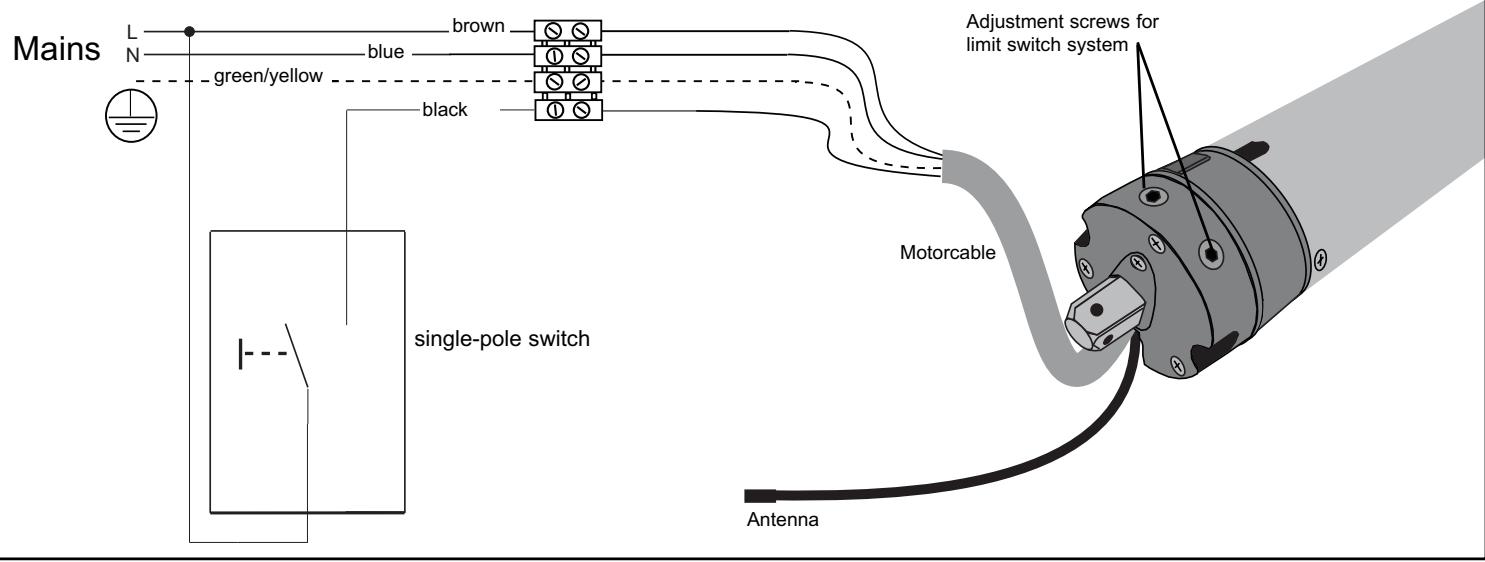
CONNECTING A WALL SWITCH (CABLE)
See drawing of motor connection for electrical connection details. A wall switch can be connected via the black cable. No special shutter switch is required for this purpose. A standard, 1-pole selector switch often used for stairways (automatic reset) is adequate. These are widely available in all shapes and sizes.
Function: The first switch pulse starts the drive, the second stops it.
The next pulse then starts the drive in the other direction, etc.
FAQs AND TROUBLESHOOTING (MOTOR)
The drive will not operate:
- Check the domestic fuses and power supply
- Has the motor been connected correctly? Check that N L L have been correctly connected.
- The limit switches have already been adjusted and both limit switches turned to the minimum. Turn both limit switches by several turns in the plus direction and test again.
- The motor became too hot and cut out. Try again after about 30 minutes cooling time.
The drive will only run in one direction:
- The drive is already at the limit switch. Adjust the limit switch or travel the motor in the other direction for several seconds so that it can travel away from the limit switch.
- Install drive. The limit switch can only function in this way.
The drive cannot find the limit switch:
- The drive is not installed. Because of this the limit switch will not turn.
- The limit switch is wrongly set. Remove the hanger and travel the motor downwards until it switches off. Then turn the limit switch for OPEN for a long time in the minus direction. Keep testing in the meantime. Then start the setting work again.
- The adapter ring on the motor, which actuates the limit switch, does not turn or is not mounted.
- Run installed motor without hanger downwards until it switches off. By briefly running upwards check whether the motor didn't possibly need a cooling break and had therefore switched itself off.
The drive is noisy and will not run:
- The clutch drive ring on the end of the motor has come off or was not plugged on.
- The motor will not turn because the roller shutter is jammed.
- The motor is not getting sufficient power because of a poor feed cable.
- Another motor is attached to the same switch. Not permitted! Only operate one switch with one motor or use an isolating relay (accessory).
- Remove locks, handles or stoppers on the roller shutter.
The domestic fuse was tripped:
- The fuse was overloaded due to the operation of several motors with isolating relays. It is necessary to have the domestic electrical system modified by a specialist.
- Incorrectly connected switch which has caused a short-circuit.
The drive is noisy:
- Close the roller shutter box.
- The drive has too much axial play (shaft). The roller shutter hanger or the shaft bearing is in poor condition and causes the noise. It is necessary to change the guide rails or the fixing on the shaft.
- Wall bracket is faulty. Special rubber dampers for wall brackets can be obtained from your specialist dealer.
The drive does not unwind neatly from the open position:
- The UP end position is too high. Set the roller shutter jacket 3-5 cm lower.
- The run-in taper at the upper end of the guide rail is not present or is bent.
- The end position of the roller shutter has changed and is higher than it should be because the jacket winds shorter.
- The guide rails are defective, they possibly require lubrication.
FAQ AND TROUBLESHOOTING (remote control)
The UP button functions as the DOWN button
- The motor turns in the opposite direction (left installation) than that set by default in the factory (right Installation). See item DELETION OF ALL REMOTE CONTROLS then PROGRAMMING THE FIRST REMOTE CONTROL
□ Programming new remote control doesn't work.
- The "master" remote control is required for this.
- The shutter drive has reached its limit position and this positive result was not immediately recognisable?
- Too far away from the drive?
See also under Range.
What sort of range can I expect?
- This is normally no problem if you are in the same room as the drive.
- No function can be guaranteed over several storeys or through walls.
Range is short
- Antenna should not be rolled up.
- Do not wind the antenna around the connection cable.
- Re-position antenna (do not extend it).
- Shutter box blocks signal. Extend antenna somewhat and allow it project out of the box (different position).
- Very close to appliances such as television, stereo unit, microwave, dishwasher or washing machine - a high level of electromagnetic radiation can be emitted, thus reducing the range.
- Battery too weak.
- If the LED is shining, the battery is normally strong enough.
- If the range has gradually diminished over weeks, the battery is weakening and should be replaced.
- As a test, you can open the shutter box and try it out with the antenna simply hanging down. If this proves successful, the antenna needs to be re-positioned as the shutter box is blocking the signals.
Range subject to severe variation/ fluctuation periodically (hourly)
- The remote control transmits on a frequency of 433MHz . If other signals are transmitted on this frequency, the range may be reduced significantly as the mixture of the signals causes the receiver in the motor to block release for safety reasons.
- Weather stations or radio-controlled temperature measuring devices transmit signals in cycles of 30-90 seconds for approx. 1 second.
- Hand-held remote controls for garage doors transmit signals briefly when the door is opened.
- Radio-operated doorbells transmit signals briefly or, if defective, often continuously. In such cases, the transmitter is located in the doorbell button.
- Headphones or other systems in households can also transmit signals via radio.
- As a test, you can deactivate the various systems and see what happens. A simple change of location often helps a lot.
- Weak battery? Replace it.
Can I operate several shutters simultaneously via a 1-channel remote control?
- This is possible in the same room, but not advisable as both or all shutters are always operated at the same time. The individual control of a single shutter is not possible. As a general rule, only use a 6-channel remote control (accessory). This is equipped with a mechanism whereby all the shutters can be automatically controlled either together or individually, as required.
| 041ADA860 TAO70EML | Adapter Achtkant 60mm, 70mm Adapter octagonal 60mm, 70mm Adaptateur octogonal 60mm, 70mm Achthoekige buisadapter 60mm, 70mm |
| TAA63EML TAA70EML TAA78EML | Adapter Nutwelle 63mm, 70mm, 78mm Adapter Awning Tube 63mm, 70mm, 78mm Adaptateur de store 63mm, 70mm, 78mm Zonnescheermadapter 63mm, 70mm, 78mm |
| TAR40EML TAR50EML TAR85EML | Adapter Rundwelle 40mm, 50mm, 85mm, Round adapter 40mm, 50mm, 85mm, Adaptateur rond 40mm, 50mm, 85mm, |
| TAF70EML | Forjas Adapter 70mm Forjas adapter 70mm Adaptateur Forjas 70mm Adapter Forjas 70mm |
| TAZ54EML TAZ64EML | ZF Adapter 54mm, 64mm Adapter ZF-tube 54mm, 64mm Adaptateur ZF 54mm, 64mm Adapter ZF 54mm, 64mm |
| TAP65EML | Adapter Profilwelle 65mm Adapter Profile tube 65mm Adaptateur tube profilé 65mm Adapter Profil 65mm |
| WT860-1 WT860-2 WT860-3 WT860-6 | Achtkantwelle 60mm - 1m, 2m, 3m, 6m Octagonal tube 60mm - 1m, 2m, 3m, 6m Axe octogonal 60mm - 1m, 2m, 3m, 6m Achthoekige buis 60mm - 1m, 2m, 3m, 6m |
| 120995 | Endkappe für Achtkantwelle 60mm Endcap for octagonal tube 60mm Embout d'axe pour axe octogonal 60mm Afsluitdop voor achthoekige buis 60mm |
| 121084 | Wandlager für Achtkantwelle 60mm Wallbearing for octagonal tube 60mm Support mural 60mm Wandplaat/muursteun 60mm |
| BMBU-D | Universallager (Abroll Funktion) Universal bracket (unroll feature) Support universal (à roulement à billes) Universele motorbeugel (afrol- functie) |
| BMBNL-D | Nachrüstlager Bracket for retrofitting Support pour motorisation ultérieure Ombouw befestiging | |
| BMB2 | Fertigkastenlager Bracket for Shutter Box Palier pour coffre tunnel Aandrijflager voor Rolluikkast | |
| 041ADW35 | Wandlager Set Wall bracket set Kit palier mural Wandlagerset | |
| RA4330 | 1-Kanal Handsender mit Wandhalterung 1-channel remote control with wall mounting Télécommande radio 1 canal avec support mural 1 kanaals afstandsbediening met muurbevestiging | |
| RA4336 | 6-Kanal Handsender mit Wandhalterung 6-channel remote control with wall mounting Télécommande radio 6 canal avec support mural 6 kanaals afstandsbediening met muurbevestiging | |
| RA7524 | Funkwandtaster mit Automatikfunktion Radio wall switch with automatic operation Poussoir mural radio avec fonction automatique Radiografische drukknop met automatische functie | |
| RA8001 | Funkempfänger External receiver Récepteur externe Externe ontvanger |
Warranty for Tubular Motor
Chamberlain GmbH warrants to the first retail purchaser of this product that the product shall be free from any defect in materials and/or workmanship for a period of 24 full months (2 years) from the date of purchase for RPD15F, RPD25F Series Models. Upon receipt of the product, the first retail purchaser is under obligation to check the product for any visible defects.
Conditions: The warranty is strictly limited to the reparation or replacement of the parts of this product which are found to be defective and does not cover the costs or risks of transportation of the defective parts or products.
This warranty does not cover non-defect damage caused by unreasonable use (including use not in complete accordance with Chamberlain's instructions for installation, operation and care; failure to provide necessary maintenance and adjustment; or any adaptations of or alterations to the products), labor charges for dismantling or reinstalling of a repaired or replaced unit or replacement batteries.
A product under warranty which is determined to be defective in materials and/or workmanship will be repaired or replaced (at Chamberlain's option) at no cost to the owner for the repair and/or replacement parts and/or product. Defective parts will be repaired or replaced with new or factory rebuilt parts at Chamberlain's option. If, during the warranty period, the product appears as though it may be defective, contact your original place of purchase.
This warranty does not affect the purchaser's statutory rights under applicable national legislation in force nor the purchaser's rights against the retailer arising from their sales purchase contract. In the absence of applicable national or EC legislation, this warranty will be the purchaser's sole and exclusive remedy, and neither Chamberlain GmbH nor its affiliates or distributors shall be liable for any incidental or consequential damages for any express or implied warranty relating to this product.
No representative or person is authorized to assume for Chamberlain GmbH any other liability in connection with the sale of this product.