
R21E - Auxiliary heating ZIBRO - Free user manual and instructions
Find the device manual for free R21E ZIBRO in PDF.


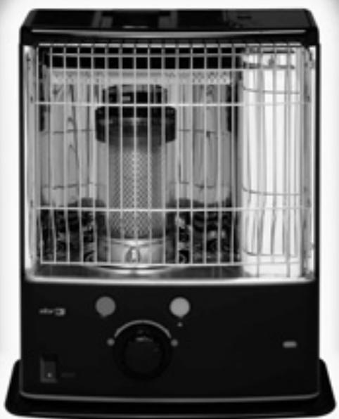
| Product type | Mobile liquid fuel auxiliary heater |
| Brand | ZIBRO |
| Model | R21E |
| Dimensions (L x D x H) | 428 x 295 x 513 mm |
| Weight | 9.0 kg |
| Power supply | 4 LR20 batteries (size D) 1.5 V |
| Fuel | Liquid fuel for mobile heating appliances (order of 8/1/1998 and 18/7/2002) |
| Recommended fuel | Zibro Extra or Zibro Kristal |
| Max heating power | 3000 W (250 g/h) |
| Removable tank capacity | 4.0 L |
| Max autonomy | Approximately 12.8 hours |
| Ignition | Electric (battery powered) |
| Wick type | F |
| Minimum room volume | 85 m³ |
| Safety | Air quality control system (E-Guard), automatic shut-off, tempered Safe Top |
| Maintenance | Cleaning fuel filter, changing batteries, wick and igniter |
| Warranty | 2 years (excluding consumables) |
| Certifications | NF 128, NF D 35-300, CE |
Frequently Asked Questions - R21E ZIBRO
User questions about R21E ZIBRO
0 question about this device. Answer the ones you know or ask your own.
Ask a new question about this device
Download the instructions for your Auxiliary heating in PDF format for free! Find your manual R21E - ZIBRO and take your electronic device back in hand. On this page are published all the documents necessary for the use of your device. R21E by ZIBRO.
USER MANUAL R21E ZIBRO
R 20 E / R 21 E / R 31 E
natural_image
Black industrial air heater with open cage and control panel (no visible text or symbols)guarantee
2
YEARS
| F | MANUEL D'UTILISATION | 2 |
| D | GEBRAUCHSANWEISUNG | 14 |
| E | INSTRUCCIONES DE USO | 26 |
| GB | OPERATING MANUAL | 38 |
| I | ISTRUZIONI D'USO | 50 |
| NL | GEBRUIKSAANWIJZING | 62 |
PAGE PLIANTE
D AUFFALTBLATT
E HOJA DESPLEGABLE
GB FOLD-OUT PAGE
PIEGHEVOLE
NL UITVOUWBLAD
AFAQ AFNOR CERTIFICATION 11, AVENUE FRANCIS DE PRESSENSE 93571 SAINT-DENIS LA PLAINE CEDEX
FICHE INFORMATIVE
Distributed in Europe by:
PVG International B.V.
P.O.Box 96, 5340 AB OSS
Distributed in Europe by:
PVG International B.V.
P.O.Box 96, 5340 AB OSS
LE COMBUSTIBLE APPROPRIÉ
natural_image
Hand holding a container with an upward arrow, labeled 'B' (no text or symbols on the diagram itself)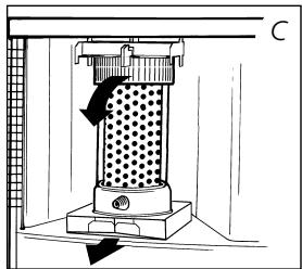
natural_image
Technical line drawing of a mechanical device with a perforated top and base, showing directional arrows (no text or symbols)
natural_image
Line drawing of a portable air purifier with a cooling fan and vent, showing no text or symbols.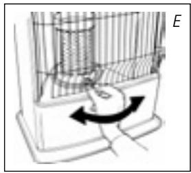
natural_image
Diagram of a birdcage with an arrow indicating rotation or movement (no text or symbols present)
natural_image
Line drawing of a hand placing a suitcase on a cart, no text or symbols present
natural_image
Line drawing of a zibro water pump connected to a battery, with no text or symbols present.A INSTALLATION DE L'APPAREIL
natural_image
Hand holding a knob with a circular dial and rotation arrow (no text or symbols)

natural_image
Diagram of a mechanical device with a hand pressing a button, showing motion direction (no text or symbols)F

natural_image
Hand holding a circular dial with an arrow indicating rotation (no text or symbols)D FONCTIONNEMENT DE L'APPAREIL
natural_image
Mechanical component diagram showing internal gear and shaft assembly with rotational arrows (no text or labels)
L'ALLUMAGE NE MARCHE PAS.
natural_image
Diagram of a mechanical device with a central component and an arrow indicating direction (no text or symbols)
natural_image
Diagram of a refrigerator interior showing a cup, fan, and door (no text or symbols)
natural_image
Line drawing of a hand inserting into a container with an arrow indicating direction (no text or symbols)
Bouchon de transport
L CONDITIONS DE GARANTIE
natural_image
Illustration of a hand using a tool to press a device on a keyboard (no text or symbols visible)
natural_image
Line drawing of a hand pressing down on a textured object with circular patterns (no text or symbols)
natural_image
Line drawing of a portable air conditioner unit with a hand adjusting its lid (no text or symbols)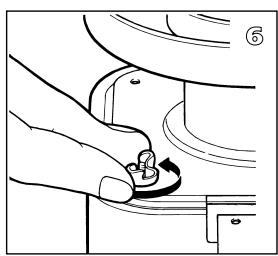
natural_image
Line drawing of a hand pressing a button on a mechanical component (no text or symbols)
natural_image
Technical line drawing of a mechanical assembly with hands operating a component (no text or symbols visible)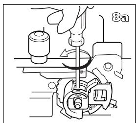


natural_image
Technical line drawing of a mechanical assembly with a hand operating a tool (no text or symbols visible)

natural_image
Mechanical assembly diagram showing a hand operating a tool with a circular component (no text or symbols visible)

natural_image
Line drawing of a hand holding a wristwatch with a circular button, no text or symbols presentLE CHANGEMENT DE LA MÈCHE
M AVANT DE COMMENCER A CHANGER LA MECHE, L'APPAREIL DOIT ETRE ETEINT ET TOTALEMENT REFROIDI.
natural_image
Illustration of a hand holding a mechanical component with a circular arrow indicating direction (no text or symbols)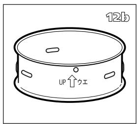
natural_image
Technical line drawing of a mechanical assembly with no visible text or symbols


natural_image
Line drawing of a hand using a tool to adjust or install a mechanical component, labeled '14d' (no text or symbols on the diagram itself)
natural_image
Line drawing of a hand holding a small object, possibly a tool or component, with no visible text or symbols.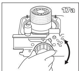

natural_image
Diagram of a hand using a tool to adjust or install a component, with an arrow indicating direction (no text or symbols present)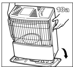


natural_image
Illustration of a 18-day industrial device with a worker operating it (no text or symbols)A DIE INSTALLATION DES KAMINOFENS

natural_image
Hand holding a container with an upward arrow, labeled 'B' (no text or symbols on the diagram itself)
natural_image
Line drawing of a portable air purifier with cooling unit and vent, showing internal components and airflow direction (no text or symbols)
natural_image
Diagram of a mechanical device with a rotating arrow and internal components (no text or symbols)

natural_image
Line drawing of a hand placing a bag onto a cart (no text or symbols)natural_image
Line drawing of a zibro water pump connected to a battery, with no visible text or symbols
D
natural_image
Diagram of a mechanical device with internal components and directional arrows indicating motion (no text or symbols)
natural_image
Hand holding a circular dial with an arrow indicating rotation (no text or symbols)
natural_image
Diagram of a mechanical or electrical component with directional arrows indicating rotation or flow (no text or symbols)natural_image
Diagram of a refrigerator interior showing a cup, fan, and door (no text or symbols)natural_image
Illustration of a hand using a tool to press a device on a keyboard (no text or symbols visible)
natural_image
Line drawing of a hand pressing down on a textured object with a circular base (no text or symbols)


natural_image
Line drawing of a portable air conditioner unit with a hand holding the lid and a scroll arrow indicating rotation (no text or symbols)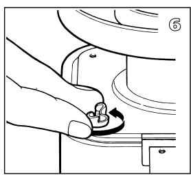
natural_image
Line drawing of a hand pressing a button on a mechanical component (no text or symbols)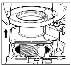
natural_image
Technical line drawing of a mechanical assembly with hands operating a component (no text or symbols visible)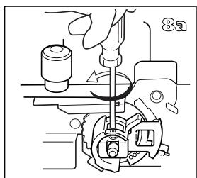


natural_image
Line drawing of a hand using a tool to adjust or install a mechanical component (no text or symbols visible)

natural_image
Mechanical assembly diagram showing a rotating component with a curved arrow indicating rotation (no text or symbols present)

natural_image
Line drawing of a hand holding a wristband with a finger pointing to the wrist area (no text or symbols)WECHSELN DES DOCHTES
natural_image
Illustration of a hand holding a mechanical component with a circular arrow indicating direction (no text or symbols)
natural_image
Technical line drawing of a mechanical assembly with no visible text or symbols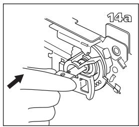


natural_image
Line drawing of a hand using a tool to adjust or install a mechanical component, labeled '14d' (no text or symbols on the diagram itself)
natural_image
Mechanical assembly diagram showing a presser pressing a component with a mesh chamber and directional arrow (no text or symbols)
natural_image
Line drawing of a hand holding a small object, possibly a tool or component, with no visible text or symbols.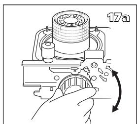

natural_image
Diagram of a hand using a tool to adjust a mechanical component, with an arrow indicating direction (no text or symbols present)


natural_image
Illustration of a 18-day industrial device with a worker operating it (no text or symbols)A INSTALACION DE LA ESTUFA
natural_image
Hand holding a container with an upward arrow, labeled 'B' (no text or symbols on the diagram itself)
natural_image
Technical line drawing of a mechanical component with directional arrows indicating movement (no text or symbols)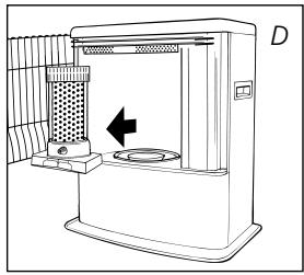
natural_image
Line drawing of a portable air purifier with a vent and control panel, no text or symbols present
natural_image
Diagram of a birdcage with an arrow indicating rotation or movement (no text or symbols present)

natural_image
Line drawing of a hand placing a bag onto a container (no text or symbols)natural_image
Line drawing of a zibro water pump connected to a battery, with no visible text or symbols
natural_image
Diagram of a mechanical or electrical component with directional arrows indicating motion (no text or symbols)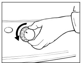
natural_image
Hand holding a circular dial with an arrow indicating rotation (no text or symbols)
natural_image
Mechanical component diagram showing internal gear and shaft assembly with rotational arrows (no text or labels)natural_image
Diagram of a mechanical device with a central component and an arrow indicating direction (no text or symbols)

Tapón de transporte
natural_image
Illustration of a hand using a tool to press a device on a keyboard (no text or symbols visible)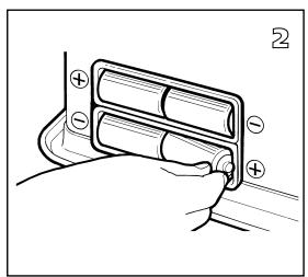

natural_image
Line drawing of a hand pressing down on a textured object with circular patterns (no text or symbols)

natural_image
Line drawing of a portable air conditioner unit with a hand adjusting its lid (no text or symbols)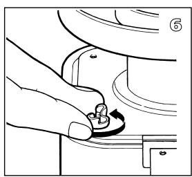
natural_image
Line drawing of a hand pressing a button on a mechanical component (no text or symbols)
natural_image
Technical line drawing of a mechanical assembly with hands operating a component (no text or symbols visible)

natural_image
Technical line drawing of a mechanical assembly with a hand operating a tool (no text or symbols visible)
natural_image
Mechanical assembly diagram showing a rotary knob and adjustment mechanism (no text or symbols)

natural_image
Line drawing of a hand holding a mechanical component with a circular feature, no text or symbols presentCAMBIAR LA MECHA
M ANTES DE COMENZAR A CAMBIAR LA MECHA, LA ESTUFA TIENE QUE ESTAR APAGADA Y COMPLETA-MENTE FRÍA.
natural_image
Illustration of a hand holding a mechanical component with a circular arrow indicating direction (no text or symbols)
natural_image
Technical line drawing of a mechanical assembly with no visible text or symbols


natural_image
Line drawing of a hand using a tool to adjust or install a mechanical component, labeled '14d' (no text or symbols on the diagram itself)
natural_image
Mechanical assembly diagram showing a presser pressing a component with a mesh chamber and directional arrow (no text or symbols)
natural_image
Line drawing of a hand holding a small object, possibly a tool or component, with no visible text or symbols.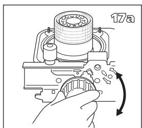

natural_image
Diagram of a hand using a tool to adjust or install a component, with an arrow indicating direction (no text or symbols present)


natural_image
Illustration of a 18-day industrial device with a worker operating it (no text or symbols)Congratulations on your purchase of this Zibro heater, the number one brand amongst portable heaters. You have purchased a first-class quality product, which will serve you for many years to come. This, of course, provided you use the heater correctly. Please read these Directions for Use first, to ensure the maximum lifetime for your Zibro heater.
This appliance comes with a 24-month manufacturer's warranty on all defects in material or workmanship.
We wish you much warmth and comfort from your Zibro heater.
Yours sincerely,
PVG International b.v.
Customer Service Department
1 READ THE DIRECTIONS FOR USE FIRST.
2 IN CASE OF ANY DOUBT, CONTACT YOUR DEALER.
3 BEFORE YOU START READING, FOLD OUT THE LAST PAGE.
GENERAL DIRECTIONS FOR USE
Below you will find the main steps to be taken for using your heater. For more details, please refer to the MANUAL (pages 41 ff.).
1 Remove all packaging materials (refer to Section A, Fig. A).
2 Fill the removable tank ⑨ and wait 30 minutes before you ignite the heater (refer to Section B, Fig. I).
3 Insert the batteries into the battery holder 13 (refer to Section A, Fig. F).
4 Check whether the combustion chamber ④ is fully upright (refer to Section A, Fig. E).
5 Ignite the heater by turning the knurled wick adjustment knob ② as far to the right as possible and then gently push the ignition button ③ (refer to Section C, Fig. J and K).
6 After igniting the heater it will take 10 to 15 minutes before you can check if the heater burns well (refer to Section D).
7 Switch off the heater (refer to Section E).
- The first time you ignite your heater it will smell like 'new' for a short time.
- Store your fuel in a cool and dark place.
- Fuel has a limited shelf life. Start every heating season with new fuel.
- The right quality of fuel will be assured, when you use Zibro Extra or Zibro Kristal for your heater.
- If you change to another brand and/or type of paraffin oil, you must first finish up all the remaining fuel in the heater.
1 OFF Button
② Knurled wick adjustment knob
③ Ignition button
4 Combustion chamber
⑤ Combustion chamber handle
6 Fuel indicator
7 Grill
⑧ Lid for removable tank
9 Removable tank
10 Fuel gauge
removable tank
11 Wick height lock
⑫ Ignition coil
13 Battery holder
14 Air quality control system
15 Information display (E-Guard)
WHAT YOU NEED TO KNOW IN ADVANCE
ALWAYS MAKE SURE THAT THERE IS SUFFICIENT VENTILATION
This heater is equipped with an air quality control system 14 . When there is insufficient ventilation in the room or when the heater is being used in a room which is too small, the heater will shut off automatically. For comfortable and safe heating ensure that there is sufficient ventilation.
Note: To avoid unexpected shut off, we recommend to put a door or window ajar when the heater is operating.
For each model the minimum size of space is specified in which you can use the heater safely, without additional ventilation (refer to Section K). If a particular room is smaller than the specified space, always leave a window or door slightly ajar ( ± 2.5 cm). We also recommend doing this in highly insulated or draught-free rooms and/or at altitudes above 1,500 metres. Do not use your heater in cellars or other underground areas.


Only the use of the correct fuel will ensure safe, efficient, and comfortable use of your heater.

SAFE TOP
The heater is supplied with a safe top. This application decreases the temperature of the top plate. In this way, the risk of harmful accidents at accidentally touching the top plate is considerably decreased. However, be aware that the top plate still becomes hot.
Avoid any contact with the top plate and grille.
THE RIGHT FUEL
Only use Class C1 paraffin fuel in accordance with BS2869 Part two, or equivalent. Your heater has been designed for use with high-quality water-free pure paraffin oil, such as Zibro Extra or Zibro Kristal. Only fuels of this kind will ensure clean and proper burning. Lower quality fuel may result in:
▶ excessive tar deposits on the glass fibre wick
▶ incomplete burning
▶ reduced heater lifetime
▶ smoke and/or smells
▶ deposits on the grid or mantle
Using the right fuel is therefore essential for safe, efficient, and comfortable use of your heater.

This transportation cap is packed separately in the box. Only this cap ensures trouble-free transportation of the heater after use. Store it well!
Always refer to your local dealer for the right fuel for your heater.

A INSTALLING THE HEATER

natural_image
Hand holding a container with an upward arrow, labeled 'B' (no text or symbols on the diagram itself)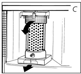

natural_image
Line drawing of a portable air purifier with a vent and control panel, no text or symbols present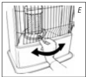
natural_image
Diagram of a mechanical device with a rotating arrow and internal components (no text or symbols)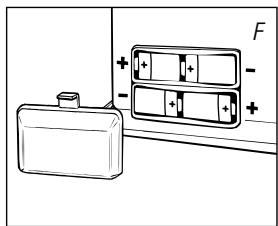
natural_image
Line drawing of a hand placing a container onto a device (no text or symbols)1 Carefully remove your heater from the box and check the contents. In addition to the heater you also need to have:
▶ a manual fuel pump
▶ a transportation cap
▶ these directions for use
Keep the box and the packaging materials (Fig. A) for storage and/or transportation.
2 Remove the other packaging materials:
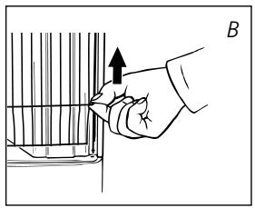
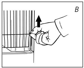
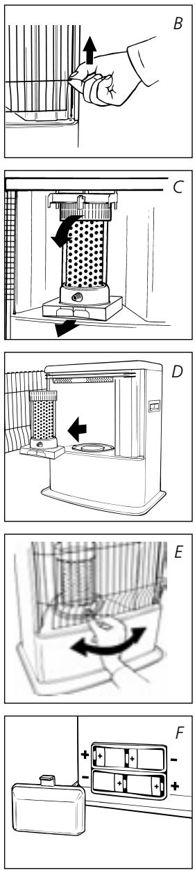
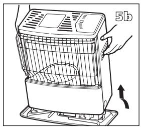
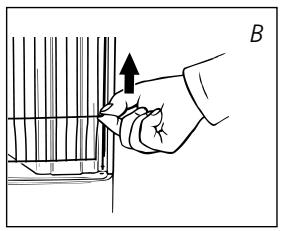
▶ Remove the packaging material from the grill ⑦. Lift the grill from the slot (Fig. B) and pull it forward.
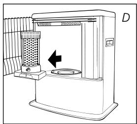
▶ Push the packing material on top of the combustion chamber ④ slightly down and remove it (Fig. C). Remove the packaging materials from under the combustion chamber as well (Fig. D).
▶ Put the combustion chamber back into its place. The combustion chamber is positioned correctly when it can be smoothly moved a little to the left and to the right by its handle ⑤ (Fig. E). Close the grill: Slightly lift it to reposition it in its slot.
▶ Open the lid of the removable tank ⑧ and remove the piece of cardboard.
3 Fill the removable tank as indicated in Section B.
4 Insert the batteries into their holder 13 at the back of the heater (Fig. F). Ensure that the positive and negative poles match the + and - marks indicated on the battery housing.
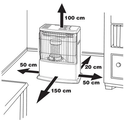
5 The floor should be firm and completely level. Reposition the heater, when it is not level. Do not correct the situation by placing books or other goods under the heater.
6 Your heater is now ready for use.
B FILLING FUEL
Do not fill the removable tank in the living room, but in a more suitable place (there can always be some spillage). Follow the procedure below:
1 Make sure that the heater is switched off.
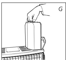
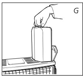
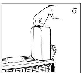
2 Open the lid ⑧ and lift the removable tank ⑨ out of the heater (Fig. G). Note: Some drops may leak from the tank. Put down the removable tank (cap pointing upwards) and screw off the fuel cap.
3 Take the manual fuel pump and insert the smooth, most rigid tube into the jerrycan. Make sure that it is in a higher position than the removable tank (Fig. H). Insert the ribbed hose into the opening of the removable tank.

natural_image
Line drawing of a zibro water pump connected to a battery, with no visible text or symbols
4 Lock the valve on top of the pump (turn clockwise).
5 Squeeze the pump a few times, until fuel starts flowing into the removable tank. As soon as this happens, there is no need to press any longer.
6 Check the removable tank fuel gauge ⑩ while filling the tank (Fig. I). Stop filling by loosening the valve on top of the pump (turn anti-clock-wise), once the gauge indicates that the tank is full. Never overfill the tank, especially not when the fuel is very cold (fuel expands when it heats up).
7 Let the remaining fuel in the pump flow back into the jerrycan and carefully remove the pump. Carefully screw the fuel cap back on the tank. Clean off any spilled fuel.
8 Check whether the fuel cap is straight and tightened properly. Reinstall the removable tank in the heater (cap down). Close the lid.
C IGNITING THE HEATER
A new heater may give off some smells for a short while, when it is used for the first time. You should therefore provide extra ventilation or ignite the heater outside the living room.

When you use the heater for the first time, first put the filled removable tank into place, and then wait approximately 30 minutes before you ignite the heater. This allows the glass fibre wick to soak up the fuel. Follow the same procedure when you have completely burnt up all fuel from the tank, and after the glass fibre wick has been replaced.
Before igniting the heater, always check the fuel indicator ⑥ to see whether the removable tank needs filling up.
Always ignite the heater with the ignition coil ⑫. Never use matches or a cigarette lighter.
Follow the procedure below:


natural_image
Hand holding a circular dial with an arrow indicating rotation (no text or symbols)
GB
1 Turn the knurled wick adjustment knob ② clockwise to its stop (Fig. J). If you apply more pressure you may turn it slightly further; however, it will automatically return to the startposition. When you have set the wick to its highest position, this action will automatically activate the safety device.
2 Push in the ignition button ③ (Fig. K), but do not apply too much force. Release the ignition button as soon as a flame is visible in the combustion chamber ④.
When you have ignited the heater but it shuts off again shortly after, the batteries need to be replaced. It is best to use new alkaline batteries (4x D-size).

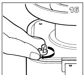
If the heater has been used only a few times and the wick adjustment knob is not locked, first turn the wick adjustment knob (Fig. L) completely left, before putting the wick in the highest position for ignition (Section C).

natural_image
Diagram of a birdcage with an arrow indicating rotation or movement (no text or symbols present)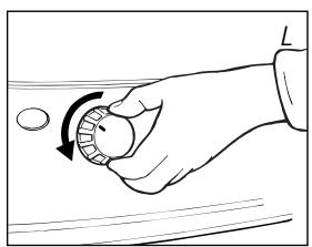
natural_image
Hand holding a circular dial with an arrow indicating rotation (no text or symbols)
After having ignited the heater, always check whether the combustion chamber ④ is level, by sliding it slightly to the left and the right by its handle ⑤ (Fig. E). This should be a smooth movement. If the combustion chamber is not level, this will cause smoke and soot to develop.
D BURNING OF THE HEATER
After you have ignited the heater, it will take 10 to 15 minutes before you can check whether the heater is burning well. Too high a flame may cause smoke and soot, whereas too low a flame causes smells. The page opposite the folding page shows the minimum and maximum permissible burning heights of the flame (Fig. R).

If the flame remains low after the adjustment, the wick height must be adjusted (refer to Section F).
Burning that is too low may be caused by:
▶ insufficient fuel (fill the tank)
▶ poor fuel quality (contact your dealer)
▶ insufficient ventilation (put window or door ajar)
▶ wastage of the wick (contact your dealer or replace the wick, refer to section M)

When there is insufficient ventilation in the room, an intermittent buzzer will be heard and the VENT lamp (Yellow) will be lit. When this signal is given, ensure that the ventilation of the room is improved (e.g. by opening a door or window a little more) to avoid that the heater shuts off. When the ventilation of the room is improved, the VENT lamp and buzzer will be deactivated. When there is still insufficient ventilation, the heater shuts off automatically. After improving the ventilation of the room (e.g. by opening a door or window a little more), the heater can be ignited again.

This heater is fitted with a safety system that ensures that it switches off if you lift the exchange tank out of the heater. To switch the heater on again, put the exchange tank back and follow the steps in chapter C.
E SWITCHING OFF THE HEATER
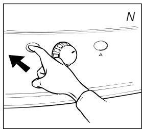
Push the OFF-button ①. The flame will extinguish after a little while.
F ADJUSTING THE WICK HEIGHT (R21E)
After a period of time the combustion may no longer be high enough (Section D). In that case you can adjust the wick height to improve the flame. To do this, the heater must have been switched off. Follow the procedure below:

natural_image
Diagram of a mechanical or electrical component with directional arrows indicating rotation or flow (no text or symbols)1 Push the OFF button ① (Fig. N).
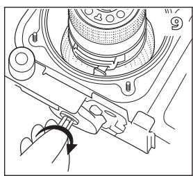
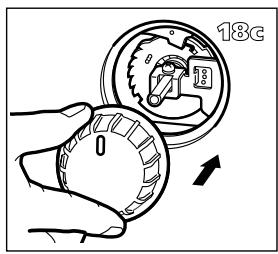
2 Pull the knurled wick adjustment knob ② off the heater, so the wick height lock ⑪ will be visible.
3 Take the plastic collar between your thumb and index finger and pull it out. Turn the collar up one step, to either position 2 or 3 (Fig. O). Carefully push the collar back, so the pin engages in the recess. GB

4 Carefully reinstall the knurled wick adjustment knob. This can be done in one way only - check the rear of the cap for the correct position.

If adjustment of the wick height does not have the required effect, let the heater burn until all fuel has been used up (Section H).
If the flame height is still too low and the wick is set on position 3, then contact your dealer, or replace the wick, refer to section M. If the flame gets too high after adjusting (Fig R), the wick height lock should be placed one position lower again. Otherwise smoke or soot may be caused.
G MALFUNCTION, CAUSES AND SOLUTIONS
If any malfunctioning cannot be solved from the directions below, please contact your dealer.
THE HEATER DOES NOT IGNITE
The batteries are not positioned correctly in the holder. Check (Fig. F).
There is not enough power left in the batteries for the ignition. Replace (Fig. F).
▶ You have run out of fuel from the tank or the wick has been replaced. After having refilled and replaced the removable tank, wait for 30 minutes before igniting the heater.
▶ You are pushing the ignition button ③ with too much force. Push it in less forcefully (Section C).
The ignition coil 12 is defective. Contact your dealer.
IRREGULAR FLAME AND/OR SOOT AND/OR SMELLS
The combustion chamber ④ has not been positioned correctly.
Use the handle ⑤ to put it level, until you can easily slide it slightly to the left and to the right and the chamber is level.
▶ You are using fuel which is past its 'use by' date. Start every heating season with fresh fuel.
▶ You are using the incorrect type of fuel.
Refer to THE RIGHT FUEL (See Section 'What you need to know in advance').
▶ Dust has gathered in the lower part of the heater.
Wick position wrong. R20E: Contact your dealer. R21E: See Section F. R31E: Contact your dealer.
THE HEATER SLOWLY EXTINGUISHES
The removable tank is empty. See Section B.
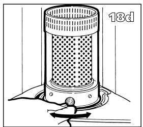
The fuel filter is contaminated by moist. Dry the fuel filter (Section H).
The lower reservoir is contaminated by moist. Contact your dealer.
The wick has hardened on the upper side.
Burn the heater until all fuel is used (Section H). Use the right fuel.
▶ You are using fuel which is past its 'use by' date. Start every heating season with fresh fuel.
THE HEATER REMAINS BURNING LOW
▶ Wick position too low.
R20E: Contact your dealer. R21E: Reinstall the wick height lock (Section F). R31E: Contact your dealer.
Before you refilled the tank, the heater had burnt up almost all the fuel. After having refilled and replaced the removable tank, wait for 30 minutes before igniting the heater.
▶ You are using the incorrect type of fuel.
Refer to THE RIGHT FUEL (See Section 'What you need to know in advance').
The room is insufficiently ventilated.
Leave a window or a door wide open for a while.
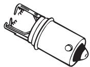
broken ignition coil
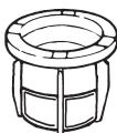
fuel filter
natural_image
Diagram of a refrigerator interior showing a cup, fan, and door (no text or symbols)
THE HEATER IS BURNING TOO HIGH
▶ You are using an incorrect, too volatile type of fuel.
Refer to THE RIGHT FUEL (See Section 'What you need to know in advance').
▶ Wick position too high.
R20E: Contact your dealer. R21E: Reinstall the wick height lock (Section F).
R31E: Contact your dealer.
H MAINTENANCE
Your heater needs hardly any maintenance. It is, however, important that you remove dust and stains in time with a damp cloth, because otherwise these may cause stains that are hard to remove. Under normal conditions, only three components are subject to wear:
1. THE BATTERIES
You may replace the batteries yourself. Do not dispose of old batteries along with the other domestic waste. Follow the locally applicable regulations regarding the disposal of domestic chemical waste.
2. THE IGNITION COIL
The ignition coil will have a longer life, if you ignite the heater in the correct manner. Replace the batteries in time and take care not to push in the ignition button with too much force. If the filament is broken, the ignition coil must be replaced.
3. THE WICK
To extend the glass fibre wick life, you must occasionally let the heater burn until the tank is completely emptied and the heater extinguishes by itself. Do this when you notice that the flame is weakening. The burn-out will cause some smells, so it is recommended that you take the heater outside of the living room.
THE FUEL FILTER
Check the fuel filter regularly as well.
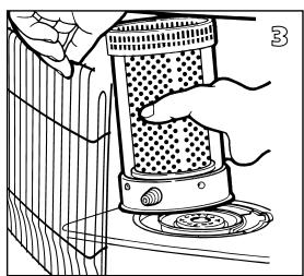
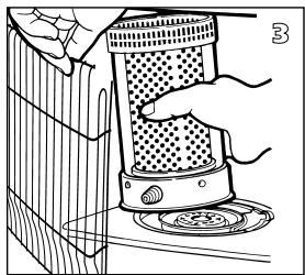
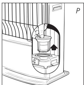
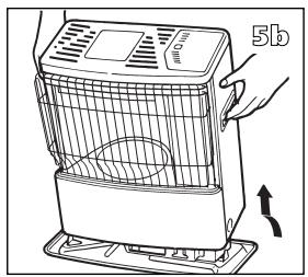
Remove the removable tank ⑨ from the heater and take out the fuel filter (Fig. P). Some drops of fuel may spill from the filter; keep a cloth at hand. Turn the fuel filter upside down and clean it from all dirt deposits by tapping it on a hard surface. (Never clean it with water!) Reposition the fuel filter in the heater.

Do not remove any heater components yourself. Always contact your dealer for repairs.

Let the heater cool down first, before you start any maintenance or service work.
I STORAGE (END OF THE HEATING SEASON)
We recommend that you burn up all the fuel in the fuel tank at the end of the heating season and store the heater properly. Follow the procedure on the next page:
1 Ignite the heater outside the living room and let it burn until all fuel is used.
2 Let the heater cool down.
3 Clean the heater with a damp cloth and then dry it with a dry cloth.

Transportation cap
4 Remove the batteries from the holder ⑬ and store them in a dry place.
5 Clean the fuel filter (refer to section H).
6 Store the heater in a dust-free place, if possible in its original packaging. Unused fuel cannot be used for the next heating season. If there is still some fuel left, do not throw it away, but dispose of it in accordance with the local regulations for the disposal of domestic chemical waste. Always start the new heating season with fresh fuel. When you start re-using the heater, follow the instructions again (starting from Section A and as specified).
J TRANSPORTATION
Take the following measures to avoid fuel leakage during the transportation of the heater:
1 Let the heater cool down.
2 Remove the removable tank ⑨ from the heater and remove the fuel filter (Fig. P). Some drops may leak from the filter; keep a cloth at hand. Store the fuel filter and the removable tank outside the heater.
3 Place the transportation cap into the position of the fuel filter (Fig. Q). Press it tight.
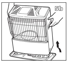
4 Always move the heater in an upright position.
K SPECIFICATIONS
| R20E / R21E / R31E | |
| Ignition | electrical |
| Fuel | paraffin |
| Capacity (kW)* | 2.85 / 3.00 / 2.90 |
| Suitable space (m3)** | 80-105 / 85-110 / 80-105 |
| Fuel consumption (l/hr)* | 0.297 / 0.313 / 0.303 |
| Fuel consumption (g/hr)* | 237.5 / 250 / 242 |
| Burning time per tank (hr)* | 13.5 / 12.8 / 13.2 |
| Capacity removable tank (litres) | 4.0 |
| Weight (kg) | 9.0 |
| Dimensions (mm) | width | 428 |
| (including base plate) | depth | 295 |
| height | 513 | |
| Accessories: | manual fuel pump transportation cap | |
| Required batteries | 4x LR20, MN 1300 | |
| 1.5V, size D | ||
| Wick type | F | |
* At maximum setting
** Specified values are indicative
L WARRANTY PROVISIONS
Your heater comes with a 24-month warranty starting on the date of purchase. Within this period all defects in material or workmanship will be repaired without any charge. The following provisions shall apply regarding this warranty:
1 We expressly dismiss all other claims for damages, including consequential damages.

2 Any repairs or replacements of components within the term of warranty will not result in an extension of the term of warranty.
3 The warranty will no longer apply, when the heater has been modified, non-original parts have been used, or when it is repaired by third parties.
4 The warranty will not apply to parts that are subject to normal wear, such as the batteries, the ignition coil, the wick and the manual fuel pump.
5 The warranty will only apply, when you present the original, dated proof of purchase, provided no changes have been made to it.
6 The warranty will not apply to damages caused by actions not in compliance with the Directions for Use, neglect, and the use of an incorrect type of fuel, or fuel past its use-by date. The use of incorrect fuel can even be dangerous*.
7 Transportation costs and the risks involved during the transportation of the heater or heater components will always be the responsibility of the purchaser.
In order to avoid unnecessary costs, we recommend that you always read the 'Directions for Use' carefully first. In case they offer no solution, please take the heater to your dealer for repair.
* Highly inflammable substances may induce uncontrollable burning, causing flames to break out. Should this happen, never try to move the heater, but always switch off the heater immediately (refer to Section E). In cases of emergency you may use a fire extinguisher, but only a type B extinguisher: a carbon dioxide or powder extinguisher.
10 TIPS FOR SAFE USE
1 Make sure that children are always aware of the presence of a burning heater.
2 Do not move the heater when it is burning or still hot. Do not refill nor service the heater when it is burning or still hot.
3 Position the front of the heater at a minimum distance of 1.5 metres from walls, curtains, and furniture.
4 Do not use the heater in dusty rooms or in very draughty places. In both cases you will not have optimum burning.
5 Switch off the heater, before you go to sleep.
6 Store and move fuel only in suitable tanks and jerrycans.
7 Make sure that the fuel is not exposed to heat or extreme temperature changes. Always store the fuel in a cool, dry and dark place (sunlight will affect the quality).
8 Never use the heater in places where harmful gasses or fumes may be present (e.g. exhaust gasses or paint fumes).
9 Be aware that the grid of the heater becomes hot. If the appliance is covered there is a risk of fire.
10 Always make sure that there is sufficient ventilation.

natural_image
Illustration of a hand using a tool to press a device on a keyboard (no text or symbols visible)

natural_image
Line drawing of a hand pressing down on a textured object with a circular base (no text or symbols)

natural_image
Line drawing of a portable air conditioner unit with a hand adjusting its lid (no text or symbols)
natural_image
Line drawing of a hand pressing a button on a mechanical component (no text or symbols)
natural_image
Technical line drawing of a mechanical assembly with hands operating a component (no text or symbols visible)

natural_image
Line drawing of a hand using a tool to adjust or install a mechanical component (no text or symbols visible)
natural_image
Mechanical assembly diagram showing a rotating component with a curved arrow indicating rotation (no text or symbols present)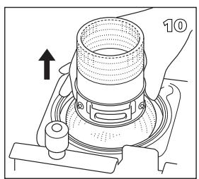

natural_image
Line drawing of a hand holding a wristband with a finger pointing to the wrist area (no text or symbols)REPLACEMENT OF THE WICK
M ENSURE THAT THE HEATER IS OFF AND COMPLETELY COOL BEFORE STARTING TO REPLACE THE WICK.
1 Open the lid and remove the removable tank.
2 Remove the batteries from the battery holder.
3 Open the front grill. Remove the combustion chamber from the heater. Close the grill.
4 Pull the knurled wick adjustment knob off the heater (wick height lock: R21E).
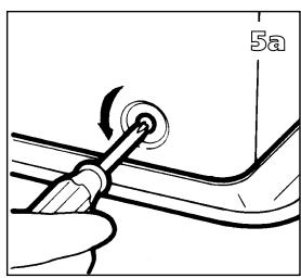
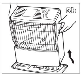
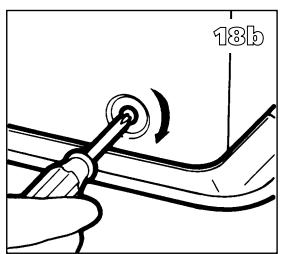
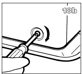
5 Unscrew the three cabinet screws on the back and sides of the heater. Pull the cabinet forward slightly, and then remove it from the base plate.
6 Unscrew the four wing nuts from the wick holder.
7 Lift up the wick holder and the wick mechanism.
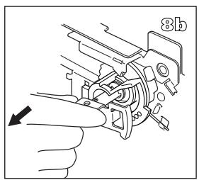
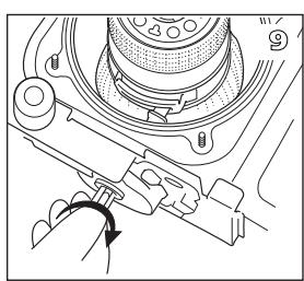
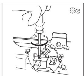
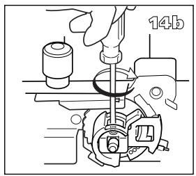
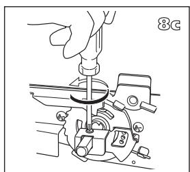
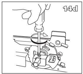
8 Remove the screw on the stem holding the bracket and remove the bracket, spring and wick height lock (R21E). Remove the screw on the stem holding the bracket and remove the bracket (R20E/R31E).
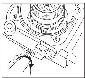
9 Turn right the stem to the end and remove the wick sleeve (with wick).
10 Lift the wick sleeve up and remove it from the primary air tube.
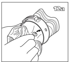
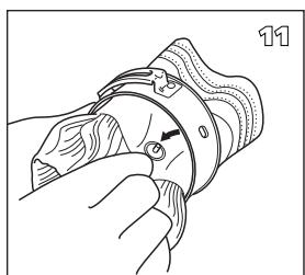
11 Squeeze the wick to loosen the three wick pins and remove the wick from the wick sleeve. Ensure that you are wearing gloves and that you have a container in which to put the old wick.
natural_image
Illustration of a hand holding a mechanical component with a circular arrow indicating direction (no text or symbols)
natural_image
Technical line drawing of a mechanical assembly with no visible text or symbols


natural_image
Line drawing of a hand using a tool to adjust or install a mechanical component, labeled '14d' (no text or symbols on the diagram itself)
natural_image
Technical diagram of a mechanical assembly with a component labeled '15' and an arrow indicating direction (no readable text or symbols beyond label)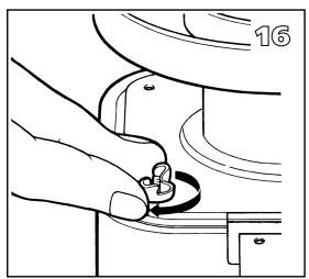
natural_image
Line drawing of a hand holding a small mechanical component, no text or symbols present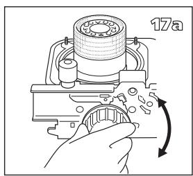

natural_image
Line drawing of a hand using a tool to adjust or install a component, with no visible text or symbols.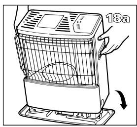


natural_image
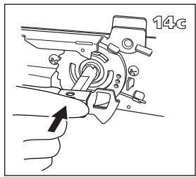
Line drawing of a 18-day industrial device with a perforated top and base, no text or symbols present12 Install the wick to the wick sleeve according to the allowed direction engraved on the wick sleeve.
13 Install the wick sleeve (with wick) to the primary air tube. And then install the top of the stem into the groove of the wick sleeve (with wick) from right side, and left the stem to the end.
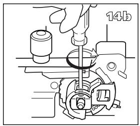
14 Install the wick height lock (the wick position should be adjusted at No. 1), spring and bracket (R21E). Install the bracket (R20E/31E). Then tighten the screw which is holding the stem.
15 Put the wick holder chassis back into position.
16 Screw the four wing nuts hand tight.
17 Place the knurled wick adjustment knob on the wick mechanism. Turn the knob as far to the right as possible. Press the tip-over switch. Check that the wick can be lowered completely. Repeat this check a number of times. If the wick cannot be lowered completely it has not been placed correctly. If this is the case, repeat the procedure from No. 12. Pull the knurled wick adjustment knob off the heater.
18 Put the cabinet back into position and tighten the three screws. Put the knurled wick adjustment knob back into position. Now put the combustion chamber back into position. Check that it is level by sliding it slightly to the left and the right by its handle. Close the grill.
19 Put the filled removable tank into position. Put the batteries into the battery holder (ensure that the positive and negative poles match the + and – marks indicated on the battery housing). Wait 30 minutes after replacing the tank and batteries before using the heater.


Egregio Signore, Gentile Signora,

natural_image
Line drawing of a hand placing a small object onto a container (no text or symbols)natural_image
Line drawing of a zibro water pump connected to a battery, with no visible text or symbols
C ACCENSIONE DELLA STUFA
1
natural_image
Diagram of a birdcage with an arrow indicating rotation or movement (no text or symbols)
natural_image
Hand holding a circular dial with an arrow indicating rotation (no text or symbols)
D LA COMBUSTIONE DELLA STUFA
natural_image
Hand holding a knob with an arrow pointing to it, against a background with a letter 'N' and small circles (no text or symbols on the knob itself)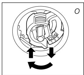
natural_image
Mechanical component diagram showing internal gear and shaft assembly with rotational arrows (no text or labels)
natural_image
Technical line drawing of a mechanical device with a component and directional arrow (no text or symbols)
2. LA RESISTENZA DI ACCENSIONE
natural_image
Illustration of a hand using a tool to press a device on a keyboard (no text or symbols visible)

natural_image
Line drawing of a hand pressing down on a textured object with a circular base (no text or symbols)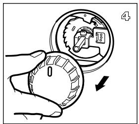

natural_image
Line drawing of a portable air conditioner unit with a hand holding the lid and a scroll wheel, showing no text or symbols.
natural_image
Line drawing of a hand pressing a button on a mechanical component (no text or symbols)
natural_image
Technical line drawing of a mechanical assembly with hands and a component, no visible text or symbols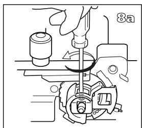


natural_image
Line drawing of a hand using a tool to adjust or install a mechanical component (no text or symbols visible)
natural_image
Mechanical assembly diagram showing a rotating component with a curved arrow indicating rotation (no text or symbols present)
natural_image
Line drawing of a hand holding a wristband with a finger pointing to the wrist area (no text or symbols)natural_image
Illustration of a hand holding a mechanical component with a circular arrow indicating direction (no text or symbols)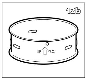
natural_image
Technical line drawing of a mechanical assembly with no visible text or symbols


natural_image
Line drawing of a hand using a tool to adjust or install a mechanical component, labeled '14d' (no text or symbols on the diagram itself)
natural_image
Mechanical assembly diagram showing a presser pressing a component with a mesh chamber and directional arrow (no text or symbols)
natural_image
Line drawing of a hand holding a small object, possibly a tool or component, with no visible text or symbols.

natural_image
Diagram of a hand using a tool to adjust or install a component, with an arrow indicating direction (no text or symbols present)


natural_image
Line drawing of a 18-day industrial device with a perforated top and base, no text or symbols presentWAT U VOORAF MOET WETEN
ALTIJD VOLDOENDE VENTILEREN
A HET INSTALLEREN VAN DE KACHEL
natural_image
Hand holding a vertical object with an upward arrow, labeled 'B' (no text or symbols on the object itself)
natural_image
Technical diagram of a mechanical device with a perforated column and directional arrows indicating motion (no text or symbols)
natural_image
Line drawing of a portable air purifier with a cooling fan and vent, showing no text or symbols.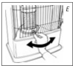
natural_image
Diagram of a mechanical device with internal components and directional arrow (no text or symbols)
natural_image
Line drawing of a hand placing a bag onto a tray (no text or symbols)natural_image
Line drawing of a zibro water pump connected to a battery via tubing (no text or symbols)
natural_image
Diagram of a birdcage cage with an arrow indicating rotation or movement (no text or symbols)
natural_image
Hand holding a circular dial with an arrow indicating rotation (no text or symbols)
natural_image
Hand pointing at a surface with a compass rose and a small circle labeled 'N' (no text or symbols on the hand or surface)E HET UITZETTEN VAN DE KACHEL
natural_image
Mechanical diagram showing a rotating component with directional arrows indicating motion (no text or labels)F HET VERSTELLEN VAN DE KOUSHOOGTE (R21E)
natural_image
Diagram of a device with a container and arrow indicating direction, no text or symbols present
natural_image
Technical line drawing of a mechanical device with internal components and an arrow indicating direction (no text or symbols)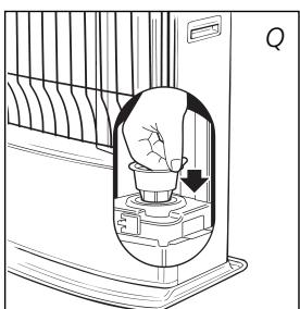
natural_image
Diagram of a light bulb inside a fan-shaped container with a handle, showing airflow direction (no text or symbols)
Transportdop

I OPSLAG (EINDE STOOKSEIZOEN)
natural_image
Illustration of a hand using a tool to press a device on a keyboard (no text or symbols visible)

natural_image
Line drawing of a hand pressing down on a textured object with circular patterns (no text or symbols)

natural_image
Line drawing of a portable air conditioner unit with a hand adjusting its lid (no text or symbols)
natural_image
Line drawing of a hand pressing a button on a mechanical component (no text or symbols)
natural_image
Technical line drawing of a mechanical assembly with hands operating a component (no text or symbols visible)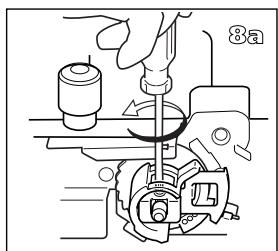

natural_image
Technical line drawing of a mechanical assembly with a hand operating a tool (no text or symbols visible)

natural_image
Mechanical assembly diagram showing a hand operating a tool with a circular component (no text or symbols visible)

natural_image
Line drawing of a hand holding a wristwatch with a circular button, no text or symbols presentHET VERVANGEN VAN DE KOUS
M VOORDAT U BEGINT MET HET VERVANGEN VAN DE KOUS, DIENT DE KACHEL UIT EN VOLLEDIG AFGEKOELD TE ZIJN.
natural_image
Illustration of a hand holding a mechanical component with a circular arrow indicating direction (no text or symbols)
natural_image
Technical line drawing of a mechanical assembly with no visible text or symbols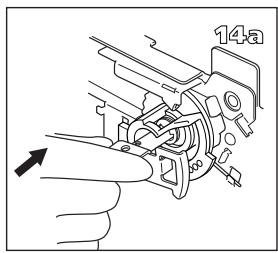

natural_image
Line drawing of a hand using a tool to adjust or install a mechanical component, labeled '14d' (no text or symbols on the diagram itself)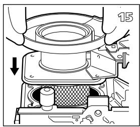
natural_image
Technical diagram of a mechanical assembly with a component labeled '15' and an arrow indicating direction (no readable text or symbols beyond label)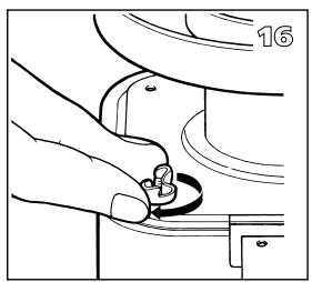
natural_image
Illustration of a hand holding a small mechanical component, no text or symbols present

natural_image
Diagram of a hand using a tool to adjust or install a component, with an arrow indicating direction (no text or symbols present)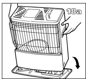


natural_image
Line drawing of a 18-day industrial device with a perforated top and base, no text or symbols presentnatural_image
3D rendering of a cylindrical industrial fan or filter unit with hexagonal lattice structure and mounting base (no text or symbols)

natural_image
Illustration of a cylindrical industrial exhaust fan with perforated internal structure and a cross symbol (no text or labels)◀ R


DISTRIBUTED IN EUROPE BY PVG INTERNATIONAL b.v.
A ÖSTERREICH
Holloway Bank, Wednesbury
West Midlands WS10 OAW
tel.: +44 121 506 1818
fax: +44 121 505 1744
email: gases@lister.co.uk
ITALIA
PVG Italy SRL
Via Niccolò Copernico 5
50051 CASTELFIORENTINO (FI)
tel: +39 571 628 500
fax: +39 571 628 504
email: pvgitaly@zibro.com
N NORGE
Sunwind - Gylling A/S
Rudsletta 71-75 / P.O. Box 64
N-1309 RUD
tel: +47 67 17 13 70
fax: +47 67 17 13 80
email: pvgint@zibro.com
NL NEDERLAND
PVG International B.V.
P.O. Box 96
5340 AB OSS
tel: +31 412 694 694
fax: +31 412 622 893
email: pvgnl@zibro.com
P PORTUGAL
Gardena, Lda
- R 20 E / R 21 E / R 31 E
- AFAQ AFNOR CERTIFICATION 11, AVENUE FRANCIS DE PRESSENSE 93571 SAINT-DENIS LA PLAINE CEDEX
- FICHE INFORMATIVE
- LE COMBUSTIBLE APPROPRIÉ
- A INSTALLATION DE L'APPAREIL
- D FONCTIONNEMENT DE L'APPAREIL
- L'ALLUMAGE NE MARCHE PAS.
- L CONDITIONS DE GARANTIE
- LE CHANGEMENT DE LA MÈCHE
- M AVANT DE COMMENCER A CHANGER LA MECHE, L'APPAREIL DOIT ETRE ETEINT ET TOTALEMENT REFROIDI.
- A DIE INSTALLATION DES KAMINOFENS
- WECHSELN DES DOCHTES
- A INSTALACION DE LA ESTUFA
- CAMBIAR LA MECHA
- M ANTES DE COMENZAR A CAMBIAR LA MECHA, LA ESTUFA TIENE QUE ESTAR APAGADA Y COMPLETA-MENTE FRÍA.
- GENERAL DIRECTIONS FOR USE
- WHAT YOU NEED TO KNOW IN ADVANCE
- ALWAYS MAKE SURE THAT THERE IS SUFFICIENT VENTILATION
- SAFE TOP
- THE RIGHT FUEL
- A INSTALLING THE HEATER
- B FILLING FUEL
- C IGNITING THE HEATER
- D BURNING OF THE HEATER
- E SWITCHING OFF THE HEATER
- F ADJUSTING THE WICK HEIGHT (R21E)
- G MALFUNCTION, CAUSES AND SOLUTIONS
- THE HEATER DOES NOT IGNITE
- IRREGULAR FLAME AND/OR SOOT AND/OR SMELLS
- THE HEATER SLOWLY EXTINGUISHES
- THE HEATER REMAINS BURNING LOW
- THE HEATER IS BURNING TOO HIGH
- H MAINTENANCE
- THE BATTERIES
- THE IGNITION COIL
- THE WICK
- THE FUEL FILTER
- I STORAGE (END OF THE HEATING SEASON)
- J TRANSPORTATION
- L WARRANTY PROVISIONS
- TIPS FOR SAFE USE
- REPLACEMENT OF THE WICK
- M ENSURE THAT THE HEATER IS OFF AND COMPLETELY COOL BEFORE STARTING TO REPLACE THE WICK.
- C ACCENSIONE DELLA STUFA
- D LA COMBUSTIONE DELLA STUFA
- LA RESISTENZA DI ACCENSIONE
- WAT U VOORAF MOET WETEN
- ALTIJD VOLDOENDE VENTILEREN
- A HET INSTALLEREN VAN DE KACHEL
- E HET UITZETTEN VAN DE KACHEL
- F HET VERSTELLEN VAN DE KOUSHOOGTE (R21E)
- I OPSLAG (EINDE STOOKSEIZOEN)
- HET VERVANGEN VAN DE KOUS
- M VOORDAT U BEGINT MET HET VERVANGEN VAN DE KOUS, DIENT DE KACHEL UIT EN VOLLEDIG AFGEKOELD TE ZIJN.
- DISTRIBUTED IN EUROPE BY PVG INTERNATIONAL b.v.
- A ÖSTERREICH
- ITALIA
- N NORGE
- NL NEDERLAND
- P PORTUGAL
Brand : ZIBRO
Model : R21E
Category : Auxiliary heating