
Cyclone PNP - Remote control toy ROBBE - Free user manual and instructions
Find the device manual for free Cyclone PNP ROBBE in PDF.


| Product Type | Remote Control Toy |
| Brand | Robbe |
| Model | Cyclone PNP |
| Dimensions | Approximately 300 x 200 x 100 mm |
| Weight | Approximately 1.2 kg |
| Power Supply | Rechargeable battery pack (included) |
| Transmitter Frequency | 2.4 GHz |
| Operating Range | Up to 50 meters |
| Main Functions | Forward, reverse, left/right steering |
| Motor Type | Electric brushless motor |
| Control Mode | PNP (Plug and Play) ready |
| Battery Life | Approximately 15-20 minutes |
| Charging Time | Approximately 2 hours |
| Material | High-impact plastic and metal parts |
| Care and Cleaning | Wipe with dry cloth; avoid water |
| Safety Precautions | Adult supervision required; not for children under 3 |
| Spare Parts Availability | Available through Robbe distributors |
| Recommended Age | 8 years and up |
Frequently Asked Questions - Cyclone PNP ROBBE
User questions about Cyclone PNP ROBBE
0 question about this device. Answer the ones you know or ask your own.
Ask a new question about this device
Download the instructions for your Remote control toy in PDF format for free! Find your manual Cyclone PNP - ROBBE and take your electronic device back in hand. On this page are published all the documents necessary for the use of your device. Cyclone PNP by ROBBE.
USER MANUAL Cyclone PNP ROBBE
INSTRUCTION MANUAL
ART. 20800 | ART. 20810
KONTAKT


WARNING: Read the ENTIRE instruction manual to become familiar with the features of the product before operating.
14+
This product is not a Toy, it is not allowed to be used from children under 14 years.
As owner, you, alone, are responsible for the safe operation of your model, so act with discretion and care at all times.
Please also read the Safety Warnigs on the last page of this manual.
INSTRUCTIONS FOR DISPOSAL
This Product must not be disposed of with other waste. Instead, it is the user's responsibility to dispose this equipment by handing it over to a designated collection point for recycling special waste and electrical and electronic equipment. The separation and recycling of your waste at the time of disposal will help to preserve natural resources and ensures that it is recycled in a manner that protects human health and the environment. For more information about drop off points for rececycling, contact your local city office, your household waste disposal service or your dealer and point of purchase.

CONTACT

DECLARATION OF CONFIRMITY
This product complies with the essential protection requirements of EU directives regarding electromagnetic compatibility. A Declaration of Conformity is available and can be checked under www.robbe.com

INTRODUCTION
Congratulations that you took the choice to purchase this Tomahawk RC model airplane, a very good choice from our point of view.
We put a lot of attention to the overall quality of the airplane in terms of de-sign, performance and manufacturing quality. We used all of our experience designing and building high quality aircraft in order to present you an exceptional product. We chose high grade material and looked after high end accessories in order to ensure top level outcome in terms of function, performance and durability of the product. We are open and offer all necessary support in case you should find any problem with your airplane.
As you are well aware this is a technical product. Due to its nature it is required if not mandatory to read the instruction manual completely. Please follow the steps to complete your model as described. It will ensure that your model will turn out in the best possible way. Please also take notice and good care about the warning messages at the end of the instruction manual. Knowing about them ensures that you can operate the model in the safest possible manner keeping risk away from you and other persons. Also ensure that you comply with the latest legislation in terms of flight safety.
We wish you all the best for building and especially operating your RC airplane. In case you have any questions please contact us. We are driven to offer the best possible support at any time.
SPECIFICATIONS
| Span 5500 mm | |
| Length 2250 mm | |
| Flying weight 8600 g | |
| Wing area 165,5 dm 2 | |
| Airfoil HQ/W-2,5/12 + HQ/W-2,5/11 + HQ/W-3/10,5 | |
NEEDED ACCESSORIES
| ARF-Version PNP-Version | ||
| Motor ROXXY BL Outrunner D50-65-290kV Himax C5030 (310KV) built-in | ||
| ESC ROXXY BL Control 9100 - 6 ROXXY BL Control 9100 - 6 | ||
| BEC JETI Max BEC JETI Max BEC | ||
| Servos | 6x HITEC HS-645MG | 6x Tomahawk T-695 MG built-in |
| Servo cables | app. 7m Servo Cables + Plugs | built-in |
| Multilock | 4x Multilock System | built-in |
| MPX-Plugs | 2 pairs MPX Plugs | built-in |
| Battery pack | 6S LiPo min.5000-6000mAh,e.g.6S2P | 6S LiPo min.5000-6000mAh e.g.6S2P |
| Folding prop | 20x8" | CFK 20x8" included |
| Spinner | 50mm | 50mm Aluminum included |
| TX | min. 7 Channels | min. 7 Channels |
| RX | min. 7 Channels | min. 7 Channels |
| Glues | 5min epoxy resin60min epoxy resin (UHU Endfest 300)Superglue thinThread locker | 5min epoxy resin60min epoxy resin (UHU Endfest 300)Superglue thinThread locker |
Note: to maintain the center of gravity, batteries with high capacity or even 2 battery packs connected in parallel can be meaningfully used to avoid unnecessary ballast!
Locate all parts for this step.
02

Center the servo with a servo tester. Add threadlock to the servo screw and install the servohorn perpendicular. Remove any arm that may interfere with the operation of the servo. Install the servo in the servo mount. Thread the nut and the clevis on the threaddet rod. The threaddet rod should protrude as shown in the foto.
03
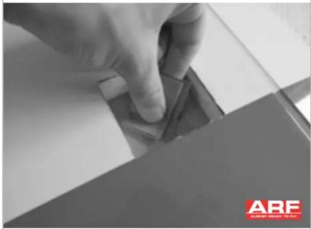
Use sandpaper to sand the bottom of the wing and the servo mount.
04
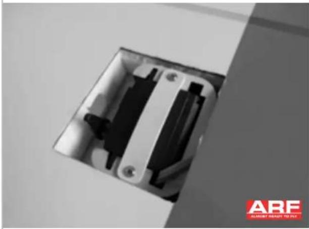
Route the servo cable in the wing and glue the the servo mount with the installed servo in the wing. We recommend Uhu Endfest 300. Please note that this glue takes several hours to cure.
06

Fix the aileron with tape to neutral and mark the position of the rudder horn.
07

Make a slot for tue rudder horn and glue it in with epoxy.
08

Install the linkage in the second hole of the servo horn. Enlarge the hole if needed. Connect the clevis to the rudder horn. Adjust the clevis so the aileron is centered when the servo is centered using the radio system. Tighten the nut against the clevis and use some threadlock.
09

Use hobby scissors to trim the aileron servo cover. Don't use the markings as these will not fit. You have to measure the correct dimension. The cover is attached to the wing using clear tape or thin CA.
ASSEMBLY THE FLAPS
10
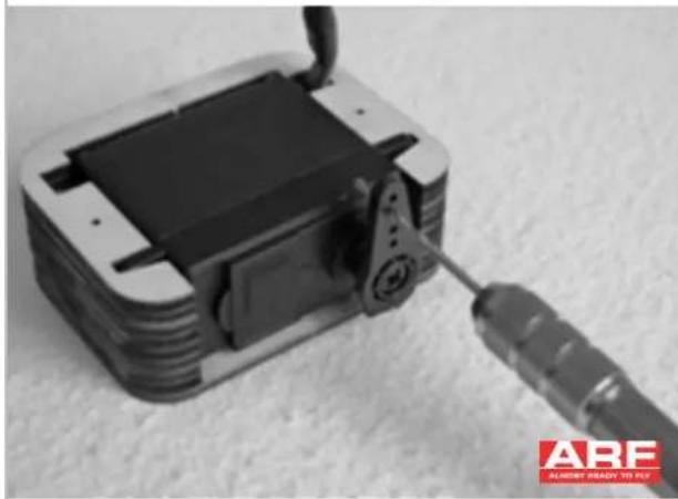
Remove any arm that may interfere with the operation of the servo. Enlarge the second hole to 1,6mm.
11

The flaps will be actuated through the top of the wing. Use a round file to prepare a channel for the linkage.
12

Enlarge the hole at the exit in the direction to the hinge, that the linkage will not be blocked when the flaps are full driven.
13
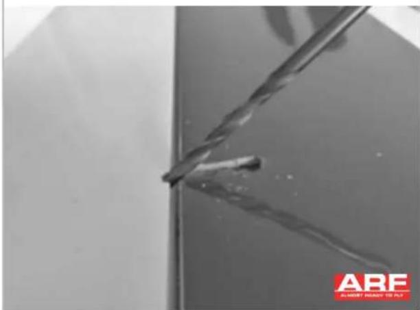
Drill a hole in a 45° angle for the rudder horn. You than the aileron.
14

Glue the ruderhorn with epoxy. The rudder-horn should stick nearly to the flat area in the flap.
15
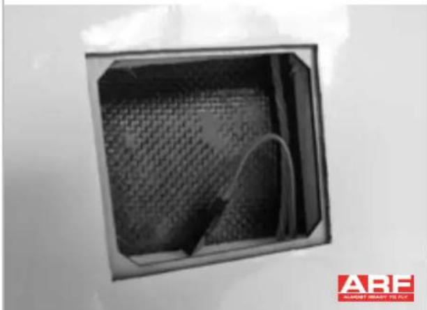
Sand the bottom of the wing and the servo mount thoroughly. Pull the cable of the aileron servo and a female servo connector through this part of the wing.
16

Fix the flap to the maximum up position (Speed position). Mount the clevis to the rudder horn.
17

Adjust the servo to the maximum throw with the servo horn facing to the leading edge of the wing. Fix the servo in the mount using the plastic strip and self tapping screws.
18

The cover is attached to the wing using clear tape.
19

Use hobby scissors to trim the cover and glue it.
20
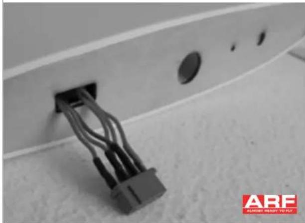
Solder a Multiplex connector to the servo cable.
ASSEMBLY THE FUSELAGE
21
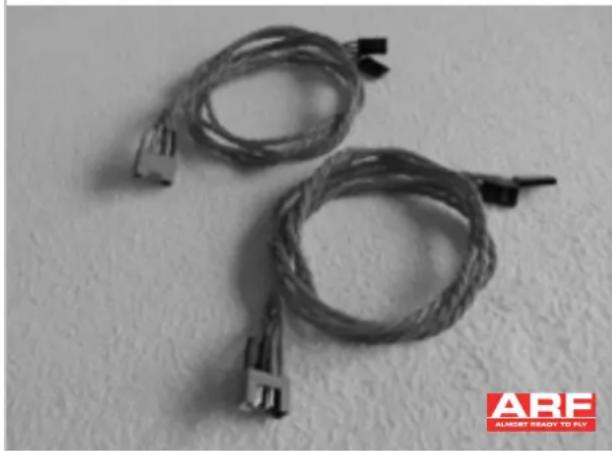
Prepare two cable harnesses with a lenght of 50-60cm.
22
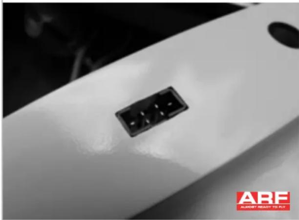
Route the cable harness through the fuselage and glue it flush with the wing cheeks of the fuselage. Please sand the connector before you start gluing.
23
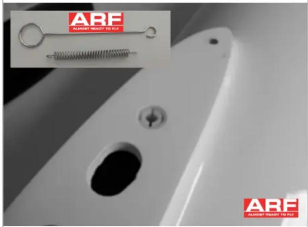
Glue the sleeve of the multilock (optional) flush with UHU Endfest 300 into the fuselage. Make sure to sand the outside of the sleeve beforehand. If you do not install multilock quick-release fasteners, the ARF model comes with a tensioning spring and mounting aid so that you can mount the surfaces evenly on the fuselage.
24

Install the elevator to the fuselage. Use the aluminium washers and make sure that the elevator is perpendicular to the rudder.
25
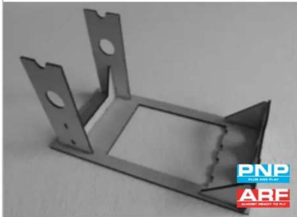
For assistance to glue the fuselage you will find plywood parts. Glue them as shown with thin CA.
26


Sand all parts thoroughly that will have contact with glue.
27

Apply enough Uhu Endfest to the adhesive surfaces and join the fuselage parts. Position the fuselage a shown on the device. The fuselage must have contact on the three points marked with arrows.
28

Adjust the elevator parallel to the wing joiner and let the epoxy cure.
ASSEMBLY THE RUDDER
29

Install four cyano hinges in the rudder.
30
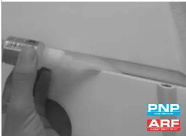
Attach the rudder to the fuselage and apply from both sides thin CA to the hinges. Let the CA cure for 30 minutes and don't use activator. Don't use medium or thick CA as this will not soak in the hinges.
31

Locate all parts for the rudder linkage.
32

Insert the servo. Use a 1,5mm drill for the servo holes and tighten the servo screws.
33

Route the cable end through the eye bolt and fasten it with the ferrule.
34
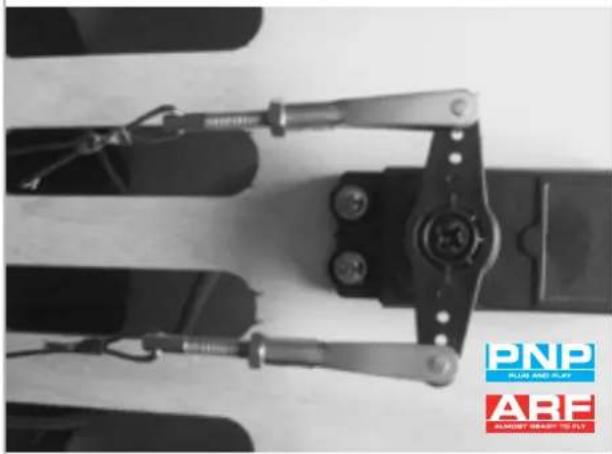
Route the eye bolt from the back of the fuse-lage and turn it on a clevis. Connect the clevis in the outermost hole of the servo.
35

Mark at the rudder the position of the rudder horn.
36

Drill a 3mm hole.
37

Glue the rudder horn as shown on the picture.
38

Pull a piece of 3mm Heatshrink tube on the cable.
39

Route the cable through the rudder horn and fix it with a ferrule. Pull the heatshrink tube on the ferrule and shrink it.
ASSEMBLY THE ELEVATOR
39
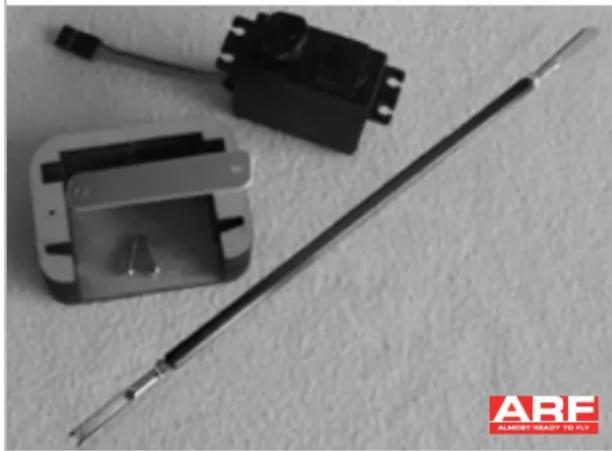
Locate all parts for installing the elevator servo.
40
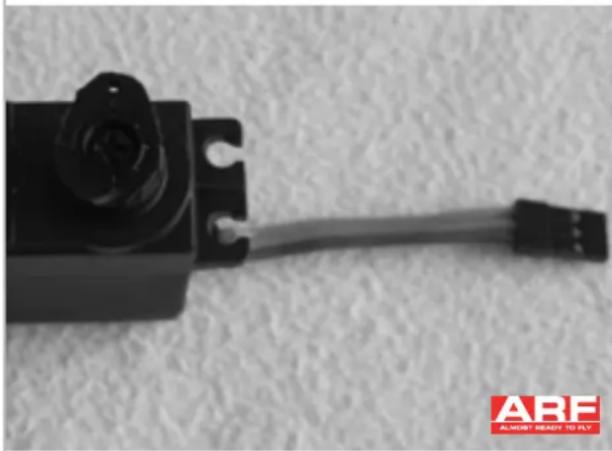
Prepare a servo horn with one hole.
41

Glue the servo horn in the center to the flat area in the rudder.
42

Mount the servo in the frame and make sure it sits tightly without any movement.
43

Attach the clevis to the servo horn.
44

Glue the cover with clear tape or UHU Por.
ASSEMBLY MPX-PLUGS AND MULTILOCK
45

Cover the area around the MPX connector with clear tape.
46
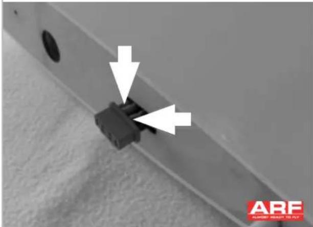
Please sand the connector before you start gluing. Apply Epoxy on the markings and assemble the wing on the fuselage while the epoxy cures. Please take care and align the connectors thoroughly.
47

Plug the pin of the multilock (optional, analog to Figure #23) into the socket. Apply epoxy resin to the pin and into the hole in the root rib of the surface. Then mount the surface and let it harden. Proceed in the same way with the outer surfaces.
ASSEMBLY THE MOTOR
48
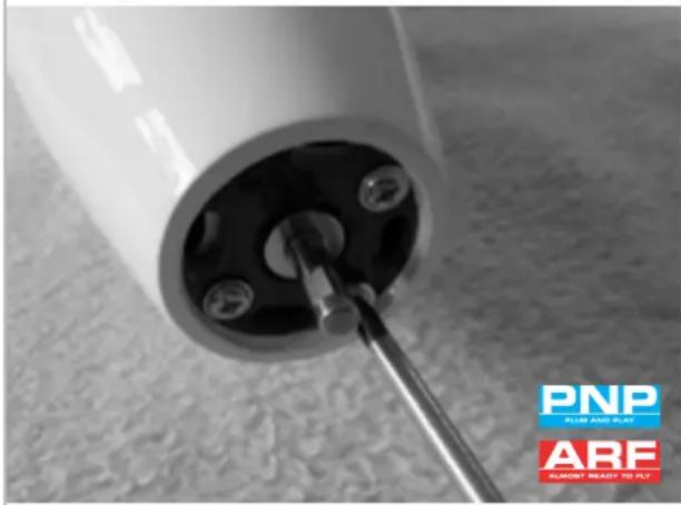
Install the motor and use threadlock.
FINAL ASSEMBLY
Your model is nearly finished. Finally, the outer wingtips must be glued to the inner part of the wing. Before gluing, make sure that the end strip is properly aligned between the wingtip and inner wing surface parts. This should result in a straight line. For bonding, it is best to use epoxy resin adhesive with a longer curing time to cleanly align the surface ends.

Do not fly the model without gluing the wingtips!
Additional to the Multilock it is mandatory to use tape as well to secure all wing parts together and the wings to the fuselage. The needed electronics are to be mounted and the transmitter programmed. Find the control throws and the CG below in the table. We are suggesting to use 3 flight modes (Standard, Speed, Thermal) as well as a Butterfly brake.
CONTROL THROWS
| Normal Thermal Speed Butterfly | ||||
| Ailerons ▲ 30 mm | ▼ 18 mm | ▲ 25 mm | ||
| Elevator ▲ 20 mm | ▼ 12 mm | ▼ 8 mm | ||
| Rudder ◀ 60 mm | ▶ 60 mm | |||
| Flaps | ▼ 5 mm | ▲ 3 mm | ▼ 55 mm | |
CENTER OF GRAVITY
110 bis 120 mm back from the leading edge of the wing and against the fuselage.
FLIGHT RECOMMENDATIONS
Choose a calm day for your first flight and take your time adjusting the model to your needs. Ask a buddy to throw the model horizontally in the air or use a glider dolly. Pull the elevator gently after gaining sufficient speed to climb. We wish you many nice and relaxing flights with your new Cyclone from Tomahawk.
SAFETY WARNINGS
As the user of this product, you are solely responsible for operating in a manner that does not endanger yourself and others or result in damage to the product or the property of others.
- Always keep a safe distance in all directions around your model to avoid collisions or injury. This model is controlled by a radio signal subject to interference from many sources outside your control. Interference can cause momentary loss of control.
- Always operate your model in open spaces away from full-size vehicles, traffic and people.
- Always carefully follow the directions and warnings for this and any optional support equipment (chargers, rechargeable battery packs, etc.).
• Always keep all chemicals, small parts and anything electrical out of the reach of children. - Always avoid water exposure to all equipment not specifically designed and protected for this
purpose. Moisture causes damage to electronics.
- Never place any portion of the model in your mouth as it could cause serious injury or even death.
- Never operate your model with low transmitter batteries.
• Always keep aircraft in sight and under control.
• Always use fully charged batteries. - Always keep transmitter powered on while aircraft is powered.
- Always remove batteries before disassembly.
• Always keep moving parts clean.
• Always keep parts dry.
• Always let parts cool after use before touching. - Always remove batteries after use.
- Always ensure failsafe is properly set before flying.
- Never operate aircraft with damaged wiring.
- Never touch moving parts.
NOTICE / NOTIZEN
NOTICE / NOTIZEN

TOMAHAWK
Sport


- INSTRUCTION MANUAL
- KONTAKT
- INSTRUCTIONS FOR DISPOSAL
- CONTACT
- DECLARATION OF CONFIRMITY
- INTRODUCTION
- ASSEMBLY THE FLAPS
- ASSEMBLY THE FUSELAGE
- ASSEMBLY THE RUDDER
- ASSEMBLY THE ELEVATOR
- ASSEMBLY MPX-PLUGS AND MULTILOCK
- FINAL ASSEMBLY
- CENTER OF GRAVITY
- FLIGHT RECOMMENDATIONS
- SAFETY WARNINGS
- TOMAHAWK
- SPORT
Brand : ROBBE
Model : Cyclone PNP
Category : Remote control toy