
BRIGGS & STRATTON 7000 WATT GENERATOR SYSTEM - Electric generator BRIGGS & STRATTON - Free user manual and instructions
Find the device manual for free BRIGGS & STRATTON 7000 WATT GENERATOR SYSTEM BRIGGS & STRATTON in PDF.

| Product Type | Emergency Electric Generator |
| Brand | Briggs & Stratton |
| Model | 7000 Watt Generator System |
| Rated Power | 7000 W (7 kW) |
| Output Voltage | 120/240 V AC, single-phase |
| Frequency | 60 Hz |
| Rated Current | 58.3 A at 120 V / 29.2 A at 240 V |
| Weight | 127 kg (280 lb) |
| Fuel | Natural gas or propane (LPG) |
| Natural gas supply pressure | 5 to 7 in. W.C. |
| LPG supply pressure | 11 to 14 in. W.C. |
| Starting type | Automatic (via transfer switch) or manual |
| Key features | Automatic backup power, weekly exercise cycle, fault detection, engine cooling |
| Safety | Low oil pressure protection, overspeed shutdown, circuit breaker, 15A fuse, spark arrester |
| Battery | 12 V DC, 33 Ah, sealed AGM |
| Engine oil type | Synthetic API SJ/CF 5W-30 |
| Maintenance | Regular oil change and oil filter replacement; exterior cleaning with damp cloth |
| Warranty | 2 years for residential use |
Frequently Asked Questions - BRIGGS & STRATTON 7000 WATT GENERATOR SYSTEM BRIGGS & STRATTON
User questions about BRIGGS & STRATTON 7000 WATT GENERATOR SYSTEM BRIGGS & STRATTON
0 question about this device. Answer the ones you know or ask your own.
Ask a new question about this device
Download the instructions for your Electric generator in PDF format for free! Find your manual BRIGGS & STRATTON 7000 WATT GENERATOR SYSTEM - BRIGGS & STRATTON and take your electronic device back in hand. On this page are published all the documents necessary for the use of your device. BRIGGS & STRATTON 7000 WATT GENERATOR SYSTEM by BRIGGS & STRATTON.
USER MANUAL BRIGGS & STRATTON 7000 WATT GENERATOR SYSTEM BRIGGS & STRATTON
7000 Rated Watts Home Generator System
Installation, Start-Up and Operator's Manual Manual de Instalación, Arranque y Operario Manuel d'Installation, Demarrage et Utilisation
Questions? Help is just a moment away!
Preguntas? Laapiaesjusta unmomento lejos!
IMPORTANT SAFETY INSTRUCTIONS 3-5
KNOW YOUR HOME STANDBY GENERATOR 6
KNOW YOUR CONTROL PANEL 7
SAVE THESE INSTRUCTIONS 8
INTRODUCTION 8
CUSTOMER RESPONSIBILITIES 8
INSTALLER RESPONSIBILITIES 8
INSTALLATION ASSISTANCE 8
For the Home Owner: 8
For the Installing Dealer/Contractor: 8
OWNER ORIENTATION 9
Fuel Factors 9
Power Decrease at High Altitude or High Temperature 9
INSTALLATION PROCEDURES 9
Unpacking Precautions 9
Delivery Inspection 9
Approved Transfer Switches 9
Shipment Contents 9
Lifting the Generator 10
Home Standby Generator Location 10
Generator Clearances 10
General Location Guidelines 10
Essential Circuits 11
Essential Circuit Selection 11-12
Disconnect Box Mounting Guidelines 12
Fuel Inlet Dimensions 12
Removable Roof and Access Door 12
To remove roof: 12
To remove access door: 12
To install access door and roof: 12
THE GASEOUS FUEL SYSTEM 13-14
Fuel Consumption 14
Fuel Pipe Sizing 15
Fuel Comparison Chart 16
Size of Propane Tank Required at Various Temperatures When Kept at Least Half Full 16
WIRE CONNECTIONS 17
Recommended Torque Values. 17
Generator AC Connection System 17
Grounding the Generator 17
Generator Control Circuit Connection 17
Remote Diagnostic LED Plate 17
BEFORE INITIAL START-UP 17
Engine Oil 17
Oil Considerations 17
Battery Connection 18
Fuel Supply System 18
FUEL SYSTEM SELECTION 19
INITIAL START-UP (NO LOAD) 19
Utility Voltage Dropout Sensor 19
Utility Voltage Pickup Sensor. 19
Engine Cool-down Timer 19
SETTING EXERCISE TIMER 20
INSTALLATION INSPECTION 20
SPECIFICATIONS 21
Checking Automatic Operation 21
Servicing The System 21
FAULT DETECTION SYSTEM 21
Reset Fault Detection System 22
No LED - Discharged Battery 22
Low Oil Pressure 22
Engine Fails to Start. 22
Low Frequency. 22
Engine Overspeed 22
GENERATOR MAINTENANCE 23
Changing Engine Oil and Filter 23
Changing Oil 23
Changing Oil Filter 23
To Clean the Generator 24
When Calling the Factory 24
STORAGE 24
TROUBLESHOOTING 25
SCHEMATIC 26
WIRING DIAGRAM 27
REPLACEMENT PARTS 28-34
WARRANTY 35
ESPANOL 36-61
FRANÇAIS 62-88
SAVE THESE INSTRUCTIONS
IMPORTANT SAFETY INSTRUCTIONS
The safety alert symbol (▲) is used with a signal word (DANGER, CAUTION, WARNING), a pictorial and/or a safety message to alert you to hazards. DANGER indicates a hazard which, if not avoided, will result in death or serious injury. WARNING indicates a hazard which, if not avoided, could result in death or serious injury. CAUTION indicates a hazard which, if not avoided, might result in minor or moderate injury. NOTICE, indicates a situation that could result in equipment damage. Follow safety messages to avoid or reduce the risk of injury or death.
The manufacturer cannot possibly anticipate every possible circumstance that might involve a hazard. The warnings in this manual, and the tags and decals affixed to the unit are, therefore, not all-inclusive. If you use a procedure, work method or operating technique that the manufacturer does not specifically recommend, you must satisfy yourself that it is safe for you and others. You must also make sure that the procedure, work method or operating technique that you choose does not render the generator unsafe.
NOTE: Your generator is equipped with a spark arrester muffler. The spark arrester must be maintained in effective working order by the owner/operator. In the State of California, a spark arrester is required by law (Section 4442 of the California Public Resources Code). Other states may have similar laws. Federal laws apply on federal lands.
Hazard Symbols and Meanings

Toxic Fumes

Rotating Parts

Electrical Shock

Hot Surface

Explosion

Fire

Explosive Pressure

Chemical Burn

Operator's Manual

WARNING
The engine exhaust from this product contains chemicals known to the State of California to cause cancer, birth defects, or other reproductive harm.

WARNING

Storage batteries give off explosive hydrogen gas during recharging.

Slightest spark will ignite hydrogen and cause explosion.
Battery electrolyte fluid contains acid and is extremely caustic.
Contact with battery contents will cause severe chemical burns.
A battery presents a risk of electrical shock and high short circuit current.
- DO NOT dispose of battery in a fire.
- DO NOT allow any open flame, spark, heat, or lit cigarette during and for several minutes after charging a battery.
- DO NOT open or mutilate the battery.
- Wear protective goggles, rubber apron, and rubber gloves.
- Remove watches, rings, or other metal objects.
- Use tools with insulated handles.

WARNING

Running engine gives off carbon monoxide, an odorless, colorless, poison gas.
Breathing carbon monoxide can cause headache, fatigue, dizziness, vomiting, confusion, seizures, nausea, fainting or death.
- Operate generator ONLY outdoors.
Install a battery operated carbon monoxide alarm near the bedrooms. - Keep exhaust gas from entering a confined area through windows, doors, ventilation intakes, or other openings.
| WARNING | |
| ? | Generator produces hazardous voltage. Failure to properly ground generator can result in electrocution. Failure to isolate generator from power utility can result in death or injury to electric utility workers due to backfeed of electrical energy. |
| ·When using generator for backup power, notify utility company. ·DO NOT touch bare wires or receptacles. ·DO NOT use generator with electrical cords which are worn, frayed, bare or otherwise damaged. ·DO NOT handle generator or electrical cords while standing in water, while barefoot, or while hands or feet are wet. ·If you must work around a unit while it is operating, stand on an insulated dry surface to reduce shock hazard. ·DO NOT allow unqualified persons or children to operate or service generator. ·In case of an accident caused by electrical shock, immediately shut down the source of electrical power and contact the local authorities. Avoid direct contact with the victim. ·Despite the safe design of the Home Generator System, operating this equipment imprudently, neglecting its maintenance or being careless can cause possible injury or death. ·Remain alert at all times while working on this equipment. NEVER work on the equipment when you are physically or mentally fatigued. ·Before performing any maintenance on the generator, disconnect the battery cable indicated by a NEGATIVE, NEG or (-) first. When finished, reconnect that cable last. ·After your Home Generator System is installed, the generator may crank and start without warning any time there is a power failure. To prevent possible injury, always set the AUTO/OFF/MANUAL switch to OFF, remove the service disconnect from the disconnect box AND remove the 15 Amp fuse BEFORE working on the equipment. | |
| WARNING | |
| Propane and Natural Gas are extremely flammable and explosive. Fire or explosion can cause severe burns or death. | |
| ·Install the fuel supply system according to applicable fuel-gas codes. ·Before placing the Home Generator System into service, the fuel system lines must be properly purged and leak tested. ·After the generator is installed, you should inspect the fuel system periodically. ·NO leakage is permitted. ·DO NOT operate engine if smell of fuel is present or other explosive conditions exist. ·DO NOT smoke around the generator. Wipe up any oil spills immediately. Ensure that no combustible materials are left in the generator compartment. Keep the area near the generator clean and free of debris. | |
| WARNING | |
| Contact with muffler area can result in serious burns.Exhaust heat/gases can ignite combustibles or structures causing a fire. | |
| DO NOT touch hot parts and AVOID hot exhaust gases.Allow equipment to cool before touching.DO NOT install the generator closer than 5 feet (1.5m) from any combustibles or structures with combustible walls having a fire resistance rating of less than 1 hour.Keep at least 3 ft.(91 cm)clearance on all sides of generator including overhead.Code of Federal Regulation (CFR) Title 36 Parks, Forests, and Public Property require equipment powered by an internal combustion engine to have a spark arrester,maintained in effective working order, complying to USDA Forest service standard 5100-1C or later revision.In the State of California a spark arrester is required under section 4442 of the California Public resources code. Other states may have similar laws. | |
| Starter and other rotating parts can entangle hands, hair, clothing, or accessories. | |
| ·NEVER operate generator without protective housing or covers. ·DO NOT wear loose clothing, jewelry or anything that may be caught in the starter or other rotating parts. ·Tie up long hair and remove jewelry. | |
| CAUTION | |
| Installing the 15A fuse could cause the engine to start. | |
| ·Observe that the 15 Amp fuse has been removed from the control panel for shipping. ·DO NOT install this fuse until all plumbing and wiring has been completed and inspected. | |
| CAUTION | |
| Excessively high operating speeds increase risk of injury and damage to generator. Excessively low speeds impose a heavy load. | |
| ·DO NOT tamper with governed speed. Generator supplies correct rated frequency and voltage when running at governed speed. ·DO NOT modify generator in any way. | |
| NOTICE | |
| Exceeding generators wattage/amperage capacity can damage generator and/or electrical devices connected to it. | |
| ·See “Essential Circuits”. ·Start generator and let engine stabilize before connecting electrical loads. | |
| NOTICE |
| Improper treatment of generator can damage it and shorten its life. |
| Use generator only for intended uses. If you have questions about intended use, ask dealer or contact Briggs and Stratton. Operate generator only on level surfaces. Adequate, unobstructed flow of cooling and ventilating air is critical to correct generator operation. The doors must be installed whenever the unit is running. DO NOT expose generator to excessive moisture, dust, dirt, or corrosive vapors. Despite the safe design of the Home Generator System, operating this equipment imprudently, neglecting its maintenance or being careless can cause possible injury or death. Remain alert at all times while working on this equipment. NEVER work on the equipment when you are physically or mentally fatigued. DO NOT start engine with air cleaner or air cleaner cover removed. DO NOT insert any objects through cooling slots. DO NOT use the generator or any of its parts as a step. Stepping on the unit can cause stress and break parts. This may result in dangerous operating conditions from leaking exhaust gases, fuel leakage, oil leakage, etc.. If connected devices overheat, turn them off and disconnect them from generator. Shut off generator if: -electrical output is lost; -equipment sparks, smokes, or emits flames; -unit vibrates excessively. |
KNOW YOUR HOME STANDBY GENERATOR

Read this Operator's Manual and safety rules before operating your generator.
Compare the illustrations with your generator, to familiarize yourself with the locations of various controls and adjustments. Save this manual for future reference.
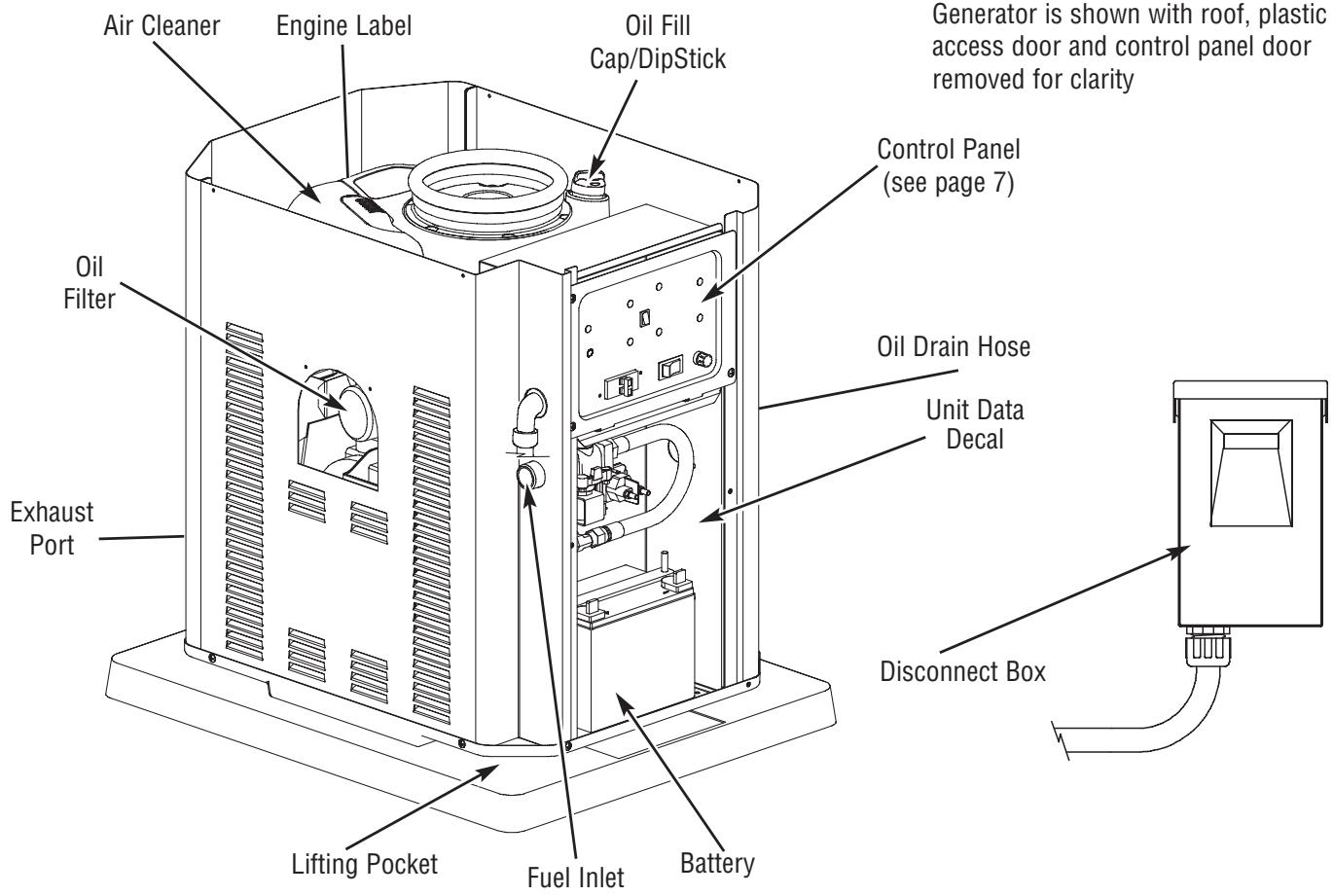
Air Cleaner - Uses a dry type filter element and foam precleaner to protect engine by filtering dust and debris out of intake air..
Battery — 12 Volt DC, 33 Amp-Hour sealed battery provides power to start the engine. Battery receives trickle charge whenever generator is not running.
Control Panel - Used for various test, operation and maintenance functions. See "KNOW YOUR CONTROL PANEL" on the next page.
Disconnect Box — Convenient junction box for ease of installation. Allows you to connect to generator output and disconnect utility input.
Engine Label (stamped on top of valve cover) — Identifies engine model and type.
Exhaust Port — High-performance muffler lowers engine noise to comply with most residential codes.
Fuel Inlet — Attach appropriate fuel supply to generator here.
Lifting Pocket - Provided at each corner for lifting generator.
Oil Fill Cap/Dipstick — Check and fill engine with recommended oil here.
Oil Drain Hose - Provided to facilitate oil changing.
Oil Filter — Filters engine oil to prolong generator life.
Unit Data Decal - Identifies unit by serial number.
KNOW YOUR CONTROL PANEL
Compare this Control Panel illustration with your generator to familiarize yourself with the location of these important controls:
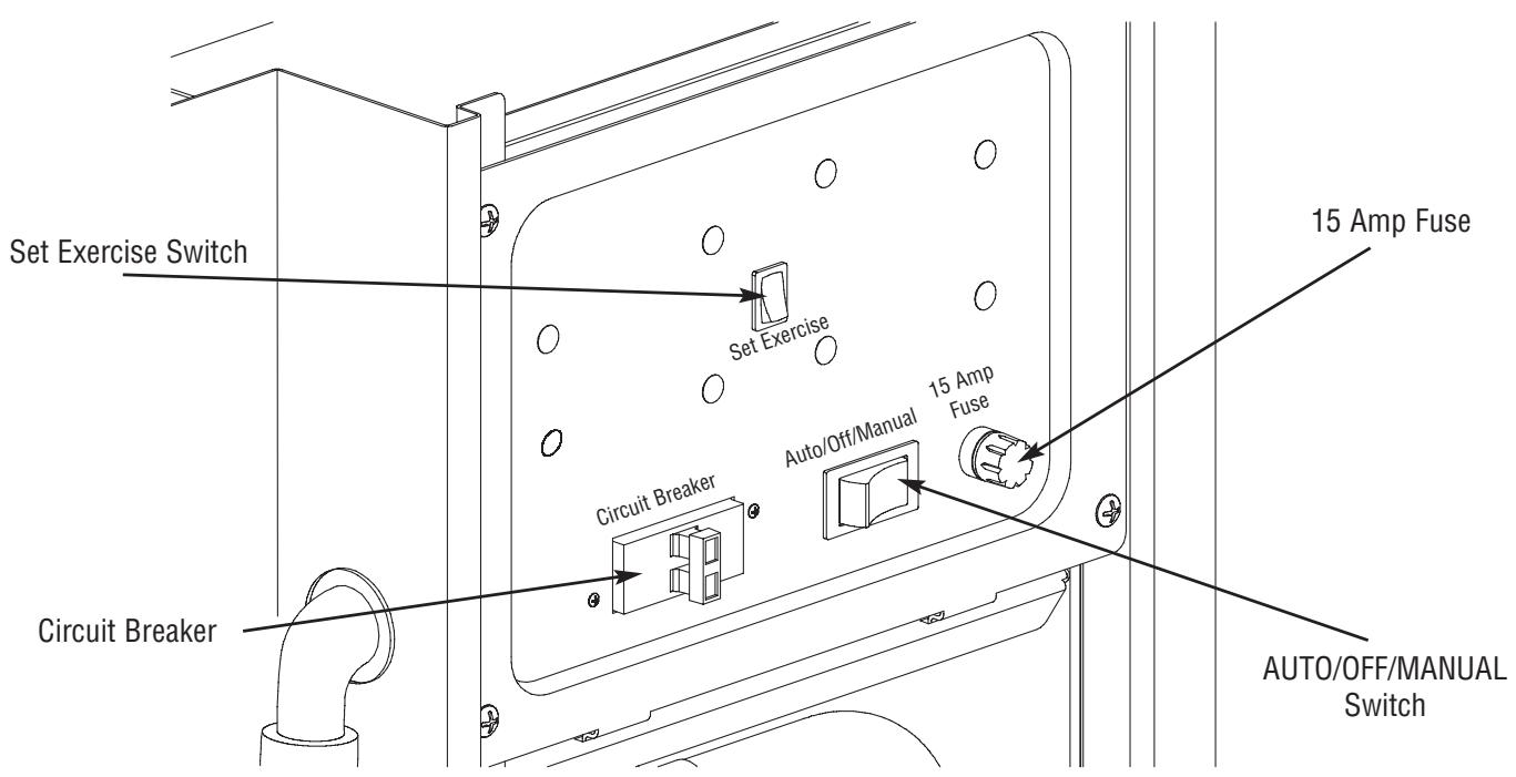
15 Amp Fuse — Protects the Home Standby Generator DC control circuits. If the fuse has melted open or was removed, the engine cannot crank or start. Replace the fuse using only an identical BUSS AGC 15A fuse.
AUTO/OFF/MANUAL Switch — This three-position switch is used as follows:
-
"AUTO" position is the normal operating mode. If a utility power outage is sensed, the generator will start automatically. When utility power is restored, the generator will shut down, and is ready for the next utility power outage.
-
“OFF” position turns off generator, prevents generator from starting and resets any faults.
- “MANUAL” position starts the generator. It is used for maintenance or diagnostic functions.
Circuit Breaker — Protects the system from over-current conditions and must be in the "On" position to supply power to the Transfer Switch.
Set Exercise Switch - Used to set the exercise cycle start time and day-of-the-week. Exercise cycle only occurs in AUTO mode.
SAVE THESE INSTRUCTIONS
This manual contains important instructions that should be followed during installation and maintenance of the generator and battery.
INTRODUCTION
Thank you for your purchase of a Briggs & Stratton Home Standby Generator. This product is intended for use as an optional standby system which provides an alternate source of electric power and to serve loads such as heating, refrigeration systems, and communication systems that, when stopped during any power outage, could cause discomfort, or the like. This product DOES NOT qualify for emergency standby as defined by NFPA 70 (NEC).
This manual is an important document and should be retained by the owner after installation has been completed.
This manual contains installation, startup and adjustment instructions for a Home Standby Generator that supplies 120/240 Volt, single phase, 60Hz devices. The Home Standby Generator may be operated on LP vapor or natural gas fuel.
Every effort has been made to ensure that the information in this manual is both accurate and current. However, the manufacturer reserves the right to change, alter or otherwise improve the generator at any time without prior notice.
Briggs and Stratton has made every effort to provide for a safe, streamlined and cost-effective installation. Because each installation is unique, it is impossible to know of and advise the trade of all conceivable procedures and methods by which installation might be achieved. Neither could we know of possible hazards and/or the results of each method or procedure. For these reasons,
Only current licensed electrical and plumbing contractors should attempt Home Standby Generator installations. Installations must strictly comply with all applicable codes, industry standards and regulations.
CUSTOMER RESPONSIBILITIES
- Read and follow the instructions given in this manual, especially the section regarding selecting essential circuits.
- Follow a regular schedule in maintaining, caring for and using your Home Standby Generator, as specified in this manual.
INSTALLER RESPONSIBILITIES
- Read and observe the safety rules.
- Read and follow the instructions given in this manual. IMPORTANT: If operating the generator below 40^ , it is recommended that a battery warmer be installed. If operating the generator below 32^ , a battery warmer MUST be installed. This item is available at your local servicing dealer.
INSTALLATION ASSISTANCE
For the Home Owner:
To help you make informed choices and communicate effectively with your installation contractor(s),
Read and understand the Owner Orientation Section of this manual BEFORE contracting or starting your Home Standby Generator installation.
To arrange for proper installation, contact the store at which you purchased your Briggs & Stratton Standby Generator, your dealer, a licensed electrician or your utility power provider.
The Home Standby Generator Warranty is VOID unless the generator is installed by licensed electrical and plumbing professionals.
For the Installing Dealer/Contractor:
- For most applications, this manual contains all the information required to properly install and start the Home Standby Generator. This manual also describes essential circuit selection, routine operation and owner maintenance procedures.
- If you need more information, call 1-800-743-4115, between 8:00 AM and 5:00 PM CT.
The Emission Control System for this generator is warranted for standards set by the U.S. Environmental Protection Agency and by the California Air Resources Board (CARB).
OWNER ORIENTATION
This section provides the Home Standby Generator owner with the information necessary to achieve the most satisfactory and cost effective installation possible.
The illustrations are for typical circumstances and are meant to familiarize you with the installation options available with the Home Standby Generator. A thorough understanding of these options will provide fundamental control over the cost of installation, as well as ensure final satisfaction and security.
Federal and local codes, appearance, noise levels, fuel types, and distances are the factors that must be considered when negotiating with an installation professional. As the distance from the existing electrical service and gaseous fuel supply increases, so must the piping and wiring materials. This is necessary to comply with local codes, overcome electrical voltage drops and gaseous fuel pressure drops.
The factors mentioned above will have a direct effect on the overall price of your Home Standby Generator installation.
NOTE: In some areas you may need to acquire electrical permits for installing the Home Standby Generator, building permits for installing gas lines, and permits for noise allowances. Your installer should check your local codes AND obtain the permits before installing the generator.
Fuel Factors
An important consideration affecting the entire installation is the type of fuel used by your Home Standby Generator. The generator was factory tested and adjusted using natural gas as a fuel. liquid propane vapor (LP) may also be used as fuel by installing the included conversion kit.
For proper generator performance, the following fuel guidelines are recommended:
In engines set up to run on liquid propane vapor (LP), commercial grade HD5 propane with a minimum fuel energy of 2500 BTUs/ft³ with maximum propylene content of 5% and butane and heavier gas content of 2.5% and minimum propane content of 90% .

WARNING


Propane and Natural Gas are extremely flammable and explosive.
Fire or explosion can cause severe burns or death.
- The Home Generator System is equipped with an automatic safety gas "fuel shut-off" valve.
- DO NOT operate the equipment if the "fuel shut-off" valve is missing or inoperative.
Power Decrease at High Altitude or High Temperature
Air density is less at high altitudes, resulting in less available engine power. Specifically, engine power will decrease 3.5% for each 1,000 feet (300 meters) above sea level and 1% for each 10^ ( 5.6^ ) above 77^ ( 25^ ). Make sure you and your installer consider these factors when determining total generator load.
INSTALLATION PROCEDURES
Unpacking Precautions
The unit is shipped bolted to its mounting pad, ready for installation. Avoid damage from dropping, bumping, collision, etc. Store and unpack carton with the proper side up, as noted on the shipping carton.
Delivery Inspection
After removing the carton, carefully inspect the Home Standby Generator for any damage that may have occurred during shipment.
IMPORTANT: If loss or damage is noted at time of delivery, have the person(s) making delivery note all damage on the freight bill and affix his signature under the consignor's memo of loss or damage. If loss or damage is noted after delivery, separate the damaged materials and contact the carrier for claim procedures. Missing or damaged parts are not warranted.
Approved Transfer Switches
The Home Standby Generator should be used ONLY with Briggs & Stratton Power Products UL approved Transfer Switches. Connection to any other transfer switch will void your generator warranty.
Shipment Contents
The Home Standby Generator is supplied with:
Home Standby Generator w/disconnect box
- Pre-attached mounting pad
- One flexible hook-up hose (meets UL 569 and CSA 8.3)
- Installation, start-up and operator's manual
- Installation checklist
Remote diagnostic LED plate
- Oil drain tray
- Touch-up paint
- One spare 15A fuse
- LP conversion kit
- Roof hardware bag
Lifting the Generator
The generator weighs more than 280 pounds. Proper tools, equipment and qualified personnel should be used in all phases of handling and moving generator.

WARNING

Lifting Hazard / Heavy Object Can cause muscle strain or back injury.
- DO NOT lift or move generator without assistance.
- DO NOT lift unit by roof as damage to generator will occur.
Lifting pockets are provided at each corner between the base of the generator and its mounting pad. Retouch any chipped paint with supplied touch-up paint.
Home Standby Generator Location
Before installing generator, consult with homeowner and convey the following guidelines which may affect the desired location.

WARNING

Exhaust heat/gases can ignite combustibles or structures causing a fire.
- DO NOT install the generator closer than 5 feet (1.5m) from any combustibles or structures with combustible walls having a fire resistance rating of less than 1 hour.
- Keep at least 3 ft. (91 cm) clearance on all sides of generator including overhead.
Generator Clearances
Install generator outdoors in an area which will not accumulate deadly exhaust gas. DO NOT install generator where exhaust gas could accumulate and enter inside or be drawn into a potentially occupied building. Ensure exhaust gas is kept away from any windows, doors, ventilation intakes or other openings that can allow exhaust gas to collect in a confined area (Figure 1). Prevailing winds and air currents should be taken into consideration when positioning generator.
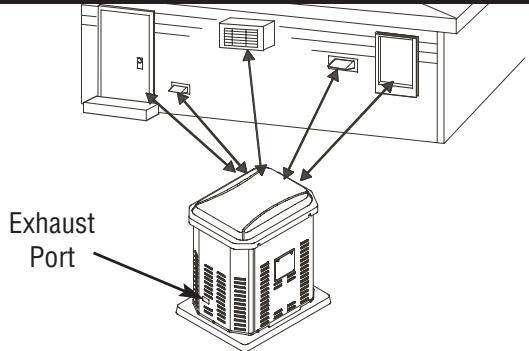
Figure 1 — Home Standby Generator Clearances
| WARNING | |
| Running engine gives off carbon monoxide, an odorless, colorless, poison gas. Breathing carbon monoxide can cause headache, fatigue, dizziness, vomiting, confusion, seizures, nausea, fainting or death. | |
| ·Operate generator ONLY outdoors. ·Install a battery operated carbon monoxide alarm near the bedrooms. ·Keep exhaust gas from entering a confined area through windows, doors, ventilation intakes, or other openings. | |
General Location Guidelines
Install the unit outdoors ONLY.
- Place the unit in a prepared location that is flat and has provisions for water drainage.
- Install the unit in a location where sump pump discharge, rain gutter down spouts, roof run-off, landscape irrigation, or water sprinklers will not flood the unit or spray the enclosure and enter any air inlet our outlet openings.
- Install the unit where the location of any services such as phone, electrical, fuel, air conditioning, irrigation, including covered, concealed and underground services will not be affected or obstructed.
- Install the unit where air inlet and outlet openings will not become obstructed by leaves, grass, snow, etc. If prevailing winds will cause blowing or drifting, you may need to construct a windbreak to protect the unit.
- Install the generator as close as possible to the fuel supply to reduce length of pipes.
IMPORTANT: Laws or local codes may regulate the distance to the fuel supply.
The Home Standby Generator is shipped already attached to its mounting pad. Unless mandated by local code, a concrete slab is not required.
If mandated by local code, construct a concrete slab at least 3 inches thick and 6 inches longer and wider than the unit. Attach unit to slab with 1/4 ” diameter (minimum) masonry anchor bolts long enough to retain the unit.
Essential Circuits
Consult with owner to clearly identify the circuits in building that are "essential".
It is important that you understand which circuits the owner wants to include as "Essential Circuits". Depending on the power consumed by these circuits, most or all of them can be switched to the Home Standby Generator for the duration of normal power interruption.
The wattage reference guide shown in Figure 2 will assist the owner with their decision-making process. It provides the wattage used by many ordinary household devices. Use it as a guide when selecting essential circuits. Review this information with the owner and convey any technical considerations that might affect the cost of installation.
Essential Circuit Selection
When selecting the essential circuits that will be switched to "Standby Power," it is important that the sum of the combined circuit loads does not exceed the wattage/amperage capacity of the generator. To help you with your selection of essential circuits, please consider the following:
- Add up the total wattage of all electrical devices to be connected at one time. This total should NOT be greater than the generator's wattage capacity.
- The rated wattage of lights can be taken from light bulbs. The rated wattage of tools, appliances and motors can usually be found on a data plate or decal affixed to the device.
- If the appliance, tool or motor nameplate does not list wattage, multiply volts times the ampere rating to determine watts (Volts × Amps = Watts).
- Some electric motors (induction types) require about three times more watts of power for starting than for running. This surge lasts for only a few seconds. Be sure you allow for this high starting wattage when selecting electrical devices that will be energized by the Home Standby Generator:
Figure the watts required to start the largest motor.
- Add that to the total running watts of all other connected loads.
This Briggs & Stratton Home Standby Generator complies with the following "stationary standby power rating":
The standby power rating is applicable for supplying power for the duration of normal power interruption. NO sustained overload capability is available for this rating.
Figure 2 — Wattage Reference Guide
| Device | Running Watts | |
| □ Air Conditioner (12,000 Btu)* | 1700 | |
| □ Air Conditioner (24,000 Btu)* | 3800 | |
| □ Air Conditioner (40,000 Btu)* | 6000 | |
| □ Battery Charger (20 Amp) | 500 | |
| □ Circular Saw (6-1/2") | 800 to 1000 | |
| □ Clothes Dryer (Electric)* | 5750 | |
| □ Clothes Dryer (Gas)* | 700 | |
| □ Clothes Washer* | 1150 | |
| □ Coffee Maker | 1750 | |
| □ Compressor (1 HP)* | 2000 | |
| □ Compressor (1/2 HP)* | 1400 | |
| □ Compressor (3/4 HP)* | 1800 | |
| □ Curling Iron | 700 | |
| □ Dehumidifier* | 650 | |
| □ Electric Blanket | 400 | |
| □ Electric Range (per element) | 1500 | |
| □ Electric Skillet | 1250 | |
| □ Freezer* | 700 | |
| □ Furnace Fan (3/5 HP)* | 875 | |
| □ Garage Door Opener* | 500 to 750 | |
| □ Hair Dryer | 1200 | |
| □ Hand Drill | 250 to 1100 | |
| □ Iron | 1200 | |
| □ Jet Pump* | 800 | |
| □ Light Bulb | 100 | |
| □ Microwave Oven | 700 to 1000 | |
| □ Milk Cooler* | 1100 | |
| □ Oil Burner on Furnace | 300 | |
| □ Oil Fired Space Heater (140,000 Btu) | 400 | |
| □ Oil Fired Space Heater (30,000 Btu) | 150 | |
| □ Oil Fired Space Heater (85,000 Btu) | 225 | |
| □ Radio | 50 to 200 | |
| □ Refrigerator | 700 | |
| □ Slow Cooker | 200 | |
| □ Submersible Pump (1 HP)* | 2000 | |
| □ Submersible Pump (1/2 HP)* | 1500 | |
| □ Submersible Pump (1-1/2 HP)* | 2800 | |
| □ Sump Pump* | 800 to 1050 | |
| □ Table Saw (10")* | 1750 to 2000 | |
| □ Television | 200 to 500 | |
| □ Toaster | 1000 to 1650 | |
| *Allow three (3) times listed watts for starting device | ||
This rating is applicable to installations served by a reliable normal utility source. This rating is only applicable to variable loads with an average load factor of 80% of the standby rating. The standby rating is only applicable for optional standby power where the generator set serves as the backup to the normal utility source.
Use the "Wattage Reference Guide" provided and mark those circuits you consider "critical" or "essential". Make sure you and your installer consider the generator's altitude above sea level and the ambient temperature range when determining total generator load.
Disconnect Box Mounting Guidelines
The disconnect box is a NEMA Type 3R enclosure suitable for outdoor use. Installations must strictly comply with all applicable codes, industry standards and regulations.
Guidelines for mounting the disconnect box include:
- The disconnect box must be installed with appropriate hardware for conduit connections.
- Install disconnect box on a firm, sturdy supporting structure, making sure it is level and plumb.
- NEVER install disconnect box where any corrosive substance might drip onto enclosure.
- Protect disconnect box at all times against excessive moisture, dust, dirt, lint, construction grit and corrosive vapors.
The typical installation of the disconnect box is depicted in Figure 3. Discuss layout suggestions/changes with owner before beginning installation process.
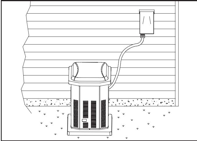
Figure 3 — Typical Disconnect Box Mounting
Fuel Inlet Dimensions
Figure 4, below, depicts the location of the fuel piping connector.
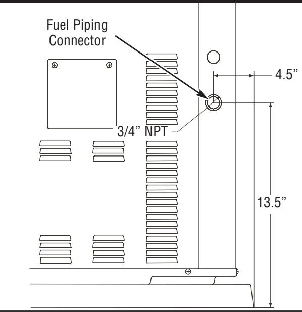
Figure 4 — Generator Fuel Attachment Location
Removable Roof and Access Door
The Home Standby Generator is equipped with an enclosure that has a removable roof and an access door for the control panel.
To Remove Roof:
Remove the four screws and lift off.
To Remove Access Door:
- Remove roof as described above.
- Remove screw at top of access door.
- Pull access door outward (away) from unit while pulling door upward and out of base. Door will come free of generator enclosure.
To Install Access Door and Roof:
- Guide bottom of access door into base.
- Push access door until it is flush with sides.
- Replace door screw.
- Replace roof and screws.
THE GASEOUS FUEL SYSTEM

WARNING

Propane and Natural Gas are extremely flammable and explosive.

Fire or explosion can cause severe burns or death.
- LP gas is heavier than air and will settle in low areas.
- Natural gas is lighter than air and will collect in high areas.
- The slightest spark can ignite these fuels and cause an explosion.
- DO NOT light a cigarette or smoke.
The information provided below is to assist gaseous fuel system technicians in planning installations. In no way should this information be interpreted to conflict with applicable fuel gas codes. Consult with your local fuel supplier or Fire Marshall if questions or problems arise.
TO THE INSTALLER: Consult with the Home Generator System owner(s) and convey any technical considerations that might affect their installation plans before applying these general guidelines.
The following general rules apply to gaseous fuel system piping:
- The piping should be of a material that conforms to federal and local codes, rigidly mounted and protected against vibration.
- Piping should be protected from physical damage where it passes through flower beds, shrub beds, and other cultivated areas where damage could occur.
- Install the flexible, gaseous hose that meets UL 569 and CSA 8.3 (supplied) between the Home Generator System Fuel Inlet port and rigid piping to prevent thermal expansion or contraction from causing excessive stress on the piping material.

CAUTION
The supplied flexible gaseous pipe is not to be installed underground or in contact with the ground.
- The entire flexible gaseous pipe must be visible for periodic inspection and must not be concealed within, contact, or run through any wall, floor, or partition.
NOTE: Where local conditions include earthquake, tornado, unstable ground, or flood hazards, special consideration shall be given to increase strength and flexibility of piping supports and connections.
- Piping must be of the correct size to maintain the required supply pressures and volume flow under varying generator load conditions with all gas appliances connected to the fuel system turned on and operating.
- Use an approved pipe sealant or joint compound on all threaded fittings to reduce the possibility of leakage.
- Installed piping must be properly purged and leak tested, in accordance with applicable codes and standards.

WARNING

Propane and Natural Gas are extremely flammable and explosive.

Fire or explosion can cause severe burns or death.
- Before placing the Home Generator System into service, the fuel system lines must be properly purged and leak tested.
- NO leakage is permitted.
Consider the following factors when planning to install the fuel supply system:
The Home Generator System engine is fitted with a fuel mixer system that meets the specifications of the California Air Resources Board for "tamper-proof" dual fuel systems. The unit will run on natural gas or liquefied propane vapor.
- A minimum of one accessible, approved manual shutoff valve shall be installed in the fuel supply line within 6 ft (1.8 m) of the Home Generator System. A union or flanged connection shall be provided downstream from this valve to permit removal of controls.
- Natural gas fuel supply pressure at the generator's fuel inlet port should be between 5 to 7 inches of water (in. W.C.) at full load. LP fuel supply pressure should be 11 to 14 inches of water (in. W.C.) at full load.
The Home Generator System unit has been factory set to run on natural gas. If you need to change from natural gas to LP gas, the unit will need to be reconfigured, as described on page 19.
It is recommended that the fuel connection incorporate the following components:
- A manual fuel shut-off valve located in the interior of the building.
- A manual fuel shut-off valve located outside the building, just before the generator unit.
- Where the formation of hydrates or ice is known to occur, piping should be protected against freezing. The termination of hard piping should include a sediment trap where condensate is not likely to freeze.
- A manometer port should be provided.
The manometer port permits temporary installation of a manometer (Figure 5), to ensure that the engine receives the correct fuel pressure to operate efficiently throughout its operating range.
Figure 5 — Temporary Manometer Installed
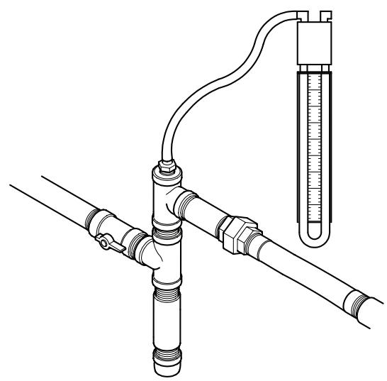
NOTE: A digital manometer, P/N 19495, is available at your local Briggs & Stratton service center.
When the initial test runs are completed, the manometer is removed and the port is plugged. A typical final fuel connection assembly is shown in Figure 6.
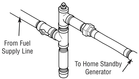
Figure 6 — Completed Fuel Connections
Fuel Consumption
See Figure 7 for estimated fuel supply requirements at half and full load for both natural gas and LP vapor.
Figure 7 — Fuel Supply Requirements
| Natural Gas* | LP Vapor** | ||
| 1/2 Load | Full Load | 1/2 Load | Full Load |
| 80 | 137 | 33 | 56 |
| * = Natural Gas is in cubic feet per hour ** = LP Vapor is in cubic feet per hour | |||
Fuel Pipe Sizing
Figures 8 and 9 provide the maximum capacity of pipe in cubic feet of gas per hour for gas pressures of 0.5 psi or less and a pressure drop of 0.3 in. water column. Specific gravity of gas is shown.
Listed values compensate for a nominal amount of restriction from bends, fittings, etc. If an unusual number of fittings, bends, or other restrictions are used, please refer to federal and local codes.
| Figure 8 — NATURAL GAS (NG) Pipe Size - Gas Flow Chart, in cubic feet per hour | |||||||||||
| NPT | 10ft | 15ft | 20ft | 30ft | 40ft | 50ft | 60ft | 70ft | 80ft | 90ft | 100ft |
| 1/2" | 168 | 146 | 115 | 93 | 79 | 70 | 63 | 59 | 55 | 51 | 48 |
| 3/4" | 346 | 293 | 240 | 192 | 163 | 145 | 132 | 120 | 113 | 106 | 99 |
| 1" | 653 | 549 | 446 | 360 | 307 | 274 | 250 | 230 | 211 | 197 | 187 |
| Natural Gas (sg=0.65) | |||||||||||
| Figure 9 — LIQUID PROPANE (LP) GAS Pipe Size - Gas Flow Chart, in cubic feet per hour | |||||||||||
| NPT | 10ft | 15ft | 20ft | 30ft | 40ft | 50ft | 60ft | 70ft | 80ft | 90ft | 100ft |
| 1/2” | 110 | 96 | 76 | 61 | 52 | 46 | 42 | 38 | 36 | 33 | 32 |
| 3/4” | 277 | 192 | 158 | 126 | 107 | 95 | 87 | 79 | 74 | 69 | 65 |
| 1” | 428 | 360 | 293 | 236 | 202 | 180 | 164 | 151 | 139 | 129 | 123 |
| Liquid Propane (LP) (sg=1.50) | |||||||||||
Fuel Comparison Chart
| Physical Properties | Propane | Natural Gas |
| Normal Atmospheric State | Gas | Gas |
| Boiling Point (in °F): | ||
| Initial | -44 | -259 |
| End | -44 | -259 |
| Heating Value: | ||
| BTU per gallon (Net LHV*) | 83,340 | 63,310 |
| BTU per Gallon (Gross**) | 91,547 | |
| Cubic Feet (Gas) | 2,500 | 1,000 |
| Density*** | 36.39 | 57.75 |
| Weight† | 4.24 | 2.65 |
| Octane Number: | ||
| Research | 110+ | 110+ |
| Motor | 97 | |
| * LHV (Low Heat Value) is the more realistic rating. ** Gross Heat Value does not consider heat lost in the form of water during combustion. *** Density is given in "Cubic Feet of Gas per Gallon of Liquid". † Weight is given in "Pounds per Gallon of Liquid". | ||
Size of Propane Tank Required at Various Temperatures When Kept at Least Half Full
Given the gas withdrawal rate and the lowest average winter temperature, an installer can specify the required LP storage tank size:
| Withdrawal Rate | 32°F | 20°F | 10°F | 0°F | -10°F | -30°F | -40°F |
| 50 CFH | 115 | 115 | 115 | 250 | 250 | 400 | 600 |
| 100 CFH | 250 | 250 | 250 | 400 | 500 | 1000 | 1500 |
| 150 CFH | 300 | 400 | 500 | 500 | 1000 | 1500 | 2500 |
| 200 CFH | 400 | 500 | 750 | 1000 | 1200 | 2000 | 2500 |
| 300 CFH | 750 | 1000 | 1500 | 2000 | 2500 | 4000 | 5000 |
WIRE CONNECTIONS
Recommended Torque Values
Torque all wire connections/fasteners to values recommended in Figure 10. Suitable for copper wire of 60^ / 75^ rating.
| Figure 10 — Recommended Torque Values | |
| CONNECTIONS: | Torque Value |
| In Main Distribution Panel: Refer to panel manufacturer specs | |
| In Disconnect Box: | |
| 240V AC Utility | 5 in-lb |
| Engine Start | 5 in-lb |
| Remote Status | 5 in-lb |
| Generator | 17 in-lb |
| Ground | 40 in-lb |
| Circuit Breakers: Refer to circuit breaker manufacturer specs | |
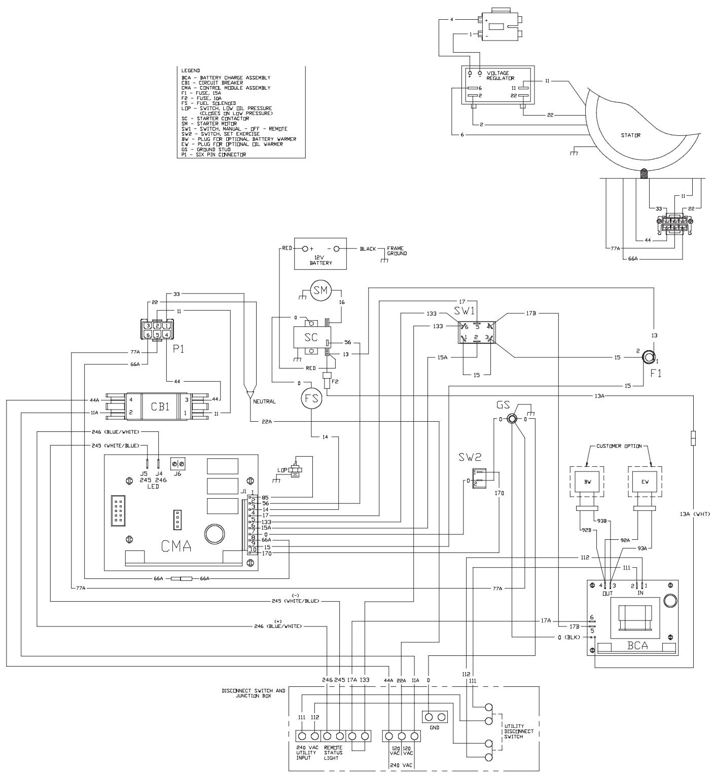
Generator AC Connection System
A single-phase, three-wire AC connection system is used in the Home Standby Generator. The stator assembly consists of a pair of stationary windings with two leads brought out of each winding. The junction of leads 22 and 33 forms the neutral lead. A complete schematic and wiring diagram can be found on pages 26-27.
NOTE: Neutral is not bonded to ground at generator.
Grounding the Generator
Ground the Home Generator System per applicable codes, standards, and regulations. The GND lug is located in the disconnect box.
Generator Control Circuit Connection
Control circuit interconnections consist of "240V AC Utility" leads. These two leads must be routed in conduit. Control lead functions are briefly described as follows:
- Leads deliver utility power to the generator's circuit board, optional battery warmer and oil heater and charge the battery.
Using installer-supplied minimum 300V, 14 AWG copper wire, connect control circuit terminals in the disconnect box to the Transfer Switch.
Remote Diagnostic LED Plate
The light on the remote LED plate is referred to as the Diagnostic LED. The LED will stay lit indicating the generator is in ready mode and will turn on and off in a series of blinks if certain faults are detected in the Home Standby Generator. A mounting plate is supplied so that it can be installed at a convenient indoor location. The owner will use it to observe the status of the Home Standby Generator. Consult with the owner for a convenient location.
To install the remote diagnostic LED plate:
- Mount installer-supplied electrical box to wall.
- Using installer-supplied wire, connect the remote LED leads to the "Remote Status Light" in disconnect box.
NOTE: LED leads are polarity sensitive.
- Attach mounting plate to electrical box.
Refer to the section "Fault Detection System" on pages 21-22 for operation.
BEFORE INITIAL START-UP
Engine Oil
This engine is shipped from the factory filled with the recommended oil. Before starting the engine, check oil level and ensure that engine is serviced as described in the engine operator's manual.
| NOTICE |
| Any attempt to crank or start the engine before it has been properly serviced with the recommended oil will result in equipment failure. |
| ·Refer to engine manual for oil fill information. ·Damage to equipment resulting from failure to follow this instruction will void warranty. |
Oil Considerations
Your Home Standby Generator is equipped with an engine that has been pre-run at the factory and does not require the traditional "break-in" procedure.
The generator is filled with synthetic oil (API SJ/CF 5W-30W). This allows for generator operation in the widest range of temperature and climate conditions.
NOTE: The use of synthetic oil DOES NOT alter the required oil change intervals described in the engine operator's manual.
Battery Connection
The Home Standby Generator is supplied with a 12 Volt DC, AGM type, 33 Amp-Hour, valve regulated battery. It is a sealed, lead-acid rechargeable battery. It is installed in the unit and the battery cables are connected at the factory. The unit's 15 Amp fuse, which isolates the battery and prevents the unit from starting, has been removed for shipping. The battery will lose some charge charge prior to installation of the generator. If battery voltage is below 12 Volts, charge the battery.
IMPORTANT: If battery voltage is below 5 Volts, it may not take a charge and you will need a new battery.
Charging the Battery
If it is necessary to charge the battery, proceed as follows:
- Set the generator's "AUTO/OFF/MANUAL" switch to OFF.
- Remove the 15 Amp fuse from the control panel.
- Disconnect the negative battery cable to the negative battery terminal (indicated by NEGATIVE, NEG, or (-)).
| NOTICE |
| Failure to disconnect negative battery cable will result in equipment failure. |
| ·DO NOT attempt to jump start the battery. ·Damage to equipment resulting from failure to follow this instruction will void warranty. |
- Charge battery with battery charger at 2 Amps until battery holds 12 Volts.
NOTE: DO NOT exceed 13.7 Volts charging.
| WARNING | |
| Storage batteries give off explosive hydrogen gas during recharging. Slightest spark will ignite hydrogen and cause explosion. Battery electrolyte fluid contains acid and is extremely caustic. Contact with battery contents will cause severe chemical burns. A battery presents a risk of electrical shock and high short circuit current. | |
| DO NOT dispose of battery in a fire. DO NOT allow any open flame, spark, heat, or lit cigarette during and for several minutes after charging a battery. DO NOT open or mutilate the battery. Wear protective goggles, rubber apron, and rubber gloves. Remove watches, rings, or other metal objects. Use tools with insulated handles. |
NOTE: With the battery installed and utility power available to the Automatic Transfer Switch, the battery receives a trickle charge whenever the engine is not running. This process may take up to 72 hours to fully charge a battery from 5 Volts. The trickle charge cannot be used to recharge a battery that is completely discharged.
- Connect the negative battery cable to the negative battery terminal (indicated by NEGATIVE, NEG, or (-)).
- Ensure hardware on both positive and negative battery terminals is secure.
- Reinstall the 15 Amp fuse in the control panel.
| CAUTION | |
| Installing the 15A fuse could cause the engine to start. | |
| DO NOT install this fuse until all plumbing and wiring has been completed and inspected. | |
- Set the generator's "AUTO/OFF/MANUAL" switch to AUTO.
Servicing the Battery
If it is necessary to service the battery, proceed as follows:
- Set the generator's "AUTO/OFF/MANUAL" switch to OFF.
- Remove the 15 Amp fuse from the control panel.
- Service or replace battery as required.
- Connect the red battery cable to the battery positive terminal (indicated by POSITIVE, POS, or (+) ).
- Connect the negative battery cable to the negative battery terminal (indicated by NEGATIVE, NEG, or (-)).
- Ensure hardware on both positive and negative battery terminals is secure.
- Reinstall the 15 Amp fuse in the control panel.
- Set the generator's "AUTO/OFF/MANUAL" switch to AUTO.
Fuel Supply System
Ensure that all fuel pipe connections are tight, secure and without leaks.
Ensure that all gas line shutoff valves are OPEN and that adequate fuel pressure is available whenever automatic operation is desired.
FUEL SYSTEM SELECTION
The engine of your Home Standby Generator is factory calibrated to run on natural gas (NG). It may also be operated on liquid propane vapor (LP).
To configure the fuel system for LP use:
- LP fuel inlet pressure must be between 11 and 14 inches water column.
- Set AUTO/OFF/MANUAL switch to OFF.
- Pull service disconnect from disconnect box.
- Remove 15 Amp fuse.
- Change main jet in fuel mixer following instruction sheet provided in LP conversion kit.
- Reinstall 15 Amp fuse.
- Reinstall service disconnect in disconnect box.
- Set AUTO/OFF/MANUAL switch to AUTO.
- Reset exercise timer following instructions "Setting Exercise Timer" on page 20.
The generator is now ready to operate automatically using LP fuel. With a fixed main jet for LP gas, there is no need to perform any engine adjustments for LP operation.
INITIAL START-UP (NO LOAD)
Begin testing the generator without any electrical loads connected, as follows:
- Set AUTO/OFF/MANUAL switch to OFF.
- Set generator's main circuit breaker to OFF (open) position.
- Install 15 Amp fuse in control panel.
- Set AUTO/OFF/MANUAL switch to MANUAL.
NOTE: When the Home Standby Generator is started for the very first time, it will require that air in the gaseous fuel lines be purged. This may take a few minutes.
- DO NOT crank engine for more than 15 seconds, then pause for 15 seconds to reduce heat in starter.
- Repeat process until engine starts.
- Listen for unusual noises, vibration or other indications of abnormal operation. Check for oil leaks while the engine runs.
-
Let engine warm up for about five minutes to allow internal temperatures to stabilize. Then, set generators main circuit breaker to ON (or closed) position.
-
Connect an RMS AC voltmeter and a frequency meter to check generator output at load side of circuit breaker. Voltage should be 230-240 Volts, frequency should be 62.0 - 62.5Hz .
- Check generator output between one generator connection lug and neutral lug, then between other generator connection lug and neutral lug. In both cases, voltage reading should be between 115-120 Volts.
- Set AUTO/OFF/MANUAL switch to OFF. Engine will shut down.
The generator's control panel houses a logic control circuit board. This control board constantly monitors utility power source voltage. Should that voltage drop below a preset level, control board action will signal the engine to crank and start.
When utility source voltage is restored above a preset voltage level, the engine is signaled to shut down.
The actual system operation is not adjustable and is sequenced by sensors and timers on the control board, as follows:
Utility Voltage Dropout Sensor
- This sensor monitors utility source voltage.
- If utility source voltage drops below 70 percent of the nominal supply voltage, the sensor energizes a six second timer.
- Once the timer has expired, the generator will start.
Utility Voltage Pickup Sensor
This sensor monitors utility power supply voltage. When that voltage is restored above 80 percent of the nominal source voltage, a time delay starts timing and the generator will go to engine cool-down.
Engine Cool-down Timer
- When the load is transferred back to the utility power source, the engine cool-down timer starts timing.
- The timer will run for about one minute, then the generator will stop.
- Minimum generator run time is five minutes.
SETTING EXERCISE TIMER
The Home Standby Generator is equipped with an exercise timer that will start and exercise the generator once every seven days. During this exercise period, the unit runs for approximately 20 minutes and then shuts down. Electrical load transfer DOES NOT occur during the exercise cycle (unless an utility power outage occurs).
A switch on the control panel is labeled "Set Exercise" (see page 7). On the specific day and time the switch is pressed, the control board is programmed. This date and time is then used to automatically initiate the generator exercise cycle.
To perform the Set Exercise procedure:
- Choose day and time you want Home Standby Generator to exercise.
- On that day and time, set AUTO/OFF/MANUAL switch to OFF position.
- Press and hold down "Set Exercise" switch for two seconds.
- Set AUTO/OFF/MANUAL switch to AUTO. "Set Exercise" is complete.
For example, if you press the "Set Exercise" switch on Sunday morning at 10:00 AM, the unit will run an exercise cycle the following Sunday at 10:00 AM (+/- 1 hour).
NOTE: "Set Exercise" will only work if the unit is in the Automatic mode and this exact procedure is followed.
If you want to change the day and time the unit exercises, simply perform the "Set Exercise" procedure at the day and time you want it to take place.
INSTALLATION INSPECTION
Before placing the Home Standby Generator into service, inspect the entire installation carefully. Ensure that any scratches or broken paint on the inside or outside of the enclosure are touched up with the supplied paint.
Complete the "Installation Checklist" as you make the inspection. Ensure all items have been filled-in and all signatures have been obtained. Instruct the owner to mail the white copy to:
Briggs & Stratton Power Products
Warranty Registration
P. O. Box 1144
Milwaukee, WI 53201-1144
SPECIFICATIONS
Rated Maximum Power (LP^) 7.0 kW
Rated Maximum Load Current:
at 240 Volts 29.1Amps
at 120 Volts .58.2Amps
Rated AC Voltage 120/240 Volts
Rated Frequency 60 Hz at 3600 rpm
Phase .Single Phase
Power Factor 1.0
NG Fuel Supply Pressure 5-7 in W.C.
LP Fuel Supply Pressure 11-14 in W.C.
Normal Operating Range ..-20°F (-28.8°C) to 104°F (40°C)
Output Sound Level . . . .81 dB(A) at 23 ft. (7 m) at full load
Shipping Weight 280 lbs.
- Natural gas rating will depend on specific fuel but typical derating of generator is between 10 to 20% off the LP gas rating.
AUTOMATIC OPERATION
To select automatic operation, do the following:
- Set service disconnect or main distribution panel circuit breaker that sends utility voltage to transfer switch to ON.
- Set generator's main circuit breaker to ON position.
- Set AUTO/OFF/MANUAL switch to AUTO.
Checking Automatic Operation
To check the system for proper automatic operation, proceed as follows:
- Turn OFF service disconnect or main distribution panel circuit breaker sending power to automatic transfer switch.
The generator will crank and start once the utility voltage drops out and the sensor has timed out. Let the system go through its entire automatic operation sequence.
- With generator output supplying load, turn ON service disconnect or main distribution panel circuit breaker that supplies utility power to automatic transfer switch.
- Automatic transfer switch will transfer loads back to utility power after five minute minimum run time and utility is restored.
- Generator will run for approximately an additional minute for engine cool down, then shut down.
- Install control panel access door and roof following instructions in "Removable Roof and Access Door" on page 12.
NOTE: If generator does not shut down after approximately 10 minutes, put AUTO/OFF/MANUAL switch to OFF and contact your local service center.
This completes the test procedures for automatic operation. The Home Standby Generator will now start automatically when utility power is lost and will supply power to the transfer switch.
Servicing the System
To service system:
- Remove roof by removing four screws and lifting off.
- Remove screw at top of control panel access door.
- Pull access door outward (away) from unit while pulling door upward and out of base. Door will come free of generator enclosure.
- Set AUTO/OFF/MANUAL switch to OFF.
- Set generator's main circuit breaker to OFF position.
- Pull service disconnect from disconnect box.
- Remove 15A fuse from control panel.
FAULT DETECTION SYSTEM
The generator may have to run for long periods of time with no operator present. For that reason, the system is equipped with sensors that automatically shut down the generator in the event of potentially damaging conditions, such as low oil pressure, over speed, and other conditions.
A light on the remote LED plate is called the Diagnostic LED. The LED will turn on and off in a series of blinks if certain problems are detected in your Home Standby Generator. The blink pattern is repeated with a brief pause between each series. The number of blinks in the series indicates the detected fault, as listed on the mounting plate and as follows:
Number of LED Flashes
2
Fault Description
4
Low oil pressure
5
Engine failed to start
6
Low frequency
Section System
Engine overspeed
The operator must reset the fault detection system each time it activates. To do so, place the AUTO/OFF/MANUAL switch in the OFF position for 30 seconds or more. Return the Home Standby Generator to service after correcting the problem by placing the AUTO/OFF/MANUAL switch in the AUTO position.
A description of each fault and suggested remedies are as follows:
No LED - Discharged Battery
This condition is caused by a completely discharged battery. To remedy the problem, remove the 15 Amp fuse and disconnect the battery from the generator. Take the battery to a local battery store for analysis.
Install the battery after it has been fully recharged or replaced, connecting the NEGATIVE cable last. Install the 15 Amp fuse.
Low Oil Pressure
This fault is indicated by two blinks. The generator is equipped with an oil pressure switch (Figure 11). Should oil pressure drop, switch contacts close and the engine is shut down.
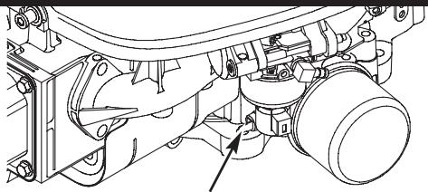
Figure 11—Low Oil Pressure
Oil Pressure Switch
To remedy the low oil pressure condition, add the recommended oil to the FULL mark on the dipstick.
If low oil pressure condition still exists, generator will start, then shut down after approximately 10 seconds and diagnostic LED will flash. In this case, contact your local service center.
Engine Fail To Start
This fault is indicated by four blinks. This feature prevents the generator from damage by continually attempting to start. Each time the system is directed to start, the generator will crank for 15 seconds, pause for 15 seconds, crank for 15 seconds, pause for 15 seconds, and repeat. If the generator does not begin producing electricity after approximately 90 seconds, the generator will stop cranking and the LED will blink.
The most likely cause of this problem is no fuel supply. Check the inside and outside fuel shut off valves to ensure they are fully open. Other causes could be failed spark plug, failed engine ignition, or the engine air filter is clogged. You may need to contact your local service center for assistance if you can't remedy these problems.
Low Frequency
This fault is indicated by five blinks. This feature protects devices connected to the transfer switch by shutting the generator down if the engine runs slower than the preset limit.
This condition may be potentially caused by a failed engine governor. To remedy the problem, you should contact your local service center for assistance.
This condition may also be potentially caused by excessive loads on the generator. Turn off devices one at a time and check the frequency. To remedy the problem, you may need to contact your local service center for assistance.
Engine Overspeed
This fault is indicated by six blinks. This feature protects devices connected to the transfer switch by shutting the generator down if the engine happens to run faster than the preset limit. The overspeed fault is detected as follows:
- If the generator output frequency runs at 72Hz for five seconds, the generator will shut down.
- If the generator output frequency reaches 75Hz , the generator will shut down immediately.
This condition is potentially caused by a failed engine governor. To remedy the problem, you should contact your local service center for assistance.
GENERATOR MAINTENANCE
The generator warranty does not cover items that have been subjected to operator abuse or neglect. To receive full value from the warranty, the operator must maintain the engine as instructed in the engine operator's manual.
IMPORTANT: Before performing any maintenance on the generator, be sure you follow all steps in "Servicing the System" on page 21.
Generator maintenance consists of keeping the unit clean.
Operate the unit in an environment where it will not be exposed to excessive dust, dirt, moisture or any corrosive vapors.
Cooling air louver on the enclosure must not become clog with snow, leaves, or any other foreign material.
Check the cleanliness of the unit frequently and clean when dust, dirt, oil, moisture or other foreign substances are visible on its exterior/interior surface.
NOTE: DO NOT use direct spray from a garden hose to clean generator. Water can enter the engine and generator and cause problems.
Changing Engine Oil and Filter
Remove the two screws from each plastic access cover and remove both access covers from the two sides of the generator enclosure.
Changing Oil
- Place oil drain tube into approved container.
- Push in and rotate oil drain fitting 1/4 turn counterclockwise. Slowly pull outward until oil starts draining (Figure 12). DO NOT pull oil drain fitting off engine.
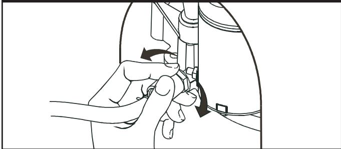
Figure 12 Oil Drain Fitting
- When oil has drained, push oil drain fitting in and rotate 1/4 turn clockwise until it locks in place.
- Slide oil drain tube up into clamp on generator.
Changing Oil Filter
- Place oil drain tray over tubing and slide it under oil filter (Figure 13).
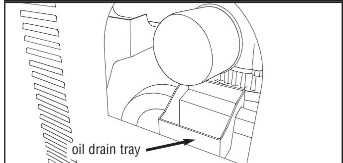
Figure 13 — Changing Oil Filter with Oil Drain Tray
- Follow instructions given in engine operator's manual for changing oil filter.
- Remove oil drain tray from under oil filter and clean up any spilled oil.

CAUTION
Avoid prolonged or repeated skin contact with used motor oil.
- Used motor oil has been shown to cause skin cancer in certain laboratory animals.
- Thoroughly wash exposed areas with soap and water.

KEEP OUT OF REACH OF CHILDREN. DON'T POLLUTE. CONSERVE RESOURCES. RETURN USED OIL TO COLLECTION CENTERS.
To fill your engine with oil:
- Follow synthetic oil grade recommendation given in "Engine Oil" on page 17 and oil fill instructions given in engine operator's manual.
NOTICE
Any attempt to crank or start the engine before it has been properly serviced with the recommended oil will result in equipment failure.
Refer to engine manual for oil fill information.
- Damage to equipment resulting from failure to follow this instruction will void warranty.
To Clean the Generator
- Use a damp cloth to wipe exterior surfaces clean.
| NOTICE |
| Improper treatment of generator can damage it and shorten its life. |
| DO NOT expose generator to excessive moisture, dust, dirt, or corrosive vapors. |
| DO NOT insert any objects through cooling slots. |
- Use a soft, bristle brush to loosen caked on dirt, oil, etc.
- Use a vacuum cleaner to pick up loose dirt and debris.
- Inspect cooling air slots and openings on the generator. These openings must be kept clean and unobstructed.
When Calling the Factory
You must have the following information at hand if it is necessary to contact a local service center regarding service or repair of this unit:
- Obtain unit Model Number and Serial Number from unit data decal. See "Know Your Home Standby Generator" diagram for location.
- Obtain engine Model/Type/Code numbers from engine label. See "Know Your Home Standby Generator" diagram for location. Please note that model number may vary slightly from that presented herein.
STORAGE
The Briggs & Stratton Home Standby Generator is designed for continuous backup operational duty. As such, there is no need to take any storage precautions. However, if it becomes necessary to take the system out of service for an extended period, call Briggs & Stratton Technical Services at 1-800-743-4115, between 8:00 AM and 5:00 PM CT for specific recommendations.
TROUBLESHOOTING
| Problem | Cause | Correction |
| Engine is running, but no AC output is available. | 1. Circuit breaker open or defective. | 1. Reset or replace circuit breaker. |
| 2. Fault in generator. | 2. Contact local service facility. | |
| 3. Poor wiring connections or defective transfer switch. | 3. Check and repair. | |
| Engine runs good at no-load but "bogs down" when loads are connected. | 1. Short circuit in a connected load. | 1. Disconnect shorted electrical load. |
| 2. Generator is overloaded. | 2. See "Essential Circuits". | |
| 3. Shorted generator circuit. | 3. Contact local service facility. | |
| 4. Fuel Pressure is incorrect. | 4. See "The Gaseous Fuel System". | |
| 5. Natural gas fuel mixture is incorrect. | 5. See "The Gaseous Fuel System". | |
| Engine will not start; or starts and runs rough. | 1. 15 Amp fuse missing or blown. | 1. Install (new) 15 Amp fuse. See "Know Your Control Panel". |
| 2. Out of fuel. | 2. Open fuel valve(s); check propane tank. | |
| 3. Battery doesn't have enough power to crank over generator in cold temperatures. | 3. Install battery warmer, contact local service facility. | |
| 4. Failed battery. | 4. Replace battery. | |
| Engine shuts down during operation. | 1. Out of fuel. | 1. Check fuel valves, fill propane tank. |
| 2. Fault indicator blinking. | 2. Count blinks and refer to "Fault Detection System". | |
| Loss of power on essential circuits. | 1. Generator circuit breaker is open. | 1. Reset circuit breaker. |
| 2. Transfer switch problems. | 2. See transfer switch manual. |
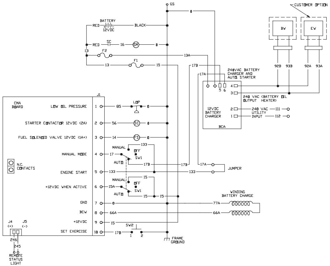
SCHEMATIC
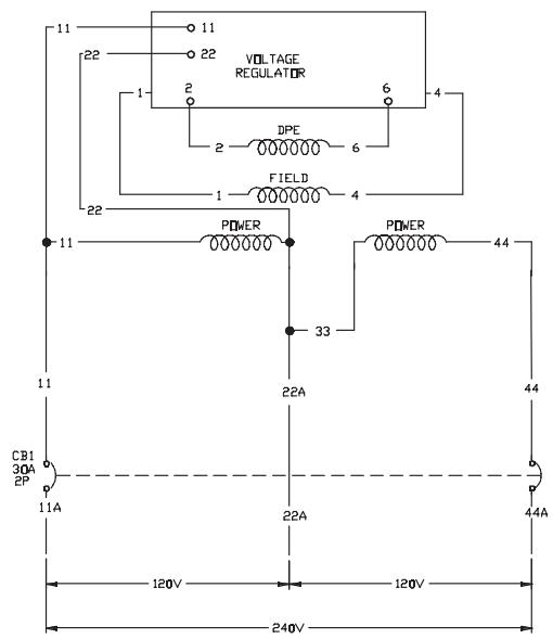
WIRING DIAGRAM
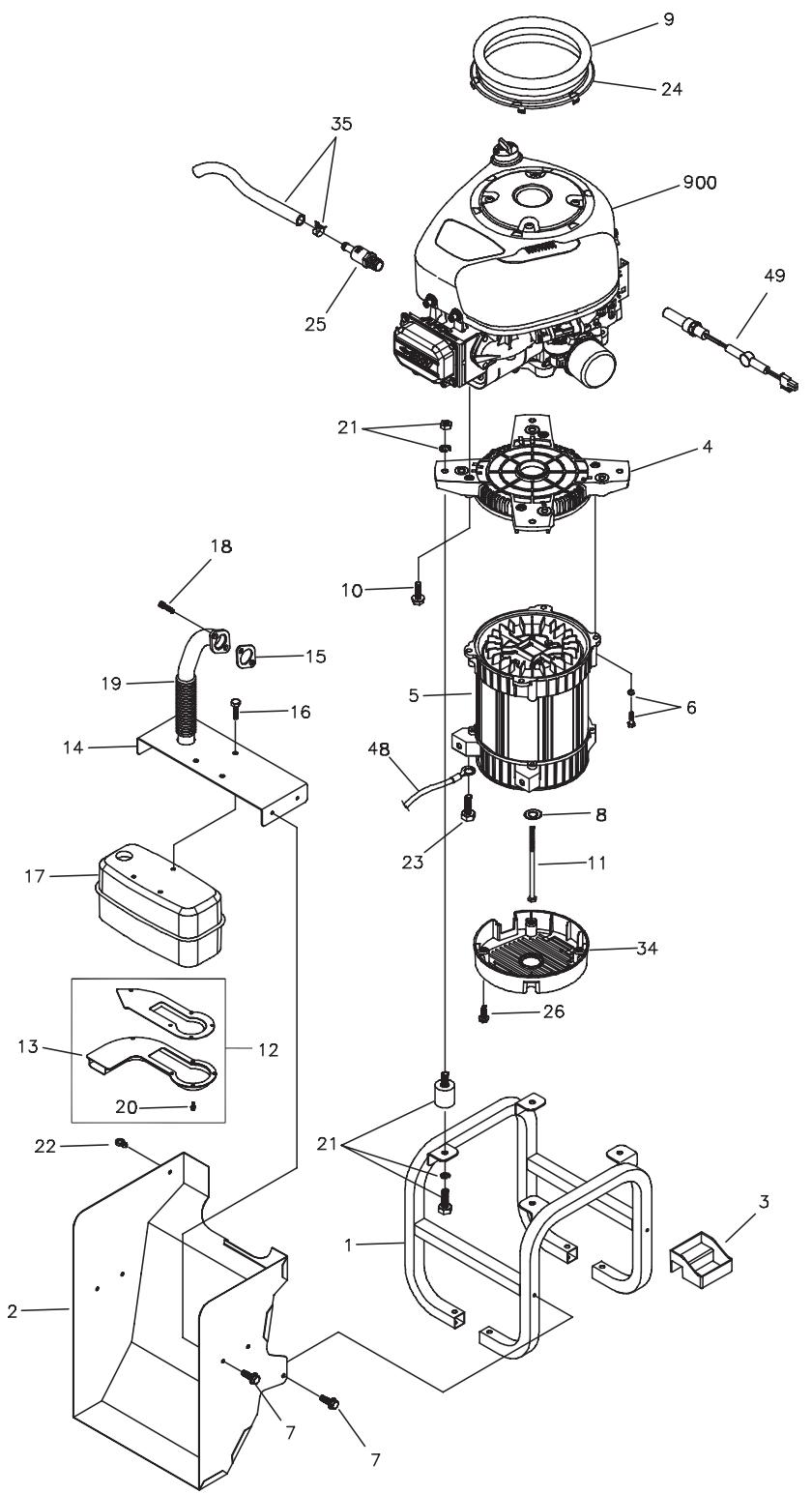
EXPLODED VIEW - MAIN UNIT
PARTS LIST - MAIN UNIT
Item Part #
1 B191860GS
2 194568GS
3 193536GS
4 191793GS
5 NSP
6 194728GS
7*
8 96796GS
9 193012GS
10 75246GS
11 187365HGS
12 194990GS
13 193605GS
14 194569GS
15 692236
16 83512GS
17 193064GS
18 698941
19 194159GS
20 195008GS
21 194209GS
22 192940GS
23*
24 192853GS
25 204025GS
26 74908GS
34 192906GS
35 194992GS
48 15253621GS
49 01916
900 §
Description
WELDMENT, Cradle
ASSY, Duct, Air Muffler
TRAY, Oil Drain
ADAPTER, Engine
ASSY, Alternator (see page 34)
KIT, Hardware Mounting Adapter
BOLT, Swage, 1/4 - 20 x 1/2
WASHER, 8.4 × 22.2 × 3
SEAL, Engine Air Intake
SCREW, 3/8 - 16 x 1-1/4 Taptite
HHCS, 5/16-24 x 9.84
KIT, Deflector Muffler Assy w/Hrdwr
ASSY, Deflector Muffler
BRACKET, Muffler
GASKET
SCREW, M8 1.25 x 15, Taptite
MUFFLER
SCREW, Socket Head Cap
PIPE, Exhaust
KIT, Muffler Hardware
KIT, Vibration Mount
CLIP, Retainer Fuel Hose
HHCS, M6 - 1.0 x 16
COLLAR, Inlet Air
VALVE, Oil Drain
SCREW, M5-.8 x 10 Taptite
COVER Bearing
KIT, Oil Hose w/Clamp
WIRE, Ground
WARMER, Oil
ENGINE
Items Not Illustrated
198838GS
198833GS
194089GS
202295GS
198810GS
194989GS
MS3787
195069GS
196731BGS
MANUAL,Operator's
KIT, Manual/Accessory, ELS
ASSY, Disconnect Box
FLEX HOSE
PAINT, Touchup, Gry
ASSY, Plate Status, Auto
MANUAL, Engine
KIT, CNVRSN, LP
BIT, Screw
Optional Accessories
01915
199474GS
WARMER, Battery
PAINT, Touchup Spray, 12oz, Gry
-
- Items without part numbers are common fasteners and are available at local hardware stores.
§ - Contact Engine Manufacturer
- Items without part numbers are common fasteners and are available at local hardware stores.
EXPLODED VIEW - ENCLOSURE
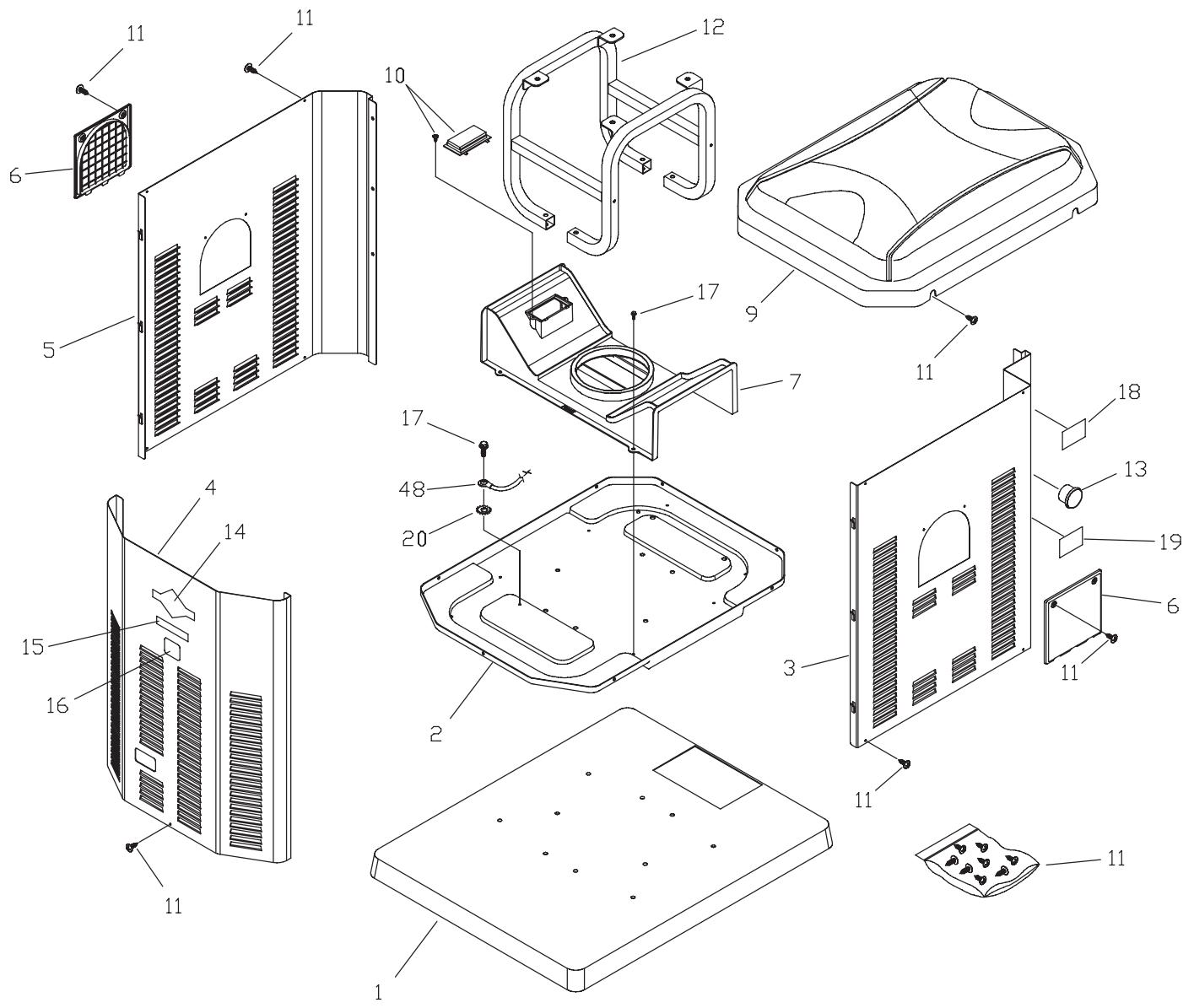
PARTS LIST - ENCLOSURE
Item Part #
1 192441AGS
2 U191852GS
3 198989GS
4 199333GS
5 199335GS
6 199007GS
7 195228GS
9 199009GS
10 194993GS
11 194991GS
12 B191860GS
13 185976GS
14 199296GS
15 200542GS
16 200409GS
17 *
18 195642GS
19 186643GS
20 *
48 195496GS
Description
PAD, ELS
BASE, Plate
ASSY, Panel, Right side
ASSY, Panel, Front
ASSY, Panel, Left Side
COVER, Oil Filter Drain
KIT, Baffle, Air In-take w/Seals
ASSY, Unit Cover
KIT, AVR Circuit Board w/Hrdwr
KIT, Enclosure Hardware Bag
WELDMENT, Cradle
PLUG, Hole
DECAL,Logo
DECAL, Empower
DECAL, Caution Hot
BOLT, Swage, 1/4 - 20 x 1/2
DECAL, Rainproof
DECAL, Fuel Inlet
WASHER, Shakeproof, Ext. M6 - 1/4
WIRE, Ground
-
- Items without part numbers are common fasteners and are available at local hardware stores.
EXPLODED VIEW - CONTROL PANEL
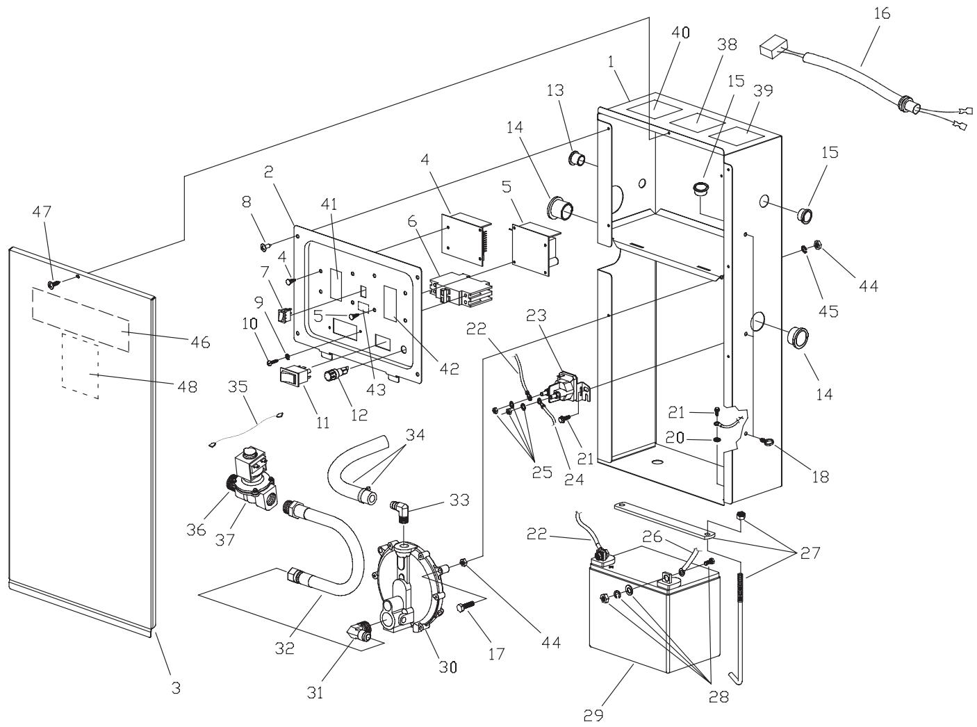
PARTS LIST - CONTROL PANEL
Item Part #
1 195229GS
2 199334GS
3 198990GS
4 195004GS
186413GS
5 195003GS
186413GS
6 190818EGS
7 87799GS
8*
9*
10*
11 193423GS
12 195006GS
13 192455GS
14 186173GS
15 186582GS
16 195007GS
17 *
18 195009GS
20 *
21 *
22 193171GS
23 691656
24 194659GS
25 194251GS
26 188573AGS
Description
ASSY, Control Box
ASSY, Panel, Control
PANEL, Back Cover
KIT, Control Board w/ Clips
Clip, Standoff, Fastex
KIT, Battery Charge Circuit w/ Clips
Clip, Standoff, Fastex
BREAKER, Circuit, 30A
SWITCH, Rocker
SCREW, #10 x 5.8"
WASHER, Shakeproof #6
PPHMS, #6-32×3/8"
SWITCH
KIT, Fuse Holder w/ Fuse
BUSHING, Snap 5/8'
BUSHING, Snap 1-3/8"
BUSHING, Snap 7/8"
KIT, Wire Harness with Crimp Nut
HHCS, M6 - 1.0 x 30
KIT, Plastic Clips
WASHER, Shakeproof, Ext M6 - 1/4
BOLT, Swage, 1/4 - 20 x 1/2
ASSY, Wire, 6AWG, Red
CONTACTOR, Starter
ASSY, Wire, 6AWG, Red
KIT, Hardware Starter Contact
ASSY, Wire, Series w/2 Ring Lug
Item Part #
27 199844GS
28 193347GS
29 188443GS
30 193291GS
31 186151GS
32 186148GS
33 186150GS
34 195005GS
35 193537CGS
36 192449GS
37 B4773GS
38 186646GS
39 186647GS
40 190992GS
41 186645GS
42 195306GS
43 B4986AGS
44 *
45*
46 186641GS
47*
48 202896GS
Description
KIT, J-Bolt/Strap with Hardware
KIT, Battery Hardware
BATTERY
REGULATOR, Fuel
FITTING, Elbow, 3/4 NPT
HOSE, Gas, Reg. to Valve
FITTING, Elbow, 3/8 NPT
KIT, Hose, Reg to Engine with Clamps
WIRE, 18 AWG, Blue
FITTING, Nipple, 3/4 × 2
SOLENOID, Gas Fuel
DECAL, Warning, Auto Start
DECAL, Warning, Outdoor Install
DECAL, Warning Electrical Shock
DECAL, Caution, Shock
DECAL, Set Exercise Timer
DECAL, Ground
NUT, M6 - 1.0
LOCKWASHER, 1/4
DECAL, Operating Instructions
SCREW, 10 x 32 x 1 Phillips Truss Head
DECAL, Fuel Requirements
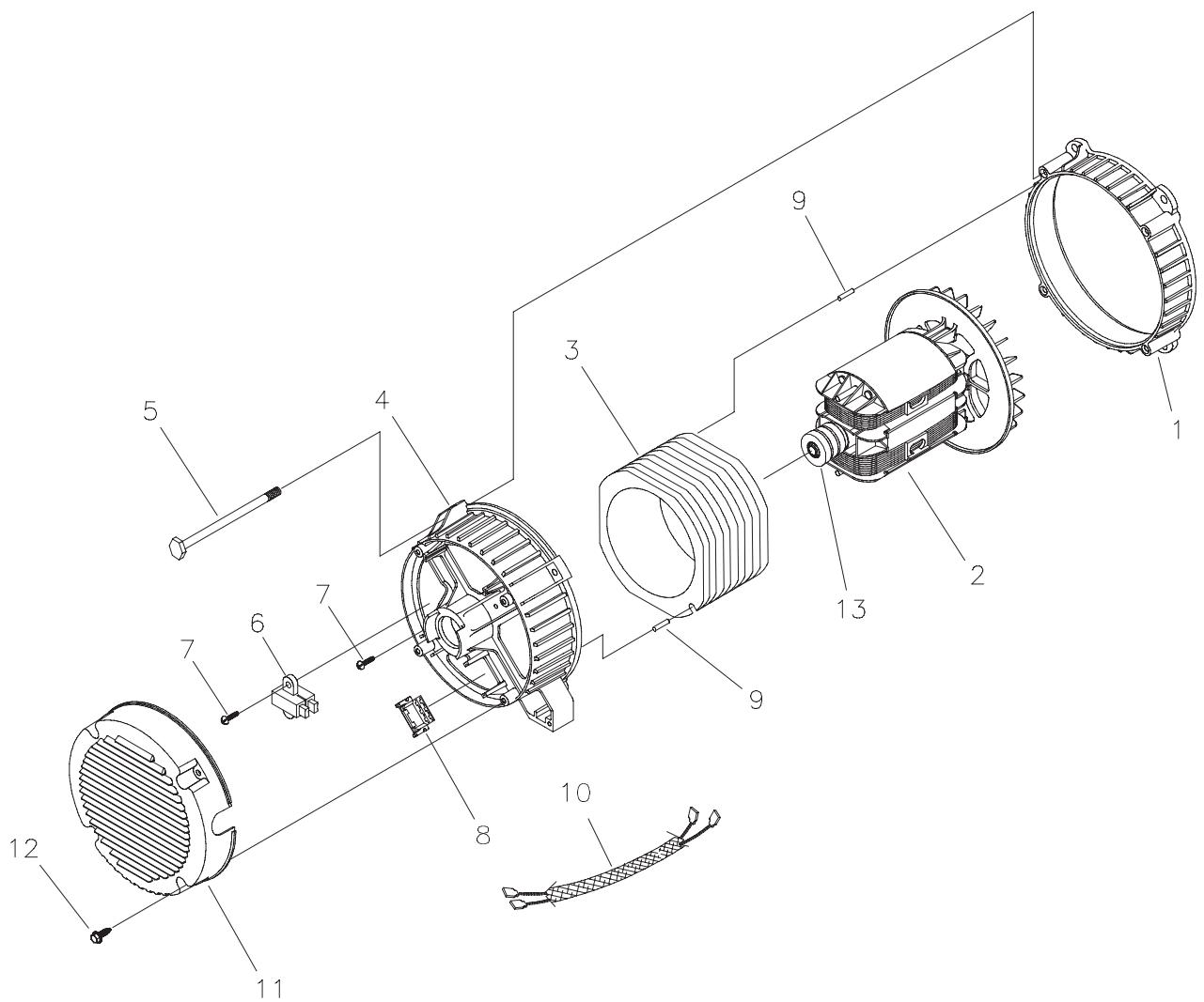
EXPLODED VIEW AND PARTS LIST - ALTERNATOR
Item Part #
1 186059GS
2 195430GS
3 193091AGS
4 193336GS
5 86308KGS
6 66386GS
7 66849GS
8 22694GS
9 81917GS
10 193472GS
11 192906GS
12 74908GS
13 65791GS
Description
ADAPTER, Mounting, Alternator
ROTOR (Includes Item 13)
STATOR
RBC, (with O-Ring p/n 189197GS)
HHCS, M6 - 1.0 x 140 SEMS
ASSY, Holder, Brush
TAPTITE, M5 - 0.8 x 16
RECEPTACLE,6 pin
PIN, Roll, 4mm x 10
HARNESS, Wire DC Charge
COVER, Bearing
SCREW, M5 - .8 x 10 Taptite
BEARING
Effective September 1, 2005 replaces all undated Warranties and all Warranties dated before September 1, 2005
LIMITED WARRANTY
Briggs & Stratton Power Products Group, LLC will repair or replace, free of charge, any part(s) of the equipment that is defective in material or workmanship or both. Transportation charges on product submitted for repair or replacement under this warranty must be borne by purchaser. This warranty is effective for the time periods and subject to the conditions stated below. For warranty service, find the nearest Authorized Service Dealer in our dealer locator map at BRIGGSandSTRATTON.COM.
THERE IS NO OTHER EXPRESS WARRANTY. IMPLIED WARRANTYES, INCLUDING THOSE OF MERCHANTABILITY AND FITNESS FOR A PARTICULAR PURPOSE, ARE LIMITED TO ONE YEAR FROM PURCHASE, OR TO THE EXTENT PERMITTED BY LAW. ANY AND ALL IMPLIED WARRANTYES ARE EXCLUDING. LIABILITY FOR INCIDENTAL OR CONSEQUENTIAL DAMAGES ARE EXCLUDING TO THE EXTENT EXCLUSION IS PERMITTED BY LAW. Some states or countries do not allow limitations on how long an implied warranty lasts, and some states or countries do not allow the exclusion or limitation of incidental or consequential damages, so the above limitation and exclusion may not apply to you. This warranty gives you specific legal rights and you may also have other rights which vary from state to state or country to country.
WARRANTY PERIOD
Consumer Use 2 years
Commercial Use None
The warranty period begins on the date of purchase by the first retail consumer or commercial end user, and continues for the period of time stated in the table above. "Consumer use" means personal residential household use by a retail consumer. "Commercial use" means all other uses, including use for commercial, income producing or rental purposes. Once equipment has experienced commercial use, it shall thereafter be considered as commercial use for purposes of this warranty.
NO WARRANTY REGISTRATION IS NECESSARY TO OBTAIN WARRANTY ON BRIGGS & STRATTON PRODUCTS. SAVE YOUR PROOF OF PURCHASE RECEIPT. IF YOU DO NOT PROVIDE PROOF OF THE INITIAL PURCHASE DATE AT THE TIME WARRANTY SERVICE IS REQUESTED, THE MANUFACTURING DATE OF THE PRODUCT WILL BE USED TO DETERMINE THE WARRANTY PERIOD.
ABOUT YOUR WARRANTY
We welcome warranty repair and apologize to you for being inconvenienceed. Any Authorized Service Dealer may perform warranty repairs. Most warranty repairs are handled routinely, but sometimes requests for warranty service may not be appropriate. For example, warranty service would not apply if equipment damage occurred because of misuse, lack of routine maintenance, shipping, handling, warehousing or improper installation. Similarly, the warranty is void if the manufacturing date or the serial number on the equipment has been removed or the equipment has been altered or modified. During the warranty period, the Authorized Service Dealer, at its option, will repair or replace any part that, upon examination, is found to be defective under normal use and service. This warranty will not cover the following repairs and equipment:
- Normal Wear: Outdoor Power Equipment and engines, like all mechanical devices, needs periodic parts and service to perform well. This warranty does not cover repair when normal use has exhausted the life of a part or the equipment.
Installation and Maintenance: This warranty does not apply to equipment or parts that have been subjected to improper or unauthorized installation or alteration and modification, misuse, negligence, accident, overloading, overspeeding, improper maintenance, repair or storage so as, in our judgment, to adversely affect its performance and reliability. This warranty also does not cover normal maintenance such as adjustments, fuel system cleaning and obstruction (due to chemical, dirt, carbon, lime, etc.).
Other Exclusions: This warranty excludes wear items such as oil gauges, o-rings, filters, fuses, spark plugs, etc., or damage or malfunctions resulting from accidents, abuse, modifications, alterations, or improper servicing or freezing or chemical deterioration. Accessory parts are excluded from the product warranty. This warranty excludes failures due to acts of God and other force majeure events beyond the manufacturers control. Also excluded is used, reconditioned, and demonstration equipment; equipment used for prime power in place of utility power and equipment used in life support applications. 198182E, Rev. D, 12/31/2006
TABLE DE CONTENTIDO
TABLE DE CONTENIDO 36
Briggs & Stratton Power Products
Warranty Registration
P. O. Box 1144
Milwaukee, Wisconsin 53201-1144
ESPECIFICACIONES
Potencia Nominal Maxima 7,000 Vatios
Corrente de Carga Nominal Maxima:
a 240 Voltios .29.1 Amperios
a 120 Voltios .58.3 Amperios
Tensión de c.a. Nominal 120/240 Voltios
Frecuencia Nominal .60 Hz at 3600 rpm
Fases .Monofasico
Briggs & Stratton Power Products
Warranty Registration
P. O. Box 1144
Milwaukee, Wisconsin 53201-1144
CHARACTERISTIQUES
Puisance Nominale Maximum (PL^) 7,000 Watts
Charge Nominale Maximum:
a 240 Volts 29.1 Ampères
Tension Nominate C.A. 120/240 Volts
- Rated Watts Home Generator System
- Installation, Start-Up and Operator's Manual Manual de Instalación, Arranque y Operario Manuel d'Installation, Demarrage et Utilisation
- SAVE THESE INSTRUCTIONS
- IMPORTANT SAFETY INSTRUCTIONS
- Hazard Symbols and Meanings
- WARNING
- KNOW YOUR HOME STANDBY GENERATOR
- Read this Operator's Manual and safety rules before operating your generator.
- KNOW YOUR CONTROL PANEL
- INTRODUCTION
- CUSTOMER RESPONSIBILITIES
- INSTALLER RESPONSIBILITIES
- INSTALLATION ASSISTANCE
- Read and understand the Owner Orientation Section of this manual BEFORE contracting or starting your Home Standby Generator installation.
- The Home Standby Generator Warranty is VOID unless the generator is installed by licensed electrical and plumbing professionals.
- For the Installing Dealer/Contractor:
- OWNER ORIENTATION
- The factors mentioned above will have a direct effect on the overall price of your Home Standby Generator installation.
- Fuel Factors
- Power Decrease at High Altitude or High Temperature
- INSTALLATION PROCEDURES
- Unpacking Precautions
- Delivery Inspection
- Approved Transfer Switches
- Shipment Contents
- The Home Standby Generator is supplied with:
- Lifting the Generator
- Home Standby Generator Location
- Generator Clearances
- General Location Guidelines
- Essential Circuits
- Essential Circuit Selection
- This Briggs & Stratton Home Standby Generator complies with the following "stationary standby power rating":
- Disconnect Box Mounting Guidelines
- Fuel Inlet Dimensions
- Removable Roof and Access Door
- To Remove Roof:
- To Remove Access Door:
- To Install Access Door and Roof:
- THE GASEOUS FUEL SYSTEM
- CAUTION
- Consider the following factors when planning to install the fuel supply system:
- Fuel Consumption
- Fuel Pipe Sizing
- Size of Propane Tank Required at Various Temperatures When Kept at Least Half Full
- WIRE CONNECTIONS
- Recommended Torque Values
- Generator AC Connection System
- Grounding the Generator
- Generator Control Circuit Connection
- Remote Diagnostic LED Plate
- To install the remote diagnostic LED plate:
- BEFORE INITIAL START-UP
- Engine Oil
- Oil Considerations
- Battery Connection
- Charging the Battery
- Servicing the Battery
- Fuel Supply System
- FUEL SYSTEM SELECTION
- To configure the fuel system for LP use:
- INITIAL START-UP (NO LOAD)
- Utility Voltage Dropout Sensor
- Utility Voltage Pickup Sensor
- Engine Cool-down Timer
- SETTING EXERCISE TIMER
- To perform the Set Exercise procedure:
- INSTALLATION INSPECTION
- SPECIFICATIONS
- AUTOMATIC OPERATION
- Checking Automatic Operation
- Servicing the System
- FAULT DETECTION SYSTEM
- Number of LED Flashes
- Fault Description
- Section System
- No LED - Discharged Battery
- Low Oil Pressure
- Engine Fail To Start
- Low Frequency
- Engine Overspeed
- GENERATOR MAINTENANCE
- Changing Engine Oil and Filter
- Changing Oil
- Changing Oil Filter
- To fill your engine with oil:
- NOTICE
- To Clean the Generator
- When Calling the Factory
- STORAGE
- SCHEMATIC
- WIRING DIAGRAM
- PARTS LIST - MAIN UNIT
- Item Part #
- Description
- Items Not Illustrated
- Optional Accessories
- EXPLODED VIEW - ENCLOSURE
- PARTS LIST - ENCLOSURE
- EXPLODED VIEW - CONTROL PANEL
- PARTS LIST - CONTROL PANEL
- LIMITED WARRANTY
- WARRANTY PERIOD
- ABOUT YOUR WARRANTY
- TABLE DE CONTENTIDO
- ESPECIFICACIONES
- CHARACTERISTIQUES
Brand : BRIGGS & STRATTON
Model : BRIGGS & STRATTON 7000 WATT GENERATOR SYSTEM
Category : Electric generator