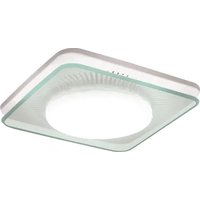
LunAura QTNLEDB - Fan NuTone - Free user manual and instructions
Find the device manual for free LunAura QTNLEDB NuTone in PDF.


| Product type | Ceiling fan with LED lighting |
| Brand | NuTone |
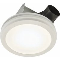
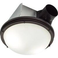
| Model | LunAura QTNLEDB |
| Diameter | 52 inches (132 cm) |
| Weight | Approx. 5.2 kg |
| Power supply | 120 V, 60 Hz |
| Motor power | 120 W |
| Lighting | Integrated LED (15 W) |
| Number of speeds | 5 speeds |
| Reverse function | Yes (summer/winter) |
| Remote control | Included, range 10 m |
| Mounting | Ceiling, tilt up to 15° |
| Rod height | 15 cm (standard) |
| Blade material | Lacquered MDF |
| Color | White or black (depending on version) |
| Noise level | 35 dB (low speed) |
| Airflow | 6500 m³/h max |
| Certification | UL, cUL |
| Warranty | 2 years |
| Maintenance | Wipe with a soft dry cloth |
| Spare parts | Available on order |
Frequently Asked Questions - LunAura QTNLEDB NuTone
User questions about LunAura QTNLEDB NuTone
0 question about this device. Answer the ones you know or ask your own.
Ask a new question about this device
Download the instructions for your Fan in PDF format for free! Find your manual LunAura QTNLEDB - NuTone and take your electronic device back in hand. On this page are published all the documents necessary for the use of your device. LunAura QTNLEDB by NuTone.
USER MANUAL LunAura QTNLEDB NuTone
READ AND SAVE THESE INSTRUCTIONS
WARNING


TO REDUCE THE RISK OF FIRE, ELECTRIC SHOCK, OR INJURY TO PERSONS, OBSERVE THE FOLLOWING:
- Use this unit only in the manner intended by the manufacturer. If you have questions, contact the manufacturer at the address or telephone number listed in the warranty.
- Before servicing or cleaning unit, switch power off at service panel and lock the service disconnecting means to prevent power from being switched on accidentally. When the service disconnecting means cannot be locked, securely fasten a prominent warning device, such as a tag, to the service panel.
- Installation work and electrical wiring must be done by a qualified person(s) in accordance with all applicable codes and standards, including fire-rated construction codes and standards.
- Sufficient air is needed for proper combustion and exhausting of gases through the flue (chimney) of fuel burning equipment to prevent backdrafting. Follow the heating equipment manufacturer's guideline and safety standards such as those published by the National Fire Protection Association (NFPA), and the American Society for Heating, Refrigeration and Air Conditioning Engineers (ASHRAE), and the local code authorities.
- When cutting or drilling into wall or ceiling, do not damage electrical wiring and other hidden utilities.
- Ducted fans must always be vented to the outdoors.
- Acceptable for use over a tub or shower when connected to a GFCI (Ground Fault Circuit Interrupter) - protected branch circuit.
- This unit must be grounded.
CAUTION

- For general ventilating use only. Do not use to exhaust hazardous or explosive materials and vapors.
- This product is designed for installation in ceilings up to a 12/12 pitch (45 degree angle). Duct connector must point up. DO NOT MOUNT THIS PRODUCT IN A WALL.
- To avoid motor bearing damage and noisy and/or unbalanced impellers, keep drywall spray, construction dust, etc. off power unit.
- The LED light source is designed for this specific application and can overheat if serviced by untrained personnel. If any servicing is required, the product should be returned to an authorized service facility for examination or repair.
- Please read specification label on product for further information and requirements.
CLEANING & MAINTENANCE
For quiet and efficient operation, long life, and attractive appearance - lower or remove grille and vacuum interior of unit with the dusting brush attachment.
To clean the LED plate:
- Remove grille from ceiling and unplug wiring from housing.
- Remove lens.
- Remove three (3) screws from retention ring.
- Remove LED plate and wash plate with a mild detergent solution.
DO NOT USE ABRASIVE CLOTH, STEEL WOOL PADS, SCOURING POWDERS, CLEANING SPRAYS OR SOLVENTS.
- Re-assemble grille assembly and re-install to fan housing.

The motor is permanently lubricated and never needs oiling. If the motor bearings are making excessive or unusual noises, replace the blower assembly (includes motor and impeller).
OPERATION
The fan, light, and night light can be operated separately. Use a 3-function wall control. Do not use a dimmer switch to operate the light. See "Connect Wiring" for details. Use of speed controls other than the NuTone Models 78V and 78W may cause a motor humming noise.
Register your product online at: www.nutone.com/register
Installer: Leave this manual with the homeowner.
TYPICAL INSTALLATIONS

Housing mounted to I-joists.
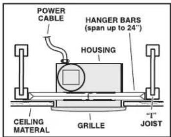
Housing mounted anywhere between I-joists using hanger bars.
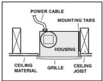
Housing mounted to joists.
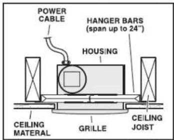
Housing mounted anywhere between joists using hanger bars.
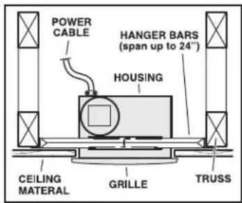
Housing mounted anywhere between trusses using hanger bars.

Housing mounted anywhere between trusses using hanger bars.
PLAN THE INSTALLATION

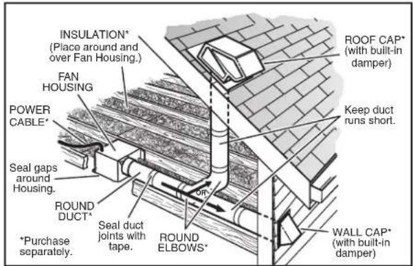
The ducting from this fan to the outside of the building has a strong effect on the air flow, noise and energy use of the fan. Use the shortest, straightest duct routing possible for best performance, and avoid installing the fan with smaller ducts than recommended. Insulation around the ducts can reduce energy loss and inhibit mold growth. Fans installed with existing ducts may not achieve their rated airflow.
6-inch round rigid metal duct is recommended for best performance.
Use a roof cap or wall cap that has a built-in damper to reduce backdrafts.
Plan to supply the unit with proper line voltage and appropriate power cable.
INSTALL HOUSING & DUCT
1a. Mount housing to joist or I-joist.
Use a pliers to bend housing
TABS out to 90°. Hold
housing in
place so that
the housing
tabs contact
the bottom of the joint
of the Joist.
The housing
mounts with
tour (4) screws
or nails. Screw
or nail housing
to joist through
lowest holes in
each mountin
flange, then
through
highest holes.


NOTE: Mounting to I-JOIST (shown) requires use of SPACERS (included) between the highest hole of each mounting flange and the 1-joist.
1b. Mount housing anywhere between trusses, joists, or I-joists using hanger bars.
Sliding hanger bars are provided to allow for accurate positioning of housing anywhere between framing. They can be used on all types of framing (1-joist, standard joist, and truss construction) and span up to 24".
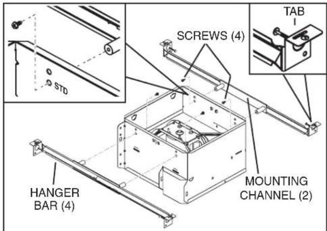
Attach the MOUNTING CHANNELS to the housing using the SCREWS supplied. Make sure TABS face "up" as shown. Use the set of channel mounting holes (marked "STD") to mount the housing flush with the bottom of the drywall. Use the other set of holes (not marked) to mount the housing flush with the top of the drywall.

Extend HANGER BARS to the width of the framing.
Hold ventilator in place with the hanger bar tabs wrapping around the BOTTOM EDGE OF THE FRAMING.
NAIL ventilator to framing or fasten with screws (not provided) through HOLES near nails.
* To ensure a noise-free mount: Secure hanger bars together with SCREWS or use a pliers to crimp mounting channels tightly around hanger bars.
2. Attach damper/duct connector.
Snap damper / duct connector onto housing. Make sure connector is flush with top of housing and damper flap falls closed.

3. Install 6-inch or 4-inch round ductwork.
Connect 6-inch or 4-inch round ductwork to damper / duct connector or reducer. Run ductwork to a roof cap or wall cap.
Tape all ductwork

connections to make them secure and air tight.
CONNECT WIRING
![graph TD A["LIGHT SWITCH"] --> B["BRIDGE"] C["LED NIGHT LIGHT SWITCH"] --> D["BRIDGE"] E["FAN SWITCH"] --> F["BRIDGE"] G["LINE IN"] --> H["GRD"] I["SWITCH BOX"] --> J["UNIT"] K["BLK"] --> L["RED"] M["BLK"] --> N["RED"] O["BLK"] --> P["RED"] Q["BLK"] --> R["RED"] S["BLK"] --> T["RED"] U["BLU"] --> V[…](/content/2026/07/1439376/images/96f4fc40fbab6cf5daeb0e9724e7032b080dff573d15912bee32bfee91b02209.jpg)

4. Connect electrical wiring.
Run 120 VAC house wiring to installation location. Use proper UL approved connector to secure house wiring to wiring plate. Connect wires as shown in wiring diagrams.
INSTALL GRILLE
5. Finish ceiling.
Install ceiling material. Cut out around housing.
6. Plug in wiring.
Plug wiring into proper receptacles.
7. Attach grille to housing.
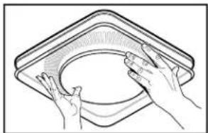
Squeeze grille springs and insert them into tabs on each side of housing.
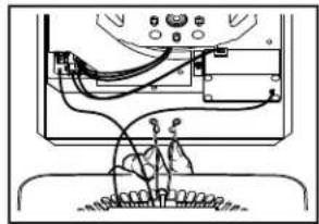
8. Push grille against ceiling.

9. Remove light lens.
Carefully insert a small flat-blade screwdriver between grille and lens. Pry lens out.

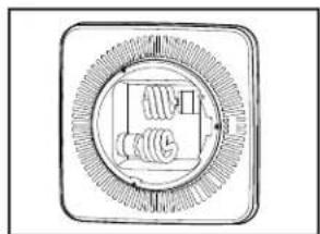
10. Install light bulbs.
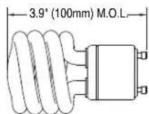
Purchase (2) 18W (max.), type GU24 fluorescent lamps with M.O.L. (maximum overall length) of 3.9" (100mm) as illustrated below.
Insert lamps and bulb into their sockets. Replace lens.
WARRANTY
BROAN-NUTONE THREE YEAR LIMITED WARRANTY
Broan-No-Tone warrants to the original consumer purchaser of its products that such products will be free from defects in materials or workmanship for a period of three years from the date of original purchase. THERE ARE NO OTHER WARRANTIES, EXPRESS OR IMPLIED, INCLUDING, BUT NOT LIMITED TO, IMPLIED WARRANTIES OF MERCHANTABILITY OR FITNESS FOR A PARTICULAR PURPOSE.
During this three-year period, Broan-NuTone will, at its option, repair or replace, without charge, any product or part which is found to be defective under normal use and service.
THIS WARRANTY DOES NOT EXTEND TO FLUORESCENT LAMP STARTERS, TUBES, HALOGEN AND INCANDESCENT BULBS, FUSES, FILTERS, DUCTS, ROOF CAPS, WALL CAPS AND OTHER ACCESSORIES FOR DUCTING. This warranty does not cover (a) normal maintenance and service or (b) any products or parts which have been subject to misuse, negligence, accident, Improper maintenance or repair (other than by Broan-NuTone), faulty installation or installation contrary to recommended installation instructions.
The duration of an implied warranty is limited to the three-year period as specified for the express warranty. Some states do not allow limitation on how long an implied warranty lasts, so the above limitation may not apply to you.
BROWN-NUTONE'S OBLIGATION TO REPAIR OR REPLACE. AT BROWN-NUTONE'S OPTION, SHALL BE THE PURCHASER'S SOLE AND EXCLUSIVE REMEDY UNDER THIS WARRANTY. BROWN-NUTONE SHALL NOT BE LIABLE FOR INCIDENTAL, CONSEQUENTIAL, OR SPECIAL DAMAGES ARISING OUT OF OR IN CONNECTION WITH PRODUCT USE OR PERFORMANCE. Some states do not allow the exclusion or limitation of incidental or consequential damages, so the above limitation may not apply to you.
This warranty gives you specific legal rights, and you may also have other rights, which vary from state to state. This warranty supersedes all prior warranties.
To qualify for warranty service, you must (a) notify Broan-Nu Tone at the address or telephone number stated below. (b) give the model number and part identification and (c) describe the nature of any defect in the product or part. At the time of requesting warranty service, you must present evidence of the original purchase date.
Brcan-NuTone LLC, 926 W. State Street, Hartford, Wisconsin 53027 www.nutone.com 888-336-3948
DIAGONAL LED PLATE OPTION
To rotate LED plate to diagonal position:
- Remove grille from ceiling and unplug wiring from housing.
- Remove lens.
- Remove three (3) screws from retention ring.
- Remove LED plate and rotate plate clockwise to diagonal position.
- Re-assemble grille assembly and re-install to fan housing.

SERVICE PARTS

Replacement parts can be ordered on our website. Please visit us at www.nutone.com
SERVICE NOTE
To remove Blower Assembly: Unplug motor. Remove thumbscrew (11) from motor plate flange. Find the single TAB on the motor plate (located next to the receptacle). Push up near motor plate tab while pushing out on side of housing. Or insert a straight-blade screwdriver into slot in housing (next to tab) and twist screwdriver.
| KEY NO. | PART NO. | DESCRIPTION |
| 1 SQTHB1 | HANGER BAR KIT | |
| 2 475 | DUCT REDUCER 6" TO 4" | |
| 3 97018 | 662 DUCT CONNECTOR - 6" | |
| 4 99111 | 293 SPACER (2 REQ'D) | |
| 5 97016 | 466 HOUSING | |
| 6 98010 | 102 WIRING PLATE | |
| 7 99170 | 245 SCREW, #8-18 X .375 | |
| 8 97018 | 552 WIRE PANEL/HARNESS ASSEMBLY | |
| 9 97020 | 045 CONTROL ASSEMBLY | |
| 10 97020 | 046 SERVICE ASSEMBLY, BLOWER(INCLUDES KEY NO. 11) | |
| 11 99420 | 665 THUMBSCREW, #8-18 X .375 | |
| 12 99140 | 199 GRILLE SPRING (2 REQ'D) | |
| 13 97018 | 561 GRILLE ASSEMBLY | |
| 14 99271 | 881 BULB, GU24, 18W FLUORESCENT (2 REQ'D) | |
| 15 99111 | 532 RING | |
| 16 99111 | 529 LENS |
* Not shown assembled.
Order service parts by "Part No." - not by "Key No."
VENTILATEUR / LUMIÈRE / VEILLEUSE DEL MODÈLE QTNLEDB

LIRE CES DIRECTIVES ET LES CONSERVER
AVERTISSEMENT


AFIN DE DIMINUER LES RISQUES D'INCENDIE, D'ÉLECTROCUTION OU DE BLESSURES, SUIVEZ CES DIRECTIVES :
GARANTIE

GARANTIE LIMITÉE DE TROIS ANS DE BROAN-NUTONE
Página 9
LEA Y CONSERVE ESTAS INSTRUCCIONES
ADVERTENCIA

PARA REDUCIR EL RIESGO DE INCENDIO, DESCARGA ELÉCTRICA O LESIONES CORPORALES, OBSERVE LO SIGUIENTE:
3. Instale conductos redondos de 6 ó 4 pulgadas (15.2 ó 10.2 cm).
CONEXIÓN ELÉCTRICA
![graph TD A["INTERRUPTOR DE LUZ"] --> B["LIÑEA DE ENTRADA"] C["INTERRUPTOR DE LA LUZ NOCTURNA DE LED"] --> B D["INTERRUPTOR DEL VENTILADOR"] --> B E["TIERRA"] --> B B --> F["CAJA DEL INTERRUPTOR"] B --> G["TIERRA"] H["NEGRO"] --> I["BLANCO"] J["ROJO"] --> K["BLANCO"] L["NEGRO NEGRO"] --> M["BLANCO"]…](/content/2026/07/1439376/images/204493873b875b038ea811aa81273da697d5a5780699acaaae8fe62fd096f5c9.jpg)


Broen-NuTone LLC, 926 W. State Street, Hartford, Wisconsin 53027 www.nutone.com 888-336-3948


- READ AND SAVE THESE INSTRUCTIONS
- WARNING
- TO REDUCE THE RISK OF FIRE, ELECTRIC SHOCK, OR INJURY TO PERSONS, OBSERVE THE FOLLOWING
- CAUTION
- CLEANING & MAINTENANCE
- TO CLEAN THE LED PLATE
- OPERATION
- INSTALLER: LEAVE THIS MANUAL WITH THE HOMEOWNER
- TYPICAL INSTALLATIONS
- PLAN THE INSTALLATION
- INSTALL HOUSING & DUCT
- 1A. MOUNT HOUSING TO JOIST OR I-JOIST
- 1B. MOUNT HOUSING ANYWHERE BETWEEN TRUSSES, JOISTS, OR I-JOISTS USING HANGER BARS
- ATTACH DAMPER/DUCT CONNECTOR
- INSTALL 6-INCH OR 4-INCH ROUND DUCTWORK
- CONNECT WIRING
- CONNECT ELECTRICAL WIRING
- INSTALL GRILLE
- FINISH CEILING
- PLUG IN WIRING
- ATTACH GRILLE TO HOUSING
- PUSH GRILLE AGAINST CEILING
- REMOVE LIGHT LENS
- INSTALL LIGHT BULBS
- WARRANTY
- BROAN-NUTONE THREE YEAR LIMITED WARRANTY
- DIAGONAL LED PLATE OPTION
- TO ROTATE LED PLATE TO DIAGONAL POSITION
- SERVICE PARTS
- SERVICE NOTE
- VENTILATEUR / LUMIÈRE / VEILLEUSE DEL MODÈLE QTNLEDB
- LIRE CES DIRECTIVES ET LES CONSERVER
- AVERTISSEMENT
- GARANTIE
- LEA Y CONSERVE ESTAS INSTRUCCIONES
- ADVERTENCIA
- PARA REDUCIR EL RIESGO DE INCENDIO, DESCARGA ELÉCTRICA O LESIONES CORPORALES, OBSERVE LO SIGUIENTE
- INSTALE CONDUCTOS REDONDOS DE 6 Ó 4 PULGADAS (15.2 Ó 10.2 CM)
- CONEXIÓN ELÉCTRICA
Brand : NuTone
Model : LunAura QTNLEDB
Category : Fan