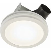
Roomside AERN80LWH - Fan NuTone - Free user manual and instructions
Find the device manual for free Roomside AERN80LWH NuTone in PDF.


| Product Type | Bathroom fan / air extractor |
| Brand | NuTone |
| Model | Roomside AERN80LWH |
| Color | White |
| Material | ABS plastic and metal |
| Dimensions (L x W x H) | 305 x 305 x 230 mm |
| Duct diameter | 200 mm (8 inches) |
| Net weight | 2.7 kg |
| Power supply | 120 V ~ 60 Hz |
| Power | 50 W |
| Maximum airflow | 180 m³/h (CFM 106) |
| Noise level | 1.5 sones (low) |
| Main functions | Air extraction, quiet, easy to install |
| Control | Wall switch (not included) |
| Mounting type | Wall or ceiling |
| Maintenance and cleaning | Unplug before cleaning. Clean the blades and grille with a damp cloth. Do not use abrasive products. |
| Safety | Unplug before any intervention. Do not immerse in water. |
| Spare parts | Grille, motor, blades, switch (available on the manufacturer's website) |
| Repairability | Repairability index: 7.5/10 (accessible parts) |
| Warranty | 1 year |
| Certifications | UL, cUL |
| Package contents | Fan, grille, user manual, mounting kit |
Frequently Asked Questions - Roomside AERN80LWH NuTone
User questions about Roomside AERN80LWH NuTone
0 question about this device. Answer the ones you know or ask your own.
Ask a new question about this device
Download the instructions for your Fan in PDF format for free! Find your manual Roomside AERN80LWH - NuTone and take your electronic device back in hand. On this page are published all the documents necessary for the use of your device. Roomside AERN80LWH by NuTone.
USER MANUAL Roomside AERN80LWH NuTone
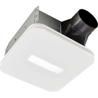
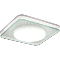
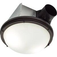
Decorative Fan-Light
INSTALLATION, USE AND MAINTENANCE INSTRUCTIONS
English - See page 2
Register this product at broan.com, broan.ca, nutone.com or nutone.ca. For Warranty Statement, or to order Service Parts: go to the appropriate website and type the model number in the "Model Search" field.
Register this product at broan.com, broan.ca, nutone.com or nutone.ca. For Warranty Statement, or to order Service Parts: go to the appropriate website and type the model number in the "Model Search" field.
Installer: Leave this manual with the homeowner. READ AND SAVE THESE INSTRUCTIONS
To reduce the risk of fire, electric shock, or injury to persons, observe the following:


To reduce the risk of fire, electric shock, or injury to persons, observe the following:
- Use this unit only in the manner intended by the manufacturer. If you have questions, contact the manufacturer at the address or telephone number listed in the warranty.
- Before servicing or cleaning the unit, switch the power off at the service panel and lock the service disconnecting means to prevent power from being switched on accidentally. When the service disconnecting means cannot be locked, securely fasten a prominent warning device, such as a tag, to the service panel.
- Installation work and electrical wiring must be done by a qualified person(s) in accordance with all applicable codes and standards, including fire-rated construction codes and standards.
- Sufficient air is needed for proper combustion and exhausting of gases through the flue (chimney) of fuel burning equipment to prevent backdrafting. Follow the heating equipment manufacturer's guideline and safety standards such as those published by the National Fire Protection Association (NFPA), and the American Society for Heating, Refrigeration and Air Conditioning Engineers (ASHRAE), and the local code authorities.
- When cutting or drilling into wall or ceiling, do not damage electrical wiring and other hidden utilities.
- Ducted fans must always be vented to the outdoors. • This unit must be grounded.
CAUTION

- For general ventilating use only. Do not use to exhaust hazardous or explosive materials and vapors.
- For installation in flat ceilings only.
- To avoid motor bearing damage and noisy and/or unbalanced impellers, keep drywall spray, construction dust, etc. off power unit.
- Please read specification label on product for further information and requirements.
CLEANING & MAINTENANCE
For quiet and efficient operation, long life, and attractive appearance - remove grille and vacuum interior of unit with the dusting brush attachment.
The motor is permanently lubricated and never needs oiling. If the motor bearings are making excessive or unusual noises, replace the blower assembly (includes motor and impeller).
OPERATION
Use an on/off switch or speed control to operate this ventilator. See "Wiring Diagram" for details.
ALL INSTALLATIONS
Start here.
IMPORTANT - The ducting from this fan to the outside of the building has a strong effect on the air flow, noise and energy use of the fan. Use the shortest, straightest duct routing possible for best performance, and avoid installing the fan with smaller ducts than recommended. Insulation around the ducts can reduce energy loss and inhibit mold growth. Fans installed with existing ducts may not achieve their rated airflow.

OPTION - To mount housing anywhere between ceiling framing: Use optional Hanger Bar Kit (sold separately from local distributors or website). Follow mounting instructions included with kit.
1. Remove blower and all packing material from fan housing.
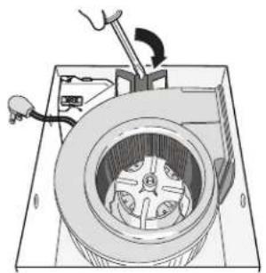

2. Remove wiring panel from fan housing (if already installed).

3. A pair of flanges may be attached to housing if desired or required.
Snap both flange pieces under rolled-over edge of housing (all four sides).
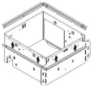
4. Attach grille brackets* to housing.


* Grille brackets are located in Styrofoam packing material in box.
NEW CONSTRUCTION
For Retrofit Installation - Skip to Page 5.
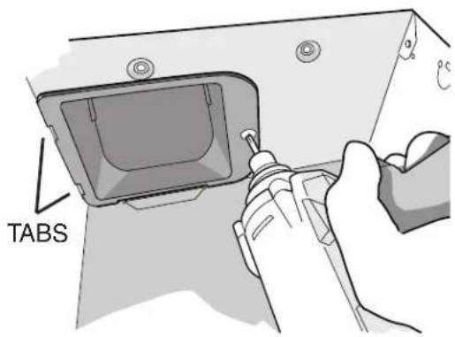
5. Attach damper/duct connector to fan housing.
Push connector through opening from inside of housing. Engage tabs and secure with screw from parts bag.
6. Mount housing to ceiling structure.
Make sure bottom of housing will be flush with finished ceiling.
For proper location when using 1/2" ceiling material: Bend out housing tabs to fit against bottom of structure.
Secure housing through mounting ears with appropriate fasteners (not included).
If mounting housing to I-joist, use wood blocking as shown.


7. Connect 4-in. round duct.

8. Connect wiring.
Connect power cable to housing with appropriate UL approved connector (not included). Make wiring connections as shown in "Wiring Diagram" section. Re-install wiring panel and secure with screw from parts bag.

9. Install blower.
Re-install blower. Secure blower with (2) screws from parts bag and plug blower into black receptacle.

10. Finish ceiling, then install grille.
Attach MOUNTING PLATE to housing with (2) SCREWS, using the GRILLE BACKETS installed in step 4.
Connect LIGHT PANEL PLUG to receptacle in corner of housing.
Place LIGHT PANEL SLOT over HOOK on MOUNTING PLATE.
Swing opposite side of LIGHT PANEL up to MOUNTING PLATE and secure with ATTACHMENT SCREW.
Line up GRILLE FRAME with (3) LIGHT PANEL OPENINGS and rotate GRILLE FRAME clockwise to secure it to LIGHT PANEL.

RETROFIT
5. Remove old fan.
Enlarge ceiling opening (if necessary) to 9 3/4" (parallel to joist) by 10 1/2" (perpendicular to joist). Leave ductwork and wiring in place.
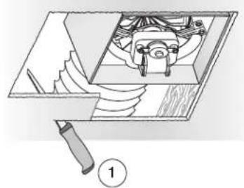
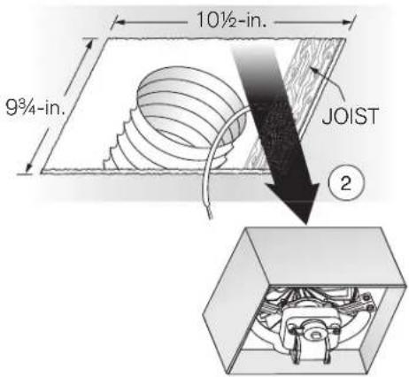
6. Fold mounting ears flat against housing.
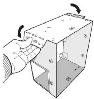
7. Connect wiring.
Connect power cable to housing with appropriate UL approved connector (not included). Make wiring connections as shown in "Wiring Diagram" section. Re-install wiring panel and secure with screw from parts bag.

8. Mount fan to ceiling structure.
Mount housing to ceiling structure with standard drywall or wood screws (not included) in locations shown.
*Center hole optional.

9. Connect 4-in. round duct.
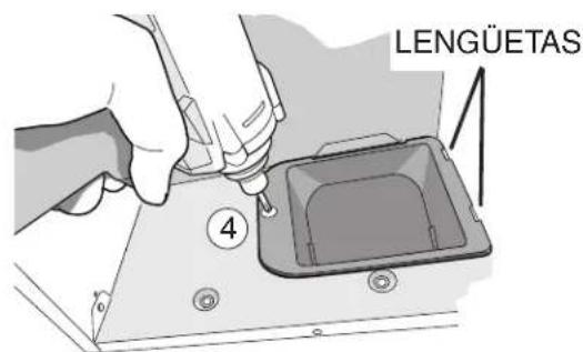
① Pull existing ducting through housing discharge opening. ② Attach and tape ducting to duct connector. ③ Push connector/ducting back through opening. ④ Engage tabs and secure with screw from parts bag.


Install blower. Finish ceiling, then install grille.
See Steps 9 & 10 on Page 5.
WIRING DIAGRAM




- DECORATIVE FAN-LIGHT
- INSTALLER: LEAVE THIS MANUAL WITH THE HOMEOWNER. READ AND SAVE THESE INSTRUCTIONS
- TO REDUCE THE RISK OF FIRE, ELECTRIC SHOCK, OR INJURY TO PERSONS, OBSERVE THE FOLLOWING
- CAUTION
- CLEANING & MAINTENANCE
- OPERATION
- ALL INSTALLATIONS
- REMOVE BLOWER AND ALL PACKING MATERIAL FROM FAN HOUSING
- REMOVE WIRING PANEL FROM FAN HOUSING (IF ALREADY INSTALLED)
- A PAIR OF FLANGES MAY BE ATTACHED TO HOUSING IF DESIRED OR REQUIRED
- ATTACH GRILLE BRACKETS* TO HOUSING
- NEW CONSTRUCTION
- ATTACH DAMPER/DUCT CONNECTOR TO FAN HOUSING
- MOUNT HOUSING TO CEILING STRUCTURE
- CONNECT 4-IN. ROUND DUCT
- CONNECT WIRING
- INSTALL BLOWER
- FINISH CEILING, THEN INSTALL GRILLE
- RETROFIT
- REMOVE OLD FAN
- FOLD MOUNTING EARS FLAT AGAINST HOUSING
- MOUNT FAN TO CEILING STRUCTURE
Brand : NuTone
Model : Roomside AERN80LWH
Category : Fan