
KEYBOARD ASSEMBLY 88KEY - Numeric keypad KORG - Free user manual and instructions
Find the device manual for free KEYBOARD ASSEMBLY 88KEY KORG in PDF.
| Product type | Master keyboard controller for KORG KKS system |
| Number of keys | 88 keys with RH-3 weighted hammer action |
| Controllers | Joystick, capacitive ribbon, SW1/SW2 switches |
| Connections | TO MODULE jack, TO MODULE (2nd) jack for connection to one or two sound generator modules |
| Dimensions (W x D x H) | 1425 x 442 x 128 mm |
| Weight | 21.7 kg (with attachment and covers) |
| Included accessories | Connection cable, attachment, finishing covers, retaining bar, screws |
| Compatible system | KORG KKS (KORG Component System) |
| Intended use | Control of KORG sound generator modules (e.g., M3-M) for music creation |
| Maintenance and cleaning | Clean with a dry, clean cloth. Do not use solvents or flammable products. |
| Safety | Avoid liquids, metal objects, impacts, and extreme temperatures. Disconnect before handling the connection cable. |
| Transport | Secure the module with the locking device or hook before transport to avoid sudden movements. |
| Repairability | Removable and interchangeable module. Fixing parts available (screws, bracket, support). Contact an authorized service center. |
| Power supply | Power is built into the sound generator module (not supplied with the keyboard alone). |
Frequently Asked Questions - KEYBOARD ASSEMBLY 88KEY KORG
User questions about KEYBOARD ASSEMBLY 88KEY KORG
0 question about this device. Answer the ones you know or ask your own.
Ask a new question about this device
Download the instructions for your Numeric keypad in PDF format for free! Find your manual KEYBOARD ASSEMBLY 88KEY - KORG and take your electronic device back in hand. On this page are published all the documents necessary for the use of your device. KEYBOARD ASSEMBLY 88KEY by KORG.
USER MANUAL KEYBOARD ASSEMBLY 88KEY KORG
Using the unit in the following locations can result in a malfunction.
- In direct sunlight
- Locations of extreme temperature or humidity
- Excessively dusty or dirty locations
- Locations of excessive vibration
- Close to magnetic fields
Interference with other electrical devices
Radios and televisions placed nearby may experience reception interference. Operate this unit at a suitable distance from radios and televisions.
Handling
To avoid breakage, do not apply excessive force to the switches or controls.
Care
If the exterior becomes dirty, wipe it with a clean, dry cloth. Do not use liquid cleaners such as benzene or thinner, or cleaning compounds or flammable polishes.
Keep this manual
After reading this manual, please keep it for later reference.
Keeping foreign matter out of your equipment
Never set any container with liquid in it near this equipment. If liquid gets into the equipment, it could cause a breakdown, fire, or electrical shock. Be careful not to let metal objects get into the equipment.
THE FCC REGULATION WARNING (for USA)
This equipment has been tested and found to comply with the limits for a Class B digital device, pursuant to Part 15 of the FCC Rules. These limits are designed to provide reasonable protection against harmful interference in a residential installation. This equipment generates, uses, and can radiate radio frequency energy and, if not installed and used in accordance with the instructions, may cause harmful interference to radio communications. However, there is no guarantee that interference will not occur in a particular installation. If this equipment does cause harmful interference to radio or television reception, which can be determined by turning the equipment off and on, the user is encouraged to try to correct the interference by one or more of the following measures:
- Reorient or relocate the receiving antenna.
- Increase the separation between the equipment and receiver.
- Connect the equipment into an outlet on a circuit different from that to which the receiver is connected.
- Consult the dealer or an experienced radio/TV technician for help.
Unauthorized changes or modification to this system can void the user's authority to operate this equipment.
Notice regarding disposal (for EU)

If this "crossed-out wheeled bin" symbol is shown on the product or in the operating manual, you must dispose of the product in an appropriate way. Do not dispose of this product along with your household trash. By disposing of this product correctly, you can avoid environmental harm or health risk. The correct method of disposal will depend on your locality, so please contact the appropriate local authorities for details.
KKS (KORG Component System)
This instrument is part of the KORG Komponent System. This versatile system keeps all of the sound generating circuitry, all of the external connectors and even the power supply together inside of the sound module (subsequently referred to as the modse). In this way, the instrument may be played with the module section tilted up or lying flat. In addition, the module section may be completely removed and operated as an independent tone module, or used with other KKS products for further convenience.
Parts and their functions
Keyboard Assembly
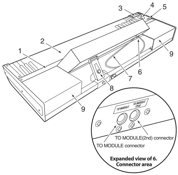
1. Retaining bar
This part keeps the sound module and the cover panels attached to the keyboard assembly. Four screws (M3 x 8) with it locks.
2. Keyboard
73-key: semi-weighted
88-key: RH-3 (Real Weighted Hammer Action 3)
3. Ribbon controller
By touching or rubbing your finger on this ribbon you can control various program and effect parameters on the connected module.
4. Joystick
By moving the joystick up/down/left/right you can control various program and effect parameters on the connected module.
5. SW1/SW2
You can use these switches to control various program or effect parameters on the connected module, or to turn the joystick or ribbon controller's Lock function on/off.
6. TO MODULE connector/TO MODULE(2nd) connector
One end of the connecting cable (8) will plug into this jack, and the other end will plug into the module's TO KYBD port. When connected, you'll be able to use the keyboard assembly's keyboard, joystick, ribbon controller and switches to control the module. If you're using only one module, connect it to the TO MODULE connector.

Certain modules may not support all of the controllers found on the keyboard assembly.
7. Connecting cable
This cable connects the keyboard assembly to the module.
8. Locking support
This part fastens the module to the keyboard assembly. The support arm allows the rear of the module to be raised, providing easy access to the panel controls, or lowered to lie flat. In addition, the entire locking support can be moved to any location along the rear rail, allowing the module to be freely positioned.
9. Cover panels
When using a single module, these covers can be attached to the keyboard assembly to provide a more finished look.
Locking support
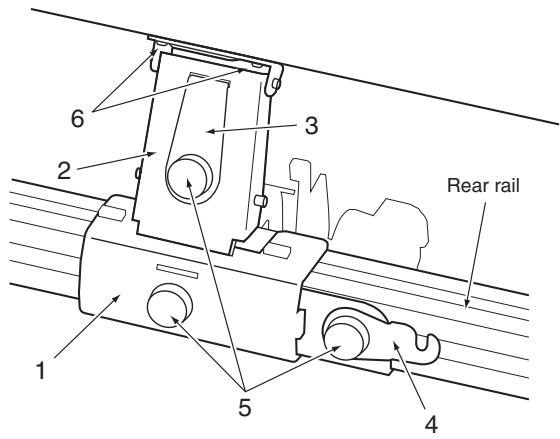
1. Bracket
This part is attached to the rear rail of the keyboard assembly. It can be moved horizontally so that you can re-position the module.
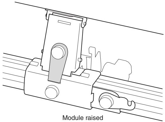
2. Support arm
This part supports the module when it's in the raised position.
3. Lock plate
This secures the arm when you're using the module in the raised position.
4. Latch
This secures the module when it's in the lowered/stored position, lying flat on the keyboard assembly.
5. Screws A
These fasten their respective parts.
6. Screws B
These are two screws (M4 x 6) that attach the support arm to the module.
Caution when adjusting the module
Please observe the following cautions in order to ensure safe and correct assembly and disassembly.

Please observe the following cautions in order to ensure safe and correct use, assembly and disassembly.

Be careful not to pinch your hands or fingers while raising or lowering the module.

Be sure that the module is powered-off when you connect or disconnect the cable between the keyboard assembly and the module. If you connect or disconnect this cable while the power is on, the module may stop operating correctly.

Before you proceed, be sure to read and follow the "Safety precautions" found earlier in this manual.
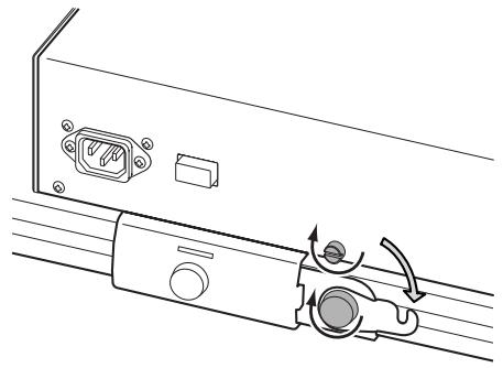
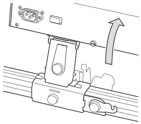
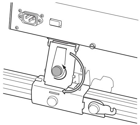
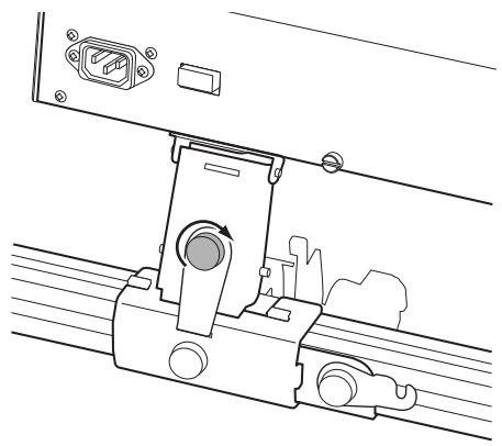
Raising the module
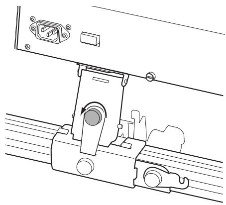
- Loosen both of the latch screws; the one securing the latch to the module, and the one connected to the bracket.
- Rotate the latch to the side as shown in the illustration, and tighten the screw A to fasten it in place. Also tighten the screw on the module so that it does not fall out.
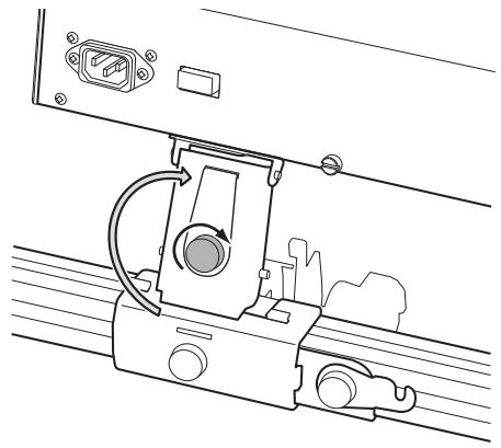
- Using the handle located on the rear panel, lift the module until it stops; and release the handle.
- Loosen the screw A that holds the lock plate, turn the lock plate 180 degrees as shown, and fit it into the slot in the bracket.
- Tighten the lock plate screw A to secure it in place.
This step is very important. If you move the keyboard assembly or apply excessive force to the module without fastening the lock plate to the bracket, the module may fall down resulting in damage or injury. For safety, fit the lock plate into the bracket and fasten it with the screw A.
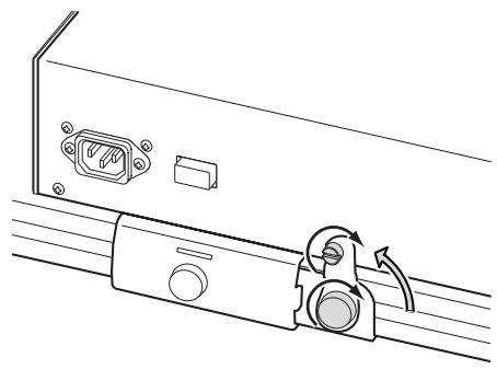
Lowering the module
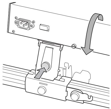
- Loosen the screw A securing the lock plate.
- Rotate the lock plate 180 degrees, fit it into the slot of the support arm, and tighten the screw to fasten it.
- As shown in the illustration, lightly press in on the screw A securing the lock plate to the arm, then gently lift the module using the handle located on the rear panel and release it. The module will slowly pivot down.
Be careful not to pinch your hand between the module and the keyboard assembly.
- Loosen the screw on the module and the screw A that secures the latch.
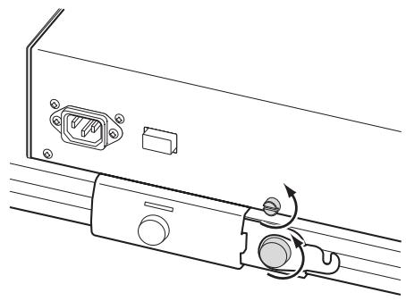
- As shown in the illustration, rotate the latch to the vertical position and slide it under the screw on the module. Then tighten both screws.
Module removal
- If the module is lying flat in the storage position, raise it as described in steps 1-5 of “Raising the module.”
- Disconnect the cable plug (L-shaped plug) connected to the TO KYBD connector located on the bottom of the module.
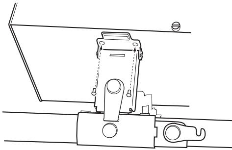
- As shown in the illustration, use your Phillips (+) screwdriver to remove the two screws B that attach the support arm to the module.
2 Be careful not to lose the screws you remove.
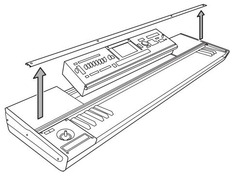
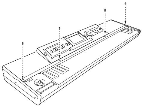
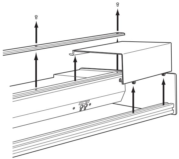
- Use your Phillips (+) screwdriver to remove the four screws that hold the retaining bar to the keyboard assembly.
Be careful not to lose the screws you remove.
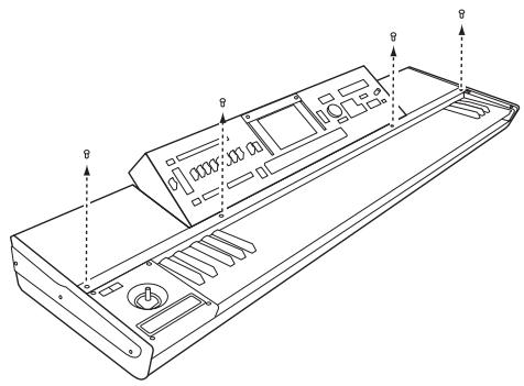
- Remove the retaining bar, and then lift the module using both hands and remove it from the keyboard assembly.
Be careful not to pinch your hand between the module and keyboard assembly.
Module installation
- Make sure that the support arm is folded down. Hold the module in both hands and carefully place it on the keyboard assembly.
Be careful not to pinch your hand between the module and keyboard assembly.
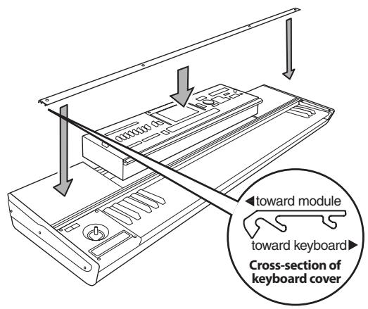
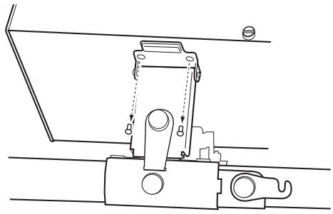
- Orient the retaining bar correctly as shown in the illustration, and place it on top of the module.
Align the screw holes in the retaining bar with the screw holes in the keyboard assembly, and finger-tighten the four screws. Finally, use your Phillips (+) screwdriver to firmly tighten the four screws.
Don't attempt to forcibly tighten the screws if the screw holes are not aligned. Doing so may cause damage to the unit.
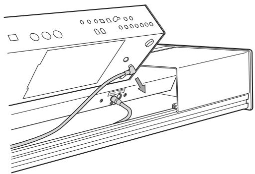
- Using the handle located on the rear panel, lift the module up, align the screw holes in the module with the screw holes in the support arm, and use your Phillips (+) screwdriver to install the two screws B that you removed when detaching the module.
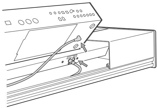
- Connect the included cable.
Connect the L-shaped plug of the cable to the TO KYBD connector on the module, and connect the straight plug to the TO MODULE connector on the keyboard assembly. If the TO MODULE connector is already being used to connect another module, then use the TO MODULE (2nd) connector.
The included cable is only for connecting the TO KYBD connector to the TO MODULE or TO MODULE (2nd) connector. Do not connect it to any other connector.
If you're using only one module, connect it to the TO MODULE connector.
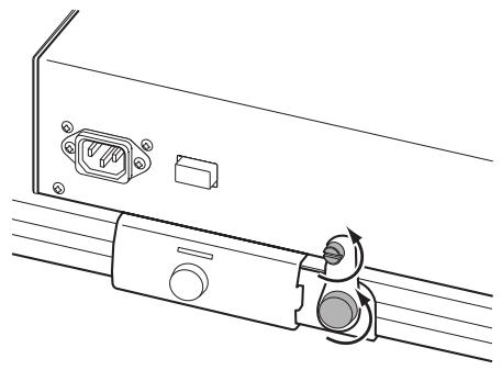
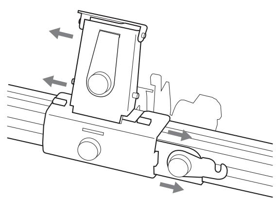
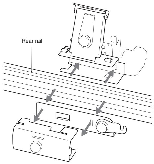
Locking support assembly
As shown in the illustration, the support arm, bracket and latch parts fit together around the rear rail to form the locking support assembly. The raised tabs on the support arm slide into the slots on the top of the bracket to hold everything together. To attach the locking support assembly, fasten the bracket to the support arm by sliding it horizontally (to the left) and tightening the screw on the bracket. To remove the locking support assembly, loosen the screw and slide the bracket to the right to release the two pieces.
Make sure that the bracket is oriented correctly.
When performing this step, be careful not to cut your hand on the metal parts.
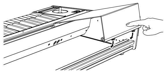
Cover panels
The keyboard assembly can be used with or without the these decorative "filler" panels. The cover panels will need to be removed when using two modules. As shown in the illustration, the front edge of the cover panels are held in place by the retaining bar. The back edge of the cover panels fit into the channel on the top of the keyboard assembly's rear rail. To remove the cover panels, remove the retaining bar as shown in step 4 of "Module removal" and lift off the cover panels. Replace the retaining bar as described in step 2 of "Module installation." To replace the cover panels, remove the retaining bar, place the back edge of the cover panels on the top of the rear rail, and replace the retaining bar.
Caution when attaching the cover panel
Align the projections of the cover panel with the slot of the rear rail, and press the cover panel into place.
If you press the cover panel when the projections are not aligned with the slot, you may damage the projections.
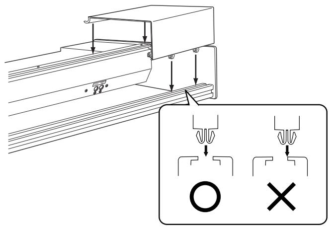
If the cover panel comes open as shown below after you've attached it, apply gentle pressure to the rear side and fit the projections of the cover panel into the slot of the rear rail.
Moving precautions
If you transport the keyboard assembly with the module in the raised position, the lock plate must be fitted into the slot on the bracket and secured in place by tightening the lockplate screw. If you transport the keyboard assembly with the module in the lowered (storage) position, the latch must be connected to the module, with both the module and bracket screws securely fastened.
If you transport the system without fastening these screws, the module may move abruptly, causing damage or injury.
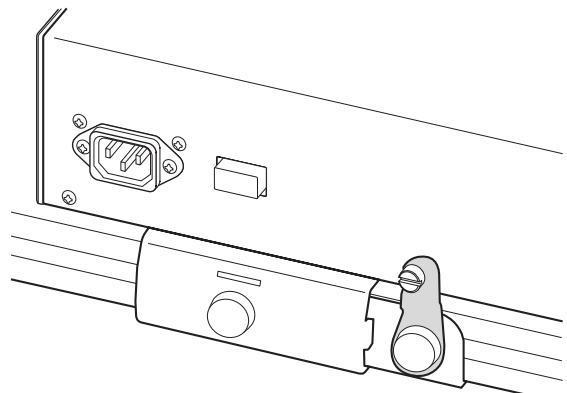
Module lowered (storage position)
Caution when using multiple modules
- When using more than one module, be sure both modules are turned off before connecting or disconnecting either of the cables connected to the TO MODULE and TO MODULE (2nd) connectors.
- When using more than one module, the module connected to the TO MODULE connector must be turned on in order for the module connected to the TO MODULE (2nd) connector to be detected by the keyboard assembly and to function properly.
- The lit/dark status of SW1/SW2 will reflect the state of the module connected to the TO MODULE connector. The SW1/SW2 lit/dark status of the module connected to the TO MODULE (2nd) connector will not be reflected. Be aware that the state of the TO MODULE (2nd) unit may not necessarily match the SW1/SW2 status. If you want the lit/dark indication to match the state of the TO MODULE (2nd) unit, you would need to set the On/Off and Toggle/Momentary setting of each Program, Combination, or Song of the module connected to the TO MODULE (2nd) connector to be identical to the settings of the module connected to the TO MODULE connector.
The Global mode menu command "After Touch Calibration" cannot be selected from an M3-M connected to the TO MODULE (2nd) connector. In order to execute this command, the M3-M must be connected to the TO MODULE connector.
Specifications
Keyboard 73-key: semi-weighted
88-key: RH-3 (Real Weighted Hammer Action 3)
Controllers Joystick
Ribbon controller SW1/SW2
Control connector
TO MODULE connector TO MODULE(2nd) connector
Dimensions (W× D× H)
73-key: 1189 × 371 × 128 ~mm 46.8 × 14.6 × 5.0 inches
88-key: 1425 × 442 × 128 ~mm 56.1 × 17.4 × 5.0 inches
Weight 73-key: 12.5kg / 27.6 lbs.
(including cover panels and locking support)
88-key: 21.7kg / 47.8 lbs.
(including cover panels and locking support)
Included items
Connection cable x 1
- Appearance and specifications of this product are subject to change without notice.
Précautions
Emplacement
3. Ribbon Controller
This product has been manufactured according to strict specifications and voltage requirements that are applicable in the country in which it is intended that this product should be used. If you have purchased this product via the internet, through mail order, and/or via a telephone sale, you must verify that this product is intended to be used in the country in which you reside.
WARNING: Use of this product in any country other than that for which it is intended could be dangerous and could invalidate the manufacturer's or distributor's warranty.
Please also retain your receipt as proof of purchase otherwise your product may be disqualified from the manufacturer's or distributor's warranty.
REMARQUE IMPORTANTE POUR LES CLIENTS
- Interference with other electrical devices
- Handling
- Care
- Keep this manual
- Keeping foreign matter out of your equipment
- THE FCC REGULATION WARNING (for USA)
- Notice regarding disposal (for EU)
- KKS (KORG Component System)
- Parts and their functions
- Keyboard Assembly
- Retaining bar
- Keyboard
- Ribbon controller
- Joystick
- SW1/SW2
- TO MODULE connector/TO MODULE(2nd) connector
- Connecting cable
- Locking support
- Cover panels
- Locking support
- Bracket
- Support arm
- Lock plate
- Latch
- Screws A
- Screws B
- Caution when adjusting the module
- Raising the module
- Lowering the module
- Module removal
- Module installation
- Locking support assembly
- Cover panels
- Caution when attaching the cover panel
- Moving precautions
- Caution when using multiple modules
- Specifications
- Précautions
- Emplacement
- REMARQUE IMPORTANTE POUR LES CLIENTS
Brand : KORG
Model : KEYBOARD ASSEMBLY 88KEY
Category : Numeric keypad