
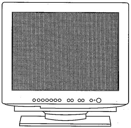
CM815ET PLUS - Computer monitor HITACHI - Free user manual and instructions
Find the device manual for free CM815ET PLUS HITACHI in PDF.

| Product type | CRT computer monitor |
| Brand | HITACHI |
| Model | CM815ET PLUS |
| Screen size | 15 inches (diagonal) |
| Technology | CRT (cathode ray tube) |
| Maximum resolution | 1024 x 768 pixels |
| Refresh rate | 60 Hz (typical) |
| Connectivity | VGA (D-Sub 15-pin) |
| Dimensions (W x H x D) | 360 x 370 x 380 mm (approx.) |
| Weight | 13 kg (approx.) |
| Power supply | 100-240 V, 50/60 Hz |
| Power consumption | 75 W (max) |
| Main functions | Image display, contrast and brightness adjustments, degaussing |
| Maintenance and cleaning | Clean with a soft, dry cloth; avoid chemical products |
| Safety | Do not open the case; unplug before cleaning; risk of electric shock |
| Spare parts | Power cable, VGA cable (available on the market) |
| Repairability | Repair by a qualified technician; parts available from the manufacturer |
| General information | Manual in PDF; after-sales service: france.consumateur@hitachi-eu.com |
Frequently Asked Questions - CM815ET PLUS HITACHI
User questions about CM815ET PLUS HITACHI
0 question about this device. Answer the ones you know or ask your own.
Ask a new question about this device
Download the instructions for your Computer monitor in PDF format for free! Find your manual CM815ET PLUS - HITACHI and take your electronic device back in hand. On this page are published all the documents necessary for the use of your device. CM815ET PLUS by HITACHI.
USER MANUAL CM815ET PLUS HITACHI
EasyMenu is the On Screen Display function for easy operation.
READ THE INSTRUCTIONS INSIDE CAREFULLY. KEEP THIS USER MANUAL FOR FUTURE REFERENCE.
For future reference, record the serial number of your color monitor.
SERIAL No.
The serial number is located on the rear of the monitor.
This monitor is ENERGY STAR® compliant when used with a computer equipped with VESA DPMS.
The ENERGY STAR® emblem does not represent EPA endorsement of any product or service.


NOTE:
The information in this manual is subject to change without notice. The manufacturer assumes no responsibility for any errors that may appear in this manual.
TRADEMARK ACKNOWLEDGEMENT
VGA is a registered trademark of International Business Machines Corporation.
VESA is a trademark of a nonprofit organization, Video Electronics Standard Association.
ENERGY STAR® is a U.S. registered mark of Environmental Protection Agency (EPA).
REMARQUE:
The following features are provided by the Colour Monitor.
Sharpest Focus and Highest Contrast
Flat screen CRT with anti-glare, dynamic focus circuit, dark glass, and an INVAR shadow mask gives the sharpest focus and highest contrast to minimize eye fatigue.
Wide-range Multi-Scanning
Automatic scanning and automatic adjustment to conform with a wide range of scanning frequencies and user requirements.
Digital Picture Control Function
Position, size, rotation, pincushion, trapezoid, right pincushion and right trapezoid are adjustable by digital controls.
Geometry setting can be stored for different H/V frequencies. Microprocessor-based preset functions can store 26 sets of geometry settings including the standard factory settings.
Digital Colour Control Function
Red, green, and blue colour balance is adjustable by digital control.
An adjusted colour setting can be stored and recalled by the colour select button.
Power Saving System
The Environmental Protection Agency (EPA) has established a voluntary program by which manufacturers enable computer products to go into low power states while not being used. This monitor has a low power "sleep" mode, which is compliant with the EPA requirements for the ENERGY STAR® program, and will assist you in conserving energy.
Please refer to the section of "POWER SAVING SYSTEM" for details.
EasyMenu
An On Screen Display function that allows direct access to adjust all operations from the front switches.
Moire Reduction
This monitor has horizontal and vertical moirre reduction function.
PLUG & PLAY
This monitor is VESA DDC1/2B compliant when used with a computer compliant with VESA DDC (Display Data Channel).

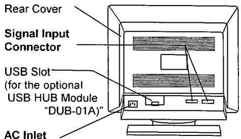
NEVER REMOVE THE REAR COVER!
The rear cover MUST be removed only by authorized service personnel. This colour monitor contains high voltage components.
THE RECEPTACLE SHOULD BE CLOSE TO THE MONITOR AND EASILY ACCESSIBLE!
■ INSTALL THE UNIT IN AN SUITABLE ENVIRONMENT !
DO NOT expose this monitor to rain or moisture to prevent electric shock or fire hazard. This unit is designed to be used in an office or business environment.
DO NOT subject the unit to vibrations, dust, or corrosive gases.
■ KEEP IN A WELL VENTILATED PLACE!
DO NOT cover this monitor or place anything against any sides (not only the top, right and left side but also the rear and bottom side) of unit. Ventilation holes are provided at all sides of the rear cover to prevent the temperature from rising.
- KEEP AWAY FROM HEAT SOURCES!
AVOID placing the unit in direct sunshine or near a heating appliance.
BE CAREFUL OF MAGNETIC FIELDS!
DO NOT place a magnet, loudspeaker system, floppy disk drive, printer, or anything which will generate magnetism near the unit. A magnetic field may cause blurred colours or distortion of the displayed pattern.
BE CAREFUL OF GENERATED MAGNETISM!
After the power has been turned on or "DEGAUSS" button has been pressed, the CRT is demagnetized for approximately 10 seconds. This generates a strong magnetic field around the front cover which may affect the data stored on magnetic tape or disks near the front cover. Place such magnetic recording equipment and tapes/disks away from this unit.
Avoid direct rays of the sun or room lighting onto the CRT screen in order to prevent eye fatigue.
THE ENCLOSED POWER CORD MUST BE USED!
In Europe, a proper European standard approved power cord is to be used with this monitor. For a rated current up to 6 A, a type not lighter than H05VV-F 3G 0.75 mm² or H05VVH2-F 3G 0.75 mm² must be used.
In USA/Canada, use a UL LISTED/CSA LABELLED or CERTIFIED power cord set meeting the following specifications
Rating: min. 125V, 7A
Length: max. 3.0m
Type: SVT or SJT
Plug type: NEMA 5-15P figure, Parallel blade, Grounding type
Failure to do so may cause fire or electric shock hazard.
USE ONLY THE CORRECT VOLTAGE POWER OUTLET WITH SAFETY GROUND CONNECTION!
100 - 120 V for USA, Canada, etc.
200 - 240 V for Europe, etc.
(This monitor will automatically adjust to the input voltage 100 - 120 / 200 - 240V.)
CAUTION for 200 - 240V operation only
This equipment relies on the protective devices in the building installation for short-circuit and overcurrent protection. Refer to the following table for the suitable number and location of the protective devices which should be provided in the building installation.
Informative examples of protective devices in single - phase equipment or sub - assemblies
| Protection against | Minimum number of fuses or circuit - breaker poles | Location | |
| Case A: Equipment to be connected to POWER SYSTEMS with earthed neutral reliably identified, except for Case C below. | Earth faults | 1 | Phase conductor |
| Overcurrent | 1 | Either of the two conductors | |
| Case B: Equipment to be connected to any supply, including IT POWER SYSTEMS and supplies with reversible plugs, except for Case C below. | Earth faults | 2 | Both conductors |
| Overcurrent | 1 | Either of the two conductors | |
| Case C: Equipment to be connected to 3-wire power systems with earthed neutral reliably identified. | Earth faults | 2 | Each phase conductor |
| Overcurrent | 2 | Each phase conductor |
Verify that the protective devices in the building installation meet the conditions in the table prior to installing the equipment.
■ BE CAREFUL OF POWER CORD CONNECTION!
Before inserting the plug of the power cord into a receptacle of the correct voltage, check that the connection portion of the power cord is clean (with no dust). Then, insert the plug of power cord to a receptacle firmly, otherwise it may cause electrical shock or fire.
■ REMOVE THE POWER CORD FOR COMPLETE SEPARATION !
For complete separation from the power source, remove the power cord from the monitor or from the wall outlet.
AVOID FREQUENT POWER ON-OFF SWITCHING!
DO NOT repeat OFF and ON in a short period. It may cause blurred colours or distortion of the displayed pattern.
■ BE CAREFUL OF STATIC ELECTRICITY ON CRT SURFACE!
To prevent electrical shock by the static electricity on the CRT surface, disconnect the power cord at least 30 SECONDS AFTER turning off the power.
ABOUT CLEANING
This monitor has a non-glare and anti-electrostatic treatment on the surface of the screen. Use water or alcoholic solvent with soft cloth like gauze to clean the surface of the screen.
NEVER use abrasive, glass cleaner containing highly concentrated ammonia and strong base chemicals since they damage the surface treatment.
Clean the cabinet and controls with a lightly moistened soft cloth.
DO NOT use aerosol sprays, solvents or abrasive cleaners.
FCC (Federal Communications Commission) STATEMENT WARNING
WARNING : This equipment has been tested and found to comply with the limits for a Class B digital device, pursuant to Part 15 of the FCC Rules. These limits are designed to provide reasonable protection against harmful interference in a residential installation. This equipment generates, uses, and can radiate radio frequency energy and, if not installed and used in accordance with the instructions, may cause harmful interference to radio communications. However, there is no guarantee that interference will not occur in a particular installation. If this equipment does cause harmful interference to radio or television reception, which can be determined by turning the equipment off and on, the user is encouraged to try to correct the interference by one or more of the following measures:
Reorient or relocate the receiving antenna.
- Increase the separation between the equipment and receiver.
- Connect the equipment into an outlet on a circuit different from that to which the receiver is connected.
Consult the dealer or an experienced radio / TV technician for help
Instructions to Users : This equipment complies with the requirements of FCC (Federal Communication Commission) equipments provided that following conditions are met.
(1) Power cord : Unshielded power cord must be used.
(2) Video inputs : The input signal amplitude must not exceed the specified level.
CAUTION : Changes or modifications not expressly approved by the party responsible for compliance could void the user's authority to operate the equipment.
Declaration of Conformity
According to 47CFR, Part 2 and 15 for
Class B Personal Computers and
Peripherals; and / or
CPU Boards and Power Supplies used
with Class B Personal Computers:
We: Nissci Sangyo America, Ltd.
Located at: 200 Lowder Brook Drive Suite 2200, Westwood, MA 02090-1124 USA
Declare under sole responsibility that the product identified herein, complies with 47CFR Part 2 and 15 of the FCC rules as a Class B digital device. Each product marketed, is identical to the representative unit tested and found to be compliant with the standards. Records maintained continue to reflect the equipment being produced can be expected to be within the variation accepted, due to quantity production and testing on a statistical basis as required by 47CFR § 2.909. Operation is subject to the following two conditions: (1) This device may not cause harmful interference, and (2) This device must accept any interference received, including interference that may cause undesired operation. The above named party is responsible for ensuring that the equipment complies with the standards of 47CFR § 15.101 to 15.109.
Trade name: Color Monitor, USB HUB Module
Model Number: CM811/CM813/CM815 + DUB 01
Signature of Party Responsible: Printed name of Party Responsible:
Executed on (Date), at (Place):
August 10. 1999. MA. USA
FOR THE CUSTOMERS IN CANADA for models
NOTICE: This Class B digital apparatus complies with ICES-003.
FOR THE CUSTOMERS IN THE U.K.
THIS PRODUCT IS SUPPLIED WITH A TWO PIN MAINS PLUG FOR USE IN MAINLAND EUROPE. FOR THE U.K. PLEASE REFER TO THE NOTES ON THIS PAGE.
IMPORTANT FOR UNITED KINGDOM
WORDING FOR CLASS I EQUIPMENT INSTRUCTION BOOKS AND LABELS
The mains lead on this equipment is supplied with a moulded plug incorporating a fuse, the value of which is indicated on the pin face of the plug. Should the fuse need to be replaced, an ASTA or BSI approved BS 1362 fuse must be used of the same rating. If the fuse cover is detachable never use the plug with the cover omitted. If a replacement fuse cover is required, ensure it is of the same colour as that visible on the pin face of the plug. Fuse covers are available from your dealer.
DO NOT cut off the mains plug from this equipment. If the plug fitted is not suitable for the power points in your home or the cable is too short to reach a power point, then obtain an appropriate safety approved extension lead or consult your dealer.
Should it be necessary to change the mains plugs, this must be carried out by a competent person, preferably a qualified electrician.
If there is no alternative to cutting off the mains plug, ensure that you dispose of it immediately, having first removed the fuse, to avoid a possible shock hazard by inadvertent connection to the mains supply.
WARNING: THIS EQUIPMENT MUST BE EARTHED
IMPORTANT
The wires in the mains lead are coloured in accordance with the following code:
Green and Yellow = Earth, Blue = Neutral, Brown = Live.
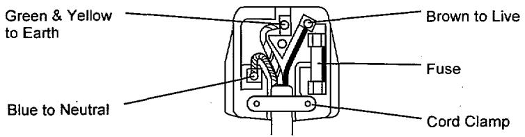
As these colours may not correspond with the coloured markings identifying the terminals in your plug, proceed as follows:
The wire which is coloured GREEN and YELLOW must be connected to the terminal in the plug which is marked with the letter E or by the earth symbol ② or coloured GREEN or GREEN and YELLOW.
The wire coloured BLUE must be connected to the terminal marked with the letter N or coloured BLUE or BLACK. The wire coloured BROWN must be connected to the terminal marked with the letter L or coloured BROWN or RED.
INSTALLATION
Install the monitor in the following way, taking care to maintain safety.
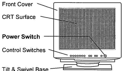
FRONT VIEW
REAR VIEW
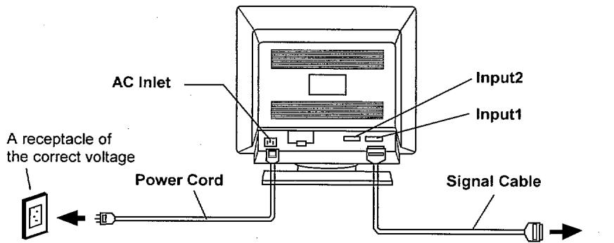
1. Installation
Install the monitor on a horizontal base.
2. Power Cord Connection
① Make sure of using the power cord meeting the safety standard of the country in which you are using the monitor.
② Insert the connector of a power cord to the AC Inlet of the monitor.
③ Insert the plug of the power cord to a receptacle of the correct voltage.
3. Signal Cable Connection
① Use video signal cable which is included in the carton box. (Cable model name:HD-0501FXL)
② Insert the connector of a signal cable to the Signal Input Connector Input 1 or Input 2 of the monitor, with attention to the suitability, and secure the screws on the connector shell firmly.
③ Connect the other connector end of the signal cable to the host computer.
to the host computer
- Use a signal cable with the D-Sub Mini 15-pin Connector.
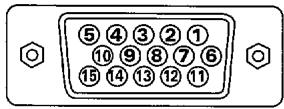
| Pin No. | Input 1 | Input 2 |
| 1 | Red Video | Red Video |
| 2 | Green Video (Sync. optional) | Green Video (Sync. optional) |
| 3 | Blue Video | Blue Video |
| 4 | No Pin | No Pin |
| 5 | No connection | No connection |
| 6 | Red Ground | Red Ground |
| 7 | Green Ground | Green Ground |
| 8 | Blue Ground | Blue Ground |
| 9 | No connection | No connection |
| 10 | Ground | Ground |
| 11 | No connection | No connection |
| 12 | Bi-directional Data [SDA] | No connection |
| 13 | H.Sync. (or H/V) | H.Sync. (or H/V) |
| 14 | V. Sync. [VCLK] | V. Sync. |
| 15 | Data Clock [SCL] | No connection |

- If the graphics board supplies more than one type of sync. signal, the sync. signal type will be automatically selected by the monitor, with the priority shown in the following table.
| Sync. Signal Type | Priority |
| H, V Separate Sync. | 1 |
| H / V Composite Sync. | 2 |
| Sync. on Green Video | 3 |
4. Power On
Turn on the Power Switch of the monitor first, then the computer.
Refer to Page 9 "POWER ON/OFF".
NOTICE :
After turning OFF the switch, wait at least 5 seconds to restart the monitor. Otherwise the monitor may operate unusually.
If the picture doesn't appear, turn OFF the power switch, make sure of the following and wait at least 30 seconds to restart the monitor.
Make sure the power switch of the computer, power cord connection, signal cable connection and the input sync. signal are right.
If the Colour is impure on the screen after turning ON the monitor, wait for about 10 minutes and press the Degauss button.
STANDARD SETTINGS
Microprocessor-based preset functions can store 26 sets of geometry settings including the standard settings. The following industrial standard settings have been pre-programmed by the factory.
| No. | Video Mode Name(with Resolution and Vertical Frequency) | Horizontal Frequency | Video Mode | CM811 | CM813 | CM815 | |||
| 1 | VGA | 640 × 400 | -70 Hz | 31.47 kHz | VGA | L | L | L | |
| 2 | VESA | 800 × 600 | -85 Hz | 53.67 kHz | VESA | L | L | L | |
| 3 | VESA | 1024 × 768 | -85 Hz | 68.68 kHz | VESA | L | L | L | |
| 4 | Mac | 1152 × 870 | -75 Hz | 68.68 kHz | Mac | L | |||
| 5 | VESA | 1280 × 1024 | -85 Hz | 91.15 kHz | VESA | L | L | L | |
| 6 | VESA | 1600 × 1200 | -85 Hz | 106.25 kHz | VESA | L | |||
| 7 | VESA | 1600 × 1200 | -90 Hz | 112.50 kHz | VESA | L | L | ||
| 8 | 1856 × 1392 | -72 Hz | 102.95 kHz | L | |||||
| 9 | VESA | 1856 × 1392 | -75 Hz | 112.50 kHz | VESA | L | |||
| 10 | 2048 × 1536 | -71 Hz | 113.64 kHz | L | |||||
NOTE:
Input signals with approximately the same frequencies may be regarded as the same signal.
The following horizontal timing conditions are recommended (at sync. H, V separate or H/V composite).
for 31 kHz - 55 kHz horizontal frequency: Horizontal front porch should be more than 0.1 μs. Horizontal sync. width should be within 1.0 - 3.8 μs. Horizontal back porch should be more than 1.2 μs. Horizontal blanking width should be more than 3.5 μs. for 55 kHz - 130 kHz horizontal frequency: Horizontal front porch should be more than 0.1 μs. Horizontal sync. width should be within 0.8 - 3.0 μs. Horizontal back porch should be more than 1.1 μs. Horizontal blanking width should be more than 2.3 μs.
The following vertical timing conditions are recommended. Vertical front porch should be more than 9 s Vertical sync. width should be less than 100~ s Vertical back porch should be more than 400~ s Vertical blanking width should be more than 450~ s
In case the front or back porch is extremely long, or the data display time is extremely short, it may not be able to set the expected size and position.
Standard settings are subject to change without notice.
This monitor is tested and conformed compliance with ZH1/618 and EN29241-3 (ISO9241-3) ergonomics requirement on the following video modes : "VESA 1024 × 768 - 85 Hz", "VESA 1280 × 1024 - 85 Hz", "VESA 1600 × 1200 - 85 Hz"
This monitor is tested and conformed compliance with FCC (and ICES-003) Class B requirement on the video mode "1600 × 1200 - 92kHz".
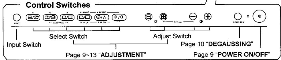
POWER ON/OFF
Press the Power switch, to switch the power ON or OFF.
When power is ON, the power LED lights.
INPUT
This monitor has two input terminals, INPUT 1 and INPUT 2. Therefore, you may connect two computers simultaneously. When two computers are active, you may switch the input signal by using the EasyMenu controls.
INPUT SELECT
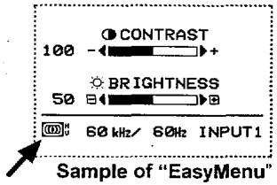
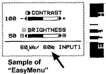
INPUT 1 is the initial factory default setting. If you would like to use INPUT 2, proceed to the "EasyMenu" and select the "INPUT SELECT" mode. Press the "+" key and this will select INPUT 2.
Plug and Play function is only supported on INPUT 1, and not supported on INPUT 2.
Sample of "EasyMenu"
AUTO INPUT SELECT
This monitor has an "INPUT AUTO SELECT" function which will select the input by scanning for an input signal on either INPUT 1 or INPUT 2.
"ON": Press the " " key.
■ When there is no input signal received from the input connection which was selected by "INPUT SELECT", the "INPUT AUTO SELECT" function will select the alternate connection. If there is no input signal received from either connection the monitor will default to the "POWER SAVE" mode.
If there are two computers connected to the monitor and for example you restart one of the computers or it is activated from the "POWER SAVE" mode, it is possible that the monitor may change to an undesired input connection. This may be easily correct by changing the input selection to the desired INPUT 1 or INPUT 2 using the "INPUT SELECT" function.
"OFF": Press the " " key.
■ When the "INPUT AUTO SELECT" function is placed in the "OFF" mode, the monitor will default back to the selection that has been selected by the "INPUT SELECT" function, and the input will no longer be selected automatically.
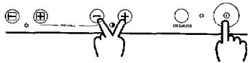
DEGAUSSING
Press the switch "DEGAUSS", to degauss manually.
Use this function only when you see colour impurities on the screen after turning ON the monitor. Remember, the monitor is automatically degaussed during initial power on.
Wait for about 10 minutes before repeating the function.
ADJUSTMENT
Press the select switch of the item you want to adjust. Then you can adjust by the adjust switches shown in following tables.
■ You can store the adjusted condition. Refer to Page 14 "STORE".
The On Screen Display function of "EasyMenu" shows selected items and adjusting conditions. You can select the EasyMenu Language. See the table below.

Select


Adjust
Sample of "EasyMenu"
| Item | Select Switch | Adjust Switch | Function | |
| Language Select | and simultaneously. | changes the language to the next mode. ENGLISH →DEUTSCH →ESPAÑOL →ITALIANO →FRANÇAIS | ||
| changes the language to the previous mode. FRANÇAIS →ITALIANO →ESPAÑOL →DEUTSCH →ENGLISH | ||||
| Contrast | makes Contrast brighter excluding background. | |||
| makes Contrast darker excluding background. | ||||
| Brightness | makes Brightness brighter including background | |||
| makes Brightness darker including background. | ||||
ADJUSTMENT (Continue)
| Item | Select Switch | Adjust Switch | Function | |||
| ※ | 0 | |||||
| H. Position | #/# | + | moves the position to the right. | |||
| - | moves the position to the left. | |||||
| H. Size | # | expands horizontally. | ||||
| # | shrinks horizontally. | |||||
| V. Position | #/# | + | moves the position up. | |||
| - | moves the position down. | |||||
| V. Size | # | expands vertically. | ||||
| # | shrinks vertically. | |||||
| Rotation | #/4 | # | rotates clockwise. | |||
| # | rotates counter clockwise. | |||||
| Pincushion | #/# | + | curves the left/right sides outwards. | |||
| - | curves the left/right sides inwards. | |||||
| Trapezoid | # | expands the top side, and shrinks the bottom side. | ||||
| # | shrinks the top side, and expands the bottom side. | |||||
| Right Pincushion | #/# | + | curves the right side outwards. | |||
| - | curves the right side inwards. | |||||
| Right Trapezoid | # | expands the right top side, and shrinks the right bottom side. | ||||
| # | shrinks the right top side, and expands the right bottom side. | |||||

ADJUSTMENT (Continue)
| Item | Select Switch | Adjust Switch | Function | |||
| ☐ | ☐ | |||||
| Colour Select | ☐/☐ | ☐ | changes the colour to the next mode.No.1:9300K → No.2:6500K→ No.3:5000K→ No.4:USER (if available) | |||
| ☐ | changes the colour to the previous mode.No.4:USER (if available)→ No.3:5000K → No.2:6500K→ No.1:9300K | |||||
| Colour Balance | Red | ☐/☐ and ♂/☐simultaneously.When Green or Blue is selected, ♂/☐is valid singly. | ☐ | makes the Red stronger. When the Red reaches the upper limit, it makes the Green and Blue weaker. | ||
| ☐ | makes the Green and Blue stronger.When the Green or Blue reaches the upper limit, it makes the Red weaker. | |||||
| Green | ☐/☐ and ♂/☐simultaneously.When Blue or Red is selected, ♂/☐is valid singly. | ☐ | makes the Green stronger. When the Green reaches the upper limit, it makes the Blue and Red weaker. | |||
| ☐ | makes the Blue and Red stronger.When the Blue or Red reaches the upper limit, it makes the Green weaker. | |||||
| Blue | ☐/☐ and ♂/☐simultaneously.When Green or Red is selected, ♂/☐is valid singly. | ☐ | makes the Blue stronger. When the Blue reaches the upper limit, it makes the Red and Green weaker. | |||
| ☐ | makes the Red and Green stronger.When the Red or Green reaches the upper limit, it makes the Blue weaker. | |||||
| Colour Reset | (This operation is valid only when Red, Green or Blue is selected already.) | ☐ | cancels the currently adjusted colour, and calls the colour condition of the previously selected colour mode. | |||
| simultaneously, for about 2 seconds. | ||||||
- When EasyMenu is not shown, you can start the adjustment of Contrast and Brightness only, without pressing any select switch.
It is recommended to follow the following procedures for the adjustment of distortions; (1) "Rotation"
(2) "Pincushion" and "Trapezoid" (Adjust the left side.)
(3) "Right Pincushion" and "Right Trapezoid" (Adjust the right side.)
The mode "No.4:USER" is not factory set, and it is programmable if desired. After adjustment of "Colour Balance" (Red, Green or Blue) and "STORE" (refer to page 14), your colour balance will be restored by selecting "No.4:USER".
ADJUSTMENT (Continue)
| Item | Select Switch | Adjust Switch | Function | ||
| ※ | ① | ||||
| H. Moire Reduction | □□ and */0 simultaneously. | ⊕ | operates the horizontal moiré changing circuit. | ||
| ⊕ | stops the horizontal moiré changing circuit. | ||||
| ⊕ | makes the operation of the horizontal moiré changing circuit stronger. | ||||
| ⊕ | makes the operation of the horizontal moiré changing circuit weaker. | ||||
| V. Moire Reduction | □□ and */0 simultaneously. | ⊕ | operates the vertical moiré changing circuit. | ||
| ⊕ | stops the vertical moiré changing circuit. | ||||
| ⊕ | makes the operation of the vertical moiré changing circuit stronger. | ||||
| ⊕ | makes the operation of the vertical moiré changing circuit weaker. | ||||
Moire may appear on the screen due to interference between CRT dot pitch and video signal by conditions of video image, display size, display brightness, etc. Adjust the conditions of display size, display brightness, etc., before the adjustment of moir.
In some cases, this function may cause deterioration of display quality, such as focus, jitter, etc.
The condition of the moiré changing circuit will be indicated by pressing any switch (Select Switch or Adjust Switch), as the following.
| Indicated symbol | Moire changing circuit condition | |
| Horizontal | Vertical | |
| Hv | ON | ON |
| Hv | ON | OFF |
| Uv | OFF | ON |
| not indicated | OFF | OFF |
STORE
You can store your settings automatically when the EasyMenu is disappeared.
| Item | Storing Condition | Restoring Condition |
| H.Position H.Size V.Position V.Size Pincushion Trapezoid Right Pincushion Right Trapezoid H.Moire Reduction V.Moire Reduction | One setting is allowed for each video mode. You can store maximum 26 sets of geometry settings including the standard settings (refer to page 8 "STANDARD SETTINGS"). ■ If your store is at its maximum already, storing a setting for new video mode overwrites the oldest user setting. ■ The video mode is distinguished by the horizontal/vertical frequency and polarity of the horizontal/vertical sync. signal. When the video modes are almost similar in these factors, however, the video modes may not be discriminated as different. | When the monitor detects the same video mode. |
| Colour Balance (Red, Green, Blue) | One setting is allowed to the Colour balance "No.4:USER". | When the colour balance "No.4:USER" is selected. |
| Rotation | One setting is allowed. | When the monitor detects a valid signal. |
| Contrast Brightness Colour Select Language Select | One setting is allowed. ■ It is normally not necessary to store them manually. No operation of about 8 seconds stores the currently adjusting data of these items, automatically. |
RECALL
To select the factory preset for the current video mode, press and simultaneously and hold for two seconds. (No other user settings are deleted.) The user can then restore new data if required.
RESET
To reset all user stored settings, turn ON the Power switch while pressing and simultaneously. All user stored settings for
each video mode will be deleted when recalling the factory presets. The user can then restore new data if required.
SIGNAL CHECK
To refer to the input signal condition, press any switch (Select Switch or Adjust Switch). The horizontal frequency and vertical frequency will be indicated.
■ Precision frequency,
Horizontal approximately ± 2kHz
Vertical approximately ± 2Hz
AUTOMATIC SIGNAL CHECK
When the monitor has detected the change of the signal input condition, the monitor will indicate the condition automatically, as follows.
| Condition | Indication | Sample of "EasyMenu" |
| When the monitor detects no sync. signal. | The EasyMenu indicates the message "POWER SAVE" for 5 seconds. ■ Verify power switch of the computer and cable connection. | POWER SAVE [INPUT1] |
| When the monitor will go into the power saving mode. (Refer to page 16) | The LED of the power switch (①) flashes. ■ Verify power switch of the computer and cable connection. | — |
| When the monitor detects a sync. signal which is out of set-up specification or is unstable. | The EasyMenu indicates the message "INVALID SCAN FREQ." ■ Verify the specification of input signal. | INVALID SCAN FREQ. [INPUT1] |
VIDEO MUTING
When the monitor has detected the change of the signal input condition, the monitor mutes the picture automatically.
This function hides scrambled images which may appear during the changing period of the input signal.
The muting period depends on the time that takes until the replaced signal becomes stable.
POWER SAVING SYSTEM
This monitor complies with VESA and ENERGY STAR® power saving requirements. The power saving system works only when used with VESA DPMS compliant PC's and/or graphic controllers.
When to switch the power OFF during the monitor is in OFF mode, sometimes LED flashing continues a few seconds. It is not failure.
| VESA DPMS | Power Saving States | ||||
| Mode | Video | H. Sync. | V. Sync. | Power | Power LED |
| ON | Active | Yes | Yes | 130 W (typical) | Lighting Green |
| Stand-by | Blanked | No | Yes | less than 15 W | Flashing quickly |
| Suspend | Blanked | Yes | No | ||
| OFF | Blanked | No | No | less than 5 W | Flashing Slowly |
PLUG & PLAY
This monitor complies with VESA DDC1/2B specifications. Plug & Play is a system with computer, peripherals (including monitors), and operating system. It works when the monitor is connected to DDC ready computer that is running an operating system software that incorporates plug & play functionality.

SPECIFICATIONS
| CRT | 21 inch picture tube, 0.22 mm horizontal dot pitch (0.21 mm horizontal mask pitch), Invar shadow mask, Black matrix, Short persistence phosphors, New Anti-Reflection coat. | ||
| Input Signal | Video : 0.70 Vp-p, Analogue Sync. : Separate H/V, TTL level Composite H/V, TTL level Sync. on Green at 0.30 Vp-p | ||
| CM811 | CM813 | ||
| Synchronisation | Horizontal : 31-107 kHz | 31-115 kHz | 31-130 kHz |
| Vertical : 50-160 Hz | 50-160 Hz | 50-160 Hz | |
| CM811 | CM813 | ||
| Resolution (max.) | Horizontal : 1600 dots | 1856 dots | 2048 dots |
| Vertical : 1280lines | 1392 lines | 1536 lines | |
| CM811 | CM813 | ||
| Video Clock frequency | 230MHz | 250MHz | |
| (typical) | (typical) | ||
| Viewable Image Size | 19.9 inches (505 mm), diagonal (typical) | ||
| Viewable Image Area | Horizontal : 405mm (typical) | ||
| Vertical : 303 mm (typical) | |||
| Colour Temperature | Standard Colour Balance 1 : 9300K | ||
| Standard Colour Balance 2 : 6500K | |||
| Standard Colour Balance 3 : 5000K | |||
| Colour Balance 4 : User defined | |||
| Warm-up Time | 30 minutes to reach optimum performance level. | ||
| Power Supply | AC 100 - 120 / 200 - 240 V, automatically selected. | ||
| Power Consumption: 130 W (typical) | |||
| Provided with power save circuit. | |||
| Dimensions | 488 (W) × 482 (H) × 470 (D) mm (including Tilt & Swivel Base) | ||
| Weight | 27.5 kg (approx.) | ||
| (including Tilt & Swivel Base) | |||
| Environmental Condition | Operation | Storage | |
| Temperature | 5°C to 35°C | -20°C to 60°C | |
| Humidity | 10% to 80% | 10% to 90% | |
| USB Function (optional) | USB HUB Module “DUB-01A” with 4 downstream and 1 upstream ports. | ||
| Specification and Design are subject to change without notice. | |||
HITACHI
Hitachi, Ltd. Tokyo, Japan
International Sales Division
THE HITACHI ATAGO BUILDING,
No. 15-12 Nishi Shinbashi, 2-Chome,
Minato - Ku, Tokyo 105-8430, Japan.
Tel: 03 35022111
HITACHI EUROPE LTD.
Dukes Meadow
Millboard Road
Bourne End
Buckinghamshire
SL85XF
UNITED KINGDOM
Tel: 01628 643000
Fax: 01628 643400
Email: consumer-service@hitachi-eu.com
HITACHI EUROPE S.A.
364, Kifissias Ave. & 1, Delfon Str.
15233Chalandri
Athens
GREECE
Tel: 1-6837200
Fax: 1-6835694
Email: service.hellas@hitachi-eu.com
HITACHI EUROPE GmbH
Munich Office
Dornacher Strasse 3
Email: customerservice.italy@hitachi-eu.com
HITACHI EUROPE S.A.S
Lyon Office
B.P. 45, 69671 Bron Cedex
FRANCE
Tel: 0472142970
Fax: 0472142999
Norwegian Branch Office
Strandveien 18
1366 Dysaker
NORWAY
Tel: 02205 9060
Fax: 02205 9061
Email csgnor@hitachi-eu.com
ITEM N.V./S.A. (INTERNATIONAL TRADE FOR
ELECTRONIC MATERIAL & MEDIA N.V./S.A)
UCOTower-Bellevue,17
B-9050 GENT
BELGIUM (for BENELUX)
Tel: 092304801
Fax: 092309680
Email: hitachi.item@skynet.be