
CM776ET - Computer monitor HITACHI - Free user manual and instructions
Find the device manual for free CM776ET HITACHI in PDF.

| Product Type | Color monitor (computer display) |
| Brand | HITACHI |
| Model | CM776ET (DJ72) |
| Screen Size | 19 inches (18.0 inches visible diagonal) |
| Display Technology | CRT with Invar shadow mask, black matrix, dark glass, anti-glare |
| Dot Pitch | Horizontal: 0.22 mm, horizontal mask: 0.21 mm |
| Maximum Resolution | 1600 x 1280 |
| Horizontal Scan Frequency | 31 - 96 kHz |
| Vertical Scan Frequency | 50 - 160 Hz |
| Power Consumption | 95 W (typical), standby < 10 W, active off < 3 W |
| Power Supply | AC 100-120 / 200-240 V (auto selection) |
| Dimensions (W x H x D) | 448 x 442 x 447 mm (with tilt/swivel base) |
| Weight | 21.0 kg (approx, with base) |
| OSD Functions | EasyMenu: adjustments for size, position, trapezoid, parallelogram, rotation, degauss, color, etc. |
| Energy Saving | Compliant with VESA DPMS and ENERGY STAR |
| Plug & Play | VESA DDC1/2B |
| Operating Temperature | 5 to 35 °C |
| Operating Humidity | 10 to 80% non-condensing |
| Maintenance | Turn off and unplug before cleaning. Use a soft, slightly damp cloth for the screen, water or mild detergent for the cabinet. Do not use sprays or solvents. |
| Certifications | TCO'99, FCC Class B, ICES-003 |
Frequently Asked Questions - CM776ET HITACHI
User questions about CM776ET HITACHI
0 question about this device. Answer the ones you know or ask your own.
Ask a new question about this device
Download the instructions for your Computer monitor in PDF format for free! Find your manual CM776ET - HITACHI and take your electronic device back in hand. On this page are published all the documents necessary for the use of your device. CM776ET by HITACHI.
USER MANUAL CM776ET HITACHI
EasyMenu is HITACHI's On Screen Display function for easy operation.
READ THE INSTRUCTIONS INSIDE CAREFULLY. KEEP THIS USER MANUAL FOR FUTURE REFERENCE.
For future reference, record the serial number of your colour monitor.
SERIAL No.
The serial number is located on the rear of the monitor.
This monitor is ENERGY STAR® compliant when used with a computer equipped with VESA DPMS.
The ENERGY STAR® emblem does not represent EPA endorsement of any product or service.
As an ENERGY STAR® Partner, Hitachi,Ltd. has determined that this product meets the ENERGY STAR® guidelines for energy efficiency.


HITACHI
Colour Monitor
(DJ72)
CM776ET
USER MANUAL

Congratulations on your selection of the HITACHI Colour Monitor.
Read the instructions inside carefully, and keep this user manual for future reference.
NOTE:
- The information in this manual is subject to change without notice. The manufacturer assumes no responsibility for any errors that may appear in this manual.
- The reproduction, transmission or use of this documents or contents is not permitted without express written authority.
TRADEMARK ACKNOWLEDGEMENT:
VGA is a registered trademark of International Business Machines Corporation.
VESA is a trademark of a nonprofit organisation, Video Electronics Standard Association.
ENERGY STAR® is a trademark of Environmental Protection Agency (EPA).
CONTENTS
FEATURES 1-2
△CAUTIONS 1-3
INSTALLATION 1-7
OPERATION 1-9
TROUBLESHOOTING 1-16
SPECIFICATIONS 1-17
Tables:
Table 1-1. Adjustment 1 - 10
Table 1-2. Power Saving System 1 - 15
Table 1-3. Signal Check 1 - 15
Table 1-4. Troubleshooting 1 - 16
Table 1-5. Standard Settings 1 - 18
Table 1-6. Pin Assignment 1 - 19
The following features are provided in this Colour Monitor.

Sharpest Focus and Highest Contrast
Flat screen Enhanced Dot Pitch (EDP) CRT with anti-glare, dynamic focus circuit, dark glass and an INVER shadow mask gives the sharpest focus and highest contrast to minimise eye fatigue.
Wide-range Multi-Scanning
Automatic scanning and automatic adjustment to conform with a wide range of scanning frequencies and user requirements.
Digital Picture Control Function
Position, size, pincushion, trapezoid, parallelogram etc. are adjustable by digital controls. Geometry settings can be stored for different H/V frequencies. Microprocessor-based preset functions can store 37 sets of geometry settings including the standard factory settings.
Digital Colour Control Function
Red, green, and blue colour balance is adjustable by digital control. An adjusted colour setting can be stored and recalled by the colour select function.
Power Saving System
The Environmental Protection Agency (EPA) has established a voluntary program by which manufacturers enable computer products to go into low power states while not being used. This monitor has a low power "sleep" mode, which is compliant with the EPA requirements for the ENERGY STAR® program, and will assist you in conserving energy. Please refer to the section of "POWER SAVING SYSTEM" for details.
EasyMenu
An On Screen Display function that allows easy access to adjust all operations from the front panel.
Plug & Play
This monitor is VESA DDC1/2B compliant when used with a computer compliant with VESA DDC (Display Data Channel).

Discontinue Usage if Abnormal Operation Occurs!
Abnormal operations such as smoke, burning smell, excessive sound, etc. could cause fire or electrical shock. If you observe any abnormal operation, you should turn Off the monitor and disconnect the power plug from the power outlet. You should check for smoke or fire and contact your dealer.
Do not expose the monitor to physical impact!
Do not allow foreign objects (water, metal, etc.) inside!
Never remove the cover!
The colour monitor contains high voltage components. Ask your dealer to repair or clean inside.
The power outlet should be close to the monitor and easily accessible!
Install the unit in an suitable environment!
Do not expose the monitor to rain, moisture, dust, corrosive gases, vibrations, etc. so as to prevent electrical shock or fire hazard.
Avoid placing the monitor in direct sunlight or near heating appliances.
Do not place the monitor on an unstable base.
Keep in a well ventilated area!
Do not cover this monitor or place anything against any sides (not only the top, right and left side but also the rear and bottom sides) of the monitor. Ventilation holes are provided at all sides of covers to prevent excessive temperature increase.
Be cautious of magnetic fields!
DO NOT place a magnet, loudspeaker system, floppy disk drive, printer, or anything which will generate magnetism near the unit. A magnetic field may cause blurred colours or distortion of the displayed pattern.
Be mindful of the ambient illumination!
Avoid direct rays of the sun or room lighting onto the CRT screen in order to prevent eye fatigue.
The enclosed power cord must be used!
Failure to do so may cause fire or electrical shock hazard.
Use only the correct voltage power outlet with safety ground connection!
This monitor will automatically adjust to the input voltage 100 - 120 / 200 - 240V.
Be cautious of the power cord connection!
Before inserting the plug of the power cord into a power outlet of the correct voltage, check that the connection portion of the power cord is clean (with no dust). Then, insert the plug of power cord into a power outlet firmly to avoid electrical shock or fire hazard.
1 Remove the power cord for complete separation!
For complete separation from the power source, remove the power cord from the monitor or from the wall power outlet.
CAUTION for 200 - 240V operation only
This equipment relies on the protective devices in the building installation for short-circuit and over-current protection. Refer to the following table for the suitable number and location of the protective devices which should be provided in the building installation.
Informative examples of
protective devices in single - phase equipment or sub - assemblies
| Protection against | Minimum number of fuses or circuit - breaker poles | Location | |
| Case A: Equipment to be connected to POWER SYSTEMS with earthed neutral reliably identified, except for Case C below. | Earth faults | 1 | Phase conductor |
| Overcurrent | 1 | Either of the two conductors | |
| Case B: Equipment to be connected to any supply, including IT POWER SYSTEMS and supplies with reversible plugs, except for Case C below. | Earth faults | 2 | Both conductors |
| Overcurrent | 1 | Either of the two conductors | |
| Case C: Equipment to be connected to 3-wire power systems with earthed neutral reliably identified. | Earth faults | 2 | Each phase conductor |
| Overcurrent | 2 | Each phase conductor |
Verify that the protective devices in the building installation meets the conditions in the table prior to installing the equipment.
Be careful of static electricity on CRT surface!
To prevent electrical shock by the static electricity on the CRT surface, disconnect the power cord at least 30 seconds after turning OFF the power.
Avoid frequent power ON-OFF switching!
Do not repeat OFF and ON power switching in a short period. This may cause blurred colours or distortion of the displayed pattern.
Be careful of generated magnetism!
After the power has been turned ON or when the degauss function has been manually engaged, the CRT is demagnetised for approximately 7 seconds. This generates a strong magnetic field around the front cover which may affect the data stored on magnetic tape or disks near the front cover. Place such magnetic recording equipment and tapes/disks away from this unit.
About cleaning
Before cleaning, turn OFF the power switch and disconnect the plug from the power outlet. For the screen, use water with a lightly moistened soft cloth such as a gauze type material. For the cover, use water or a liquid synthetic detergent, with a lightly moistened soft cloth. Do not clean the inside of monitor by yourself as it is very dangerous. Refer to your dealer. Do not use aerosol sprays, solvents or abrasive cleaners.
FCC Statement Warning
WARNING : This equipment has been tested and found to comply with the limits for a Class B digital device, pursuant to Part 15 of the FCC Rules. These limits are designed to provide reasonable protection against harmful interference in a residential installation. This equipment generates, uses, and can radiate radio frequency energy and, if not installed and used in accordance with the instructions, may cause harmful interference to radio communications. However, there is no guarantee that interference will not occur in a particular installation. If this equipment does cause harmful interference to radio or television reception, which can be determined by turning the equipment off and on, the user is encouraged to try to correct the interference by one or more of the following measures:
- Reorient or relocate the receiving antenna.
- Increase the separation between the equipment and receiver.
- Connect the equipment into an outlet on a circuit different from that to which the receiver is connected.
- Consult the dealer or an experienced radio / TV technician for help.
INSTRUCTIONS TO USERS : This equipment complies with the requirements of FCC (Federal Communication Commission) equipments provided that following conditions are met.
(1) Power cord: Unshielded power cord must be used.
(2) Video inputs: The input signal amplitude must not exceed the specified level.
CAUTION : Changes or modifications not expressly approved by the party responsible for compliance could void the user's authority to operate the equipment.
According to 47CFR, Part 2 and 15 for Class B Personal Computers and Peripherals; and / or CPU Boards and Power Supplies used with Class B Personal Computers:
We: Nissei Sangyo America, Ltd.
Located at: 200 Lowder Brook Drive Suite 2200, Westwood, MA. 02090-1124 U.S.A.
Declare under sole responsibility that the product identified herein, complies with 47CFR Part 2 and 15 of the FCC rules as a Class B digital device. Each product marketed, is identical to the representative unit tested and found to be compliant with the standards. Records maintained continue to reflect the equipment being produced can be expected to be within the variation accepted, due to quantity production and testing on a statistical basis as required by 47CFR § 2.909. Operation is subject to the following two conditions: (1) This device may not cause harmful interference, and (2) This device must accept any interference received, including interference that may cause undesired operation. The above named party is responsible for ensuring that the equipment complies with the standards of 47CFR § 15.101 to 15.109.
Trade name: Color Monitor
Model Number: DJ72
Signature of Party Responsible:
Printed name of Party Responsible:
Executed on (Date), at (Place):
SEPTEMBER 27,1999, MA.,U.S.A.
For the Customers in CANADA
NOTICE : This Class B digital apparatus complies with Canadian ICES-003.
For the Customers in the UK
THIS PRODUCT IS SUPPLIED WITH A TWO PIN MAINS PLUG FOR USE IN MAINLAND EUROPE. FOR THE UK PLEASE REFER TO THE NOTES ON THIS PAGE.
IMPORTANT FOR UNITED KINGDOM
WORDING FOR CLASS I EQUIPMENT INSTRUCTION BOOKS AND LABELS
The mains lead on this equipment is supplied with a moulded plug incorporating a fuse, the value of which is indicated on the pin face of the plug. Should the fuse need to be replaced, an ASTA or BSI approved BS 1362 fuse must be used of the same rating. If the fuse cover is detachable never use the plug with the cover omitted. If a replacement fuse cover is required, ensure it is of the same colour as that visible on the pin face of the plug. Fuse covers are available from your dealer.
DO NOT cut off the mains plug from this equipment. If the plug fitted is not suitable for the power outlets in your home or the cable is too short to reach a power outlet, then obtain an appropriate safety approved extension lead or consult your dealer.
Should it be necessary to change the mains plugs, this must be carried out by a competent person, preferably a qualified electrician.
If there is no alternative to cutting off the mains plug, ensure that you dispose of it immediately, having first removed the fuse, to avoid a possible shock hazard by inadvertent connection to the mains supply.
WARNING: THIS EQUIPMENT MUST BE EARTHED
IMPORTANT
The wires in the mains lead are coloured in accordance with the following code:
Green and Yellow = Earth, Blue = Neutral, Brown = Live.
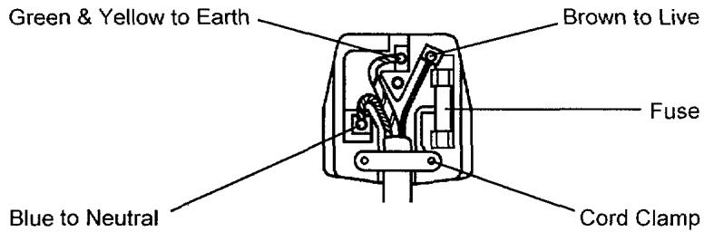
As these colours may not correspond with the coloured markings identifying the terminals in your plug, proceed as follows:
The wire which is coloured GREEN and YELLOW must be connected to the terminal in the plug which is marked with the letter E or by the earth symbol or coloured GREEN or GREEN and YELLOW.
The wire coloured BLUE must be connected to the terminal marked with the letter N or coloured BLUE or BLACK. The wire coloured BROWN must be connected to the terminal marked with the letter L or coloured BROWN or RED.
Before installing, read the chapter "CAUTIONS" carefully.
Checking the contents
Check whether the consignment agrees with the details in the following delivery note. Should you discover that the equipment has been damaged during transport or that the consignment does not correspond to the delivery note, notify your dealer immediately.
Delivery Note: one Monitor
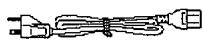
one Power Cord
this User Manual
NOTE: Keep the original packing material for future reshipment.
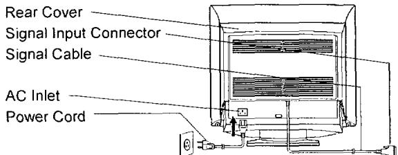
Connecting the monitor
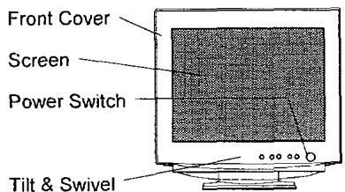
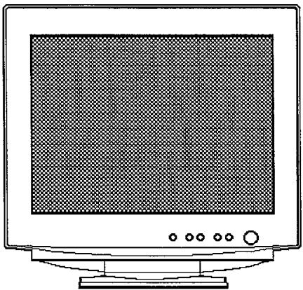
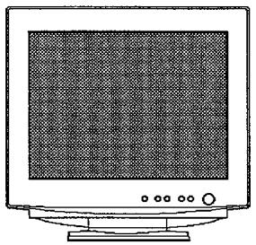
Front View
to a power outlet of the correct voltage
Rear View to the host computer
1. Installation
Install the monitor in an suitable environment.
Do not place the monitor on an unstable base.
Do not expose the monitor to rain, moisture, dust, corrosive gases, vibrations, etc. so as to prevent electrical shock or fire hazard.
Avoid placing the monitor in direct sunlight or near heating appliances.
2. Signal Cable Connection
Insert the signal input connector of the monitor to the host computer, with attention to the suitability, and secure the screws on the connector shell firmly.
3. Power Cord Connection
(1) Make sure to use the power cord meeting the safety standard of the country in which you are using the monitor.
(2) Insert the connector of a power cord to the AC Inlet of the monitor.
(3) Insert the plug of the power cord to a power outlet of the correct voltage.
Before inserting the plug of the power cord into a power outlet of the correct voltage, check that the connection portion of the power cord is clean (with no dust). Then, insert the plug of power cord into a power outlet firmly to avoid electrical shock or fire hazard.
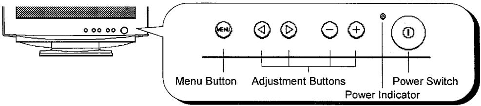

Power ON/OFF
Press the power switch, to switch the power ON or OFF. When power is ON, the power indicator lights.
NOTE:
- Turn on the monitor first, then the computer.
- After turning OFF the power switch, wait at least 5 seconds before restarting the monitor.
If this 5 second delay is not observed, the monitor may operate incorrectly.
Brightness/Contrast Adjustment
(1) Press one of the adjustment buttons when the OSD (On Screen Display) is not shown. The OSD function "EasyMenu" then shows the condition of brightness and contrast.
(2) To adjust, use the adjustment buttons / for brightness, and / for contrast.
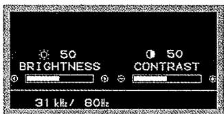
Brightness/Contrast Menu
Other Functions
(1) Press the menu button when the OSD is not shown. The OSD function "EasyMenu" then shows the main menu.
The EasyMenu has 4 sub menus (Screen Menu, Recall Menu, OSD Menu and Color Menu). You can call them by the functions of the main menu.
(2) To select the function of the menu, use the adjustment buttons 串 / 串
(3) To execute the selected function, use the adjustment buttons / in the Table 1-1 overleaf.
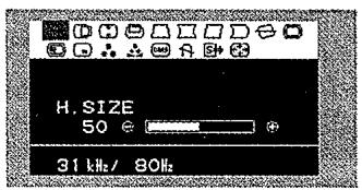
Main Menu
NOTE:
- You can select the OSD language. Use the function "LANGUAGE SELECT" of the "OSD MENU".
-
To return to the main menu from any sub menu, press the menu button.
-
To clear the OSD, press the menu button at the main menu, use the function "OSD EXIT", or wait for a definite period.
- The adjusted condition will be stored automatically at clearing the OSD.
- The OSD might be turned on and off continuously in a short period when the OSD is displayed in a certain position of the screen. This phenomenon is not a failure. Simply change the OSD position a little up or down, so that the OSD will be stable.
Table 1-1. Adjustment
| Item | Adjustment button | Function | ||
| BRIGHTNESS | ◎ | makes brightness darker. | ||
| ◎ | makes brightness brighter. | |||
| CONTRAST | ◎ | makes contrast darker excluding background. | ||
| ◎ makes contrast brighter excluding background. | ||||
| MAIN MENU | ◎ | changes to the previous mode. H. SIZE ⇒ ZOOM ⇒ OSD EXIT ⇒ DEGAUSS ⇒ DMS ⇒ COLOR MENU? ⇒ COLOR SELECT ⇒ OSD MENU? ⇒ RECALL MENU? ⇒ SCREEN MENU? ⇒ ROTATION ⇒ PIN. BALANCE ⇒ PARALLELOGRAM ⇒ PINCUSHION ⇒ TRAPEZOID ⇒ V. POSITION ⇒ V. SIZE ⇒ H. POSITION ⇒ H. SIZE | ||
| ◎ | changes to the next mode. H. SIZE ⇒ H. POSITION ⇒ V. SIZE ⇒ V. POSITION ⇒ TRAPEZOID ⇒ PINCUSHION ⇒ PARALLELOGRAM ⇒ PIN. BALANCE ⇒ ROTATION ⇒ SCREEN MENU? ⇒ RECALL MENU? ⇒ OSD MENU? ⇒ COLOR SELECT ⇒ COLOR MENU? ⇒ DMS ⇒ DEGAUSS ⇒ OSD EXIT ⇒ ZOOM ⇒ H. SIZE | |||
| H. SIZE | ◎ | shrinks horizontally. | ||
| ◎ expands horizontally. | ||||
| H. POSITION | ◎ | moves the position to the left. | ||
| ◎ moves the position to the right. | ||||
| V. SIZE | ◎ | shrinks vertically. | ||
| ◎ expands vertically. | ||||
| V. POSITION | ◎ | moves the position down. | ||
| ◎ moves the position up. | ||||
(To be continued on the next page.)
Table 1-1. Adjustment (Continued)
| Item | Adjustment button | Function | |||
| (MAIN MENU) | |||||
| ☐ TRAPEZOID | ◎ | shrinks the top side, and expands the bottom side. | |||
| ◎ | expands the top side, and shrinks the bottom side. | ||||
| ☐ PINCUSHION | ◎ | curves the left/right sides inward. | |||
| ◎ | curves the left/right sides outwards. | ||||
| ☐ PARALLELOGRAM | ◎ | tilt to the left. | |||
| ◎ | tilt to the right. | ||||
| ☐ PIN. BALANCE | ◎ | curves the left/right sides to the left. | |||
| ◎ | curves the left/right sides to the right. | ||||
| ☐ ROTATION | ◎ | rotates counter clockwise. | |||
| ◎ | rotates clockwise. | ||||
| ☐ SCREEN MENU? | ◎ | (unavailable) | |||
| ◎ | calls "SCREEN MENU". | ||||
| ☐ RECALL MENU? | ◎ | (unavailable) | |||
| ◎ | calls "RECALL MENU". | ||||
| ☐ OSD MENU? | ◎ | (unavailable) | |||
| ◎ | calls "OSD MENU". | ||||
| ☐ COLOR SELECT | ◎ | changes the colour to the previous mode. DMS⇒USER⇒5000⇒6500⇒9300⇒DMS | |||
| ◎ | changes the colour to the next mode. DMS⇒9300⇒6500⇒5000⇒USER⇒DMS | ||||
| ☐ COLOR MENU? | ◎ | (unavailable) | |||
| ◎ | calls "COLOR MENU". | ||||
| ☐ DMS | ◎ | cancelled the DMS mode. (NO) | |||
| ◎ | set the DMS mode. (YES) It increases the brightness for dynamic motion picture system. | ||||
| ☐ DEGAUSS | ◎ | (unavailable) (NO) | |||
| ◎ | executes degaussing. (YES) | ||||
(To be continued on the next page.)

Table 1-1. Adjustment (Continued)
| Item | Adjustment button | Function | |||
| (MAIN MENU) | |||||
| OSD EXIT | ○ | (unavailable) (NO) | |||
| + | clears the OSD. (YES) | ||||
| ZOOM | ○ | shrinks horizontally and vertically. | |||
| + | expands horizontally and vertically. | ||||
| SCREEN MENU | ○ | changes to the previous mode.H. MOIRE ⇒ HEMISPHERE ⇒ V. LIN. BALANCE ⇒ V. LINEARITY ⇒ BOTTOM CORNER ⇒ TOP CORNER ⇒ V. FOCUS ⇒ H. FOCUS ⇒ V. MOIRE ⇒ H. MOIRE | |||
| ○ | changes to the next mode.H. MOIRE ⇒ V. MOIRE ⇒ H. FOCUS ⇒ V. FOCUS ⇒ TOP CORNER ⇒ BOTTOM CORNER ⇒ V. LINEARITY ⇒ V. LIN. BALANCE ⇒ HEMISPHERE ⇒ H. MOIRE | ||||
| H. MOIRE | ○ | makes the operation of the horizontal moire changing circuit weaker. | |||
| + | makes the operation of the horizontal moire changing circuit stronger. | ||||
| V. MOIRE | ○ | makes the operation of the vertical moire changing circuit weaker. | |||
| + | makes the operation of the vertical moire changing circuit stronger. | ||||
(To be continued on the next page.)
NOTE:
- Moire may appear on the screen due to interference between CRT dot pitch and video signal by conditions of video image, display size, display brightness, etc. Adjust the conditions of display size, display brightness, etc., before the adjustment of moiré.
- In some cases, this function may cause deterioration of display quality, such as focus, jitter, etc.
Table 1-1. Adjustment (Continued)
| Item | Adjustment button | Function | |||
| (SCREEN MENU) | |||||
| H. FOCUS | ◎ | makes the horizontal dynamic focus weaker. | |||
| ⊕ | makes the horizontal dynamic focus stronger. | ||||
| V. FOCUS | ◎ | makes the vertical dynamic focus weaker. | |||
| ⊕ | makes the vertical dynamic focus stronger. | ||||
| TOP CORNER | ◎ | curves the left and right top corners inwards. | |||
| ⊕ | curves the left and right top corners outwards. | ||||
| BOTTOM CORNER | ◎ | curves the left and right bottom corners inwards. | |||
| ⊕ | curves the left and right bottom corners outwards. | ||||
| V. LINEARITY | ◎ | expands the top and the bottom vertically. | |||
| ⊕ | shrinks the top and the bottom vertically. | ||||
| V. LIN. BALANCE | ◎ | shrinks the top and expands the bottom vertically. | |||
| ⊕ | expands the top and shrinks the bottom vertically. | ||||
| HEMISPHERE | ◎ | set the northern hemisphere mode. (N) | |||
| ⊕ | set the southern hemisphere mode. (S) | ||||
| RECALL MENU | ◎ | changes to the previous mode. TOTAL RESET ⇌ SINGLE RECALL | |||
| ◎ | changes to the next mode. SINGLE RECALL ⇌ TOTAL RESET | ||||
| SINGLE RECALL | ◎ | (unavailable) (NO) | |||
| ⊕ | recalls the factory setting for the current signal mode only. (YES) | ||||
| TOTAL RESET | ◎ | (unavailable) (NO) | |||
| ⊕ | recalls all factory settings and delete the all user settings. (YES) To activate the TOTAL RESET command, you will begin by pressing the button ⊙. At this time the OSD background will be red. To apply the TOTAL RESET, simply press the button ⊙ again and all user data will be erased. | ||||
| OSD MENU | ◎ | changes to the previous mode. OSD H. POS. ⇒ LANGUAGE SELECT ⇒ OSD V. POS. ⇒ OSD H. POS. | |||
| ◎ | changes to the next mode. OSD H. POS. ⇒ OSD V. POS. ⇒ LANGUAGE SELECT ⇒ OSD H. POS. | ||||
| OSD H. POS. | ◎ | moves the OSD to the left. | |||
| ◎ | moves the OSD to the right. | ||||
| OSD V. POS. | ◎ | moves the OSD down. | |||
| ◎ | moves the OSD up. | ||||
| LANGUAGE SELECT | ◎ | changes to the previous mode. ENGLISH ⇒ FRANÇAIS (French) ⇒ ITALIANO (Italian) ⇒ ESPÁÑOL (Spanish) ⇒ DEUTSCH (German) ⇒ ENGLISH | |||
| ◎ | changes to the next mode. ENGLISH ⇒ DEUTSCH (German) ⇒ ESPÁÑOL (Spanish) ⇒ ITALIANO (Italian) ⇒ FRANÇAIS (French) ⇒ ENGLISH | ||||
| COLOR MENU | ◎ | changes to the previous mode. R ⇒ B ⇒ G ⇒ R | |||
| ◎ | changes to the next mode. R ⇒ G ⇒ B ⇒ R | ||||
| RED | ◎ | makes the Green and Blue stronger. When the Green or Blue reaches the upper limit, it makes the Red weaker. | |||
| ◎ | makes the Red stronger. When the Red reaches the upper limit, it makes the Green and Blue weaker. | ||||
| GREEN | ◎ | makes the Blue and Red stronger. When the Blue or Red reaches the upper limit, it makes the Green weaker. | |||
| ◎ | makes the Green stronger. When the Green reaches the upper limit, it makes the Blue and Red weaker. | ||||
| BLUE | ◎ | makes the Red and Green stronger. When the Red or Green reaches the upper limit, it makes the Blue weaker. | |||
| ◎ | makes the Blue stronger. When the Blue reaches the upper limit, it makes the Red and Green weaker. | ||||
POWER SAVING SYSTEM
This monitor complies with VESA and ENERGY STAR® power saving requirements. The power saving system works only when used with VESA DPMS compliant PC's and/or graphic controllers.
Table 1-2. Power Saving System
| VESA DPMS | Power Saving States | ||||
| Power Saving Mode | Video | H. Sync. | V. Sync. | Power | Power Indicator |
| ON | Active | Yes | Yes | 95 W (typical) | Lighting Green |
| Stand-by | Blanked | No | Yes | Less than 10 W | Lighting Orange |
| Suspend | Blanked | Yes | No | ||
| Active OFF | Blanked | No | No | Less than 3 W | |
- When to switch the power Off during the monitor is in Active OFF mode, sometimes the power indicator lighting continues a few seconds. It is not failure.
NOTE:
PLUG & PLAY
This monitor complies with VESA DDC1/2B specifications. Plug & Play is a system, by which computer, peripherals (including monitors), and operating system manufacturers comply with for this user-friendly function. It works when the monitor is connected to DDC ready computer that is running an operating system software that incorporates Plug & Play functionality.
SIGNAL CHECK
Your monitor is equipped with an automatic Signal Verification System. The Table 1-3 below outlines the operation of this system.
Table 1-3. Signal Check
| Signal Condition | Indication of OSD | Power Indicator State |
| Proper signal is detected by the monitor. | The OSD indicates the horizontal frequency and vertical frequency on the adjustment menu. | The power indicator lights green. |
| No Sync. Signal is detected by the monitor. | The OSD indicates the message “POWER SAVE” for 5 seconds after which time the unit will turn into Power Saving Mode. | After 10 seconds, the colour of the power indicator will turn to orange. |
| A video signal is applied to the monitor that is beyond the monitor scan range. | The OSD indicates the message “INVALID SCAN FREQ.” | The power indicator will be illuminated as a solid green colour. |


The following Table 1-4 is provided to assist you in common installation issues.
Table 1-4. Troubleshooting
| Symptom | Solution |
| No power | Verify the power cord is installed correctly. Press the power switch. |
| No picture | Increase Contrast and Brightness. |
| No picture and the power indicator lights orange | Check Signal Cable Connection. Check Power Connection to computer. |
| “POWER SAVE” message appears | Check Signal Cable Connection. Check Power Connection to computer. |
| “INVALID SCAN FREQ.” message appears | Check Signal Cable Connection. Check video input specification. |
| Wavy or elliptical (moire) pattern appears | Adjust unit with moire control as outlined in the Table 1-1. |
| Colour is not uniform | Activate Degauss function. |
| Environmental influences | Check to see that no magnetic appliance such as telephones, subwooers/speakers, fans, or fluorescent lighting are near the monitor. |
CRT
19 inch type picture tube, 0.22 mm horizontal dot pitch, 0.21 mm horizontal mask pitch, Invar shadow mask, Black matrix, Short persistence phosphors, Dark tint, Anti-Reflection coat.
Input Signal
Video : 0.70 Vp-p, Analogue
Sync. : Separate H/V, TTL level
Composite H/V, TTL level
Synchronisation
Horizontal : 31 - 96 kHz
Vertical : 50 - 160 Hz
Resolution
Horizontal : up to 1600 dots
Vertical : up to 1280 lines
Video Clock Frequency: 200 MHz (typical)
Viewable Image Size : 18.0 inches (458 mm), diagonal (typical)
Viewable Image Area
Horizontal : 367 mm (typical)
Vertical : 276 mm (typical)
Colour Temperature
9300:Standard colour balance,9300K
6500:Standard colour balance,6500K
5000:Standard colour balance,5000K
USER : User defined
DMS: Standard colour balance, 9300K for the DMS mode
Power Supply
AC 100 - 120 / 200 - 240 V (automatically selected)
Power Consumption : 95 W (typical) (provided with power save circuit)
Warm-up Time : 30 minutes to reach optimum performance level.
Dimensions: 448 (W) x 442 (H) x 447 (D) mm (including Tilt & Swivel Base)
Weight: 21.0 kg (approx.) (including Tilt & Swivel Base)
Environmental Condition
Operating Temperature : 5 to 35^
Operating Relative Humidity : 10 to 80 % without condensation
Storage Temperature : -20 to 60 °C
Storage Relative Humidity : 10 to 90 % without condensation
Standard Settings
Microprocessor-based preset functions can store 37 sets of geometry settings including the standard settings. The following industrial standard settings have been preprogrammed by the factory.
Table 1-5. Standard Settings
| No. | Video Mode Name (with Resolution and Vertical Frequency) | Horizontal Frequency | |||
| 1 | VGA | 640 × | 400 | -70 Hz | 31.47 kHz |
| 2 | VESA | 800 × | 600 | -85 Hz | 53.67 kHz |
| 3 | VESA | 1024 × | 768 | -85 Hz | 68.68 kHz |
| 4 | VESA | 1280 × | 1024 | -85 Hz | 91.15 kHz |
| 5 | VESA | 1600 × | 1200 | -75 Hz | 93.75 kHz |
NOTE:
- Input signals with approximately the same frequencies may be regarded as the same signal.
- The following horizontal timing conditions are recommended (at sync. H, V separate or H/V composite).
for 31kHz - 55kHz horizontal frequency:
Horizontal front porch should be more than 0.1 s
Horizontal sync. width should be within 1.0 - 3.8 s
Horizontal back porch should be more than 1.2 s
Horizontal blanking width should be more than 3.5 s
for 55kHz - 96kHz horizontal frequency:
Horizontal front porch should be more than 0.1 s
Horizontal sync. width should be within 1.0 - 3.0 s
Horizontal back porch should be more than 1.1 s
Horizontal blanking width should be more than 2.4~ s
- The following vertical timing conditions are recommended.
Vertical front porch should be more than 10~ s
Vertical sync. width should be less than 200~ s
Vertical back porch should be more than 400~ s
Vertical blanking width should be more than 450~ s
- In case the front or back porch is extremely long, or the data display time is extremely short, it may not be able to set the expected size and position.
Pin Assignment
Signal Input Connector of the Monitor
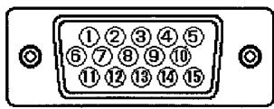
Table 1-6. Pin Assignment
| Pin No. | Signal |
| 1 | Red Video |
| 2 | Green Video (Sync. optional) |
| 3 | Blue Video |
| 4 | No pin |
| 5 | No connection |
| 6 | Red Ground |
| 7 | Green Ground |
| 8 | Blue Ground |
| 9 | +5V |
| 10 | Ground |
| 11 | No connection |
| 12 | Bi-directional Data [SDA] |
| 13 | H.Sync. (or H/V) |
| 14 | V.Sync. [VCLK] |
| 15 | Data Clock [SCL] |

TCO'99 STATEMENT

Congratulations!
You have just purchased a TCO'99 approved and labelled product! Your choice has provided you with a product developed for professional use. Your purchase has also contributed to reducing the burden on the environment and also to the further development of environmentally adapted electronics products.
This product meets the requirements for the TCO'99 scheme which provides for an international environmental and quality labelling of personal computers. The labelling scheme was developed as a joint effort by the TCO (The Swedish Confederation of Professional Employees), Svenska Naturskyddsforeningen (The Swedish Society for Nature Conservation), Statens Energimyndighet (The Swedish National Energy Administration) and SEMKO AB.
The requirements cover a wide range of issues: environment, ergonomics, usability, reduction of electric and magnetic fields, energy consumption and electrical safety.
Why do we have environmentally labelled computers?
In many countries, environmental labelling has become an established method for encouraging the adaptation of goods and services to the environment. The main problem, as far as computers and other electronics equipment are concerned, is that environmentally harmful substances are used both in the products and during their manufacture. Since it is not so far possible to satisfactorily recycle the majority of electronics equipment, most of these potentially damaging substances sooner or later enter nature.
There are also other characteristics of a computer, such as energy consumption levels, that are important from the viewpoints of both the work (internal) and natural (external) environments. Since all methods of electricity generation have a negative effect on the environment (e.g. acidic and climate-influencing emissions, radioactive waste), it is vital to save energy. Electronics equipment in offices is often left running continuously and thereby consumes a lot of energy.
What does the environmental labelling involve?
The environmental demands has been developed by Svenska Naturskyddsforeningen (The Swedish Society for Nature Conservation). These demands impose restrictions on the presence and use of heavy metals, brominated and chlorinated flame retardants, CFCs (freons) and chlorinated solvents, among other things. The product must be prepared for recycling and the manufacturer is obliged to have an environmental policy which must be adhered to in each country where the company implements its operational policy.
The energy requirements include a demand that the computer and/or display, after a certain period of inactivity, shall reduce its power consumption to a lower level in one or more stages. The length of time to reactivate the computer shall be reasonable for the user.
Below you will find a brief summary of the environmental requirements met by this product. The complete environmental criteria document may be ordered from:
TCO Development
SE-114 94 Stockholm, Sweden
Fax: +46 8 782 92 07
Email (Internet): development@tco.se
Current information regarding TCO'99 approved and labelled products may also be obtained via the Internet, using the address: http://www.tco.info.com/
Environmental requirements
Flame retardants
Flame retardants are present in printed circuit boards, cables, wires, casings and housings. Their purpose is to prevent, or at least to delay the spread of fire. Up to 30% of the plastic in a computer casing can consist of flame retardant substances. Most flame retardants contain bromine or chloride, and those flame retardants are chemically related to another group of environmental toxins, PCBs. Both the flame retardants containing bromine or chloride and the PCBs are suspected of giving rise to severe health effects, including reproductive damage in fish-eating birds and mammals, due to the bio-accumulative processes. Flame retardants have been found in human blood and researchers fear that disturbances in foetus development may occur.
The relevant TCO'99 demand requires that plastic components weighing more than 25 grams must not contain flame retardants with organically bound bromine or chlorine. Flame retardants are allowed in the printed circuit boards since no substitutes are available.
Cadmium
Cadmium is present in rechargeable batteries and in the colour-generating layers of certain computer displays. Cadmium damages the nervous system and is toxic in high doses. The relevant TCO'99 requirement states that batteries, the colour-generating layers of display screens and the electrical or electronics components must not contain any cadmium.
Mercury
Mercury is sometimes found in batteries, relays and switches. It damages the nervous system and is toxic in high doses. The relevant TCO'99 requirement states that batteries may not contain any mercury. It also demands that mercury is not present in any of the electrical or electronics components associated with the labelled unit. There is however one exception. Mercury is, for the time being, permitted in the back light system of flat panel monitors as there today is no commercially available alternative. TCO aims on removing this exception when a mercury free alternative is available.
CFCs (freons)
The relevant TCO'99 requirement states that neither CFCs nor HCFCs may be used during the manufacture and assembly of the product. CFCs (freons) are sometimes used for washing printed circuit boards. CFCs break down ozone and thereby damage the ozone layer in the stratosphere, causing increased reception on earth of ultraviolet light with e.g. increased risks of skin cancer (malignant melanoma) as a consequence.
Lead
Lead can be found in picture tubes, display screens, solders and capacitors. Lead damages the nervous system and in higher doses, causes lead poisoning. The relevant TCO'99 requirement permits the inclusion of lead since no replacement has yet been developed.
Bio-accumulative is defined as substances which accumulate within living organisms
**Lead, Cadmium and Mercury are heavy metals which are Bio-accumulative.
HITACHI
Information Media Group
Hitachi Home Electronics (Europe) Ltd.
Dukes Meadow, Millboard Road
Bourne End, Buckinghamshire, SL8 5XF U.K.
Tel: +44-1628-643349
Fax: +44-1628-643403
Tel
Fax
UK office
+44-1628-643349
+44-1628-643403
German office
+49(0)21152-915152
+49(0)21152-91594
France office
+33(0)13463-0545
+33(0)13465-0761
Belgium office
+32(0)236-39901
+32(0)236-39900
Holland
+44-1628-643349
+44-1628-643403
Switzerland office
+41(0)628-898-011
+41(0)628-964-771
Italy office
+39-02-487-86228
+39-02-487-86322
Spain office
+34(0)93-409-2549
+34(0)9349-01863
Greece office
+30(0)1-9242620
+30(0)1-9240789
Norway office
+47(0)2205-9060
+47(0)2205-9061
Sweden office
+46(0)8-5627-1100
+46(0)8-5627-1113
Finland office
+358-9455-0805
+358-9455-2152
Denmark office
+45-43-43-6050
+45-43-43-6051
Hitachi Australia Ltd.
13-15 Lyonpark Road North Ryde NSW 2113 Australia
Tel: +61-2-9888-4100
Fax: +61-2-9888-4188
- READ THE INSTRUCTIONS INSIDE CAREFULLY. KEEP THIS USER MANUAL FOR FUTURE REFERENCE.
- HITACHI
- (DJ72)
- CM776ET
- USER MANUAL
- NOTE:
- TRADEMARK ACKNOWLEDGEMENT:
- CONTENTS
- Tables:
- Sharpest Focus and Highest Contrast
- Wide-range Multi-Scanning
- Digital Picture Control Function
- Digital Colour Control Function
- Power Saving System
- EasyMenu
- Plug & Play
- CAUTION for 200 - 240V operation only
- Be careful of static electricity on CRT surface!
- Avoid frequent power ON-OFF switching!
- Be careful of generated magnetism!
- About cleaning
- FCC Statement Warning
- For the Customers in CANADA
- For the Customers in the UK
- IMPORTANT FOR UNITED KINGDOM
- WORDING FOR CLASS I EQUIPMENT INSTRUCTION BOOKS AND LABELS
- WARNING: THIS EQUIPMENT MUST BE EARTHED
- IMPORTANT
- Checking the contents
- Connecting the monitor
- Installation
- Signal Cable Connection
- Power Cord Connection
- Power ON/OFF
- Brightness/Contrast Adjustment
- Other Functions
- SIGNAL CHECK
- CRT
- Input Signal
- Synchronisation
- Resolution
- Viewable Image Area
- Colour Temperature
- Power Supply
- Environmental Condition
- Standard Settings
- Pin Assignment
- TCO'99 STATEMENT
- Congratulations!
- Why do we have environmentally labelled computers?
- What does the environmental labelling involve?
- TCO Development
- Environmental requirements
- Flame retardants
- Cadmium
- Mercury
- CFCs (freons)
- Lead
Brand : HITACHI
Model : CM776ET
Category : Computer monitor