
42PD5300 - Plasma TV HITACHI - Free user manual and instructions
Find the device manual for free 42PD5300 HITACHI in PDF.
| Product type | Plasma television |
| Brand | HITACHI |
| Model | 42PD5300 |
| Screen size | 42 inches (diagonal 1059 mm) |
| Resolution | 1024 (H) x 1024 (V) pixels |
| Net dimensions (without speakers or stand) | 1030 (W) x 636 (H) x 91 (D) mm |
| Net weight | 34.9 kg |
| Power supply | AC 100-240 V, 50/60 Hz |
| Power consumption (operating) | 365 W |
| Standby power consumption | Less than 3 W |
| Audio output | 12 W + 12 W (6 Ω) |
| Main video inputs | RGB1 DVI-D, RGB2 D-sub 15-pin, composite and component video options via optional video unit |
| Main features | High-performance digital processor, remote control, ENERGY STAR energy saving system, multiple image modes (Full, Normal, Zoom, Real), advanced image and audio settings |
| Optional accessories | Desktop stand CMPAD25, speakers CMPAS14, video unit CMPAVW1 |
| Screen cleaning | Soft cloth slightly dampened with hot water, then wipe dry; mild detergent if necessary. Do not use abrasive products. |
| Installation precautions | Maintain at least 10 cm clearance around the unit for ventilation; use an approved stand; do not obstruct ventilation openings. |
| Safety | Do not disassemble, do not expose to moisture, unplug if problems occur, use correct outlet, do not place heavy objects on the cord. |
| Warranty | 12 months from date of purchase (defective parts due to manufacturing defect), installation and use according to the guide. |
Frequently Asked Questions - 42PD5300 HITACHI
User questions about 42PD5300 HITACHI
0 question about this device. Answer the ones you know or ask your own.
Ask a new question about this device
Download the instructions for your Plasma TV in PDF format for free! Find your manual 42PD5300 - HITACHI and take your electronic device back in hand. On this page are published all the documents necessary for the use of your device. 42PD5300 by HITACHI.
USER MANUAL 42PD5300 HITACHI
Colour Plasma Display Monitor
Model PW1
32PD5000
42PD5000
42PMA500
CMP4214E
System Name
32PD5000/42PD5000
32PD5100/42PD5100
32PD5200/42PD5200
USER'S MANUAL
MANUEL UTILISATEUR
READ THE INSTRUCTIONS INSIDE CAREFULLY.
KEEP THIS USER'S MANUAL FOR FUTURE REFERENCE.
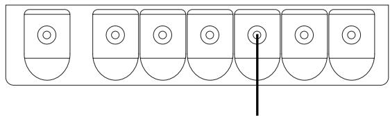
For future reference, record the serial number of your monitor.
SERIAL NO.
The serial number is located on the rear of the monitor.
This monitor is ENERGY STAR® compliant when used with a computer equipped with VESA DPMS.
The ENERGY STAR® emblem does not represent EPA endorsement of any product or service.
As an ENERGY STAR® Partner, Hitachi,Ltd. has determined that this product meets the ENERGY STAR® guidelines for energy efficiency.

NOTE:
The information in this manual is subject to change without notice. The manufacturer assumes no responsibility for any errors that may appear in this manual.
TRADEMARK ACKNOWLEDGEMENT
VGA and XGA are registered trademarks of International Business Machines Corporation.
APPLE and Macintosh are registered trademarks of Apple Computer, Inc.
VESA is a trademark of a nonprofit organization, Video Electronics Standard Association.
All brand or product names are trademarks or registered trademarks of their respective holders.
REMARQUE:
TruBass TRUBass by SRS (O)
CHARACTERISTIQUES DU PRODUIT 27
CHARACTERISTIQUES DU PRODUIT
CARACTERISTIQUES DU PRODUIT (suite)
INSTRUCTIONS D'OPÉRATION (suite)
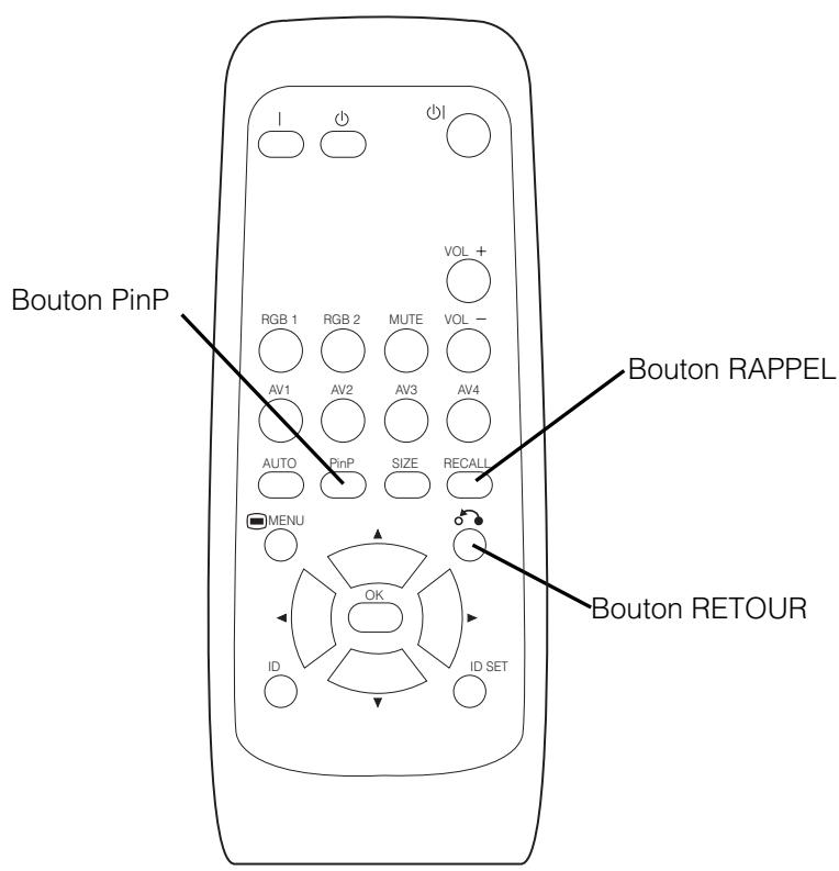
Bouton RAPPEL
Affichage de MULTI PICTURE (MULTI IMAGE)
| Principal | Secondaire |
REMARQUES
INSTRUCTIONS D'OPÉRATION (suite)
MENU IMAGE (suite)
INSTRUCTIONS D'OPÉRATION (suite)
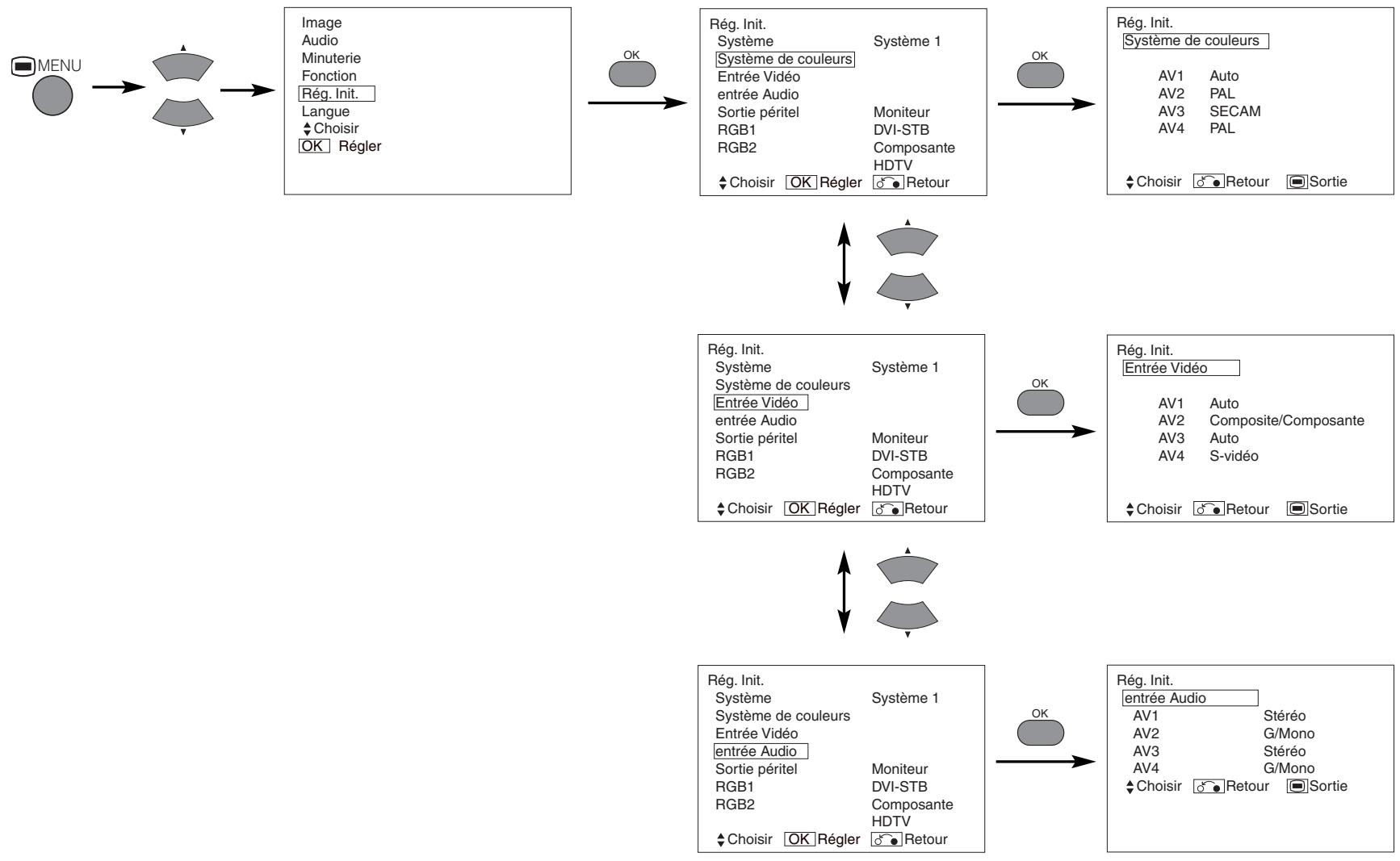
MENURÉGLAGE INITIAL
CARACTÉRISTIQUES DU PRODUIT
CARACTERISTIQUES DU PRODUIT (suite)
| Principal | Secondaire |
4 Quatre Images
| Entrée terminal | AV1~AV4 | AV1, AV2 | RGB1 | RGB2 | TELETEXTE | ||||||
| SecondairePrincipal | PALSECAM | NTSC3,58NTSC4,43 | 576i576p | 480i480p | 1080i/50 | 1080i/60 | 720p/60 | STB | Composante | ||
| AV1~AV4 | PAL, SECAM | ○ | ○ | ||||||||
| NTSC3,58/4,43 | ○ | ○ | |||||||||
| AV1AV2 | 576i, 576p | ○ | ○ | ||||||||
| 480i, 480p | ○ | ○ | |||||||||
| 1080i/50 | ○ | ○ | |||||||||
| 1080i/60 | ○ | ○ | |||||||||
| 720p/60 | ○ | ○ | |||||||||
| RGB1 | STB | ||||||||||
| RGB2 | Composante | ○ | ○ | ||||||||
| Principal | Secondaire 1 |
| Secondaire 2 | |
| Secondaire 3 |
( :disponible)
INSTRUCTIONS D'OPÉRATION (suite)
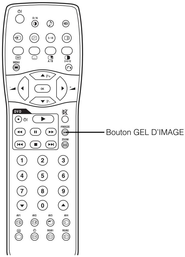
Gel D'images
INSTRUCTIONS D'OPÉRATION (suite)
MENURÉGLAGE INITIAL (Suite)
INSTRUCTIONS D'OPÉRATION (suite)
AUTRES FONCTIONS (Suite)
CHARACTERISTIQUES DU PRODUIT
Hitachi Plasma TV Horizontal Wall-mount Unit
Model
PWT001
Installation Instructions
Thank you for purchasing the Hitachi Plasma TV Wall-mount Unit.
To ensure correct usage, please read this instruction manual thoroughly. After reading, please store this manual in a safe place for future reference.
This plasma TV wall-mount unit is for use with the following models:
HITACHI Plasma TV CL32-PD2100, CL37-PD2100, CL42-PD2100, 32PD5100, 42PD5100, 42PMA500
32PD5000, 32PD5200, 32PD5300, 37PD5200, 42PD5000, 42PD5200, 42PD5300, CMP4211/2, CMP4213/4
Special techniques are necessary for installation of the plasma TV.
Do not attempt to perform this work by yourself.
Request an installation specialist to install this unit.
This company assumes absolutely no responsibility for injuries and damages that may occur due to improper installation and handling.
Please remember that if you remove the plasma TV set from the wall later, you will find the screw holes and anchor bolts for the mounting unit left on the wall. Also note that a long use of the plasma TV set may discolor the wall around it due to its heat and air flow.
To dealers and shops
- To ensure customer safety, be sure to design the installation location so that the strength is sufficient to withstand the weight of both the plasma TV and the wall-mount unit.
Always use at least two persons for all installations. - Fully tighten all of the mounting screws as specified in the installation instructions.
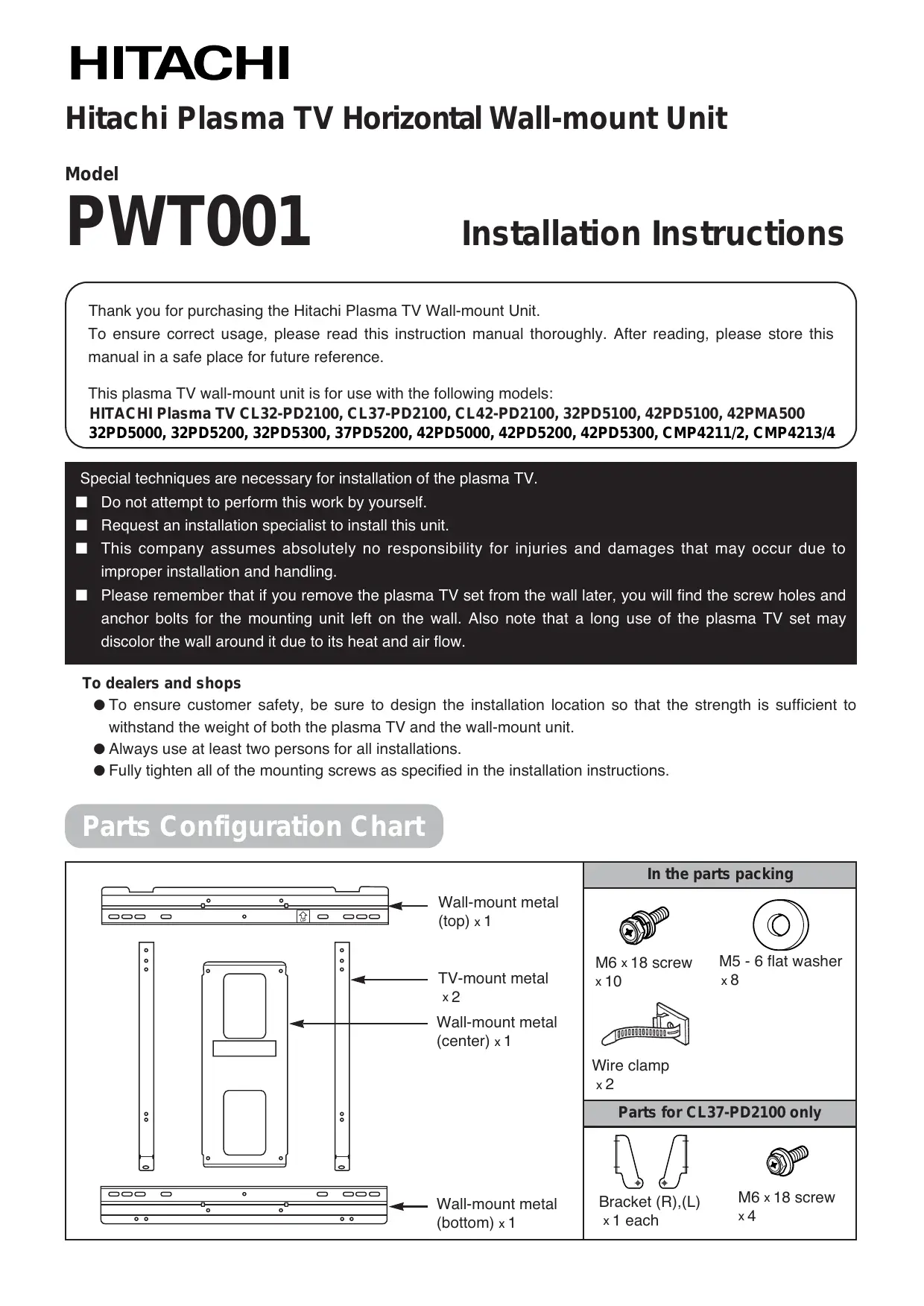
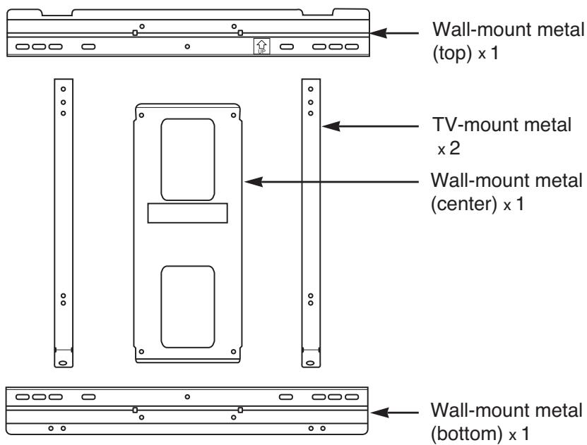
Parts Configuration Chart
In the parts packing

M6 x 18 screw x 10

M5 - 6 flat washer × 8
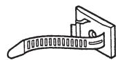
Wire clamp x2
Parts for CL37-PD2100 only
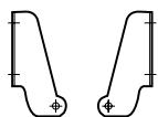
Bracket (R),(L) x1 each

M6 x 18 screw x4
Usage cautions to ensure correct usage
Symbols
The following symbols are used to ensure safe usage of the product, to prevent danger to yourself and other parties and to prevent damage to property.

WARNING
This symbol indicates that incorrect handling due to ignoring this symbol can result in the possibility of personal injury or even death.

CAUTION
This symbol indicates that incorrect handling due to ignoring this symbol can result in the possibility of personal injury and physical damage.

This symbol indicates additional cautions (including warnings).

Caution (general)

This symbol indicates forbidden actions.

Forbidden (general)

Disassembly prohibited

This symbol indicates required actions.

Required (general)

Indicates that the power plug is to be disconnected from the power outlet.
Safety Cautions

WARNING

Disconnect the power plug from the power outlet.

Contact your local dealer.
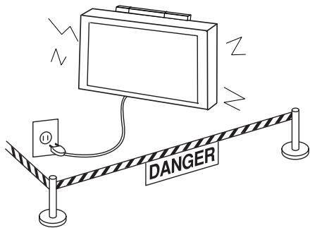
■ When a malfunction occurs, disconnect the power plug from the power outlet and take measures to prevent other people coming near the plasma TV.
In the cases such as
- The plasma TV is loose and vibrates to an extreme degree,
- Mounting screws or parts are loose or missing,
failure to take appropriate actions can result in injury.
Perform the following actions immediately whenever a malfunction occurs.
①Turn off the plasma TV power switch.
② Disconnect the power plug from the power outlet.
③ Surround the area with rope, etc., to prevent other people coming near.
④ Contact your local dealer.

Handling by other than professional contractors is prohibited.
■ Ask your dealer to install, move or adjust the angle of the wall-mount unit.
Incorrect installation or adjustment can cause the plasma TV to fall.

WARNING


The wall where the wall-mount unit is to be installed must be capable of long-term support of the total load of the plasma TV and wall-mount unit. Measures should also be taken to ensure sufficient strength to withstand the force of earthquakes, vibration and other external forces.
Incorrect installation can cause the plasma TV to fall and cause injury.
Total load of the (plasma TV + wall-mount unit)
= 26kg... CL32 - PD2100
34kgCL37-PD2100
37kg...CL42-PD2100
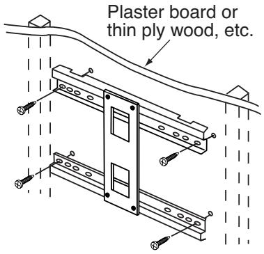
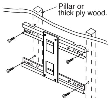
- Installation on a wooden wall
Always install so that the load is supported by a pillar. If the strength of the pillar is insufficient, add reinforcement. Do not install on decorative posts or plaster board.
- Installation on a concrete wall
Use commercially available anchors that are capable of fully supporting the load of the plasma TV.

CAUTION
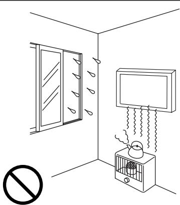
Avoid installing in locations where the temperature and humidity are excessively high, and where contact with water is possible.
These can result in fire or electrical shock.
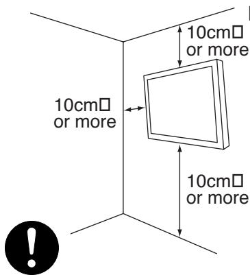
- Do not block the ventilation holes.
- Also provide sufficient clearance in regard to the surroundings to avoid blocking the ventilation.
The internal temperature could elevate and possibly result in fire.
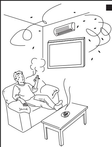
Do not install close to an air-conditioner intake or outlet.
Do not install in locations where there is excessive amounts of dust, oily smoke or tobacco smoke.
Fire could result.
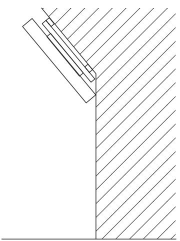
Install only on a vertical surface. Avoid sloped surface. Also, do not install facing upward.
The internal temperature could elevate and possibly result in fire. Injury or damage could also result from falling.


| CAUTION | ||
| ■ Do not install in locations where there is excessive vibration or impact. Injury and damage could result from falling. | ■ Do not install where there is direct sunlight and other strong light. Strong light could result in eye fatigue during usage. | |
Installing
| WARNING | ||
| ■ Use the specified bolts and screws in the specified places and tighten firmly. Failure to do this could cause injury if the plasma TV falls. | ■ Make sure the TV-mount metals and wall-mount metals are firmly engaged. Failure to do so could cause the plasma TV to fall. | |
| ■ Do not alter any of the parts. And do not use broken parts. This could result in injury due to the plasma TV falling. | ■ Always use at least two people to perform the installation work. Injury could result from dropping heavy objects. | |
| ■ Use care to prevent the fingers being caught. | ||
Installation Method
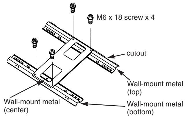
Assembling the wall-mount metals
■ Assemble the wall-mount metal (Top), (Center) and (Bottom) with 4 M6 x 18 screws.
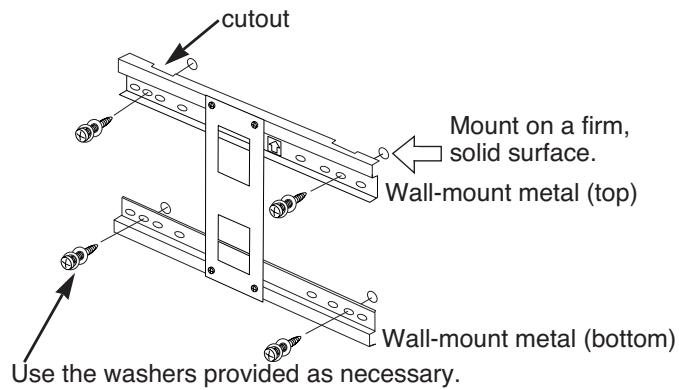
Mounting the wall-mount unit on the wall
- Prepare at least four sets of commercially available anchors and screws, etc., for various types of walls.
- Carefully read the safety cautions concerning installation locations as described in this instruction manual and then select a suitable location for installation.
-
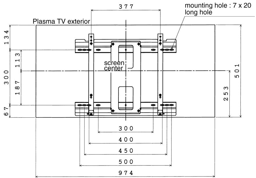
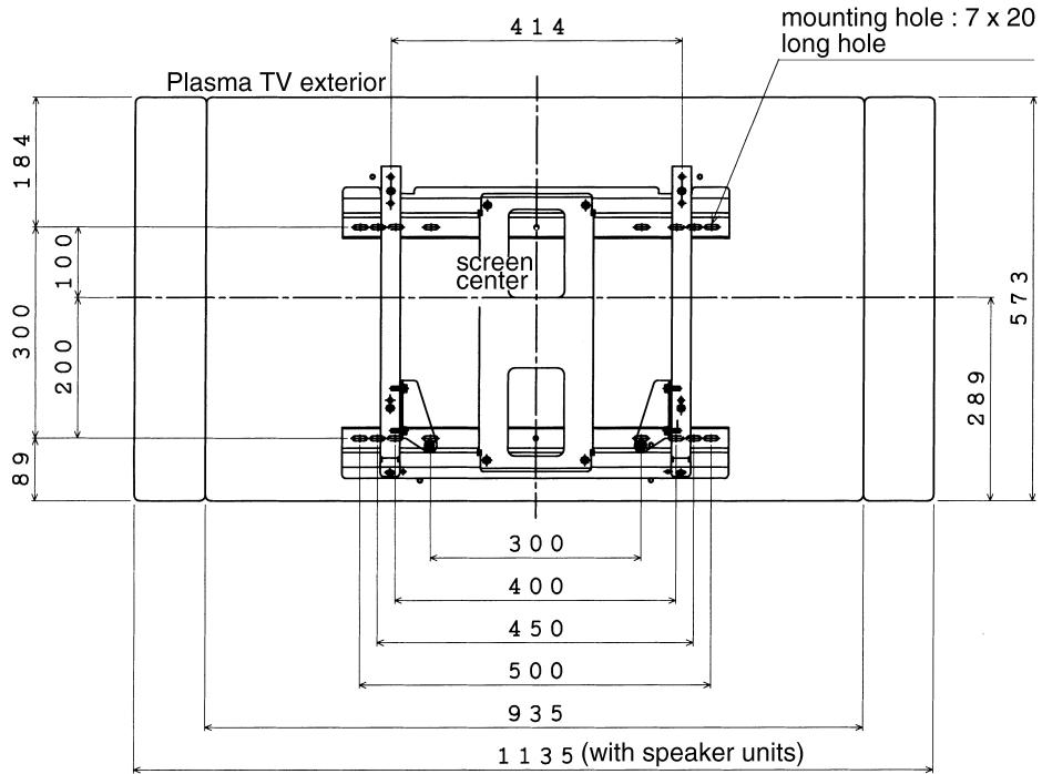
The relationship between the plasma TV exterior and center, and the positions of the wall-mount unit mounting holes is shown in the diagram for the various models. Install the anchors in the wall as shown in the diagram and process the holes as necessary.
-
Make sure that the strengths of the wall and the screws are fully sufficient.
32 inch
37 inch
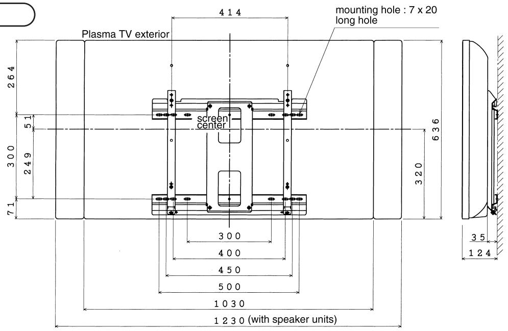
- Fasten the wall-mount unit securely to the wall.
- Clamp to two or more of the long slotted holes in the upper and lower parts of each wall-mounting metal in a well-balanced manner.
-
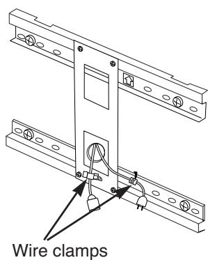
Dressing the cables
-
When passing the plasma TV power cord and signal cables behind the plasma TV, use wire clamps, etc., to prevent cable damage.
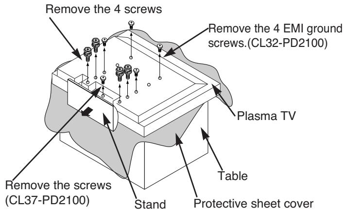
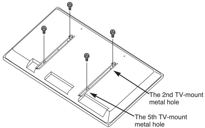
Mounting the TV-mount metals on the plasma TV
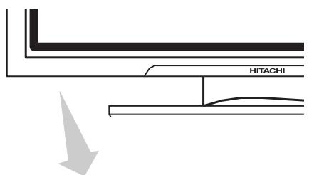
1. Remove the stand.
① Place a protective sheet cover on the top of a table and place the plasma TV on the cover with the back side upward.
② Remove the 4 EMI ground screws. (for CL32-PD2100 only.)
③ Remove the 4 or 5 (CL37-PD2100) screws fastening the stand and remove the stand in the direction indicated by the arrow → mark.
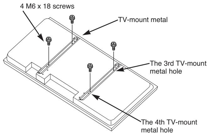
2. Installing the TV-mount metals
CL32-PD2100
■Fasten the two TV-mount metals to the back of the plasma TV with 4 M6 x 18 screws.
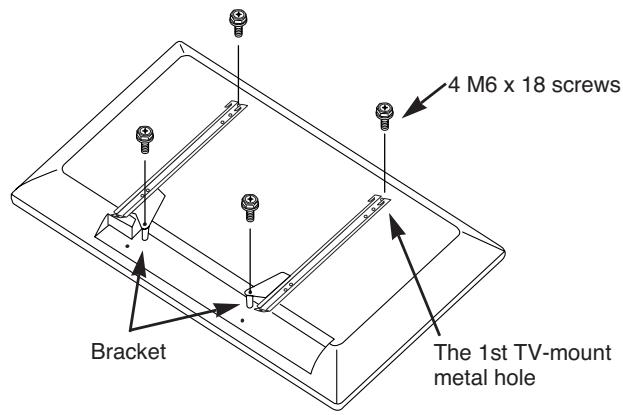
CL37-PD2100
① Fasten the bracket (R), (L) to the TV mount metal with 4 M6 × 18 screws.
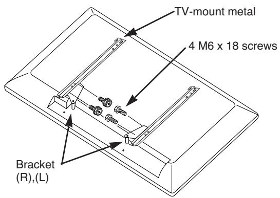
② Fasten the two TV-mount metals to the back of the plasma TV with 4 M6 × 18 screws.
CL42-PD2100
■Fasten the two TV-mount metals to the back of the plasma TV with 4 M6 x 18 screws.
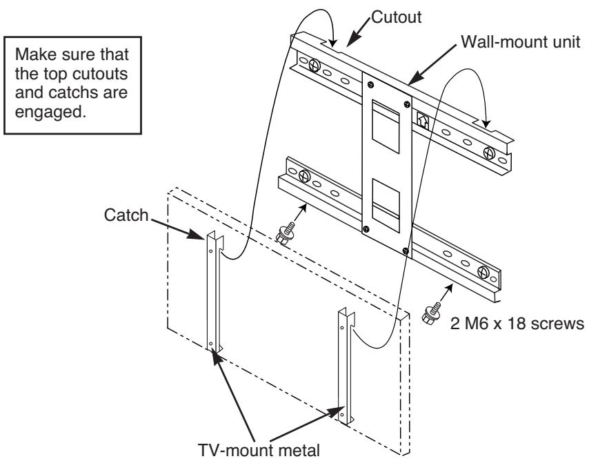
Installing the plasma TV on the wall mount
① Hang the TV-mount metal catches on the wall-mount unit cutouts.
(2) Fasten with 2 M 6 × 18 screws from the bottom.
③ After make sure all mouting works are completely done, connect power cord and signal cables.
The plasma TV should always be carried by at least two people.
- Disconnect the plasma TV power cord and all cables.
Product Specifications
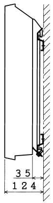
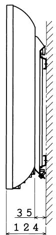
External Dimensions
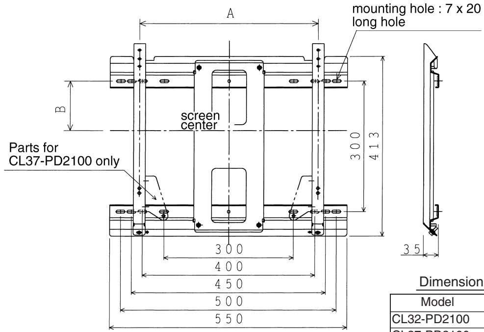
Dimension (A),(B)
| Model | A | B |
| CL32-PD2100 | 377 | 113 |
| CL37-PD2100 | 414 | 100 |
| CL42-PD2100 | 414 | 51 |
| Mass | 2.6kg |
| Main material | Steel sheet |
| Surface treatment | Black electrodeposited baked paint |
| Angle adjustment | Vertical fix |
| Products mounted | Hitachi Plasma TV CL32-PD2100 , CL37-PD2100 , CL42-PD2100 |
Garantie
International Sales Division
THE HITACHI ATAGO BUILDING,
No. 15-12 Nishi Shinbashi, 2 - Chome, Minato - Ku, Tokyo 105-8430, Japan.
Tel: 03 35022111
HITACHI EUROPE LTD,
Whitebrook Park
Lower Cookham Road
Maidenhead
Berkshire
SL6 8YA
UNITED KINGDOM
Tel: 01628 643000
Fax: 01628 643400
Email: consumer-service@hitachi-eu.com
HITACHI EUROPE S.A.
364 Kifissias Ave. & 1, Delfon Str.
152 33 Chalandri
Athens
GREECE
Tel: 1-6837200
Fax: 1-6835964
Email: service.hellas@hitachi-eu.com
HITACHI EUROPE GmbH
Munich Office
Dornacher Strasse 3
Email: HSE-DUS.service@hitachi-eu.com
HITACHI EUROPE S.A.
Gran Via Carlos III, 86, planta 5
Email: customerservice.italy@hitachi-eu.com
HITACHI Europe AB
Box 77 S-164 94 Kista
SWEDEN
Tel: +46 (0) 856271100
Fax: +46 (0) 8562711 13
Email: csgswe@hitachi-eu.com
HITACHI EUROPE S.A.S
Lyon Office
B.P. 45, 69671 BRON CEDEX
FRANCE
Tel: 04 72 14 29 70
Fax: 04 72 14 29 99
HITACHI EUROPE LTD (Norway) AB
STRANDVEIEN 18
1366 Lysaker
NORWAY
Tel: 67 5190 30
Fax:67519032
Email: csgnor@hitachi-eu.com
HITACHI EUROPE AB
Egebaekgård
Egebækvej 98
DK-2850 Nærum
DENMARK
Tel: +45 43 43 6050
Fax: +45 43 60 51
Email: csgnor@hitachi-eu.com
HITACHI EUROPE AB
Neopoli / Niemenkatu 73
FIN-15140 Lahti
FINLAND
Tel: +358 3 8858 271
Fax: +358 3 8858 272
Email: csgnor@hitachi-eu.com
Hitachi Europe Ltd
Bergensesteenweg 421
1600 Sint-Pieters-Leeuw
BELGIUM
Tel: +32 2 363 99 01
Fax: +32 2 363 99 00
Email: sofie.van.bom@hitachi-eu.com
HITACHI EUROPE LTD
Na Sychrove 975/8
101 27 Praha 10 - Bohdalec
CZECH REPUBLIC
Tel: +420 267 212 383
Fax: +420 267 212 385
Email: csgnor@hitachi-eu.com
- NOTE:
- REMARQUE:
- TruBass TRUBass by SRS (O)
- CHARACTERISTIQUES DU PRODUIT 27
- CHARACTERISTIQUES DU PRODUIT
- CARACTERISTIQUES DU PRODUIT (suite)
- INSTRUCTIONS D'OPÉRATION (suite)
- Affichage de MULTI PICTURE (MULTI IMAGE)
- REMARQUES
- MENU IMAGE (suite)
- MENURÉGLAGE INITIAL
- CARACTÉRISTIQUES DU PRODUIT
- Gel D'images
- MENURÉGLAGE INITIAL (Suite)
- AUTRES FONCTIONS (Suite)
- Hitachi Plasma TV Horizontal Wall-mount Unit
- PWT001
- Installation Instructions
- To dealers and shops
- Parts Configuration Chart
- In the parts packing
- Parts for CL37-PD2100 only
- Usage cautions to ensure correct usage
- Symbols
- WARNING
- CAUTION
- Safety Cautions
- Installation Method
- Assembling the wall-mount metals
- Mounting the wall-mount unit on the wall
- inch
- inch
- Mounting the TV-mount metals on the plasma TV
- Remove the stand.
- Installing the TV-mount metals
- CL32-PD2100
- CL37-PD2100
- CL42-PD2100
- Installing the plasma TV on the wall mount
- Product Specifications
- External Dimensions
- Garantie
Brand : HITACHI
Model : 42PD5300
Category : Plasma TV