
TB425CS - Brush cutter MTD - Free user manual and instructions
Find the device manual for free TB425CS MTD in PDF.


| Product Type | 4-cycle gas trimmer |
| Brand | MTD |
| Model | TB425CS |
| Engine | 4-cycle, air-cooled |
| Displacement | 26.2 cc |
| Ignition Type | Electronic |
| Lubrication | SAE 30 oil |
| Engine Oil Capacity | 100 ml |
| Fuel Tank Capacity | 355 ml |
| Cutting Diameter | 43.18 cm |
| Line Diameter | 2.41 mm |
| Weight (without fuel) | 6 kg |
| Clutch | Centrifugal |
| Operating Speed | 6,800 - 9,300 rpm |
| Idle Speed | 3,000 - 3,600 rpm |
| Spark Plug Gap | 0.655 mm |
| EZ-Link™ System | Compatible with optional attachments |
| Safety Protection | Cutting attachment guard, spark arrester |
| Starter Type | Automatic rewind |
| Line Advance Mechanism | SpeedSpool® bump head |
| Drive Shaft | Aluminum tube (EZ-Link™) |
| Warranty | 2 years (parts and labor) |
Frequently Asked Questions - TB425CS MTD
User questions about TB425CS MTD
0 question about this device. Answer the ones you know or ask your own.
Ask a new question about this device
Download the instructions for your Brush cutter in PDF format for free! Find your manual TB425CS - MTD and take your electronic device back in hand. On this page are published all the documents necessary for the use of your device. TB425CS by MTD.
USER MANUAL TB425CS MTD
Content Page
Calling Customer Support 2
Rules for Safe Operation 3
Know Your Unit 6
Assembly Instructions 7
Oil and Fuel Information 8
Starting/Stopping Instructions 10
Operating Instructions 11
Maintenance and Repair Instructions 13
Cleaning and Storage 21
Accessories and Replacement Parts 21
Troubleshooting Chart 22
Specifications. 23
Warranty Information 26
Parts List. Inside Back Cover
NOTE: For users on U.S. Forest Land and in the states of California, Maine, Oregon and Washington. All U.S. Forest Land and the state of California (Public Resources Codes 4442 and 4443), Oregon and Washington require, by law that certain internal combustion engines operated on forest brush and/or grass-covered areas be equipped with a spark arrester, maintained in effective working order, or the engine be constructed, equipped and maintained for the prevention of fire. Check with your state or local authorities for regulations pertaining to these requirements. Failure to follow these requirements could subject you to liability or a fine. This unit is factory equipped with a spark arrester. If it requires replacement, Accessory Part #180890 Spark Arrestor Screen is available by contacting the service department.
FINDING MODEL NUMBER
This operator's manual is an important part of your new trimmer. It will help you assemble, prepare and maintain the unit for best performance. Please read and understand what it says.
Before you start assembling your new equipment, please locate the model plate on the equipment and copy the information from it in the space provided below. This information is very important if you need help from our Customer Support Department or an authorized dealer.
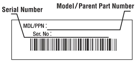
Copy the model / parent part number here:
Copy the serial number here:
CALLING CUSTOMER SUPPORT
If you have difficulty assembling this product or have any questions regarding the controls, operation or maintenance of this unit, please call the Customer Support Department.

Call 1-(330)-558-7220 or 1-(866)-840-6483 to reach a Customer Support representative. Please have your unit's model number and serial number ready when you call. See the previous section to locate this information. You will be asked to enter the serial number in order to process your call.
For more details about your unit, visit our website at www.troybilt.com
The purpose of safety symbols is to attract your attention to possible dangers. The safety symbols, and their explanations, deserve your careful attention and understanding. The safety warnings do not by themselves eliminate any danger. The instructions or warnings they give are not substitutes for proper accident prevention measures.
SYMBOL MEANING

SAFETY ALERT SYMBOL: Indicates danger, warning or caution. Attention is required in order to avoid serious personal injury. May be used in conjunction with other symbols or pictographs.
NOTE: Advises you of information or instructions vital to the operation or maintenance of the equipment.
California Proposition 65 Warning:

WARNING

THE ENGINE EXHAUST FROM THIS PRODUCT CONTAINS CHEMICALS KNOWN TO THE STATE OF CALIFORNIA TO CAUSE CANCER, BIRTH DEFECTS OR OTHER REPRODUCTIVE HARM.
READ ALL INSTRUCTIONS
BEFORE OPERATING
- Read the instructions carefully. Be familiar with the controls and proper use of the unit.
- Do not operate this unit when tired, ill or under the influence of alcohol, drugs or medication.
- Children and teens under the age of 15 must not use the unit, except for teens guided by an adult.
- Inspect the unit before use. Replace damaged parts. Check for fuel leaks. Make sure all fasteners are in place and secure. Replace cutting attachment parts that are cracked, chipped or damaged in any way. Make sure the cutting attachment is properly installed and securely fastened. Be sure the cutting attachment shield is properly attached, and positioned as recommended. Failure to do so can result in personal injury to the operator and bystanders, as well as damage to the unit.
- Use only 0.095 inch (2.41 mm) diameter Genuine Factory Parts™ replacement line. Never use metal-reinforced line, wire or rope. These can break off and become dangerous projectiles.
- Be aware of the risk of injury to the head, hands and feet.
SYMBOL MEANING

DANGER: Failure to obey a safety warning will result in serious injury to yourself or to others. Always follow the safety precautions to reduce the risk of fire, electric shock and personal injury.

WARNING: Failure to obey a safety warning can result in injury to yourself and others. Always follow the safety precautions to reduce the risk of fire, electric shock and personal injury.

CAUTION: Failure to obey a safety warning may result in property damage or personal injury to yourself or to others. Always follow the safety precautions to reduce the risk of fire, electric shock and personal injury.
- Clear the area to be cut before each use. Remove all objects such as rocks, broken glass, nails, wire or string. They can be thrown or become entangled in the cutting attachment. Clear the area of children, bystanders, and pets. At a minimum, keep all children, bystanders and pets outside a 50-foot (15 m.) radius; there still may be a risk to bystanders from thrown objects. Bystanders should be encouraged to wear eye protection. If you are approached, stop the engine and cutting attachment immediately.
- Squeeze the throttle control and check that it returns automatically to the idle position. Make all adjustments or repairs before using unit.
- This unit was not designed to be used as a brushcutter. Do not attach or operate this unit with any type of brushcutting blade or brushcutting attachment.
SAFETY WARNINGS FOR GAS TRIMMERS

WARNING: Gasoline is highly flammable, and its vapors can explode if ignited. Take the following precautions:
- Store fuel only in containers specifically designed and approved for the storage of such materials.
- Always stop the engine and allow it to cool before filling the fuel tank. Never remove the cap of the fuel tank, or add fuel, when the engine is hot. Never operate the unit without the fuel cap securely in place. Loosen the fuel tank cap slowly to relieve any pressure in the tank.
- Add fuel in a clean, well-ventilated outdoor area where there are no sparks or flames. Slowly remove the fuel cap only after stopping engine. Do not smoke while fueling or mixing fuel. Wipe up any spilled fuel from the unit immediately.
- Avoid creating a source of ignition for spilled fuel. Do not start the engine until fuel vapors dissipate.
- Move the unit at least 30 feet (9.1 m) from the fueling source and site before starting the engine. Do not smoke. Keep sparks and open flames away from the area while adding fuel or operating the unit.
- Never start or run the unit inside a closed room or building. Breathing exhaust fumes can kill. Operate this unit only in a well ventilated outdoor area.
- Wear safety glasses or goggles that are marked as meeting ANSI Z87.1-1989 standards. Also wear ear/hearing protection when operating this unit. Wear a face or dust mask if the operation is dusty. Long sleeve shirts are recommended.
- Wear heavy, long pants, boots and gloves. Do not wear loose clothing, jewelry, short pants, sandals or go barefoot. Secure hair above shoulder level.
- The cutting attachment shield must always be in place while operating the unit. Do not operate unit without both trimming lines extended, and the proper line installed. Do not extend the trimming line beyond the length of the shield.
- This unit has a clutch. The cutting attachment remains stationary when the engine is idling. If it does not, have the unit adjusted by an authorized service technician.
- Adjust the J-handle to your size to provide the best grip.
- Be sure the cutting attachment is not in contact with anything before starting the unit.
- Use the unit only in daylight or good artificial light.
- Avoid accidental starting. Be in the starting position whenever pulling the starter rope. The operator and unit must be in a stable position while starting. See Starting/Stopping Instructions.
- Use the right tool. Only use this tool for the purpose intended.
- Do not overreach. Always keep proper footing and balance.
- Always hold the unit with both hands when operating. Keep a firm grip on both the front and rear handle or grips.
- Keep hands, face, and feet at a distance from all moving parts. Do not touch or try to stop the cutting attachment when it is rotating.
-
Do not touch the engine or muffler. These parts get extremely hot from operation. They remain hot for a short time after you turn off the unit.
-
Do not operate the engine faster than the speed needed to cut, trim or edge. Do not run the engine at high speed when you are not cutting.
- Always stop the engine when cutting is delayed or when walking from one cutting location to another.
- If you strike or become entangled with a foreign object, stop the engine immediately and check for damage. Do not operate before repairing damage. Do not operate the unit with loose or damaged parts.
- Stop and switch the engine to off for maintenance, repair, or for changing the cutting attachment or other attachments.
Use only Genuine Factory Parts™ replacement parts and accessories for this unit. These are available from your authorized service dealer. Use of any unauthorized parts or accessories could lead to serious injury to the user, or damage to the unit, and void your warranty.
- Keep unit clean of vegetation and other materials. They may become lodged between the cutting attachment and shield.
- To reduce fire hazard, replace faulty muffler and spark arrestor, keep the engine and muffler free from grass, leaves, excessive grease or carbon build up.
OTHER SAFETY WARNINGS
- Never store the unit, with fuel in the tank, inside a building where fumes may reach an open flame or spark.
- Allow the engine to cool before storing or transporting. Be sure to secure the unit while transporting.
- Store the unit in a dry area, locked up or up high to prevent unauthorized use or damage, out of the reach of children.
- Never douse or squirt the unit with water or any other liquid. Keep handles dry, clean and free from debris. Clean after each use. See the Cleaning and Storage instructions.
- Keep these instructions. Refer to them often and use them to instruct other users. If you loan someone this unit, also loan them these instructions.
SAVE THESE INSTRUCTIONS
SAFETY AND INTERNATIONAL SYMBOLS
This operator's manual describes safety and international symbols and pictographs that may appear on this product. Read the operator's manual for complete safety, assembly, operating and maintenance and repair information.

SYMBOL
MEANING
- SAFETY ALERT SYMBOL
Indicates danger, warning, or caution. May be used in conjunction with other symbols or pictographs.

WARNING - READ OPERATOR'S MANUAL
Read the Operator's Manual(s) and follow all warnings and safety instructions. Failure to do so can result in serious injury to the operator and/or bystanders.

- WEAR EYE AND HEARING PROTECTION
WARNING: Thrown objects and loud noise can cause severe eye injury and hearing loss. Wear eye protection meeting ANSI Z87.1-1989 standards and ear protection when operating this unit. Use a full face shield when needed.

- KEEP BYSTANDERS AWAY
WARNING: Keep all bystanders, especially children and pets, at least 50 feet (15 m.) from the operating area.

- UNLEADED FUEL
Always use clean, fresh unleaded fuel.

OIL
Refer to operator's manual for the proper type of oil.
SYMBOL
MEANING
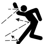
- THROWN OBJECTS AND ROTATING CUTTER CAN CAUSE SEVERE INJURY
WARNING: Do not operate without the cutting attachment shield in place. Keep away from the rotating cutting attachment.

ON/OFF STOP CONTROL ON / START / RUN
ON/OFF STOP CONTROL OFF OR STOP
- HOT SURFACE WARNING
- Do not touch a hot muffler or cylinder. You may get burned. These parts get extremely hot from operation. When turned off they remain hot for a short time.
SHARP BLADE
WARNING: Sharp blade on cutting attachment shield. To prevent serious injury, do not touch line cutting blade.

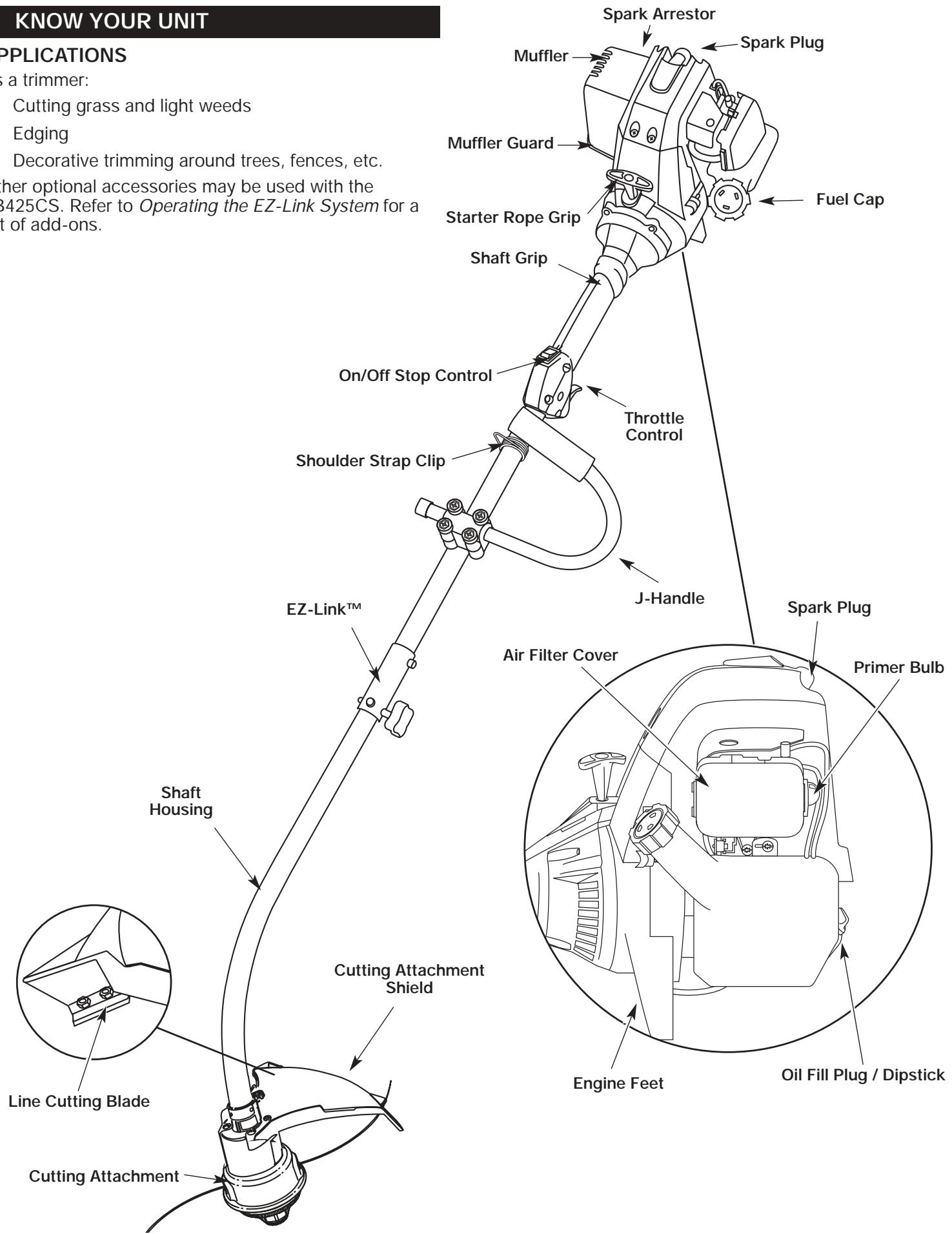
Cutting grass and light weeds
- Edging
- Decorative trimming around trees, fences, etc.
Other optional accessories may be used with the TB425CS. Refer to Operating the EZ-Link System for a list of add-ons.
ASSEMBLY INSTRUCTIONS
On some units, the J-handle may be pre-installed. In this case you must loosen screws and adjust the handle to fit the operator. Go to step 5 if the J-handle is pre-installed.
INSTALL AND ADJUST THE J-HANDLE
- Place the J-handle between the top and middle clamp pieces (Fig. 1).
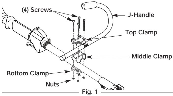
- While holding the three pieces together, install the four (4) screws through the top clamp and into middle clamp.
NOTE: The holes in the top and middle clamp will line up only when assembled correctly.
- Place the clamps and the J-handle over the shaft housing and onto the bottom clamp.
- Hold each hex nut in the bottom clamp recess with a finger. Start screws with a large Phillips screwdriver. Do not tighten until you make the handle adjustment.
- Slide the J-handle in or out until the arrow/white line on the decal touches the clamp assembly (Fig. 2). You must first loosen the screws if the handle is pre-installed.
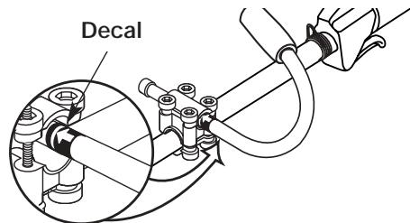
Fig. 2
- While holding the unit in the operating position (Fig. 3), position the J-handle to the location that provides you the best grip.
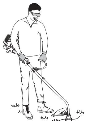
Fig. 3
- Tighten the clamp screws evenly, until the J-handle is secure.
INSTALLING THE CUTTING SHIELD
Use the following instructions if the cutting attachment shield on your unit is not installed or if you ever need to re-install it.

WARNING: Never operate the trimmer without the cutting attachment shield in place to prevent serious personal injury.
- Place the cutting attachment shield onto the shaft housing above the clamp assembly (Fig. 4).
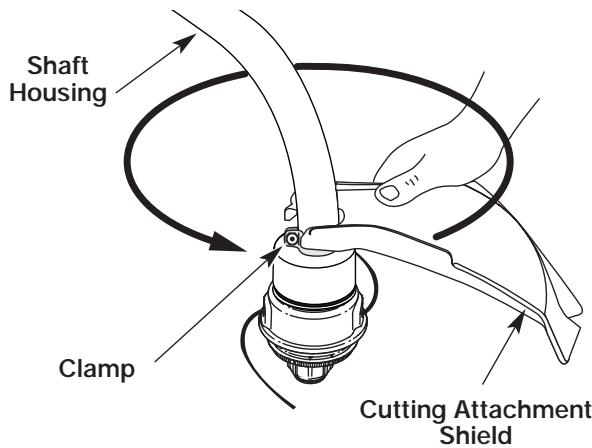
Fig. 4
- Push the cutting attachment shield down to the top of the cutting attachment assembly. Then rotate the shield until its screw holes line up with the holes in the cutting attachment. The shield guard should fit into the recessed pocket (Fig. 4).
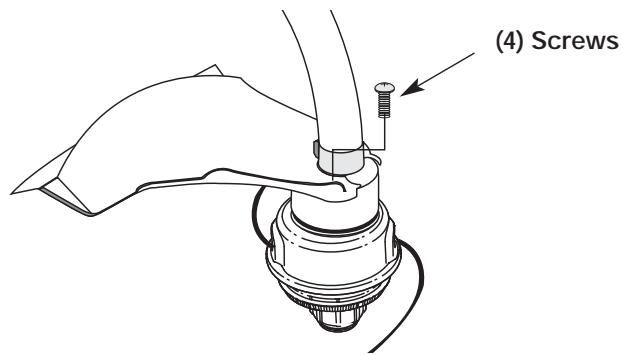
Fig. 5
- Install the screws with a Phillips screwdriver (Fig. 5).
OIL AND FUEL INFORMATION

DANGER: OVERFILLING OIL CRANKCASE MAY CAUSE SERIOUS PERSONAL INJURY. Check and maintain the proper oil level in the crank case; it is important and cannot be overemphasized. Check the oil before each use and change it as needed. See Changing the Oil.
RECOMMENDED OIL TYPE
Using the proper type and weight of oil in the crankcase is extremely important. Check the oil before each use and change the oil regularly. Failure to use the correct oil, or using dirty oil, can cause premature engine wear and failure.
Use a high-quality SAE 30 weight oil of API (American Petroleum Institute) service class SF, SG, SH.
ADDING OIL TO CRANKCASE: INITIAL USE
NOTE: This unit is shipped without oil. In order to avoid damage to the unit, put oil in the crankcase before you attempt to start the unit.
Your unit is supplied with one 3.4 fluid oz. (100 ml.) bottle of SAE 30 SF, SG, SH oil (Fig. 6).
NOTE: Save the bottle of oil. It can be used to measure the correct amount during future oil changes. See Changing the Oil.
- Unscrew the top of the bottle of oil and remove the paper seal covering the opening. Replace the top. Next, cut the tip off the funnel spout (Fig. 6).
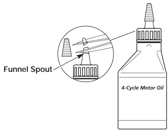
Fig. 6
- Place the unit on a flat level surface.
- Remove the oil plug / dipstick from the crankcase (Fig. 7).
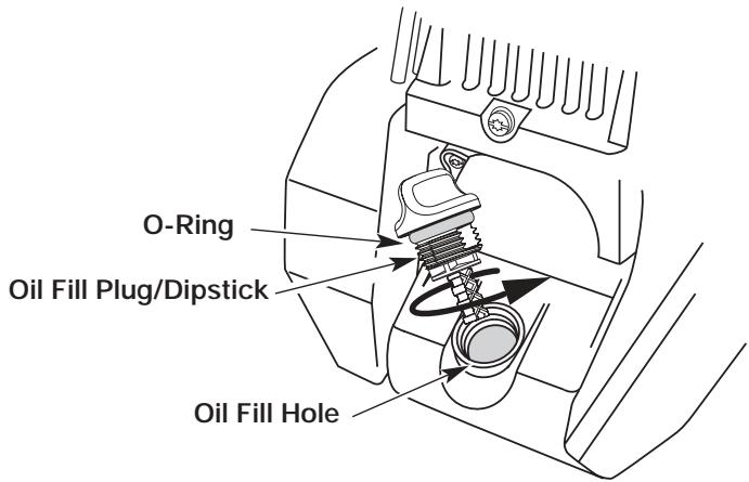
Fig. 7
- Pour the entire bottle of oil into the oil fill hole (Fig. 8).
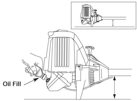
Fig. 8
NOTE: Never add oil to the fuel or fuel tank.
- Wipe up any oil that may have spilled and reinstall the oil fill plug / dipstick.
Check oil before each use and change as needed. Refer to Changing the Oil.
OIL AND FUEL INFORMATION
RECOMMENDED FUEL TYPE
Old fuel is the primary reason for improper unit performance. Be sure to use fresh, clean, unleaded gasoline.
NOTE: This is a four cycle engine. In order to avoid damage to the unit, do not mix oil with gasoline.
Definition of Blended Fuels
Today's fuels are often a blend of gasoline and oxygenates such as ethanol, methanol or MTBE (ether). Alcohol-blended fuel absorbs water. As little as 1% water in the fuel can make fuel and oil separate or form acids when stored. Use fresh fuel (less than 60 days old), when using alcohol-blended fuel.
Using Blended Fuels
If you choose to use a blended fuel, or its use is unavoidable, follow recommended precautions:
Always use fresh unleaded gasoline
- Use the fuel additive STA-BIL® or an equivalent
- Drain tank and run the engine dry before storing unit
Using Fuel Additives
The use of fuel additives, such as STA-BIL® Gas Stabilizer or an equivalent, will inhibit corrosion and minimize the formation of gum deposits. Using a fuel additive can keep fuel from forming harmful deposits in the carburetor for up to six (6) months. Add 0.8 oz. (23 ml.) of fuel additive per gallon of fuel according to the instructions on the container. NEVER add fuel additives directly to the unit's gas tank.
FUELING THE UNIT

WARNING: Gasoline is extremely flammable and its vapors can explode if ignited. To avoid serious personal injury, always stop the engine and allow it to cool before filling the fuel tank. Do not smoke while filling the tank. Keep sparks and open flames away from the area.
- Remove the fuel cap (Fig. 9).

WARNING: Remove the fuel cap slowly to avoid injury from gasoline spray.
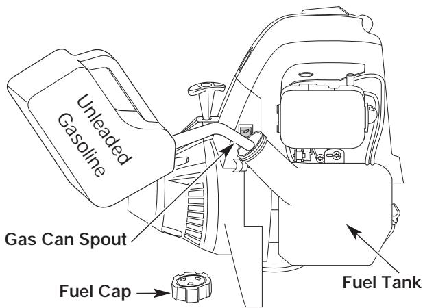
Fig. 9
- Place the gas container's spout into the fill hole on the fuel tank (Fig. 9) and fill the tank.

WARNING: Add gasoline in a clean, well-ventilated outdoor area. Avoid creating a source of ignition for spilt fuel.
NOTE: Do not overfill the tank.
- Wipe up any gasoline that may have spilled.
- Reinstall the fuel cap.

WARNING: Never operate the unit without the fuel cap securely in place.
- Move the unit at least 30 ft. (9.1 m) from the fueling source and site before starting the engine.
NOTE: Dispose of the old gasoline in accordance to Federal, State and Local regulations.
STARTING/STOPPING INSTRUCTIONS
STARTING INSTRUCTIONS

WARNING: Operate this unit only in a well-ventilated area outdoors. Carbon monoxide exhaust fumes can be lethal in a confined area.

WARNING: Avoid accidental starting. Remain in the starting position when pulling the starter rope (Fig. 12). The operator and unit must be in a stable position while starting to avoid serious personal injury.
Make sure that any Add-On item is installed correctly and secure before starting the unit.
- Check the oil level in the crankcase. Refer to Checking the Oil Level.
- Fill the fuel tank with fresh, clean unleaded gasoline. Refer to Fueling the Unit.
- Make sure the On/Off Stop Control is in the ON (I) position (Fig. 10).
NOTE: For cold weather conditions (when the temperature is below 40°F ), flip the Cold Weather Start Lever (Fig. 13) to the choked position and continue to step 4. The choked position is down and closed. DO NOT flip this lever down if the temperature is above 40°F .
- Fully press and release the primer bulb 10 times, slowly, until FUEL IS VISIBLE IN THE PRIMER BULB (Fig. 11). If you can't see fuel in the bulb, press and release the bulb as many times as it takes before you can see fuel in it.
- With the unit in the starting position (Fig. 12), DO NOT SQUEEZE THE THROTTLE CONTROL. Pull the starter rope briskly 5 times. If the engine starts to run before the fifth pull, proceed to step 6. If the engine does not start, go back to step 4.
NOTE: For cold weather conditions (when the temperature is below 40°F ), flip the Cold Weather Start Lever back to the open/up position.
6. Squeeze the throttle control to warm up the engine for 5 to 10 seconds. In cold weather, let the engine warm up for 30 to 60 seconds.
NOTE: If the engine stalls while squeezing the trigger, go back to step 5.
STOPPING INSTRUCTIONS
- Release your hand from the throttle control (Fig. 12). Allow the engine to cool down by idling.
- Put the On/Off Stop Control in the OFF (O) position (Fig. 10).
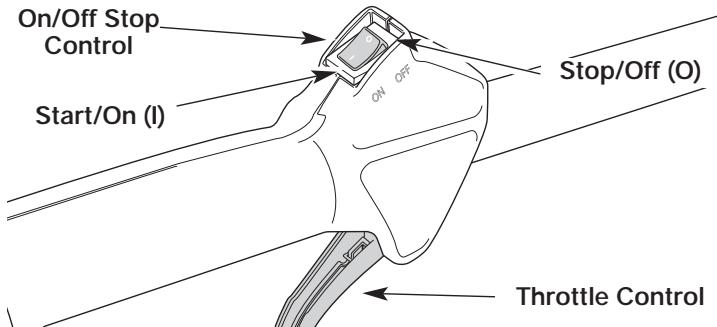
Fig. 10
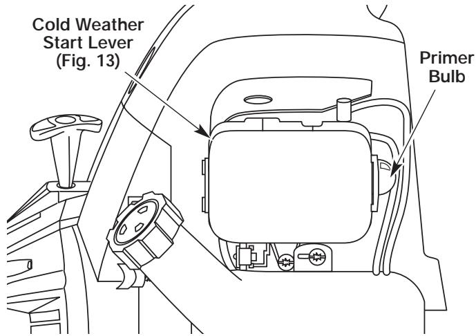
Fig. 11
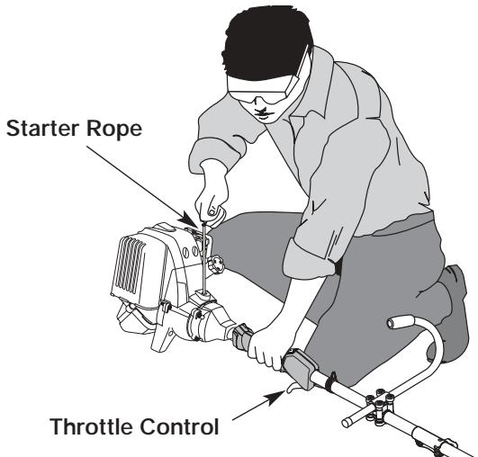
Fig. 12
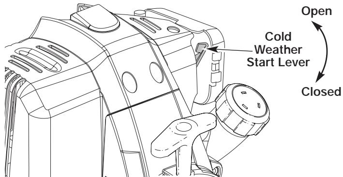
Fig. 13
OPERATING INSTRUCTIONS
WARNING: Read and understand the operator's manual for each add-on prior to operation.
Removing the Cutting Attachment or Add-Ons
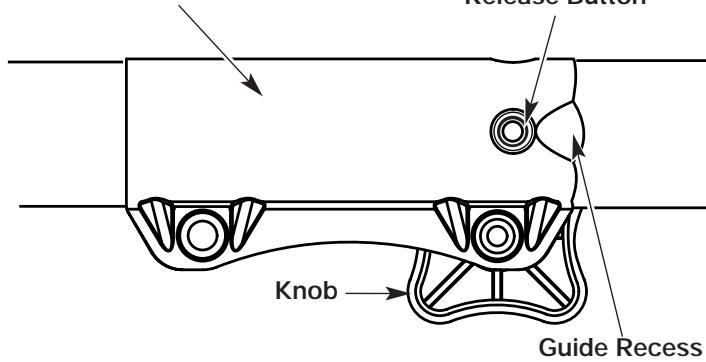
- Turn the knob counterclockwise to loosen (Fig. 14).
- Press and hold the release button (Fig. 14).
- While firmly holding the upper shaft housing, pull the cutting attachment or add-on straight out of the EZ-Link™ coupler (Fig. 15).

WARNING: To avoid serious personal injury and damage to the unit, shut unit off before removing or installing add-ons.
Installing the Cutting Attachment or Add-Ons
NOTE: To make installing or removing the add-on easier, place the unit on the ground or on a work bench.
1. Turn knob counterclockwise to loosen (Fig. 14).
EZ-Link™ Coupler
Release Button
Fig. 14
- While firmly holding the add-on, push it straight into the EZ-Link™ coupler (Fig. 15).
NOTE: Aligning the release button with the guide recess will help installation (Fig. 14).
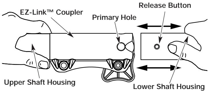
Fig. 15
- Turn the knob clockwise to tighten (Fig. 16).

CAUTION: Lock the release button in the primary hole and securely tighten the knob before operating this unit.
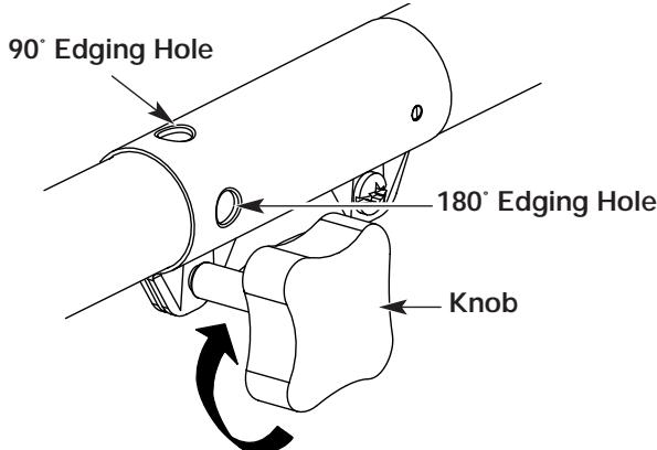
Fig. 16

CAUTION: The cutting attachment and add-ons with the EZ-Link™ system are to be used in the primary hole unless stated otherwise in the specific add-ons operator's manual. Using the wrong hole could lead to personal injury, or damage to the unit.
For edging when using the line head cutting attachment with EZ-Link™ models, lock the release button of the cutting attachment into the 90° edging hole or the 180° edging hole (Fig. 16).
OPERATING INSTRUCTIONS
HOLDING THE TRIMMER

WARNING: Always wear eye, hearing, foot and body protection to reduce the risk of injury when operating this unit.
Before operating the unit, stand in the operating position (Fig. 17). Check for the following:
- The operator is wearing eye protection and proper clothing
- With a slightly-bent right arm, the operator's hand is holding the shaft grip
- The operator's left arm is straight, the left hand holding the J-handle
The unit is at waist level - The cutting attachment is parallel to the ground and easily contacts the grass without the need to bend over
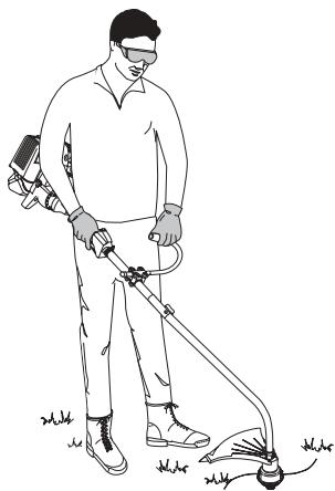
Fig. 17
ADJUSTING TRIMMING LINE LENGTH
The Bump Head™ cutting attachment allows you to release trimming line without stopping the engine. To release more line, lightly tap the cutting attachment on the ground (Fig. 18) while operating the trimmer at high speed.
NOTE: Always keep the trimming line fully extended. Line release becomes more difficult when the cutting line gets shorter.
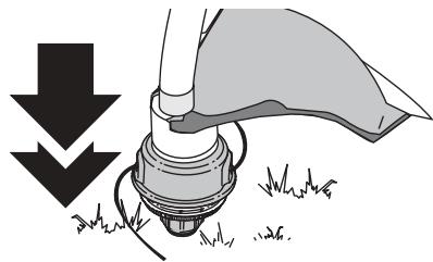
Fig. 18
Each time the head is bumped, about 1 inch (25.4 mm) of trimming line releases. A blade in the cutting attachment shield will cut the line to the proper length if any excess line is released.
For best results, tap the bump knob on bare ground or hard soil. If you attempt a line release in tall grass, the engine may stall. Always keep the trimming line fully extended. Line release becomes more difficult when the cutting line gets shorter.
NOTE: Do not rest the Bump Head™ on the ground while the unit is running.
Some line breakage will occur from:
- Entanglement with foreign matter
Normal line fatigue - Attempting to cut thick, stalky weeds
Forcing the line into objects such as walls or fence posts

CAUTION: Do not remove or alter the line cutting blade assembly. Excessive line length will make the clutch overheat. This may lead to serious personal injury or damage to the unit.
TIPS FOR BEST TRIMMING RESULTS
- Keep the cutting attachment parallel to the ground.
- Do not force the cutting attachment. Allow the tip of the line to do the cutting, especially along walls. Cutting with more than the tip will reduce cutting efficiency and may overload the engine.
- Cut grass over 8 inches (200 mm) by working from top to bottom in small increments to avoid premature line wear or engine drag.
- Cut from right to left whenever possible. Cutting to the left improves the unit's cutting efficiency. Clippings are thrown away from the operator.
- Slowly move the trimmer into and out of the cutting area at the desired height. Move either in a forward-backward or side-to-side motion. Cutting shorter lengths produces the best results.
- Trim only when grass and weeds are dry.
- The life of your cutting line is dependent upon:
Following the trimming techniques
What vegetation is being cut
Where vegetation is cut
For example, the line will wear faster when trimming against a foundation wall as opposed to trimming around a tree.
DECORATIVE TRIMMING
- Decorative trimming is accomplished by removing all vegetation around trees, posts, fences and more.
- Rotate the whole unit so that the cutting attachment is at a 30° angle to the ground (Fig. 19).
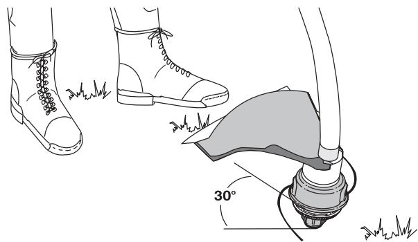
Fig. 19
MAINTENANCE AND REPAIR INSTRUCTIONS
MAINTENANCE SCHEDULE
Perform these required maintenance procedures at the frequency stated in the table. These procedures should also be a part of any seasonal tune-up.
NOTE: Some maintenance procedures may require special tools or skills. If you are unsure about these procedures take your unit to any non-road engine repair establishment, individual or authorized service dealer.
NOTE: Maintenance, replacement, or repair of the emission control devices and system may be performed by any non-road engine repair establishment, individual or authorized service dealer.

WARNING: To prevent serious injury, never perform maintenance or repairs with the unit running. Always service and repair a cool unit. Disconnect the spark plug wire to ensure that the unit cannot start.
| FREQUENCY | MAINTENANCE REQUIRED | REFER TO |
| Before starting engine | Fill fuel tank with fresh fuel Check oil | Page 9 Page 16 |
| Every 10 hours | Clean and re-oil air filter | Page 17 |
| First change at 10 hours Every 25 hours thereafter Every 25 hours | Change oil Change oil Clean spark arrestor | Page 16 Page 16 Page 20 |
| 10 hours on new engine Every 25 hours Every 25 hours | Check rocker arm to valve clearance and adjust Check rocker arm to valve clearance and adjust Check spark plug condition and gap | Page 18 Page 18 Page 20 |
LINE INSTALLATION FOR THE SPEEDSPOOL®

WARNING: Never use metal-reinforced line, wire, chain, or rope, etc. These can break off and become dangerous projectiles.
Always use Genuine Factory Parts™ 0.095 inch (2.41 mm) replacement line. Lines other than those specified may make the engine overheat or fail.
There are two methods to replace the SpeedSpool® trimming line:
- Wind the inner reel with new line
Install a pre-wound inner reel
Winding the Inner Reel With New Line
NOTE: It Is unnecessary to remove the bump knob to install a new trimming line.
- Cut two pieces of 0.095 inch (2.41 mm) trimming line, 10 feet (3 m) long.
- Hold the outer spool and turn the inner reel counterclockwise to line up the arrows on the outer spool and inner reel (Fig. 20).

WARNING: Always use the correct line length when installing trimming line on the unit. The line may not release properly if the line is too long.
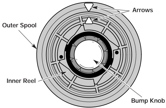
Top View Of The SpeedSpool®
Fig. 20
MAINTENANCE AND REPAIR INSTRUCTIONS
- Pull old line out of the line loading and line locking holes (Fig. 21 and 22).
- Insert a piece of trimming line into one of the two eyelets in the outer spool. Push it up through the line loading hole in the inner reel (Fig. 21). Do not bend the line when inserting it into the eyelet.
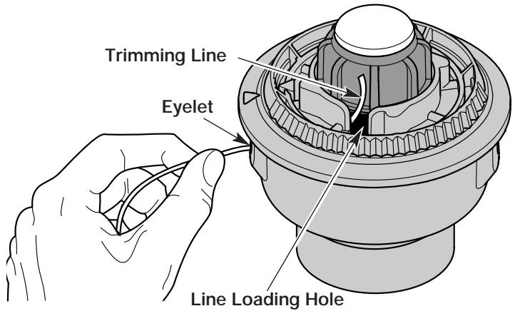
Fig. 21
- Insert the line into the locking hole (Fig. 22). Do not push the line more than a 1/2 inch (12.7 mm) into the line locking hole. The line will form a small loop (Fig. 22) when it is inserted correctly.
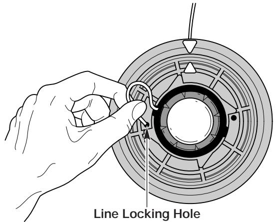
Fig. 22
- Pull the line from the outer spool until the line is tight against the inner reel (Fig. 23).
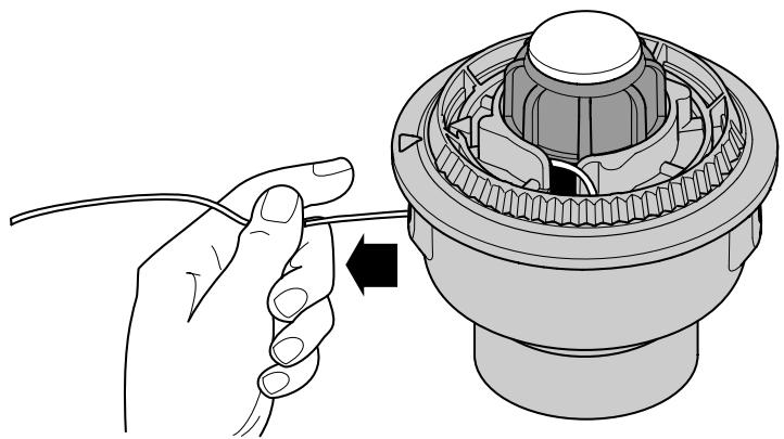
Fig. 23
- Repeat procedures 4-6 with the second piece of line.
- Hold the outer spool. Wind the inner reel counterclockwise until approximately four (4) inches (102 mm) of line remain (Fig. 24).
NOTE: Do not wind the inner reel before installing the second piece of line.
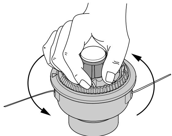
Fig. 24
- If winding the line becomes difficult or if the line jams, pull the ends of the line from the spool (Fig. 25). Continue winding the inner reel counterclockwise.
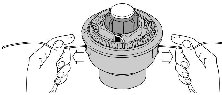
Fig. 25
INSTALLING A PRE-WOUND REEL
- Turn the bump knob counterclockwise and remove the bump knob, spring and foam seal (Fig. 26).
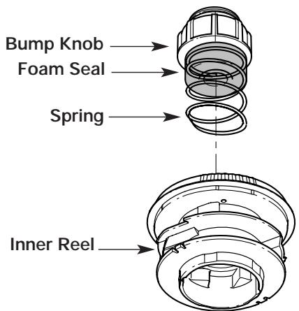
Fig. 26
MAINTENANCE AND REPAIR INSTRUCTIONS
- Pull the old inner reel with existing line from the outer spool.
- Insert the ends of the prewound inner reel line into the outer spool eyelets (Fig. 27). Push the new inner reel, arrow side up, into the outer spool.
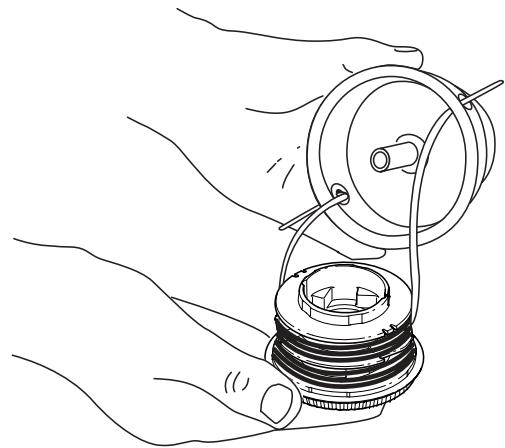
Fig. 27
- Hold the inner reel in place and install the bump knob, spring and foam seal. Press down and turn the bump knob clockwise. Grasp the ends and pull firmly to release the line from the holding slots in the inner reel (Fig. 25).
Releasing the Inner Reel
If the SpeedSpool® does not release line correctly, pull the ends of the line firmly from the spool (Fig. 25). If this does not the release line, follow the Cleaning the SpeedSpool® instructions.
CLEANING THE SPEEDSPOOL
Cleaning the SpeedSpool® may be necessary if:
- A jammed or excessive line must be removed
- The SpeedSpool® becomes difficult to wind or does not operate correctly when bumping the head on the ground
- Hold the outer spool, and unscrew the bump knob counterclockwise (Fig. 28).
- Pull out the bump knob, spring and foam seal (Fig. 26).
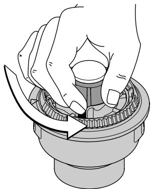
Fig. 28
-
Pull the inner reel with existing line from the outer spool.
-
Remove any existing line from the inner reel before cleaning. Remove any debris or grass from the knob, spring, inner reel and foam seal. Wash the inner reel with warm soapy water (Fig. 29).
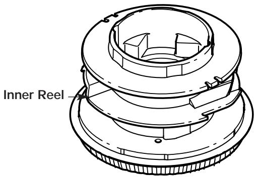
Fig. 29
- Clean the shaft and the inner surface of the outer spool. To clean the shaft underneath the plunger, press down on the plunger (Fig. 30). Remove any dirt or debris from the shaft.
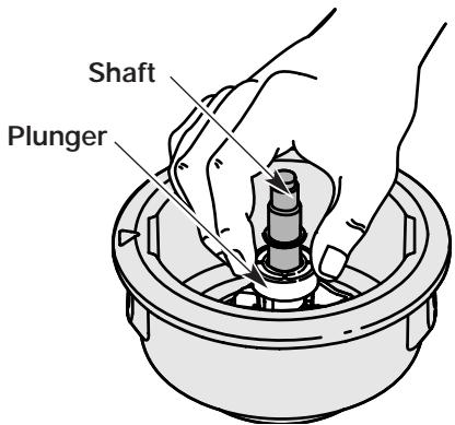
Fig. 30
NOTE: The inner reel must be totally dry before reinstalling it into the outer spool. Do not lubricate the inner reel or outer spool assembly.
- Place the inner reel into the outer spool.
- Place the bump knob, spring and foam seal onto the inner reel (Fig. 26).
- Press the bump knob down and tighten clockwise.
- Install new line as described in Line Installation for the SpeedSpool®.
SPEEDSPOOL® REPLACEMENT PARTS
Replacement Line 180120
Replacement Line Cartridge 753-04218
Inner Reel Spring 181465
Foam Seal 181467
Inner Reel 181464
Bump Head™ Assembly 181468
(Bump Knob, Foam Seal, Spring,)
These SpeedSpool® replacement parts can be purchased from your local authorized dealer.
MAINTENANCE AND REPAIR INSTRUCTIONS
CHECKING THE OIL LEVEL

CAUTION: To prevent extensive engine wear and damage to the unit, always maintain the proper oil level in the crankcase. Never operate the unit with the oil level below the bottom of the dipstick.
The importance of checking and maintaining the proper oil level in the crankcase cannot be overemphasized. Check oil before each use:
- Stop the engine and allow oil to drain into the crankcase.
- Place the unit on a flat, level surface to get a proper oil level reading.
- Keep dirt, grass clippings and other debris out of the engine. Clean the area around the oil fill plug/dipstick before removing it.
- Remove the oil fill plug/dipstick and wipe off oil. Reinsert it all the way back in.
- Remove the oil fill plug/dipstick and check the oil level. Oil should be up to the top of the dipstick (Fig. 31).
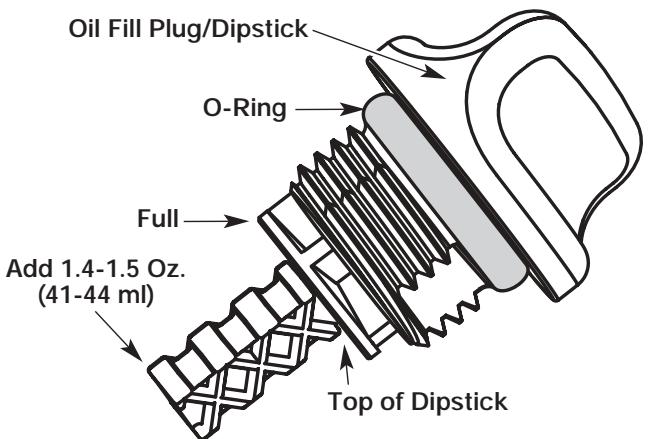
Fig. 31
- If the level is low, add a small amount of oil to the oil fill hole and recheck (Fig. 32). Repeat this procedure until the oil level reaches the top of the dipstick.
NOTE: Do not overfill the unit.
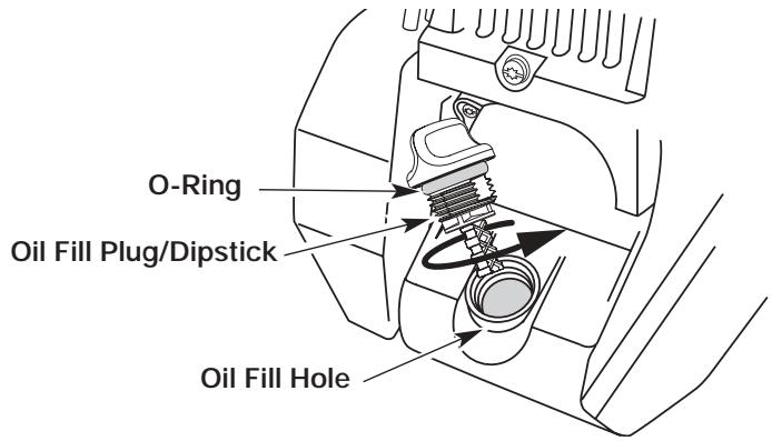
Fig. 32
NOTE: Make sure the O-ring is in place on the oil fill plug/dipstick when checking and changing the oil (Fig. 32).
CHANGING THE OIL
For a new engine, change the oil after the first 10 hours of operation. Change the oil while the engine is still warm. The oil will flow freely and carry away more impurities.

CAUTION: Wear gloves to prevent injury when handling the unit.
- Unplug spark plug boot to prevent accidental starting.
- Remove the oil fill plug/dipstick.
- Pour the oil out of the oil fill hole and into a container by tipping the unit to a vertical position (Fig. 33). Allow ample time for complete drainage.
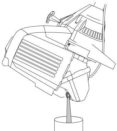
Fig. 33
- Wipe up any oil residue on the unit and clean up any oil that may have spilled. Dispose of the oil according to Federal, State and local regulations.
- Refill the crankcase with 3.4 fluid ounce (100 ml) of SAE 30 SF, SG, SH oil.
NOTE: Use the bottle and spout saved from initial use to measure the correct amount of oil. The top of the label on the bottle measures approximately 3.4 ounces (100 ml) (Fig. 34). Check the level with the dipstick. If the level is low, add a small amount of oil and recheck. Do not overfill (Fig. 34).
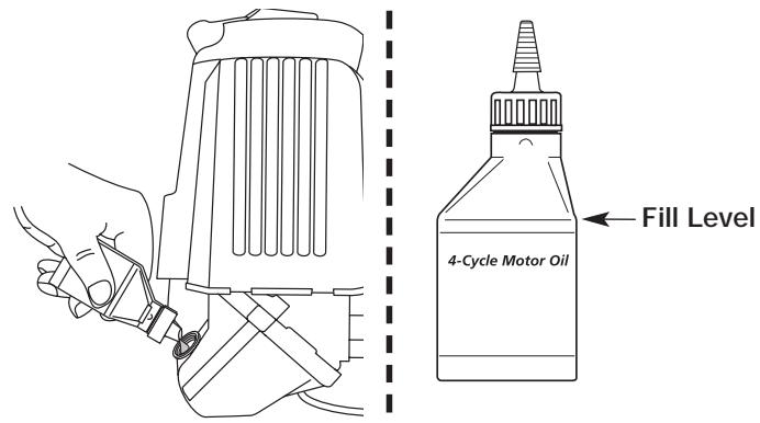
Fig. 34
- Replace the oil fill plug/dipstick.
- Reconnect the spark plug boot.
MAINTENANCE AND REPAIR INSTRUCTIONS
AIR FILTER MAINTENANCE
Cleaning the Air Filter
Clean and re-oil the air filter every 10 hours of operation. It is an important item to maintain. Failure to maintain the air filter will Void the warranty.

WARNING: To avoid serious personal injury, always turn your trimmer off and allow it to cool before you clean or service it.
- Open the air filter cover. Push the tab on the right side of the cover inward. Then pull the air filter cover out and to the left (Fig. 35).
NOTE: It may be necessary to remove the fuel cap to completely remove the air filter cover. - Remove the air filter (Fig. 35).
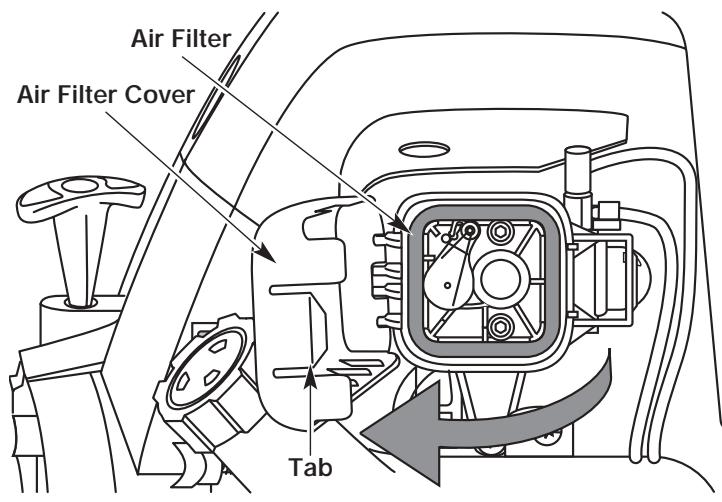
Fig. 35
- Wash the filter in detergent and water (Fig. 36). Rinse the filter thoroughly and allow it to dry.
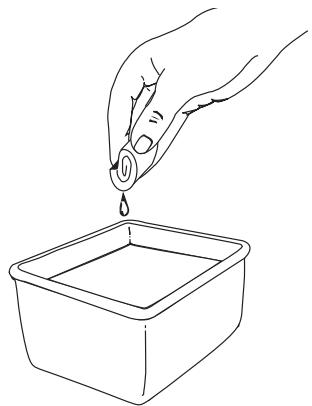
Fig. 36
- Apply enough clean SAE 30 motor oil to lightly coat the filter (Fig. 37).
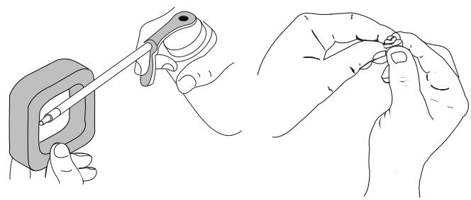
Fig. 37
Fig. 38
- Squeeze the filter to spread and remove excess oil (Fig. 38).
- Replace the filter (Fig. 39).
NOTE: If the unit is operated without the air filter, you will Void the warranty.
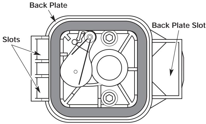
Fig. 39
- Reinstall the air filter cover. Position the hooks on the left side of the air filter cover into the slots at the left side of the back plate (Fig. 39).
NOTE: It may be necessary to remove the fuel cap to reinstall the air filter cover. - Swing the cover to the right until the tab on the air filter cover snaps into place in the slot on the back plate (Fig. 39).
- Replace the fuel cap if it was removed.
CARBURETOR ADJUSTMENT
The idle speed of the engine is adjustable. An idle adjustment screw is reached though a hole in the top of the engine cover (Fig. 40).
NOTE: Careless adjustments can seriously damage your unit. An authorized service dealer should make carburetor adjustments.
Check Fuel
Old fuel is usually the reason for improper unit performance. Drain and refill the tank with fresh fuel prior to making any adjustments. Refer to Oil and Fuel Information.
MAINTENANCE AND REPAIR INSTRUCTIONS
Clean Air Filter
The condition of the air filter is important to the operation of the unit. A dirty air filter will restrict air flow. This is often mistaken for an out of adjustment carburetor. Check the condition of the air filter before adjusting the idle speed screw. Refer to Air Filter Maintenance.
Adjust Idle Speed Screw

WARNING: The cutting attachment may spin during idle speed adjustments. Wear protective clothing and observe all safety instructions to prevent serious personal injury.
If, after checking the fuel and cleaning the air filter, the engine still will not idle, adjust the idle speed screw as follows:
- Start the engine and let it run at a high idle for a minute to warm up. Refer to Starting/Stopping Instructions.
- Release the throttle trigger and let the engine idle. If the engine stops, insert a small phillips or flat blade screwdriver into the hole in the air filter/muffler cover (Fig. 40). Turn the idle speed screw in, clockwise, 1/8 of a turn at a time (as needed) until the engine idles smoothly.
NOTE: The cutting attachment should not rotate when the engine idles.
- If the cutting attachment rotates when the engine idles, turn the idle speed screw counterclockwise 1/8 of a turn at a time (as needed), to reduce idle speed.
Checking the fuel, cleaning the air filter, and adjusting the idle speed should solve most engine problems. If not and all of the following are true:
- the engine will not idle
- the engine hesitates or stalls on acceleration
- there is a loss of engine power
Have the carburetor adjusted by an authorized service dealer.

WARNING: To prevent serious personal injury, make sure the cutting attachment has stopped rotating before you turn it off and set it down.
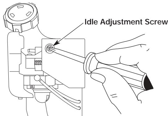
Fig. 40
This requires disassembly of the engine. If you feel unsure or unqualified to perform this, take the unit to an authorized service center.
NOTE: Inspect the valve to rocker arm clearance with a feeler gauge after the first 10 hours of operation and then every 25 hours of operation thereafter.
- The engine must be cold when checking or adjusting the valve clearance.
-
This task should be performed inside, in a clean, dust free area.
-
Remove the muffler cover by pressing down on it, separating it from the engine cover. Using a flat blade screwdriver, disengage the middle and front tabs and slots first. The cover will hinge off from the rear tab (Fig. 41).
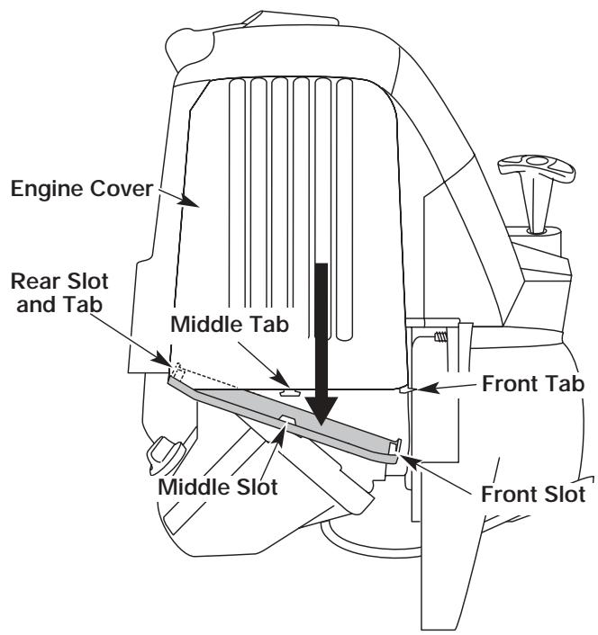
Fig. 41
- Remove the two (2) screws on top of the engine cover with a Flat-head or T-20 Torx screwdriver (Fig. 42).
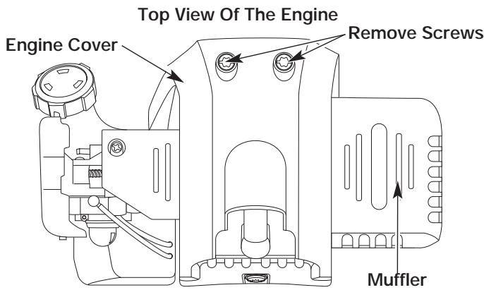
Fig. 42
MAINTENANCE AND REPAIR INSTRUCTIONS
- Remove the screw behind the engine cover (Fig. 43).
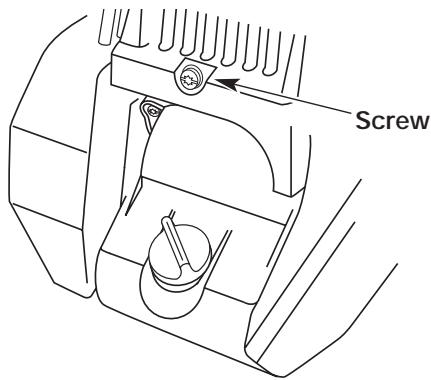
Fig. 43
- Disconnect the spark plug wire.
- Clean dirt from around the spark plug. Remove the spark plug from the cylinder head by turning a 5/8 in. socket counterclockwise.
- Remove the engine cover (Fig. 42).
- Clean dirt from around the rocker arm cover. Remove the screw holding the rocker arm cover with a large flat blade screwdriver or Torx T-25 bit (Fig. 44). Remove the rocker arm cover and gasket.
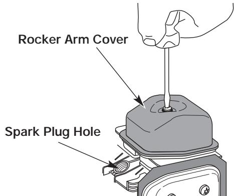
Fig. 44
-
Pull the starter rope slowly to bring the piston to the top of its travel, (known as top dead center). Check that:
-
The piston is at the top of its travel while looking in the spark plug hole (Fig. 44)
- Both rocker arms move freely, and both valves are closed
If these statements are not true, repeat this step.
- Slide the feeler gauge between the rocker arm and the valve return spring. Measure the clearance between the valve stem and rocker arm (Fig. 45). Measure both the intake and exhaust valves.
The recommended clearance for the intake is .003 - .006 in. (.076 - 0.152 mm). The recommended clearance for the exhaust is .013 - .016 in. (.330 - 0.406 mm).
Use a standard automotive .005 in. (0.127 mm) feeler gauge. The feeler gauge should slide between the rocker arm and valve stem with a slight amount of resistance, without binding. Figure 45 shows how to measure the intake clearance, while Figure 46 shows the exhaust clearance.
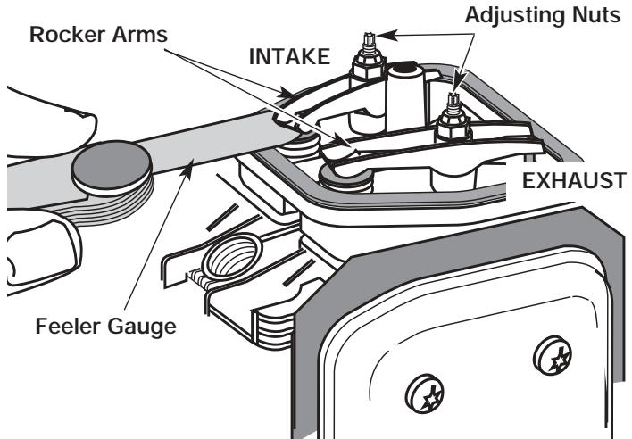
Fig. 45
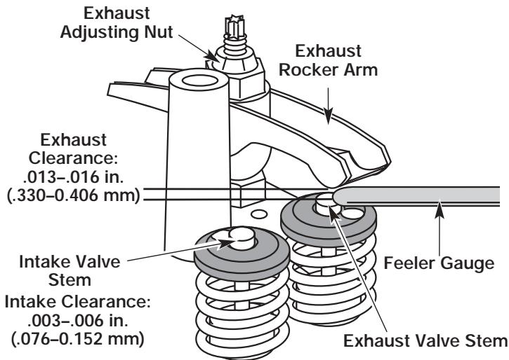
Fig. 46
- If the clearance is not within specification:
a. Turn the adjusting nut using a 5/16 inch (8 mm) wrench or nut driver (Fig. 46).
- To increase clearance, turn the adjusting nut counterclockwise.
- To decrease clearance, turn the adjusting nut clockwise.
b. Recheck both clearances, and adjust as necessary.
- Reinstall the rocker arm cover using a new gasket. Torque the screw to 20-30 in·lb (2.2-3.4 N·m).
-
Reinstall the engine cover. Check alignment of the cover before tightening the screws. Tighten screws.
-
Reinstall the muffler cover. Slip the rear tab on the muffler cover into the engine cover rear slot. Then slide the remaining slots into the tabs until they snap into place (Fig. 41).
-
Check the spark plug and reinstall. See Replacing the Spark Plug.
- Replace the spark plug wire.
MAINTENANCE AND REPAIR INSTRUCTIONS
REPLACING THE SPARK PLUG
Use only Champion RDZ19H spark plug or equivalent. The correct air gap is 0.025 in. (0.655 mm.). Remove the plug after every 25 hours of operation and check its condition.
- Stop the engine and allow it to cool. Grasp the plug wire firmly and pull the cap from the spark plug.
- Clean dirt from around the spark plug. Remove the spark plug from the cylinder head by turning a 5/8 in. socket counterclockwise.
- Replace cracked, fouled or dirty spark plug. Set the air gap at 0.025 in. (0.655 mm.) using a feeler gauge (Fig. 47).
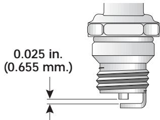
Fig. 47

CAUTION: Do not sand blast, scrape, or clean electrodes. Grit in the engine could damage the cylinder.
- Install a correctly-gapped spark plug in the cylinder head. Turn the 5/8 in. socket clockwise until snug.
If using a torque wrench torque to:
110-120 in. lb. (12.3-13.5 N·m)
Do not over tighten.
SPARK ARRESTOR MAINTENANCE
- Remove the muffler cover. See Rocker Arm Clearance.
- With a flat blade screwdriver or Torx T-20 bit, remove the screw attaching the spark arrester cover to the muffler (Fig. 48).
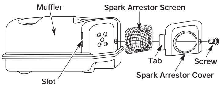
Fig. 48
- Pull the tab on the spark arrestor cover out of the muffler. Remove the spark arrestor cover.
- Remove the spark arrestor screen from the spark arrestor cover.
- Clean the spark arrestor screen with a wire brush or replace it.
- Reinstall the spark arrestor screen, spark arrestor cover and screw.
MAINTENANCE AND REPAIR INSTRUCTIONS
CLEANING

WARNING: To avoid serious personal injury, always turn your trimmer off and allow it to cool before you clean or do any maintenance on it.
Use a small brush to clean off the outside of the unit. Do not use strong detergents. Household cleaners that contain aromatic oils such as pine and lemon, and solvents such as kerosene, can damage plastic housing or handle. Wipe off any moisture with a soft cloth.
STORAGE
- Never store the unit with fuel in the tank where fumes may reach an open flame or spark.
- Allow the engine to cool before storing.
- Lock up the unit to prevent unauthorized use or damage.
- Store the unit in a dry, well-ventilated area.
- Store the unit out of the reach of children.
LONG TERM STORAGE
- Drain all gasoline from the gas tank into a container. Do not use gas that has been stored for more than 60 days. Dispose of the old gasoline in accordance to Federal, State, and Local regulations.
- Start the engine and allow it to run until it stalls. This ensures that all gasoline has been drained from the carburetor.
- Allow the engine to cool. Remove the spark plug and put 1 oz. (30 ml) of high quality motor oil into the cylinder. Pull the starter rope slowly to distribute the oil. Reinstall the spark plug.
NOTE: Remove the spark plug and drain all of the oil from the cylinder before attempting to start the trimmer after storage.
- Change the oil, referring to Changing the Oil. Dispose of the old oil in accordance to Federal, State and Local regulations.
- Thoroughly clean the unit and inspect for any loose or damaged parts. Repair or replace damaged parts and tighten loose screws, nuts or bolts. The unit is ready for storage.
TRANSPORTING
- Allow the engine to cool before transporting.
- Secure the unit while transporting.
- Drain the gas tank before transporting.
- Tighten gas cap before transporting.
ACCESSORIES/REPLACEMENT PARTS
4-Cycle Oil 181786
Spark Plug 180852
Spark Arrestor Screen 180890
Replacement Line Cartridge . 753-04218
Fuel Cap .753-1229
Shoulder Harness 682075
For a full list of replacement parts, refer to the parts list located at the inside back cover of this manual.
TROUBLESHOOTING
ENGINE WILL NOT START
CAUSE
Empty fuel tank
Primer bulb wasn't pressed enough.
Old fuel
Fouled spark plug
Plugged spark arrestor
When it is above 40°F outside, the Cold Weather Start
Lever is in the CLOSED/DOWN position
When it is below 40°F outside, the Cold Weather Start Lever
is in the OPEN/UP position
ACTION
Fill fuel tank with new fuel
Press primer bulb fully and slowly 10 times
Drain gas tank and add fresh fuel
Replace or clean the spark plug
Clean or replace spark arrestor
Flip the Cold Weather Start Lever to OPEN/UP
Flip the Cold Weather Start Lever to CLOSED/DOWN
and follow the Starting Instructions
ENGINE WILL NOT IDLE
CAUSE
Air filter is plugged
Old fuel
Improper carburetor adjustment
ACTION
Replace or clean the air filter
Drain gas tank and add fresh fuel
Adjust carburetor
ENGINE WILL NOT ACCELERATE
CAUSE
Old fuel
Improper carburetor adjustment
Cutting attachment bound with grass
Dirty air filter
Plugged spark arrestor
ACTION
Drain gas tank and add fresh fuel
Take to an authorized service dealer for adjustment
Stop the engine and clean the cutting attachment
Clean or replace the air filter
Clean or replace spark arrestor
ENGINE LACKS POWER OR STALLS WHEN CUTTING
CAUSE
Old fuel
Improper carburetor adjustment
Fouled spark plug
Plugged spark arrestor
ACTION
Drain gas tank and add fresh fuel
Take to an authorized service dealer for adjustment
Replace or clean the spark plug
Clean or replace spark arrestor
CUTTING ATTACHMENT WILL NOT ADVANCE LINE
CAUSE
Cutting attachment bound with grass
Cutting attachment out of line
Inner reel bound up
Cutting head dirty
Line welded
Line twisted when refilled
Not enough line is exposed
ACTION
Stop the engine and clean cutting attachment
Refill with new line
Replace the inner reel
Clean inner reel and outer spool
Disassemble, remove the welded section and rewind
Disassemble and rewind the line
Push the bump knob and pull out line until 4 inches
(102 mm) of line is outside of the cutting attachment
CUTTING LINE ADVANCES UNCONTROLLABLY
CAUSE
Oil, cleaner or lubricant in cutting head
ACTION
Clean and thoroughly dry the cutting head
If further assistance is required, contact your authorized service dealer.
SPECIFICATIONS
ENGINE*
| Engine Type | Air-Cooled, 4-Cycle |
| Displacement | 1.6 cu. in. (26.2 cc) |
| Clutch Type | Centrifugal |
| Operating RPM | 6,800 - 9,300 rpm |
| Idle Speed RPM | 3,000 - 3,600 rpm |
| Ignition Type | Electronic |
| Ignition Switch | Rocker Switch |
| Valve clearance (intake) | .003-.006 in. (.076-.152 mm) |
| Valve clearance (exhaust) | .013-.016 in. (.330-.406 mm) |
| Spark Plug Gap | 0.025 inch (0.655 mm) |
| Lubrication | SAE 30 Oil |
| Crankcase Oil Capacity | 3.4 oz (100 ml) |
| Fuel | Unleaded |
| Carburetor | Diaphragm, All-Position |
| Starter | Auto Rewind |
| Muffler | Baffled with Guard |
| Throttle | Manual Spring Return |
| Fuel Tank Capacity | 12 oz (355 ml) |
DRIVE SHAFT & CUTTING ATTACHMENT*
| Drive Shaft Housing | Aluminum Tube (EZ-Link™) |
| Throttle Control | Finger-Tip Trigger |
| Unit Weight (No Fuel, with J-handle, Cutting attachment shield and Cutting attachment) | 13.15 lbs (6 kg) |
| Cutting Mechanism | Dual String Cutting Head |
| Line Spool | Bump Line Releaser |
| Line Spool Diameter | 3 inches (76.2 mm) |
| Trimming Line Diameter | 0.095 inches (2.41 mm) |
| Cutting Path Diameter | 17 inches (43.18 cm) |
*All specifications are based on the latest product information available at the time of printing. We reserve the right to make changes at any time without notice.
NOTES
EPA Emission Control Warranty Statement
Your Warranty Rights and Obligations
The Environmental Protection Agency and MTD SOUTHWEST INC (MTD) are pleased to explain the emission control system warranty on your 2002 and later small off-road engine. New small off-road engines must be designed, built and equipped to meet stringent anti-smog standards. MTD must warrant the emission control system on your small off-road engine for the periods of time listed below provided there has been no abuse, neglect or improper maintenance of your small off-road engine.
Your emission control system may include parts such as the carburetor or fuel-injected system, the ignition system, and catalytic converter. Also included may be hoses, belts, connectors and other emission-related assemblies.
Where a warrantable condition exists, MTD will repair your small off-road engine at no cost to you including diagnosis, parts and labor.
The 2002 and later small off-road engines are warranted for two years. If any emission-related part on your engine is defective, the part will be repaired or replaced my MTD.
Owners Warranty Responsibilities
- As the small off-road engine owner, you are responsible for the performance of the required maintenance listed in your operator's manual. MTD recommends that you retain all receipts covering maintenance on your small off-road engine, but MTD cannot deny warranty solely for the lack of receipts or for your failure to ensure the performance of all scheduled maintenance.
- As the small off-road engine owner, you however should be aware that MTD may deny you warranty coverage if your small off-road engine or a part has failed due to abuse, neglect, improper maintenance or unapproved modifications.
- You are responsible for presenting your small off-road engine to a MTD Authorized Service Center as soon as a problem exists. The warranty repairs should be completed in a reasonable amount of time, not to exceed 30 days.
If you have any questions regarding your warranty rights and responsibilities, you should call 1-800-345-8746.
Manufacturer's Warranty Coverage
- The warranty period begins on the date the engine or equipment is delivered to the retail purchaser.
- The manufacturer warrants to the initial owner and each subsequent purchaser, that the engine is free from defects in material and workmanship which cause the failure of a warranted part for a period of two years.
- Repair or replacement of warranted part will be performed at no charge to the owner at an Authorized MTD Service Center. For the nearest location please contact MTD at: 1-800-345-8746.
- Any warranted part which is not scheduled for replacement, as required maintenance or which is scheduled for only for regular inspection to the effect of "Repair or Replace as Necessary" is warranted for the warranty period. Any warranted part which is scheduled for replacement as required maintenance will be warranted for the period of time up to the first scheduled replacement point for that part.
- The owner will not be charged for diagnostic labor which leads to the determination that a warranted part is defective, if the diagnostic work is performed at an Authorized MTD Service Center.
- The manufacturer is liable for damages to other engine components caused by the failure of a warranted part still under warranty.
- Failures caused by abuse, neglect or improper maintenance are not covered under warranty.
- The use of add-on or modified parts can be grounds for disallowing a warranty claim. The manufacturer is not liable to cover failures of warranted parts caused by the use of add-on or modified parts.
- In order to file a claim, go to your nearest Authorized MTD Service Center. Warranty services or repairs will be provided at all Authorized MTD Service Centers.
- Any manufacturer approved replacement part may be used in the performance of any warranty maintenance or repair of emission related parts and will be provided without charge to the owner. Any replacement part that is equivalent in performance or durability may be used in non-warranty maintenance or repair and will not reduce the warranty obligations of the manufacturer
- The following components are included in the emission related warranty of the engine, air filter, carburetor, primer, fuel lines, fuel pick up/ fuel filter, ignition module, spark plug and muffler.
MANUFACTURER'S LIMITED WARRANTY FOR:
TROY-BILT®
The limited warranty set forth below is given by Troy-Bilt LLC with respect to new merchandise purchased and used in the United States, its possessions and territories.
Troy-Bilt LLC warrants this product against defects in material and workmanship for a period of two (2) years commencing on the date of original purchase and will, at its option, repair or replace, free of charge, any part found to be defective in material or workmanship. This limited warranty shall only apply if this product has been operated and maintained in accordance with the Operator's Manual furnished with the product, and has not been subject to misuse, abuse, commercial use, neglect, accident, improper maintenance, alteration, vandalism, theft, fire, water or damage because of other peril or natural disaster. Damage resulting from the installation or use of any accessory or attachment not approved by Troy-Bilt LLC for use with the product(s) covered by this manual will void your warranty as to any resulting damage. This warranty is limited to ninety (90) days from the date of original retail purchase for any Troy-Bilt product that is used for rental or commercial purposes, or any other income-producing purpose.
HOW TO OBTAIN SERVICE: Warranty service is available, WITH PROOF OF PURCHASE THROUGH YOUR LOCAL AUTHORIZED SERVICE DEALER. To locate the dealer in your area, visit our website at www.troybilt.com, check for a listing in the Yellow Pages, call 1 (866) 840-6483 or 1 (330) 558-7220 or write to TroyBilt LLC, PO Box 361131, Cleveland, OH 44136-0019.
This limited warranty does not provide coverage in the following cases:
A. Tune-ups - Spark Plugs, Carburetor Adjustments, Filters
B. Wear items - Bump Knobs, Outer Spools, Cutting Line, Inner Reels, Starter Pulley, Starter Ropes, Drive Belts
C. Troy-Bilt LLC does not extend any warranty for products sold or exported outside of the United States of America, its possessions and territories, except those sold through Troy-Bilt's authorized channels of export distribution.
Troy-Bilt LLC reserves the right to change or improve the design of any Troy-Bilt Product without assuming any obligation to modify any product previously manufactured.
No implied warranty, including any implied warranty of merchantability or fitness for a particular purpose, applies after the applicable period of express written warranty above as to the parts as identified. No other express warranty or guaranty, whether written or oral, except as mentioned above, given by any person or entity, including a dealer or retailer, with respect to any product shall bind Troy-Bilt LLC During the period of the Warranty, the exclusive remedy is repair or replacement of the product as set forth above. (Some states do not allow limitations on how long an implied warranty lasts, so the above limitation may not apply to you.)
The provisions as set forth in this Warranty provide the sole and exclusive remedy arising from the sales. Troy-Bilt LLC shall not be liable for incidental or consequential loss or damages including, without limitation, expenses incurred for substitute or replacement lawn care services, for transportation or for related expenses, or for rental expenses to temporarily replace a warranted product. (Some states do not allow limitations on how long an implied warranty lasts, so the above limitation may not apply to you.)
In no event shall recovery of any kind be greater than the amount of the purchase price of the product sold. Alteration of the safety features of the product shall void this Warranty. You assume the risk and liability for loss, damage, or injury to you and your property and/or to others and their property arising out of the use or misuse or inability to use the product.
This limited warranty shall not extend to anyone other than the original purchaser, original lessee or the person for whom it was purchased as a gift.
How State Law Relates to this Warranty: This warranty gives you specific legal rights, and you may also have other rights which vary from state to state.
To locate your nearest service dealer dial 1 (866) 840-6483.
Troy-Bilt LLC
PO Box 361131
Cleveland, OH 44136-0019
INSTRUCTIONS D'ARRÉT
Item Part No. Description
1 753-04083 Engine Cover
2 791-182339 Engine Cover Screws
3 791-181025 Valve Cover Screw
4 791-182098 Valve Cover
5 791-182099 Valve Cover Gasket
6 791-182340 Rocker Adjustment Nut
7 791-182101 Rocker Arm Pivot
8 791-182100 Rocker Arm
9 791-182341 Rocker Arm Stud
10 791-182103 Valve Spring Retainer
791-181038 Valve Spring
12 791-182102 Push Rod Guide
13 791-181033 Push Rod
791-182745 Cylinder Assembly (includes 9 & 12)
791-182344 Cylinder Screw
791-182347 Carburetor Mount (includes 18)
20 791-182348 Carburetor Mount Screw
21 791-182732 Carburetor Gasket
22 753-04296 Carburetor with Primer
23 791-181751 O-Ring, Carburetor
24 753-04305 Air Filter/Choke Cover Assembly (includes 27)
25 791-182097 Breather Tube
26 791-181750 Air Filter Mounting Screw
27 791-181757 Air Filter
28 753-1229 Fuel Cap
29 791-182352 Fuel Return Line
30 791-182353 Fuel Pick-Up Line with Filter
32 791-181080 Screw
32 791-182354 Washer
33 753-1230 Fuel Tank Assembly (includes 28-30)
34 791-182356 Fuel Tank Shield
35 753-04297 Throttle C
36 791-182358 Muffler Baffle
37 791-181048 Muffler Gasket
791-182359 Muffler (includes 37, 39-41)
39 791-180890 Spark Arrestor Screen
40 791-181045 Screen Cover
41 791-181046 Screw
42 791-182361 Muffler Mounting Screw
43 753-04092 Muffler Cover
44 791-182804 Switch Wire Assembly
Item Part No. Description
45 791-181247 P
46 753-1199
47 753-04286
48 791-182366
49 791-181079
50 791-611061
51 791-613103 Rope
52 791-181020 Starter Housing Screw
53 753-1237 Starter Housing Assembly (includes 45-51)
54 791-182368 Clutch Washer
55 753-1238
56 791-153592
57 753-1239
58 791-145569 Anti-Rotation Screw
59 753-1240 Screw
60 753-1241
61 791-181345 Clutch Cover Screw
62 753-04298 Ignition Module with Screws
63 791-181065 Spacer
64 753-04299 Flywheel
65 791-182743 Shroud Assembly with Screws
66 791-182376 Crankcase Assembly (includes 67 & 68)
67 791-182375 90° Elbow
68 791-182379 Breather Hose
69 791-181015 Cam
70 753-1242 Cam Follower Set
71 791-181013 Cam Bracket
72 791-181012 Cam Bracket Screw
73 791-181040 Valves, Intake and Exhaust
74 791-182374 Cylinder Gasket
75 791-181018 Oil Pan Gasket
76 791-182377 Oil Pan (includes 75 & 77)
77 791-181020 Oil Pan Screw
78 753-04041 Dipstick Assembly
79 791-182290 O-Ring
80 791-181009 Connecting Rod
81 791-181008 Wrist Pin Button
82 753-1243 Piston
83 791-181006 Wrist Pin
84 791-182295 Piston Ring Set
85 791-182409 Washer
86 791-181861 Shroud Screw
87 791-612468 Compression Spring
88 791-182537 Grommet
89 753-04316 Air Cleaner Cover
-
791-180852B Spark Plug
-
753-1245 Short Block Assembly (includes 3-14, 65-84)
-
791-180142 Starter Pawl Repair Kit
-
791-182156 Carburetor Repair Kit
-
753-1248 Gasket Diaphragm Repair Kit
-
Parts not shown
BOOM AND TRIMMER PARTS - MODEL TB425CS
4-CYCLE GAS TRIMMER
PPN - 41ADT42C063
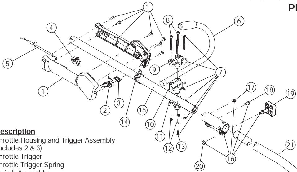
Item Part No. Description
1 753-04234
753-04119 Throttle Trigger
3 791-182690
4 791-182405
5 753-04297
6 791-180687 J-Handle Assembly
7 791-683295 Handle Bracket Assembly (includes 8-13)
8 791-181811 Screw
9 791-181812 Upper Handle Clamp
10 791-181813 Middle Handle Clamp
791-181814 Lower Handle Clamp
12 791-181815 Nut
13 791-145569 Anti-Rotation Screw
14 791-610327 Harness Clip
15 753-1247 Upper Drive Shaft Housing Assembly
16 753-1190 EZ-Link™ Coupler (includes 17-20)
17 791-182057 Screw
18 791-181617 Bolt
791-181981 Adjustment Knob
20 791-181886 Knob Retaining Nut
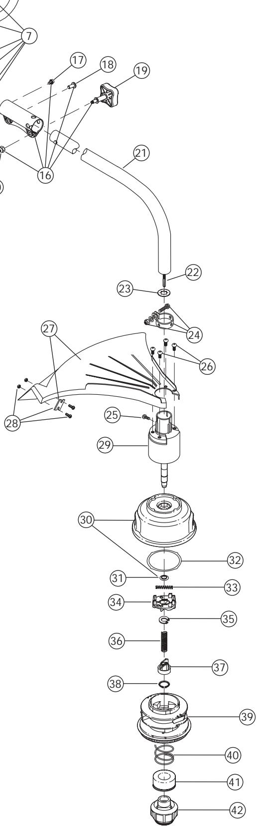
21 753-04304 Lower Drive Shaft Housing Assembly
791-181852 Lower Flexible Drive Shaft
23 791-181560 Palnut
24 791-153597 Lower Clamp Assembly
25 791-145569 Anti-Rotation Screw
26 791-180531 Shield Mounting Hardware
791-181659 Shield and Blade Assembly (includes 28)
28 791-181823 Blade Assembly
791-181857 Bushing Housing Assembly
30 791-181457 Outer Spool Assembly (includes 31)
31 791-181458 Retaining Ring
32 791-181561 Thrust Washer
33 791-181459 Small Spring
34 791-181461 Slider
35 791-181532 E-Clip
36 791-181531 Spring
37 791-181462 Plunger
38 791-181463 C-Clip
39 791-181464 Inner Reel
40 791-181465 Large Spring
41 791-181467 Foam Seal
42 791-181468 Bump Head Knob Assembly
(includes 40 & 41)
Optional Accessories
- 791-180120 Replacement Line, 0.095 Diameter
- 753-04218 Reel and Line Assembly
- 791-682075 Shoulder Strap Assembly
* Items Not Shown
GARANTÍA LIMITADA DEL FABRICANTE PARA:
TROY-BILT®
- FINDING MODEL NUMBER
- CALLING CUSTOMER SUPPORT
- SYMBOL MEANING
- CALIFORNIA PROPOSITION 65 WARNING
- WARNING
- READ ALL INSTRUCTIONS
- BEFORE OPERATING
- SAFETY WARNINGS FOR GAS TRIMMERS
- OTHER SAFETY WARNINGS
- SAVE THESE INSTRUCTIONS
- SAFETY AND INTERNATIONAL SYMBOLS
- MEANING
- SAFETY ALERT SYMBOL
- WARNING - READ OPERATOR'S MANUAL
- WEAR EYE AND HEARING PROTECTION
- KEEP BYSTANDERS AWAY
- UNLEADED FUEL
- OIL
- THROWN OBJECTS AND ROTATING CUTTER CAN CAUSE SEVERE INJURY
- SHARP BLADE
- ASSEMBLY INSTRUCTIONS
- INSTALL AND ADJUST THE J-HANDLE
- INSTALLING THE CUTTING SHIELD
- OIL AND FUEL INFORMATION
- RECOMMENDED OIL TYPE
- ADDING OIL TO CRANKCASE: INITIAL USE
- RECOMMENDED FUEL TYPE
- DEFINITION OF BLENDED FUELS
- USING BLENDED FUELS
- USING FUEL ADDITIVES
- FUELING THE UNIT
- STARTING/STOPPING INSTRUCTIONS
- STARTING INSTRUCTIONS
- STOPPING INSTRUCTIONS
- OPERATING INSTRUCTIONS
- REMOVING THE CUTTING ATTACHMENT OR ADD-ONS
- INSTALLING THE CUTTING ATTACHMENT OR ADD-ONS
- HOLDING THE TRIMMER
- ADJUSTING TRIMMING LINE LENGTH
- TIPS FOR BEST TRIMMING RESULTS
- DECORATIVE TRIMMING
- MAINTENANCE AND REPAIR INSTRUCTIONS
- MAINTENANCE SCHEDULE
- LINE INSTALLATION FOR THE SPEEDSPOOL®
- WINDING THE INNER REEL WITH NEW LINE
- INSTALLING A PRE-WOUND REEL
- RELEASING THE INNER REEL
- CLEANING THE SPEEDSPOOL
- SPEEDSPOOL® REPLACEMENT PARTS
- CHECKING THE OIL LEVEL
- CHANGING THE OIL
- AIR FILTER MAINTENANCE
- CLEANING THE AIR FILTER
- CARBURETOR ADJUSTMENT
- CHECK FUEL
- CLEAN AIR FILTER
- ADJUST IDLE SPEED SCREW
- REPLACING THE SPARK PLUG
- SPARK ARRESTOR MAINTENANCE
- CLEANING
- STORAGE
- LONG TERM STORAGE
- TRANSPORTING
- ACCESSORIES/REPLACEMENT PARTS
- TROUBLESHOOTING
- ENGINE WILL NOT START
- CAUSE
- ACTION
- ENGINE WILL NOT IDLE
- ENGINE WILL NOT ACCELERATE
- ENGINE LACKS POWER OR STALLS WHEN CUTTING
- CUTTING ATTACHMENT WILL NOT ADVANCE LINE
- CUTTING LINE ADVANCES UNCONTROLLABLY
- SPECIFICATIONS
- ENGINE
- DRIVE SHAFT & CUTTING ATTACHMENT
- NOTES
- EPA EMISSION CONTROL WARRANTY STATEMENT
- YOUR WARRANTY RIGHTS AND OBLIGATIONS
- OWNERS WARRANTY RESPONSIBILITIES
- MANUFACTURER'S WARRANTY COVERAGE
- MANUFACTURER'S LIMITED WARRANTY FOR
- TROY-BILT®
- INSTRUCTIONS D'ARRÉT
- ITEM PART NO. DESCRIPTION
- BOOM AND TRIMMER PARTS - MODEL TB425CS
- 4-CYCLE GAS TRIMMER
- OPTIONAL ACCESSORIES
- GARANTÍA LIMITADA DEL FABRICANTE PARA
Brand : MTD
Model : TB425CS
Category : Brush cutter