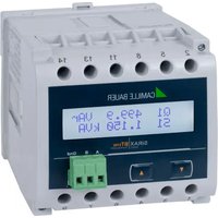
SIRAX BT5700 - Electrical measuring device Camille Bauer - Free user manual and instructions
Find the device manual for free SIRAX BT5700 Camille Bauer in PDF.


| Product Type | Multifunction Power Transducer |
| Dimensions (H x W x D) | 96 x 96 x 80 mm |
| Weight | Approx. 0.4 kg |
| Power Supply | 24-230 V AC/DC (50/60 Hz) |
| Measured Parameters | Voltage, Current, Active Power, Reactive Power, Apparent Power, Power Factor, Frequency, Energy |
| Input Voltage (Nominal) | Up to 600 V AC (L-L) |
| Input Current (Nominal) | 1 or 5 A AC (via external CT) |
| Display | Backlit LCD, multi-line |
| Accuracy (Active Power) | Class 0.5S per IEC 61557-12 |
| Communication Interface | Modbus RTU (RS485) |
| Outputs | 2 digital outputs (alarm/pulse), 1 analog output (0-20 mA or 4-20 mA) |
| Mounting | Panel mount, cutout 92 x 92 mm |
| Protection Rating (Front) | IP54 |
| Operating Temperature | -10°C to +55°C |
| Humidity | 5-95% RH (non-condensing) |
| Electrical Safety | IEC 61010-1, CAT III 300V |
| EMC | IEC 61326-1 |
| Configuration | Via front panel buttons or software |
| Data Logging | Min/max/average values, up to 16 parameters |
| Harmonics Analysis | Up to 31st harmonic |
Frequently Asked Questions - SIRAX BT5700 Camille Bauer
User questions about SIRAX BT5700 Camille Bauer
0 question about this device. Answer the ones you know or ask your own.
Ask a new question about this device
Download the instructions for your Electrical measuring device in PDF format for free! Find your manual SIRAX BT5700 - Camille Bauer and take your electronic device back in hand. On this page are published all the documents necessary for the use of your device. SIRAX BT5700 by Camille Bauer.
USER MANUAL SIRAX BT5700 Camille Bauer
Operating Instructions
SIRAX BT5700
Programmable transducer for heavy current variables


CAMILLE BAUER
Camille Bauer Metrawatt AG
Aargauerstrasse 7
CH-5610 Wohlen/Switzerland
Tel: +41 56 618 21 11
Fax: +41 56 618 21 21
info@cbmag.com
www.camillebauer.com
Legal information
Warning notices
In this document warning notices are used, which you have to observe to ensure personal safety and to prevent damage to property. Depending on the degree of danger the following symbols are used:

If the warning notice is not followed death or severe personal injury will result.

If the warning notice is not followed damage to property or severe personal injury may result.

If the warning notice is not followed the device may be damaged or may not fulfill the expected functionality.
Qualifi ed personnel
The product described in this document may be handled by personnel only, which is qualified for the respective task. Qualified personnel have the training and experience to identify risks and potential hazards when working with the product. Qualified personnel are also able to understand and follow the given safety and warning notices.
Intended use
The product described in this document may be used only for the application specified. The maximum electrical supply data and ambient conditions specified in the technical data section must be adhered. For the perfect and safe operation of the device proper transport and storage as well as professional assembly, installation, handling and maintenance are required.
Disclaimer of liability
The content of this document has been reviewed to ensure correctness. Nevertheless it may contain errors or inconsistencies and we cannot guarantee completeness and correctness. This is especially true for different language versions of this document. This document is regularly reviewed and updated. Necessary corrections will be included in subsequent version and are available via our webpage http://www.camillebauer.com.
Feedback
If you detect errors in this document or if there is necessary information missing, please inform us via e-mail to: customer-support@camillebauer.com
Table of content
1. Introduction ...... 4
1.1 Purpose of this document 4
1.2 Scope of supply 4
1.3 Further documents 4
2. Safety notes 4
3. Device overview 5
3.1 Brief description 5
3.2 Available measurement data 5
4. Mechanical mounting 6
4.1 Mounting
4.2 Demounting of the device 6
5. Electrical connections ...... 7
5.1 General safety notes 7
5.2 Cross sections and tightening torques 7
5.3 Inputs
5.4 Power supply 9
5.5 Connection diagram 9
5.6 Modbus interface RS485 9
6. Commissioning 9
6.1 Operating the device 10
6.2 Setup Parameter Screen 10
7. Programming 13
7.1. Password Protection 1
7.1.1 Change Password New / Change Password 14
7.2 Menu selection 15
7.2.1 System type selection 15
7.2.2 Potential Transformer primary Value 16
7.2.3 Current Transformer Primary Value 16
7.2.4 Current Transformer Secondary Value 17
7.2.5 Energy Display on modbus 17
7.2.6 RESET of parameters 18
7.2.7 Modbus Address 18
7.2.8 Auto scrolling 19
7.2.9 Start current Cutoff 19
7.2.10 Baud Rate 20
7.2.11 Parity and Stop bits 20
7.2.12 Energy rate 20
7.2.13 Energy digit reset count 21
8. Phasor Diagram 22
9. Programming via the RS485 (Modbus) interface 22
10. Service, maintenance and disposal 23
10.1 Repair work and modifi cations 23
10.2 Calibration and new adjustment.... 23
10.3 Cleaning 23
10.4 Disposal 23
10.5 Return 23
11. Technical data 24
12. Dimensional drawings 26
13. Interface Definition Modbus RTU 27
13.1 Modbus functions 27
13.2 Data types 27
1. Introduction
1.1 Purpose of this document
This document describes the universal measurement device SIRAX BT5700. It is intended to be used by:
• Service and maintenance personnel
- Planners
• Installation personnel and commissioning engineers
Scope
This handbook is valid for all hardware versions of the BT5700. Some of the functions described in this document are available only, if the necessary optional components are included in the device.
Required knowledge
A general knowledge in the field of electrical engineering is required. For assembly and installation of the device knowledge of applicable national safety regulations and installation standard is required.
1.2 Scope of supply
• Measurement device SIRAX BT5700
- Safety instructions (multiple languages)
1.3 Further documents
The following documents are provided electronically via www.camillebauer.com:
• Safety instructions SIRAX BT5700
- Operating Instructions SIRAX BT5700
• Data sheet SIRAX BT5700
2. Safety notes

Device may only be disposed in a professional manner!

The installation and commissioning should only be carried out by trained personnel.
Check the following points before commissioning:
- that the maximum values for all the connections are not exceeded, see „Technical data“ section,
- that the connection wires are not damaged, and that they are not live during wiring,
- that the power flow direction and the phase rotation are correct.
The instrument must be taken out of service if safe operation is no longer possible (e.g. visible damage). In this case, all the connections must be switched off. The instrument must be returned to the factory or to an authorized service dealer.
It is forbidden to open the housing and to make modifications to the instrument. The instrument is not equipped with an integrated circuit breaker. During installation check that a labeled switch is installed and that it can easily be reached by the operators.
Unauthorized repair or alteration of the unit invalidates the warranty.
3. Device overview
3.1 Brief description
The universal measuring device SIRAX BT5700 is suited for fixed mounting and the measurement of Voltage, current, frequency, power, energy (active / reactive / apparent), power factor, phase angle, etc in low voltage switchgear. The units are designed for unbalanced load network forms of 3-phase mains with 3- or 4-wire.
3.2 Available measurement data
| Measured Parameters Units 3P 3W 3P 4W | |||
| System Voltage U V • • | |||
| Voltage U1N / U2N / U3N V – • | |||
| Voltage U12 / U23 / U31 V • • | |||
| System Current I A • • | |||
| Current I1 / I2 / I3 A • • | |||
| Neutral Current IN (calc.) A – • | |||
| Frequency F Hz • • | |||
| Active Power P / P1 / P2 / P3 | kW | - • | |
| Reactive Power øQ / Q1 / Q2 / Q3 | kVAr | - • | |
| Apparent Power øS / S1 / S2 / S3 | kVA | - • | |
| Power Factor PF1 / PF2 / PF3 | -- • | ||
| Phase Angle Phi1 / Phi2 / Phi3 | degree | - • | |
| Active Import Energy (8 Digit resolution) | kWh | • • | |
| Active Export Energy (8 Digit resolution) | kWh | • • | |
| Capacitive Reactive Energy (8 Digit resolution) | kVArh | • • | |
| Inductive Reactive Energy (8 Digit resolution) | kVArh | • • | |
| Apparent Energy (8 Digit resolution) | kVAh | • • | |
| Max Current Demand | A • • | ||
| Apparent Power Demand | kVA | • • | |
| Min / Max System Voltage | V • • | ||
| Min / Max System Current | A • • |
4. Mechanical mounting
The SIRAX BT5700 is designed for panel mounting.

Please ensure that the operating temperature limits are not exceeded when determining the place of mounting (place of measurement): -10 ... +55° C
4.1 Mounting
Dimensional drawing BT5700: See section 11
Any mounting position is possible. Device may be clipped onto a top-hat rail according EN50022 in a cabinet.

4.2 Demounting of the device
Disassembly of the device requires that all connected wires be without current. First, remove all push terminals and the wires of the current and voltage inputs. Ensure that possible current transformers are short-circuited before the current connections on the device are opened.

5. Electrical connections

Ensure under all circumstances that the leads are free of potential when connecting them!
5.1 General safety notes

Please observe that the data on the type plate must be adhered to!
The national provisions have to be observed in the installation and material selection of electric lines!
| Symbol Meaning | |
 | Device may only be disposed of in a professional manner! |
 | Double insulation, device of protection class 2 |
| CAT III Measurement category CAT III for current / voltage inputs, power supply and relay outputs | |
 | CE conformity mark. The device fulfi IIs the requirements of the applicable EC directives. See declaration of conformity. |
 | Caution! General hazard point. Read the operating instructions. |
 | Attention: Danger to life! |
| (17TCB) | Please note |
5.2 Cross sections and tightening torques
Terminals 1 ... 14
Single wire: ≤ 4,0mm2 or multiwire with end splices: 2× 2,5mm2
Torque: 0.5 ... 0.6Nm rsp. 4.42 ... 5.31 lbf in
Terminal A, B, G
Single wire: ≤ 1,5mm2 or multiwire with end splices: 2 × 0,5mm2
Torque: max. 0.5 Nm rsp. 4.42 lbf in
5.3 Inputs

All voltage measurement inputs must originate at circuit breakers or fuses rated by 1 Amps. This does not apply to the neutral connector. You have to provide a method for manually removing power from the device, such as a clearly labeled circuit breaker or a fused disconnect switch.
When using voltage transformers you have to ensure that their secondary connections never will be short-circuited.

No fuse may be connected upstream of the current measurement inputs!
When using current transformers their secondary connectors must be short-circuited during installation and before removing the device. Never open the secondary circuit under load.
The connection of the inputs depends on the configured system (connection type).
5.4 Power supply

A marked and easily accessible current limiting switch has to be arranged in the vicinity of the device for turning off the power supply. Fusing should be 10 Amps or less and must be rated for the available voltage and fault current.
5.5 Connection diagram
Three wire, three phase system, unbalanced load, Aron connection (3P 3W)

Direct connection
Four wire, three phase system, unbalanced load (3P 4W)

Direct connection

5.6 Modbus interface RS485
Via the optional Modbus interface measurement data may be provided for a superior system.

1) One ground connection only. This is possibly made within the master (PC).
Rt: Termination resistors: 120 Ω each for long cables (> approx. 10 m)
Rs: Bus supply resistors, 390 Ω each
The signal wires (A, B) have to be twisted. GND (G) can be connected via a wire or via the cable screen. In disturbed environments shielded cables must be used. Supply resistors (Rs) have to be present in bus master (PC) interface. Stubs should be avoided when connecting the devices. A pure daisy chain network is ideal.
You may connect up to 32 Modbus devices to the bus. A proper operation requires that all devices connected to the bus have equal communication settings (baud rate, transmission format) and unique Modbus addresses.
The bus system is operated half duplex and may be extended to a maximum length of 1200 m without repeater.
6. Commissioning

Before commissioning you have to check if the connection data of the device match the data of the plant.
If so, you can start to put the device into operation by switching on the power supply and the measurement inputs.
| SIRAX BT5700 | |
| ORDER CODE: 175275 | |
| SR No.: 15/11/0001 | |
| CLASS: 0.5 CAT III 300V Max. V40.05 | |
| INPUT: 3PH. 440 V L - L, 5A/1A, 45...65Hz | |
| OPTION: RS485 | |
| AUXILIARY: 12...48V DC, 4VA |
Label version RS485
6.1 Operating the device

SIRAX BT5700 can be configured and programmed at site for the following: PT Primary, CT Primary, CT Secondary (5A or 1A) & three wire, three phase system or four wire, three phase system. The front panel has two push buttons through which the User may scroll through the available measurement readings, reset the energy (Import/Export) Min/Max (System Voltage & System Current) & configure the product.
Operation is performed by means of 2 keys:
2 keys "UP" und "DOWN" for navigation and for the selection of values.
6.2 Setup Parameter Screen
![graph TD A["CODE (password)"] --> B["Enter password (Section 7.1)"] B --> C["Change password (Section 7.1.1)"] C --> D["Sys Type (Section 7.2.1)"] D --> E["PT PRI (Section 7.2.2)"] E --> F["CT PRI (Section 7.2.3)"] F --> G["CT SEC (Section 7.2.4)"] G --> H["Energy OP (Section 7.2.5)"] H --> I["RESET…](/content/2026/07/1417113/images/9d7d36b103fe2cae3a2eefd5c965cb5db7d5eb2b3793186fec9be529139c5b56.jpg)

Screen 1: System screen (U, I)

Screen 2: System Power (P)

Screen 3: Line to neutral Voltage (VL1N) (4 Wire only)

Screen 4: Line to neutral Voltage (U2N, U3N) (4 Wire only)

Screen 5: Line to line Voltage (U12)

Screen 6: Line to line (U23, U31) Voltage

Screen 7: Line Current (I1)

Screen 8: line Currents (I2, I3)

Screen 9: System Power factor, Frequency (Pf, F)

Screen 10: Neutral Current (IN) (4 Wire only)

Screen 11: System Active Power (P)

Screen 12: System Powers (Q, S)

Screen 13: Active Energy ( Pinc )

Screen 14: Active energy ∫P_out)

Screen 15: Reactive Energy (∫ Q_inc)

Screen 16: Reactive energy (∫ Q_out)

Screen 17: Apparent energy (∫S)

Screen 18: Min values (Umin, Umax)

Screen 19: Max values (Umin, Umax)

Screen 20: Phase 1 Active Power (P1) (4 Wire only)

Screen 21: Phase 1 Power (Q1, S1) (4 wire only)

Screen 22: Phase 2 Active Power (P2) (4 wire only)

Screen 23: Phase 2 Power (Q2, S2) (4 wire only)

Screen 24: Phase 3 Power Active (P3) (for 4 Wire only)

Screen 25: Phase 3 Power (Reactive/Apparent) (Q3, S3) (4wire only)

Screen 26: Phase angle (phase 1) (Phi1) (for 4 Wire only)

Screen 27: Phase angle (phase 2, 3) (Phi 2, Phi 3) (for 4 Wire only)

Screen 28: Power factor (phase 1) (PF) (for 4 Wire only)

Screen 29: Power factor (phase 2, 3) (PF2, PF3) (for 4 Wire only)
7. Programming
The following sections comprise step by step procedures for configuring the SIRAX BT5700 for individual user requirements.
To access the set-UP screens, press and hold the “☐ DOWN” and “☐ UP” Key simultaneously for 5 seconds. This will take the User into the Password Protection Entry Stage (Section 7.1).
7.1. Password Protection
Password protection can be enabled to prevent unauthorised access to set-UP screens, by default password protection is not enabled. Password protection is enabled by selecting a four digit number other than 0000, setting a password of 0000 disables the password protection.

Enter Password, prompt for first digit. (*Denotes that the digit will be flashing.
Press “ (DOWN) ” key to scroll the value of the first digit From 0 through 9, the value will wrap from 9 round to 0. Press “UP ” key to advance to next digit.
In the special case, where password is "0000", pressing the "UP" key when prompted for first digit will advance to the password "confirmed" screen.

Enter Password, first digit entered, prompt for second digit.
(*Denotes that the digit will be fl ashing).
Press “(DOWN)” key to scroll the value of the first digit From 0 through 9, the value will wrap from 9 round to 0. Press “UP” key to advance to next digit.

Enter Password, second digit entered, prompt for third digit.
(*Denotes that the digit will be fl ashing.
Press "DOWN" key to scroll the value of the first digit From 0 through 9, the value will wrap from 9 round to 0.
Press "UP" key to advance to next digit.

Enter Password, third digit entered, prompt for fourth digit.
(* Denotes that digit will be fl ashing).
Use the "DOWN" key to scroll the value of the fourth digit from 0 through to 9, the value will wrap from 9 round to 0.
Press the "UP" key to advance to verification of the password.

Enter Password, fourth digit entered, awaiting verification of the password.
Password confirmed

Pressing "DOWN" key will advance to the "New/change Password" entry stage (section 7.1.1)
Pressing the "UP" key will advance to the Menu selection screen. (See section 7.2).
Password Incorrect

The unit has not accepted the Password entered. Pressing the "DOWN" key will return to the Enter Password stage.
Pressing the "UP" key exits the Password menu & returns operation to the measurement reading mode.
7.1.1 Change Password New / Change Password

(* indicates that this digit will be fl ashing).
Pressing the "DOWN" key will scroll the value of the fi rst digit from 0 through to 9, the value will wrap from 9 round to 0. Pressing the "UP" key to advance the operation to the next digit & sets the fi rst digit, in this case "2".

New / Change Password, first digit entered, prompting for second digit. (* indicates that this digit will be flashing).
Pressing the "DOWN" key will scroll the value of the second digit from 0 through to 9, the value will wrap from 9 round to 0.
Pressing the "UP" key to advance the operation to the next digit and sets the second digit, in this case to "3".

New / Change Password, second digit entered, prompting for third digit. (* indicates that this digit will be fl ashing).
Pressing the "DOWN" key will scroll the value of the third digit from 0 through to 9, the value will wrap from 9 round to 0.
Pressing the "UP" key to advance the operation to the next digit and sets the third digit, in this case to "4"

New / Change Password, third digit entered, prompting for fourth digit. (* indicates that this digit will be fl ashing).
Pressing the "DOWN" key will scroll the value of the fourth digit from 0 through to 9, the value will wrap from 9 round to 0.
Pressing the "UP" key to advance the operation to the "New Password Confirmed" and sets the fourth digit, in this case to "5"
New Password confirmed

Pressing the "DOWN" key will return to the "New/Change Password".
Pressing the "UP" key will advances to the system type Selection screen. (see section 7.2.1).
7.2 Menu selection
7.2.1 System type selection

This screen is used to set the system type.
System type "3" for 3 phase 3 wire & "4" for 3 phase 4 wire system. Pressing "UP" key accepts the present value and advances to the "Potential transformer Primary value edit menu 7.2.2
Pressing "DOWN" key will enter system type Edit mode and scroll between 3 and 4.
Pressing "UP" key advances to the system type confirmation menu.
System Type Conformation

Pressing "UP" sets the displayed value and will advance to
"Potential Transformer Primary Value
Edit" menu. (See section 7.2.2)
Pressing "DOWN" key will return to the system type "Edit" menu.
7.2.2 Potential Transformer primary Value
The nominal full scale voltage which will be displayed as Line to Line voltage in four wire or 3 wire system. The value represent the voltage in kVLL.
Maximum Potential transformer primary value can be set to 692.8 kVLL or restricted to 666 MVA depends on previously set Current transformer (CT) primary value. The minimum value allowed is 100VLL.

Pressing "UP" key accepts the present value and then advances to Current transformer (CT) Primary value edit menu (section 7.2.3).
Pressing "DOWN" key enters into "Potential Transformer Primary Value Edit" mode.
Initially the multiplier must be selected. Pressing the "DOWN" key will move the decimal point position to the right unit it reaches # # # .# after which it will return to # # # #.
Pressing "UP" key selects the present multiplier (decimal point position) and advances to the "potential Transformer primary digit Edit" mode.
Potential Transformer Primary Digit edit

(* denotes that the digit will be flashing)
Pressing the “DOWN” key will scroll the value of the most significant digit from 0 through to 9 unless the presently displayed Potential Transformer Primary Value together with the Current Transformer Primary Value, previously set, would result in maximum power of greater than 666MVA per phase, in which case the digit range will be restricted.
Pressing "UP" key accepts the present value at the cursor position and advances the cursor to the next less signifi cant digit.
When the least signifi cant digit has been set, pressing "DOWN" key will advance to the "Potential Transformer Primary Value Confir rmation" stage.
Potential transformer Primary value Confir rmation

If scaling is to be corrected, pressing "DOWN" key will return to the "Potential Transformer Primary Value Edit" stage with the digits fl ashing indicating that the multiplier (decimal point position) should be selected.
Pressing "UP" key sets the displayed value and then it will advance to Current transformer Primary Value selection menu (section 7.2.3).
7.2.3 Current Transformer Primary Value
The nominal Full Scale Current that will be displayed as the Line currents. This screen enables the user to display the Line currents inclusive of the transformer ratios, the values displayed represent the Current in Amps.
Maximum Current transformer primary value can be set to 9999 A or restricted to 666 MVA depends on previously set Potential transformer (PT) Primary value.
Pressing "UP" key accepts the present value and advances to the Current transformer Secondary value menu (section 7.2.4)

Pressing "DOWN" key will enter the "Current transformer
Transformer Primary Value Edit" mode. This will scroll the value of the most significant digit from 0 through to 9, unless the presently displayed Current Transformer Primary Value together with the Potential Transformer Primary Value results in a maximum power of greater than 666MVA in which case the digit range will be restricted, the value will wrap.
Example:
If primary value of PT is set as 692.8 kVLL (max value) then primary value of Current is restricted to 1157A.
Pressing "UP" key will advance curser to next less signifi cant digit. (*Denotes that decimal point will be flashing).
The Maximum Power restriction of 666 MVA refers to 120% of nominal current and 120% of Nominal voltage, i.e. 462.8MVA nominal power per phase.
When the least significant digit has been set, pressing "UP" key will advance to the "Current Transformer Primary Value Confirmation" stage.
The minimum value allowed is 1, the value will be forced to 1 if the display contains zero

Current Transformer Primary value confirmation
If the set value is to be corrected, pressing "DOWN" key Will re-enter the CT primary value edit stage.
Pressing "UP" key, sets the displayed value as CT primary and advances to Current transformer Secondary menu (section 7.2.4).
7.2.4 Current Transformer Secondary Value

The screen is used to set the secondary value for Current Transformer.
Pressing "UP" key accepts the present value and advances to Energy display on modbus menu. (section 7.2.5).
Pressing "DOWN" key enter into CT secondary value Edit and scrolls the value between 1 and 5.
After selecting the desired value, Pressing "UP" Enters into CT secondary value confirmation screen.

CT Secondary value confirmation
Pressing "DOWN" key reenters the CT secondary value edit menu.
Pressing "UP" key sets the displayed value as CT secondary and advances to Energy display on modbus menu (section 7.2.5).
7.2.5 Energy Display on modbus
This screen enable user to set energy in terms of Wh / KWh / MWh on RS 485 Output depending as per the requirement. Same applicable for all types of energy.

Pressing "UP" key accepts the presents value
and advances to the "Reset parameter" menu (See section 7.2.6).
Pressing the "DOWN" key will enter the "Energy Display
On Modbus Edit" mode and scroll the value through the values 1, 2 & 3 wrapping back to 1
1: Energy In Wh
2: Energy in kWh
3: Energy in MWh.
Pressing the "UP" key advances to the "Energy Display On Modbus Confirmation" menu.

Energy Display On Modbus Confir rmation.
This screen will only appear following an edit of the Energy Display On Modbus.
Pressing the "DOWN" key will enter the "Energy Display
On Modbus Edit" stage by blanking the bottom line of the display.
Pressing "UP" key sets the displayed value and will advance to the "Reset parameter" menu. (See section 7.2.6)
Note: Default value is set to '2' i.e. Energy on Modbus will be in terms of kWh/kVArh/kVAh resp.
7.2.6 RESET of parameters

This screen is used to Reset the different parameters.
Pressing "UP" key resets the displayed parameters and advances to modbus address menu (section 7.2.7).
Pressing "DOWN" key scrolls the parameters to Reset From None, Energy, Min, Max, All and back to None.
Select the parameters which is to be Reset with "DOWN" Key. To reset the selected parameter press "UP" key.
After pressing "UP" key, it acknowledges the reset of parameter with "DONE" on display as shown.

Further if another parameter is to be reset, press "DOWN" Key to scroll the parameter again.
Pressing "UP" key after DONE message displayed, advances the operation to modbus address menu. (Section 7.2.7)
7.2.7 Modbus Address

This screen allows the user to set device address of instrument for RS 485 communication. The range of allowable address is 1 to 247. Pressing "DOWN" key enters into the Modbus Address edit mode.
Enter Address, prompt for first digit.
* denotes that the Digit will be fl ashing.
Pressing "DOWN" key scrolls the value of fl ashing digit from 0 to 2 and back to 0. Pressing "UP" key changes the curser position to next Less signifi cant digit.

Enter Address, first digit entered, prompt for second digit
* denotes that the Digit will be fl ashing.
Pressing "DOWN" key scrolls the value of flashing digit from 0 to 9 and back to 0.
Pressing "UP" key changes the curser position to next Less signifi cant digit.

Enter address, second digit entered, prompt for third digit.
* denotes that the Digit will be flashing.
Pressing "DOWN" key scrolls the value of fl ashing digit from 0 to 9 and back to 0.
Pressing "UP" key enters the modbus address Confirmation screen.

7.2.8 Auto scrolling


7.2.9 Start current Cutoff


Modbus address Confir rmation
Pressing "UP" key sets the modbus address & enters Into Auto scrolling selection menu (section 7.2.8).
Pressing "DOWN" key re-enters into Modbus address Setting menu.
This screen allows user to enable screen scrolling.
Pressing "DOWN" key scrolls between enable and disable. Select enable for Auto scrolling of screen and select Disable for fixed screen.
Pressing "UP" key enters into Auto scrolling Confirmation screen
Auto Scrolling Confir rmation
Pressing "UP" key, sets the selected option and advances to noise current cutoff menu (section 7.2.9)
Pressing "DOWN" key re-enters the auto scroll menu.
This screen allows user to set low start current cutoff at 30mA. Pressing "DOWN" key enters into edit mode and scrolls between Enable and disable.
Pressing "UP" key accepts the selected option and enters into 30mA cutoff confirmation screen.
30mA cutoff confirmation
Pressing "UP" key sets the selected option and advances to Baud rate selection menu (section 7.2.10).
Pressing "DOWN" key re-enters into 30mA cutoff selection menu.
7.2.10 Baud Rate

This screen allows user to set the baud rate for Rs485 communication.
Pressing "UP" key sets the present value and advances to Parity and stop bits menu (Section 7.2.11).
Pressing "DOWN" key enters into Baud rate Edit mode & scrolls The values from 2400, 4800, 9600 to 19200 & Back to 2400.
Pressing 'UP' key will advance to baud rate Confirmation screen.
Baud rate Confir rmation

Pressing "DOWN" keys re-enters into baud rate edit mode.
Pressing "UP" key sets the displayed value as baud rate and advances the operation to parity and stop bit menu (section 7.2.11).
7.2.11 Parity and Stop bits

This menu allows user to set parity and number of stop bits for Rs485 communication interface.
The parity and number of stop bits are to be set in same menu.
Pressing "UP" key sets the displayed combination of Parity and stop bits and advances the operation to Energy rate selection menu (section 7.2.12).
Pressing "DOWN" key enters into edit mode and scrolls the Combination from Parity: None Stop bit:1, Parity: None Stop bit: 2
Parity: Even Stop bit: 1, Parity: Odd Stop bit: 1 and back to Parity: None Stop bit: 1. After selecting the desired combination, pressing "UP" Key enters into parity and number of stop bit confirmation screen.
Parity and number of stop bit confirmation.
Parity and number of stop bit confirmation

Pressing "DOWN" key re-enters into the Parity and stop bit Edit menu.
Pressing "UP" key, sets the displayed values and advances the operation to Energy rate selection menu. (section 7.2.12).
7.2.12 Energy rate

This menu allows user to set the energy reading Update rate from 1 to 60 minutes.
Pressing "DOWN" key enters into energy rate edit menu and scrolls the value of 10s digit from 0 to 6. If 1st digit is greater than 0 then 10s digit will wrap back to 0 from 5.
* denotes that the digit will be flashing.
Pressing "UP" key shifts the curser position from 10s digit to 1s digit. Value of 1st digit scrolls from 0 to 9 and again Wraps back to 0.
After setting desired value of 1s digit pressing "UP" key Enters into energy rate confirmation screen.
Energy rate confirmation

Pressing "DOWN" key re-enters into energy rate edit menu.
Pressing "UP" key sets the displayed value as energy update rate and then advance the operation to Energy digit reset count menu (section 7.2.13).
If energy rate is set to "00", then it sets "01" min as default value.
7.2.13 Energy Digit reset count

This screen enables user for setting maximum energy count after which energy will rollback to zero depends upon setting of Wh, kWh, & MWh.
Pressing the "UP" key sets the displayed value and then
SIRAX BT5700 exits from setup menu and starts normal operation.
Pressing the "DOWN" key will enter the Energy digit reset count edit mode. This will scroll the value of reset count from 7 to 14 for Wh, from 7 to 12 for KWh & from 7 to 9 for MWh.
E.g. If energy display on modbus is set Wh & If you set Energy digit count to 10 then energy will reset after "9,999,999,999" & then will Rollback to zero. Pressing "UP" key will advance to Energy digit reset count confirmation screen.
Energy digit reset count confirmation

Pressing the "DOWN" key will re-enter Energy digit reset count edit mode.
Pressing the "UP" key sets the displayed value and will exits from setup menu and starts normal operation.
Note:
1) Default value is set to "8" i.e if energy count crosses 8 digit it will rollback to zero.
2) If Energy displays on modbus is set to (2: kWh) & energy digit reset count is set to 12. Energy screen on display will show "----" i.e. energy overflow when energy crosses the 11 digit count.....
3) If Energy displays on modbus is set to (3: MWh) & energy digit reset count is set to 9. Energy screen on display will show “----” i.e. energy overflow when energy crosses the 8 digit count.....
8. Phasor Diagram
Quadrant 1: 0° to 90°
Quadrant 2: 90° to 180°
Quadrant 3: 180° to 270°
Quadrant 4: 270° to 360°
In this diagram a technical visualization of the current and voltage phasors is shown, using a clockwise rotation.

| Connections Quadrant Sign of Active | Power (P) | Sign of Reactive Power (Q) | Sign of Power Factor (PF) | Inductive/ Capacitive |
| Import 1 + P + Q + L | ||||
| Import 4 + P - Q + C | ||||
| Export 2 - P + Q - C | ||||
| Export 3 - P - Q - L |
Inductive means Current lags Voltage
Capacitive means Current leads Voltage
When the instrument displays Active power (P) with “+” (positive sign), the connection is “Import”.
When the instrument displays Active power (P) with “-” (negative sign), the connection is “Export”.
9. Programming via the RS485 (Modbus) interface
Follow the subsequent steps to program the transducer via the RS485 interface and Modbus:
Step 1: Connection
Connect the Modbus cable according to the connection diagram in Chapter 5.5. Please observe also the information in the Modbus (RS485) interface definition in Chapter 13.
Step 2: Programming
Program SIRAX BT5700 via the Modbus RTU interface and the CB-Configurator software. Please observe the detailed Modbus description in Chapter 13.
Connect the power supply to SIRAX BT5700 before programming.
10. Service, maintenance and disposal

For devices that have not been opened in the factory, no warranty or guarantee can be assumed.
10.1 Repair work and modifications
Repair work and modifications shall exclusively be carried out by the manufacturer. Do not open the housing of the device. In case of any tampering with the device, the guaranty claim shall lapse. We reserve the right of changing the product to improve it.
10.2 Calibration and new adjustment
Each device is adjusted and checked before delivery. The condition as supplied to the customer is measured and stored in electronic form.
The uncertainty of measurement devices may be altered during normal operation if, for example, the specified ambient conditions are not met.
10.3 Cleaning
The display and the operating keys should be cleaned in regular intervals. Use a dry or slightly moist cloth for this.

Damage due to detergents
Detergents may not only affect the clearness of the display but also can damage the device.
Therefore, do not use detergents.
10.4 Disposal

The disposal of devices and components may only be realised in accordance with good professional practice observing the country-specific regulations. Incorrect disposal can cause environmental risks.
10.5 Return
All devices delivered to Camille Bauer Metrawatt AG shall be free of any hazardous contaminants (acids, lyes, solutions, etc.). Use original packaging or suitable transport packaging to return the device.

Damage by returning
Damages caused by improper returning, no warranties or guarantees can be given.
11. Technical data
System
Connection types: Three wire, three phase system, unbalanced load
Four wire, three phase system, unbalanced load
Inputs
Nominal current: 1 A / 5 A
Maximum continuous input current: 120% of Rated value
Nominal input current burden: 0,6 VA per Phase
Max short duration current input: 20 x Rated Value (1s application repeated 5 times at 5 min. intervals)
System CT Primary values: Std. Values 1 to 9999 A (1 or 5 A secondaries)
Nominal voltage: 110 V
L-L (63.5 V LN )
Max continuous input voltage: 120% of Rated Value
Max short duration input voltage: 2 x Rated Value (1S application repeated 10 times at 10s intervals)
Nominal input voltage burden: 0.2VA approx. per phase
System PT primary value: 100 V
LL to 692.8 KV LL
Auxiliary Supply
Auxiliary supply burden:
<4VA approx.
Operating Measuring Ranges
| Voltage: | 5 ... 120% of Rated Value |
| Current: | 5 ... 120% of Rated Value |
| Frequency: | 40 ... 70 Hz |
| Power factor: | 0.6 Lag ... 1 ... 0.6 Lead |
Accuracy
| Voltage: | ± 0,5% of range |
| Current: | ± 0,5% of range |
| Frequency: | ± 0,15% of mid frequency |
| Active power: | ± 0,5% of range |
| Re-active power: | ± 0,5% of range |
| Apparent Power: | ± 0,5% of range |
| Active energy: | ± 0,5% of range |
| Re-active energy: | ± 0,5% of range |
| Apparent energy: | ± 0,5% of range |
| Power Factor: | ± 1 % of Unity |
| Angle: | ± 1 % of range (0 - 360) |

Variation due to influence quantity is 100% of class index for all other parameters except energy.
Mechanical attributes
| Orientation: | Any |
| Bezel size: | 96 mm x 96 mm |
| Panel cut out: | 92+0.8 mm x 92+0.8 mm detail see cut out drawing |
| Overall depth: | <80mm |
| Housing material: | Lexan 940 (polycarbonate), |
| V-0 acc. to UL94, self-extinguishing, non-dripping, free of halogen |
Weight: ca. 460 g
Dimensions: see dimensional drawings
Display: 2 Line Display with backlight, update rate approx. 1 sec.
User interface: 2 push buttons
Terminals:
Screw-type
terminals
Reference conditions for Accuracy
Reference: 23 °C ± 2 °C
temperature Input frequency: 50 or 60Hz ± 2%
Input waveform: Sinusoidal (distortion factor 0.005)
Input Voltage: Rated value
Auxiliary supply voltage: Rated Value ± 1 %
Auxiliary supply frequency: Rated Value ± 1 %
Power Factor: 0.8 Lag...1...0.8 Lead
Nominal range of use of influence quantities for measurands
Voltage:
5 ... 120 % of Rated Value
Current:
5 ... 120 % of Rated Value
Input frequency:
Rated Value ± 10 %
Temperature:
0 to 50 °C
Auxiliary supply voltage: Rated Value ± 10 %
Auxiliary supply frequency: Rated Value ± 10 %
Temperature Coefficient:
0.025% / °C for Voltage (50 ... 120% of Rated Value)
(For Rated value range of use 0... 50 °C )
0.05% / °C for Current ( 10 ... 120% of Rated Value )
Error change due to variation of
an influence quantity:
2 * Error allowed for the reference condition applied in the test
Standards
Terms, definitions and test methods:
EN60688
EMC Immunity:
EN61326
10V/m min-Level 3 industrial low level electromagnetic radiation environment EN61000-4-3
Safety:
EN61010-1:2010, EN61010-2:030
IP for water & dust:
EN60529
Isolation
Dielectric voltage withstand test
2.2 kV RMS 50 Hz for 1 minute between all electrical circuits
Environmental
Operating temperature: -5 to 60 °C
Storage temperature:
-20 to +65 °C
Relative humidity:
0 ... 90 %
Warm UP time:
min. 3 minute
Shock :
15g in 3 planes
Vibration:
10 ... 55 Hz, 0.15mm amplitude
Outputs
Modbus (RS485)
via plug-in terminal (A, B, G)
Protocol:
Modbus (RS485)
Baud rate:
2'400, 4'800, 9'600, 19'200 Baud (programmable)
Parity:
Odd or even, with 1 Stop Bit, or None with 1 or 2 Stop Bits
11. Dimensional drawings


13. Interface Defi nition Modbus RTU
SIRAX BT5700 supports Modbus RTU protocol (RS485).
The permissible address range for the BT5700 is between 1 and 247. Broadcast Mode (address 0) is not allowed.
The maximum latency time of an BT5700 is 200ms i.e. this is the amount of time that can pass before the first response character is output.
After sending any query through software (of the Master), it must allow 200ms of time to elapse before assuming that the BT5700 is not going to respond. If slave does not respond within 200 ms, Master can ignore the previous query and can issue fresh query to the slave.
13.1 Modbus functions
Following code functions are provide:
| Function code | Function Address | |
| 03 Read holding registers 40001 to 40081 | ||
| 04 Read input registers 30001 to 30231 | ||
| 16 Presets multiple registers 40001 to 40081 | ||
Example of read out measurement
Query:
| Device address Function code Start address Nr. of register | CRC | |||
| 0x05 | 0x04 | 0x000C | 0x0006 | 0xB18F |
Response:
| Device address | Function code | Nr. of databytes | Databytes | Databytes | Databytes | CRC |
| 0x05 | 0x04 | 0x0C | 0x3F8A5AA7 | 0x3F844A12 | 0x3F85DAD2 | 0x4759 |
Example of set slave address 5 to 2
Query:
| Device address | Function code | Start address | Nr. of register | Nr. of bytes | Databytes 0...3 | CRC |
| 0x01 | 0x10 | 0x0014 | 0x0002 | 0x04 | 0x41700000 | 0xF387 |
Response:
| Device address | Function code | Start address | Nr. of register | CRC |
| 0x05 | 0x10 | 0x0014 | 0x0002 | 0x0048 |
Exception Cases: An exception code will be generated when BT5700 receives ModBus query with valid parity and error check but which contains some other error (e.g. Attempt to set floating point variable to an invalid value). The response generated will be "Function code" + 0x80.
| 01 | Illegal function | The function code is not supported. |
| 02 | Illegal data address | Attempt to access an invalid address or an attempt to read or write part of a fl oating point value. |
| 03 | Illegal data value | Attempt to set a floating point variable to an invalid value. |
13.2 Data types
All information are displayed as 32-bit float. There is no representation for floating point numbers in the Modbus specification.
The IEEE 754 standard as the most often used standard for the representation of floating numbers is applied.
- The first register contains the bits 16 – 31
- The second register contains the bits 0 – 15
32-Bit Float (Real32)
| 31 | 30 | 23 | 22 | 15 | 7 | 0 |
| Exponent | Mantisse | |||||
| Sign | ||||||
| A | B | C | D | |||
| 0x4017 | 0x4C05 | |||||||||||||||||||||||||||||||||||||||||||||||||||||||||||||||||||||||||||||||||||||||||||||||||||||||||||||
| 0 | 1 | 0 | 0 | 0 | 0 | 0 | 0 | 0 | 0 | 0 | 0 | 1 | 0 | 1 | 1 | 1 | 0 | 1 | 0 | 0 | 1 | 1 | 0 | 0 | 0 | 0 | 0 | 0 | 0 | 0 | 1 | 0 | 1 | |||||||||||||||||||||||||||||||||||||||||||||||||||||||||||||||||||||||||||||
| + | Exponent: 128-127=1 | Mantisse=1.01000000000101110100110000000101=1.18200743198394781526789 | ||||||||||||||||||||||||||||||||||||||||||||||||||||||||||||||||||||||||||||||||||||||||||||||||||||||||||||
Measuring value P = 1.18200743198394781526789 * 2 1 = 2.3640149 W
TABLE 1: 3 X Registeradress (measured Parameter)
| Adress (Register) | Name Description | 3P 4W 3P 3W | |||
| 30001 U1N Voltage phase L1 | to N • (L1-N) • (L1-L2) | ||||
| 30003 U2N Voltage phase L2 | to N • (L2-N) • (L2-L3) | ||||
| 30005 U3N Voltage phase L3 | to N • (L3-N) • (L3-L1) | ||||
| 30007 I1 Current in phase L1 | • • | ||||
| 30009 I2 Current in phase L2 | • • | ||||
| 30011 I3 Current in phase L3 | • • | ||||
| 30013 P1 Active power phase | 1 (L1 - N) • - | ||||
| 30015 P2 Active power phase | 2 (L2 - N) • - | ||||
| 30017 P3 Active power phase | 3 (L3 - N) • - | ||||
| 30019 S1 Apparent power phase | 1 (L1 - N) • - | ||||
| 30021 S2 Apparent power phase | 2 (L2 - N) • - | ||||
| 30023 S3 Apparent power phase | 3 (L3 - N) • - | ||||
| 30025 Q1 | Reactive power phase 1 (L1 - N) | • - | |||
| 30027 Q2 | Reactive power phase 2 (L2 - N) | • - | |||
| 30029 Q3 | Reactive power phase 3 (L3 - N) | • - | |||
| 30031 PF1 | Power factor phase 1 (L1 - N) | • - | |||
| 30033 PF2 | Power factor phase 2 (L2 - N) | • - | |||
| 30035 PF3 | Power factor phase 3 (L3 - N) | • - | |||
| 30037 Phi 1 | Phase angle 1 | • - | |||
| 30039 Phi 2 | Phase angle 2 | • - | |||
| 30041 Phi 3 | Phase angle 3 | • - | |||
| 30043 ∅U | Average value of voltages | • • | |||
| 30045 ΣU | Sum of voltages | • • | |||
| 30047 ∅I | Average value of current | • • | |||
| 30049 ΣI | Sum of current | • • | |||
| 30051 P | Average value of active power | • • | |||
| 30053 ΣP | Sum of active power | • • | |||
| 30055 | ∅S | Average value of apparent power | • | • | |
| 30057 ΣS | Sum of apparent power | • • | |||
| 30059 | ∅Q | Average value of reactive power | • | • | |
| 30061 ΣQ | Sum of reactive power | • • | |||
| 30063 | ∅PF | Average value of power factor | • | • | |
| 30065 ΣPF Sum of power factor | • - | ||||
| 30067 | ∅Phi | Average value of phase angle | • | • | |
| 30069 ΣPhi | Sum of phase angle | • - | |||
| 30071 F | System frequency | • • | |||
| 30073 fP_inc | Active power incoming | • • | |||
| 30075 fP_out | Active power outgoing | • • | |||
| 30077 fQ_inc | Reactive Power incoming | • • | |||
| 30079 fQ_out | Reactive Power outgoing | • • | |||
| 30081 fS | Apparent power | • • | |||
| Adress (Register) | Name Description | 3P 4W 3P 3W | |||
| 30133 ∅U max. | Maximum of the voltage average value ● ● | ||||
| 30135 ∅U min. | Minimum of the voltage average value ● ● | ||||
| 30141 ∅I max. | Maximum of the current average value ● ● | ||||
| 30143 ∅I min. | Minimum of the current average value ● ● | ||||
| 30145 ∫P_inc | * Active power incoming (kWh) | ● ● | |||
| 30147 | ∫P_out * | Active power outgoing (kWh) | ● | ● | |
| 30149 ∫Q_inc | * Reactive Power incoming (kvarh) | ● ● | |||
| 30151 ∫Q_out | * Reactive Power outgoing (kvarh) | ● ● | |||
| 30153 ∫S * | Apparent power (kvah) | ● ● | |||
| 30201 U12 | Voltage phase L1 to L2 | ● - | |||
| 30203 U23 | Voltage phase L2 to L3 | ● - | |||
| 30205 U31 | Voltage phase L2 to L1 | ● - | |||
| 30225 IN_calc | Neutral current (calculated) | ● - | |||
| 30513 Variable 1 | Quantity is defined by user (see 40513 ... 40534) | ||||
| 30515 Variable 2 | Quantity is defined by user (see 40513 ... 40534) | ||||
| 30517 Variable 3 | Quantity is defined by user (see 40513 ... 40534) | ||||
| 30519 Variable 4 | Quantity is defined by user (see 40513 ... 40534) | ||||
| 30521 Variable 5 | Quantity is defined by user (see 40513 ... 40534) | ||||
| 30523 Variable 6 | Quantity is defined by user (see 40513 ... 40534) | ||||
| 30525 Variable 7 | Quantity is defined by user (see 40513 ... 40534) | ||||
| 30527 Variable 8 | Quantity is defined by user (see 40513 ... 40534) | ||||
| 30529 Variable 9 | Quantity is defined by user (see 40513 ... 40534) | ||||
| 30531 Variable 10 | Quantity is defined by user (see 40513 ... 40534) | ||||
| 30533 Variable 11 | Quantity is defined by user (see 40513 ... 40534) | ||||
| 30535 Variable 12 | Quantity is defined by user (see 40513 ... 40534) | ||||
| 30537 Variable 13 | Quantity is defined by user (see 40513 ... 40534) | ||||
| 30539 Variable 14 | Quantity is defined by user (see 40513 ... 40534) | ||||
| 30541 Variable 15 | Quantity is defined by user (see 40513 ... 40534) | ||||
| 30543 Variable 16 | Quantity is defined by user (see 40513 ... 40534) | ||||
| 30545 Variable 17 | Quantity is defined by user (see 40513 ... 40534) | ||||
| 30547 Variable 18 | Quantity is defined by user (see 40513 ... 40534) | ||||
| 30549 Variable 19 | Quantity is defined by user (see 40513 ... 40534) | ||||
| 30551 Variable 20 | Quantity is defined by user (see 40513 ... 40534) | ||||
* see Register 40081 (Page 30, Table 2)
TABLE 2: Description of 4X-Registers:
| Adress | Name Read/ | Write | Description | |||||||
| 40005 Energy unit R/W This address is used to set energy unit in Wh, kWh & MWh.Write one of the following value to this address.1: Energy in Wh. 2: Energy in kWh.3: Energy in MWh. | ||||||||||
| 40007 System Voltage R This address is read only and displays System Voltage | ||||||||||
| 40009 System Current R This address is read only and displays System Current | ||||||||||
| 40011 System Type R/W This address is used to set the System type.Write one of the following value to this address.2: 3 Phase 3 Wire3: 3 Phase 4 Wire.Writing any other value will return error. | ||||||||||
| 40015 Reset Energy Counter | W This address is used to reset the Energy Counter.Write zero value to this register to reset the energy counter. Writing any other value will return an error. | |||||||||
| 40019 Rs485 Set-up Code | R/W This address is used to set the baud rate, Parity, Number of stop bits. | |||||||||
| 40043 CT secondary R/W This address is used to read and write the CT secondary value. Write one of the following values to this address.1: 1A CT secondary5: 5A CT secondarywriting any other value will return an error. | ||
| 40071 Passwort R/W This address is used to set & reset the password. Valid Range of Password can be set is 0000 - 9999.1) If password lock is present & if this location is read it will return zero.2) If Password lock is absent & if this location is read it will return One.3) If password lock is present & to disable this lock fi rst send valid pas word to this location then write "0000" to this location4) If password lock is present & to modify 4X parameter fi rst send valid password to this location so that 4X parameter will be accessible for modifi cation.5) If for in any of the above case invalid password is send then meter will return exceptional error 2. | ||
| 40077 Auto-Scroll R/W This address is used to activate or de-activate the auto scrolling.Write 0: Deactivate1: Activate, Writing any other value will return an error. | ||
| 40079 30mA start current R/W This address is used to activate or de-activate the 30 mA start current elimination write0: Deactivate30 (Decimal): ActivateWriting any other value will return an error. | ||
| 40081 Aktualisierungsrate R/W Update rate of the energy meter in the process image (30145 ... 30153) | ||
| 40513 Variable 1 R/W defi nes the value of the register 30513/30514 | ||
| 40514 Variable 2 R/W defi nes the value of the register 30515/30516 | ||
| 40515 Variable 3 R/W | ||
| 40516 Variable 4 R/W | Value Name | |
| 40517 Variable 5 R/W | 0 Voltage UL1 | |
| 40518 Variable 6 R/W | 2 Voltage UL2 | |
| 40519 Variable 7 R/W | 4 Voltage UL3 | |
| 40520 Variable 8 R/W | ... | |
| 50521 Variable 9 R/W | 70 Frequenz | |
| 40522 Variable 10 R/W | ... | |
| 40523 Variable 11 R/W | 144 Active power incoming | |
| 40524 Variable 12 R/W | 224 Neutral current | |
| 40527 Variable 13 R/W | Wert = 3X Register Adress - 30001 | |
| 40528 Variable 14 R/W | ||
| 40529 Variable 15 R/W | ||
| 40530 Variable 16 R/W | ||
| 40531 Variable 17 R/W | ||
| 40532 Variable 18 R/W | ||
| 40533 Variable 19 R/W | ||
| 40534 Variable 20 R/W defi nes the value of the register 30551/30552 | ||


- OPERATING INSTRUCTIONS
- SIRAX BT5700
- LEGAL INFORMATION
- WARNING NOTICES
- QUALIFI ED PERSONNEL
- INTENDED USE
- DISCLAIMER OF LIABILITY
- FEEDBACK
- TABLE OF CONTENT
- INTRODUCTION ...... 4
- SAFETY NOTES 4
- DEVICE OVERVIEW 5
- MECHANICAL MOUNTING 6
- ELECTRICAL CONNECTIONS ...... 7
- COMMISSIONING 9
- PROGRAMMING 13
- PHASOR DIAGRAM 22
- PROGRAMMING VIA THE RS485 (MODBUS) INTERFACE 22
- SERVICE, MAINTENANCE AND DISPOSAL 23
- TECHNICAL DATA 24
- DIMENSIONAL DRAWINGS 26
- INTERFACE DEFINITION MODBUS RTU 27
- INTRODUCTION
- 1.1 PURPOSE OF THIS DOCUMENT
- SCOPE
- REQUIRED KNOWLEDGE
- 1.2 SCOPE OF SUPPLY
- 1.3 FURTHER DOCUMENTS
- SAFETY NOTES
- DEVICE OVERVIEW
- 3.1 BRIEF DESCRIPTION
- MECHANICAL MOUNTING
- 4.1 MOUNTING
- 4.2 DEMOUNTING OF THE DEVICE
- ELECTRICAL CONNECTIONS
- 5.1 GENERAL SAFETY NOTES
- 5.2 CROSS SECTIONS AND TIGHTENING TORQUES
- 5.3 INPUTS
- 5.4 POWER SUPPLY
- 5.5 CONNECTION DIAGRAM
- 5.6 MODBUS INTERFACE RS485
- COMMISSIONING
- 6.1 OPERATING THE DEVICE
- 6.2 SETUP PARAMETER SCREEN
- PROGRAMMING
- PASSWORD PROTECTION
- 7.2 MENU SELECTION
- 7.2.2 POTENTIAL TRANSFORMER PRIMARY VALUE
- 7.2.3 CURRENT TRANSFORMER PRIMARY VALUE
- CURRENT TRANSFORMER PRIMARY VALUE CONFIRMATION
- 7.2.4 CURRENT TRANSFORMER SECONDARY VALUE
- CT SECONDARY VALUE CONFIRMATION
- 7.2.5 ENERGY DISPLAY ON MODBUS
- ENERGY DISPLAY ON MODBUS CONFIR RMATION
- 7.2.6 RESET OF PARAMETERS
- 7.2.7 MODBUS ADDRESS
- MODBUS ADDRESS CONFIR RMATION
- AUTO SCROLLING CONFIR RMATION
- 30MA CUTOFF CONFIRMATION
- 7.2.10 BAUD RATE
- BAUD RATE CONFIR RMATION
- 7.2.11 PARITY AND STOP BITS
- PARITY AND NUMBER OF STOP BIT CONFIRMATION
- 7.2.12 ENERGY RATE
- ENERGY RATE CONFIRMATION
- 7.2.13 ENERGY DIGIT RESET COUNT
- ENERGY DIGIT RESET COUNT CONFIRMATION
- NOTE
- PHASOR DIAGRAM
- INDUCTIVE MEANS CURRENT LAGS VOLTAGE
- CAPACITIVE MEANS CURRENT LEADS VOLTAGE
- PROGRAMMING VIA THE RS485 (MODBUS) INTERFACE
- STEP 1: CONNECTION
- STEP 2: PROGRAMMING
- SERVICE, MAINTENANCE AND DISPOSAL
- 10.1 REPAIR WORK AND MODIFICATIONS
- 10.2 CALIBRATION AND NEW ADJUSTMENT
- 10.3 CLEANING
- DAMAGE DUE TO DETERGENTS
- 10.4 DISPOSAL
- 10.5 RETURN
- DAMAGE BY RETURNING
- TECHNICAL DATA
- SYSTEM
- INPUTS
- REFERENCE CONDITIONS FOR ACCURACY
- NOMINAL RANGE OF USE OF INFLUENCE QUANTITIES FOR MEASURANDS
- STANDARDS
- ISOLATION
- ENVIRONMENTAL
- OUTPUTS
- DIMENSIONAL DRAWINGS
- INTERFACE DEFI NITION MODBUS RTU
- 13.1 MODBUS FUNCTIONS
- EXAMPLE OF READ OUT MEASUREMENT
- EXAMPLE OF SET SLAVE ADDRESS 5 TO 2
- 13.2 DATA TYPES
Brand : Camille Bauer
Model : SIRAX BT5700
Category : Electrical measuring device