
RXV 550 - Off-road motorcycle APRILIA - Free user manual and instructions
Find the device manual for free RXV 550 APRILIA in PDF.
| Product type | Off-road motorcycle |
| Brand | Aprilia |
| Model | RXV 550 |
| Displacement | 549 cm³ |
| Engine type | Single-cylinder 4-stroke, liquid-cooled |
| Bore x Stroke | 100 x 72 mm |
| Compression ratio | 12.5:1 |
| Maximum power | 35 kW (47.6 hp) at 7,500 rpm |
| Maximum torque | 50 Nm at 6,000 rpm |
| Fuel system | Electronic injection, throttle body Ø 40 mm |
| Ignition | Electronic |
| Transmission | 5-speed |
| Final drive | Chain drive, with joining link |
| Fuel tank capacity | 12 L (reserve 2.2 L) |
| Recommended engine oil | AGIP RACING 4T 10W-60 (or equivalent API SG, CCMC G-4) |
| Coolant | AGIP PERMANENT SPEZIAL (protection down to -40°C) |
| Brake fluid | DOT 4 (AGIP BRAKE 4) |
| Fork oil | AGIP FORK 7.5W (SAE 7.5W) |
| Battery | 12 V - 5 W |
| Tires front / rear | 90/90-21 / 140/80-18 (unless otherwise specified) |
| Dry weight | Approximately 140 kg |
| Maintenance | Oil change every 15 h or 3,000 km, complete overhaul every 75 h or 15,000 km |
| Warranty | Legal warranty subject to maintenance at an authorized dealer |
Frequently Asked Questions - RXV 550 APRILIA
User questions about RXV 550 APRILIA
0 question about this device. Answer the ones you know or ask your own.
Ask a new question about this device
Download the instructions for your Off-road motorcycle in PDF format for free! Find your manual RXV 550 - APRILIA and take your electronic device back in hand. On this page are published all the documents necessary for the use of your device. RXV 550 by APRILIA.
USER MANUAL RXV 550 APRILIA
Congratulations on your new RXV.
This innovative motorcycle is designed to provide high performance and great fun under all usage conditions - in other words, it's intent is to revolutionize the concept of Enduro motorcycles. aprilia's first and foremost commitment is to build motorcycles with high technological content, that are extremely safe to ride and will retain their value over time.
IMPORTANT NOTICE ON VEHICLE USE AND LEGAL WARRANTY
apriliaRXV motorcies have been conceived and designed for race-track and off-road competitions. Accordingly, they meet the rules and class requirements currently adopted by major international motocycling associations.
The RXV model has been specifically designed for off-road endurance, "Enduro", racing and not mainly for motocross racing.
Having the motorcycle serviced at the recommended intervals specified in the maintenance charts provided in this manual is critical to avoiding premature wear and tear and the possibility of a failure. To preserve motorcycle performance and avoid severe damage, have the recommended maintenance procedures performed by an authorised aprilia Dealer.
The RXV model come in a restricted form which can be legally used on public roads and is covered by a legal warranty. In order to maintain the warranty, the recommended maintenance must be performed at the specified intervals by an authorised aprilia Dealer and each service must be recorded in the warranty booklet.
Please note that these motorcycles are not suitable for general road use. Gear ratios, the cooling system, suspension set-up, the braking system and engine power delivery are designed for racing, and the operating conditions encountered in competitions differ greatly from those experienced when riding on public roads.
Typical operating conditions that may lead to severe engine damage include, but are not limited to: long stops at traffic lights, highway trips with the engine operating steadily at high or near maximum rpm and drafting vehicles.
Any changes or modifications to the motorcycle, including the de-restricting of the engine, attempting and/or completing performance enhancing modifications, will make the motorcycle illegal to ride on public roads and way and void the legal warranty. A modified motorcycle may be used for racing in organised races approved by competent authorities.
For your own safety, use only genuine aprilia parts and accessories. aprilia disclaims all liabilities in the event non-genuine parts are used and for any resulting damage.
APRILIA WOULD LIKE TO THANK YOU
for choosing one of its products. We have drawn up this manual to show you all the features of your motorcycle. Please read it carefully before riding your motorcycle for the first time. It contains information, tips and precautions for using your vehicle. You will also discover features, details and devices which will reassure you that you have made the right choice. We believe that if you follow our suggestions, you will soon get to know your new motorbike inside and out and it will serve you well for a long time to come. This booklet is an integral part of the vehicle and must be handed over to the new owner should the bike be sold.
The instructions contained in this booklet were written to provide a simple and clear guide for use of the vehicle. The manual also details routine maintenance procedures and regular checks that should be carried out on the vehicle at an authorized aprilia Dealer or Workshop, as well as instructions for some simple repairs. Procedures not described in detail here require the use of special tools and/or specific technical knowledge: we therefore advise you to contact an authorized aprilia Dealer or Workshop if you need them carried out.
Failure to completely observe these instructions will result in serious risk of personal injury.
Safeguarding the environment
Sections marked with this symbol indicate the correct use of the vehicle to prevent damaging the environment.
The incomplete or non-observance of these regulations leads to the risk of serious damage to the vehicle and sometimes even the invalidity of the guarantee.
The signs pictured above are very important. They work to highlight those parts of the booklet that should be read with particular care. As you can see, each sign consists of a different graphic symbol, making it quick and easy to locate the various topics. Before you start the engine, read this booklet carefully, paying particular attention to the chapter on "SAFE RIDING". Your safety and that of other road users depends as much on your ability to respond to other traffic and unexpected occurrences as on your familiarity with your vehicle, the vehicle's efficiency and your knowledge of basic SAFE RIDING techniques. We therefore recommend that you take the time to familiarize yourself with your vehicle, so that you can ride in all riding situations confidently and safely. IMPORTANT This booklet is an integral part of the vehicle and must be kept with the vehicle, even if the vehicle is sold.
General safety rules 12
Foreword 12
Carbon monoxide 13
Fuel. 14
Hot components. 16
Start off and Riding. 16
Warning lights. 17
Coolant. 18
Used engine oil and gearbox oil 20
Brake and clutch fluid. 21
Battery hydrogen gas and electrolyte 22
Stand. 23
Precautions general advice 24
Reporting of defects that affect safety 26
Road regulations and use of the motorcycle 27
Noise emission warranty 27
Tampering 28
Problems that may affect the motorcycle emissions 31
Position of the warning labels 33
Label 1. 34
Label 2. 35
Label 3. 36
Label 4. 36
Label 5. 37
Label 6. 38
Label 7. 38
Your warranty rights and obligations. 39
VEHICLE 49
Arrangement of the main components. 51
53
RÉGLES GÉNÉRALES 11
Regles generales de sureté 12
Prelisses 12
Monoxyde carbone 13
Carburant. 14
Composantschauds. 16
Départ. 16
voyants 17
Violation/Falsification 28
Locking the handlebar 65
Horn button 65
Turn signal selector 66
High/low beam selector 66
Start-up button 67
Engine stop switch 67
Opening the saddle. 70
The identification. 70
USE 73
74
Refueling. 77
Rear shock absorbers adjustment. 80
Front fork adjustment. 84
Running-In. 86
Starting the engine 88
Stopping the engine 94
Stand. 96
Safe driving. 96
Load 112
MAINTENANCE 113
Engine oil level 114
Engine oil change. 117
Gearbox oil level. 120
Tires. 123
Spark plug removal. 124
Air filter removal. 128
Cooling fluid level 131
Checking the brake fluid level. 136
Battery. 146
Fuses. 147
Lights. 152
Front light group. 153
Headlight adjustment. 154
Front and rear disc brake 156
Periods of inactivity 160
Instruments de bord analogiques 54
Groupe méoons 54
Display/ecran digital. 58
Cleaning the vehicle. 162
Transport. 165
Transmission chain. 165
Chain clearance check. 167
Chain clearance adjustment. 168
Checking wear of chain, front and rear sprockets. 169
Chain lubrication and cleaning. 171
TECHNICAL DATA. 173
Toolkit. 180
SPARE PARTS AND ACCESSORIES 183
Warnings. 184
SCHEDULEDMAINCEPTION 185
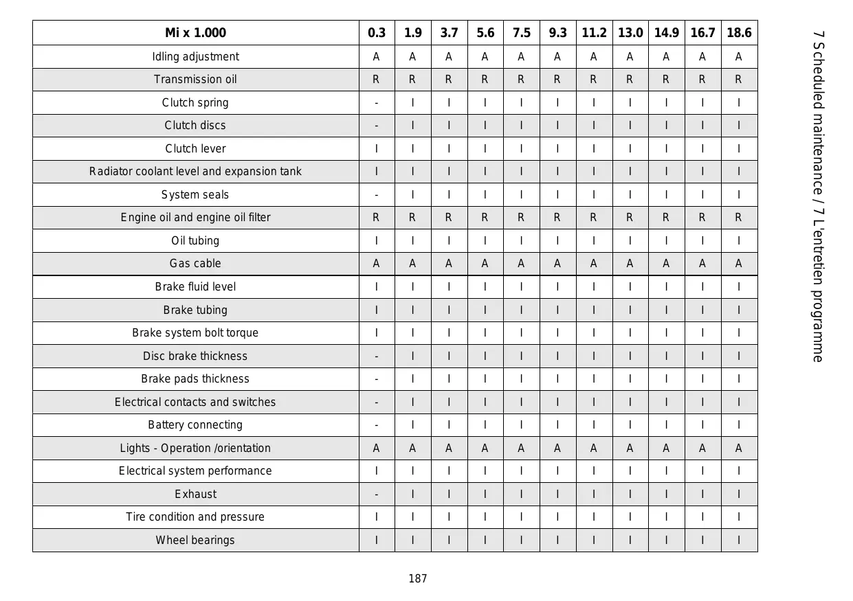
Scheduled servicing table. 186
Trousse a outfits. 180
PIECES DETACHEES ET ACCESSOIRES 183
Avertissements. 184
L'ENTRETIEN PROGRAMME 185
General safety rules
This manual is subdivided into sections, chapters, and paragraphs, based on the topic. The procedures described have been divided by individual operations and each operation is indicated with . The numbered components shown in the pictures are identified in the text with a number in parentheses and the respective symbol.
THIS USE AND MAINTENANCE BOOKLET IS AN IMPORTANT PART OF YOUR VEHICLE. ALWAYS KEEP IT WITH YOUR VEHICLE, ALSO IN CASE OF RESALE.
Premisses
N.B.
CE MANUEL D'UTILISATION ET D'ENTRETIEN FAIT PARTIE INTÉGRANTE DE VOTRE VÉHICULE. LE CONSER-VER TOUJOURS AVEC LE VÉHICULE MÈME EN CAS DE REVENTE.
aprilia created this use and maintenance booklet to provide you, as the driver, with correct and current information. However, given the fact that aprilia is continually improving the design of its vehicles, it is possible that there may be slight differences between the characteristics of your vehicle and those outlined in this manual. For any clarification you may need about your vehicle, contact your local aprilia Dealership, which will always have the most current information available from the company. For checks and
repairs not expressly described in this use and maintenance booklet, for purchase of original spare parts, accessories and other aprilia products, and for assistance with specific problems, contact your local aprilia Dealership or Service Center. The professionals there will provide you with quick and thorough assistance.
Thanks for having chosen aprilia.
Good riding!
This use and maintenance booklet is protected by copyright law in all countries, and total or partial reproduction using any printing or electronic method is prohibited.
If it is necessary to start the engine in order to perform maintenance services, make sure the area in which it will be worked on is well-ventilated. Never let the engine run in enclosed areas.
When it is necessary to work in an enclosed area, be sure to use a system that vents the exhaust outside.
Monoxyde carbone
Keep gasoline out of the reach of children. Gasoline is toxic. Do not use your mouth to siphon gasoline. Avoid having gasoline in contact with your skin. If you should accidentally come into contact with gasoline, change your clothes immediately, and thoroughly wash the area that was in contact with the gasoline with warm water and soap. If you should accidentally swallow gasoline, do not induce vomiting. Drink a large glass of
ATTENTION

LES FUMÉES D'ÉCHAPPEMENT CONTIENNENT DU MONOXYDE DE CARBONE, UN GAZ NOCIF QUI PEUT PROVOUER LA PERTE DE CONNAISSANCE, VOIRE LA MORT.
ATTENTION

LE MONOXYDE DE CARBONE EST INODORE ET INCOLORE:IL NE PEUT PAS ETRE DETECTE AVEC LE NEZ, LES YEUX OU D'AUTRES ORGANES SENSORIELS. NE RESPIRER LES FUMÉES D'ÉCHAPPEMENT EN AUCUNE CIRCONSTANCE.
Carburant
clean water or milk and consult a doctor immediately.
If gasoline should come in contact with your eyes, rinse them with a large amount of clean, fresh water and consult a doctor immediately.
IMPORTANT

FUEL USED FOR OPERATION OF INTERNAL COMBUSTION ENGINES IS HIGHLY FLAMMABLE AND UNDER CERTAIN CONDITIONS CAN CAUSE EXPLOSIONS. FOR THIS REASON, REFUELING AND MAINTENANCE SHOULD BE PERFORMED IN A WELL-VENTILATED AREA WITH THE ENGINE TURNOED OFF. DO NOT SMOKE WHILE REFUELING, WHILE WORKING, OR IN THE PRESENCE OF FUEL VAPORS. AVOID ALL CONTACT WITH OPEN FLAMES, SPARKS, OR OTHER SOURCES THAT CAN CAUSE FIRES OR FUEL VAPOR EXPLOSIONS.
GASOLINE IS A DANGEROUS SUBSTANCE AND SHOULD NOT BE RELEASED INTO THE ENVIRONMENT. ALWAYS USE APPROPRIATE DISPOSAL METHODS.
KEEP OUT OF REACH OF CHILDREN
MÉTHODES D'ELIMINATION APPROPRIÉES.
TENIR HORS DE PORTÉE DES ENFANTS.
Hot components
IMPORTANT

THE ENGINE AND ALL EXHAUST SYSTEM COMPONENTS, AS WELL AS THOSE OF THE BRAKING SYSTEM BECOME EXTREMELY HOT AND REMAIN HOT EVEN AFTER THE VEHICLE AND THE ENGINE ARE TURNED OFF. AFTER RIDING YOUR VEHICLE, BEFORE TOUCHING ANY COMPONENT OF THE VEHICLE, MAKE SURE THAT IT HAS COOLED ENOUGH TO BE HANDLED SAFELY.
Start off and Riding
IMPORTANT
IF DURING YOUR RIDE, THE GASOLINE LIGHT ON YOUR PANEL LIGHTS UP, IT MEANS THAT YOU HAVE ENTERED INTO THE RESERVE AREA.
Composants chauds
ATTENTION

LE MOTEUR ET TOUS LES COMPOSANTS DU SYSTEME D'ÉCHAPPEMENT, TOUT COMME LE SYSTEME DE FREINAGE, DEVIENNENT TRÉS CHAUDS ET RESTENT DANS CET ÉTAT même ÀPRES L'ARRÊT DU VÉHICULE ET DU MOTEUR. AVANT DE MANIPULER UN QUELCONQUE COMPOSANT DU VÉHICULE ÀPRES LA MARCHE, S'ASSURER QU'IL AIT SUFFISAMMENT REFROIDI POUR POUVOIR ÉTRÉ MANIPULÉ.
Départ
ATTENTION
L'ALLUMAGE DU VOYANT DE LA RÉSERVE DE CARBURANT SUR LE TABLEAU DE BORD DURANT LA CONDUITE SIGNALE L'ENTREE DANS LA ZONE DE RÉSERVE.
YOU SHOULD REFUEL YOUR VEHICLE AS SOON AS POSSIBLE.
POURVOIR AU PLUS VITE AU RAVITAILLEMENT EN CARBURANT.
Warning lights

IF THE ALARM LIGHT AND THE WORDS "SERVICE" LIGHT UP WHILE THE ENGINE IS FUNCTIONING NORMALLY, THIS MEANS THAT THE ELECTRONIC CENTRAL UNIT HAS FOUND AN ANOMALY.
IN MANY CASES THE ENGINE MAY CONTINUE TO PERFORM, BUT WITH REDUCED PERFORMANCE; IMMEDIATELY CONTACT AN Official aprilia Dealership.

IF THE WARNING LIGHT AND THE WORDS ENGINE OIL PRESSURE REMAIN ILLUMINATED ON THE DISPLAY, OR THEY ILLUMINATE DURING NORMAL ENGINE OPERATION, THIS MEANS THAT THE OIL PRESSURE IN THE CIRCUIT IS INSUFFICIENT. IN THIS CASE THE ENGINE MUST BE SHUT OFF IMMEDIATELY IN ORDER TO PREVENT POSSIBLE DAMAGE.
voyants

SI LE VOYANT D'ALARME ET ÉVENTUELLEMENT LEMESSAGE « SERVICE » S'ALLUMENT LORS DU FONCTIONNEMENT NORMAL DU MOTEUR, LA CENTRALE ÉLECTRONIQUE A DETECTÉ UNE ANOMALIE.
FIRE HAZARD: Under certain conditions, the ethylene glycol found in the coolant can be flammable: the flames are invisible but can still cause burns.
DO NOT POUR COOLANT INTO THE EXHAUST SYSTEM OR INTO ENGINE PARTS BECAUSE THEY COULD BE HOT AND CAUSE THE COOLANT TO CATCH FIRE, CAUSING BURNS. BEAR IN MIND THAT THE FLAMES ARE INVISIBLE.
COOLANT (ETHYLENE GLYCOL) CAN IRRITATE THE SKIN AND IS TOXIC IF INGESTED.
Used engine oil and gearbox oil
IMPORTANT


WASH YOUR HANDS VERY CAREFULLY AFTER HAVING HANDLED OIL: ENGINE OIL OR TRANSMISSION FLUID CAN CAUSE SERIOUS DAMAGE TO THE SKIN IF HANDLED FOR LONG PERIODS OF TIME OR REGULARLY. WE RECOMMEND THAT YOU WEAR LATEX GLOVES OR THE EQUIVALENT NON-LATEX PRODUCT WHILE PERFORMING VEHICLE MAINTENANCE.
ALWAYS USE APPROPRIATE DISPOSAL METHODS. OIL IS DANGEROUS FOR THE ENVIRONMENT AND FEDERAL LAW PROHIBITS UNAUTHORIZED DISPOSAL. BRING USED OIL TO AN APPROPRIATE OIL COLLECTION CENTER OR ASK THAT IT BE TAKEN AWAY BY THE USED OIL COLLECTION COMPANY NEAREST TO YOU.
KEEP OUT OF REACH OF CHILDREN
Brake and clutch fluid
IMPORTANT

BRAKE FLUID IS EXTREMELY TOXIC. NEVER INGEST BRAKE FLUID. IF YOU SHOULD ACCIDENTALLY SWALLOW BRAKE FLUID, DRINK A LARGE GLASS OF CLEAN WATER OR MILK AND CONSULT A DOCTOR IMMEDIATELY.
BRAKE FLUID IS HIGHLY IRRITATING TO SKIN AND EYES. IF YOU SHOULD ACCIDENTALLY COME INTO CONTACT WITH BRAKE FLUID, CHANGE YOUR CLOTHES, WASH IMMEDIATELY WITH SOAP AND HOT WATER, AND CONTACT A DOCTOR AS SOON AS POSSIBLE.
BRAKE FLUID IS HIGHLY IRRITATING TO SKIN AND EYES. IF BRAKE FLUID SHOULD COME INTO CONTACT WITH YOUR EYES, IMMEDIATELY FLUSH THEM WITH A LARGE AMOUNT OF FRESH, CLEAN WATER AND CONTACT A DOCTOR.
KEEP BRAKE FLUID OUT OF REACH OF CHILDREN.
Battery hydrogen gas and electrolyte
IMPORTANT

THE BATTERY RELEASES EXPLOSIVE GASES; KEEP CIGARETTES, FLAMES AND SPARKS AWAY FROM THE BATTERY. PROVIDE FOR ADEQUATE VENTILATION DURING THE USE OR RECHARGING OF THE BATTERY.
THE BATTERY CAN RELEASE HARMFUL GASES: DURING USE AND RECHARGING, MAKE SURE THAT THE AREA IS VENTILATED IN AN ADEQUATE MANNER, AND DO NOT INHALE THE GASES RELEASED DURING RECHARGING.
THE BATTERY CONTAINS SULFURIC ACID (ELECTROLYTE). CONTACT WITH SKIN OR EYES CAN CAUSE SERIOUS BURNS. ALWAYS WEAR PROTECTIVE CLOTHING, RUBBER GLOVES, AND A MASK OR SAFETY GLASSES WHEN WORKING WITH THE BATTERY, ESPECIALLY WHEN FILLING THE BATTERY WITH ELECTROLYTE OR WATER.
IN CASE OF CONTACT WITH THE SKIN: RINSE WITHLots OF WATER.
IN CASE OF CONTACT WITH THE EYES: RINSE WITH Lots OF WATER
KEEP THE BATTERY AND ELECTROLYTE OUT OF REACH OF CHILDREN.
EN CAS DE CONTACT AVEC LA PEAU: RINCER ABONDAMMENT À L'EAU.
EN CAS DE CONTACT AVEC LES YEUX: RINCER ABONDAMMENT À L'EAU PENDANT AU MOINS 15 MINUTES. CONSULTER IMMÉDIATIMENT UN MÉDECIN.
L'ÉLECTROLYTE EST TOXIQUE :EN CAS D'INGESTION ACCIDENTELLE DE L'ÉLECTROLYTE, BOIRE DE L'EAU OU DU LAIT EN ABONDANCE ET POURSUIVRE AVEC DU LAIT DE MAGNÉSIE OU DE L'HUILÉ VÉGÉTALE. CONSULTER IMMEDIATEMENT UN MÉDECIN.
TENIR LES BATTERIES ET L'ÉLECTROLYTE HORS DE LA PORTÉE DES ENFANTS.
Stand

WHEN THE VEHICLE IS NOT IN USE: DO NOT SIT ON THE VEHICLE WHILE IT IS NOT IN USE AND ON THE SIDE STAND OR CENTRAL STAND. THE PARKING STANDS ARE DESIGNED EXCLUSIVELY FOR KEEPING THE VEHICLE IN EQUILIBRIUM. THE ADDITIONAL WEIGHT OF THE DRIVER,
Bequille

LORSQUE LE VEHICULE EST ARRÊTE : NE PAS S'ASSEoir SUR LE VEHICULE PENDANT QU'IL EST POSI-TIONné SUR LA BEQUILLE (LATÉRALLE OU CENTRALE). LES BEQUILLES DE STATIONNEMENT SONT CONÇUES EXCLUSIVEMENT POUR MAINTENIR LE VEHICULE EN ÉQUILIBRE. LE POIDS SUPPLEMENTaire D'UN
PASSenger OR BOTH CAN CAUSE THE VEHICLE TO FALL, CAUSING SERIOUS INJURY OR DEATH.
BEFORE MOVING THE VEHICLE: CHECK THAT THE SIDE STAND AND/OR CENTRAL STAND ARE COMPLETELY LIFTED. IF THE STAND IS NOT COMPLETELY LIFTED, THERE IS A RISK OF SERIOUS INJURY OR DEATH.
CONDUCTEUR, D'UN PASSAGER OU DES DEUX POURRAIT FAIRE TOMBER LE VEHICULE, CE QUI POURRAIT PROVOQUER DE GRAVES BLESSURES, VOIRE LA MORT.
AVANT DE DÉPLACER LE VÉHICULE: VERIFIER QUE LA BÉQUILLE (LATERALE OU CENTRALE) EST COMPLÉTEMENT SOULEVEE. SI LA BÉQUILLE N'EST PAS COMPLÉTEMENT SOULEVEE, ON RISQUE DE SUBIR DE GRAVES BLESSURES, VOIRE LA MORT.
Precautions general advice
In case of questions about your rights and responsibilities under the warranty, contact Piaggio Group Americas, Inc., 140 East 45th Street, 17th Floor New York, NY 10017, Phone number: (212) 380 4400, the U.S. Environmental Protection Agency, 2000 Traverwood Ann Arbor, MI 48105 or the California Air Resources Board at P.O. Box 8001, 9528 Telstar Avenue, El Monte, CA 91734-8001. If you believe that your vehicle has a defect that could cause a collision, injuries or death, immediately inform both the National Highway Traffic Safety Administration (NHTSA) and aprilia. If the NHTSA receives other similar information, they may open an investigation and if they find the presence of a safety defect for a group of vehicles, they may order a
recall or correction campaign. In any case, NHTSA will not involve itself in individual problems between yourself, your dealership or aprilia. To contact NHTSA, you can call the toll-free Auto Safety Hotline 1-800-424-9393 (or 366-0123 in Washington, D.C.) or you can write to: NHTSA, U.S. Department of Transportation, Washington, D.C. 20590. Additional information about motor vehicle safety can be found by calling the toll-free number.
Your safety and the safety of the persons around you depend not only on your riding ability, but also on your knowledge of your vehicle and safety rules.
For this reason, it is essential that you do not use your vehicle on public streets or on the highway until you have attended a course organized by a qualified and serious safety organization, for example the MOTORCYCLE SAFETY FOUNDATION.
If you believe that your vehicle has a defect that could cause accidents or death, you must immediately inform the National Highway Traffic Safety Administration (NHTSA), a section of the U.S. Department of Transportation.
After receiving information about such defects the NHTSA may open an investigation to discover if there is a group of defective vehicles on the market. At that point, they may initiate an informational campaign to recall said vehicles from the market. In any case, neither the NHTSA nor the Department of Transportation will be involved in personal issues between the consumer and the maker,
It is possible to obtain additional information by telephoning the appropriate number.
Reporting of defects that affect safety
Except where specified in this Use and Maintenance Manual, do not disassemble any mechanical or electrical component.
IMPORTANT
SOME OF THE VEHICLE'S CONNECTORS CAN BE EASILY CONFUSED AND IF ATTACHED INCORRECTLY
CAN CAUSE PROBLEMS WITH NORMAL VEHICLE PERFORMANCE.
VENT NUIRE AU FONCTIONNEMENT NORMAL DU VEHICULE.
Road regulations and use of the motorcycle
Norms of the road vary from one state to another and from one country to another. It is very important to familiarize yourself beforehand with the rules of the road that apply to all countries, states and cities in which the vehicle will be used.
Noise emission warranty
Piaggio & Co. S.p.A guarantees that the exhaust system conforms, at the time of selling, with all USEPA federal standards on noise emissions. The present warranty is also extended to the first person that purchases the exhaust system without the intention of reselling it, and all subsequent purchasers.
Warranty claims should be sent to:
Piaggio Group Americas, Inc.
Aprilia Technical Service
760 W. 16th Street, Bldg. L.
Costa Mesa, CA 92627
Aprilia Technical Service
760 W. 16th Street, Bldg. L.
Origin of the emissions
IMPORTANT

THE COMBUSTION PROCESS CREATES CARBON MONOXIDE AND HYDROCARBONS. THE HYDROCARBON CHECK IS VERY IMPORTANT BECAUSE UNDER CERTAIN CONDITIONS THESE CAN REACT TO SUNLIGHT AND CREATE PHOTOCHEMICAL SMOG.
CARBON MONOXIDE DOES NOT REACT IN THE SAME WAY, BUT IT IS TOXIC AND HARMFUL. aprilia uses a CARBURETOR SYSTEM BASED ON A "LEAN" FUEL MIX AND OTHER SYSTEMS TO REDUCE THE PRODUCTION OF CARBON MONOXIDE AND HYDROCARBONS.
Tampering with the noise control system is prohibited. Federal law prohibits the
Violation/Falsification
following actions or acts that could cause them:
a) The removal of any device or element intended to control noise emissions included in all new vehicles, or any action, on the part of any person, intended to render these inoperative, except for purposes of maintenance, repair, or substitution, either before delivery to the final purchaser or during utilization of the vehicle,
or
b) use of the vehicle after said device or element has been removed or made inoperable by any person.
The following actions are also defined as tampering:
a) Removal or perforation of the muffler, baffles, inflow tubes, or any other component that conveys exhaust fumes.
b) Dismantling or perforating any component of the intake system.
c) Insufficient maintenance.
d) Substitution of any moving parts or any parts of the intake or exhaust systems with parts different than those specified by the manufacturer.
e) Removal of decals or warning labels concerning emissions or safe vehicle functioning. Damages resulting from removal of decals or warning labels are not covered under the conditions of the limited Warranty applied to new
vehicles.. In addition, many countries may refuse to allow use of a vehicle lacking warning labels relative to emissions or safety that must be properly attached. The owner of the vehicle must recognize the fact that Piaggio Group Americas, Inc. will not recognize any warranty when the vehicle or any of its components have become defective as a consequence of: infractions, negligence, improper maintenance, unauthorized modifications or use in racing, in both legal and illegal races, or in events such as Track Day.
IMPORTANT

THIS PRODUCT MUST BE REPAIRED OR REPLACED IF THE NOISE PRODUCED BY THE VEHICLE SHOULD INCREASE SIGNIFICANTLY DURING USE. IF THESE ACTIONS ARE NOT TAKEN, THE OWNER OF THE VEHICLE COULD FACE FINES ACCORDING TO LOCAL, STATE AND FEDERAL LAWS.
Problems that may affect the motorcycle emissions
Whenever you encounter one of the following warning signs, immediately have your vehicle checked and repaired at your local aprilia Dealership.
Symptoms:
- Difficulty starting or stalling after starting.
- Unstable idling.
- Lack of ignition or spark advance while accelerating.
- Delayed combustion (spark advance).
- Poor engine performance, reduced manageability, or excessive fuel consumption.
Position of the warning labels (01_02)
- Label indicating type-approval adhesive label
- Manufacturer adhesive label
- Adhesive label for sound emissions
- Adhesive label for pollutants emission
- Adhesive label for carbon filter
- Adhesive label for tire pressure and chain tension
Legende:
Adhesive label for sound emissions.
Étiquette 3 (01_06)
Adhesive label for pollutants emission.
Étiquette 4 (01_07)
Adhesive label for carbon filter. Only for the State of California.
Étiquette 5 (01_08)
Adhesive label for tire pressure and chain tension.
Label 7 (01_10)
ECE transfer
Only for Canada
Étiquette 6 (01_09)
Your warranty rights and obligations
aprilia - DECLARATION OF THE WARRANTY FOR THE EMISSION CONTROL SYSTEM
YOUR RIGHTS AND RESPONSIBILITIES UNDER THE WARRANTY
The United States Environmental Protection Agency, the California Air Resources Board and the aprilia Division of Piaggio & C. S.p.A. (hereafter "aprilia") are pleased to present the emission control system warranty for your motorcycle produced in 1999 or thereafter. In California new motorized vehicles must be designed, constructed and equipped to comply with the severe antismog standards of the United States. aprilia must guarantee your motorcycle's emission control system for a period of time listed below, with the exception of violations, negligence or improper maintenance of your motorcycle.
Your emission control system may include components such as the carburetor, or the carburetor injection system, the ignition system, the catalytic converter and the engine computer. It may also include tubes, belts, connectors and other groups connected to emissions.
Where a legitimate condition exists, aprilia will repair your motorcycle for free, including diagnosis, spare parts, and labor.
Class I motorcycles (3.05 - 10.31 cu in (50 - 169 cc)): for a period of use of five (5) years or 7,456 mi (12.000 km) based on the condition that occurs first.
Class II motorcycles (10.37 - 17.02 cu in (170 - 279 cc)): for a period of use of five (5) years or 11,184 mi (18.000 km) based on the condition that occurs first.
Class III motorcycles (17.09 cu in (280 cc) and over): for a period of use of five (5) years or 18,641 mi (30.000 km) based on the condition that occurs first.
If an emission control related component on your motorcycle is defective, it will be repaired or replaced by aprilia. This is your WARRANTY ON DEFECTS for the emission control system.
- As the owner, you are responsible for having the maintenance indicated in your use and maintenance manual carried out.
GARANTIE DU PROPRIÉTAIRE
RESPONSABILITÉ
aprilia recommends that you save all receipts relating to maintenance performed on your motorcycle even if aprilia cannot negate the warranty solely for the lack of receipts or demonstration that all scheduled maintenance has been carried out.
It is your responsibility to have your vehicle checked at a prlia Dealership as soon as a problem presents itself. Warranty repairs must be conducted within a reasonable time period, which shall not exceed 30 days.
- As the owner of your motorcycle, you should be aware that aprilia may deny your warranty if your motorcycle or one of its components becomes defective as a result of violations, negligence, improper maintenance or unauthorized modifications.
In case of questions about your rights and responsibilities under the warranty, contact Piaggio Group Americas, Inc., 140 East 45th Street, 17th Floor New York, NY 10017 USA or the California Air Resources Board at P.O. Box 8001, 9528 Telstar Avenue, El Monte, CA 91734-8001.
Piaggio & C. S.p.A., Via G. Galilei, 1, 30033 Noale (VE) Italia (hereafter "aprilia") guarantees that all aprilia motorcycles produced in 1999 and from then on which include front, rear and brake lights as standard parts are sanctioned for street use:
a) they have been designed, constructed, and equipped in conformance with all United States Environmental Protection Agency (US Environmental Protection Agency) and the California Air Resources Board norms in force at the moment of the initial sale to the public;
and
b) they have no materials or work defect which could cause nonconformance with the United States Environmental Protection Agency and the California Air Resources Board norms in force for a period of use which is based on engine displacement: 3,728 miles (6.000 km), if the engine displacement is less than 3.05 cu in (50 cc); 7,456 mi (12.000 km) if the engine displacement is less than 10.37 cu in (170 cc); and 11,184 mi (18.000 km) if the engine displacement is equal to or greater than 10.37 cu in (170 cc), but in any case less than 17.09 cu in (280 cc); or 18,641 mi (30.000 km) if the engine displacement is greater to or equal to 17.09 cu in (280 cc); or 5 (five) years from
aprilia - DÉCLARATION DE GARANTIE LIMITÉE SUR LE SYSTème DE CONTROLLE DES ÉMISSIONS
the original date of sale to the public, whichever comes first.
Defects under warranty must be repaired at an Official aprilia Dealership in the United States, during normal working hours, and in conformance with the Clean Air Act and all other applicable United States Environmental Protection Agency and California Air Resources Board norms. All components replaced under the above indicated warranty become the property of Piaggio Group Americas, Inc.
Only in the State of California, the components under warranty connected with emissions control are defined specifically by that state's Emissions Related Parts List. The following parts are covered under the warranty: carburetor and internal components, air induction system, fuel tank; fuel injection system; spark advance mechanism; crank case breather tube; air-blocking valves; fuel tank cap for vehicles with evaporative emissions control; oil top up cap; pressure control valve; vapor/fuel separator; canister; igniters; switch regulators; ignition coils; ignition wires; ignition points; condensers and spark-plugs that are defective before the
I - Couverture
first scheduled replacement; and all tubes, clamps, joints and tubes directly used on the above components. Because the components used for emission control vary from model to model, some models may not use all the above components and other models may have different components with equivalent functions.
Only in the State of California, as provided under California's Administrative Code, are emergency emissions system repairs allowed to be performed by third parties instead of an Official aprilia Dealership. An emergency situation is one in which an Official aprilia Dealership is not available, or a part is not available and will not be within 30 days, or in which the repair will not be completed within 30 days. In the case of an emergency repair, any type of spare part may be used. Piaggio Group Americas, Inc. will reimburse the owner for costs, including the diagnosis, without exceeding the recommended consumer price suggested by aprilia for all pieces replaced covered by warranty, as well as labor, based on the labor times recommended by aprilia for warranty repairs and based on an hourly rate appropriate for the geographic area. The owner may be asked to conserve the receipt(s) and the defective parts in order to receive the reimbursement.
The emission control system warranty does not cover the following:
a) Repairs and replacement necessary because of:
(1) accidents,
(2) improper use,
(3) improperly conducted repairs or incorrectly installed replacement parts,
(4) use of spare parts or accessories that are not in conformance with aprilia specifications and which could negatively affect performance,
(5) use in competitions and other similar events.
b) Checks, replacement of components or other necessary services or adjustments performed under normal scheduled maintenance.
c) Any motorcycle on which the odometer's mileage has been modified in a man
II - Limites
III - Limited liability
a) aprilia's responsibilities under the emission control warranty are limited exclusively to the elimination of defective materials or work defects at an Official aprilia Dealership at its corporate headquarters during normal working hours. This warranty does not cover hardship due to the impossibility of using the motorcycle, nor transport of the motorcycle to/from the aprilia Dealership.
aprilia and Piaggio Group Americas, Inc. SHALL NOT BE HELD LIABLE FOR ALL OTHER COSTS, LOSSES OR DAMAGES, DIRECT OR INDIRECT, ACCIDENTAL OR PUNITIVE, DERIVING FROM THE SALE, USE OR IMPOSSIBILITY OF USE OF THE aprilia MOTORCYCLE FOR ANY REASON. SOME STATES DO NOT ALLOW THE EXCLUSION OR LIMITATION OF ACCIDENTAL OR INDIRECT DAMAGES AND FOR THIS REASON THE ABOVE-MENTIONED LIMITATIONS MAY NOT APPLY IN YOUR CASE.
b) NO WARRANTY IS PROVIDED FOR THE EMISSION CONTROL SYSTEM ON THE PART OF aprilia e/o Piaggio Group Americas, Inc. EXCEPT THAT EXPRESSLY DEFINED IN THE PRESENT DOCUMENT. ANY EMIS
c) No Dealership is authorized to modify the conditions of the aprilia Emissions Control Warranty.
FERTE PAR aprilia et/ou Piaggio Group Americas, Inc. EN DEHORS DE CE QUI EST DÉFINI SPECIFIQUEMENT DANS CE DOCUMENT. TOUTEGARANTIE SUR LE SYSTème DE contrôle DES ÉMISSIONS IMPLICITE DANS LA LOI, Y COMPRIS TOUTEGARANTIE DE COMMERCIABILITÉ OU D'ADOQUATION À UN USAGE DÉTERMINÉ, SE LIMITE AUX TERMES DE LA GARANTIE SUR LE SYSTème DE contrôle DES ÉMISSIONS DÉFINIS DANS LA PRESENTE GARANTIE. CES DÉclarations DE GARANTIE EXCLUENT ET REMPLACENT TOUT AUTRE DROIT À INDEMNISATION. CERTAINS ÉTATS NE PERMETTENT PAS LES LIMITATIONS SUR LA DURée DE LA GARANTIE IMPLICITE : LES LIMITATIONS SUSMENTIONNES POURRAIENT DONC NE PAS ÉTRE APPLICABLES À VOTRE CAS.
V - This warranty is in addition to the manufacturer llimited vehicle warranty
THIS WARRANTY COMPLETES THE aprilia LIMITED WARRANTY ON THE MOTORCYCLE.
VI - Additional information
Any spare part with comparable performance and lifespan may be used for maintenance repairs. However, aprilia does not assume any responsibility for these parts. The owner is responsible for performance of all scheduled maintenance. This maintenance may be performed at a service center or by the owner him/herself. The warranty takes effect from the date of the delivery to the final purchaser.
Piaggio & C. S.p.A.
via G. Galilei, 1
30033 Noale (VE) Italia
Piaggio Group Americas, Inc.
140 East 45th Street, 17th Floor
New York, NY 10017 U.S.A.
Phone number: (212) 380 4400
140 East 45th Street, 17th Floor
New York, NY 10017 U.S.A.
Arrangement of the main components (02_02)
KEY
- Left radiator coolant
- Left rearview mirror
- Fuel tank cap
- Fuel tank
- Battery
- Saddle
- Rear light assembly
- Rear swingarm
- Transmission chain
- Left rear fairing
Emplacement composants principaux (02_02)
LEGENDE
- Left rearview mirror
- Clutch control lever
- Instruments and indicators
- Steering lock switch (ON-OFF-LOCK)
- Front brake lever
- Right rearview mirror
- Throttle grip
- MODE button
- Neutral warning light (green)
- Engine oil pressure warning light (red)
- Engine control system warning light
- Multifunctional digital display
- Fuel reserve warning light (orange)
- High beams indicator light (blue)
- Turn indicator light (green)
- Overrevving warning light
Instruments de bord analogiques (02_04)
LEGENDE
Comes on when neutral is selected.
Groupe tímoins
It comes on when the ignition switch is set to ON and the engine is not switched on and performs the warning light activation
test. If the warning light does not come on at this stage, contact an Official aprilia Dealer.
IMPORTANT

IF THE ENGINE OIL PRESSURE WARNING LIGHT (3) STAYS ON AFTER STARTUP OR COMES ON DURING THE ENGINE'S NORMAL OPERATION, THIS MEANS THAT THE ENGINE OIL PRESSURE IN THE CIRCUIT IS TOO LOW. IN THIS EVENT, STOP THE ENGINE AT ONCE AND CONTACT AN Official aprilia Dealership.
It comes on when the ignition switch is set to ON and the engine is not switched on and performs the warning light activation test. If the warning light does not come on at this stage, contact an Official aprilia Dealer.
IMPORTANT

IF THE ENGINE CONTROL LIGHT «4»
STAYS ON AFTER STARTUP OR
Multifunction digital display «5» Speedometer (km/h - MPH) Displays driving speed in three digits and in real time.
Odometer/Milometer Displays the partial or total number of kilometers/miles driven
Displays the number of engine's rpms.
IMPORTANT
DO NOT EXCEED THE ENGINE'S MAXIMUM SPEED, (SEE RUNNING IN)
Displays hours and minutes, depending on the setting.
Horloge
Displays the battery charge status in Volts.
Tension de batterie
This will light up when the gasoline in the fuel tank has been reduced to 0.58 ± 0.26 US gal (0.48 ± 0.22 Ukgal) (2.2 ± 1l) of fuel.
Comes on when the high beam light is activated or the high beam light is flashed.
Flashes when the turning indication is activated
It flashes when the activation threshold (maximum rev. number) programmed by the user is crossed.
- MODE button Display and adjust (only works when the vehicle is at a standstill).
Display/ecran digital (02_05, 02_06, 02_07, 02_08, 02_09, 02_10, 02_11, 02_12, 02_13, 02_14, 02_15, 02_16)
COMMANDES
2 SCROLL button; to see and adjust all the functions.
By turning the ignition key in the «ON» position, the following indicators are lit on the instrument panel for 3 seconds:
All warning lights;
- Backlighting;
- All segments on the multifunctional digital display.
Immediately after the initial check is performed, the multifunctional display shows the current battery charge status, then the last values displayed on the active screen before the vehicle was last switched off.
ODO
- INSTANTANEOUS SPEED (area A)
TOTAL ODOMETER (area B)
GRAPHIC RPM INDICATOR, operational (area C)
To select the TRIP configuration, press the MODE button when the vehicle is at a standstill, whereas press the SCROLL button when the vehicle is in motion: the ODOMETER INDICATION goes from TOTAL to PARTIAL.
By pressing the MODE button again when the vehicle is at a standstill or the SCROLL button when it is in motion, the PARTIAL ODOMETER indication is substituted by the AVERAGE SPEED (AVS) recorded for the journey.
To reset the PARTIAL ODOMETER and the relevant AVERAGE SPEED value (AVS), press the MODE or the SCROLL buttons for more than six seconds when the vehicle is at a standstill. After this time interval has elapsed, the value displayed in area B are replaced by four horizontal dashes. When the button is released, the dashes are replaced by four zeros (000.0).
TRIP
With the AVERAGE SPEED (AVS) screen displayed, you can access the TIME function by pressing the MODE button when the vehicle is at a standstill or the SCROLL button when the vehicle is in motion. If the current speed unit of measurement is km/h, the time value is displayed in the 24 hour format, while if the unit is mph the time format is 12 hours with an AM/PM indication.
HEURE
- Press MODE until the time digits blink;
Each time the MODE button is pressed, the time increases by one unit. Hold down the button to increase time units automatically; - If you do not touch the control for two seconds, the hour is set and the clock switches to minute setting;
RéGLAGE
Follow the same procedure to set minutes and seconds. Set the new values in memory as before by not pressing any keys for two seconds. If miles are the unit measure, the AM and PM indications will start to blink alternatively after the setting
operation has been completed. When you press MODE to select the correct indication, this is linked to current time and it changes automatically when the clock goes from 12:59:59 to 13.
From the TIME display it is possible to access the LAP TIMER configuration by pressing briefly on the SCROLL button. The value is shown in the B area and is also indicated graphically with a bar in the C area of the display.
COMPTE-TOURS
Standard overreving values are normally already set in the multifunctional display. If you wish to set a lower value, follow the steps outlined below when the vehicle and the engine are at a standstill:
- Press the MODE and SCROLL buttons at the same time for more than 5 seconds. Five zeros (00000) will be displayed in the B area, with the first zero blinking.
Each time the MODE button is pressed, the value of the blinking number is increased by one unit.
RéGLAGE DU SURRÉGIME
Not touching the control for two seconds causes the value to be set in memory and moves the system on to the adjustment of the subsequent digit; Follow the same procedure to set the second and third digits. Set the new values in memory as before, by not activating any controls for two seconds. The last two zeros cannot be modified. If the value set is correct, i.e. lower than the maximum overreving value, you can set it in memory by holding the SCROLL button down longer than two seconds. If you go over the threshold value, the warning light «3» on the instrument panel starts to blink until you go below the threshold value again.
The battery icon comes on when the battery charge is too low. If it is displayed during the vehicle's normal operation, check the battery's charge status and recharge system. It is normal for the icon to be displayed before and during startup, to then disappear once the engine has started.
ICONE DE LA BATTERIE
The ignition switch is located on the headstock upper plate.
The vehicle is supplied with two keys (one is the spare key).
The lights switch off when the ignition switch is set to «OFF».
NOTE
THE KEY TURNS THE IGNITION SWITCH/STEERING LOCK.
NOTE
THE LIGHTS COME ON AUTOMATICALLY AFTER THE ENGINE STARTS.
LOCK: The steering is blocked. It is impossible to start the engine or switch on the lights. It is possible to remove the key
OFF: It is impossible to turn on the engine or the lights. It is possible to remove the key.
ON: The engine can be started. It is impossible to remove the key
Locking the handlebar (02_18)
To block the steering:
- Turn the handlebar completely to the left.
- Turn the key to «OFF».
- Push in the key and turn it counterclockwise (to the left), turn the handlebar slowly until the key is set to position «LOCK».
- Remove the key.
Activation verrou de direction (02_18)
Turn signal selector. (02_20)
To indicate left turn, turn the switch «4» to the left; to indicate right turn, turn the switch «4» to the right. To deactivate the turn indicator, press the «4» switch.
NOTE
ELECTRICAL COMPONENTS ONLY WORK WHEN THE IGNITION SWITCH IS SET TO «ON»
High/low beam selector (02_21)
If the light switch is set to «-», the high-beam light is switched on; if it is set to «-», the low-beam light is switched on. In case of danger and/or emergency it is possible to activate high-beam flashing using the «1» button.
Start-up button (02_22)
By pressing button «2» the starter motor starts the engine.
It acts as an emergency safety switch. With the switch «1» set to «ON» the engine can be started; by switching it to the «OFF» position, the engine stops.
The engine stop switch should be used to turn off the engine only in case of emergency. It is important that you familiarize yourself with this button so that you can use it easily in case the throttle grip becomes blocked or if there are other engine problems.

ABRUPT OR EXCESSIVE ACCELERATION CAN CAUSE COLLISIONS WITH
OTHER VEHICLES OR OVERTURNING.
IN THE CASE THAT THE THROTTLE GRIP IS BLOCKED OR STUCK, ALWAYS TURN OFF THE ENGINE USING THE ENGINE STOP BUTTON WHICH CAN BE FOUND ON THE RIGHT SIDE OF THE HANDLEBARS.
IT IS VERY IMPORTANT THAT WHEN YOU LET GO OF THE THROTTLE GRIP IT RETURNS TO THE NEUTRAL POSITION. NEVER USE THE VEHICLE IF THE THROTTLE GRIP DOES NOT AUTOMATICALLY RETURN TO THE NEUTRAL POSITION WHEN YOU LET GO OF IT.
CONTACT AN Official aprilia Dealership FOR REPAIRS. NOT FOLLOWING THIS ADVICE COULD LEAD TO SERIOUS ACCIDENTS CAUSING GRAVE INJURY AND EVEN DEATH.

NEVER USE THE ENGINE STOP BUTTON TO TURN OFF THE ENGINE WHILE THE VEHICLE IS IN MOTION.
IT IS POSSIBLE TO START THE ENGINE WITH THE ENGINE STOP BUTTON IN THE RELEASE POSITION. THE ENGINE CAN BE TURNOED OFF BY PRESSING THE ENGINE STOP BUTTON.
AVEC D'AUTRES VEHICULES OU UN CAPOTAGE.
EN CAS DE BLOCAGE OU D'ENRAYAGE IMPRÉVU DE LA POIGNÉE D'ACCELÉRATEUR, ARRÊTER TOUJOURS LE MOTEUR EN UTILISANT L'INTERRUPTEUR D'ARRÊT MOTEUR QUI SE TROUVE DANS LA PARTIE DROITE DU GUIDON.
IL EST ESSENTIEL QU'UNE FOIS LA POIGNEE D'ACCÉLERATEUR RELÂCHÉE, CELLE-CI RETOURNÉ À LA POSITION INITIALE. NE JAMAIS UTILISER LE VÉHICULE SI LA POIGNEE D'ACCÉLERATEUR NE RETOURNÉ PAS AUTOMATIQUEMENT À LA POSITION DE REPOS QUAND LA POIGNEE D'ACCÉLERATEUR EST RELÂCHÉE.
CONTACTEZ UN concessionaire officiel aprilia POUR LES RÉPARATIONS. LE NON-RESPECT DE CET AVERTISSEMENT PEUT ENTRAIER DES ACCIDENTS ET PAR CONSEQUENT DES BLESSURES TRÉS GRAVES, VOIRE LA MORT.

NE JAMAIS UTILISER L'INTERRUPTEUR D'ARRÉT MOTEUR POUR ARRéTER LE MOTEUR LORSQUE LE VEHICULE EST EN MOVEMENT.

TO TURN OFF THE VEHICLE USE ONLY THE IGNITION SWITCH.
LEAVE THE ENGINE STOP BUTTON IN THE RELEASE POSITION AND USE IT ONLY IN CASE OF EMERGENCY. DO NOT LEAVE THE IGNITION SWITCH IN THE "KEY ON" POSITION IF BECAUSE OF AN EMERGENCY YOU USED THE ENGINE STOP BUTTON TO TURN OFF THE ENGINE. THIS RUNS DOWN THE BATTERY.
WHEN YOU USE THE ENGINE STOP BUTTON TO TURN OFF THE ENGINE, TURN THE IGNITION SWITCH TO "OFF."
Opening the saddle (02_24, 02_25)
- Turn the fastening clip.
Ouverture de la selle (02_24, 02_25)
It is a good idea to write down the frame and engine number in the relevant area of this booklet. The chassis number is handy when purchasing spare parts.
L'identification (02_26, 02_27)
The engine number is printed on the base of the left side engine crankcase.
Engine No.
NUMERO DE MOTEUR
The chassis number is stamped on the right side of the headstock.
Chassis No.
NUMERO DE CADRE
| Front and rear disc brake | Check for proper operation. Check brake lever play and brake fluid level. Check for leaks. Check for brake pad wear. If needed, add brake fluid. |
| Throttle grip | Ensure that it turns smoothly and can be opened and closed fully, in all steering positions. Adjust and/or lubricate if needed. |
| Transmission/Engine oil | Check and/or top up as required. |
| Wheels/tires | Check tire surface and inflation pressure. Check for wear and damage. Remove any foreign bodies that may have become lodged in the thread's grooves. |
| Brake levers | Check that they work smoothly. |
CONTROLES PRELIMINAIRES
- Unscrew and remove fuel tank cap (1)
Refuel
IMPORTANT


THE FUEL USED TO PROPEL COMBUSTION ENGINES IS HIGHLY FLAMMABLE AND CAN EXPLODE IN CERTAIN CONDITIONS. IT IS THEREFORE RECOMMENDED TO CARRY OUT REFUELING AND MAINTENANCE PROCEDURES IN A VENTILATED AREA WITH THE ENGINE SWITCHED OFF. DO NOT SMOKE DURING REFUELING AND NEAR FUEL VAPORS, AVOIDING ANY CONTACT WITH OPEN FLAMES, SPARKS OR OTHER SOURCES WHICH MAY CAUSE THEM TO IGNITE OR EXPLODE.
DO NOT DISPERSE FUEL IN THE ENVIRONMENT.
KEEP OUT OF REACH OF CHILDREN
Fuel tank capacity (including reserve)
3.17 US gal (2.64 UK gal) (12 l)
Fuel reserve
0.58 US gal (0.48 UK gal) (2,2 l)

ÉVITER ÉGÀLEMENT QUE DU CARBURANT NE SE DÉVERSE DE LA GOULOTTE DE REMPLISSAGE, CAR IL POURRAIT PRENDRE FEU AU CONTACT DES SURFACES BRULANTES DU MOTEUR. AU CAS OÜ DU CARBURANT SERAIT ACCIDENTELLEMENT VERSÉ, VÉRIFIER QUE LA ZONE AFFECTÉE EST COMPLÉTÉMENT SÉCHE AVANT DE DEMARRER LE VEHICULE. LE CARBURANT SE DILATE À LA CHALEUR ET SOUS L'ACTION DU RAYONNEMENT SOLAIRE. C'EST POURQUOI IL NE FAUT JAMAIS REMPLIR LE RÉSEROIVR JUSQU'AU BORD. REFERMER SOIGNEUSEMENT LE BOUCHON APRES AVOIR TERMINÉ LE REMPLISSAGE. ÉVITER QUE LA PEAU N'ENTRE EN CONTACT AVEC LE CARBURANT, NE PAS INHALER LES VAPEURS, NE PAS INGÉRER ET NE PAS TRANSVASER D'UN RÉCIPIENT À L'AUTRE EN EMPLOYANT UN TUYAU.
\section*{Caracteristiques techniques}
Rear shock absorbers adjustment (03_02, 03_03, 03_04, 03_05)
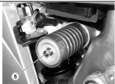
The rear suspension consists of a spring and shock-absorber group, linked to the frame via silent-block and the rear fork levers. To adjust the setting, the shock absorber has one set screw to adjust rebound damping, one set screw «2» to adjust compression damping, a ring nut for preloading adjustment of spring «3» and a ring nut «4».
REAR SHOCK ABSORBER ADJUSTMENT
The standard setting of the rear shock absorber is adjusted so as to satisfy all main high and low speed riding conditions, both with reduced and full vehicle load. It is at any rate possible to insert personal settings, depending on vehicle utilization.
TO COUNT THE NUMBER OF RE-LEASES AND/OR REVOLUTIONS OF ADJUSTMENT SETTINGS (1 - 2) ALWAYS START FROM THE MOST RIGID SETTING (WHOLE CLOCKWISE ROTATION OF THE SETTING). DO NOT FORCE THE ROTATION OF ADJUSTMENT SETTINGS (1 - 2) BEYOND THE END OF THE STROKE IN BOTH DIRECTIONS, IN ORDER TO AVOID ANY DAMAGE
ATTENTION

POUR COMPTER LE NOMBRE DE CRANS ET/OU TOURS DES RÉGULATEURS (1 - 2), PARTIR TOUJOURS DE LA CONFIGURATION LA PLUS RIGIDE (ROTATION COMPLÉTE DU RÉGULATEUR DANS LE SENS DES AIGUILLES D'UNE MONTRE). NE PAS FORCER LA ROTATION DES RÉGULATEURS (1 - 2) AU-DELÀ DE LA FIN DE COURSE DANS LES DEUX SENS, POUR ÉVITER D'EVENTUELS ENDOMMAGEMENTS.
03_05
Using the appropriate wrench, slightly unscrew the locking ring nut (4).
- Turn the adjustment ring nut «3» to adjust preloading of the «B» spring.
- When the optimal adjustment level has been achieved, screw in the locking ring nut «4» completely.
Work on the ring nut (2), to regulate the shock absorber compression damping at low speeds (see table).
Work on the knob (6), to regulate the shock absorber compression damping at high speeds (see table).
STANDARD ADJUSTMENT OF REAR SUSPENSION
| Shock absorber center to center distance (A) | 18.6 ± 0.06 in (473 ± 1.5 mm) |
| Length of (preloaded) (B) spring | 9.7 in (247 mm) |
| Rebound adjustment, screw (1) | 23 click |
| Compression adjustment, screw (2) | Completely open |
| By-pass adjustment knob (6) | Completely open (-) |
RéGLAGE STANDARD DE LA SUSPENSION ARRIÈRE
Front fork adjustment (03_06, 03_07)
The front suspension consists of a hydraulic fork connected to the headstock by means of two plates. To adjust the vehicle's setting, each fork stem is equipped with an upper screw (1) to adjust rebound damping and with a lower screw (2) to adjust compression damping.
FRONT FORK ADJUSTMENT
IMPORTANT
DO NOT STRAIN THE ROTATION OF ADJUSTMENT SETTINGS (1 . -2) BEYOND THE END OF THE STROKE IN BOTH DIRECTIONS, IN ORDER TO AVOID ANY DAMAGE SET BOTH STEMS WITH THE SAME SPRING PRELOAD AND DAMPING TOLERANCES: RIDING THE VEHICLE WITH A DIFFERENT ADJUSTMENT FOR THE TWO STEMS REDUCES ITS STABILITY. IF YOU INCREASE SPRING PRELOAD, YOU ALSO NEED TO INCREASE REBOUND DAMPING, IN ORDER TO AVOID SUDDEN JERKS DURING RIDING.
The standard setting of the front fork is adjusted so as to satisfy all main high and low speed riding conditions, both with reduced and full vehicle load. It is at any rate possible to insert personal settings, depending on vehicle usage.
Standard front suspension adjustment:
- Hydraulic rebound adjustment, screw (1) from completely closed () open (* 12 clicks
- Hydraulic compression damping adjustment, screw (2) from completely closed () open (^) 12 clicks
Hub sprongs (A) (^**) from the upper plate (cap excluded): 1 notch.
(^*) = Clockwise
(^**) = Counterclockwise
(^**) = Only use an Official aprilia Dealership for this type of adjustment
IMPORTANT
TO COUNT THE NUMBER OF RE-LEASES AND/OR REVOLUTIONS OF ADJUSTMENT SETTINGS (1 - -2) ALWAYS START FROM THE MOST RIGID SETTING (WHOLE CLOCKWISE ROTATION OF THE SETTING).
IMPORTANT

SPORT SETTINGS MAY BE USED ONLY FOR OFFICIAL COMPETITIONS TO
BE CARRIED OUT ON TRACKS, AWAY FROM NORMAL ROAD TRAFFIC AND WITH THE AUTHORIZATION OF THE RELEVANT AUTHORITIES. USING SPORT SETTINGS AND RIDING THE VEHICLE ON ROADS AND MOTORWAYS WITH THESE SETTINGS IS STRICTLY FORBIDDEN.
ATTENTION

LES RÉGLAGES POUR UNE UTILISATION SPORTIVE DOIVENT ÉTRE EFFECTUÉS EXCLUSIVÉMENT À L'OCASION DE COURSES ORGANISÉES OU D'ÉVENEMENTS SPORTIFS À SE DISPUTER SUR DES CIRCUITS ISOLES DE LA CIRCULATION ROUTIÈRE ET AVEC L'ACCORD DES AUTORITÉS COMPÉTENTE. IL EST STRICTEMENT INTERDIT D'ÉFFECTUER DES RÉGLAGES POUR UNE UTILISATION SPORTIVE ET DE CONDUIRE LE VEHICULE AVEC UNE TELLE ASSIETTE SUR LES ROUTES ET LES AUTOROUTES.
Running-In
Engine running-in is essential to preserving engine life and performance over time. Twisty roads and gradients are ideal to run in the engine, brakes and suspensions effectively. Vary your driving speed during the run-in. In this way, you allow for the work of components to be "loaded" and then "unloaded", thus cooling the engine parts. Even if it is important to "stretch" engine components during the running-in, make sure not to strain them.
Rodage
Follow the guidelines detailed below:
- Do not accelerate suddenly and completely when the engine is running in a low gear, either before or after running-in.
for the first 3 hours of operation, do not exceed 50% of the travel of the accelerator and never exceed 8,000 rpm,
for the next 12 hours, do not exceed 75% of the travel of the accelerator
NOTE
EVEN AFTER THE RUNNING-IN PERIOD, AVOID RUNNING THE ENGINE TO TOP SPEED, WHEN THE LIMITER CUTS IN:
RXV 450 11500 rpm
RXV 550 11000 rpm
IMPORTANT
THE WARNING LIGHT OF THE LIMITING DEVICE (NOT THE ELECTRONIC CENTRAL UNIT) IS SET, AT THE TIME OF PRODUCTION, TO 8000 RPM.
As with any high performance engine, the proper starting procedure is to be known and utilized each time the motorcycle is started. The RXV 4.5 and 5.5 models are equipped with a fast idle knob that when engaged, raises the engine's idle RPM for cold starting and engine warm up. It is important to understand completely how to engage and disengage this feature prior to starting the motorcycle.
Get onto the bike in riding position.
Make sure that the stand has been retracted completely.
Make sure that the light switch (1) is positioned to low beam lights.
- Turn the engine stop switch 2 to RUN.
- Turn the key to set the ignition switch to «ON».
- the ignition screen is displayed on the dashboard for three seconds.
- All instrument panel lights come on for three seconds.
Arrive a ce point :
- Verify that the green neutral light is illuminated green.
- Press the starter button «3», holding it in until the engine starts.
IMPORTANT
DO NOT APPLY ANY THROTTLE WHEN STARTING.
NEVER PLACE THE MOTORCYCLE IN GEAR OR RIDE THE MOTORCYCLE WITH THE FAST IDLE KNOB PULLED OUT AND LOCKED IN THE FAST IDLE POSITION. SERIOUS INJURY, OR LOSS OF LIFE, MAY RESULT IF THE MOTORCYCLE IS RIDEN WITH THE FAST IDLE KNOB ENGAGED AND THE ENGINE IDLING AT AN RPM HIG-ER THAN THE STANDARD SPECIFICATION.
Démarrage à froid:
Pull out the fast idle knob and rotate 90 degrees to lock in place.
- Turn on the ignition key.
- Verify that the neutral light is illuminated, confirming the motorcycle is not in gear. If the green neutral light is not illuminated, operate the shift level up, or down, to locate the neutral position. Recheck that the neutral light is illuminated green.
- Do not apply any throttle.
- Press the starter button, holding it down until the engine starts. If the engine does not start after 5 to 7 seconds of cranking, turn the ignition key off, then back on and retry starting the engine.
- Once the engine starts, allow the fast idle knob to hold the idle at the higher RPM.
After approximately 30 to 60 seconds (until the engine begins to warm) turn the fast idle knob off by pulling out and turning 90 degrees, allowing it to return to its normal "off" position.
The motorcycle should idle on its own at approximately 2,000 RPM. If it does not, pull the fast idle knob out for an additional 20 to 30 seconds, allowing for additional warm up time.
Démarrage à froid:
Stopping the engine (03_13)
It is very important to select an appropriate parking spot, in compliance with road indications and the guidelines described below.
To park the vehicle:
- Select an appropriate parking spot.
- Stop the vehicle.
- Set the engine stop switch «1» to «OFF»
. Turn the key and set the ignition switch «2»
to
Get off the vehicle.
- Place the vehicle on the stand.
- Block the steering and take out the key.
To place the vehicle on the stand:
- Grasp the left grip «1» and put the right hand on the upper rear part of the vehicle «2».
- Push the side stand fully down with your right foot «3».
- With the stand fully extended, lean the vehicle to the side until the stand rests on the ground.
- Turn the handlebar fully to the left.
IMPORTANT
MAKE SURE THAT THE GROUND WHERE YOU HAVE PARKED THE VEHICLE IS FREE FROM OBSTACLES, FIRM AND LEVEL.
Bequille (03_14)
The following instructions refer to normal use of your vehicle, and should be re
Une conduite sure (03_15, 03_16, 03_17, 03_18, 03_19, 03_20, 03_21, 03_22, 03_23, 03_24, 03_25, 03_26, 03_27, 03_28, 03_29, 03_30, 03_31, 03_32, 03_33, 03_34, 03_35, 03_36, 03_37)
RÉGLES FONDAMENTALES DE SECURITÉ
spected. Observing these rules will allow you to increase your level of safety and that of those around you, as well as increasing the life and usefulness of your vehicle. Obviously two-wheeled vehicles do not offer any of the protection normally given by an automobile. For this reason, it is fundamental to wear the appropriate protective clothing. In particular, while riding your vehicle, you should always wear a helmet, gloves, protective glasses, along with a heavy jacket, sturdy shoes, and long, hard-wearing pants. In any case, you should always bear in mind that even the best clothing and helmet can not protect you in case of a fall or collision with another vehicle. Protective clothing will protect you from scratches and abrasions, but their protective ability is minimal in the case of impact. Make sure you have all the requirements under local law, including driver's license, minimum age, adequate preparation, insurance, taxes, registration, license plate, etc. As soon as you receive your vehicle, familiarize yourself with it, practicing in an area with minimal traffic. Avoid riding your vehicle in areas with high levels of traffic until you have obtained an optimum level of experience and are completely sure of your riding skills. While this vehicle is sanctioned for use on highways and county roads, it is recommended that you do not ride on these types of streets until you have obtained a high level of familiarity with your vehicle and have a high level of ability in its use. A new vehicle must undergo a thorough run-in. Before you start
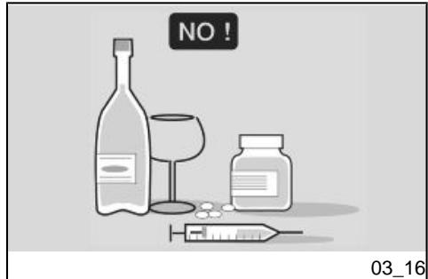
up the engine, make sure that the brakes, clutch, transmission and throttle lever all work properly, and that the gasoline and oil levels are appropriate. The exhaust system, brakes and other components can become hot while riding. Do not touch these components. Taking some medicines or drugs, either under a doctor's prescription or illegally, as well as drinking alcohol, increases the risk of an accident notably. Do not ride under the effect of alcohol or medicine, whether they are illegal or prescribed by a doctor. Make sure that your physical condition is appropriate before you begin to ride your vehicle. Do not ride if you are particularly fatigued or tired. Alcohol, medicine, and tiredness are the principal causes of accidents. Many accidents are due to the rider's inexperience. Do not ride your vehicle before you have attended training held by a recognized organization such as the Motorcycle Safety Foundation. Always remember that riding a two-wheeled vehicle, while easy and fun, is very different from driving a car. An expert driver is not necessarily capable of riding a two-wheeled vehicle safely. NEVER lend your vehicle to other people if you are not sure that they are experts, and have a driver's license. Respect all the rules of the road. In particular, pay at
tention to all warning, traffic and informational signs.
Avoid showing off with dangerous moves (for example wheelies). In particular, respect speed limits, and remember that road conditions vary based on weather conditions: wet and icy roads are particularly dangerous at sustained speeds. Automobile drivers frequently have difficulty seeing two-wheeled vehicles, so you should always give cars precedence, even if cases where the rules of the road actually give you the right of way. Always make sure that the road is free behind you before changing lanes. Do not rely exclusively on your rearview mirror, since it may underestimate the distance and/or speed of a vehicle, or even not show it at all. Avoid obstacles that may damage your vehicle or make you lose control. Do not drive immediately behind vehicles, either trucks or cars, and do not drive in their wake in an attempt to increase your
speed. In the case of an accident, motorcycles and scooters do not offer the same level of protection given by automobiles. The legs are especially at risk of injury. Installing leg-guards can greatly increase the risk and seriousness of injuries in the case of an accident. Do not install legguards available on the spare part and accessory after market. Not following these recommendations could lead to serious injury and even death. While driving always keep both hands on the handlebar and both feet on the footrests. Never change gear without using the clutch if the vehicle is provided with it. Do not use the gear shift or other handles jerkily or suddenly. Driving in this manner could damage the internal components of the vehicle, leading to the engine seizing, loss of control, serious injury, or even death. Remain seated while riding. Never stand on your feet or stretch yourself while riding. If you need to rest, pull over in a safe place on the road. It is very important for your safety that you always ride with the utmost attention. Pay attention to your actions, do not allow yourself to be distracted by other cars, people or things near the street, etc. Do not smoke, eat, drink, read, etc., while riding. If it becomes necessary to examine a road map, pull over and do so safely. Use only the fuel and lubricants indicated safe for your vehicle in the TABLE OF RECOMMENDED PRODUCTS; check the level of coolant, fuel and oil regularly. If the throttle grip is blocked, you could fall or have a collision with another vehicle. If
the throttle grip is blocked, turn of the engine with the engine stop button located on the right handle. Do not attempt to restart the engine until the throttle grip has been repaired and is completely functional. Not observing these warnings may lead to a fall resulting in serious injury and even death.
IMPORTANT
IN THE CASE OF AN EMERGENCY BECAUSE THE THROTTLE GRIP IS BLOCKED, ALWAYS TURN OF THE ENGINE USING THE ENGINE STOP BUTTON LOCATED NEAR THE ACCELERATION GRIP ON THE RIGHT HANDLEBAR. NEVER USE THE VEHICLE IF THE THROTTLE GRIP DOES NOT AUTOMATICALLY AND COMPLETELY RETURN TO THE NEUTRAL POSITION WHEN YOU LET GO OF IT ON. CONTACT YOUR LOCAL OFFICIAL aprilia DEALERSHIP FOR REPAIRS. NOT OBSERVING THESE WARNINGS MAY LEAD TO SERIOUS
If you are involved in an accident with your vehicle, make sure that the command levers, tubes, wires, braking system and other vital components were not damaged. If your vehicle is involved in an accident, immediately contact your local aprilia Dealership which has the tools and knowledge necessary to assess if any damages were sustained that could compromise your safety.
Your aprilia Dealership is able to resolve all safety problems, on the condition that you tell them about all mechanical malfunctions.
Do not use the vehicle when it is damaged. A damaged vehicle could lose stability or have other problems which may increase the risk of accidents, and consequently the risk of serious injuries or even death.
Do not attempt to modify the position, angle or color of your license plate. The license plate should not be covered in any way, not even with transparent plas
tic. Do not modify your vehicle's safety systems, in particular components associated with the turn signals, rearview mirrors, the lights and the horns.
Any modification to the vehicle renders the warranty null and void.
Do not modify the engine in order to increase its power. This could lead to irreparable damage to the engine, including compromising its performance and the manageability of the vehicle, leading to a fall, serious injuries, and even death.
To repair your vehicle use only original aprilia parts or parts approved by aprilia. The use of aftermarket accessories and spare parts can seriously compromise the safety of your vehicle, as well as its performance and usability. All modifications that impact the performance and safety of the vehicle render the warranty null and void.
Tampering with the emissions or sound control system is prohibited by law and can be severely punished.
In some jurisdictions your vehicle could be confiscated.
This vehicle was not designed to carry a sidecar, nor to be used to haul trailers or other vehicles.
aprilia does not produce sidecars or trailers, and for this reason is not able to predict the consequences that these accessories could have on the stability and
maneuverability of your vehicle: in any case you are advised that these may have a negative effect on your vehicle, and the warranty will not be recognized for any damages the vehicle or its components may sustain due to a use of this type of accessory.
Never use your vehicle to race other vehicles.
When braking use both the front and rear brake. In the case of abrupt braking, the use of only one brake could cause your vehicle to slide or cause you to lose control of the vehicle.
While driving downhill, take advantage of the engine's braking action by selecting the same gear or a lower gear in respect to that used for going uphill. Use the front and rear brakes with moderation.
Always travel at an appropriate speed and avoid sudden useless acceleration, not only to increase your safety, but also to reduce fuel consumption, and increase your vehicle's life.
When you ride your vehicle on wet or slippery roads, always remember that your traction is notably diminished. In these conditions always maneuver your vehicle with the maximum caution and care.
Sudden acceleration, brakes or turns could cause you to lose control of your vehicle. When traction is reduced, accelerate and brake taking advantage of, as
much as possible, the engine's braking power. Avoid braking suddenly and/or too quickly.
Open and close the throttle grip slowly in order to avoid causing the rear wheel to slip or slide.
Slow down and drive with caution on irregular road surfaces.
Avoid turning the throttle grip to its maximum except in cases of absolute necessity, such as passing.
Do not let the engine run "stressed," running at an RPM that is too low. Shift down to a lower gear. Do not make the engine run at too high an RPM. Pay attention to the red line on the speedometer.
Remember that turning too aggressively can cause the side of the tires to lose contact with the ground, leading to a fall, serious injury, and even death.
Always respect speed limits, remembering that it is not always safe to ride at the maximum of the limits under all road conditions. Slowing down slightly greatly increases your safety under all road conditions.
Do not drive the vehicle off-road.
Do not tamper with the exhaust or emissions control system, not only because it
could harm the environment, but also because you could risk penal sanctions.
Before you begin riding, make sure that your clothing is in good condition. Wear your helmet correctly, making sure that the visor or your protective goggles are clean.
Research and experience demonstrate that drivers of other vehicles frequently do not see scooters and motorcycles. To render yourself more visible to these driv
VÉTEMENTS
ers, wear reflective clothing such as reflective jackets, or other types of clothing with reflective areas sewn on to the jacket, pants and gloves. Pay particular attention to trucks and automobiles arriving from the other side of the road, as they could turn right or left right in front of you. Many accidents are caused by a driver on the other side of the road who turns left without taking into consideration the vehicle in front.
Without doubt the driver in front of you will swear that s/he saw you only when, after turning,s/he found you in their lane. Ride with caution!
Wear protective clothing, choosing bright and/or reflective colors. This will make you easily seen by other road users, thus reducing the risk of an accident an increasing your protection level in the event of a fall.
Always wear a helmet. Head injuries cause many accidents to become mortal.
Clothing must be particularly tight and closed around wrists and ankles. Cords, belts, and ties should not dangle; prevent these and other objects from interfering with your ride, getting caught in moving parts or driving mechanisms.
Do not keep objects that could become dangerous in a fall from your pocket, such
as keys, pencils, etc. Make sure that any passengers also follow these guidelines.
The owner of the vehicle is responsible for the choice, installation and use of all accessories.
The installation of inappropriate accessories or overloading the vehicle could render it unstable and cause accidents, with the consequent risk of serious injury and even death. Windshields are particularly dangerous in the case of accidents, because they can break and injure or cut the driver. In case of doubt about any accessory or installation or any freight to be carried, it is recommended that you first consult your local aprilia Dealership.
Do not install any accessory that covers the horn or the lights or impairs their operation, is in the way of suspension travel or steering angle, impairs the operation of vehicle controls or reduces ground clearance or lean-in angle.
Do not install accessories that hinder access to controls and may thus lengthen
ACCESSIONS
your response time in the event of an emergency.
Large fairings and windshields affect the vehicle's aerodynamic performance and its stability, especially at high speeds.
Make sure that anything mounted on the vehicle is attached securely, and cannot become loose, blocking wheels, forks, etc. Do not install electrical accessories, and do not modify the vehicle's electrical system. Any component that could cause an electrical surge or an electrical problem could lead to the immediate stopping of the vehicle, the lights and horn to turn off or lose intensity, and malfunctioning of the other safety features. Use only original aprilia accessories.
Do not overload the vehicle.
Secure bags and baggage as close to possible to the vehicle's center of balance and distribute the weight as uniformly as possible between the two sides, to reduce imbalance as much as possible. Always remember that the baggage will tend to loosen during the ride. For this reason, check frequently that your baggage is secure.
Never allow objects to hang from the handlebars of your vehicle, from the mudguards, or the forks, as this could compromise the maneuverability of your vehicle and impede your ability to avoid an accident. Not observing these warnings may lead to a fall, resulting in serious injury and even death.
Do not ride with a helmet attached to the belt, since in this position it could easily become entangled in the wheels, the mudguards or in the forks, causing a fall, and consequently, serious injury or even death.
Carry a passenger only if the vehicle is equipped with passenger footrests, passenger grab straps, and a passenger seat.
When you carry a passenger, always remember that the vehicle's manageability is reduced, the brakes are less efficient, and the center of gravity is higher and farther back.
CHARGE
This increases the possibility of the front wheel losing contact with the ground, especially while accelerating. For this reason, avoid abrupt accelerating and braking. Many accidents are caused by inexpert riders who are carrying a passenger. Remember to execute driving maneuvers with a greater allowance for safety in case of excessive passenger weight.
Avoid abrupt and excessive acceleration. Slow down in advance, and calculate distances for stopping and for longer maneuvers. Not following these instructions could lead to the vehicle overturning or other accidents with consequent serious injuries and even death.
Never transport objects that are not secure, and make sure that when they are transported they are securely fastened to the vehicle.
Do not carry packages that protrude from the luggage rack or which cover any of the alarm devices or lights.
Never carry animals or small children on the glove compartment or the luggage rack.
Never exceed the maximum weight indicated for each bag.
Overloading your vehicle can seriously decrease its stability and maneuverability leading to a fall, with consequent serious injury or even death.
Engine oil level (04_01, 04_02)
Checking and refilling engine oil
IMPORTANT

DO NOT SPILL OIL!
AVOID SPILLING OIL OVER COMPONENTS, THE AREA YOUR ARE WORKING IN AND ITS SURROUND. REMOVE ANY TRACE OF OIL CAREFULLY.
IN THE EVENT OF A LEAK OR MALFUNCTION, CONTACT AN Official aprilia Dealership
THIS TYPE OF VEHICLE HAS SEPARATE LUBRICATION CIRCUITS FOR ENGINE AND TRANSMISSION/CLUTCH. OIL LEVEL CHECK AND REPLACEMENT MUST BE CARRIED OUT FOR BOTH CIRCUITS.
IMPORTANT
ENGINE OIL MUST BE CHECKED WHEN THE ENGINE IS WARM. IF YOU CHECK ENGINE OIL LEVEL WHEN
- Hold the vehicle level with the two wheels on the ground.
- Check the oil level
using the relevant transparent dipstick 1 .
MAX = maximum level
MIN = minimum level
Add fluid as required:
IMPORTANT
IF YOU RIDE THE VEHICLE IN A SPORTY FASHION, SOME OIL SPLATTER MAY GET TO THE AIR FILTER HOUSING THROUGH THE ENGINE VENT.
IMPORTANT

DO NOT GO BEYOND THE MAX AND MIN LEVEL MARK TO AVOID SEVERE ENGINE DAMAGE.
Engine oil change (04_03, 04_04, 04_05, 04_06)
- Park the vehicle on solid, level ground.
- Place the vehicle on the stand.
Gearbox oil level (04_07, 04_08, 04_09, 04_10)
- Remove the refilling cap (3).
- Pour in the new oil, until the mark on the inspection cap is reached (2).
IMPORTANT

DO NOT ADD ADDITIVES OR OTHER SUBSTANCES TO THE LIQUID.
IF YOU USE A FUNNEL OR ANOTHER IMPLEMENT, MAKE SURE THAT THEY ARE PERFECTLY CLEAN.
- Wait several minutes to allow the oil to flow from the clutch to the transmission. Then check the oil level again.
REPLACEMENT
NOTE
USE THE OIL RECOMMENDED IN THE PRODUCT CHART
NOTE
TO ENSURE EASIER AND FULL OIL DRAINAGE THE OIL MUST BE HOT AND THEREFORE MORE FLUID.
Si nécessaire :
Lower the oil pan guard.
- Place a container of adequate capacity under the drainage cap (4).
- Unscrew and remove the drainage cap (4).
- Unscrew and remove the refilling cap (3).
- Drain the oil and let it drip for a few minutes into the container below.
- Check, and if necessary, replace the washers from the drainage cap (4).
- Screw in and lock the drainage cap (4).
- Remove the rear brake lever, unscrewing the screw (1) and holding on to the washer.
- Unscrew and remove the inspection cap (2).
- Pour in the new oil, until the mark on the inspection cap is reached (2).
- Wait several minutes to allow the oil to flow from the clutch to the transmission.
- Then check the oil level again.
- Tighten the refilling cap (3).
IMPORTANT
THE OIL FLOW FROM THE CLUTCH TO THE TRANSMISSION AND FROM
This vehicle is fitted with tires with inner tubes (Tube type).
Les pneus
Minimum tread depth:
front and rear 0.079 in (2 mm) USA 0.118 in (3 mm) and in any case no less than that prescribed by law in the country where the vehicle is used.
Spark plug removal (04_11, 04_12, 04_13)
At regular intervals, remove the spark plug and clean off any carbon deposits or replace as required.
Depose de la bougie (04_11, 04_12, 04_13)
ALWAYS REPLACE BOTH SPARK PLUGS, EVEN IF ONLY ONE NEEDS REPLACING.
ATTENTION

MÉME SI UNE SEULE DES BOUGIES DOIT ÉTRE REMPLACÉE, REMPLACER TOUJOURS LES DEUX BOUGIES.
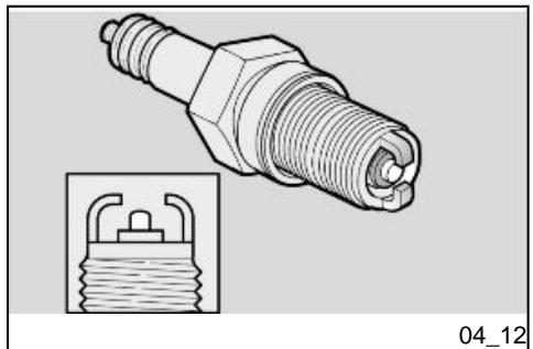
In order to gain access to the spark plugs:
IMPORTANT

BEFORE CARRYING OUT THE FOLLOWING STEPS, ALLOW THE ENGINE AND THE MUFFLER TO COOL DOWN UNTIL THEY REACH ROOM TEMPERATURE IN ORDER TO AVOID ANY BURNS.
- Place the vehicle on the stand.
NOTE

THE VEHICLE HAS A SPARK PLUG (2) FOR EACH CYLINDER. THE FOLLOWING STEPS RELATE TO JUST ONE SPARK PLUG BUT APPLY TO BOTH.
- Remove the pipette (1) from the spark plug (2).
- Remove any sign of dirt from the spark plug base (2).
- In the hexagonal housing of the spark plug (2), insert the fork wrench included in the tool kit.
- Unscrew the spark plug (2) and remove it from the housing, taking care not to allow any dust or other substances to get inside the cylinder.
Checking and cleaning:
- Check that the electrodes and spark plug (2) insulator do not show traces of carbon deposits and or corrosion. If required, clean them using a jet of compressed air.
If the spark plug (2) shows cracks on the insulator, corroded electrodes, excessive deposits, or if the top of the central electrode has become rounded, the spark plug must be replaced.
IMPORTANT

USE RECOMMENDED SPARK PLUGS ONLY. USING A SPARK PLUG OTHER THAN SPECIFIED MIGHT COMPROMISE ENGINE PERFORMANCE AND LIFE. TO CHECK THE GAP BETWEEN THE ELECTRODES, USE A FEELER GAUGE.
- Checking the gap between the electrodes with a feeler gauge.
IMPORTANT

DO NOT ATTEMPT TO READJUST THE GAP BETWEEN THE ELECTRODES.
Characteristic
Electrode gap
$$ 0. 0 2 7 \pm 0. 0 3 1 \text {i n} (0, 7 \pm 0, 8 \mathrm {m m}) $$
If the gap between the electrodes is not what is recommended, then replace the spark plug (2).
Make sure the washer is in good conditions.
Installation:
- Manually screw in the spark plug (2) to avoid damaging the thread.
- Tighten using the wrench supplied in the tool kit turning each spark plug (2) by 1/2 turn to compress the washer.
- Insert the electrical connection to the spark plug (1) correctly so that it does not detach as the engine vibrates.
ATTENTION

LA BOUGIE (2) DOIT ETRE BIEN VISSE, AUTREMENT LE MOTEUR POURRAIT SURCHAUFFER ET S'ENDOMMAGER GRAVEMENT.
Couples de blocage (N^*m)
Bougie - E.-U.
8,85 pi-lb (12 Nm)
Air filter removal (04_14, 04_15, 04_16, 04_17, 04_18, 04_19)
- Remove the saddle.
- Raise the tank.
- Release the air filter cover by gripping and lifting the handles from both sides.
- Slide out the air filter housing cover from behind, complete with filter.
Demontage du contrôle a air (04_14, 04_15, 04_16, 04_17, 04_18, 04_19)
IN THE EVENT OF A FALL, CLEAN THE AIR FILTER AND ITS HOUSING CAREFULLY, REMOVING ANY TRACES OF OIL WHICH MAY HAVE ENTERED FROM THE OIL TANK THROUGH THE OIL EXHAUST PIPES.
N.B.
DURANT LE REMONTAGE, PRÉTER ATTENTION AU NETTOYAGE PARFAIT DU BOITIER DU FILTR. ENLEVER Toute TRACE DE SALETE POUVANT ENTRE R LORS DE LA DÉPOSE. DURANT LE REMONTAGE, PRÉTER ATTENTION À L'INTRODUCTION CORRECTE DES PRISES D'AIR.
ATTENTION

PRÉTER ATTENTION AU FIL DE RETENUE DU RÉSEROVIR ET NE TOUCHER SOUS AUCUN PRÉTEXTE LE PÔLE POSITIF DE LA BATTERIE.
ATTENTION

EN CAS DE CHUTE, NETTOYER SOIGNGENCEMENT LE FILTRÉ À AIR ET LE BOITIER DU FILTRÉ À AIR DE L'HUILÉ ÉVENTUELLEMENT ENTREE DANS LE RÉSEROIR D'HUILÉ À TRAVERS LE RENIFLARD DES VAPEURS D'HUILÉ.
IMPORTANT

REMOVE THE AIR FILTER COVER ONLY WHEN THE VEHICLE IS PERFECTLY CLEAN TO AVOID GETTING ANY TRACES OF DIRT IN THE HOUSING.
ATTENTION

EFFECTUER L'OPÉRATION DE DÉPOSE DU COUVERCLE DU FILTRÉ À AIR SEULEMENT UNE FOIS LA MOTO PARFAIEMENT NETTOYÉE POUR ÉVITER QUE DES SALETÉS N'ENTRENT DANS LE BOITIER DU FILTRÉ.
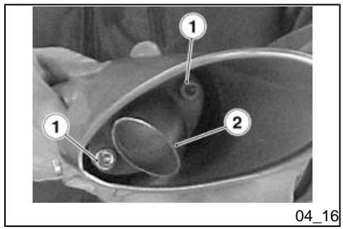
SPARK ARRESTER
- Unscrew and remove the two fixing screws (1) on the closure cap (2).
SPARK ARRESTER
- Clean or replace the metal mesh screen (3), if it is damaged.
Do not use the vehicle if the coolant is below the minimum level.
COOLANT IS TOXIC WHEN INGESTED; CONTACT WITH EYES OR SKIN MAY CAUSE IRRITATION. IN THE EVENT OF CONTACT WITH THE EYES OR THE SKIN, RINSE REPEATEDLY WITH PLENTY OF WATER AND SEEK MEDICAL ADVICE. IN THE EVENT OF INGESTION, INDUCE VOMITING, RINSE MOUTH AND THroat WITH ABUNDANT WATER AND SEEK MEDICAL ADVICE IMMEDIATELY.

LE LIQUIDE DE REFROIDISSEMENT EST TOXIQUE SI INGÉRÉ ; LE CONTACT AVEC LA PEAU ET LES YEUX POURRAIT CAUSER DES IRRITATIONS. SI LE LIQUIDE ENTRE EN CONTACT AVEC LA PEAU OU LES YEUX, RINCER LONGUEMENT ET ABONDAMMENT À L'EAU ET CONSULTER UN MÉDECIN. SI INGÉRÉ, PROVOUER LE VOMISSEMENT, RINCER ABONDAMMENT À L'EAU LA BOUCHE ET LA GORGE ET CONSULTER IMMEDIATIMENT UN MÉDECIN.
Coolant liquid solution is 50% water and 50% antifreeze.
This is the ideal mixture for most operating temperatures and provides good corrosion protection.
This solution is also suited to the warm season, as it is less prone to evaporative loss and will reduce the need for refills.
Less water evaporation means fewer mineral salts depositing in the radiators, which helps preserve the efficiency of the cooling system.
When the temperature drops below zero degrees centigrade, check the cooling system frequently and add more anti-freeze if needed (up to 60% max.).
Use distilled water in the coolant mixture to avoid damaging the engine.
IMPORTANT

DO NOT REMOVE THE RADIATOR CAP 1 WHEN THE ENGINE IS HOT, BECAUSE THE COOLANT IS UNDER PRESSURE AND VERY HOT CONTACT WITH SKIN OR CLOTHES MAY CAUSE SEVERE SCALDING AND/OR DAMAGES.
Checking and refilling
- If required, add coolant until the radiator plates are covered. Do not exceed this level, otherwise the coolant will spill during engine operation. If you use a funnel or another implement, make sure that it is perfectly clean.
- Reinsert the radiator cap (1).
IMPORTANT
IN THE EVENT OF EXCESSIVE COOLANT CONSUMPTION, CHECK COOLING SYSTEM FOR LEAKS.
FOR REPAIR TAKE YOUR VEHICLE TO AN Official aprilia Dealership.

NE PAS AJOUTER D'ADDITIFS OU D'AUTRES SUBSTANCES AU LIQUIDE.
SI UN ENTONNOIR OU AUTRE ÉLÉMENT EST UTILISÉ, S'ASSURER QU'IL EST PARFAITEMENT PROPRE.
Check the brake fluid level according to the indications provided in the scheduled maintenance table.
The information provided below relates to an individual braking system but is applicable to both.
NOTE
THIS VEHICLE IS EQUIPPED WITH FRONT AND REAR DISC BRAKES, EACH OPERATED BY AN INDEPENDENT HYDRAULIC CIRCUIT.
IMPORTANT

SUDDEN CHANGES IN THE BRAKE LEVER'S TRAVEL OR ELASTIC RESISTANCE ARE DUE TO A MALFUNCTION OF THE HYDRAULIC CIRCUIT. IF YOU ARE IN DOUBT ABOUT THE CORRECT OPERATION OF THE BRAKING SYSTEM OR UNABLE TO CARRY OUT ROUTINE CHECK PROCEDURES CONTACT AN Official aprilia Dealer.
IMPORTANT

OR LUBRICATED, PARTICULARLY AFTER MAINTENANCE AND CHECK PROCEDURES HAVE BEEN CARRIED OUT.
CHECK THAT BRAKE WIRES ARE NOT TWISTED OR WORN.
ENSURE THAT WATER OR DUST DO NOT INADVERTENTLY GET INTO THE CIRCUIT.
IT IS ADVISIBLE TO WEAR LATEX GLOVES WHEN SERVICING THE HYDRAULIC CIRCUIT.
THE BRAKE FLUID MAY CAUSE IRRITATION IF IT COMES INTO CONTACT WITH SKIN OR EYES.
IMPORTANT

RINSE CAREFULLY ALL BODY PARTS WHICH HAVE COME INTO CONTACT WITH THE FLUID AND, SHOULD THE FLUID COME INTO CONTACT WITH THE EYES, SEEK MEDICAL ADVICE OR CONTACT AN OPHTHALMOLOGIST.
IMPORTANT

DO NOT DISPERSE THE FLUID IN THE ENVIRONMENT.
ATTENTION

PRÉTER UNE ATTENTION PARTICULIERÉ À CE QUE LES DISQUES DE FREIN NE SOIENT PAS GRAISSÉS, SPEÇALEMENT APRES L'EXÉCUTION D'OPÉRATIONS D'ENTRETIEN OU DE CONTROLE.
CONTROLER QUE LES TUYAUX DES FREINS NE SONT PAS ENTORTILLÉS OU USÉS.
FAIRE ATTENTION à CE QUE L'EAU OU LA POUSSIÈRE N'ENTRENT PAS ACCIDENTELLEMENT À L'INTÉRIEUR DU CIRCUIT.
AU COURS DES INTERVENTIONS D'ENTRETIEN SUR LE CIRCUIT HYDRAULIQUE, IL EST CONSEILLÉ DE PORTER DES GANTS EN LATEX.
LE LIQUIDE DE FREIN POURRAIT CAUSER DES IRRITATIONS S'IL VENAIT EN CONTACT AVEC LA PEAU OU AVEC LES YEUX.
ATTENTION

LAYER SOIGNEUSEMENT LES PARTIES DU CORPS ENTREES EN CONTACT AVEC LE LIQUIDE, S'ADRESSER À UN OCULISTE OU À UN
IMPORTANT

KEEP OUT OF REACH OF CHILDREN
IMPORTANT

WHEN YOU USE THE BRAKE FLUID, MAKE SURE NOT TO SPILL IT ONTO PLASTIC OR PAINTED COMPONENTS AS IT WILL DAMAGE THEM BEYOND REPAIR.
MÉDECIN SI DU LIQUIDE EST ENTRÉ EN CONTACT AVEC LES YEUX.
ATTENTION

NE PAS RÉPANDRE LE LIQUIDE DANS L'ENVIRONNEMENT.
ATTENTION

TENIR HORS DE PORTÉE DES ENFANTS.
ATTENTION

EN UTILISANT LE LIQUIDE DE FREIN, FAIRE ATTENTION À NE PAS EN RENVERSER SUR LES PARTIES EN PLASTIQUE ET PEINTES, CAR CELA LES ENDOMMAGERAIT IRRÉMÉDIABLEMENT.
Disc brakes
Freins à disque

THE BRAKES ARE CRITICAL TO YOUR SAFETY AND MUST ALWAYS BE KEPT IN PERFECT WORKING ORDER; CHECK THE BRAKES BEFORE EACH RIDE.
CHANGE OF THE BRAKE FLUID IS TO BE CARRIED OUT ACCORDING TO THE INDICATIONS IN THE SCHEDULED MAINTENANCE TABLE.
USE THE BRAKE FLUID SPECIFIED IN THE RECOMMENDED PRODUCTS TABLE.

LES FREINS SONT LES ORGANES
QUI GARANTISSENT PRINCIPALEMENT LA SECURITE, ILS DOIVENT DONC ETRE TOUJOURS MAINTENUS EN PARFAIT ETAT D'EFFICACITE;
LES CONTROLER AVANT CHAQUE VOYAGE.
EFFECTUER L'OPÉRATION DE REMPLACEMENT DU LIQUIDE DE FREIN SUR LA BASE DU TABLEAU D'ENTRETIEN PROGRAMME.
UTILISER DU LIQUIDE DE FREIN DUTYPE SPECIFIÉ DANS LE TABLEAU DES PRODUITS CONSEILLÉS.
Brake fluid decreases gradually in the reservoir as the brake pads wear down, to compensate for wear automatically.
The front brake reservoir (1) is found near the front brake lever connection.
The rear brake fluid reservoir (2) is integrated in the brake pump fastened to the frame, on the right side, near the fork.
Check the brake fluid level in the reservoirs before setting off.
IMPORTANT

DO NOT RIDE IF THE BRAKING SYSTEM IS LEAKING.
- Place the vehicle in an upright position and keep the handlebar straight.
- Check that the liquid contained in the tank (1) exceeds the "MIN" mark.
MIN = minimum level
MAX = maximum level
If the fluid does not reach the MIN. mark
IMPORTANT
- Check the brake pads and discs for wear
If the pads and/or the disc do not need replacing, add fluid.
IMPORTANT
RISK OF BRAKE FLUID SPILLAGE. DO NOT PULL THE FRONT BRAKE LEVER WHEN THE SCREWS (3) ARE LOOSE OR, ESPECIALLY, WHEN THE BRAKE FLUID RESERVOIR COVER (4) IS REMOVED.
Using a short Phillips screwdriver remove the screws (3) from the brake fluid reservoir.
-
Lift up and remove the cover (4), including the screws (3) and the gasket (5).
-
Soulever etrirer le couvercle (4) muni des vis (3) et du joint (5).
IMPORTANT

TO AVOID SPILLING THE BRAKE FLUID DURING TOP-UP, DO NOT SHAKETHE VEHICLE. DO NOT ADD ADDI-TIVES OR OTHER SUBSTANCES TOTHE LIQUID. IF YOU USE A FUNNEL OR ANOTHER IMPLEMENT, MAKESURE THAT THEY ARE PERFECTLY CLEAN.
- Refill the reservoir «1» with the brake fluid, until you go beyond the MIN minimum level mark.
IMPORTANT

FILL TO MAX LEVEL MARK ONLY WHEN THE BRAKE PADS ARE NEW. IT IS ADVISIBLE NOT TO TOP UP TO THE MAX LEVEL MARK WHEN THE BRAKE PADS ARE WORN BECAUSE YOUR RISK SPILLING THE FLUID WHEN CHANGING THE BRAKE PADS.
CHECKING BRAKING EFFICIENCY.
WHEN THE BRAKE LEVER HAS EXCESSIVE PLAY OR IF YOU NOTICE A LOSS OF BREAKING, CONTACT AN APRILIA OFFICIAL DEALER. THE
ATTENTION

POUR NE PAS RÉPANDRE DE LIQUIIDE DE FREIN DURANT LE REMPLISSAGE, IL EST RECOMMANDÉ DE NE PAS SECOUER LE VÉHICULE. NE PAS AJOUTER D'ADDITIFS OU D'AUTRES SUBSTANCES AU LIQUIDE. SI UN ENTONNOIR OU AUTRE ÉLÉMENT EST UTILISÉ, S'ASSURER QU'IL SOIT PARFAITEMENT PROPRE.
- Keep the vehicle upright.
- Check that the liquid contained in the reservoir is higher than the MIN. mark.
MIN = minimum level
If the fluid does not reach the MIN. mark
IMPORTANT
- Check the brake pads and discs for wear
If the pads and/or the disc do not need replacing, add fluid.
Refilling
IMPORTANT
RISK OF BRAKE FLUID SPILLAGE. DO NOT PULL THE FRONT BRAKE LEVER WHEN THE SCREWS (6) ARE LOOSE OR, ESPECIALLY, WHEN THE BRAKE FLUID RESERVOIR COVER (7) IS REMOVED.
Using a wrench, unscrew the two screws (6) from the brake fluid reservoir (2).
IMPORTANT
AVOID PROLONGED EXPOSURE OF THE BRAKE FLUID TO THE AIR. THE BRAKE FLUID IS HYGROSCOPIC AND ABSORBS MOISTURE WHEN IS IN CONTACT WITH THE AIR. LEAVE THE BRAKE FLUID RESERVOIR «2» OPEN ONLY FOR THE TIME NEEDED TO COMPLETE THE REFILL PROCEDURE.
-
Lift up and remove the cover (7), including the screws (6) and the gasket (8).
-
Soulever etrirer le couvercle (7) muni des vis (6) et du joint (8).
IMPORTANT

TO AVOID SPILLING THE BRAKE FLUID DURING TOP-UP, DO NOT SHAKE THE VEHICLE. DO NOT ADD ADDI-TIVES OR OTHER SUBSTANCES TO THE LIQUID. IF YOU USE A FUNNEL OR ANOTHER IMPLEMENT, MAKE SURE THAT THEY ARE PERFECTLY CLEAN.
ATTENTION

POUR NE PAS REPANDRE DE LIQUIDE DE FREIN DURANT LE REMPLIS-SAGE,IL EST RECOMMANDE DE NE PAS SECOUER LE VEHICULE.NEPAS AJOUTER D'ADDITIFS OU D'AUTRES SUBSTANCES AU LIQUIDE.SI UN ENTONNOIR OU AUTRE ELEMENT EST UTILISE,S'ASSURER QU'IL SOIT PARFAITEMENT PROPRE.
- Remove the saddle.
- Unscrew and remove the negative wire fastening screw, keeping the washer.
Batterie (04_26, 04_27, 04_28)
WHEN A FUSE KEeps BLOWING FREQUENTLY, THERE MAY BE A SHORT CIRCUIT OR OVERLOADING. IN THIS EVENT, CONTACT AN aprilia Official Dealer.
ENDOMMAGER LE SYSTÉME ÉLECTRIQUE ET MÈME PROVOQUER UN INCENDIE, EN CAS DE COURT-CIRCUIT.
ATTENTION

QUAND UN FUSIBLE GRILLE FREQUEMMENT,IL EST PROBABLE QU'IL EXISTE UN COURT-CIRCUIT OU UNE SURCHARGE.DANS CE CAS, S'ADRESSER A UN concessionnaire officiel aprilia.
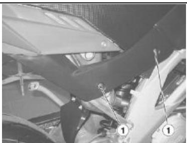
04_29
Checking the fuses is necessary whenever an electrical component fails to operate or is malfunctioning or when the engine does not start.
Check the auxiliary fuses first and then the main 30A fuse.
To check:
- Position the ignition switch to (OFF), in order to avoid an accidental short circuit.
- Remove the right side fairing, by removing the two screws (1) and lifting it out of its seat.
| (1) 7.5A fuse | Front headlights |
| (2) 7.5A fuse | ECU relay power |
| (3) 15A Fuse | ECU relay energizing |
| (4) 15A Fuse | Tailights, indicators, horn, instrument panel, stop light |
| (5) 7.5A fuse | Injector coils |
| (6) 7.5A fuse | Electric fan |
| (7) 5A fuse | Fuel pump |
DISPOSITION DES FUSIBLES SECONDAIRES
THREE FUSES FUSES<8>.
ARE
SPARE
N.B.
ARRANGEMENT OF MAIN FUSES
30A fuse
Battery recharge (there is just one fuse, the second one is a spare).
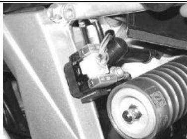
04_33
DISPOSITION DES FUSIBLES PRINCIPAUX
Fusible de 30 A
BEFORE CHANGING A BULB, CHECK THE FUSES.
Ampoules
N.B.
AVANT DE REMPLACER UNE AMPOULE, CONTROLLER LES FUSIBLES.

DO NOT USE THE VEHICLE IF THE LIGHTS ARE NOT WORKING PERFECTLY. DO NOT USE THE VEHICLE IF THE HEADLIGHT HAS NOT BEEN ADJUSTED AND IS NOT WORKING PERFECTLY. IT COULD TEMPORARILY FLASH AND BLIND ONCOMING VEHICLES, AND ALSO REDUCE YOUR ABILITY TO SEE OBSTACLES ALONG THE ROAD WHILE RIDING AT NIGHT.

NE PAS UTILISER LE VEHICULE SI LES FEUX NE FONCTIONNENT PAS PARFAITEMENT. NE PAS UTILISER LE VEHICULE SI LE FEU N'EST PAS CORRECTEMENT AJUSTÉ ET S'IL NE FONCTIONNE PAS À LA PERFECI-TION. CELA POURRAIT TEMPORAI-REMENT ÉBLOUIR ET AVEUGLER LES VEHUCULES EN APPROCHE, ET MÉME RÉDUIRE L'APTITUDE DU CONDUCTEUR À VOIR LES OBSTACLES LE LONG DE LA ROUTE DURANT LA CONDUITE DE NUIT.
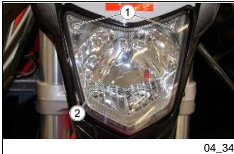
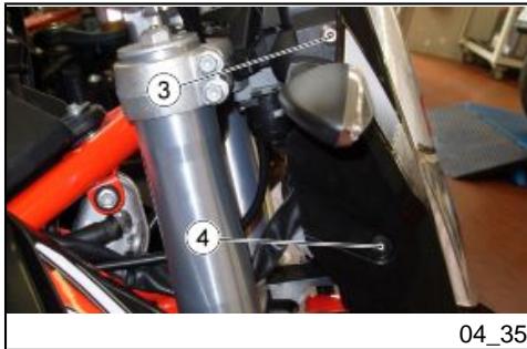
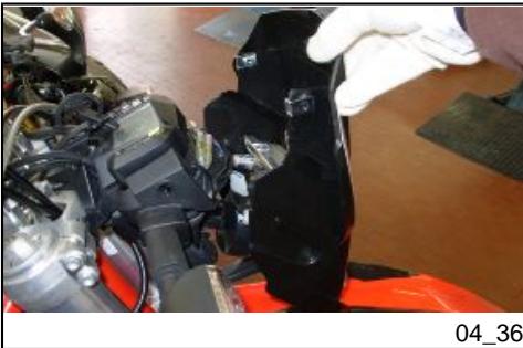
Front light group (04_34, 04_35, 04_36, 04_37, 04_38)
The front light contains:
Two parking light bulbs «1».
One highbeam/low beam bulb «2»
To replace:
- Place the vehicle on the stand.
- Working on both sides, unscrew the upper screw «3» and the lower screw with washer «4».
- Slide out the grill from the mud-flap housing.
Side light lamp «1»
- Slide out the parking light bulb and replace it with one of the same type.
High/low beam light bulb «2»
- Grasp the bulb connector «5», pull it out and disconnect it from the bulb housing.
- Slide out the casing «6» from the parabola housing and the bulb terminals.
- Unhook the two ends of the retaining spring (7), located in the bulb holder.
- Remove the bulb from its housing.
- Correctly install a bulb of the same type.
- Correctly place the casing «6» back inside, in the parabola housing and the bulb terminals.
- Connect the bulb connector «5».
A quick procedure to check the correct adjustment of the front light beam:
- Place the vehicle 10 meters from a vertical wall, making sure that the ground is level.
- Turn on the low beam light, sit on the vehicle and check that the light beam projected to the wall is a little below the headlight horizontal straight line (about 9/10 of the total height).
To set light beam height:
- Working on both sides, unscrew screw «1».
- Adjust the light until the desired positioning is found
- Working on both sides, screw in screw «1».
Front and rear disc brake (04_41, 04_42, 04_43, 04_44)
IMPORTANT

THE BRAKES ARE CRITICAL TO YOUR SAFETY AND MUST ALWAYS BE KEPT IN PERFECT WORKING ORDER; CHECK THE BRAKES BEFORE EACH RIDE. A DIRTY DISC SOILS THE PADS, LEADING TO LOSS OF BRAKING. DIRTY PADS MUST BE REPLACED, WHEREAS A DIRTY BRAKE DISC MAY BE CLEANED WITH A HIGH-QUALITY DEGREASING PRODUCT. HAVE THE BRAKE FLUID CHANGED AT AN Official aprilia Dealership ONCE A YEAR. USE THE BRAKE FLUID SPECIFIED IN THE RECOMMENDED PRODUCTS TABLE.
NOTE
THIS VEHICLE IS EQUIPPED WITH FRONT AND REAR DISC BRAKES, EACH OPERATED BY AN INDEPENDENT HYDRAULIC CIRCUIT.
The front braking system is single disc (left side).
The rear braking system is single disc (right side).
The information provided below relates to an individual braking system but is applicable to both.
Brake fluid decreases gradually in the reservoir (1-2) as the brake pads wear down, to compensate the wear automatically.
The front brake reservoir «1» is placed near the front brake lever connection. The rear brake fluid reservoir «2» is integrated in the brake pump fastened to the frame near the fork.
Check the brake fluid level in the reservoirs «1» «2» and check brake pads for wear before setting off.
Checking brake pads for wear
The rate at which the brake pads will wear depends on usage, riding style and road surface condition.
IMPORTANT

WEAR IS GREATER WHEN RIDING ON DIRTY AND WET ROADS, OR OFFROAD.
This is a quick inspection procedure to determine brake pad wear:
- Place the vehicle on the stand.
Check the front brake caliper pads:
- Visually inspect the area between brake disc and brake pads looking from the bottom up the front end;
Checking the rear brake caliper pads:
- Visually inspect the area between brake disc and brake
pads looking from the bottom up the rear end;
NOTE
IF BRAKE PADS WERE ALLOWED TO WEAR DOWN UNTIL UNCOVERING THE METAL SUBSTRATE, METAL-TOMETAL CONTACT WITH THE BRAKE DISC WOULD LEAD TO RATTLE AND THE BRAKE CALIPER SPARKING. THIS WOULD RESULT IN LOSS OF BRAKING AND BRAKE DISC DAMAGE, CAUSING A DANGEROUS RIDING CONDITION.
When the lining material of even just one of the brake pads is worn down to nearly 0.06 in (1.5 mm) (or even if one of the wear indicators is no longer visible), replace both brake pads.
IMPORTANT
FOR REPLACEMENT TAKE YOUR SCOOTER TO AN Official aprilia Dealership.
When storing the vehicle away for long periods, some precautions are necessary to avoid damage due to prolonged inactivity. Minor repairs should not be postponed, lest you forget them. A general checkup for the vehicle is also recommended.
Proceed as follows:
- Remove the battery.
- Wash and dry the vehicle.
Inflate the tires. - Store the vehicle in a cool, dry place, away from sunlight and with steady temperature.
- Put a plastic bag on the muffler exhaust end and tie it so that humidity cannot get in.
NOTE
PLACE THE VEHICLE SO THAT BOTH
TIRES ARE LIFTED OFF THE
Uncover and clean the vehicle.
APRÉS LE REMISAGE
- Uncover and clean the scooter.
- Check that the battery charge is ok and fit it.
- Refill the fuel tank.
- Carry out the preliminary checks.
IMPORTANT
Cleaning the vehicle
Clean the vehicle frequently when it is exposed to adverse conditions, such as:
- Pollution (cities and industrial areas).
Salinity and humidity in the air (seaside areas and hot, damp climate). - Particular environmental/seasonal conditions (salt and antic-ice chemical products spread over the roads in wintertime).
Take special care that deposits, industrial or pollution dust, tar, and bird droppings, etc. do not remain on the body. - Avoid parking under trees. Resins, fruits or leaves falling from trees may contain aggressive chemical substances that may damage the paintwork.
IMPORTANT

BEFORE WASHING THE VEHICLE, COVER THE ENGINE AIR INTAKES AND THE EXHAUST PIPES.
TO CLEAN THE HEADLIGHTS USE A SPONGE SOAKED IN WATER AND MILD DETERGENT, RUBBING THE SURFACE GENTLY AND RINSING FREQUently WITH PLENTY OF WA

POUR LE NETTOYAGE DES FEUX, UTILISER UNE ÉPONGE IMBIBÉE DE DÉTERGENT NEUTRE ET D'EAU, EN FROTTANT DÉLICATEMENT LES SURFACES ET EN RINÇANT FRÉ
TER. WASH THE VEHICLE THOROUGHLY BEFORE APPLYING SILICONE WAX. DO NOT POLISH MATTEPAINTED SURFACES WITH POLISHING PASTE. THE VEHICLE SHOULD NEVER BE WASHED IN DIRECT SUNLIGHT, ESPECIALLY DURING SUMMER, WITH THE BODYWORK STILL HOT, AS THE SHAMPOO CAN DAMAGE THE PAINTWORK IF IT DRIES BEFORE BEING RINSED OFF.
IMPORTANT

DO NOT USE WATER (OR LIQUIDS) AT A TEMPERATURE HIGHER THAN 40^ (104^) TO CLEAN THE PLASTIC COMPONENTS OF THE VEHICLE. DO NOT AIM HIGH PRESSURE AIR/WATER JETS OR STEAM JETS AT THE FOLLOWING PARTS: WHEEL HUBS, CONTROLS ON THE RIGHT AND LEFT SIDE OF THE HANDLEBAR, BEARINGS, BRAKE PUMPS, INSTRUMENTS AND INDICATORS, MUFFLER, IGNITION SWITCH. DO NOT CLEAN ANY RUBBER OR PLASTIC SADDLE COMPONENTS WITH ALCOHOL OR SOLVENTS: USE WATER AND MILD SOAP ONLY.
QUEMMENT ET ABONDAMMENT À L'EAU. RETENIR QUE LE POLISSAGE AVEC DES CIRES AUX SILICONES DOIT ÉTRE RÉALISÉ APRES UN NET-TOYAGE SOIGNÉUX DU VÉHICULE. NE PAS CIRER AVEC DES PÂTES ABRASIVES LES PEINTURES MATES. LE LAVAGE NE DOIT JAMAIS ÉTRE EFFECTUÉ AU SOLEIL, SPEÇALEMENT EN ÉTÉ, QUAND LA CARROS-SERIE EST ENCORE CHAUDE, CAR LE SHAMPOOING EN SECHANT AVANT LE RINÇAGE PEUT ENDOMMAGER LA PEINTURE.
ATTENTION

NE PAS UTILISER D'EAU (OU DE LIQUIDES) À TEMPERATURE SUPérieURE À 40 °C (104 °F) POUR LE NETTOYAGE DES COMPOSANTS EN PLASTIQUE DU VÉHICULE. NE PAS DIRIGER DE JETS D'EAU OU D'AIR À HAUTE PRESSION OU DE JETS DE VAPEUR SUR LES PARTIES SUIVANTES : MOYEUX DES ROUES, COMMANDES SITUÉEES SUR LES CÔTÉS DROIT ET GAUCHE DU GUIDON, COUSSINETS, POMPES DE FREIN, INSTRUMENTS ET INDICATEURS, ÉCHAPPEMENT DU SILENCIEUX, INTERRUPTEUR D'ALLUMAGE. POUR LE NETTOYAGE DES PIEÇES EN CAOUTCHOUC OU EN PLASTIQUE ET DE LA SELLE NE PAS UTILISER D'AL
IMPORTANT

DO NOT APPLY PROTECTIVE WAX ON THE SADDLE OR IT MAY BECOME SLIPPERY.
COOL NI DE DISSOLVANTS ; EMPLOYER AU CONTRAIRE DE L'EAU ET DU SAVON NEUTRE.
ATTENTION

NE PAS APPLIQUER DE CIRES PROTECTRICES SUR LA SELLE POUR EVITER SON GLISSEMENT.
Transport
During transport the vehicle must be well secured in an upright position and first gear must be engaged, to avoid fuel, oil and coolant leaks.
IF STRANDED,DO NOT HAVE THE VEHICLE TOWED.CONTACT A ROAD ASSISTANCE SERVICE.
Transport
The RXV has a chain with a master link.
Chaine de transmission
EXCESSIVE LOOSENING OF THE CHAIN MAY CAUSE IT TO COME OFF THE PINION, WHICH IN TURN COULD CAUSE AN ACCIDENT OR SEVERE DAMAGE TO THE VEHICLE. CHECK THE CHAIN SLACK ON A REGULAR BASIS AND ADJUST IT AS NECESSARY. TO CHANGE THE CHAIN CONSULT AN Official aprilia Dealership, WHO WILL PROVIDE ACCURATE, PROMPT SERVICE.
IMPORTANT

INCORRECTLY EFFECTED MAINTENANCE MAY CAUSE EARLY WEAR OF THE CHAIN AND OR DAMAGE THE PINION AND/OR THE CROWN. PERFORM MAINTENANCE OPERATIONS MORE FREQUENTLY IF YOU RIDE THE VEHICLE IN EXTREME CONDITIONS OR ON DUSTY AND OR Muddy ROADs.


UN DESSERREMENT EXCESSIF DE LA CHÂINE PEUT LA FAIRE SORTIR DU PIGNON, CAUSANT AINSI UN ACCIDENT OU DE GRAVES DOMMAGES AU VÉHICULE. CONTROLER PÉRIODIQUÉMENT LE JEU, ET SI NÉCESSAIRE, PROCESSÉR AU RÉGLAGE. POUR REMPLACER LA CHÂINE, S'ADRESSER EXCLUSIVÉMENT À UN concessionnaire officiel aprilia, QUI GARANTIRA UN SERVICE SOIGNÉ ET RAPIDE.
ATTENTION

UN ENTRETIEN INCORRECTEMENT EFFECTUÉ PEUT CAUSER L'USURE PRÉMATURÉE DE LA CHÂINE ET/OU ENDOMMAGER LE PIGNON ET/OU LA COURONNE. EFFECTUER LES INTERVENTIONS D'ENTRETIEN PLUS FREQUÉMMENT SI ON UTILISE LE VÉHICULE DANS DES CONDITIONS EXIGANTES OU SUR DES ROUTES POUSSIÈREUSES ET/OU BOUEUSES.
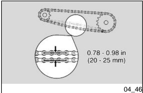
Chain clearance check (04_46)
To check the slack:
- Stop the engine.
- Place the vehicle on the stand.
- Engage neutral gear.
- Check that vertical oscillation at a middle point between pinion and crown on the lower part of the chain is of about 0.79 ÷ 0.98 in (20 ÷ 25 ~mm) .
- Move the vehicle forward so as to check vertical oscillation in other positions too. The slack should remain constant during all wheel rotation phases.
If the slack is uniform, but higher or lower than 0.79 ÷ 0.98 in (20 ÷ 25 ~mm) , adjust it as required.
IMPORTANT
IF A HIGHER CLEARANCE IS FOUND IN PLACES, THIS MEANS THAT SOME OF THE CHAIN MAILS ARE SQUASHED OR SEIZED.
TO AVOID THE RISK OF SEIZURE, LUBRICATE THE CHAIN ON A REGULAR BASIS.
If you need to tighten chain slack:
- Place the vehicle on the stand.
- Loosen the nut (1) completely.
- Loosen the two locknuts (4).
Work on the set screws (5) to adjust the clearance of the chain making sure that, on both sides of the vehicle, the same references correspond (2 - 3). - Tighten the two locknuts (4).
- Tighten the nut (1).
- Inspect the clearance of the chain.
NOTE
WHEEL CENTERING IS CARRIED OUT USING FIXED SETTINGS (2-3) WITHIN THE SEATS OF CHAIN TENSIONER PADS ON THE SWINGARMS, IN FRONT OF THE WHEEL SPINDLE.
Locking torques (N^*m)
Wheel nut (1) tightening torque
88.5 lbf ft (120 Nm).
Checking wear of chain, front and rear sprockets (04_49, 04_50, 04_51)
Check the following parts and verify that the chain, pinion and crown do not have:
Damaged rollers.
- Loosened pins.
- Dry, rusty, squashed or seized chain links.
- Excessive wear.
- Missing sealing rings.
- Excessively worn or damaged pinion or crown teeth.
IMPORTANT
IF THE CHAIN ROLLERS ARE DAMAGED, THE PINS ARE LOOSEND AND/OR THE O-RINGS ARE MISSING OR DAMAGED, THE WHOLE CHAIN APPARATUS (PINION, CROWN AND CHAIN) SHOULD BE REPLACED.
Chain lubrication and cleaning
Lubricate the chain whenever necessary. Lubricate the chain with chain spray grease. Do not wash the chain with water jets, vapor jets, high-pressure water jets and highly flammable solvents.

USE THE UTMOST CARE WHEN ADJUSTING, LUBRICATING, WASHING AND REPLACING THE CHAIN.
| Max. length | 88.19 in (2240 mm) |
| Max. width | 32.68 in (830 mm) |
| Max. height (including top fairing) | 49.21 in (1250 mm) |
| Saddle height | 37.40 in (950 mm) |
| Center to center distance | 58.46 in (1485 mm) |
| Minimum ground clearance | 12.60 in (320 mm) |
| Dry weight | 271.12 lb (123 Kg) |
| Fuel tank capacity (including reserve) | 3.17 US gal (2.64 UK gal) (12 l) |
| Fuel reserve | 0.58 US gal (0.48 UK gal) (2,2 l) |
| Engine oil capacity | 0.34 US gal (0.28 UK gal) (1.3 l) |
| Fork oil capacity | 3.94 in (100 mm) of clearance (for each stem, measured without spring and under compression) |
| Coolant capacity | 0.29 US gal (0.24 UK gal) (1.1 l) (50% water + 50% ethylene glycol antifreeze) |
| Seats | 1 |
| Chassis | Steel perimeter frame and aluminum upright |
| Front suspension | hydraulic telescopic fork, stem diam. 1.77 in (45 mm) |
DONNÉES TECHNIQUES RXV 450 - RXV 550 (VÉHICULE)
| Longueur max. | 88.19 in (2240 mm) |
| Largeur max. | 32.68 in (830 mm) |
| Hauteur max. (à la bulle) | 49.21 in (1250 mm) |
| Hauteur à la selle | 37.40 in (950 mm) |
| Distance entre axes | 58.46 in (1485 mm) |
| Garde au sol | 12.60 in (320 mm) |
| Poids à sec | 271.12 lb (123 kg) |
| Capacité du réservoir de carburant (réserve incluse) : | 3.17 US gal (2.64 UK gal) (12 l) |
| Réserve de carburant | 0.58 US gal (0.48 UK gal) (2,2 l) |
| Capacité d'huile moteur | 0.34 US gal (0.28 UK gal) (1,3 l) |
| Capacité d'huile par fourche | 3.94 mm (100 in) d'air (pour chaque tige, mesurés sans compression du ressort ni de la tige) |
| Capacité du liquide de refroidissement | 0.29 US gal (0.24 UK gal) (1,1 l) (50 % eau + 50 % antigel avec glycol éthylène) |
| Places | 1 |
| CADRE | Montant en-aluminium et treillis en tubes d'accier |
| Front suspension travel | 11.75 in (298.5 mm) |
| Rear suspension | oscillating fork and adjustable hydraulic single shock absorber |
| Rear wheel travel | 11.81 in (300 mm) (usable) |
| Front brake | disc - Diam. 10.63 in (270 mm), with hydraulic transmission |
| Rear brake | disc - Diam. 9.45 in (240 mm), with hydraulic transmission |
| Wheel rims | with spokes |
| Front wheel rim | 1.60 x 21" |
| Rear wheel rim | 2.15 x 18" |
| Front tire | 90/90 21" 54R |
| Front tire inflation pressure | 21.76 PSI (150 kPa) (1.5 bar) |
| 14.50 PSI (100 kPa) (1.0 bar) (off-road use) | |
| Rear tire | 140/80 18 70R |
| Rear tire inflation pressure | 24.66 PSI (170 kPa) (1.7 bar) |
| 15.95 PSI (110 kPa) (1.1 bar) (off-road use) |
| Model | 45RX |
| Engine | 4-stroke 2-cylinder, 4 valves per cylinder, single overhead camshaft |
| Number of cylinders | 2 |
| Total engine capacity | 27.40 cu in (449 cc) |
| Bore/stroke | 2.99 in x 1.95 in (76 mm x 49,5 mm) |
| Compression ratio | 13 ± 0.5 |
| Ignition | electric |
| Engine idling speed | 1800 ÷ 2000 rpm |
| Clutch | Oil-coated multiple disc |
| Lubricating system | Double separated lubrication with external reservoir |
| Air filter | Sponge |
| Cooling | liquid |
| Transmission | mechanical, 5 gear with pedal lever on the left hand side of the engine |
| Gear ratio | Primary: 22/56 = 1 : 2.545Final: 15/48 = 1 : 3.200 |
| \( 1^a \) | 12/31 = 1 : 2.583 (secondary)1: 21.042 (total) |
| 2nd | 13/25 = 1 : 1.923 (secondary) |
| Model | 55RX |
| Engine | 4-stroke 2-cylinder, 4 valves per cylinder, single overhead camshaft |
| Number of cylinders | 2 |
| Total engine capacity | 33.75 cu in (553 cc) |
| Bore/stroke | 3.15 in x 2.16 in (80 mm x 55,0 mm) |
| Modèle | 55RX |
| Moteur | bicylindre 4 temps, avec 4 soupapes par cylindre et un arbre à cames en tête |
| Nombre de cylindres | 2 |
| Cylindrée totale | 33.75 cu in (553 cc) |
| Compression ratio | 12.5 ± 0.5 |
| Ignition | electric |
| Engine idling speed | 1800 ÷ 2000 rpm |
| Clutch | Oil-coated multiple disc |
| Lubricating system | Double separated lubrication with external reservoir |
| Air filter | Sponge |
| Cooling | liquid |
| Transmission | mechanical, 5 gear with pedal lever on the left hand side of the engine |
| Gear ratio | Primary: 22/56 = 1 : 2.545 Final: 15/48 = 1 : 3.200 |
| 1a | 12/31 = 1 : 2.583 (secondary) 1: 21.042 (total) |
| 2nd | 13/25 = 1 : 1.923 (secondary) 1: 15.664 (total) |
| 3rd | 15/23 = 1 : 1.533 (secondary) 1: 12.489 (total) |
| 4th | 19/24 = 1 : 1.263 (secondary) 1: 10.288 (total) |
| 5th | 21/22 = 1 : 1.047 (secondary) 1: 8.533 (total) |
| Ignition | Electric |
| Standard spark plug | NGK CR8EKB |
| Spark plug electrode gap | 0.028 - 0.031 in (0.7 - 0.8 mm) |
| Resistance | 5 kΩ |
| Battery | 12V- 6Ah |
| Main fuse | 30 A |
| Secondary fuses | 5 A, 7.5 A, 15 A |
| Generator (permanent wound-magnet) | 12V - 350W |
| Low beam bulb | 12V - 55W |
| High beam bulb | 12V - 60W |
| Front side light bulb | 12V - 3W |
| Turn indicators bulb | with microlamps |
COMPOSANTS ÉLECTRIQUES
| Allumage | Électronique. |
| Bougie standard | NGK CR8EKB |
| Distance entre les électrodes des bougies | 0.028 - 0.031 in (0.7 - 0.8 mm) |
| Résistance | 5 kΩ |
| Batterie | 12 V - 6 Ah |
| Fusible principal | 30 A |
| Fusibles secondaires | 5 A, 7,5 A, 15 A |
| Générateur (à aimant permanent) | 12 V - 350 W |
| Ampoule du feu de croisement | 12 V - 55 W |
| Ampoule du feu de route | 12 V - 60 W |
| Ampoule du feu de position avant | 12 V - 3 W |
| Ampoule des clignotants | À microampoules |
| License plate light bulb | 12V - 5W |
| Tail light/brake light lamp | LED |
| Dashboard light bulb | LED |
| N gear warning light | LED |
| Engine oil pressure warning light | LED |
| Engine control system warning light | LED |
| Low fuel warning light | LED |
| High-beam light warning light | LED |
| Turn signal warning light | LED |
| Overrevving warning light | LED |
The vehicle is provided with a tool kit which includes:
- Container.
- Reversible flathead/Phillips head screwdriver 0.24 × 5.04 in (6 x 128 mm).
- Handle for the reversible screwdriver.
- 0.63 × 1.97 in (16 × 50 ~mm) box spanner with 0.51 × 0.79 in (13 × 20 ~mm) welded hex.
Trousse a outfits
RXV versions are supplied with a number of accessories not installed:
Cooling electric fan
- Stand safety rubber band.
Avertissements
Scheduled servicing table
IMPORTANT

THE MAINTENANCE OPERATIONS LISTED MUST BE CARRIED OUT BY A Dealer OR AN Authorized aprilia Workshop, OTHERWISE THE WARRANTY WILL BE VOIDED.
NOTE
PERFORM THE MAINTENANCE PROCEDURES AT HALF THE INTERVALS INDICATED IF THE VEHICLE IS USED IN RAINY OR DUSTY AREAS, ON POOR ROADS OR IN CASE OF SPORT DRIVING.
| Mi x 1.000 | 0.3 | 1.9 | 3.7 | 5.6 | 7.5 | 9.3 | 11.2 | 13.0 | 14.9 | 16.7 | 18.6 |
| Km x 1,000 | 0.5 | 3 | 6 | 9 | 12 | 15 | 18 | 21 | 24 | 27 | 30 |
| Throttle body assembly bolt torque | I | I | I | I | I | I | I | I | I | I | I |
| Throttle bodies | A | A | A | A | A | A | A | A | A | A | A |
| Air filter and air box | I | I | I | I | I | I | I | I | I | I | I |
| Gasoline tubing | I | I | I | I | I | I | I | I | I | I | I |
| Idling adjustment | A | A | A | A | A | A | A | A | A | A | A |
| Transmission oil | R | R | R | R | R | R | R | R | R | R | R |
| Clutch spring | - | I | I | I | I | I | I | I | I | I | I |
| Clutch discs | - | I | I | I | I | I | I | I | I | I | I |
| Clutch lever | I | I | I | I | I | I | I | I | I | I | I |
| Radiator coolant level and expansion tank | I | I | I | I | I | I | I | I | I | I | I |
| System seals | - | I | I | I | I | I | I | I | I | I | I |
| Engine oil and engine oil filter | R | R | R | R | R | R | R | R | R | R | R |
| Oil tubing | I | I | I | I | I | I | I | I | I | I | I |
| Gas cable | A | A | A | A | A | A | A | A | A | A | A |
| Brake fluid level | I | I | I | I | I | I | I | I | I | I | I |
| Brake tubing | I | I | I | I | I | I | I | I | I | I | I |
| Brake system bolt torque | I | I | I | I | I | I | I | I | I | I | I |
| Disc brake thickness | - | I | I | I | I | I | I | I | I | I | I |
| Brake pads thickness | - | I | I | I | I | I | I | I | I | I | I |
| Electrical contacts and switches | - | I | I | I | I | I | I | I | I | I | I |
| Battery connecting | - | I | I | I | I | I | I | I | I | I | I |
| Lights - Operation /orientation | A | A | A | A | A | A | A | A | A | A | A |
| Electrical system performance | I | I | I | I | I | I | I | I | I | I | I |
| Exhaust | - | I | I | I | I | I | I | I | I | I | I |
| Tire condition and pressure | I | I | I | I | I | I | I | I | I | I | I |
| Wheel bearings | I | I | I | I | I | I | I | I | I | I | I |
| Spokes and rim coaxiality | I | I | I | I | I | I | I | I | I | I | I |
| Wheel spindle nut and bolt | I | I | I | I | I | I | I | I | I | I | I |
| Engine mounting bolt torque | I | I | I | I | I | I | I | I | I | I | I |
| Body nut and bolt torque | I | I | I | I | I | I | I | I | I | I | I |
| Fork dust seal | - | C | C | C | C | C | C | C | C | C | C |
| Fork struts ** | - | I | I | I | I | I | I | I | I | I | I |
| Fork | I | I | I | I | I | I | I | I | I | I | I |
| Front fork plates and feet bolt torque | I | I | I | I | I | I | I | I | I | I | I |
| Shock absorber pins tightening torque | I | I | I | I | I | I | I | I | I | I | I |
| Shock absorber | I | I | I | I | I | I | I | I | I | I | I |
| Steering bearing slack | I | I | I | I | I | I | I | I | I | I | I |
| Headstock dust seal | C | C | C | C | C | C | C | C | C | C | C |
| Transmission chain | I | I | I | I | I | I | I | I | I | I | I |
| Chain links, crown, and chain guide | I | I | I | I | I | I | I | I | I | I | I |
| Steering bearings | L | L | L | L | L | L | L | L | L | L | L |
| Clutch lever pin | - | L | L | L | L | L | L | L | L | L | L |
| Gas cable | - | L | L | L | L | L | L | L | L | L | L |
| Driver's footrest pins | - | L | L | L | L | L | L | L | L | L | L |
| Rear suspension levers | - | L | L | L | L | L | L | L | L | L | L |
| Side stand pin | - | L | L | L | L | L | L | L | L | L | L |
| Front wheel bearings and spindle | - | L | L | L | L | L | L | L | L | L | L |
| Rear swing arm pin | - | L | L | L | L | L | L | L | L | L | L |
| Rear wheel bearings and spindle | - | L | L | L | L | L | L | L | L | L | L |
| Sponge air filter | - | - | R | - | R | - | R | - | R | - | R |
| Spark plugs | - | - | R | - | R | - | R | - | R | - | R |
| Complete transmission | - | - | - | I | - | - | I | - | - | I | - |
| High pressure and non-return spring valve | - | - | - | I | - | - | I | - | - | I | - |
| Cylinder liners | - | - | - | I | - | - | I | - | - | I | - |
| Conrod brass bearings and crankshaft main bearings | - | - | - | I | - | - | I | - | - | I | - |
| Start up gears | - | - | - | I | - | - | I | - | - | I | - |
| Oil pump gears | - | - | - | I | - | - | I | - | - | I | - |
| Cylinder head lubrication jets | - | - | - | C | - | - | C | - | - | C | - |
| Pistons and belts | - | - | - | R | - | - | R | - | - | R | - |
| Piston pins | - | - | - | I | - | - | I | - | - | I | - |
| Equalizers rollers | - | - | - | I | - | - | I | - | - | I | - |
| Valve lifter | - | - | - | I | - | - | I | - | - | I | - |
| Camshaft wear | - | - | - | I | - | - | I | - | - | I | - |
| Camshaft bearings | - | - | - | I | - | - | I | - | - | I | - |
| Valve seat seal | - | - | - | I | - | - | I | - | - | I | - |
| Valves | - | - | - | I | - | - | I | - | - | I | - |
| Valve clearance | - | - | - | A | - | - | A | - | - | A | - |
| Valve guides | - | - | - | I | - | - | I | - | - | I | - |
| Spring holder washers, plates, tappets | - | - | - | I | - | - | I | - | - | I | - |
| Chain tightener teeth | - | - | - | I | - | - | I | - | - | I | - |
| Valve springs | - | - | - | I | - | - | I | - | - | I | - |
| Gearing chain | - | - | - | I | - | - | I | - | - | I | - |
| Transmission chain pads | - | - | - | I | - | - | I | - | - | I | - |
| Fuel pump | - | - | - | I | - | - | I | - | - | I | - |
| Fork (complete maintenance) | - | - | - | I | - | - | I | - | - | I | - |
| Fork oil | - | - | - | R | - | - | R | - | - | R | - |
| Shock absorber (complete maintenance) | - | - | - | I | - | - | I | - | - | I | - |
| Piston bearing clearance | - | - | - | I | - | - | I | - | - | I | - |
| Chain guide plate | - | - | - | I | - | - | I | - | - | I | - |
| Chain guide slide | - | - | - | I | - | - | I | - | - | I | - |
| Chain tightener roller | - | - | - | I | - | - | I | - | - | I | - |
| Chain guide plate | - | - | - | I | - | - | I | - | - | I | - |
| Brake fluid *** | - | - | - | - | - | - | - | - | - | - | - |
I: CONTROLLARE E PULIRE, REGOLARE, LUBRIFICARE O SOSTITUIRE SE NECESSARIO
C: PULIRE, R: SOSTITUIRE, A: REGOLARE, L: LUBRIFICARE
Fine rodaggio
Effettuare spurgo
** Sostituire aglianno
SCHEDA DI MANUTENZIONE PERIODICA PER VEICOLI IN VERSIONE ORIGINALE (DEPOTENZIATI) PER USO STRADALE
| Hours of use | 3 | 15 | 30 | 45 | 60 | 75 | 90 | 105 | 120 | 135 | 150 |
| Throttle body assembly bolt torque | I | I | I | I | I | I | I | I | I | I | I |
| Throttle bodies | A | A | A | A | A | A | A | A | A | A | A |
| Air filter and air box | I | I | I | I | I | I | I | I | I | I | I |
| Gasoline tubing | I | I | I | I | I | I | I | I | I | I | I |
| Idling adjustment | A | A | A | A | A | A | A | A | A | A | A |
| Transmission oil | R | R | R | R | R | R | R | R | R | R | R |
| Clutch spring | - | I | I | I | I | I | I | I | I | I | I |
| Clutch discs | - | I | I | I | I | I | I | I | I | I | I |
| Clutch lever | I | I | I | I | I | I | I | I | I | I | I |
| Radiator coolant level and expansion tank | I | I | I | I | I | I | I | I | I | I | I |
| System seals | - | I | I | I | I | I | I | I | I | I | I |
| Engine oil and engine oil filter | R | R | R | R | R | R | R | R | R | R | R |
| Oil tubing | I | I | I | I | I | I | I | I | I | I | I |
| Gas cable | A | A | A | A | A | A | A | A | A | A | A |
| Brake fluid level | I | I | I | I | I | I | I | I | I | I | I |
| Brake tubing | I | I | I | I | I | I | I | I | I | I | I |
| Brake system bolt torque | I | I | I | I | I | I | I | I | I | I | I |
| Disc brake thickness | - | I | I | I | I | I | I | I | I | I | I |
| Brake pads thickness | - | I | I | I | I | I | I | I | I | I | I |
| Electrical contacts and switches | - | I | I | I | I | I | I | I | I | I | I |
| Battery connecting | - | I | I | I | I | I | I | I | I | I | I |
| Lights - Operation /orientation | A | A | A | A | A | A | A | A | A | A | A |
| Electrical system performance | I | I | I | I | I | I | I | I | I | I | I |
| Exhaust | - | I | I | I | I | I | I | I | I | I | I |
| Tire condition and pressure | I | I | I | I | I | I | I | I | I | I | I |
| Wheel bearings | I | I | I | I | I | I | I | I | I | I | I |
| Spokes and rim coaxiality | I | I | I | I | I | I | I | I | I | I | I |
| Wheel spindle nut and bolt | I | I | I | I | I | I | I | I | I | I | I |
| Engine mounting bolt torque | I | I | I | I | I | I | I | I | I | I | I |
| Body nut and bolt torque | I | I | I | I | I | I | I | I | I | I | I |
| Fork dust seal | - | C | C | C | C | C | C | C | C | C | C |
| Fork struts ** | - | I | I | I | I | I | I | I | I | I | I |
| Fork | I | I | I | I | I | I | I | I | I | I | I |
| Front fork plates and feet bolt torque | I | I | I | I | I | I | I | I | I | I | I |
| Shock absorber pins tightening torque | I | I | I | I | I | I | I | I | I | I | I |
| Shock absorber | I | I | I | I | I | I | I | I | I | I | I |
| Steering bearing slack | I | I | I | I | I | I | I | I | I | I | I |
| Headstock dust seal | C | C | C | C | C | C | C | C | C | C | C |
| Transmission chain | I | I | I | I | I | I | I | I | I | I | I |
| Chain links, crown, and chain guide | I | I | I | I | I | I | I | I | I | I | I |
| Steering bearings | L | L | L | L | L | L | L | L | L | L | L |
| Clutch lever pin | - | L | L | L | L | L | L | L | L | L | L |
| Gas cable | - | L | L | L | L | L | L | L | L | L | L |
| Driver's footrest pins | - | L | L | L | L | L | L | L | L | L | L |
| Rear suspension levers | - | L | L | L | L | L | L | L | L | L | L |
| Side stand pin | - | L | L | L | L | L | L | L | L | L | L |
| Front wheel bearings and spindle | - | L | L | L | L | L | L | L | L | L | L |
| Rear swing arm pin | - | L | L | L | L | L | L | L | L | L | L |
| Rear wheel bearings and spindle | - | L | L | L | L | L | L | L | L | L | L |
| Sponge air filter | - | - | - | - | R | - | - | - | R | - | - |
| Spark plugs | - | - | - | - | R | - | - | - | R | - | - |
| Complete transmission | - | - | - | - | - | - | I | - | - | - | - |
| High pressure and non-return spring valve | - | - | - | - | - | - | I | - | - | - | - |
| Cylinder liners | - | - | - | - | - | - | I | - | - | - | - |
| Conrod brass bearings and crankshaft main bearings | - | - | - | - | - | - | I | - | - | - | - |
| Start up gears | - | - | - | - | - | - | I | - | - | - | - |
| Oil pump gears | - | - | - | - | - | - | I | - | - | - | - |
| Cylinder head lubrication jets | - | - | - | - | - | - | C | - | - | - | - |
| Pistons and belts | - | - | - | - | - | - | R | - | - | - | - |
| Piston pins | - | - | - | - | - | - | I | - | - | - | - |
| Equalizers rollers | - | - | - | - | - | - | I | - | - | - | - |
| Valve lifter | - | - | - | - | - | - | I | - | - | - | - |
| Camshaft wear | - | - | - | - | - | - | I | - | - | - | - |
| Camshaft bearings | - | - | - | - | - | - | I | - | - | - | - |
| Valve seat seal | - | - | - | - | - | - | I | - | - | - | - |
| Valves | - | - | - | - | - | - | I | - | - | - | - |
| Valve clearance | - | - | - | - | - | - | A | - | - | - | - |
| Valve guides | - | - | - | - | - | - | I | - | - | - | - |
| Spring holder washers, plates, tappets | - | - | - | - | - | - | I | - | - | - | - |
| Chain tightener teeth | - | - | - | - | - | - | I | - | - | - | - |
| Valve springs | - | - | - | - | - | - | I | - | - | - | - |
| Gearing chain | - | - | - | - | - | - | I | - | - | - | - |
| Transmission chain pads | - | - | - | - | - | - | I | - | - | - | - |
| Fuel pump | - | - | - | - | - | - | I | - | - | - | - |
| Fork (complete maintenance) | - | - | - | - | - | - | I | - | - | - | - |
| Fork oil | - | - | - | - | - | - | R | - | - | - | - |
| Shock absorber (complete maintenance) | - | - | - | - | - | - | I | - | - | - | - |
| Piston bearing clearance | - | - | - | - | - | - | I | - | - | - | - |
| Chain guide plate | - | - | - | - | - | - | I | - | - | - | - |
| Chain guide slide | - | - | - | - | - | - | I | - | - | - | - |
| Chain tightener roller | - | - | - | - | - | - | I | - | - | - | - |
| Chain guide plate | - | - | - | - | - | - | I | - | - | - | - |
| Brake fluid *** | - | - | - | - | - | - | - | - | - | - | - |
I: CHECK AND CLEAN, ADJUST, LUBRICATE, OR REPLACE IF NECESSARY
C: CHECK, R: REPLACE, A: ADJUST, L: LUBRICATE
- End of run-in period
** Drain
*** Replace every year
FICHE D'ENTRETIEN PÉRIODIQUE POUR VÉHICULES EN VERSION LIBRE POUR UNE UTILISATION SPORTIVE DE PLAISANCE.
| Hours of use | 3 | 15 | 30 | 45 | 60 | 75 | 90 | 105 | 120 | 135 | 150 |
| Throttle body assembly bolt torque | I | I | I | I | I | I | I | I | I | I | I |
| Throttle bodies | A | A | A | A | A | A | A | A | A | A | A |
| Air filter and air box | I | I | I | I | I | I | I | I | I | I | I |
| Gasoline tubing | I | I | I | I | I | I | I | I | I | I | I |
| Idling adjustment | A | A | A | A | A | A | A | A | A | A | A |
| Transmission oil | R | R | R | R | R | R | R | R | R | R | R |
| Clutch spring | - | I | I | I | I | I | I | I | I | I | I |
| Clutch discs | - | I | I | I | I | I | I | I | I | I | I |
| Clutch lever | I | I | I | I | I | I | I | I | I | I | I |
| Radiator coolant level and expansion tank | I | I | I | I | I | I | I | I | I | I | I |
| System seals | - | I | I | I | I | I | I | I | I | I | I |
| Engine oil and engine oil filter | R | R | R | R | R | R | R | R | R | R | R |
| Oil tubing | I | I | I | I | I | I | I | I | I | I | I |
| Gas cable | A | A | A | A | A | A | A | A | A | A | A |
| Brake fluid level | I | I | I | I | I | I | I | I | I | I | I |
| Brake tubing | I | I | I | I | I | I | I | I | I | I | I |
| Brake system bolt torque | I | I | I | I | I | I | I | I | I | I | I |
| Disc brake thickness | - | I | I | I | I | I | I | I | I | I | I |
| Brake pads thickness | - | I | I | I | I | I | I | I | I | I | I |
| Electrical contacts and switches | - | I | I | I | I | I | I | I | I | I | I |
| Battery connecting | - | I | I | I | I | I | I | I | I | I | I |
| Lights - Operation /orientation | A | A | A | A | A | A | A | A | A | A | A |
| Electrical system performance | I | I | I | I | I | I | I | I | I | I | I |
| Exhaust | - | I | I | I | I | I | I | I | I | I | I |
| Tire condition and pressure | I | I | I | I | I | I | I | I | I | I | I |
| Wheel bearings | I | I | I | I | I | I | I | I | I | I | I |
| Spokes and rim coaxiality | I | I | I | I | I | I | I | I | I | I | I |
| Wheel spindle nut and bolt | I | I | I | I | I | I | I | I | I | I | I |
| Engine mounting bolt torque | I | I | I | I | I | I | I | I | I | I | I |
| Body nut and bolt torque | I | I | I | I | I | I | I | I | I | I | I |
| Fork dust seal | - | C | C | C | C | C | C | C | C | C | C |
| Fork struts ** | - | I | I | I | I | I | I | I | I | I | I |
| Fork | I | I | I | I | I | I | I | I | I | I | I |
| Front fork plates and feet bolt torque | I | I | I | I | I | I | I | I | I | I | I |
| Shock absorber pins tightening torque | I | I | I | I | I | I | I | I | I | I | I |
| Shock absorber | I | I | I | I | I | I | I | I | I | I | I |
| Steering bearing slack | I | I | I | I | I | I | I | I | I | I | I |
| Headstock dust seal | C | C | C | C | C | C | C | C | C | C | C |
| Transmission chain | I | I | I | I | I | I | I | I | I | I | I |
| Chain links, crown, and chain guide | I | I | I | I | I | I | I | I | I | I | I |
| Steering bearings | L | L | L | L | L | L | L | L | L | L | L |
| Clutch lever pin | - | L | L | L | L | L | L | L | L | L | L |
| Gas cable | - | L | L | L | L | L | L | L | L | L | L |
| Driver's footrest pins | - | L | L | L | L | L | L | L | L | L | L |
| Rear suspension levers | - | L | L | L | L | L | L | L | L | L | L |
| Side stand pin | - | L | L | L | L | L | L | L | L | L | L |
| Front wheel bearings and spindle | - | L | L | L | L | L | L | L | L | L | L |
| Rear swing arm pin | - | L | L | L | L | L | L | L | L | L | L |
| Rear wheel bearings and spindle | - | L | L | L | L | L | L | L | L | L | L |
| Sponge air filter | - | - | - | R | - | - | - | R | - | - | - |
| Spark plugs | - | - | - | R | - | - | - | R | - | - | - |
| Complete transmission | - | - | - | - | - | I | - | - | - | - | - |
| High pressure and non-return spring valve | - | - | - | - | - | I | - | - | - | - | - |
| Cylinder liners | - | - | - | - | - | I | - | - | - | - | - |
| Conrod brass bearings and crankshaft main bearings | - | - | - | - | - | I | - | - | - | - | - |
| Start up gears | - | - | - | - | - | I | - | - | - | - | - |
| Oil pump gears | - | - | - | - | - | I | - | - | - | - | - |
| Cylinder head lubrication jets | - | - | - | - | - | C | - | - | - | - | - |
| Pistons and belts | - | - | - | - | - | R | - | - | - | - | - |
| Piston pins | - | - | - | - | - | I | - | - | - | - | - |
| Equalizers rollers | - | - | - | - | - | I | - | - | - | - | - |
| Valve lifter | - | - | - | - | - | I | - | - | - | - | - |
| Camshaft wear | - | - | - | - | - | I | - | - | - | - | - |
| Camshaft bearings | - | - | - | - | - | I | - | - | - | - | - |
| Valve seat seal | - | - | - | - | - | I | - | - | - | - | - |
| Valves | - | - | - | - | - | I | - | - | - | - | - |
| Valve clearance | - | - | - | - | - | A | - | - | - | - | - |
| Valve guides | - | - | - | - | - | I | - | - | - | - | - |
| Spring holder washers, plates, tappets | - | - | - | - | - | I | - | - | - | - | - |
| Chain tightener teeth | - | - | - | - | - | I | - | - | - | - | - |
| Valve springs | - | - | - | - | - | I | - | - | - | - | - |
| Gearing chain | - | - | - | - | - | I | - | - | - | - | - |
| Transmission chain pads | - | - | - | - | - | I | - | - | - | - | - |
| Fuel pump | - | - | - | - | - | I | - | - | - | - | - |
| Fork (complete maintenance) | - | - | - | - | - | I | - | - | - | - | - |
| Fork oil | - | - | - | - | - | R | - | - | - | - | - |
| Shock absorber (complete maintenance) | - | - | - | - | - | I | - | - | - | - | - |
| Piston bearing clearance | - | - | - | - | - | I | - | - | - | - | - |
| Chain guide plate | - | - | - | - | - | I | - | - | - | - | - |
| Chain guide slide | - | - | - | - | - | I | - | - | - | - | - |
| Chain tightener roller | - | - | - | - | - | I | - | - | - | - | - |
| Chain guide plate | - | - | - | - | - | I | - | - | - | - | - |
| Brake fluid *** | - | - | - | - | - | - | - | - | - | - | - |
I: CHECK AND CLEAN, ADJUST, LUBRICATE, OR REPLACE IF NECESSARY
C: CHECK, R: REPLACE, A: ADJUST, L: LUBRICATE
End of run-in period
* Drain
*** Replace every year
FICHE D'ENTRETIEN PÉRIODIQUE POUR VÉHICULES EN VERSION LIBRE POUR UNE UTILISATION SPORTIVE DE COMPÉTITION.
| Product | Description | Specifications |
| AGIP RACING 4T 10W-60 | Engine oil | Use brand-name oil with performance characteristics at or above the level CCMC G-4 A.P.I. SG. SAE 10W-60 |
| AGIP RACING 4T 10W-60 | Transmission oil | - |
| AGIP PERMANENT SPEZIAL | Coolant | Biodegradable coolant, ready-to-use, with long-life technology and characteristics (red). Ensures protection from freezing down to -40°. Meets CUNA 956-16 norms. |
| AGIP BRAKE 4 | Brake fluid | As an alternative to the recommended fluid, other fluids with performance equal to or higher than the specifications may be used. Synthetic fluid SAE J1703, NHTSA 116 DOT 4, ISO 4925 |
| AGIP MP GREASE | Bearings and other lubrication points | As an alternative to the suggested product, use brand-name grease for spigot bearings, for use at temperatures between -22°F - +284°F (-30°C - +140°C), melting point 302°F - 446°F (+150°C - +230°C), with a high level of corrosion protection, and high resistance to water and rust. |
| AGIP FORK 7.5W | Fork oil | SAE 7.5W |
PRODUITS CONSEILLÉS
Engine oil: 20, 114, 117
Engine stop: 67
F
Fork: 84
Fuel: 14
Fuses: 147
H
Headlight: 154
Horn: 65
1
Identification: 70
Instrument panel: 54
M
Maintenance: 113, 185
s
Saddle: 70
Shock absorbers: 80
Spark plug: 124
Stand: 23, 96
Start-up: 67
T
Technical data: 173
Tires: 123
Transmission: 165
W
Warning lights: 17
TABLE DES MATIERÉS
A
Accessoires: 183
Amortisseurs: 80
Ampoules: 152
B
Batterie: 22, 146
Bougie: 124
C
Carburant: 14
Chaine: 165, 167-169, 171
Clignotants: 66
Only the mechanics of the official aprilia Service Network know this vehicle well, thanks to constant technical professional development and aprilia-specific training programs, and have the tools needed to carry out maintenance and repair operations correctly.
The bike's reliability also depends on its mechanical condition. Checking the vehicle before setting off, carrying out routine maintenance and using only aprilia Original Spare parts are essential factors!
To find your nearest Official Dealership and or Service Center, use the Yellow Pages or the map provided on our Official Internet Site:
www.aprilia.com
Only by asking for aprilia Original Spare Parts will you get a product designed and tested during the bike's development phase. aprilia Original Spare Parts are subject to systematic quality control procedures so that their reliability and performance over time is guaranteed.
The descriptions and illustrations supplied in this publication are not meant to be binding. While the basic features as described and illustrated in this manual remain unchanged, aprilia reserves the right, at any time and without being required to update this publication beforehand, to make any changes to components, parts or accessory supplies, which it deems necessary to improve the product or which are required for manufacturing or commercial reasons.
Not all versions shown in this publication are available in all countries. The availability of individual versions should be checked with the official aprilia Sales Network.
Copyright 2008- aprilia. All rights reserved. Reproduction in whole or in part of this publication is prohibited. aprilia - After sales service.
The aprilia brand is owned by Piaggio & C. S.p.A.
LA VALEUR DE L'ASSISTANCE
- Congratulations on your new RXV.
- IMPORTANT NOTICE ON VEHICLE USE AND LEGAL WARRANTY
- APRILIA WOULD LIKE TO THANK YOU
- Safeguarding the environment
- VEHICLE 49
- RÉGLES GÉNÉRALES 11
- General safety rules
- Premisses
- N.B.
- Monoxyde carbone
- ATTENTION
- Carburant
- IMPORTANT
- Hot components
- Start off and Riding
- Composants chauds
- Départ
- Warning lights
- voyants
- Brake and clutch fluid
- Stand
- Bequille
- Precautions general advice
- Reporting of defects that affect safety
- Road regulations and use of the motorcycle
- Noise emission warranty
- Piaggio Group Americas, Inc.
- Origin of the emissions
- Violation/Falsification
- Problems that may affect the motorcycle emissions
- Symptoms:
- Position of the warning labels (01_02)
- Legende:
- Étiquette 3 (01_06)
- Étiquette 4 (01_07)
- Étiquette 5 (01_08)
- Label 7 (01_10)
- Étiquette 6 (01_09)
- Your warranty rights and obligations
- YOUR RIGHTS AND RESPONSIBILITIES UNDER THE WARRANTY
- GARANTIE DU PROPRIÉTAIRE
- RESPONSABILITÉ
- aprilia - DÉCLARATION DE GARANTIE LIMITÉE SUR LE SYSTème DE CONTROLLE DES ÉMISSIONS
- I - Couverture
- II - Limites
- III - Limited liability
- V - This warranty is in addition to the manufacturer llimited vehicle warranty
- VI - Additional information
- Piaggio & C. S.p.A.
- Arrangement of the main components (02_02)
- KEY
- Emplacement composants principaux (02_02)
- LEGENDE
- Instruments de bord analogiques (02_04)
- Groupe tímoins
- Horloge
- Tension de batterie
- COMMANDES
- ODO
- TRIP
- HEURE
- RéGLAGE
- COMPTE-TOURS
- RéGLAGE DU SURRÉGIME
- ICONE DE LA BATTERIE
- NOTE
- Locking the handlebar (02_18)
- Activation verrou de direction (02_18)
- Turn signal selector. (02_20)
- High/low beam selector (02_21)
- Start-up button (02_22)
- Opening the saddle (02_24, 02_25)
- Ouverture de la selle (02_24, 02_25)
- L'identification (02_26, 02_27)
- NUMERO DE MOTEUR
- NUMERO DE CADRE
- \section*{Caracteristiques techniques}
- Rear shock absorbers adjustment (03_02, 03_03, 03_04, 03_05)
- REAR SHOCK ABSORBER ADJUSTMENT
- Front fork adjustment (03_06, 03_07)
- FRONT FORK ADJUSTMENT
- Standard front suspension adjustment:
- Running-In
- Rodage
- Follow the guidelines detailed below:
- Arrive a ce point :
- Démarrage à froid:
- Stopping the engine (03_13)
- To park the vehicle:
- Bequille (03_14)
- VÉTEMENTS
- ACCESSIONS
- CHARGE
- REPLACEMENT
- Les pneus
- Minimum tread depth:
- Spark plug removal (04_11, 04_12, 04_13)
- Depose de la bougie (04_11, 04_12, 04_13)
- Characteristic
- Couples de blocage (N*m)
- SPARK ARRESTER
- Refilling
- Batterie (04_26, 04_27, 04_28)
- To check:
- ARRANGEMENT OF MAIN FUSES
- DISPOSITION DES FUSIBLES PRINCIPAUX
- Front light group (04_34, 04_35, 04_36, 04_37, 04_38)
- To replace:
- Side light lamp «1»
- High/low beam light bulb «2»
- Proceed as follows:
- APRÉS LE REMISAGE
- Cleaning the vehicle
- Transport
- Chaine de transmission
- Chain clearance check (04_46)
- Locking torques (N*m)
- Checking wear of chain, front and rear sprockets (04_49, 04_50, 04_51)
- Chain lubrication and cleaning
- Trousse a outfits
- Avertissements
- Scheduled servicing table
- F
- H
- 1
- M
- s
- T
- W
- TABLE DES MATIERÉS
- A
- B
- C
- LA VALEUR DE L'ASSISTANCE
Brand : APRILIA
Model : RXV 550
Category : Off-road motorcycle