BFS440 - MAKITA - Free user manual and instructions
Find the device manual for free BFS440 MAKITA in PDF.
Download the instructions for your in PDF format for free! Find your manual BFS440 - MAKITA and take your electronic device back in hand. On this page are published all the documents necessary for the use of your device. BFS440 by MAKITA.
USER MANUAL BFS440 MAKITA
UILOCLLC GB Cordless Screwdriver
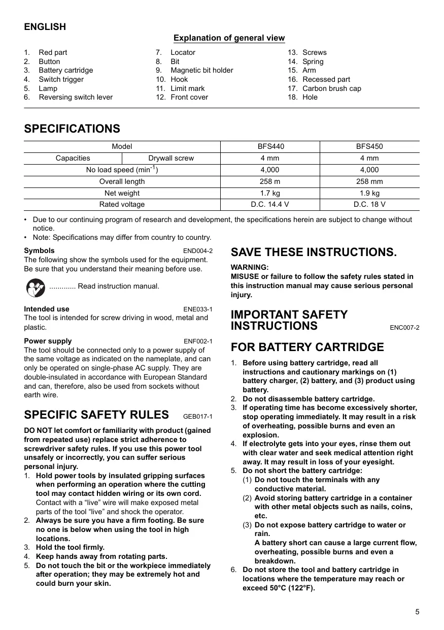
ENGLISH Explanation of general view
1. Red part 7. Locator 13. Screws 2. Button 8. Bit 14. Spring 3. Battery cartridge 9. Magnetic bit holder 15. Arm 4. Switch trigger 10. Hook 16. Recessed part 5. Lamp 11. Limit mark 17. Carbon brush cap 6. Reversing switch lever 12. Front cover 18. Hole SPECIFICATIONS Model BFS440 BFS450 Capacities I Drywall screw 4 mm 4 mm No load speed (min?) 4,000 4,000 Overall length 258 m 258 mm Net weight 17kg 12 kg Rated voltage D.C. 144V DC.18V
+ Due to our continuing program of research and development, the speci
notice. + Note: Specifications may differ from country to country.
Symbols ENDO04-2 The following show the symbols used for the equipment. Be sure that you understand their meaning before use.
Read instruction manual.
Intended use ENE033-1 The tool is intended for screw driving in wood, metal and plastic.
Power supply ENFO02-1 The tool should be connected only to a power supply of the same voltage as indicated on the nameplate, and can only be operated on single-phase AC supply. They are double-insulated in accordance with European Standard and can, therefore, also be used from sockets without earth wire.
SPECIFIC SAFETY RULES DO NOT let comfort or familiarity with product (gained from repeated use) replace strict adherence to screwdriver safety rules. If you use this power tool unsafely or incorrectly, you can suffer serious personal injury.
1. Hold power tools by insulated gripping surfaces when performing an operation where the cutting tool may contact hidden wiring or its own cord. Contact with a “live” wire will make exposed metal parts of the tool “live” and shock the operator.
2. Always be sure you have a firm footing. Be sure no one is below when using the tool in high locations.
3. Hold the tool firmly.
4. Keep hands away from rotating parts.
5. Do not touch the bit or the workpiece immediately after operation; they may be extremely hot and could burn your skin.
ations herein are subject to change without
SAVE THESE INSTRUCTIONS.
MISUSE or failure to follow the safety rules stated in this instruction manual may cause serious personal injury.
IMPORTANT SAFETY INSTRUCTIONS FOR BATTERY CARTRIDGE
1. Before using battery cartridge, read all instructions and cautionary markings on (1) battery charger, (2) battery, and (3) product using battery.
Do not disassemble battery cartridge.
H operating time has become excessively shorter,
Stop operating immediately. It may result in a risk
of overheating, possible burns and even an
4. M electrolyte gets into your eyes, rinse them out with clear water and seek medical attention right away. It may result in loss of your eyesight.
5. Do not short the battery cartridge:
{1) Do not touch the terminals with any conductive material.
(2) Avoid storing battery cartridge in a container with other metal objects such as nails, coins, etc.
(8) Do not expose battery cartridge to water or rain.
A battery short can cause a large current flow, overheating, possible burns and even a breakdown.
6. Do not store the tool and battery cartridge in locations where the temperature may reach or exceed 50°C (122°F).
7. Do not incinerate the battery cartridge even if it is severely damaged or is completely worn out. The battery cartridge can explode in a fire.
8. Be careful not to drop or strike battery.
SAVE THESE INSTRUCTIONS.
Tips for maintaining maximum battery life
1. Charge the battery cartridge before completely discharged. Always stop tool operation and charge the battery cartridge when you notice less tool power.
2. Never recharge a fully charged battery cartridge. Overcharging shortens the battery service life.
3. Charge the battery cartridge with room temperature at 10°C - 40°C (50°F - 104°F). Let a hot battery cartridge cool down before charging it.
FUNCTIONAL DESCRIPTION CAUTION:
+ Always be sure that the tool is switched off and the battery cartridge is removed before adjusting or checking function on the tool.
Installing or removing battery cartridge (Fig. 1)
Always switch off the tool before insertion or removal of the battery cartridge
To remove the battery cartridge, withdrawr it from the tool while sliding the button on the front of the cartridge To insert the battery cartridge, align the tongue on the battery cartridge with the groove in the housing and slip it into place. Always insert it all the way until it locks in place with a litle click. If you can see the red part on the upper side of the button, itis not locked completely. Insert it fully until the red part cannot be seen. If not, it may accidentally fall out of the tool, causing injury to you or someone around you.
Do not use force when inserting the battery cartridge. If the cartridge does not slide in easily it is not being inserted correctiy.
Switch action (Fig. 2)
+ Before inserting the battery cartridge into the tool, always check to see that the switch trigger actuates properly and returns to the “OFF” position when released.
To start the tool, simply pull the switch trigger. Release
the switch trigger to Stop.
Lighting up the front lamp (Fig. 3)
+ Do not look in the light or see the source of light directly.
Pull the switch trigger to light up the lamp. The lamp
keeps on lighting while the switch trigger is being pulled.
The lamp goes out 10 -15 seconds after releasing the
+ Use a dry cloth to wipe the dirt of the lens of lamp. Be careful not to scratch the lens of lamp, or it may lower the illumination
Reversing switch action (Fig. 4)
This tool has a reversing switch to change the direction of rotation. Depress the reversing switch lever from the
A side for clockwise rotation or from the B side for counterclockwise rotation.
When the reversing switch lever is in the neutral position, the switch trigger cannot be pulled.
+_ Always check the direction of rotation before operation.
+ Use the reversing switch only after the tool comes to a complete stop. Changing the direction of rotation before the tool stops may damage the tool.
When not operating the tool, always set the reversing
switch lever to the neutral position
Depth adjustment (Fig. 5)
The depth can be adjusted by turning the locator. Turn it in*B” direction for less depth and in ‘A’ direction for more depth. One full tum of the locator equals 1.5 mm change in depth
Adjust the locator so that the distance between the tip of the locator and the screw head is approximately 1 mm as shown in the figures. Drive a trial screwr into your material or a piece of duplicate material. the depth is still not suitable for the screw, continue adjusting until you obtain the proper depth setting. (Fig. 6 & 7)
+ Always be sure that the tool is switched off and the battery cartridge is removed before carrying out any work on the tool.
Installing or removing the bi To remove the bit, pull the locator. Then grasp the bit with a pair of pliers and pull the bit out of the magnetic bit holder. Sometimes, it helps to wiggle the bit with the pliers as you pull (Fig. 8)
To install the bit, push it firmly into the magnetic bit holder. Then install the locator by pushing it firmiy back. (Fig. 9)
Bit storage (Fig. 10)
Fit the bit into the protrusion at the tool.
The carry hook is convenient for temporarily hooking the tool. It can be installed on either side of the tool.
When removing the carry hook, widen it by pressing its. right ends ON BOTH SIDES in the directions of arrow (1) and raise it in the direction of the arrow (2). (Fig. 11)
. 12) Fitthe screw on the point of the bit and place the point of the screw on the surface of the workpiece to be fastened.
Apply pressure to the tool and start it. Withdraw the tool as soon as the clutch cuts in. Then release the switch trigger.
CAUTIO When fitting the screw onto the point of the bit, be careful not to push in on the screw. Ifthe screw is pushed in, the clutch will engage and the screw will rotate suddenly. This could damage a workpiece or cause an injury.
Make sure that the bit is inserted straight in the screw head, or the screw and/or bit may be damaged.
MAINTENANCE CAUTIO + Always be sure that the tool is switched off and the battery cartridge is removed before attempting to
perform inspection or maintenance.
Replacing carbon brushes (Fig. 13) Replace when they wear down to the limit mark. Keep the carbon brushes clean and free to slip in the holders.
Both carbon brushes should be replaced at the same time. Use only identical carbon brushes.
Use a screwdriver to remove two screws then remove the front cover. (Fig. 14)
Raise the arm part of the spring and then place it in the recessed part of the housing with a slotted bit screwdriver of slender shaîft or the like. (Fig. 15)
Use pliers to remove the carbon brush caps of the carbon brushes. Take out the wom carbon brushes, insert the new ones and replace the carbon brush caps in reverse. (Fig. 16)
Make sure that the carbon brush caps have fit into the holes in brush holders securely. (Fig. 17)
Reinstall the front cover and tighten two screws securely. To maintain product SAFETY and RELIABILITY, repairs, any other maintenance or adjustment should be performed by Makita Authorized or Factory Service Centers, always using Makita replacement parts.
ACCESSORIES CAUTION:
These accessories or attachments are recommended for use with your Makita tool specified in this manual. The use of any other accessories or attachments might present a risk of injury to persons. Only use accessory or attachment for its stated purpose.
If you need any assistance for more details regarding these accessories, ask your local Makita Service Center. + Phillips Insert bits
+ Magnetic bit holder
+ Various type of Makita genuine batteries and chargers + Plastic carrying case
For European countries only
The typical A-weighted noise level determined according
to EN60745-2-2: Sound pressure level (Lg): 74 dB (A) Uncertainty (K): 3 dB (A)
The noise level under working may exceed 85 dB (A).
Wear ear protection.
Vibration ENG204-1 The vibration total value (tri-axial vector sum) determined according to EN60745-2-2
Work mode: screwdriving without impact
Vibration emission (a;,): 2.5 m/s? or less
For European countries only
The typical A-weighted noise level determined according
t0 EN60745- Sound pressure level (Lg): 75 dB (A) Uncertainty (K): 3 dB (A)
The noise level under working may exceed 85 dB (A).
Wear ear protection.
Vibration ENG204-1 The vibration total value (tri-axial vector sum) determined according to EN60745-2-2:
Work mode: screwdriving without impact
Vibration emission (a,): 2.5 m/s? or less
EC-DECLARATION OF CONFORMITY Model; BFS440, BFS450
We declare under our sole responsibility that this product is in compliance with the following standards of standardized documents; EN60745, EN55014 in accordance with Council Directives, 2004/108/EC, 9B/37/EC.
Tomoyasu Kato Director
Responsible Manufacturer:
3-11-8, Sumiyoshi-cho, Anjo, Aichi, JAPAN Authorized Representative in Europe:
Makita International Europe Ltd.
Michigan Drive, Tongwell, Milton Keynes, Bucks MK15
Michigan Drive, Tongwell, Milton Keynes, Bucks MK15
Michigan Drive, Tongwell, Milton Keynes, Bucks MK15
Michigan Drive, Tongwell, Milton Keynes, Bucks MK15
Tomoyasu Kato Director
3-11-8, Sumiyoshi-cho, Anjo, Aichi, JAPON Representante autorizado en Europa:
Michigan Drive, Tongwell, Milton Keynes, Bucks MK15 8JD, ENGLAND
Michigan Drive, Tongwell, Milton Keynes, Bucks MK15 8JD, INGLATERRA
Michigan Drive, Tongwell, Milton Keynes, Bucks MK15
Michigan Drive, Tongwell, Milton Keynes, Bucks MK15 8JD, ATTAIA