
MAC3001 - Compressor MAKITA - Free user manual and instructions
Find the device manual for free MAC3001 MAKITA in PDF.
| Product Type | Oil-lubricated air compressor |
| Brand | MAKITA |
| Model | MAC3001 |
| Tank Capacity | 8 gallons (30.3 L) dual tank |
| Start Pressure | 100 PSI (6.9 bar) |
| Stop Pressure | 125 PSI (8.6 bar) |
| Air Flow at 40 PSI | 6.54 CFM (185 L/min) |
| Air Flow at 100 PSI | 6.00 CFM (170 L/min) |
| Supply Voltage | 120 V - 220 V, 1 phase |
| Maximum Current | 15 A |
| Motor Speed | 3450 rpm |
| Piston Diameter | 55 mm |
| Piston Stroke | 45 mm |
| Recommended Oil Type | SAE 20W (ISO 68) non-detergent |
| Oil Capacity | Approximately 1 L (MOIL10) |
| Oil Change Interval | Every 300 hours or every 3 months |
| Operating Mode | Automatic start-stop or continuous with pilot valve |
| Safety Protection | Factory-set safety valve |
| Air Filter Maintenance | Weekly cleaning, quarterly replacement |
| Dimensions (approx.) | Not specified, portable compressor on wheels |
| Weight (approx.) | Approximately 50 kg |
Frequently Asked Questions - MAC3001 MAKITA
User questions about MAC3001 MAKITA
0 question about this device. Answer the ones you know or ask your own.
Ask a new question about this device
Download the instructions for your Compressor in PDF format for free! Find your manual MAC3001 - MAKITA and take your electronic device back in hand. On this page are published all the documents necessary for the use of your device. MAC3001 by MAKITA.
USER MANUAL MAC3001 MAKITA
Carefully read this instruction manual before attempting to operate this compressor.

OWNERS MANUAL FOR
Oil Lubricated Air Compressor
MODEL NO.
MAC3001
SPECIFICATION CHART
Horsepower 3
SCFM @ 40 PSIG 6.54
SCFM @ 100 PSIG 6
Cut in Pressure 100 PSI
Cut out Pressure 125 PSI
Bore 55 mm
Stroke 45 mm
Voltage - Single Phase 120V - 220V
Motor RPM 3450
Amperage @ max pressure 15
Tank Size 8 Ga
CSA/US Listed Yes
Minimum Circuit Requirement: 15 AMPS
- A circuit breaker is preferred. Use only a fuse or circuit breaker that is the same rating as the branch circuit the air compressor is operated on. If the air compressor is connected to a circuit protected by fuses, use time delay fuses.
www.makita.ca
IMPORTANT:
Read the Safety Guidelines and ALL instructions carefully before operating.

MAC3001
www.makita.ca

Wear hearing protection.
Wear eye protection.
Wear respiratory protection.
Read the manual.
TABLE OF CONTENTS
SPECIFICATION CHART 2
SAFETY PRECAUTIONS 5
Cautions 5
Air receiver 5
Safety valve 5
INSTALLATION & OPERATION INSTRUCTIONS 6
Extension cords 6
Installation 6
Before operating the air compressor 6
Compressor lubrication 7
Oil changes 7
Maintenance 8
Checking belt for tension 8
OPERATING YOUR AIR COMPRESSOR 9
MAINTENANCE SCHEDULE 10
TROUBLESHOOTING GUIDE 11
MAINTENANCELOG 15
MAKITA WARRANTY 17
FACTORY SERVICE CENTERS 16
PARTS BREAKDOWNS 38
En Francais 18


CAREFULLY READ THIS INSTRUCTION MANUAL BEFORE ATTEMPTING TO OPERATE THIS COMPRESSOR.
SAFETY PRECAUTIONS
Please familiarize yourself with the following information to prevent damage to your compressor unit and injury to the operator.
CAUTIONS

CAUTION
The air compressor motor will get hot while in operation. Never touch the discharge tubing, motor or compressor pump while in operation. The compressor
operates automatically while the power is connected and turned on.

WARNING
Compressed air from the unit may contain hazardous fumes. Air produced by this compressor is not suitable for breathing purposes. Always use a respirator when
spraying paint or chemicals, or when sandblasting. Always wear safety glasses or goggles when using compressed air.
It is not practical or possible to warn you about all the hazards associated with operating or maintaining this equipment. You must use your own good judgment.
AIR RECEIVER
Over pressurizing the air compressor could cause personal injury or material damage. To protect from over pressurizing, a factory pre-set safety valve is installed.

NEVER WELD, DRILL OR CHANGE THE AIR RECEIVER IN ANY WAY
Any replacement parts should be purchased with the same specifications as the original equipment. Please contact the authorized dealer for replacement parts or specifications.
SAFETY VALVE
This valve is factory installed to prevent over pressurizing of the air receiver. It is factory set at a specific limit for your particular model, and should never be tampered with.
Adjustment by user will automatically Void the warranty.

DO NOT REMOVE, MAKE ADJUSTMENTS TO OR SUBSTITUTE THIS VALVE!
The use of extension cords is not recommended. Plug directly into a dedicated circuit. If the use of an extension cord is unavoidable then make sure your extension cord is in good condition. When using an extension cord, be sure to use one heavy enough to carry the current your product will draw. An undersized cord will cause a drop in line voltage resulting in loss of power and overheating. Table 1 shows the correct size to use depending on cord length and nameplate amperage rating. If in doubt, use the next heavier gauge. The smaller the gauge number, the heavier the cord.
| Table 1 – Minimum Gauge for Cord | ||||||
| Ampere Rating | Volts | Total length of cord in feet | ||||
| 120V | 25ft | 50ft | 100ft | 150ft | ||
| More Than | Not More Than | AWG | ||||
| 0 | 6 | 18 | 16 | 16 | 14 | |
| 6 | 10 | 18 | 16 | 14 | 12 | |
| 10 | 12 | 16 | 16 | 14 | 12 | |
| 12 | 16 | 14 | 14 | Not Recommended | ||
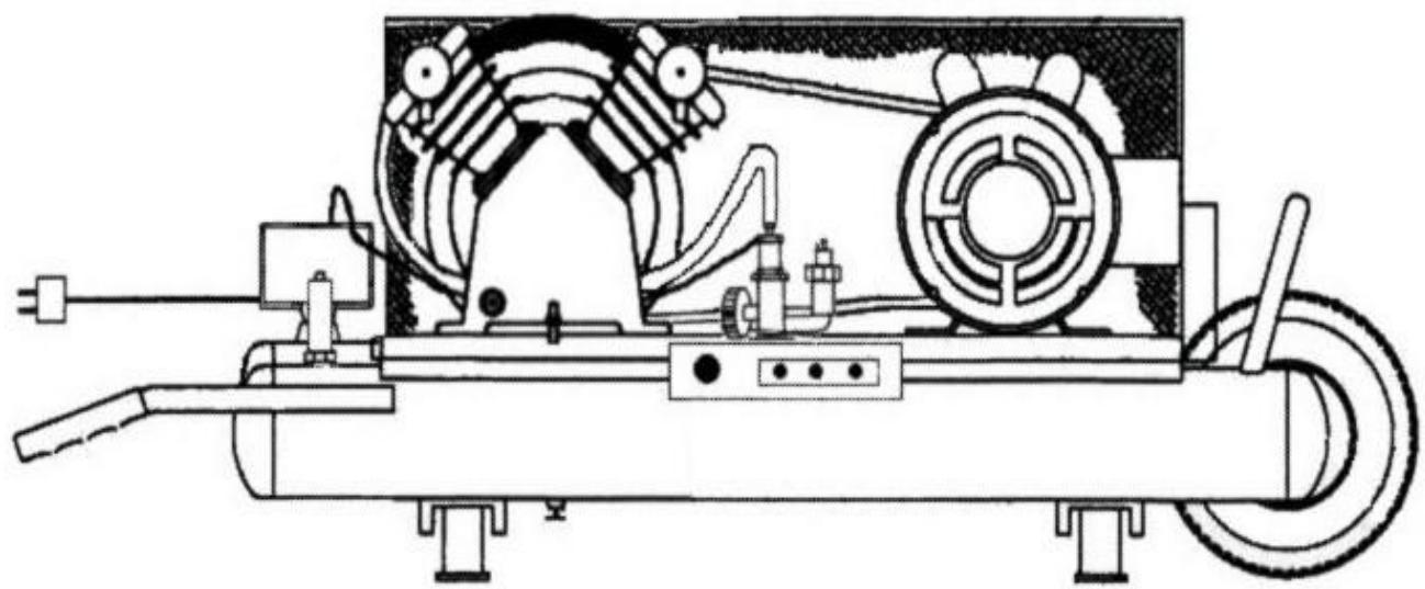
INSTALLATION
Proper care, maintenance and lubrication ensure longevity. The compressor should always be level for proper lubrication. Do not ever tighten foot bolts as excessive vibration may occur. Use only in a clean, dry, and well-ventilated area. The compressor has heat dissipation fins for proper cooling. Keep the fins and other parts that collect dust clean. Do not place rags or other materials on top of the compressor, as this obstructs cooling and can be a fire hazard.
BEFORE OPERATING THE AIR COMPRESSOR
PLEASE CHECK THE FOLLOWING CAREFULLY:
1) Check to see that nuts and bolts are all snug.
2) Check if the quantity and quality of oil is correct.
3) If the intake filters are dirty, they should be replaced or cleaned.
| Compressor oil | # EAOIL10 (1 Litre) |
| *Compressor originally filled with SAE 20W oil (ISO 68) | |
Compressor oil is a non-detergent mineral oil formulated with additives to help minimize carbon build up, increase ring life and reduce oil consumption, for use at ambient temperatures of 0^ to 30^ C ( 32^ - 86^ F).
OTHER APPROVED OILS
Regular mineral oils can also be used in this compressor. Always use non-detergent oil with the following specifications:
| AMBIENT TEMPERATURE AT POINT OF OPERATION | SAE VISCOSITY | ISO VISCOSITY |
| -16°C to 0°C (3.2°F to 32°F) | SAE 10W | ISO 32 |
| 1°C to 26°C (33.8°F to 78.8°F) | SAE 20W | ISO 68 |
| Above 27°C (80.6°F) | SAE 30W | ISO 100 |
OIL CHANGES
INITIAL OIL CHANGE DUE AT 100 HOURS
CHANGE OIL EVERY 300 HRS OR 3 MONTHS, WHICHEVER COMES FIRST.
1) Remove the oil drain plug. Allow oil to drain completely.
2) Replace the oil drain plug.
3) Refill with the recommended oil to the proper level.
Before doing any maintenance or adjustments to your air compressor, the following safety precautions should be taken:
- TURN OFF AND UNPLUG POWER CORD.
- DRAIN AIR RECEIVER AND AIR LINES OF AIR PRESSURE.
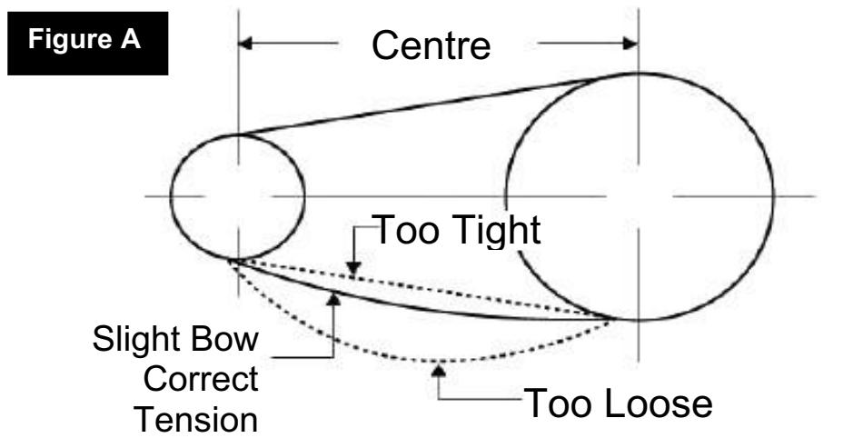
CHECKING BELT TENSION
Adjust belt(s) so when pressure is applied at the center, there is approx. 1 / 2" slack (see diagram below). If the belt is installed too tight, the motor might be overloaded. This will cause the motor to overheat. If the belt is installed too loosely, it will slip and excessive wear and vibration will occur.
HOW TO INSTALL NEW BELT IF REQUIRED
1) Disconnect power supply.
2) Remove belt guard.
3) Loosen motor bolts and slide motor toward compressor head just enough to allow old belt to be removed.
4) Install proper replacement belt.
5) Slide motor away from compressor head to provide recommended tension as shown in diagram on page 5.
6) Align belt using a straight edge ruler against pulley's edge.
7) Fasten motor bolts.
8) Ensure motor and compressor pulleys are secure. Re-check alignment.
9) Re-install belt guard and reconnect power supply.
10) Belt tension should be checked after 20 hours of operation. Check tension monthly thereafter.
OPERATING YOUR AIR COMPRESSOR
ELECTRIC DRIVE WITH DUAL CONTROL
1) Check unit for any damage.
2) Check compressor oil level, fill or add if necessary.
3) Pressure switch "Off/Auto" knob should be in "Off" position.
4) Plug in power cord to proper electrical outlet.
5) Stop/Start (pressure switch) control
a) Shut-off valve on pilot unloader should be closed ("knurled" knob on top of the pilot unloader should be turned all the way down).
b) Turn pressure switch "Off/Auto" switch to "Auto". Electric motor should now start and fill air receiver(s) with compressed air until cut-out pressure is reached. Compressor should stop and remain stopped until air receiver pressure reaches the cut-in pressure. The unit will continue to cycle in this automatic operation until it is turned off.
6) Continuous run (pilot unloader) control
a) Open the shut-off valve on pilot unloader ("knurled" knob on top of the pilot unloader should be turned all the way up).
b) Turn pressure switch "Off/Auto" switch to "Auto". Electric motor should now start and fill air receiver(s) with compressed air until full pressure is reached. To engage continuous run, turn "knurled" knob down. Your compressor will idle down and continue to idle once maximum pressure is achieved. When cut-in pressure is reached, the unloader valve will de-activate and unit will compress air. The unit will continue in this automatic operation until the unit is stopped ("Off/Auto" switch turn to the "Off" position and/or electric power supply is disconnected).
7) You can switch at anytime from Stop/Start to Continuous Run and vice versa by opening or closing the valve on the pilot unloader.
ELECTRIC DRIVE
1) Check unit for any damage.
2) Check compressor oil level, fill or add oil if necessary.
3) Pressure switch "Off/Auto" switch should be in "Off" position.
4) Plug in power cord to proper electrical outlet. If compressor is not equipped with a male plug, hire an electrician to install one.
OPERATING YOUR AIR COMPRESSOR
ELECTRIC DRIVE
5) Stop/Start pressure switch control
a) Turn pressure switch "Off/Auto" switch to "Auto". Electric motor should now start and fill air receiver(s) with compressed air until cut-out pressure is reached. Compressor should stop and remain stopped until air receiver pressure reaches the cut-in pressure. The unit will continue to cycle in this automatic operation until the pressure switch is turned to the "Off" position and/or electric power supply is disconnected).
MAINTENANCE SCHEDULE

EXTRA CARE SHOULD BE TAKEN TO AVOID PERSONAL INJURIES WITH AUTOMATICALLY CONTROLLED COMPRESSORS
Check oil level
Drain condensation from air receiver(s)
Check for any unusual noise or vibration
Be sure all nuts and bolts are tight
WEEKLY
Turn off power. Clean dust and foreign matter from cylinder heads, motor, fan blades, intercooler and air receiver(s)
Clean air filter by opening air filter, removing filter element and cleaning it thoroughly with soapy water. Rinse thoroughly and allow to dry completely before assembly.
Worn filters should be replaced
Check V-belts for wear
MAINTENANCE SCHEDULE
MONTHLY
Inspect unit for leaks
Tighten joints if leaks are observed
Check V-belt for proper tension
Check compressor pulley and motor sheave are aligned and securely fastened (see item 8)
QUARTERLY
Inspect the air receiver for corrosion or other damage
Change compressor oil
Replace air filters (more often if compressor is used near paint spraying operations or in dusty environments).
TROUBLESHOOTING GUIDE
| PROBLEM | POSSIBLE CAUSE | CORRECTIVE ACTION |
| Will not start | Check power supply | Make sure power is turned on |
| Check motor reset button | Depress motor reset button | |
| Low pressure | Safety valve leaks | Replace safety valve |
| Drain cock open | Close drain cock | |
| Loose tubes or fittings | Tighten fittings | |
| Dirty or plugged air filter | Clean or replace as necessary | |
| Defective unloader valve | Replace unloader valve | |
| Oil in discharge | Improper oil viscosity | Drain and replace oil |
| Too much oil in the crankcase | Drain oil and fill to proper level | |
| Compressor overheated | Air pressure regulated too high | |
| Restricted air filter | Clean or replace air filter | |
| Worn piston rings | Replace piston rings |
TROUBLESHOOTING GUIDE
| PROBLEM | POSSIBLE CAUSE | CORRECTIVE ACTION |
| Compressor Overheats | Clogged inlet filter | Clean or replace as necessary |
| Dirty compressor, head, cylinder, intercooler | Clean with compressed air | |
| Operating pressure too high | Reduce operating pressure | |
| Low oil or wrong oil being used | Drain and replace oil | |
| Compressor cycle too long, proper cycle is 50 to 60% on Stop/Start operation and 75 to 80% on continuous run operation | Allow for longer rest between cycles | |
| Compressor loads and unloads or stops and starts excessively | Leaks in air system | Replace worn components as necessary |
| Worn or loose drive belts | Tighten V-belts or replace | |
| Pilot valve or pressure switch differential adjustment too close | Make necessary adjustments | |
| Defective compressor valves | Replace valves | |
| Compressor too small for intended use | ||
| Water in crankcase, oil breaking up, oil gets dirty, rusty valves or cylinder(s) | Cycle too short; compressor does not operate long enough to vaporize condensed moisture during compression | Allow for a longer operating cycle |
| Compressor operating outside in cold conditions or inlet filter not protected against weather | Provide adequate protection against extreme weather conditions | |
| System pressure leaking back through check valve when compressor is stopped | Check and replace check valve if necessary | |
| Wrong oil being used | Drain and replace with proper oil |
TROUBLESHOOTING GUIDE
| PROBLEM | POSSIBLE CAUSE | CORRECTIVE ACTION |
| Insufficient output, low discharge pressure | Clogged inlet filter | Clean or replace as necessary |
| Leaks in air lines, air valves, fittings, etc... | Replace worn components as necessary | |
| Drive belts slipping | Tension V-belts | |
| Drain valve left open | Close drain valve | |
| Defective pressure gauge | Replace pressure gauge | |
| Compressor incorrectly sized | ||
| Leaking head gasket | Replace head gasket | |
| Dirty or plugged inter cooler tubes | Remove and clean inter cooler tubes | |
| Unloader pilot or pressure switch adjustment too low, or defective | Make necessary adjustments | |
| Worn or defective compressor valves | Replace worn parts | |
| Worn piston, worn out rings | Replace worn parts | |
| Restrictive check valve | Clean check valve and replace if necessary | |
| Motor stalls | Faulty unloader/check valve | Replace unloader or check valve |
| Valves incorrectly installed | Install valves correctly | |
| Drive belts too tight | Tension V-belts | |
| Compressor knocks | Compressor valves loose or broken | Check and replace worn or broken valves |
| Inspect check valve, it may knock at low pressures | Remove and clean check valve | |
| Piston rings not seated | Compressor not run long enough to seat rings | Allow 100 hours of normal operation for new rings to seat |
| Wrong oil being used, wrong viscosity | Drain and replace with proper oil |
TROUBLESHOOTING GUIDE
| PROBLEM | POSSIBLE CAUSE | CORRECTIVE ACTION |
| Excessive vibration | Loose compressor, motor, or guard | Tighten components |
| Excessive discharge pressure | Reduce operating pressure | |
| Compressor not level | Level compressor | |
| Leg bolts tightened too tightly to floor | Loosen leg bolts | |
| Wrong oil being used | Drain and replace with proper oil | |
| Loose flywheel, drive pulley or drive belts | Tighten loose components and check belts | |
| Worn rods, wrist pin or main bearings | Check and replace worn parts | |
| Compressor uses too much oil | Clogged inlet filter | Clean inlet filter or replace if necessary |
| Wrong oil being used, wrong viscosity | Drain and replace with proper oil | |
| Oil level too high | Fill compressor with oil to proper level | |
| Crankcase breather valve malfunction | Replace crankcase breather | |
| Compressor operating outside in cold conditions or inlet filter not protected against weather | Provide adequate protection against extreme weather conditions | |
| Worn piston rings | Replace piston rings | |
| Piston rings not seated | Allow for 100hrs of normal operation for rings to seat | |
| Compressor runs unloaded too long | Increase load or stop compressor when not needed (check for air leaks) |
COMPRESSOR MAINTENANCE LOG
| DATE | TYPE OF MAINTENANCE OR REPAIR |
FACTORY SERVICE CENTERS
| HEAD OFFICE | REGIONAL OFFICE | REGIONAL OFFICE |
| 1950 Forbes Street | 11771 Hammersmith Way | 6389 boul. Couture |
| Whitby, ON L1N 7B7 | Richmond, BC V7A 5H6 | St. Leonard, PQ H1P 3J5 |
| (905) 571-2200 | (604) 272-3104 | (514) 323-1223 |
| 1-800-263-3734 | 1-800-663-0909 | 1-800-361-7049 |
| Alberta | Nova Scotia | Quebec |
| #8 – 6115 4thSt. S.E. | 202 Brownlow Avenue | 1140 rue Begin |
| Calgary, AB T2H 2H9 | Dartmouth, NS B3B 1T5 | St. Laurent, PQ H4R 1X1 |
| (403) 243-3995 | (902) 468-7064 | (514) 745-5025 |
| 1-800-267-0445 | 1-800-625-4821 | 1-888-745-5025 |
| Ontario | 1200 St. Jean Baptiste, | |
| 11614 – 149thStreet | 1950 Forbes Street | Unit # 106 |
| Edmonton, AB T5M 3R5 | Whitby, ON L1N 7B7 | Les Saules, PQ G2E 5E8 |
| (780) 455-6644 | (905) 571-2200 | (418) 871-5720 |
| 1-888-455-6644 | 1-800-263-3734 | 1-800-663-5757 |
| British Columbia | 6389 boul. Couture | |
| 11771 Hammersmith way | 6350 Tomken Rd, Unit B | St. Leonard, PQ H1P 3J5 |
| Richmond, BC V7A 5H6 | Mississauga, ON L5T 1Y3 | (514) 323-1223 |
| (604) 272-3104 | (905) 670-7255 | 1-800-361-7049 |
| 1-800-663-0909 | 1-800-221-9811 | |
| Saskatchewan | ||
| 2284 Holdom Ave | 210 Colonnade Rd., Unit 11 | 206A-2750 Faithful Ave |
| Burnaby, BC V5B 4Y5 | Nepean (Ottawa), ON K2E 7K5 | Saskatoon, SK S7K 6M6 |
| (604) 291-1511 | (613) 224-5022 | (306) 931-0111 |
| 1-877-295-1511 | 1-888-560-2214 | 1-888-931-0111 |
| Manitoba | ||
| 1670 St. James Street | 317 Adelaide St. S. Unit 117 | |
| Winnipeg, MB R3H 0L3 | London, ON N5Z 3L3 | |
| (204) 694-0402 | (519) 686-3115 | |
| 1-800-550-5073 | 1-800-571-0899 |
| When you need service: Send complete tool (prepaid) to one of the Makita Factory Service Centers listed, or to an Authorized Makita Service Center. Be sure to attach a letter to the outside of the carton detailing the problem with your tool. | Date Purchased: |
| Dealer's Name and Address: | |
| Model No: | |
| Serial No: |
MAKITA WARRANTY
MAKITA LIMITED ONE YEAR WARRANTY
WARRANTY POLICY
Every Makita tool is thoroughly inspected and tested before leaving the factory. It is warranted to be free of defects from workmanship and materials for the period of ONE YEAR from the date of original purchase. Should any trouble develop during this one year period, return the COMPLETE tool, freight prepaid, to one of Makita's Factory or Authorized Service Centers. If inspection shows the trouble is caused by defective workmanship or material, Makita will repair, (or at our option, replace) without charge.
This warranty does not apply where:
- Repairs have been made or attempted by others;
- Repairs are required because of normal wear and tear;
- The tool has been abused, misused or improperly maintained;
- Alterations have been made to the tool.
IN NO EVENT SHALL MAKITA BE LIABLE FOR ANY INDIRECT, INCIDENTAL OR CONSEQUENTIAL DAMAGES FROM THE SALE OR USE OF THE PRODUCT. THIS DISCLAIMER APPLIES BOTH DURING AND AFTER THE TERM OF THIS WARRANTY.
- The Makita warranty is the only and entire written warranty given by Makita for Makita tools. No dealer or his agent or employee is authorized to extend or enlarge upon this warranty by any verbal or written statement or advertisement.
MAKITA DISCLAIMS LIABILITY FOR ANY IMPLIED WARRANTYES, INCLUDING WARRANTYES OF "MERCHANTABILITY" AND "FITNESS FOR A SPECIFIC PURPOSE," AFTER THE ONE YEAR TERM OF THIS WARRANTY.
This warranty gives you specific legal rights. The provisions contained in this warranty are not intended to limit, modify, take away from, disclaim or exclude any warranties set forth in any provincial legislation. To the extent required by law, the provisions in any provincial or federal legislation with respect to warranties take precedence over the provisions in this warranty.
Makita Canada Inc.
1950 Forbes Street
Whitby, ON L1N 7B7
thakita
Compresseur
Portatif
Électrique
NE PAS ENLEVER, ALTERER OU REMPLACER CETTE SOUPAPE!
INSTALLATION ET OPÉRATION
RALLONGES ÉLECTRIQUES
PV01A
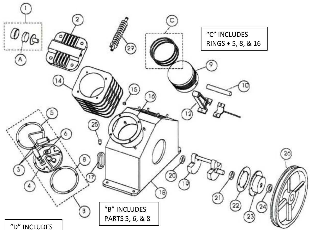
"D" INCLUDES PARTS 3,4, & 6
| Item | Description | Part # | Qty |
| 1 | intake filter assembly | MF2-RET | 2 |
| 2 | cylinder head | 51121-0101 | 2 |
| 3 | lift limiter - discharge valve plate | 51121-3102 | 2 |
| 4 | valve seat | 51121-2101 | 2 |
| 5 | valve seat to head gasket | 51121-2105 | 2 |
| 6 | discharge valve plate | 51121-2103 | 4 |
| 8 | valve seat to cylinder gasket | 51121-2104 | 2 |
| 9 | piston | 52121-5101 | 2 |
| 10 | piston pin c/w snap rings | 51121-5112 | 2 |
| 12 | connecting rod c/w dipper | 51121-5120 | 2 |
| 14 | cylinder | 52121-4101 | 2 |
| 15 | oil filler cap | 51111-4719 | 1 |
| 16 | cylinder to crankcase gasket | 51121-4103 | 2 |
| 17 | oil sight glass c/w gasket | 51111-4770 | 1 |
| 18 | crankcase | 51121-4701 | 1 |
| 19 | crankshaft | 51121-4601 | 1 |
| 20 | front bearing | 83501-6205 | 1 |
| 21 | rear bearing | 83501-6204 | 1 |
| 22 | crankcase to rear bearing housing gasket | 51121-4704 | 1 |
| 23 | rear bearing housing | 51121-4703 | 1 |
| 24 | oil seal | 51121-4708 | 1 |
| 25 | crankcase breather | 51111-4761 | 1 |
| 26 | flywheel c/w fasteners | 51121-6601 | 1 |
| 29 | connecting (interstage) tubing | 51121-7710 | 1 |
| Misc. | 1/4" street elbow (oil drain) | STREL1/4 | 1 |
| Misc. | rear bearing snap ring | 83610-113025 | 1 |
| Misc. | interstage "Y" fitting | 51121-7710 | 1 |
| Misc. | interstage "elbow" fitting | 51112-7701 | 1 |
| A | Intake filter element kit includes one (1) intake filter element | MAIF35E | 2 |
| B | Valve repair kit includes: Valve seat to head gasket (item 5) Two(2) outlet valve plates (item 6) Intake valve plate (item 7) Six(6) valve plate screws Valve seat to cylinder gasket (item 8) | 101000-151 | 2 |
| C | Ring repair kit includes: Valve seat to head gasket (item 5) Valve seat to cylinder gasket (item 8) Two(2) compression rings One(1) oil control ring Cylinder to crankcase gasket (item 16) | 101000-255 | 2 |
| D | Valve plate assembly (not shown) | 51121-2100 | 2 |
Certificate of Warranty / Certificate de garantie
Mail to Makita / Envoyer a Makita
Date Purchased / Date de I'achat:

Month / Mois

Day / Jour

Year / Année
Dealer's name and address /
- OWNERS MANUAL FOR
- Oil Lubricated Air Compressor
- SPECIFICATION CHART
- MAC3001
- TABLE OF CONTENTS
- SPECIFICATION CHART 2
- SAFETY PRECAUTIONS 5
- INSTALLATION & OPERATION INSTRUCTIONS 6
- OPERATING YOUR AIR COMPRESSOR 9
- MAINTENANCE SCHEDULE 10
- TROUBLESHOOTING GUIDE 11
- MAINTENANCELOG 15
- MAKITA WARRANTY 17
- FACTORY SERVICE CENTERS 16
- PARTS BREAKDOWNS 38
- SAFETY PRECAUTIONS
- CAUTIONS
- CAUTION
- WARNING
- AIR RECEIVER
- NEVER WELD, DRILL OR CHANGE THE AIR RECEIVER IN ANY WAY
- SAFETY VALVE
- Adjustment by user will automatically Void the warranty.
- DO NOT REMOVE, MAKE ADJUSTMENTS TO OR SUBSTITUTE THIS VALVE!
- INSTALLATION
- BEFORE OPERATING THE AIR COMPRESSOR
- PLEASE CHECK THE FOLLOWING CAREFULLY:
- OTHER APPROVED OILS
- OIL CHANGES
- INITIAL OIL CHANGE DUE AT 100 HOURS
- CHECKING BELT TENSION
- HOW TO INSTALL NEW BELT IF REQUIRED
- OPERATING YOUR AIR COMPRESSOR
- ELECTRIC DRIVE WITH DUAL CONTROL
- ELECTRIC DRIVE
- 5) Stop/Start pressure switch control
- MAINTENANCE SCHEDULE
- EXTRA CARE SHOULD BE TAKEN TO AVOID PERSONAL INJURIES WITH AUTOMATICALLY CONTROLLED COMPRESSORS
- WEEKLY
- MONTHLY
- QUARTERLY
- TROUBLESHOOTING GUIDE
- COMPRESSOR MAINTENANCE LOG
- MAKITA WARRANTY
- MAKITA LIMITED ONE YEAR WARRANTY
- WARRANTY POLICY
- thakita
- Compresseur
- Portatif
- Électrique
- NE PAS ENLEVER, ALTERER OU REMPLACER CETTE SOUPAPE!
- INSTALLATION ET OPÉRATION
- RALLONGES ÉLECTRIQUES
- Certificate of Warranty / Certificate de garantie
Brand : MAKITA
Model : MAC3001
Category : Compressor