
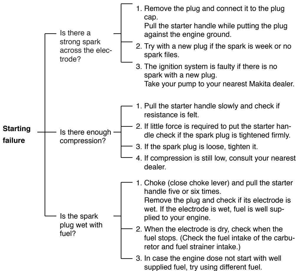
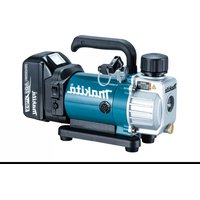
EW220R - Water pump MAKITA - Free user manual and instructions
Find the device manual for free EW220R MAKITA in PDF.
| Product type | Thermal water pump |
| Brand | Makita |
| Model | EW220R |
| Engine | Single-cylinder 4-stroke, 212 cc |
| Maximum power | 5.5 kW (7.5 hp) |
| Flange diameter | 50 mm (2 inches) |
| Maximum flow rate | 15 m³/h |
| Maximum delivery head | 30 m |
| Maximum suction head | 8 m |
| Fuel tank capacity | 3.6 L |
| Oil sump capacity | 0.6 L |
| Dimensions (L × W × H) | 510 × 380 × 430 mm |
| Weight (dry) | 25 kg |
| Fuel | Unleaded gasoline |
| Recommended engine oil | SAE 10W-30 (4-stroke) |
| Main functions | Clear water pumping, irrigation, basin drainage, water transfer |
| Routine maintenance | Oil change, air filter cleaning, spark plug replacement |
| Safety | Automatic shut-off for low oil level (optional), spark arrester (optional) |
| Spare parts | Available through Makita network or authorized dealers |
| Repairability | Repairability index: 7.5/10 (rated by users) |
Frequently Asked Questions - EW220R MAKITA
User questions about EW220R MAKITA
0 question about this device. Answer the ones you know or ask your own.
Ask a new question about this device
Download the instructions for your Water pump in PDF format for free! Find your manual EW220R - MAKITA and take your electronic device back in hand. On this page are published all the documents necessary for the use of your device. EW220R by MAKITA.
USER MANUAL EW220R MAKITA
natural_image
Technical line drawing of a mechanical pump assembly (no text or labels)INSTRUCTIONS FOR USE
MANUEL D'UTILISATION
!
WARNING:
!
The engine exhaust from this product contains chemicals known to the State of California to cause cancer, birth defects or other reproductive harm.
NOTICE
FEDERAL EMISSION COMPONENT DEFECT WARRANTY and CALIFORNIA EMISSION CONTROL WARRANTY are applicable to only those engines/generators complied with EPA (Environmental Protection Agency) and CARB (California Air Resources Board) emission regulations in the U.S.A.
NOTICE
To the engines/generators exported to and used in the countries other than the U.S.A., warranty service shall be performed by the distributor in each country in accordance with the standard engine/generator warranty policy as applicable.
AIR INDEX
To show compliance with California emission regulations, a hangtag has been provided displaying the Air Index level and durability period of this engine.
The Air Index level defines how clean an engine's exhaust is over a period of time. A bar graph scaled from "0" (most clean) to "10" (least clean) is used to show an engine's Air Index level. A lower Air Index level represents cleaner exhaust from an engine.
The period of time (in hours) that the Air Index level is measured is known as the durability period. Depending on the size of the engine, a selection of time periods can be used to measure the Air Index level (see below).
Descriptive Term Applicable to Emissions Durability Period
| Moderate | - | 50 hours (engine from 0 to 80 cc)125 hours (engine greater than 80 cc) |
| Intermediate | - | 125 hours (engine from 0 to 80 cc)250 hours (engine greater than 80 cc) |
| Extended | - | 300 hours (engine from 0 to 80 cc)500 hours (engine greater than 80 cc) |
Notice : This hangtag must remain on this engine or piece of equipment, and only be removed by the ultimate purchaser before operation.
FEDERAL EMISSIONS COMPONENT DEFECT WARRANTY
EMISSIONS COMPONENT DEFECT WARRANTY COVERAGE - This emission warranty is applicable in all States, except the State of California
Makita U.S.A. Inc., La Mirada, California, (herein "MAKITA") warrant(s) to the initial retail purchaser and each subsequent owner, that this Nonroad engine (herein "engine") has been designed, built, and equipped to conform at the time of initial sale to all applicable regulations of the U.S. Environmental Protection Agency (EPA), and that the engine is free of defects in materials and workmanship which would cause this engine to fail to conform with EPA regulations during its warranty period.
For the components listed under PARTS COVERED, the Makita Factory Service Center or Service Center authorized by MAKITA will, at no cost to you, make the necessary diagnosis, repair, or replacement necessary to ensure that the engine complies with applicable U.S. EPA regulations.
EMISSION COMPONENT DEFECT WARRANTY PERIOD
The warranty period for this engine begins on the date of sale to the initial purchaser and continues for a period of 2 years.
PARTS COVERED
Listed below are the parts covered by the Emission Components Defect Warranty. Some of the parts listed below may require scheduled maintenance and are warranted up to the first scheduled replacement point for that part.
(1) Fuel Metering System
(i) Carburetor and internal parts (and/or pressure regulator or fuel injection system).
(ii) Air/fuel ratio feedback and control system, if applicable.
(iii) Cold start enrichment system, if applicable.
(iv) Regulator assy (gaseous fuel, if applicable)
(2) Air Induction System
(i) Intake manifold, if applicable
(ii) Air filter.
(3) Ignition System
(i) Spark plugs.
(ii) Magneto or electronic ignition system.
(iii) Spark advance/retard system, if applicable.
(4) Exhaust manifold, if applicable
(5) Miscellaneous Items Used in Above Systems
(i) Electronic controls, if applicable
(ii) Hoses, belts, connectors, and assemblies.
(iii) Filter lock assy (gaseous fuel, if applicable)
OBTAINING WARRANTY SERVICE
To obtain warranty service, take your engine to the nearest Makita Factory Service Center or Service Center authorized by MAKITA. Bring your sales receipts indicating date of purchase for this engine. The Makita Factory Service Center or Service Center authorized by MAKITA will perform the necessary repairs or adjustments within a reasonable amount of time and furnish you with a copy of the repair order. All parts and accessories replaced under this warranty become the property of MAKITA.EPA - MAKITA FEDERAL EMISSIONS COMPONENT DEFECT WARRANTY-continued
WHAT IS NOT COVERED
*Conditions resulting from tampering, misuse, improper adjustment (unless they were made by the Makita Factory Service Center or Service Center authorized by MAKITA during a warranty repair), alteration, accident, failure to use the recommended fuel and oil, or not performing required maintenance services.
*The replacement parts used for required maintenance services.
*Consequential damages such as loss of time, inconvenience, loss of use of the engine orequipment, etc.
*Diagnosis and inspection charges that do not result in warranty-eligible service being performed.
*Any non-authorized replacement part, or malfunction of authorized parts due to use of non-authorized parts.
OWNER'S WARRANTY RESPONSIBILITIES
As the engine owner, you are responsible for the performance of the required maintenance listed in your owner's manual. MAKITA recommends that you retain all receipts covering maintenance on your engine, but MAKITA cannot deny warranty solely for the lack of receipts or for your failure to ensure the performance of all scheduled maintenance.
As the engine owner, you should however be aware that MAKITA may deny warranty coverage if your engine or a part has failed due to abuse, neglect, improper maintenance or unapproved modifications.
You are responsible for presenting your engine to the nearest Makita Factory Service Center or Service Center authorized by MAKITA when a problem exists.
If you have any questions regarding your warranty rights and responsibilities, you should contact the Makita Warranty Department at 1-800-4-MAKITA for the information.
THINGS YOU SHOULD KNOW ABOUT THE EMISSION CONTROL SYSTEM WARRANTY MAINTENANCE AND REPAIRS
You are responsible for the proper maintenance of the engine. You should keep all receipts and maintenance records covering the performance of regular maintenance in the event questions arise. These receipts and maintenance records should be transferred to each subsequent owner of the engine. MAKITA reserves the right to deny warranty coverage if the engine has not been properly maintained. Warranty claims will not be denied, however, solely because of the lack of required maintenance or failure to keep maintenance records.
MAINTENANCE, REPLACEMENT OR REPAIR OF EMISSION CONTROL DEVICES AND SYSTEMS MAY BE PERFORMED BY ANY REPAIR ESTABLISHMENT OR INDIVIDUAL ; HOWEVER, WARRANTY REPAIRS MUST BE PERFORMED BY THE MAKITA FACTORY SERVICE CENTER OR SERVICE CENTER AUTHORIZED BY MAKITA. THE USE OF PARTS THAT ARE NOT EQUIVALENT IN PERFORMANCE AND DURABILITY TO AUTHORIZED PARTS MAY IMPAIR THE EFFECTIVENESS OF THE EMISSION CONTROL SYSTEM AND MAY HAVE A BEARING ON THE OUTCOME OF A WARRANTY CLAIM.
If other than the parts authorized by MAKITA are used for maintenance replacements or for the repair of components affecting emission control, you should assure yourself that such parts are warranted by their manufacturer to be equivalent to the parts authorized by MAKITA in their performance and durability.
HOW TO MAKE A CLAIM
All repair qualifying under this limited warranty must be performed by a Makita Factory Service Center or Service Center authorized by MAKITA. In the event that any emission-related part is found to be defective during the warranty period, you shall notify Makita Warranty Department at 1-800-4-MAKITA and you will be advised of the appropriate warranty service dealer or service providers where the warranty repair can be performed. A list of the Factory Service Center locations and phone numbers is provided below for your convenience.
ARIZONA
3707 E.Broadway Rd., Ste.6
Phoenix, AZ 85040
(602) 437-2850
CALIFORNIA
41850 Christy St.
Fremont, CA 94538-5107
(510)657-9881
14930 Northam St.
La Mirada, CA 90638-5753
(714)522-8088
4191A Power Inn Rd.
Sacramento, CA 95826
(916) 454-4768
7674 Clairemont Mesa Blvd.
San Diego, CA 92111
(858)278-4471
16735 Saticoy St., Ste. 105
Van Nuys, CA 91406
(818)782-2440
COLORADO
11809 E.51st Ave.
Denver, CO 80239-2709
(303) 371-2850
FLORIDA
750 East Sample Rd.
Pompano Beach, FL 33064
(954)781-6333
GEORGIA
4680 River Green Parkway NW
Duluth, GA 30096
(770) 476-8911
ILLINOIS
1450 Feehanville Dr.
Mt. Prospect, IL 60056-6011
(847) 297-3100
MARYLAND
7397 Washington Blvd Ste 104
Elkridge, MD 21075
(410) 796-4401
MASSACHUSETTS
232 Providence Highway
Westwood, MA 02090
(781) 461-9754
MINNESOTA
6427 Penn Ave. South
Richfield, MN 55423
(612) 869-5199
MISSOURI
9876 Watson Rd.
St.Louis, MO 63126-2221
(314) 909-9889
NEBRASKA
4129 S. 84th St.
Omaha, NE 68127
(402) 597-2925
NEVADA
3375 S. Decatur Blvd., Suites22-24
Las Vegas, NV 89102
(702) 368-4277
NEW JERSEY
251 Herrod Blvd.
Dayton, NJ 08810-1539
(609) 655-1212
NEW YORK
4917 Genessee St.
Cheektowaga, NY 14225
(716) 685-9503
OREGON
828 19th Ave., N. W.
Portland, OR 97209
(503) 222-1823
PENNSYLVANIA
1904 Babcock Blvd.
Pittsburgh, PA 15209
(412)822-7370
PUERTO RICO
200 Guayama St.
Hato Rey, PR 00917
(787) 250-8776
TENNESSEE
1120 Elm Hill Pike Suite 170
Nashville, TN 37210
(615)248-3321
TEXAS
Farmers Branch, TX 75234
(972) 243-1150
4321 W. Sam Houston Pkwy
Suite 130
Houston, TX 77043
(713) 983-8034
3453 IH-35 North, Ste. 101
San Antonio, TX 78219
(210) 228-0676
WISCONSIN
Lincoln Plaza Shopping Ctr.
2245 S. 108th St.
West Allis, WI 53227
(414) 541-4776
CALIFORNIA EMISSION CONTROL WARRANTY STATEMENT (This warranty does not apply in any other state.) YOUR WARRANTY RIGHTS AND OBLIGATIONS
The California Air Resources Board and Makita U.S.A., Inc. (herein "MAKITA") are pleased to explain the emission control warranty on your 2005 and later small off-road engine (herein "engine"). In California, new engine must be designed, built and equipped to meet the State's stringent anti-smog standards. MAKITA must warrant the emission control system on your engine for the periods of time listed below provided there has been no abuse, neglect or improper maintenance of your engine.
Your emission control system includes parts such as the carburetor or fuel injection systems, the ignition system and the catalytic converter. Also included are the hoses, belts, connectors and other emission-related assemblies.
Where a warrantable condition exists, MAKITA will repair your engine at no cost to you including diagnosis, parts and labor.
MANUFACTURER'S WARRANTY COVERAGE :
The 2005 and later engines are warranted for two years. If any emission-related part on your engine is defective, the part will be repaired or replaced by MAKITA.
OWNER'S WARRANTY RESPONSIBILITIES :
-As the engine owner, you are responsible for the performance of the required maintenance listed in your Owner's Manual. MAKITA recommends that you retain all receipts covering maintenance on your engine, but MAKITA cannot deny warranty solely for the lack of receipts or for your failure to ensure the performance of all scheduled maintenance.
-As the engine owner, you should be aware, however, that MAKITA may deny you warranty coverage if your engine or a part has failed due to abuse, neglect, improper maintenance or unapproved modifications.
-You are responsible for presenting your engine to a MAKITA service center as a problem exists.
The warranty repairs should be completed in a reasonable time, not to exceed 30 days.
If you have any questions regarding your warranty rights and responsibilities, you should contact a Makita Factory Service Center Manager nearest you. A list of the Factory Service Center locations and phone numbers is provided below for your convenience.
LIMITED WARRANTY on Emission Control Systems – California Only –
MAKITA, a distributor of small off-road equipment in the U.S., warrants to the owner of 2005 and later engines that the engine (1) has been designed, built, and equipped at the time of manufacture so as to conform with the applicable regulations of the California Air Resources Board and, (2) is free from defects in materials and workmanship which may cause it to fail to conform with those regulations as applicable according to the terms and conditions stated below.
WARRANTY PERIOD
This warranty period begins on the date which the engine is delivered to the original retail purchaser and ends two years after that date. During this two year period MAKITA warrants to the original retail purchaser and each subsequent purchaser that the engine is free from defect in material and workmanship that can cause the failure of a warranted emission-related part.
WHAT IS COVERED UNDER THIS WARRANTY
Repair and/or replacement of any warranted emission-related part will be performed at no charge provided the work is performed at an authorized warranty station. There will also be no charge for any diagnostic labor performed at an authorized warranty station which leads to the determination that a warranted emission-related part is defective.
Any warranted part which is not scheduled for replacement as required maintenance, or which is scheduled only for regular inspection to the effect of "repair or replace as necessary" shall be warranted for the warranty period. Any warranted part which is scheduled for replacement as required maintenance shall be warranted for the period of time up to the first scheduled replacement of that part. This warranty shall apply only towards the repair, replacement, and/or adjustment of the component parts listed below.
EMISSION-RELATED PARTS COVERED UNDER THIS WARRANTY
(1) Fuel Metering System
(i) Carburetor and internal parts (and/or pressure regulator or fuel injection system).
(ii) Air/fuel ratio feedback and control system, if applicable.
(iii) Cold start enrichment system, if applicable.
(iv) Regulator assy (gaseous fuel, if applicable)
(2) Air Induction System
(i)Intake manifold, if applicable
(ii) Air filter.
(3) Ignition System
(i) Spark plugs.
(ii) Magneto or electronic ignition system.
(iii) Spark advance/retard system, if applicable.
(4) Exhaust manifold, if applicable
(5) Miscellaneous Items Used in Above Systems
(i) Electronic controls, if applicable
(ii) Hoses, belts, connectors, and assemblies.
(iii) Filter lock assy (gaseous fuel, if applicable)
If it is determined by an authorized warranty station that other engine components have been damaged due to the failure of a warranted emission-related part during the warranty period, MAKITA will repair and/or replace the necessary components.
WHAT IS NOT COVERED UNDER THIS WARRANTY
This warranty does not cover any emission-related part which malfunctions, fails, or is damaged due to alterations and/or modifications such as changing, adding, or removing parts.
When an engine is being serviced under warranty, MAKITA and any of its authorized dealers, distributors, or warranty stations shall not be liable for any loss of use of the engine, for any damage to goods, or loss of time or inconvenience. This limited warranty also does not apply to any emission-related part which malfunctions, fails, or is damaged due to failure to follow the maintenance and operating instructions specified in the 2005 and later Owner's Manual including.
(a) Improper or inadequate maintenance of any warranted emission-related part.
(b) Improper installation, adjustment, or repair of the engine or any warranted emission-related part unless performed by a factory authorized warranty station.
(c) Failure to use recommended fuel as specified in the 2005 and later Owner's Manual.
(d) Repairs and diagnosis performed outside of an authorized warranty station.
(e) Use of parts which are not authorized by MAKITA.
MAINTENANCE SCHEDULE
The engine owner is responsible for having all scheduled inspection and maintenance services performed at the intervals specified in the 2005 and later Owner's Manual and to retain records of these services as having been performed. These records should be transferred to each subsequent owner of the engine. MAKITA cannot deny a claim solely because there are no records of scheduled maintenance, however, a warranty claim may be denied if the failure to perform the scheduled maintenance and inspection resulted in the failure of a warranted emission-related part.
As a minimum, the engine owner is responsible for the scheduled inspection and maintenance described below which are based on the procedures described in the Owner's Manual.
PROCEDURE
1) Change engine oil
2) Clean air cleaner (element)
3) Replace air cleaner element
4) Clean and adjust spark plug and electrodes
: Initial 20 hours and every 100 hours afterward
: Every 50 hours
: Every 200 hours
: Every 200 hours
INTERVAL
Note: More frequent maintenance may be necessary under dusty, dirty or severe conditions.
REPAIR AND REPLACEMENT OF EMISSION-RELATED PARTS
It is recommended that only engine replacement parts which have been authorized and approved by MAKITA should be used in the performance of any warranty maintenance or repairs of emission-related parts. These replacement parts will be provided at no charge if the part is still under warranty.
HOW TO FILE A WARRANTY CLAIM AND WHERE TO GET WARRANTY SERVICES
Contact the nearest Makita Factory Service Center Manager to determine the appropriate location where the required warranty services are to be performed. A list of the Factory Service Center locations and phone numbers are provided below for your convenience.
41850 Christy Street
Fremont, CA 94538-5107
(510)657-9881
7674 Clairemont Mesa Blvd.
San Diego, CA 92111
(619)278-4471
1421 N. Clovis Ave., Ste. 112
Fresno, CA 93727
(209)252-5166
1714 E. McFadden Ave., Unit M
Santa Ana, CA 92705
(714)667-5066
14930 Northam Street
La Mirada, CA 90638-5753
(714)522-8088
333 Littlefield Ave.
South San Francisco, CA 94080
(415)875-1002
1970 Fulton Avenue
Sacramento, CA 95825
(916)482-5197
16735 Saticoy St., Ste. 105
Van Nuys, CA 91406
(818) 782-2440
1440 South "E" Street
San Bernardino, CA 92408
(909)885-1289
FACTORY SERVICE CENTERS IN CANADA
BRITISH COLUMBIA
RICHMOND
(Vancouver Regional Office)
11771 Hammersmith Way, Richmond, V7A.5H6
Tel. 1.800.663.0909 or 604.272.3104
Fax.604.272.5416
COQUITLAM
Unit 103. 2131 Hartley Avenue, Coquitlam, V3K.2Z3
Tel. 604.525.7434 or 1.800.266.7738
Fax.604.525.7435
ALBERTA
CALGARY
8-6115 Fourth Street S.E., Calgary, T2H.2H9
Tel. 1.800.267.0445 or 403.243.3995
Fax.403.287.3044
EDMONTON
11614-149 Street, Edmonton, T5M.3R3
Tel. 1.888.455.6644 or 780.455.6544
Fax.780.451.4877
SASKATCHEWAN
SASKATOON
206A-2750 Faithful Avenue, Saskatoon, S7K.6M6
Tel. 1.888.931.0111 or 306.931.0111
Fax.306.931.4574
MANITOBA
WINNIPEG
1670 St. James Street, Winnipeg, R3H.0L3
Tel. 1.800.550.5073 or 204.694.0402
Fax.204.694.5782
ONTARIO
LONDON
317 Adelaide Street S., Unit 117, London, N5Z.3L3
Tel. 1.800.571.0899 or 519.686.3115
Fax.519.686.4347
MISSISSAUGA
6350 Tomken Road, Unit 8 Mississauga, L5T.1Y3
Tel. 1.888.221.9811 or 905.670.7255
Fax.905.670.0120
OTTAWA (Nepean)
210 Colonnade Road S, Unit #10, Ottawa (Nepean), K2E.7L5
Tel. 1.888.560.2214 or 613.224.5022/5088
Fax.613.224.2360
WHITBY
(Toronto Head Office)
1950 Forbes Street, Whitby, L1N.7B7
Tel. 1.800.263.3734 or 905.571.2200
Fax.905.433.4779
QUÉBEC
ST. LEONARD
(Montréal Bureau Régional)
6389 Boul, Couture, St. Leonard, H1P.3J5
Tél. 1.800.361.7049 or 514.323.1223
Fax.514.323.7708
VILLE ST. LAURENT
202 Brownlow Avenue, Dartmouth,B3B.1T5
Tel. 1.888.625.4821 or 902.468.7064
Fax.902.468.3551
FOREWORD
Thank you very much for purchasing a MAKITA PUMP.
This manual covers operation and maintenance of MAKITA PUMP.
All information in this publication is based on the latest product information available at the time of approval for printing. Please read this manual carefully before operating.
Please take a moment to familiarize yourself with the proper operation and maintenance procedures in order to maximize the safe and efficient use of this product.
Keep this owner's manual at hand, so that you can refer to it at any time. Due to constant efforts to improve our products, certain procedures and specifications are subjected to change without notice.
CONTENTS
Page
Please make sure you review each precaution carefully.
Pay special attention to statement preceded by the following words.
WARNING
"WARNING" indicates a strong possibility of severe personal injury or loss of life if instructions are not followed.
CAUTION
"CAUTION" indicates a possibility of personal injury or equipment damage if instructions are not followed.
WARNING
: EXHAUST PRECAUTIONS
■ Never inhale exhaust gasses.
They contain carbon monoxide, a colorless, odorless and extremely dangerous gas which can cause unconsciousness or death.
■ Never operate the pump indoors or in a poorly ventilated area, such as tunnel, cave, etc.
■ Exercise extreme care when operating the engine near people or animals.
- Keep the exhaust pipe free of foreign objects.

natural_image
Illustration of a person in a house emitting smoke or dust, with a basket and smokestack nearby (no text or symbols)WARNING
■ Gasoline is extremely flammable and its vapors can explode if ignited.
■ Do not refuel indoors or in a poorly ventilated area.
■ Be sure to stop the pump prior to refueling.
■ Do not remove fuel tank cap nor fill fuel tank while engine is hot or running. Allow engine to cool at least 2 minutes before refueling.
■ Do not overfill the fuel tank.
■ If fuel is spilt, wipe it away carefully and wait until the fuel has dried before starting the engine.
■ After refueling, make sure that the fuel cap is secured to prevent spillage.
WARNING
: FIRE PREVENTION
■ Do not operate the pump while smoking or near an open flame.
■ Do not use around dry brush, twigs, cloth rags, or other flammable materials.
- Keep cooling air intake (recoil starter area) and muffler side of the engine at least 1 meter (3 feet) away from buildings, obstructions and other burnable objects.
- Keep the pump away from flammables and other hazardous materials (trash, rags, lubricants, explosives).
natural_image
Illustration of a person operating a mechanical device with no visible text or symbols
natural_image
Illustration of two people operating a portable engine with steam rising (no text or symbols)
WARNING : OTHER SAFETY PRECAUTIONS
■ Be careful of hot parts.
The muffler and other engine parts become very hot while the pump is running or just after it has stopped. Operate the pump in a safe area and keep children away from the running pump.
■ Do not use diaphram pump for the mixture of water and oil.
■ Do not touch the spark plug and ignition cable when starting and operating the engine.
■ Operate the pump on a stable, level surface. If the engine is tilted, fuel spillage may result.
NOTE
Operating the engine at a steep incline may cause seizure due to improper lubrication even with a maximum oil level.
■ Do not transport the pump with fuel in tank or with fuel strainer cock open.
- Keep the unit dry (do not operate it in rainy conditions).
CAUTION : PRE-OPERATION CHECKS
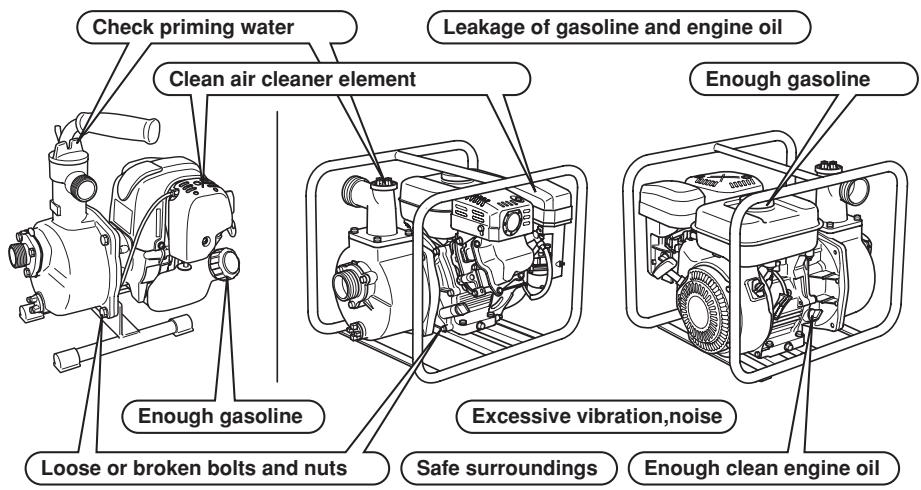
■ Carefully check fuel hoses and joints for looseness and fuel leakage. Leaked fuel creates a potentially dangerous situation.
- Check bolts and nuts for looseness. A loose bolt or nut may cause serious engine trouble.
■ Check the engine oil and refill if necessary.
- Check the fuel level and refill if necessary. Take care not to overfill the tank.
- Keep cylinder fins and recoil starter free of dirt, grass and other debris.
■ Wear snug fitting working clothes when operating the engine. Loose aprons, towels, belt, etc., may be caught in the engine or drive train, causing a dangerous situation.
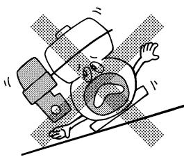
natural_image
Cartoon illustration of a person falling off a slope with a distressed face (no text or symbols)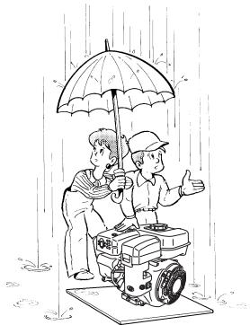
natural_image
Illustration of two people under an umbrella in the rain, one standing on a platform with a robot, the other gesturing with hand (no text or symbols present)
natural_image
Cartoon illustration of a smiling robot holding a wrench, no text or symbols presentEW120R

natural_image
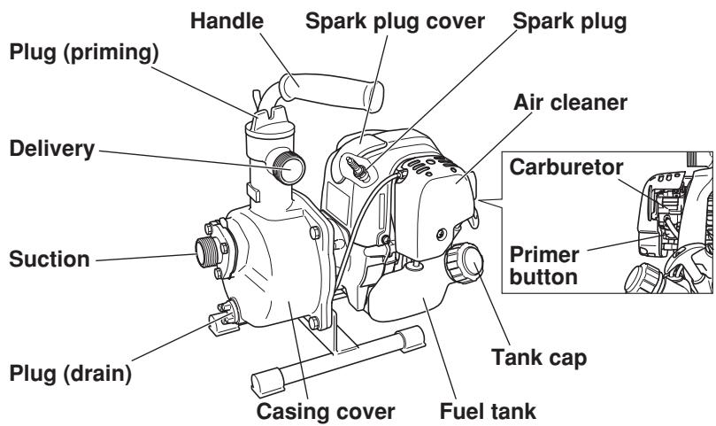
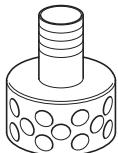
Technical line drawing of a cylindrical mechanical component with a central cylindrical shaft and textured base (no text or symbols)Strainer
natural_image
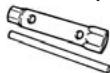
Two identical line drawings of a mechanical component with flanged ends and ridged top surfaces (no text or symbols)Hose coupling
Hose band

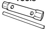
Tools
Instruction for use (This publication)

EW220R
EW320TR
Strainer
Instruction for use (This publication)

Hose coupling


Hose band
Tools

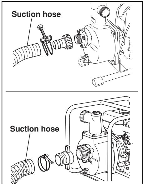
3. PREPARATIONS FOR STARTING
CONNECT SUCTION HOSE
Use a reinforced-wall or wire braided hose to prevent suction collapse.
Since the pump's self-priming time is directly proportional to hose length, a short hose is recommended.

CAUTION
Always use a strainer with the suction hose. Gravel or debris sucked into the pump will cause serious damage to the impeller and the pump casting.
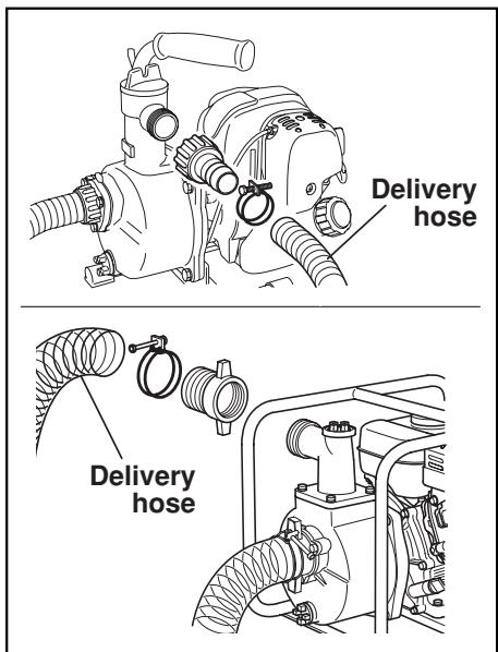
CONNECT DELIVERY HOSE
When using a fabric hose, always use a hose band to prevent the hose from disconnecting under high pressure.
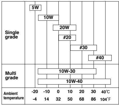
CHECK ENGINE OIL
Before checking or refilling engine oil, be sure the engine is located on stable, level surface and stopped.
■ Do not screw the oil gauge into the oil filler neck to check oil level. If the oil level is low, refill to the upper level with the following recommended oil.
■ Use 4-stroke automotive detergent oil of API service class SE or higher grade (SG, SH or SJ is recommended).
■ Select the viscosity based on the air temperature at the time of operation as shown in the table.
| Oil capacity | |
| EW120R | 2.7 oz (0.08 L) |
| EW220R | 20.3 oz (0.6 L) |
| EW320TR | 33.8 oz (1.0 L) |
bar
| Grade Type | Temperature Range | Wind Speeds | |---|---|---| | Single grade | -20 to -4 | 5W | | Single grade | -10 to 0 | 10W | | Single grade | 0 to 10 | 20W | | Single grade | 10 to 20 | #20 | | Single grade | 20 to 30 | #30 | | Single grade | 30 to 40 | #40 | | Multi grade | -4 to 104 °F | 10W-30 | | Multi grade | -4 to 104 °F | 10W-40 | Ambient temperature: -20 to -4, -10 to 0, 0 to 10, 20 to 30, 30 to 40°C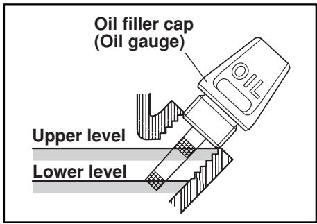
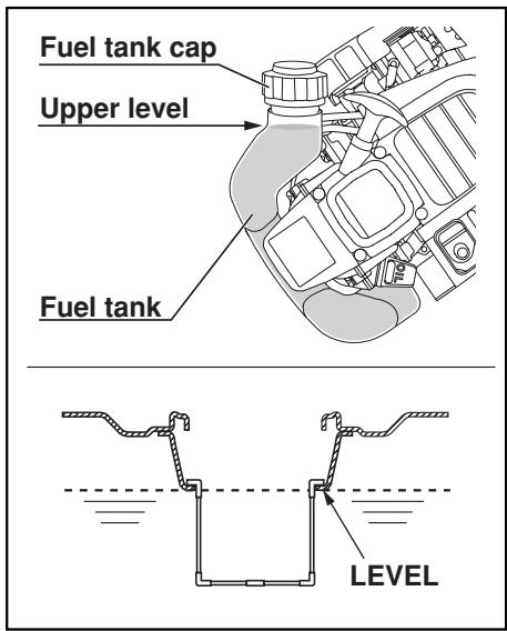
CHECK FUEL

WARNING
Do not refuel while smoking or near open flame or other such potential fire hazards. Otherwise fire accident may occur.
■ Stop the engine and open the cap.
■ Use automotive unleaded gasoline only. This engine is certified to operate on automotive unleaded gasoline.
| Fuel Tank Capacity | |
| EW120R | 0.13 U.S.gal (0.5L) |
| EW220R | 0.7 U.S.gal (2.7L) |
| EW320TR | 1.6 U.S.gal (6.1L) |
■ Incline the engine as fuel inlet upward, then refill fuel to the upper level. Do not fill fuel too much. (EW120R)
■ Close the fuel cock before filling the fuel tank. (EW220R, EW320TR)
■ Do not fill above the top of the fuel filter screen (marked LEVEL), or the fuel may overflow when it heats up later and expands. (EW220R, EW320TR)
■ When filling the fuel tank, always use the fuel filter screen.
■ Wipe off any spilled fuel before starting the engine.
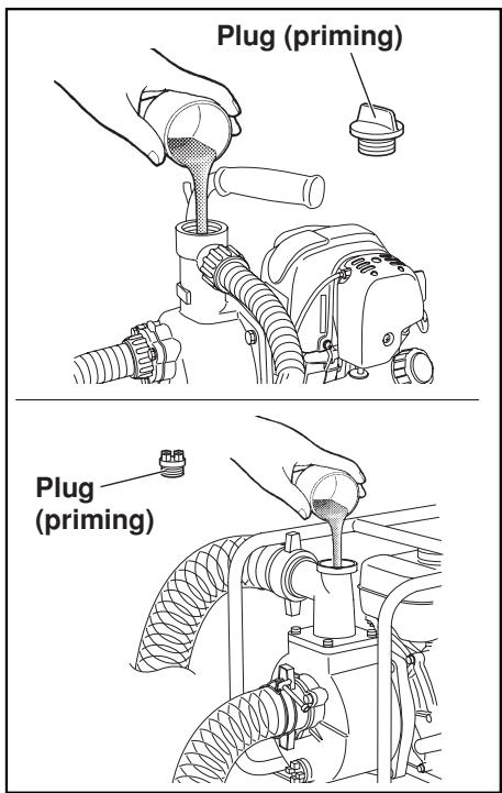
CHECK PRIMING WATER
It is recommended that the water chamber of pump casing should be primed with full of water before operating.

WARNING
Never attempt to operate the pump without priming water or the pump will overheat. Extended dry operation will destroy the mechanical seal. If the unit has been operated dry, stop the engine immediately and allow the pump to cool before adding priming water.
1. STARTING
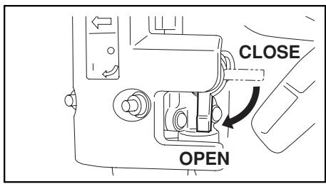
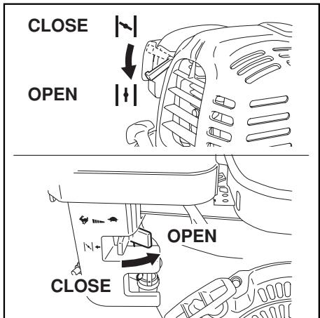
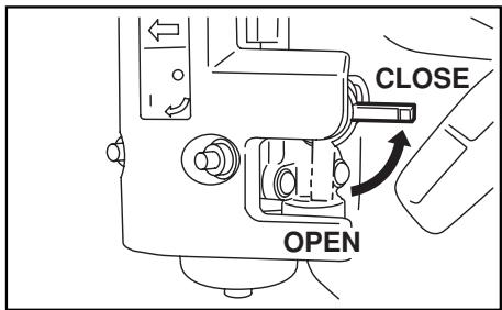
(a) Open the fuel cock. (EW220R, EW320TR)
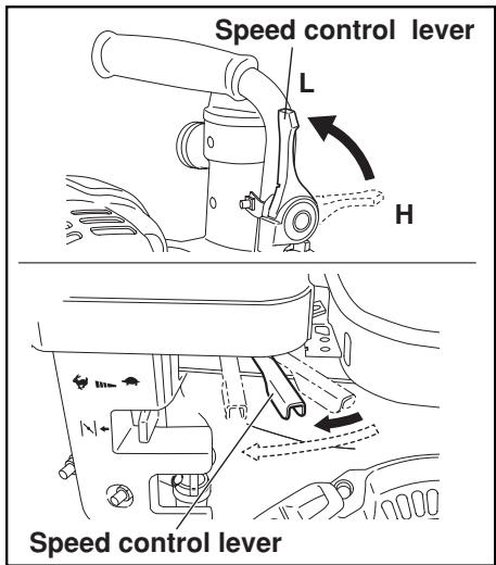
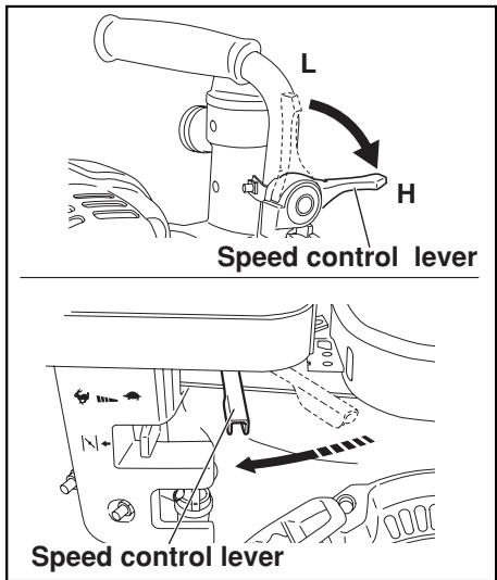
(b) Set the speed control lever to the idling position (L). (EW120R)
Set the speed control lever 1/3 of the way towards the high speed position. (EW220R, EW320TR)
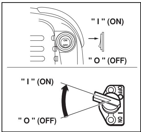
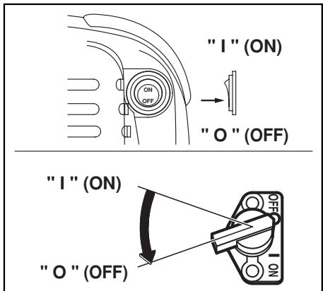
(c) Turn the STOP SWITCH to the position “ I ” (ON).
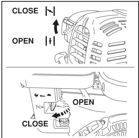
■ If the engine is cold, or the ambient temperature is low, close the choke lever fully.
■ If the engine is warm or the ambient temperature is high, close the choke half-way, or keep it fully open.
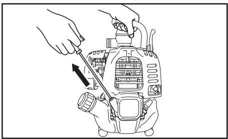
(e) Pull the starter handle slowly until resistance is felt. This is the “compression” point. Return the handle to its original position and pull swiftly.
Do not pull out the rope all the way. After starting the engine, allow the starter handle to return to its original position while still holding the handle.

natural_image
Line drawing of a hand using a screwdriver to adjust or install a mechanical device (no text or symbols present)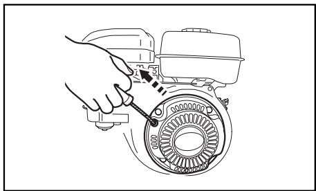
natural_image
Line drawing of a hand using a tool to adjust or install a mechanical component, no text or symbols present(f) After starting the engine, gradually open choke by turning the choke lever and finally keep it fully opened. Do not fully open the choke lever immediately when the engine is cold or the ambient temperature is low, because the engine may stop.
2. RUNNING
(a) After the engine starts, set the speed control lever at the low speed position (L) and warm it up without load for a few minutes.

(b) Gradually move the speed control lever toward the high speed position (H) and set it at the required engine speed.
■ Whenever high speed operation is not required, slow the engine down (idle) by moving the speed control lever to save fuel and extend engine life.
3. STOPPING
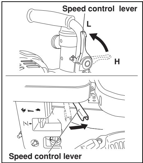
(a) Set the speed control lever at the low speed position and allow the engine to run at low speed for 2 or 3 minutes before stopping. (EW120R)
Set the speed control lever at the low speed position and allow the engine to run at low speed for 1 or 2 minutes before stopping. (EW220R, EW320TR)
(b) Turn the STOP SWITCH to the position "O" (OFF).
■ Do not stop the engine suddenly when it is running at high speed.
(c) Close the fuel cock. (EW220R, EW320TR)
(d) Pull the starter handle slowly and return the handle to its original position when resistance is felt. This operation is necessary to prevent outside moist air from intruding into the combustion chamber.
natural_image
Line drawing of a hand using a screwdriver to adjust or install a mechanical device (no text or symbols present)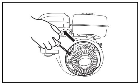
natural_image
Line drawing of a hand using a tool to adjust or install a mechanical component, no text or symbols present※STOPPING ENGINE WITH THE FUEL COCK (EW220R, EW320TR)
Close the fuel cock and wait for a while until the engine stops.
Avoid to let the fuel remain in the carburator over long periods, or the passages of the carburator may become clogged with impurities, and malfunctions may result.
5. MAINTENANCE SCHEDULE
MAINTENANCE, REPLACEMENT OR REPAIR OF THE EMISSION CONTROL DEVICES AND SYSTEMS MAY BE PERFORMED BY ANY NONROAD ENGINE REPAIR ESTABLISHMENT OR INDIVIDUAL.
DAILY INSPECTION
Before running the engine pump, check the following service items:
PERIODIC MAINTENANCE
Periodic maintenance is vital to safe and efficient operation of your engine pump. Check the table below for periodic maintenance intervals.
IT IS ALSO NECESSARY FOR THE USER OF THIS ENGINE PUMP TO CONDUCT THE MAINTENANCE AND ADJUSTMENTS ON THE EMISSION-RELATED PARTS LISTED BELOW TO KEEP THE EMISSION CONTROL SYSTEM EFFECTIVE.
The emission control system consists of the following parts:
(1) Carburetor and internal parts
(2) Cold start enrichment system, if applicable
(3) Intake manifold, if applicable
(4) Air cleaner elements
(5) Spark plug
(6) Magneto or electronic ignition system
(7) Spark advance/retard system, if applicable
(8) Exhaust manifold, if applicable
(9) Hoses, belts, connectors, and assemblies
The maintenance schedule indicated in the following table is based on the normal engine operation. Should the engine be operated in extremely dusty condition or in heavier loading condition, the maintenance intervals must be shortened depending on the contamination of oil, clogging of filter elements, wear of parts, and so on.
Periodic Maintenance Schedule table
| Maintenance Items | Every 8 hours (Daily) | Every 20 hours | Every 50 hours (Weekly) | Every 200 hours (Monthly) | Every 500 hours | Every 1000 hours |
| CLEAN PUMP SET AND CHECK BOLT AND NUTS | ●(Daily) | |||||
| CHECK AND REFILL ENGINE OIL | ● (Refill daily up to upper level) | |||||
| CHANGE ENGINE OIL (*Note1) | ●(Initial) | ● (Every 100 hours) | ||||
| CLEAN SPARK PLUG | ● | |||||
| CLEAN AIR CLEANER | ● | |||||
| REPLACE AIR CLEANER ELEMENT | ● | |||||
| CLEAN FUEL STRAINER | ● | |||||
| CLEAN AND ADJUST SPARK PLUG AND ELECTRODES | ● | |||||
| REPLACE SPARK PLUG | ● | |||||
| SPARK ARRESTER (OPTIONAL PART) | ● (Every 100 hours) | |||||
| REMOVE CARBON FROM CYLINDER HEAD (*Note 2) | ● | |||||
| CHECK AND ADJUST VALVE CLEARANCE, (*Note 2) | ● | |||||
| CLEAN AND ADJUST CARBURETOR (*Note 2) | ● | |||||
| REPLACE FUEL LINES | ●(Yearly) | |||||
| OVERHAUL ENGINE (*Note 2) | ● | |||||
*NOTE: 1. Initial oil change should be performed after first twenty (20) hours of operation. Thereafter change oil every hundred (100) hours. Before changing oil, check for a suitable way to dispose of old oil. Do not pour it down into sewage drains, onto garden soil or into open streams. Your local zoning or environmental regulations will give you more detailed instructions on proper disposal.
*NOTE: 2. As to the procedures for these items, please refer to the SERVICE MANUAL or consult your nearest Makita service dealer.
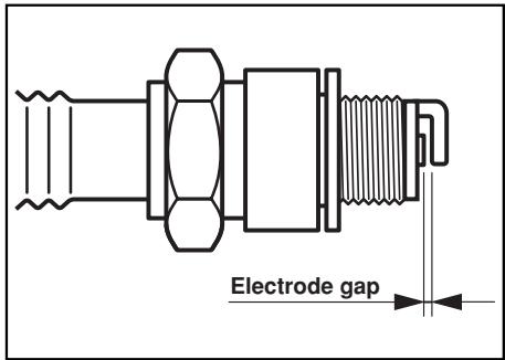
INSPECTING THE SPARK PLUG
■ Clean off carbon deposits on the plug electrode using a plug cleaner or wire brush.
■ Check electrode gap.
Adjust the gap, if necessary, by carefully bending the side electrode.
■ Use a proper spark plug
| Model | Type | Electrode gap |
| EW120R | NGK CMR6A | 0.03 in.(0.7 to 0.8 mm) |
| EW220REW320TR | NGK BR-6HS(CHAMPION RL86C) | 0.02 to 0.03 in.(0.6 to 0.7 mm) |
ENGINE OIL CHANGE
Initial oil change : After 20 hours of operation
Thereafter : Every 100 hours of operation
(a) When changing oil, stop the engine and loosen the drain plug. Drain the used oil while the engine is warm. Warm oil drains quickly and completely.

CAUTION
To prevent injury, pay attention to the hot oil. Make sure the fuel cap is tightly secured to avoid spillage.
(b) Re-install the drain plug before refilling oil.
| Oil capacity | |
| EW120R | 2.7 oz (0.08 L) |
| EW220R | 20.3 oz (0.6 L) |
| EW320TR | 33.8 oz (1.0 L) |

natural_image
Illustration of two mechanical tools: one using a tool to press or install a block, the other handling a tool with a handle (no text or symbols present)(c) Refer to page 7 for the recommended oil.
■ Always use the best grade and clean oil. Contaminated oil, poor quality oil and shortage of oil cause damage to engine or shorten the engine life.
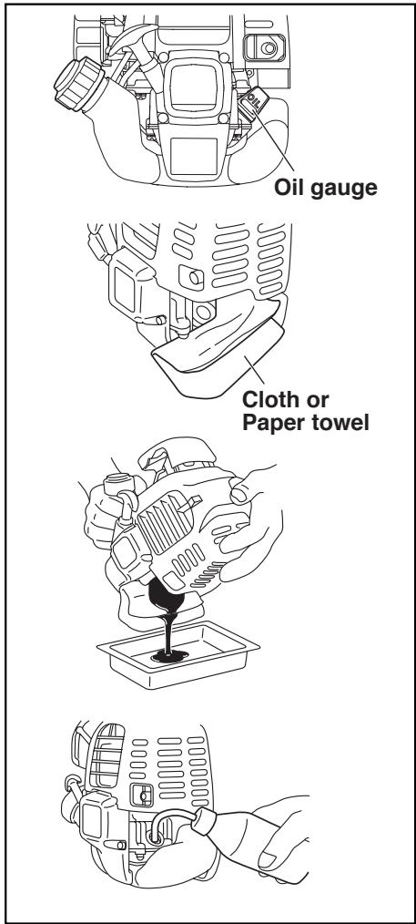
(d) Procedures for EW120R
1) Remove the oil gauge. Be cautious to place the oil gauge in a place where it will not gather dirt, dust or other foreign matter.
2) Place a cloth or paper towel to the area around the oil filler hole.
3) Remove the oil gauge, then tilt the engine and drain the oil into a pan or other receptacle.
4) Put the engine on a level surface, then fill with the oil up to the point of overflowing the filler neck. Pour the oil in from a squeeze bottle or other appropriate.
5) After filling the engine with oil, reinsert the oil gauge.
Ensure that the oil gauge is tight, as if it loosens later oil will leak out.
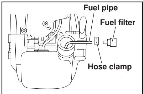
CLEANING FUEL FILTER (EW120R)
(a) Remove the hose clamp and pull out the fuel filter from fuel pipe.
(b) Wash the fuel filter with kerosene.
(c) After washing, reassemble it. If the fuel filter is heavy dirty, replace it with new one.
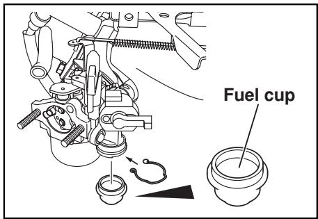
CLEANING FUEL CUP (EW220R, EW320TR)
(a) Inspect fuel cup for water and dirt.
(b) To remove water and dirt, close the fuel cock and remove the fuel cup.
(c) After removing dirt and water, wash the fuel cup with kerosene or gasoline. Reinstall securely to prevent leakage.
ADJUSTING IDLING RPM (CARBURETOR) (EW120R)
When adjust screw is turned right, engine rpm increases, and when it is turned left, rpm decreases.
| Normal idling rpm | 3000±100rpm |
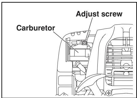
NOTE:
The carburetor greatly affects the performance of the engine.
Since it has been adjusted carefully at our factory before shipment, avoid adjusting unless absolutely necessary.
If adjustments are needed, contact your nearest dealer.
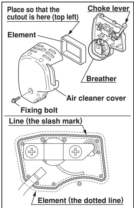
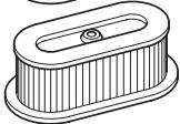
CLEANING AIR CLEANER
A dirty air cleaner element will cause starting difficulty, power loss, engine malfunctions, and shorten engine life extremely. Always keep the air cleaner element clean.
EW120R
■ Remove the fixing bolt of air cleaner cover.
■ Pull out the lower edge of the cover to remove the air cleaner cover.
■ Place the choke lever to the fully closed position, taking care to ensure that dust and dirt are not allowed to enter the carburetor.
■ Remove the element, then clean it with a solution of warm water and a mild detergent, thoroughly drying it afterward. Install it in alignment with the lines as shown in illustration.
■ Wipe off any oil adhering to the area around the air cleaner cover and breather with a cloth.
■ After cleaning, reassemble the clean-er cover (insert the tab at the top first, then insert the bottom tab) and tighten the fixing bolt.
EW220R, EW320TR
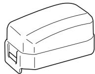
(a) Urethane Foam Element Type
■ Remove the element and wash it in kerosene or diesel fuel. Then saturate it in a mixture of 3 parts kerosene or diesel fuel and 1 part engine oil. Squeeze the element to remove the mixture and install it in the air cleaner.
(b) Urethane Foam Dual Element Type
■ Urethane Foam cleaning
Wash and clean the urethane foam with detergent. After cleaning, dry it. Clean the urethane foam element every 50 hours.
■ Second element
Clean by tapping gently to remove dirt and blow off dust. Never use oil. Clean the paper element every 50 hours of operation, and replace element set every 200 hours.
natural_image
Line drawing of a rectangular electronic component with a small protrusion (no text or symbols)
Urethane Foam Element
natural_image
Line drawing of a rectangular device with a handle and two small accessories (no text or symbols)
Urethane Foam Element
Paper Element
NOTE:
Clean and replace air cleaner elements more often when operating in dusty environments.
Replace the element in case that dirt or dust can not be removed and/or that the element is deformed or deteriorated.
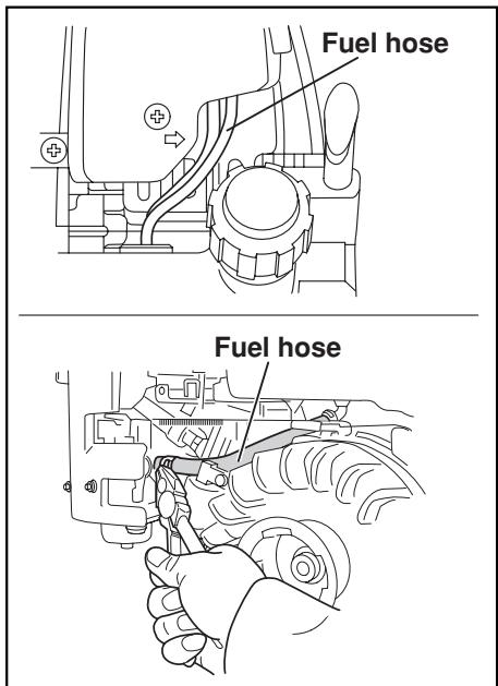
FUEL HOSE REPLACEMENT

WARNING
Take extreme caution when replacing fuel hose ; gasoline is flammable.
Replace the fuel hose every 1,000 hours or every year.
If the fuel hose leak is found, replace the fuel hose immediately.
CHECKING BOLTS, NUTS AND SCREWS
Retighten loose bolts and nuts.
Check for fuel and oil leaks.
Replace damaged parts with new ones.
Turn the knob counterclockwise and open the casing cover holder.
Pull the casing toward you, and then remove the casing and the inner casing.
Clean the inside of pump casing and casing cover with clean water.
7. PREPARATIONS FOR STORAGE
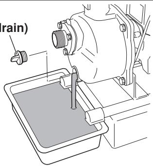
1. WATER
Drain all water from the drain plug.

CAUTION
When retightening drain plug, be sure to clean the drain plug and the thread of casing. Otherwise, the thread may be damaged.
Plug (drain)
Plug (drain)
natural_image
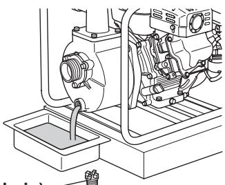
Technical line drawing of a mechanical pump assembly with internal components and a base (no text or symbols)2. DISCONNECT THE DELIVERY HOSE
Tilt the pump and drain all water from delivery hole. Severe damage to pump may result if water freezes in the pumping chamber.
3. DISCHARGE FUEL

WARNING
: Flame Prohibited
If you do not use the engine more than 1 month, discharge fuel to prevent gum in the fuel system and carburetor parts.
EW120R
■ Pour out the fuel in the tank from its filler neck.
■ Push the primer pump of the carburetor until the fuel in it is thoroughly discharged.
EW220R, EW320TR
■ Remove the strainer cup, place the strainer over a container and open the strainer cock to discharge fuel from the fuel tank.
■ Remove the drain screw of the carburetor float chamber and discharge fuel.
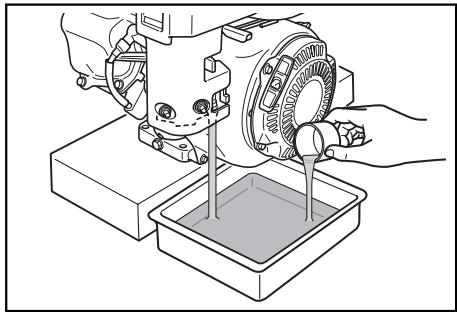
natural_image
Illustration of a mechanical device pouring liquid into a container (no text or symbols)4. ENGINE OIL
■ Change the engine oil with fresh oil.
■ Remove the spark plug, pour about 5 cc of engine oil into the cylinder, slowly pull the starter handle of the recoil starter 2 or 3 times, and reinstall the spark plug.
natural_image
Illustration of two people interacting near a container, one making a peace sign (no text or symbols present)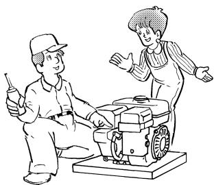
natural_image
Illustration of two workers operating a small machine, one holding a tool and the other gesturing with open hands (no text or symbols present)5. CLEAN AND STORE
■ Slowly pull the recoil starter handle until resistance is felt and leave it in that position.
■ Clean the pump thoroughly with an oiled cloth, put the cover on, and store the pump indoors in a well ventilated, low humidity area.
8. OIL SENSOR (OPTIONAL)
1. FUNCTION OF OIL SENSOR (EW220R, EW320TR)
The engine will stop automatically when the oil level falls below the safety limit.
The engine cannot be started unless the level is raised above the prescribed limit.
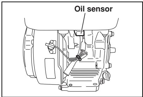
2. RESTARTING
(a) Fill the crankcase with oil up to the proper level.
(b) As for restarting and operating the engine, refer to section "4. OPERATION" on page 10.
■ Check the wire connector from the engine. It must be connected securely to the wire from oil sensor.
■ When selecting the engine oil, refer to page 7 for the recommended oil.
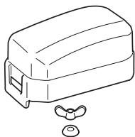
9. SPARK ARRESTER (OPTIONAL)
SPARK ARRESTER
In a dry or wooded area, it is recommendable to use the product. with a spark arrester. Some areas require the use of a spark arrester. Please check your local laws and regulations before operating your product.
The spark arrester must be cleaned regularly to keep it functioning as designed. A clogged spark arrester :
● Prevents the flow of exhaust gas
- Reduces engine output
● Increases fuel consumption
● Makes starting difficult
If the engine has been running, the muffler and the spark arrester will be very hot. Allow the muffler to cool before cleaning the spark arrester.
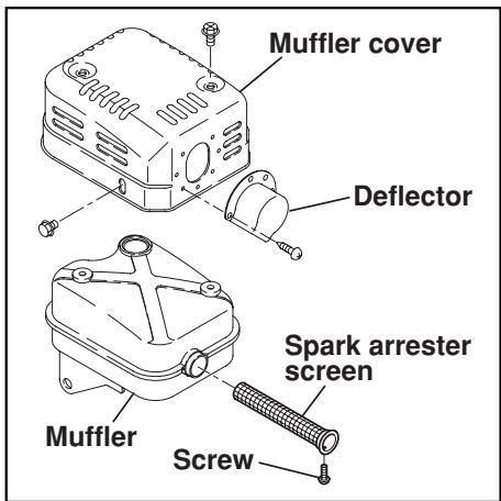

How to remove the spark arrester
- Remove the flange bolts from the muffler cover and remove the muffler cover.
- Remove the special screw from the spark arrester and remove the spark arrester from the muffler.
Clean the spark arrester screen
Use a brush to remove carbon deposits from the spark arrester screen. Be careful to avoid damaging the screen.
The spark arrester must be free of breaks and holes. Replace the spark arrester if it is damaged.
Install the spark arrester, and muffler protector in the reverse order of disassembly.
10. TROUBLESHOOTING
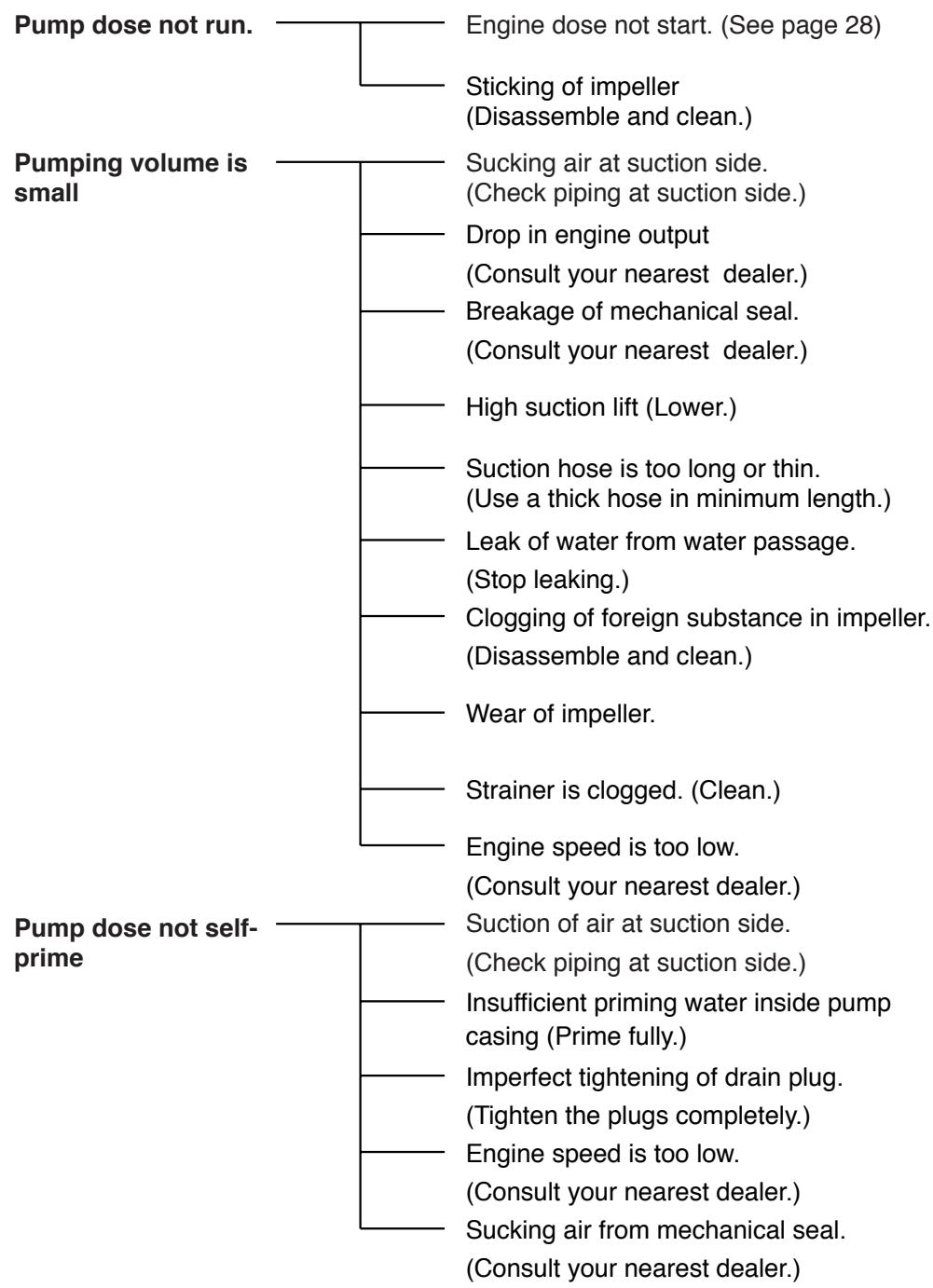
flowchart
graph TD
    A["Pump dose not run."] --> B["Engine dose not start. (See page 28)"]
    A --> C["Sticking of impeller (Disassemble and clean)."]
    D["Pumping volume is small"] --> E["Sucking air at suction side. (Check piping at suction side.)"]
    D --> F["Drop in engine output (Consult your nearest dealer.)"]
    D --> G["Breakage of mechanical seal. (Consult your nearest dealer.)"]
    D --> H["High suction lift (Lower.)"]
    D --> I["Suction hose is too long or thin. (Use a thick hose in minimum length.)"]
    D --> J["Leak of water from water passage. (Stop leaking.)"]
    D --> K["Clogging of foreign substance in impeller. (Disassemble and clean.)"]
    D --> L["Wear of impeller."]
    D --> M["Strainer is clogged. (Clean.)"]
    D --> N["Engine speed is too low. (Consult your nearest dealer.)"]
    O["Pump dose not self-prime"] --> P["Suction of air at suction side. (Check piping at suction side.)"]
    O --> Q["Insufficient priming water inside pump casing (Prime fully.)"]
    O --> R["Imperfect tightening of drain plug. (Tighten the plugs completely.)"]
    O --> S["Engine speed is too low. (Consult your nearest dealer.)"]
    O --> T["Sucking air from mechanical seal. (Consult your nearest dealer.)"]
WHEN ENGINE DOES NOT START :
■ Perform the following checks before you take the pump to your Makita dealer.
■ If you still have trouble after completing the checks, take the pump to your nearest Makita dealer.

WARNING
Before testing, carefully wipe off spilled fuel.
Put the plug as far away from the spark plug hole as possible. Ground the side of the electrode to any engine ground.
flowchart
graph TD
    A["Starting failure"] --> B["Is there a strong spark across the electrode?"]
    A --> C["Is there enough compression?"]
    A --> D["Is the spark plug wet with fuel?"]

    B --> E["1. Remove the plug and connect it to the plug cap.<br>Pull the starter handle while putting the plug against the engine ground."]
    B --> F["2. Try with a new plug if the spark is week or no spark files."]
    B --> G["3. The ignition system is faulty if there is no spark with a new plug.<br>Take your pump to your nearest Makita dealer."]

    C --> H["1. Pull the starter handle slowly and check if resistance is felt."]
    C --> I["2. If little force is required to put the starter handle check if the spark plug is tightened firmly."]
    C --> J["3. If the spark plug is loose, tighten it."]
    C --> K["4. If compression is still low, consult your nearest dealer."]

    D --> L["1. Choke (close choke lever) and pull the starter handle five or six times.<br>Remove the plug and check if its electrode is wet. If the electrode is wet, fuel is well supplied to your engine."]
    D --> M["2. When the electrode is dry, check when the fuel stops. (Check the fuel intake of the carburetor and fuel strainer intake.)"]
    D --> N["3. In case the engine dose not start with well supplied fuel, try using different fuel."]
| Model | EW120R | EW220R | EW320TR | ||
| PUMP | Type | Self-Priming, Centrifugal pump | Self-Priming, Trash pump | ||
| Suction x DeliveryDiameters | in. (mm) | 1 x 1 in.(25.4 x 25.4 mm) | 2 x 2 in.(50.8 x 50.8 mm) | 3 x 3 in.(76.2 x 76.2 mm) | |
| Total Head | ft (m) | 115 (35) | 105 (32) | 92 (28) | |
| Maximum DeliveryVolume | U.S.gal/min(L / min) | 34(130) | 137(520) | 343(1300) | |
| Suction Head | ft (m) | 26 (8) | |||
| Axle Seal Material(Mechanical Seal) | Ceramic-carbon | Silicon-carbide | |||
| ENGINE | Model | EH025 | EX13 | EX27 | |
| Type | Air-Cooled,4-Stroke, OHV,Gasoline Engine | Air-Cooled,4-Stroke, OHC,Gasoline Engine | |||
| Lubricant | Automotive detergent oil (API / SE or higher grade,SG, SH or SJ is recommended. SEA / 10W-30 etc.) | ||||
| Oil Capacity | oz. (liter) | 2.7(0.08) | 20.3(0.6) | 33.8(1.0) | |
| Fuel | Automotive unleaded gasoline | ||||
| Fuel Tank Capacity | U.S.gal (liter) | 0.13 (0.5) | 0.7 (2.7) | 1.6 (6.1) | |
| Spark Plug | NGK CMR6A | NGK BR-6HS (CHAMPION RL86C) | |||
| Starting System | Recoil starter | ||||
| Dimensions | Length | in. (mm) | 13.0 (331) | 18.5 (470) | 26.5 (672) |
| Width | in. (mm) | 8.4 (213) | 13.5 (344) | 19.1 (484) | |
| Hight | in. (mm) | 13.6 (345) | 16.3 (414) | 24.0 (610) | |
| Dry Weight | lb. (kg) | 12.8 (5.8) | 54.9 (24.9) | 106.9 (48.5) | |
| Standard Accessories | Engine tool kit (1 set), Strainer (1 pc),Hose coupling (2 pcs.), Hose band (3 pcs.) | ||||
| Valve Clearance(Intake and Exhaust) | 0.0039 ± 0.0008 in. ( 0.1 ± 0.03 mm)Note: Adjust the valve clearance while the engine is cold. | ||||
| Emissions Durability Period(California only) | hours | 125 | 500 | ||
Makita Corporation
3-11-8, Sumiyoshi-cho
Anjo, Aichi 446-8502 Japan


- INSTRUCTIONS FOR USE
- MANUEL D'UTILISATION
- !
- WARNING:
- NOTICE
- AIR INDEX
- FEDERAL EMISSIONS COMPONENT DEFECT WARRANTY
- EMISSION COMPONENT DEFECT WARRANTY PERIOD
- PARTS COVERED
- OBTAINING WARRANTY SERVICE
- WHAT IS NOT COVERED
- OWNER'S WARRANTY RESPONSIBILITIES
- THINGS YOU SHOULD KNOW ABOUT THE EMISSION CONTROL SYSTEM WARRANTY MAINTENANCE AND REPAIRS
- HOW TO MAKE A CLAIM
- ARIZONA
- CALIFORNIA
- COLORADO
- FLORIDA
- GEORGIA
- ILLINOIS
- MARYLAND
- MASSACHUSETTS
- MINNESOTA
- MISSOURI
- NEBRASKA
- NEVADA
- NEW JERSEY
- NEW YORK
- OREGON
- PENNSYLVANIA
- PUERTO RICO
- TENNESSEE
- TEXAS
- WISCONSIN
- CALIFORNIA EMISSION CONTROL WARRANTY STATEMENT (This warranty does not apply in any other state.) YOUR WARRANTY RIGHTS AND OBLIGATIONS
- MANUFACTURER'S WARRANTY COVERAGE :
- OWNER'S WARRANTY RESPONSIBILITIES :
- LIMITED WARRANTY on Emission Control Systems – California Only –
- WARRANTY PERIOD
- WHAT IS COVERED UNDER THIS WARRANTY
- EMISSION-RELATED PARTS COVERED UNDER THIS WARRANTY
- WHAT IS NOT COVERED UNDER THIS WARRANTY
- MAINTENANCE SCHEDULE
- PROCEDURE
- INTERVAL
- REPAIR AND REPLACEMENT OF EMISSION-RELATED PARTS
- HOW TO FILE A WARRANTY CLAIM AND WHERE TO GET WARRANTY SERVICES
- FACTORY SERVICE CENTERS IN CANADA
- BRITISH COLUMBIA
- ALBERTA
- 8-6115 Fourth Street S.E., Calgary, T2H.2H9
- SASKATCHEWAN
- MANITOBA
- ONTARIO
- QUÉBEC
- FOREWORD
- CONTENTS
- WARNING
- CAUTION
- : EXHAUST PRECAUTIONS
- : FIRE PREVENTION
- WARNING : OTHER SAFETY PRECAUTIONS
- NOTE
- CAUTION : PRE-OPERATION CHECKS
- EW120R
- EW220R
- EW320TR
- PREPARATIONS FOR STARTING
- CONNECT SUCTION HOSE
- CONNECT DELIVERY HOSE
- CHECK ENGINE OIL
- CHECK FUEL
- CHECK PRIMING WATER
- STARTING
- RUNNING
- STOPPING
- ※STOPPING ENGINE WITH THE FUEL COCK (EW220R, EW320TR)
- MAINTENANCE SCHEDULE
- DAILY INSPECTION
- PERIODIC MAINTENANCE
- INSPECTING THE SPARK PLUG
- ENGINE OIL CHANGE
- CLEANING FUEL FILTER (EW120R)
- CLEANING FUEL CUP (EW220R, EW320TR)
- ADJUSTING IDLING RPM (CARBURETOR) (EW120R)
- NOTE:
- CLEANING AIR CLEANER
- EW220R, EW320TR
- FUEL HOSE REPLACEMENT
- CHECKING BOLTS, NUTS AND SCREWS
- PREPARATIONS FOR STORAGE
- WATER
- DISCONNECT THE DELIVERY HOSE
- DISCHARGE FUEL
- : Flame Prohibited
- ENGINE OIL
- CLEAN AND STORE
- OIL SENSOR (OPTIONAL)
- FUNCTION OF OIL SENSOR (EW220R, EW320TR)
- RESTARTING
- SPARK ARRESTER (OPTIONAL)
- SPARK ARRESTER
- How to remove the spark arrester
- Clean the spark arrester screen
- TROUBLESHOOTING
- WHEN ENGINE DOES NOT START :
- Makita Corporation
Brand : MAKITA
Model : EW220R
Category : Water pump