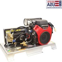
TM2810241E - Pressure washer Simpson - Free user manual and instructions
Find the device manual for free TM2810241E Simpson in PDF.


| Product type | High pressure cleaner |
| Brand | Simpson |
| Model | TM2810241E |
| Dimensions (L x W x H) | 52 x 40 x 90 cm |
| Net weight | 25 kg |
| Power supply | 230 V ~ 50 Hz |
| Rated power | 2800 W |
| Maximum pressure | 180 bar |
| Maximum water flow | 600 L/h |
| Maximum water temperature | 60 °C |
| High pressure hose length | 15 m |
| Motor type | Induction electric motor |
| Main functions | High pressure washing, rinsing, detergent application |
| Included accessories | Gun with adjustable nozzle, lance, rotary nozzle, garden hose |
| Maintenance and cleaning | Rinse system after use, check filters regularly |
| Safety | Automatic shut-off, overload protection, safety valve |
| Spare parts and repairability | Available via Simpson after-sales service; repairability index: 7/10 |
| General information | Domestic and light professional use, 2-year warranty |
Frequently Asked Questions - TM2810241E Simpson
User questions about TM2810241E Simpson
0 question about this device. Answer the ones you know or ask your own.
Ask a new question about this device
Download the instructions for your Pressure washer in PDF format for free! Find your manual TM2810241E - Simpson and take your electronic device back in hand. On this page are published all the documents necessary for the use of your device. TM2810241E by Simpson.
USER MANUAL TM2810241E Simpson
natural_image
Technical line drawing of a mechanical device with no visible text or symbols
natural_image
Technical line drawings of two industrial machines with internal components and mounting brackets (no text or symbols)
LOOK BEFORE YOU PUMP!

READ THIS MANUAL CAREFULLY BEFORE OPERATION
Failure to follow the instructions and safety precautions in this manual can result in property damage, serious injury and/or death.
If your pressure washer is not working or if there are parts missing or broken, please DO NOT RETURN IT TO THE PLACE OF PURCHASE. Contact our Customer Service Department by calling 1-833-362-7368 or emailing cservice@fna-group.com
SAVE THIS MANUAL FOR FUTURE REFERENCE
NOTE: Photographs and line drawings used in this manual are for reference only and may not represent your specific model.
THIS PAGE WAS INTENTIONALLY LEFT BLANK
SAVE THIS MANUAL FOR FUTURE USE
Keep this manual for future reference. This manual should be considered a permanent part of the product and stay with it. This manual should be available to anyone operating the product(s) it covers. This manual should remain with the product(s) it covers if sold to a new owner. If the manual becomes damaged, lost, or otherwise unusable, contact customer support by calling 1-833-362-7368 or emailing cservice@fna-group.com
Write down the model number, serial number, and purchase date of this product in the spaces provided below then keep this manual with the purchase receipt(s) for future reference.
Model Number:
Serial Number:
Purchase Date:

CALIFORNIA PROPOSITION 65 WARNING
This product and the engine exhaust can expose you to chemicals which are known to the state of California to cause cancer, birth defects, or other reproductive harm. For more information on California Proposition 65, go to www.P65Warnings.ca.gov.

POLYCYCLIC AROMATIC HYDROCARBON WARNING
The air filter element and air box assembly may contain polycyclic aromatic hydrocarbons (PAHs). Some PAHs may cause cancer. To avoid exposure to PAHs, wear gloves when performing air filter maintenance.
SAFETY INSTRUCTIONS | 4
Read this Manual Before Operating 4
Additional Instructions 4
Hazard Alert Symbols 4
DISCLAIMERS | 6
PERSONAL PROTECTIVE EQUIPMENT | 6
UNPACKING | 6
ASSEMBLY | 7
Adding the Foot Kit | 7
Connecting to Battery Source 8
Connecting to Fuel Source 9
Storing the Nozzles | 9
Adding the Pump Breather Cap 9
COMPONENT LOCATION | 10
CONNECTING HOSES | 14
PURGING AIR FROM THE PUMP | 15
NOZZLES | 16
Nozzle Selection | 16
Nozzle Installation 16
OPERATING CHECKLIST | 17
Location | 17
High Altitude Operation (Non-EFI Models, Only) | 18
Operating Conditions 18
Checking the Engine Oil | 20
Checking Fuel | 22
STARTING THE ENGINE
SHUTTING OFF THE ENGINE
OPERATION TIPS
Terms
Preparation
Pressure Washing
Adjusting Surface Pressure
Adjusting Unloader Hand Control Knob to Adjust Pressure
TROUBLESHOOTING
MAINTENANCE
Maintenance
Cleaning the Pressure Washer
Connections
Nozzle Cleaning
Water Inlet Filter
Pump Maintenance
Pump Gearbox Maintenance
Belt Maintenance
Engine Maintenance
24
26
26
26
26
27
27
27
28
30
30
31
31
31
32
33
34
35
37
STORAGE AND TRANSPORTATION
Storing for Two Months or Less
Storing for More Than Two Months
Transportation
37
37
38
38
USING SIMPSON® PUMP GUARD
WARRANTY
39
40
READ THIS MANUAL BEFORE OPERATING
This manual contains important safety information and instructions. Do not operate this product until you have read, and completely understand all safety, operation, and maintenance instructions listed in this manual. Failure to follow the information contained in this manual will result in property damage, injury, and/or death.
NOTE: The warnings and precautions discussed in this manual cannot cover all conditions and situations that may occur. The operator must understand awareness and caution are factors which cannot be built into this product and so must be exercised by the operator.
ADDITIONAL INSTRUCTIONS
Along with this manual, be sure to read any additional instructions provided both on and with the product, attached equipment, accessories, and the engine powering the product. Pay careful attention to all additional safety rules and instructions on proper startup, operation, and shutdown procedures. Always use any recommended protective apparel that may be needed to operate the equipment safely.

HAZARD ALERT SYMBOLS
Be sure to understand the safety symbols and definitions listed below. Each symbol contains one of four words: DANGER, WARNING, CAUTION, NOTICE, indicating different levels of hazard severity. These symbols are used throughout this manual and are followed by information about a specific hazard, the consequences of the hazard, and instructions on how to avoid the hazard. Failure to heed these symbols and follow the instructions provided with them will result in property damage, injury, and/or death.

Indicates an imminently dangerous situation, which if not avoided, will result in property damage, serious injury, and/or death.
Indicates a potentially hazardous situation, which if not avoided, could result in property damage, serious injury, and/or death.

Indicates a hazardous situation, which if not avoided, could result in property damage and/or minor to moderate injury.

Indicates information considered important, but not directly hazard related.


UNSAFE PRACTICES
Do not operate the unit when fatigued or under the influence of drugs and/or alcohol. Stay alert at all times. Do not overreach or stand on an unstable surface. Do not use pressure washer while standing on a ladder. Reactive force of the spray will cause spray gun/wand to kickback and could cause the operator to slip or fall or misdirect the spray. Improper control of the spray gun/wand can result in injuries to self or others. Grip gun/wand firmly with both hands. Expect the gun to kickback when triggered. Never point wand at or spray people and/or animals.
CAUTION

Hoses may pose a tripping hazard that can cause injuries resulting from a fall.

SLIP / TRIP HAZARDS
When pressure washing in public areas, signs should be posted that indicate to stay clear of the area as high-pressure washing is being performed. Also, signs should be posted that the surface may be slippery and trip hazards may be present.
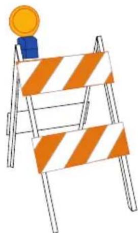
Special consideration needs to be made to the safety of not just the operator of the pressure washer, but also people who may be adjacent to the area being cleaned. The best way to warn unsuspecting individuals is with signage and barriers.
Barriers can be as simple as plastic traffic cones or barricades to using barrier belts around the area being cleaned. Remember, pressure washing can dislodge weak or broken pavement turning it into projectiles that may injure others. Keeping people clear of the area is the best way to avoid injury.
Wet pavement can be slippery to unsuspecting individuals causing injury from slips and falls. High-pressure and low-pressure hoses can be trip hazards. Segregating the area and placing appropriate signage can reduce injury.
Sign examples
CAUTION

CAUTION

KEEP OUT
HIGH PRESSURE WASHING IN PROGRESS

Barrier examples

natural_image
Illustration of a construction barrier with orange and white stripes, topped with a yellow coin (no text or symbols)
natural_image
Illustration of two orange traffic cones with white and black stripes, connected by a dashed orange bar (no text or symbols)NOTICE
This appliance is not intended to be used by persons with reduced physical, sensory, or mental capabilities, or lack of experience and knowledge, unless they have been given supervision or instruction concerning use of the appliance by a person responsible for their safety.
Children should be supervised to ensure that they do not use or play with the appliance.
DISCLAIMERS
- All information in this publication was based on the latest product information available at the time of printing. The FNA Group reserves the right to update, change, and/or improve the product and this document at any time, without notice, and without incurring any obligation.
- This manual may cover more than one machine. The pictures and figures in the manual should be used for reference only. There may be differences between your product and the pictures, drawings, and diagrams in this manual.
PERSONAL PROTECTIVE EQUIPMENT (PPE)
It is important to understand what personal protective equipment (PPE) should be utilized when using your pressure washer as light or unsecured objects can become hazardous projectiles. Below is a list of PPE items that should be utilized at all times when using the pressure washer.
Hearing - Ear plugs or muffs to protect your hearing.
Vision - ANSI-approved Z87.1 safety glasses or goggles to protect your eyes.
Clothing - Long pants and a long-sleeved shirt to protect your legs and arms from flying debris.
Shoes - Rubber-soled shoes that fully cover your feet to protect against debris, over spray, and electric shock.
UNPACKING
Follow the steps outlined in this section to unpack and assemble your pressure washer. If you have any questions regarding the unpacking or assembly of your pressure washer, please have your model number and serial number ready, then contact customer support at 1-833-362-7368 or email cservice@fna-group.com.
- Place the shipping pallet on a solid, flat surface.
- Carefully cut the shipping straps.
- Using a forklift, remove the unit from the shipping pallet.
Adding the Foot Kit
- Using a forklift, lift the unit to a comfortable working level.
- Place one flat washer (B) onto each bolt (A) then insert them through the mounting feet (C).
- From below, insert the mounting feet assembly from step #2.
- Place one flat washer (B) onto the bolt, then thread on a nylon insert hex nut (D); tighten.


IMPROPER ASSEMBLY
Ensure all parts are assembled in the order and orientation as directed in this manual. Failure to correctly assemble parts may lead to serious injuries and/or property damage.
Connecting to Battery Source (if applicable)


BATTERY CONNECTIONS
Always remove the black, negative (-) battery cable first and always connect the black, negative (-) battery cable last. Failure to do this could cause metallic tools to short to the frame possibly causing burns or the battery to explode.
A 12-volt battery (not included) may be required to start the engine. In order to connect a battery to the pressure washer engine, battery cables (not provided) will need to be connected to the engine starter and the pressure washer frame.
Note the following:
- Do not route the battery cables near any hot, moving, or rotating parts, or sharp edges.
- Route the battery cables away from other electrical wires or fuel lines.
- Protect the positive connection with a cover or insulation.
- Use cable grommets if the cables need to pass through metallic panels.
- The battery leads must be properly sized (gauge) for the cable length.
- For a twin-cylinder engine, use a battery with a minimum capacity of 45 AH (400 CCA). For a single-cylinder engine, use a battery with a minimum capacity of 24 AH (175 CCA).
Connect a RED positive battery lead (not provided) to the battery terminal (A) on the starter motor. Loosen the nut with a open-ended wrench. Remove the nut, place the ring terminal of the battery cable onto the post and then thread on the nut. Tighten with the wrench.
Connect a BLACK negative battery lead (not provided) to a suitable frame ground. The best place to do this, is one of the engine mounting bolts (B). Using open-end wenches, loosen, then remove the bolt. Run the bolt through the cable ring terminal, then back through the engine mount. Thread on the nut and tighten to a range of 30 - 32 ft.lbs.


natural_image
Technical diagram of a mechanical assembly with labeled component B (no text or symbols beyond label)Connecting to Fuel Source (if applicable)
A fuel storage container may not be included with the pressure washer. A proper fuel storage system will need to be connected to the engine using fuel-approved rubber hose (not included). Connect the fuel line hose to the hose barb (A) on the engine fuel filter (B). Secure with a hose clamp (not included).

Storing the Nozzles

natural_image
Technical line drawing of a mechanical device with no visible text or symbolsPlace the nozzles in the nozzles holders.

Adding the Pump Breather Cap
The high-pressure pump may have a breather vent that will need your attention before using the washer for the first time. Please see below for the style you may have.

natural_image
Simple line drawing of a red cylindrical object resting on a flat surface with curved supports (no text or symbols)Shipping cap
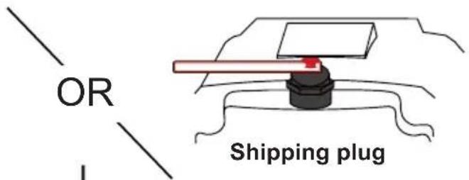
- Use the appropriate bladed screw driver, Allen wrench, or wrench to remove the shipping cap (usually RED) from the top of the pump.

natural_image
Diagram showing a red object on a surface with circular motion arrows indicating rotation (no text or symbols)- Hand thread the breather cap into the pump.
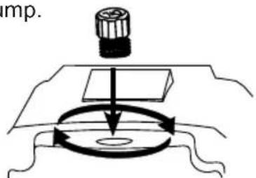
-
Snug the cap with your fingers.
-
Grasp the label and remove both it and the RED shipping plug.

natural_image
Diagram of a mechanical press or lever system with a rotating arrow indicating motion (no text or symbols present)- The breather is now open properly.

natural_image
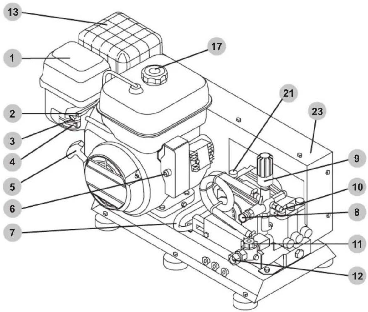
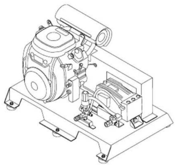
Simple line drawing of a mechanical component with a cylindrical base and rectangular block on top (no text or symbols)SINGLE CYLINDER BELT DRIVE
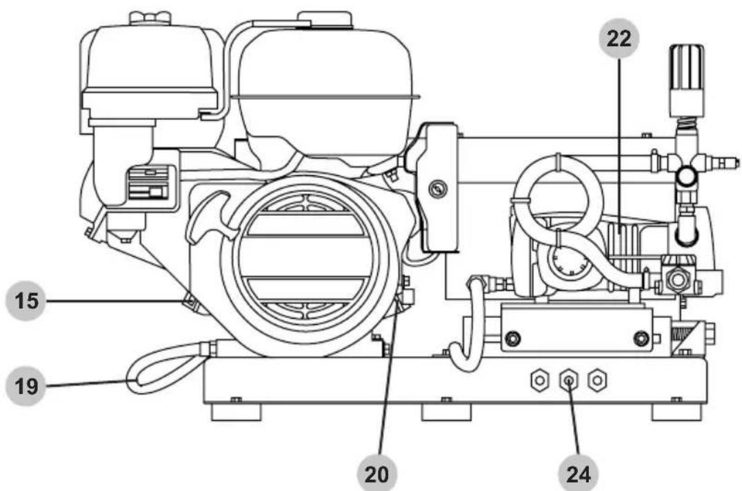
TWIN CYLINDER GEAR DRIVE

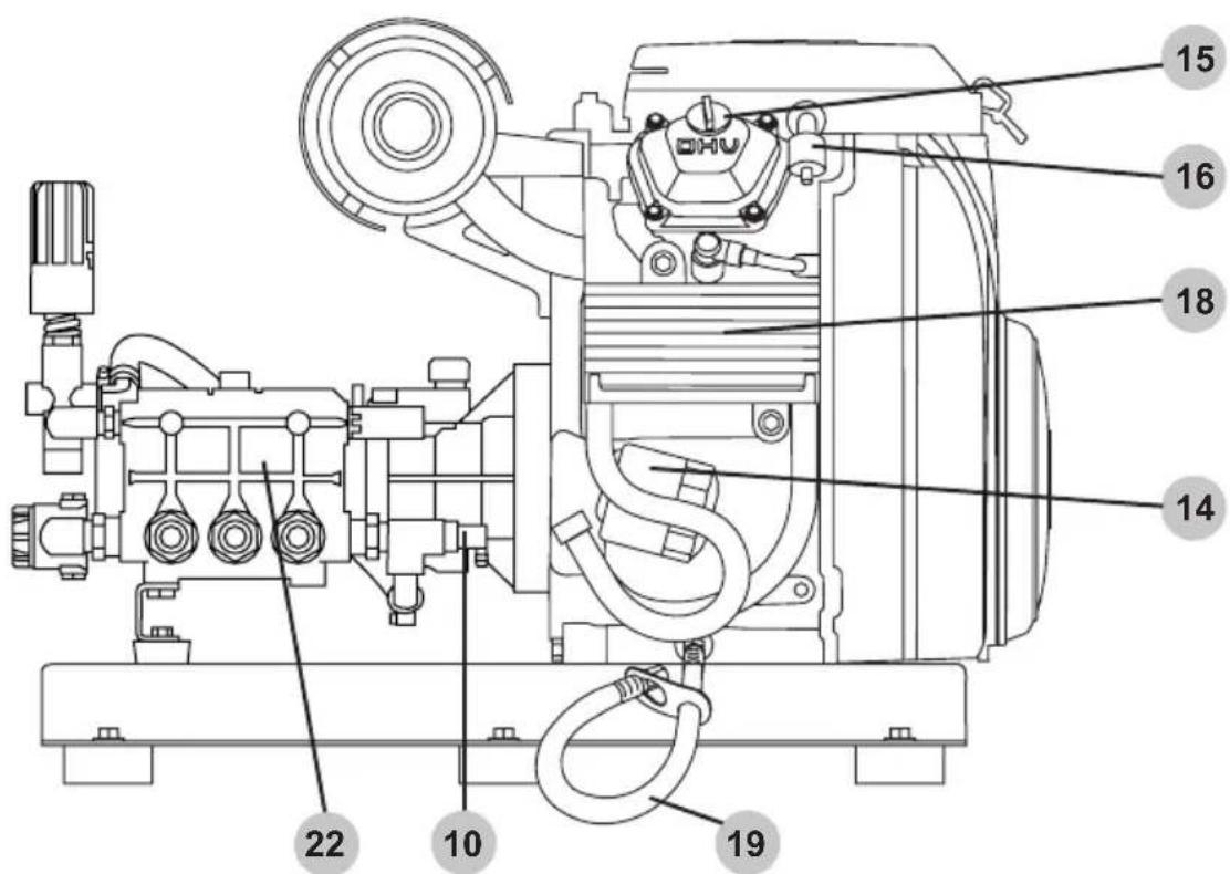
TWIN CYLINDER BELT DRIVE

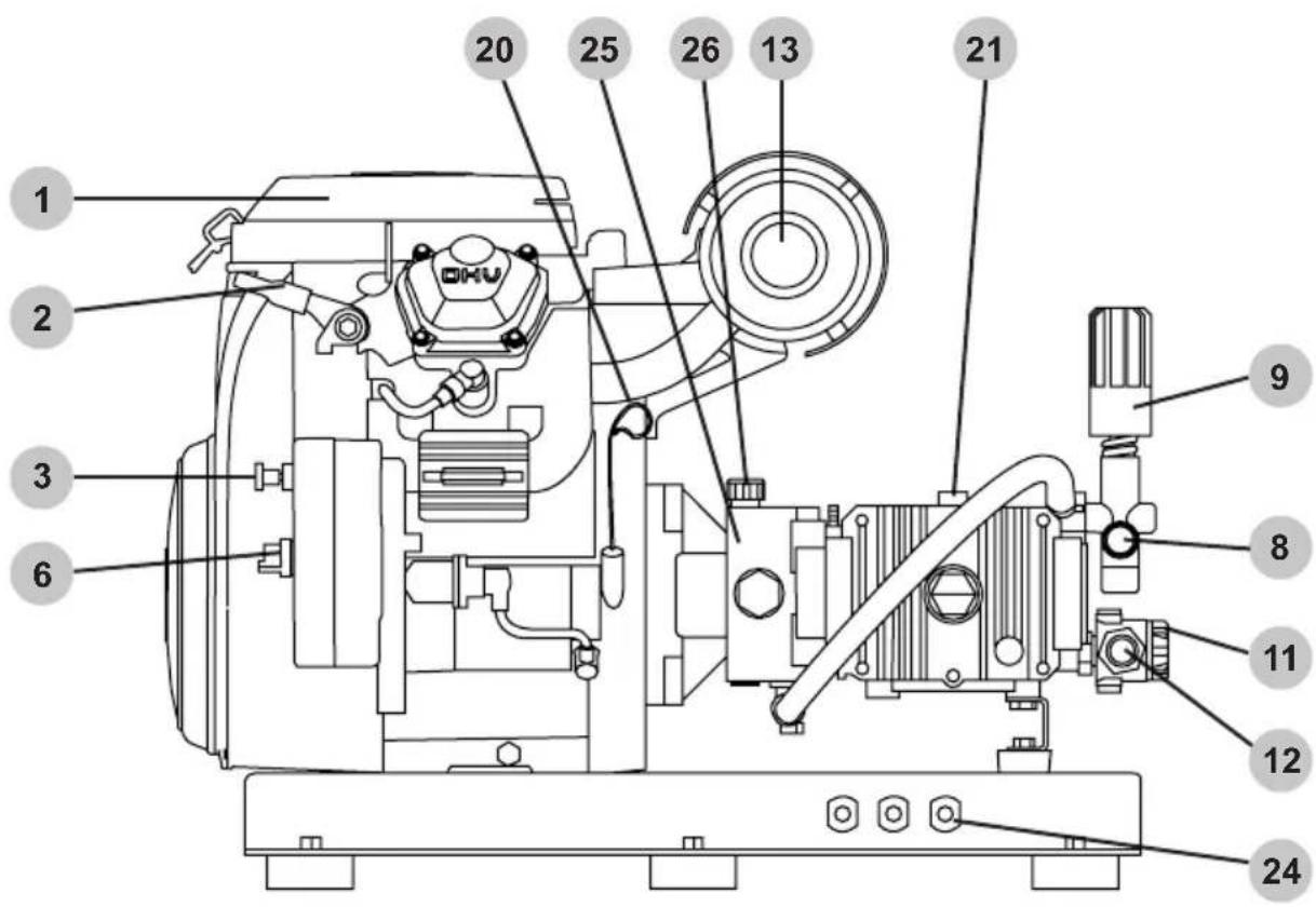
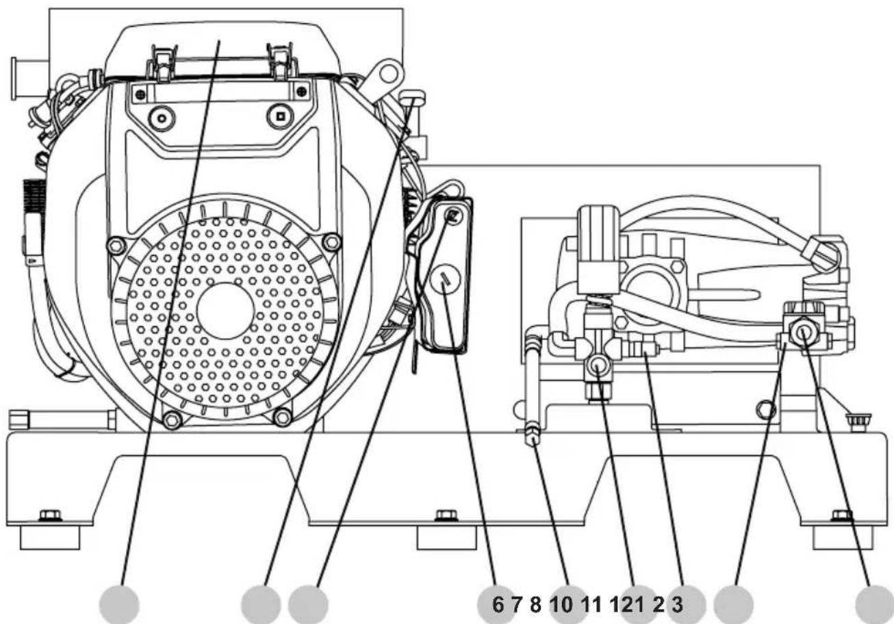
- Air filter housing cover
- Engine throttle lever (if equipped)
- Engine choke control (if equipped)
- Engine fuel valve lever (if equipped)
- Engine starting recoil (if equipped)
- OFF-ON-START key switch
- Pump oil drain hose (if equipped)
- High-pressure pump outlet
- Unloader hand control knob
- Thermal relief valve
- Water filter housing
- Garden hose coupler
- Engine muffler
- Engine oil filter (if equipped)
- Engine oil fill cap (verify location in the engine owner's manual)
- Engine fuel filter (if equipped)
- Engine fuel filler cap (if equipped)
- Engine oil cooler (if equipped)
- Engine oil drain hose
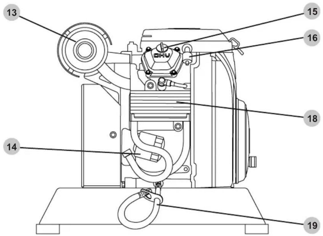

- Engine oil dipstick (verify location in the engine owner's manual)
- High-pressure pump oil fill
- High-pressure pump
- Outer belt guard (if equipped)
- Nozzle holders
- Pump gearbox (if equipped)
- Pump gearbox oil fill (if equipped)
CONNECTING HOSES (not included)
Before connecting a water supply hose, the water supply must provide an uninterrupted source of clean, cold water of at least the rated gallons per minute (GPM) of the pressure washer and 20 pounds per square inch (PSI) of pressure. However, we recommend that the water supply is at least 10% above the rated GPM of the pressure washer. Once a proper water supply is secured, follow the instructions below to connect both the water supply and high-pressure hoses to the pressure washer. DO NOT use hot water. Use cold water only.
- Verify the inlet screen is free of any dirt or debris and is in place with the convex side facing out.

natural_image
Technical illustration of a mechanical component with a meshed circular base and a hexagonal nut (no text or symbols)- Turn on the water supply and run for 30 seconds to purge any debris from the supply hose. Then, turn off the water supply and thread the water supply hose into the pump inlet.

natural_image
Technical line drawing of a connector with threaded ends and a hexagonal nut inserted (no text or symbols)- While pulling back on the pump outlet collar, insert the hose connector then release the collar. Gently tug on the hose to make sure it is locked.

- While pulling back on the hose outlet collar, insert the spray gun connector (not included) then release the collar. Gently tug on the hose to make sure it is locked.

natural_image
Technical line drawing of a mechanical component with an arrow indicating assembly or transformation (no text or symbols present)
NOTICE
PUMP PURGING
Running a pressure washer pump without water will severely damage the pump seals and other internal components. To avoid this hazard, make sure your water supply is uninterrupted and at least the rated GPM of the pressure washer and at least 20 PSI, and always purge the air your pressure washer pump before starting the engine.

WARNING:
INJECTION INJURY
The high pressures created by a pressure washer can cause fluid injection injuries, severe lacerations, amputations, and / or death. To avoid these hazards, always aim the spray gun and lance in a safe direction when using the pressure washer and never attempt to touch a leak in a high-pressure hose or fitting.
A pressure washer pump is designed to operate with water flowing through it. Water lubricates and cools the internal components of the pump. Running a pressure washer pump without water will severely damage the pump seals and other internal components. Damage caused by running a pressure washer pump without water is not covered under warranty. Be sure to follow the instructions below to correctly purge the air from your pressure washer pump before starting the engine.
-
Connect all the hoses by following the steps outlined in the CONNECTING HOSES section of this manual then turn on the cold water source.
-
Aim the spray gun (not included) in a safe direction then squeeze and hold the trigger for at least 30 seconds or until the water runs steady and all the air is purged from the pump and hoses.

natural_image
Line drawing of a fuel pump component with hoses and connectors (no text or symbols)- Check hoses and connections for leaks. If leaks are found, turn off the machine, aim the spray gun in a safe direction and squeeze the trigger to relive any built up pressure in the system. Never attempt to touch a leak in a high-pressure hose or fitting. Never attempt to repair a high-pressure hose.
Engage the trigger lock.4.
Nozzle Selection
The nozzles supplied with the pressure washer have specific spray patterns designed to clean different surfaces. Using the incorrect nozzle can damage surfaces. Refer to the table below to select the correct nozzle before using the pressure washer. NOTE: The selection of nozzles included may vary with pressure washer models.
| Color | Spray Pattern | Uses | Surfaces |
| Red | Spot cleaning hard, unpainted surfaces and high-reach areas | Unpainted metal and concreteDO NOT use on wood. | |
| Yellow | Intense cleaning of unpainted surfaces | Grills, driveways, concrete and brick walkways, unpainted brick and stucco | |
| Green | Standard cleaning nozzle for most applications | Yard tools, sidewalks, lawn furniture, unpainted siding, stucco, gutters, eaves, concrete, and brick surfaces | |
| White | Cleaning painted or delicate surfaces | Auto, truck, RV, marine, wood, painted brick, painted stucco, vinyl, and painted siding | |
| Black | Applies cleaning solutions | Safe on all surfaces. Always verify compatibility of cleaning solution(s) prior to use. |

NOTICE
SPRAY DAMAGE
High-pressure spray can damage plants and other surfaces such as wood, glass, automobile paint, auto striping and trim, and delicate objects. To avoid causing damage, cover plants before spraying near them, refer to the Nozzle Selection table in this manual for correct nozzle selection, and test surfaces before spraying to make sure they are strong enough to withstand high-pressure spray.
Nozzle Installation
If the engine is running, make sure the trigger lock is in the locked position before removing and installing nozzles.
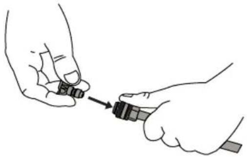
To place a nozzle into the spray wand, pull the quick-connect coupler back, insert the nozzle, then release the coupler allowing it to snap back in place. Once installed, pull on the nozzle to make sure it is secure.
natural_image
Illustration of two hands using a tool to adjust or install a small object (no text or symbols present)
OPERATING CHECKLIST
Attempting to start the engine incorrectly or using the pressure washer incorrectly can result in engine and/or pressure washer damage, and may cause serious injury or death. To avoid these hazards, be sure to read, understand, and follow the steps outlined in the OPERATING CHECKLIST section of the owner's manual before starting the engine, and follow all the guidelines for proper use of the pressure washer.
Location
Place the pressure washer on a level surface outside in a well-ventilated area before operating. Keep all flammable materials at least five feet away from all sides of the product.
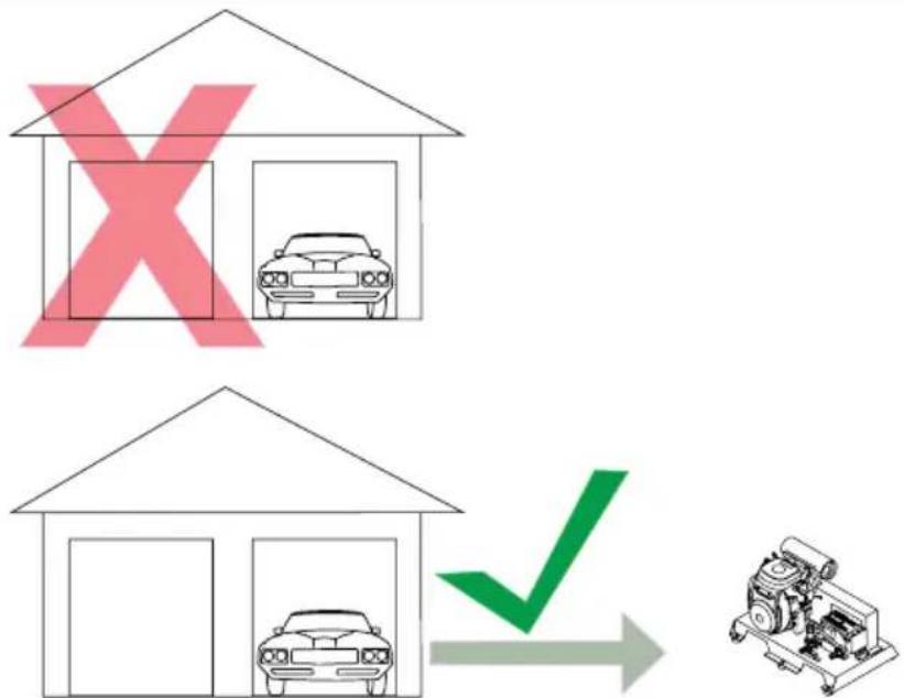
- Never use pressure washer inside a house, garage, or any other kind of enclosure even if doors and windows are open. Run engine outside at least 20 feet (6 meters) away from windows, doors, and vents. Carefully consider wind direction and air currents when using pressure washer outside to avoid breathing in engine exhaust.
- Following the manufacturer's instructions and recommendations, install battery operated carbon monoxide alarms in any occupied buildings near the running engine.
- If you experience headache, nausea, dizziness, sleepiness, or weakness while pressure washer is running, move to fresh air and seek medical attention immediately.


TOXIC FUMES
Engine exhaust contains carbon monoxide, an odorless, colorless, poisonous gas. Running an engine indoors will kill you in minutes. Never use this product inside a house, garage, or any other kind of enclosure even if doors and windows are open. Run engine outside at least 20 feet (6 meters) away from windows, doors, and vents. Carefully consider wind direction and air currents when using this product outside to avoid breathing in engine exhaust. Always use a carbon monoxide detector in any occupied buildings near the running engine.
High Altitude Operation (Non-EFI models, only)
This engine will have proper engine performance and emission control when it is operated at or below an altitude of 5000 feet (1524 meters). This engine requires a high-altitude carburetor kit to ensure proper engine performance and emission control when operated at altitudes above 5000 feet (1524 meters). Operating the machine with the wrong engine configuration above 5000 feet (1524 meters) may increase its emissions, decrease fuel efficiency, and hurt performance. To obtain a high altitude carburetor kit, contact your nearest authorized service center.

NOTICE
ALTITUDE
Operating the engine with a high-altitude carburetor jet kit at an altitude below 5000 feet (1524 meters) will cause the engine to run too hot. Overheating the engine could result in serious engine damage. To avoid this hazard, make sure the correct carburetor kit is installed and the air/fuel mixture is set correctly for your altitude.
Operating Conditions
Before each use, check for loose or damaged parts, leaks, and/or any other condition that may affect proper operation. Repair or replace all damaged and/or defective parts with authorized parts immediately. Do not operate the machine with missing, broken, or unauthorized parts. Always keep all safety guards in place and in proper working order. For safety reasons, the manufacturer recommends all maintenance and repairs be performed by an authorized service center. Never compromise the safety features of this product.
Before starting engine, remove any excessive dirt and debris from cooling vents, exhaust, and starter recoil areas. Always operate the pressure washer on a level surface and never move or tip the pressure washer while operating. Use pressure washer only for its intended purpose. Never pull water supply hose or high-pressure hose to move pressure washer. This could damage hose, pump inlet, and/or pump outlet. If you have questions about the proper use of your pressure washer, please contact customer support at 1-833-362-7368 or cservice@fna-group.com.


CHILDREN AND UNTRAINED ADULTS
Do not allow children or untrained adults to operate or play with the pressure washer as they can be seriously injured or killed. Anyone operating the pressure washer should receive proper instructions, understand safe operation, and thoroughly read the owner's manual before operating this product. Keep children and pets away from the pressure washer while it is running. Always turn off the pressure washer before leaving the area.


Failure to inspect this product before use could create a hazardous situation resulting in product damage, serious injury, and/or death. To avoid these hazards, inspect the pressure washer before each use. Check for loose or damaged parts, signs of oil or fuel leaks, missing guards, plugged cooling vents, or any other condition that may affect proper operation. Repair or replace all damaged or defective parts with authorized parts and keep all safety guards in place and in proper working order before using the pressure washer.


ELECTRICAL SHOCK
Spray directed at electrical receptacles or switches, or objects connected to an electrical circuit, could result in a fatal electrical shock. Direct spray away from electric receptacles, switches and equipment. Never clean any electrically operated device, even when disconnected, unless it clearly states in its manual that such cleaning is approved.


RISK OF BURSTING
High-velocity spray directed at pneumatic tire sidewalls (such as found on automobiles, trailers and the like) could damage the sidewall resulting in serious injury. On pressure washers rated above 1600 psi (11032 kPa) use the widest fan spray (40° nozzle) and keep the spray a minimum of 8" (20cm) from the pneumatic tire sidewall. Do not aim spray directly at the bead between the tire and rim.
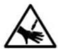

INJECTION INJURY
The high pressures created by a pressure washer can cause fluid injection injuries to human and animal flesh, severe lacerations, amputations, and/or death. To avoid these hazards, always aim the spray gun and lance in a safe direction when using the pressure washer and never attempt to touch a leak in a high-pressure hose or fitting. Never place hands in front of the nozzle. Never hold onto the hose or fittings during operation. Never attach or remove wand or hose fittings while system is pressurized. Never point wand at or spray people and/or animals. DO NOT TREAT FLUID INJECTION AS A SIMPLE CUT! See a physician immediately!
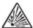


RISK OF EXPLOSION OR FIRE
Operating the pressure washer in an explosive environment could result in a fire. Operate and fuel equipment in well-ventilated areas free from obstructions. Equip areas with fire extinguisher suitable for gasoline fires.


HOT SURFACES
A running engine produces heat. The surfaces of the engine, other related components, and engine exhaust gas get hot enough to cause mild moderate burns or ignite materials on contact (such as siding, plastic, rubber, vinyl, or the pressure hose itself), and damage live plants. To avoid burns, do not touch engine surfaces or exhaust gases while operating and allow engine to cool completely before moving, touching, or performing any maintenance. To avoid a fire, keep all flammable materials at least five feet away from all sides of the product. Never cover the pressure washer during operation or directly after being used.

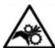
MOVING PARTS
This product has many parts that move at high speeds. Moving parts can cause crushing injuries, broken bones, severe lacerations, and/or traumatic amputations. To prevent injury, never place fingers, hands, feet, or other body parts near running engine. Never operate product with covers, shrouds, or other guards removed. Do not wear loose-fitting clothing, dangling drawstrings, or any other hanging items that could become entangled in moving parts while operating. Tie up long hair and remove jewelry before operating.


INJECTION INJURY
Risk of fluid injection. When using lance/spray gun combinations with this pressure washer, use a lance that is at least 31 inches in length.

PRESSURE RATING
Only use accessories or replacement parts rated equal to or higher than the rating of the pressure washer to prevent serious injuries, pressure washer damage and/or accessory damage.
Checking the Engine Oil


HOT OIL
Hot oil can cause serious burns. To prevent getting burned when changing or checking the engine oil, wear appropriate gloves and change the oil when the engine is warm but not hot.


LOW OIL SENSOR
The low oil sensor (if equipped) will automatically stop the engine when the oil level falls below the safe limit. To avoid an unexpected shutdown, check the oil level before each use, fill to the upper limit, and always operate engine on a level surface.

FILL ENGINE OIL BEFORE USE
The engine is shipped from the factory without oil. Running the engine without oil will result in severe engine damage and void the warranty. To avoid causing engine damage and voiding the warranty, fill the engine with the recommended oil type before starting.

USE CORRECT ENGINE OIL
Oil is a major factor in the performance and service life of any engine. Using the incorrect oil may damage the engine and void the warranty. To avoid causing engine damage and voiding the warranty, check and change oil as required using the correct engine oil.
- Check oil with pressure washer on a level surface and the engine off.
- Pull engine oil dipstick out of the engine, then wipe dipstick clean.
- Place clean dipstick fully into the dipstick tube.
- Remove the dipstick from dipstick tube and check oil level. Oil level should be between the upper and lower oil limits on the dipstick.
- If level is low, add the recommended oil to the crankcase until the level reaches the upper limit on the dipstick. See the engine manual for recommended oil.
- Place the dipstick fully into the dipstick tube.
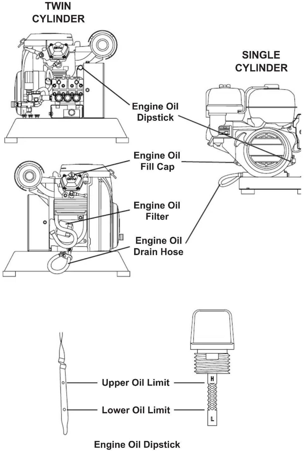
Engine Oil
Dipstick
Engine Oil Fill Cap
Engine Oil
Filter
Engine Oil
Drain Hose
* verify location of components in the engine owner's manual
Checking Fuel


WARNING:
REFUELING
Gasoline is highly flammable and gasoline vapors are extremely explosive. Fire and explosions can cause severe burns and/or death. Keep gasoline away from flames, sparks, and other ignition sources. Refuel outdoors in a well-ventilated area with the engine stopped and cool. Wipe up any spilled gasoline and allow engine to dry before starting. Keep a fire extinguisher handy while refueling. Do not operate engine with leaks in the fuel system. Do not store gasoline near other flammable materials. Store fuel in a clean, OSHA-approved container in a secured location away from the work area.
NOTICE
OLD GASOLINE
Old gasoline can create deposits that clog fuel systems causing hard starting and poor performance. Damage caused by old fuel is not covered by warranty. To minimize deposits, avoid old fuel related performance issues, and prevent costly repair work, do not use gasoline that is older than 30 days.

NOTICE
ALCOHOL BLENDS
Using gasoline with an alcohol blend greater than 10% (E10) will damage the engine. Damage caused by using an alcohol blend of 15% (E15), 85% (E85), or any other alcohol blend higher than 10% (E10) is not covered under warranty. To avoid engine damage caused by an alcohol blend that is too high, use gasoline with 10% (E10) alcohol or lower.
NOTICE
GASOLINE ADDITIVES
The use of fuel system cleaning additives can damage the engine and fuel systems. Damage caused by the use of fuel system cleaning additives is not covered by warranty. To avoid engine and fuel system damage, do not use any fuel system cleaning additives.
NOTICE
GASOLINE STORAGE
It is important to prevent gum deposits from forming in essential fuel system parts, such as the carburetor, fuel filter, fuel hose or tank during storage. Alcohol-blended fuels (also called gasohol, ethanol, or methanol) attract moisture, which leads to separation and formation of acids during storage. Acidic fuel and gum deposits can damage the engine's fuel system while in storage. Damage caused by the use of old, stale, or contaminated fuel are not covered under warranty.
NOTICE
DO NOT OVERFILL FUEL TANK
Overfilling the fuel tank can result in carbon canister damage (if equipped), poor engine performance, and void the warranty. To avoid these hazards, do not fill the fuel tank above the maximum level.
- Check fuel with the engine off and pressure washer on a level surface.
- Remove fuel tank cap, check fuel level, then fill fuel tank if needed.
- Do not use gasoline that is older than 30 days. Use only clean and fresh regular unleaded gasoline with a minimum octane rating of 87. Do not mix oil with gasoline. Do not use gasoline that contains more than 10% ethyl alcohol. E15, E20, and E85 are not approved fuels and should not be used.
- Do not fill the fuel tank above the maximum fuel level to allow room for fuel expansion.
- Replace fuel tank cap. Never run engine without fuel cap installed.
NOTE: Using a fuel stabilizer (sold separately) when storing gasoline can help prevent problems related to storing ethanol alcohol blended gasoline. Always follow the instructions provided by the fuel stabilizer manufacturer to mix and use correctly.


OPERATING CHECKLIST
Attempting to start the engine incorrectly or using the pressure washer incorrectly can result in engine and/or pressure washer damage, and may cause serious injury or death. To avoid these hazards, be sure to read, understand, and follow the steps outlined in the OPERATING CHECKLIST section of the owner's manual before starting the engine, and follow all the guidelines for proper use of the pressure washer.


PUMP DAMAGE
Running the pressure washer for more than two minutes without the spray gun trigger pulled will overheat the pump and possibly cause damage. The thermal relief valve will open and spray water to help cool the pump as it overheats. Never tamper with the thermal relief valve. To avoid overheating the pump, shut off the engine if not being used for longer than two minutes.
Starting the Engine
- Complete the steps in the OPERATING CHECKLIST section of this manual before starting the engine. Failure to do so could cause damage to the pump or engine. If needed, refer to your Engine Owner's Manual for specific starting instructions.
The water source should be connected, turned on, any air purged from the system, and the trigger lock placed in the locked position. - Slide the fuel valve to the ON position (if equipped).
- Slide the throttle to the RUN position (if equipped).
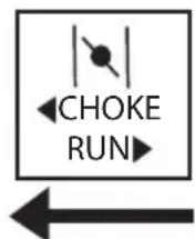
- If equipped, move the choke to CHOKE (closed) for starting a COLD engine. Move to RUN (open) for a WARM engine.
CLOSED
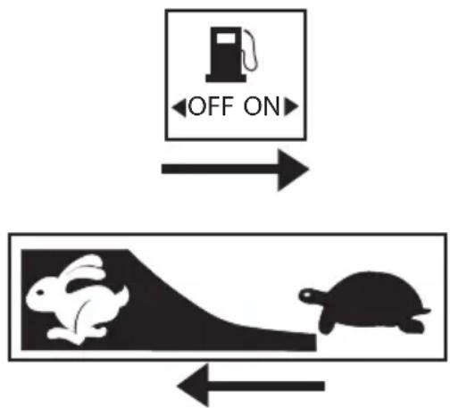
flowchart
graph TD
    A["OFF ON"] --> B["Cartoon Rabbit"]
    B --> C["Turtle"]


natural_image
Pure electrical circuit lines without any symbolsNOTE: The starting position of the choke will vary depending on the engine temperature. If starting a cold engine, move the choke lever towards the CLOSED position. If starting a warm engine, move the choke lever towards the OPEN position.
5A. (Electric start) Rotate the key past the ON position to the START position and hold until the engine starts. If the engine does not start after 5 seconds, release the key and allow the starter to cool for 1 minute before trying to start the engine once again. Allow the key to return to the ON position once the engine starts.


SPRAY DAMAGE
Allowing the starter to constantly crank will damage the starter! If the engine does not start after two attempts, refer to the TROUBLESHOOTING section for help.
5B. (Manual start) If equipped, pull the recoil slowly until resistance is felt, then pull rapidly to start the engine. Do not allow the starter grip to snap back. Return it gently by hand.

natural_image
Simple line drawing of a hand gripping a screwdriver with three upward arrows (no text or symbols)NOTE: If the engine should not start after two pulls, squeeze the gun trigger to release stored pressure. Then, try again to start the engine.

RAPID RETRACTION
Rapid retraction (also known as kickback) of the engine recoil starter cord will pull your hand and arm towards the engine faster than you can let go of the handle resulting in sprains, broken bones, lacerations, and/or traumatic amputations. Kickback is often caused by internal engine failure, and/or improper starting techniques. To avoid kickback follow the appropriate maintenance schedule, starting instructions and have repair work done by an authorized service center.
- Once the engine starts, slowly move the choke lever (if equipped) to RUN (open) as the engine runs. If the engine falters, move the choke toward CHOKE (closed) until the engine has warmed up.

- Allow engine to warm for 1-2 minutes before using the product, occasionally pulling the spray gun trigger to allow water to flow through the pump and avoid overheating and causing damage to the pump.
NOTE: Always secure trigger lock when spray gun is not in use to prevent accidental operation. Never permanently secure trigger in pull-back (open) position.
NOTICE
PUMP DAMAGE
Turning off the water supply to your pump with the engine running will damage the pump. Damage caused by running the pump without water is not covered under warranty. To avoid this hazard always turn off the engine before shutting off the water supply.
- Set the trigger lock on the spray gun.
- Slide the throttle to the SLOW position (if equipped).
- Turn the engine switch to the OFF position.
- Slide the fuel valve to the OFF position (if equipped).
- Turn off the water supply.
- Release the trigger lock then squeeze the spray gun trigger to relieve the pressure in the hose and pump.
- Allow the engine to cool completely before handling and storage.
OPERATION TIPS
Terms
- PSI - Pounds per square inch (PSI) is the unit to measure the pressure of water. In relation to a pressure washer, the higher the PSI number, the greater the pressure and stripping power produced.
- GPM - Gallons per minute (GPM) is the flow rate of water. In relation to a pressure washer, the greater the GPM, the greater the flow or rinsing power produced.
- CU - Cleaning units express the efficiency of the pressure washer. Cleaning units are calculated by multiply the PSI by the GPM. The higher the CU, the more efficient the pressure washer.
Preparation
- Read all warning and instructions in this and all manuals that came with the pressure washer.
- Remove all toys, bikes, lawn furniture, etc. from the work area if they are not to be cleaned.
- Sweep any loose dirt and debris from the surface you will be pressure washing.
-
Cover nearby plants to avoid damaging them with the pressure washer spray.
-
Use caution when spraying windows. Always use the white, 40 ^® nozzle and stay at least 4 feet away.
- Lay tarps down to collect paint chips and other debris blown off by the spray. Exterior paints used before 1977 may contain lead and will produce chips that will need to be collected and disposed of at a hazardous waste facility.
- To minimize water infiltration to the pressure washer motor, locate the pressure washer as far as possible from the cleaning site during operation.
Pressure Washing
- A wider spray equals faster cleaning, while a tighter spray equals deeper cleaning.
- Keep the nozzle about 4 feet away from siding to avoid damage.
- Start washing siding at the bottom and work your way up, then rinse from the top down.
- Avoid driving water up behind siding.
- Use overlapping strokes for even cleaning.
• Work in small areas to keep the soap from drying.
- Do not aim the nozzle straight at the surface. Hold the wand at a 45^ angle to the surface at a distance that cleans well without causing damage.
Adjusting Surface Pressure
- Back away from the surface to be cleaned. The further you position the nozzle from the surface to be cleaned, the lower the pressure to reach the surface.
- Change to the white, 40^ nozzle. This nozzle produces a lower pressure, wider width spray.
Adjusting Unloader Hand Control Knob to Adjust Pressure


HIGH PRESSURE
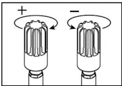
Do not remove the unloader hand control knob. Do not overtighten the unloader hand control knob. Overtightening the knob past the built-in stop may result in serious injuries, the knob breaking and/or costly repairs. Do not attempt to increase the pressure past the factory preset pressure.
The highest pressure setting is preset at the factory to achieve optimum pressure for cleaning. If you should need to lower the pressure, your unit may be equipped with an unloader hand control knob that allows you to adjust the pressure. The unloader hand control knob style may differ from those shown below.
- If equipped with an unloader hand control knob, lower the pressure by turning the unloader hand control knob counter-clockwise to the desired pressure.
- Turn the unloader hand control knob clockwise until it stops to return to the highest pressure setting preset at the factory.

natural_image
Diagram of two types of LED connectors with polarity signs, showing internal structure and rotation arrows (no text or symbols)| ISSUE POSSIBLE CAUSE SOLUTION | ||
| Engine will not start.Refer to the Engine Owner's Manual for more engine troubleshooting information. | The fuel tank is empty. Add | fresh fuel. |
| Water pressure in the pump is preventing the engine from rotating. | Aim the spray gun in a safe direction then pull the trigger to release water pressure in the pump. | |
| Engine choke is in the wrong position. | Refer to the STARTING ENGINE section of this manual for the correct choke position. | |
| The spark plug lead is not attached to the plug. | Connect spark plug lead. | |
| Engine switch is in the OFF position. | Turn the engine switch to the ON position. | |
| Engine fuel valve is turned OFF. | Turn fuel valve ON. | |
| Engine oil is low. If the engine is equipped with a Low Oil Sensor, the engine will not start. | Check engine oil level. Fill per engine manual. | |
| The pressure washer creates low or no water pressure. | There is air trapped in the pump and/or hoses. | Refer to the PURGING THE PUMP section of this manual to remove air from the pump and hoses. |
| Water source is insufficient. | Make sure the water source can supply at least the rated GPM of the pressure washer at 20 PSI. | |
| The nozzle is clogged. | Clean nozzle per the MAINTENANCE section of this manual. | |
| The water inlet screen is clogged. | Clean the water inlet screen per the MAINTENANCE section of this manual. | |
| The high-pressure hose is too long. | The high-pressure hose should be less than 100 feet in length. | |
| Engine choke is in the CHOKE position. | Move engine choke to the RUN position. | |
| Will not draw in detergent. | Chemical build up in chemical injector. | Contact customer service at 1-833-362-7368 or at cservice@fna-group.com |
| Will not draw in detergent (continued) | Spray wand not in low pressure. | Insert black “soap” nozzle. |
| Detergent filter clogged. | Clean the filter. | |
| Detergent filter is not submerged in the detergent. | Make sure the filter end of the detergent siphon hose is fully submerged in the detergent. | |
| Detergent is too thick. | Dilute detergent. The detergent should be the same consistency as water. | |
| High-pressure hose is too long. | Lengthen the water supply hose and shorten the high-pressure hose. | |
| Detergent is dried inside of the detergent injector. | Contact customer service at 1-833-362-7368 or at cservice@fna-group.com | |
| Water leaking at pump. | Loose connections. | Tighten the connections. |
| Worn or torn O-ring. | Check and replace. | |
| Piston packing worn. | Contact customer service at 1-833-362-7368 or at cservice@fna-group.com | |
| Pump head or tubes damaged from freezing. | Contact customer service at 1-833-362-7368 or at cservice@fna-group.com | |
| Pump or nozzle pulsates. | Nozzle obstructed. | Clean nozzle per the MAINTENANCE section of this manual. |
| Oil leaking from pump. | Loose drain plug. | Tighten. |
| Worn drain plug O-ring. | Check and replace. | |
| Worn fill plug O-ring. | Check and replace. | |
| Pump oil overfilled. | Check for correct amount. | |
| Incorrect oil used. | Drain and fill with correct type and amount of oil. | |
| Vent plug is clogged. | Clean vent plug; blow air through vent to remove blockage. If problem persists, replace the plug. | |
| Oil seals worn. | Contact customer service at 1-833-362-7368 or at cservice@fna-group.com | |
| Water leaking at gun/spray wand connection. | Worn or broken O-ring. | Check and replace. |
| Loose hose connection. | Tighten. | |
For additional help or to find your local authorized service location, call 1-833-362-7368 or email cservice@fna-group.com.
For safety reasons, the manufacturer recommends all pressure washer service and repairs be performed by an authorized service center. All warranty replacements or repairs must be performed by an authorized distribution or service center. To find an authorized service center near you, make a warranty claim, or get authorized warranty repair, call 1-833-362-7368 or email cservice@fna-group.com.
It is the responsibility of the owner and/or operator to have all scheduled maintenance completed before operating the pressure washer. Be sure to follow the inspection and maintenance recommendations as listed in all the manuals that came with this unit.
Maintenance
Before each use, check pressure washer for leaks, loose or damaged parts, and any other condition that may affect proper operation. Be sure all safety guards are in place and in proper working order. Inspect all air vents and cooling slots to ensure they are clean and unobstructed. Repair or replace all damaged or defective parts with authorized parts immediately. For safety reasons, the manufacturer recommends all pressure washer service and repairs be performed by an authorized service center. Never attempt to repair a high-pressure hose.


RISK OF BURNING
When performing maintenance, you may be exposed to hot surfaces, water pressure, or moving parts that can cause serious injury or death.


RISK OF FIRE
Always disconnect spark plug wire, let the engine cool, and release all water pressure before performing any maintenance or repair. Injuries can result if system pressure is not reduced before attempting maintenance or disassembly. The engine contains flammable fuel. Do not smoke or work near open flames while performing maintenance.


MODIFICATION INJURY
Never modify the product or any part of it. Damage or personal injury could result.
Cleaning the Pressure Washer
Always clean the pressure washer with the engine off and cool. To clean the pressure washer, first use an air compressor set at no more than 25 PSI to clear dirt and debris from the pressure washer surfaces, vents, and cooling slots. Then, wipe the exterior clean with a damp cloth.

NOTICE
CLEANING
Water can damage the pressure washer engine components if allowed to enter through cooling slots or other holes. Damage caused by water intrusion is not covered under warranty. To avoid engine water damage, do not use a pressure washer, garden hose, or any other sources of running water to clean the pressure washer engine, and never submerge the pressure washer engine in any liquids.
NOTICE
CHEMICAL CLEANERS
Using chemical cleaners and/or corrosive liquids can damage the pressure washer seals and internal components. Damage caused by chemical cleaners and corrosive liquids is not covered under warranty. To avoid these hazard, only used approved cleaning chemicals, never use bleach, and always run clean water through the pressure washer after using cleaning chemicals.
Connections
Hose, spray gun, and pump connections should be cleaned and lubricated with a thin film of lithium grease regularly to prevent o-ring damage and leaks.
Nozzle Cleaning
If a nozzle becomes clogged, the pump may pulsate and spray patterns could change. If the nozzle is not cleaned, excessive pressure may develop possibly damaging the pump, or other accessories. Inspect nozzles before using them and follow the instructions in this section for the proper nozzle cleaning procedure.
- Shut off the pressure washer.
- Turn off the water supply.
- Point the spray gun in a safe direction and squeeze the trigger to relieve water pressure.
- Set the trigger lock.
- Remove the nozzle from the lance quick connector.
- Clear any obstructions from the nozzle by inserting the nozzle cleaning tool provided.

natural_image
Diagram showing a mechanical component with a circular end connected to a cylindrical shaft, illustrating displacement or assembly (no text or symbols present)- Rinse any loose debris from the nozzle by directing a running garden hose into the output of the nozzle for at least 30 seconds.

Water Inlet Filter
Before each use, check the screen inlet filter and clean by following the steps below. Never operate the pressure washer without the screen inlet filter properly installed.
- Remove the filter from the garden hose coupler.
- Use water from a running garden hose to clean both sides of the filter.
- Insert the cleaned filter into the pump inlet with the convex side facing out.

natural_image
Technical illustration of a mechanical component with a meshed circular base and threaded end (no text or symbols)The blue cap filter should be checked periodically to be determined if cleaning is required.

natural_image
Technical line drawing of a valve with a curved arrow indicating rotation (no text or symbols)- With the water sourced turned off, unscrew the housing cover on the top of the water filter.

natural_image
Diagram of a valve assembly with a threaded cap and hexagonal base, showing an upward arrow (no text or symbols)- Remove any debris from around the mesh screen, inside the housing and the cover.

natural_image
Pure mechanical diagram showing a valve or connector with arrows indicating flow direction (no text or symbols)- With the garden hose connected, turn on the water for few seconds to flush any debris that may be retained within the housing.

natural_image
Diagram of a valve assembly showing a handle, nut, and bolt with directional arrows indicating motion (no text or labels)- Thread the housing cover into the top of the water filter housing; hand tighten.
Pump Maintenance
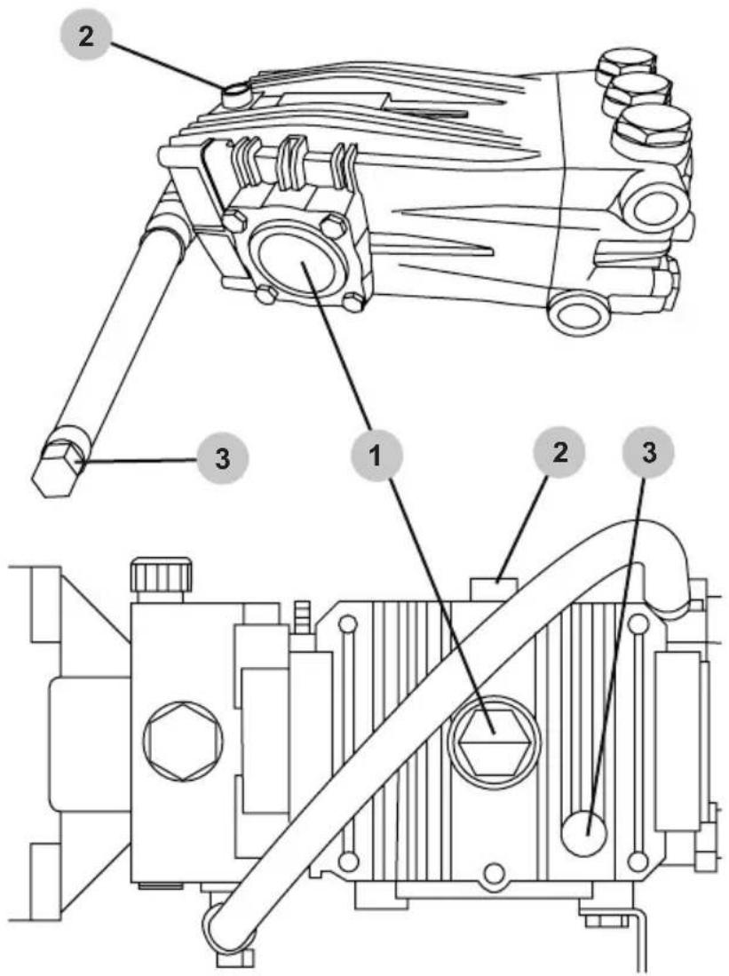
Note: The pump was filled with oil at the factory. Refer to your pump manufacturer for the proper recommended oil and oil change intervals.
- Oil sight glass
- Oil fill plug / vent cap
- Oil drain hose / Oil drain plug
How to Change the Pump Oil
- Loosen the pump oil fill plug / vent cap.
- Place a container under the plug on the oil drain hose.
- Remove the oil drain hose plug.
- After the oil has drained, insert the oil drain hose plug; tighten securely.
- Refer to your pump manufacturer for the proper recommended oil.
- Refill, making sure the proper oil level is met in the sightglass, or the maximum level marked on the dipstick, as recommended by the pump manufacturer.
- Insert the oil fill plug / vent cap; tighten securely.
*Illustrations are for reference only and may not represent your specific model.
Pump Gearbox Maintenance (if equipped)
Note: The pump gearbox was filled with oil at the factory. The preferred oil is a full-synthetic SAE 75W-90 oil. Change the oil after the first 50 hours of operation, and every 1000 hours thereafter or once a year.

- Oil sight glass
- Oil fill plug / vent cap
- Oil drain plug
How to Change the Pump Gearbox Oil
- Loosen the gearbox oil fill plug / vent cap.
- Place a container under the plug.
- Remove the oil drain plug.
- After the oil has drained, insert the oil drain plug; tighten securely.
- Refill with a full-synthetic SAE 75W-90 oil.
- Make sure the oil level meets but does not exceed the dot in the center of the sightglass.
- Insert the oil fill plug; tighten securely.
Belt Maintenance (if applicable)
Maintaining the proper amount of tension on the belts prolongs the life of the belts while assuring the proper operating parameters are met. The easiest way to determine the tension is by measuring the amount of deflection in the belts.
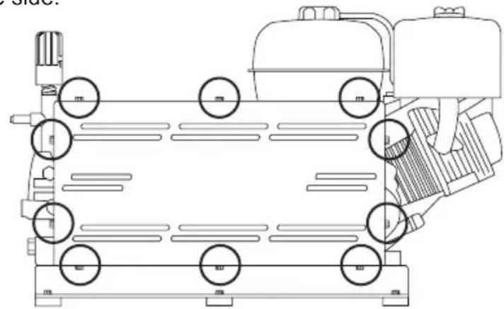
Removing the belt guard
- Disconnect the spark plug leads from the spark plugs. Allow them to hang away from the spark plugs.
- Using a 3/8" nut driver, loosen then remove the mounting bolt(s) on the top, bottom, and/or sides of the outer belt guard. Remove the outer belt guard from the frame; place it to the side.
natural_image
Technical line drawing of a vehicle chassis with wheels and structural components (no text or symbols)
natural_image
Technical line drawing of a mechanical assembly with no visible text or symbolsMeasuring the belt deflection
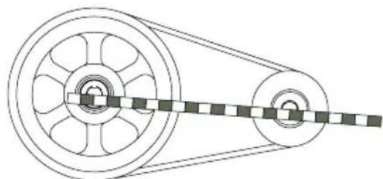
- With the use of a tape measure or yard stick, measure from the center of the engine shaft to the center of the pump shaft. Multiple this measurement by 1/64. For example, a measurement of 12" multiplied by 1/64 equals 0.1875" (3/16"). This measurement is the maximum amount of deflection you should measure in the belts.
natural_image
Technical line drawing of a pulley system with two wheels and a belt drive (no text or symbols)- Place a straight edge on top of the belts. Using your index finger, push down on the belts centered between the sheaves. With a ruler, measure the distance between the top of the belts and the bottom of the straight edge. If the measurement exceeds the calculation in Step #3, the belts need to be tightened.

natural_image
Technical line drawing of a pulley system with belt and wheel components (no text or labels)Adjusting the pump tensioner
-
Using a 9/16" wrench, loosen the carriage bolts on either side of the pump tensioner. Do not completely remove carraige bolts.
-
Using a 15/16" wrench, turn the bolt clockwise to tighten the belt. Should the belt need to be loosened, turn the bolt counter-clockwise.

natural_image
Technical line drawing of a mechanical component with arrows indicating assembly or movement (no text or symbols)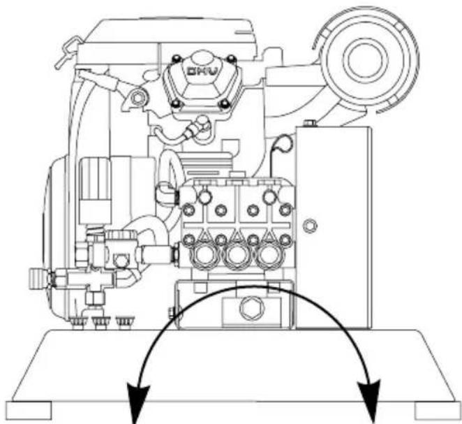
natural_image
Technical line drawing of a mechanical device with no visible text or symbolsTightenLoosen
-
Once the proper belt tension has been achieved, tighten the carriage bolts on the pump tensioner using a 9/16" wrench.
-
Slide the belt guard into place. Thread in the mounting bolts then tighten with a 3/8" nut driver.
-
Reconnect the spark plug leads.
Engine Maintenance
Before each use, check engine for loose or damaged parts, signs of oil or fuel leaks, and/or any other condition that may affect proper operation. Always keep all safety guards in place and in proper working order. Repair or replace all damaged or defective parts immediately.
For safety reasons, the manufacturer recommends all engine service and repairs (including emission control devices and systems) be performed by an authorized service center. All warranty replacements or repairs must be performed by an authorized distribution or service center. To find an authorized service center near you, obtain information about how to make a warranty claim, or to make arrangements for authorized warranty repairs, please call 1-833-362-7368 or email cservice@fna-group.com.
For all other information on engine maintenance, refer to the engine manual.
STORAGE AND TRANSPORTATION
Storing for Two Months or Less
- Fill fuel tank per the OPERATING CHECKLIST section of this manual then add a fuel stabilizer per the manufacturer's recommendations. NOTE: Using a fuel stabilizer (sold separately) when storing gasoline may help prevent problems related to alcohol blended fuels in outdoor power equipment engines. Always follow the instructions provided by the fuel stabilizer manufacturer to mix and use correctly.
- Complete the steps in the OPERATING CHECKLIST, CONNECTING HOSES, and PRIMING THE PUMP sections of this manual.
- Start the engine per the STARTING section of this manual and run it for ten (10) minutes to allow the stabilized fuel to circulate through the entire fuel system. Be sure to squeeze the trigger to keep water flowing through the pump and spray gun to avoid overheating.
- Turn the engine switch to the OFF position.
- Shut off the water supply. Remove the water supply hose.
- Squeeze the spray gun trigger to relieve the pressure in the hose and pump then drain the high pressure hose. Disconnect the high-pressure hose from the pump and spray gun.
- Allow the engine to cool completely.
- Protect the pump by using SIMPSON® Pump Guard per the USING PUMP GUARD section of this manual.
- Store the pressure washer in a clean, dry area out of direct sunlight.
Storing for More Than Two Months
- Make sure the engine is completely cool.
- Remove all the fuel from fuel tank, fuel lines, and carburetor by loosening the drain screw at the bottom of the fuel tank, and draining fuel into an appropriate container.
- Change the engine oil.
- Remove any dirt and debris from the area around the spark plugs, then use a spark plug socket or wrench to remove the spark plugs.
- Pour .5 ounces (15 ml) of new oil into the engine combustion chambers, then turn the starter to START for one second to distribute oil and lubricate the cylinders.
- Install the spark plugs.
- Disconnect the black, negative (-) battery lead from the battery (if equipped).
- Disconnect the red, positive (+) battery lead from the battery (if equipped).
- Drain the high-pressure hose.
- Using SIMPSON Pump Guard or an equivalent is recommended when storing the unit for more than 30 days and/or when freezing temperatures are expected.
- Store the pressure washer in a clean, dry area out of direct sunlight.
Transportation

TRANSPORTATION
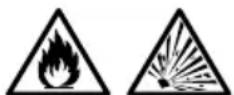
Leaving the pressure washer in an enclosed space where temperatures can rise on a transport vehicle may cause fuel to vaporize and possibly explode. Fire and explosions can cause severe burns and/or death. To avoid leaking or vaporizing fuel, secure the pressure washer in a well ventilated area out of direct sunlight and other heat sources and do not transport the pressure washer on rough roads unless the fuel has been drained beforehand.
- Turn the engine control switch to the OFF position.
- Slide the fuel valve to the OFF position (if equipped).
- When loaded onto a vehicle, if not intending to bolt to transport vehicle, secure pressure washer with straps or tie downs to prevent tip over and damage from sliding.
- Make sure the fuel containment system is secured and not allowed to move.

NOTICE
PUMP DAMAGE
Leaving water inside the pump during freezing weather will cause severe damage to the pump. To avoid costly damage, always treat the pump with SIMPSON® Pump Guard to remove the trapped water and to fill the pump with a lubricating, antifreeze solution.
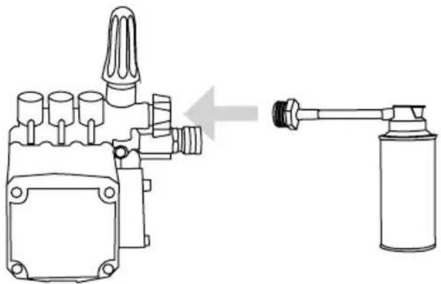
SIMPSON® Pump Guard (purchase separately) is formulated to protect your pump during long-term storage and from freezing damage. Pump Guard should be used throughout the season to keep the seals pliable and well lubricated. Before storing the unit for winter or for when there is a chance of freezing weather, use pump guard to remove all traces of water from the internal cavities while filling them with an antifreeze solution. Pump Guard is insurance for your investment, use it.
Simply use Pump Guard by following these easy steps:
- Screw the Pump Guard adapter into the garden hose input on the pump.
natural_image
Technical line drawing of a mechanical device with a pipe fitting and a cylindrical container (no text or symbols)- Press and hold down on the button until all the water and the Pump Guard starts to come out of the high pressure port.

natural_image
Diagram of a mechanical device with a spray bottle and a downward arrow indicating action (no text or symbols)- Unscrew the Pump Guard from the pump then prepare the pressure washer for storage as outlined in STORAGE AND TRANSPORTATION.
COMMERCIAL LIMITED WARRANTY
WARRANTY COVERAGE TERMS:
The manufacturer of this product agrees to repair or replace designated parts that prove defective within the warranty period listed below at the manufacturer's sole discretion. Specific limitations / extensions and exclusions apply.
This warranty covers defects in material and workmanship and not parts failure due to normal wear, depreciation, abuse, accidental damage, negligence, improper use, maintenance, water quality or storage. To make a claim under the terms of the warranty, all parts said to be defective must be retained and available for return upon request to a designated Warranty Service Center for warranty inspection. The judgments and decisions of the manufacturer concerning the validity of warranty claims are final.
These warranties pass through to the end user and are non-transferable. As a factory authorized and trained Warranty Service Center, the factory will honor the terms of all component warranties and satisfy claims of the appropriate warranty provisions.
This warranty replaces all other warranties, express or implied, including without limitation any warranties of merchantability or fitness for a particular purpose and all such warranties are hereby disclaimed and excluded by the manufacturer. The manufacturer's warranty obligation is limited to repair and replacement of defective products and provided herein and the manufacturer shall not be liable for any further loss, damages, or expenses - including damages from shipping, accident, abuse, acts of God, misuse, or neglect. Neither is damage from repairs using parts not purchases from the manufacturer or alterations performed by non-factory authorized personnel. Failure to install and operate equipment according to the guidelines put forth in the instruction manual shall void warranty.
THIS WARRANTY DOES NOT COVER:
Damage resulting from shipping (claims must be filed with freighter), accident, abuse, act of God, misuse, or neglect. This warranty also does not cover damage from repairs or alterations performed by non-factory authorized personnel or failure to install and operate equipment according to the guidelines put forth in the instruction manual. The manufacturer will not be liable to any persons for consequential damage, for personal injury, or for commercial loss.
RESPONSIBILITY OF ORIGINAL PURCHASER (INITIAL USER):
To process a warranty claim on your SIMPSON® pressure washer, report the concern to 1-833-362-7368 or cservice@fna-group.com for authorization and direction to the nearest authorized service center in your area. Retain original cash register sales receipt as proof of purchase for warranty work. Use reasonable care in the operation and maintenance of the product as described in the Operator's Manual(s).
WHAT THE WARRANTY DOES NOT COVER:
- Freight damage
- Damage due to chemical deterioration, salt water, rust or corrosion
- Damage caused by parts or accessories not obtained from an authorized dealer or not approved by the manufacturer
- Normal wear of moving parts or components affected by moving parts
- Consumable parts such as: Fuel filter, air filter, spark plug(s), recoil starter rope, oil and lubricant(s)
- Normal periodic maintenance work such as carburetor cleaning and engine oil draining
- Freeze damage
ENGINE AND EMISSIONS CONTROL SYSTEM:
Covered by the engine manufacturer warranty. See engine manual for further details.
HIGH-PRESSURE PUMP (DEFECTS IN MATERIAL AND WORKMANSHIP):
FIVE (5) years from the date of purchase.
FRAME (DEFECTS IN MATERIAL AND WORKMANSHIP):
TEN (10) years from the date of purchase.
ACCESSORIES (DEFECTS IN MATERIAL AND WORKMANSHIP):
Including nozzles, hoses, spray guns, wands, tires, feet Ninety (90) days from the date of purchase.
THIS PAGE WAS INTENTIONALLY LEFT BLANK
SIMPSON®

READ THIS MANUAL CAREFULLY BEFORE OPERATION
Failure to follow the instructions and safety precautions in this manual can result in property damage, serious injury and/or death.
SAVE THIS MANUAL FOR FUTURE REFERENCE
Copyright © 2025 FNA Group, Inc. All rights reserved.
SIMPSON®
LAVEUR SOUS PRESSION
GUIDE D'UTILISATION ET D'ENTRETIEN

PAS À VENDRE DANS
L'ÉTAT DE CALIFORNIE
natural_image
Technical line drawing of a mechanical pump assembly (no text or symbols)
natural_image
Technical line drawings of two industrial machines with internal components and mounting brackets (no text or symbols)
REGARDEZ AVANT
DE POMPER!
Hoses may pose a tripping hazard that can cause injuries resulting from a fall.

RISQUES DE GLISSEMENT ET DE TRÉBUTS

natural_image
Illustration of a construction barrier with orange and white stripes, topped with a yellow coin (no text or symbols)
natural_image
Illustration of two orange traffic cones with white and black stripes, connected by a dashed line (no text or symbols)AVISAVI
natural_image
Technical line drawing of an electrical or mechanical assembly with labeled component A (no text or symbols beyond label)
natural_image
Technical line drawing of a mechanical device with hoses and a labeled component (B), no readable text or symbols present.natural_image
Technical line drawing of a mechanical device with no visible text or symbolsnatural_image
Simple line drawing of a red cylindrical object placed on a curved base, with no text or symbols present.natural_image
Simple line drawing of a mechanical setup with a lever and base (no text or symbols)natural_image
Diagram showing a red object on a base with black arrows indicating rotational motion (no text or symbols)natural_image
Diagram of a mechanical or electrical component with a central rotating element and a top-mounted knob (no text or symbols)natural_image
Diagram of a mechanical press or lever mechanism with a rotating arrow indicating motion (no text or symbols present)natural_image
Simple line drawing of a mechanical component with a cylindrical base and rectangular block on top, resting on a curved base (no text or symbols)ENTRAÎNEMENT PAR COURROIE
À CYLINDRE UNIQUE


TRANSMISSION À DEUX CYLINDRES
PAR ENGRENAGES

TRANSMISSION PAR COURROIE À DEUX CYLINDRES
natural_image
Technical diagram of a mechanical component with a meshed circular base and arrow indicating direction (no text or symbols)natural_image
Diagram of a connector with threaded ends and a hexagonal nut inserted (no text or symbols)natural_image
Technical line drawing of a mechanical component with a separate schematic view showing a cable assembly (no text or symbols present)
AVISAVI
PURGE DE LA POMPE
natural_image
Line drawing of a fuel pump component with attached hoses and connectors (no text or symbols)natural_image
Illustration of two hands holding small blocks with a directional arrow (no text or symbols)LISTE DE CONTRÔLE DE FONCTIONNEMENT

LISTE DE CONTRÔLE DE FONCTIONNEMENT
natural_image
Simple black-and-white illustration of a rabbit and a turtle on a ramp, with an arrow pointing left (no text or symbols)

natural_image
Pure electrical circuit symbol diagram with no text or labelsFERMÉ
natural_image
Simple line drawing of a hand holding a tool with multiple arrows indicating motion or force (no text or symbols)
natural_image
Diagram of two types of LED connectors with polarity signs, showing internal structure and rotation arrows (no text or symbols)DÉPANNAGE
natural_image
Diagram of a mechanical component with a circular end connected to a cylindrical shaft, showing bidirectional arrow (no text or symbols)natural_image
Diagram showing a connector being inserted into a socket, with no text or symbols present.natural_image
Technical illustration of a mechanical component with a meshed circular base and arrow indicating direction (no text or symbols)natural_image
Diagram of a valve mechanism with a curved arrow indicating rotation (no text or symbols)natural_image
Diagram of a mechanical valve assembly with a top component and an upward arrow indicating motion (no text or symbols)natural_image
Pure mechanical diagram showing a valve or connector with arrows indicating flow direction (no text or symbols)natural_image
Diagram of a valve assembly showing a rotating component and a base with a hexagonal nut (no text or symbols)natural_image
Technical line drawings of a vehicle chassis with rollers and structural components (no text or symbols)natural_image
Diagram of a pulley system with two wheels and a belt drive (no text or labels)natural_image
Technical line drawing of a pulley system with two wheels and a belt drive (no text or symbols)natural_image
Technical line drawing of a mechanical housing or enclosure with mounting holes and internal components (no text or symbols)natural_image
Technical line drawing of a mechanical device with no visible text or symbolsReserrerDesserrer
natural_image
Technical line drawing of a mechanical device with a gas cylinder connected to a hose (no text or symbols present)natural_image
Technical line drawing of a mechanical device with a spray can and downward arrow (no text or symbols)natural_image
Technical line drawing of a mechanical device with no visible text or symbols
natural_image
Technical line drawings of two industrial pump machines (no text or symbols present)
MIRA ANTES DE BOMBEAR!
Hoses may pose a tripping hazard that can cause injuries resulting from a fall.

PELIGROS DE RESBALÓN / TROPIEZO
CAUTION

KEEP OUT
HIGH PRESSURE WASHING IN PROGRESS

natural_image
Illustration of a worker standing on an orange-and-white striped barrier with a yellow coin in the top (no text or symbols)
natural_image
Illustration of two orange traffic cones with white and striped patterns, connected by a diagonal barrier (no text or symbols)AVISOAV

natural_image
Technical line drawing of a mechanical device with hoses and connectors, labeled B (no text or symbols beyond label)natural_image
Diagram showing a red object on a rotating platform with arrows indicating motion (no text or symbols)natural_image
Diagram of a mechanical or electrical component with a knob and circular motion arrow (no text or symbols)natural_image
Diagram of a mechanical press or lever system with a rotating arrow indicating motion (no text or symbols present)natural_image
Simple line drawing of a mechanical component with a cylindrical base and rectangular block on top, no text or symbols present.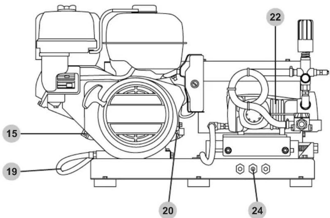
natural_image
Technical illustration of a mechanical component with a meshed circular feature and an arrow indicating direction (no text or symbols)natural_image
Technical line drawing of a connector with threaded ends and a hexagonal nut (no text or symbols)natural_image
Technical line drawing of a mechanical component with an arrow indicating assembly or transformation (no text or symbols present)
AVISOAV
PURGA DE BOMBA
natural_image
Line drawing of a fuel pump component with attached hoses and valve (no text or symbols)natural_image
Illustration of two hands holding a small object with an arrow pointing to it (no text or symbols present)natural_image
Simple black-and-white illustration of a rabbit and a turtle on a curved surface, with an arrow pointing left (no text or symbols)natural_image
Pure electrical circuit lines without any symbolsCERRADO
natural_image
Simple line drawing of a hand holding a tool with three arrows pointing outward (no text or symbols)natural_image
Two diagrams showing magnetic field lines around a positively charged conductor (labeled + and -), with no text or symbols beyond the plus/minus signs.
natural_image
Diagram of two LED-shaped components with positive and negative rotation arrows indicating magnetic polarity (no text or symbols)natural_image
Diagram of a mechanical component with a circular end connected to a shaft, showing bidirectional arrow (no text or symbols)natural_image
Diagram showing a connector being inserted into a socket (no text or symbols present)natural_image
Technical diagram of a mechanical component with a meshed circular base and threaded end (no text or symbols)natural_image
Simple line drawing of a valve with a curved arrow indicating rotation (no text or symbols)natural_image
Technical diagram of a valve assembly with a threaded cap and hexagonal base, showing upward force (no text or symbols)natural_image
Diagram of a mechanical component with arrows indicating motion or force direction (no text or symbols)natural_image
Diagram of a valve assembly showing a handle, nut, and bolt (no text or labels)natural_image
Technical line drawing of a mechanical assembly with rollers and a tank (no text or symbols)
natural_image
Technical line drawing of a mechanical assembly with no visible text or symbolsnatural_image
Diagram of a pulley system with two wheels and a belt drive (no text or labels)natural_image
Technical line drawing of a pulley system with two wheels and a belt drive (no text or symbols)natural_image
Technical line drawing of a mechanical housing or enclosure with mounting holes and internal components (no text or symbols)natural_image
Technical line drawing of a mechanical device with no visible text or symbolsTensiónAflojar
natural_image
Technical line drawing of a mechanical device with a gas jar connected to a valve (no text or symbols present)natural_image
Diagram of a mechanical device with a spray bottle and pump, showing no text or symbols- READ THIS MANUAL CAREFULLY BEFORE OPERATION
- SAVE THIS MANUAL FOR FUTURE REFERENCE
- SAVE THIS MANUAL FOR FUTURE USE
- CALIFORNIA PROPOSITION 65 WARNING
- POLYCYCLIC AROMATIC HYDROCARBON WARNING
- SAFETY INSTRUCTIONS | 4
- DISCLAIMERS | 6
- PERSONAL PROTECTIVE EQUIPMENT | 6
- UNPACKING | 6
- ASSEMBLY | 7
- COMPONENT LOCATION | 10
- CONNECTING HOSES | 14
- PURGING AIR FROM THE PUMP | 15
- NOZZLES | 16
- OPERATING CHECKLIST | 17
- STARTING THE ENGINE
- SHUTTING OFF THE ENGINE
- OPERATION TIPS
- TROUBLESHOOTING
- MAINTENANCE
- STORAGE AND TRANSPORTATION
- USING SIMPSON® PUMP GUARD
- WARRANTY
- READ THIS MANUAL BEFORE OPERATING
- ADDITIONAL INSTRUCTIONS
- HAZARD ALERT SYMBOLS
- UNSAFE PRACTICES
- SLIP / TRIP HAZARDS
- Sign examples
- KEEP OUT
- Barrier examples
- NOTICE
- DISCLAIMERS
- PERSONAL PROTECTIVE EQUIPMENT (PPE)
- UNPACKING
- Adding the Foot Kit
- IMPROPER ASSEMBLY
- Connecting to Battery Source (if applicable)
- BATTERY CONNECTIONS
- Note the following:
- Connecting to Fuel Source (if applicable)
- Storing the Nozzles
- Adding the Pump Breather Cap
- TWIN CYLINDER BELT DRIVE
- CONNECTING HOSES (not included)
- PUMP PURGING
- WARNING:
- INJECTION INJURY
- Nozzle Selection
- SPRAY DAMAGE
- Nozzle Installation
- OPERATING CHECKLIST
- Location
- TOXIC FUMES
- High Altitude Operation (Non-EFI models, only)
- ALTITUDE
- Operating Conditions
- CHILDREN AND UNTRAINED ADULTS
- ELECTRICAL SHOCK
- RISK OF BURSTING
- RISK OF EXPLOSION OR FIRE
- HOT SURFACES
- MOVING PARTS
- PRESSURE RATING
- Checking the Engine Oil
- HOT OIL
- LOW OIL SENSOR
- FILL ENGINE OIL BEFORE USE
- USE CORRECT ENGINE OIL
- Checking Fuel
- REFUELING
- OLD GASOLINE
- ALCOHOL BLENDS
- GASOLINE ADDITIVES
- GASOLINE STORAGE
- DO NOT OVERFILL FUEL TANK
- PUMP DAMAGE
- RAPID RETRACTION
- Terms
- Preparation
- Pressure Washing
- Adjusting Surface Pressure
- Adjusting Unloader Hand Control Knob to Adjust Pressure
- HIGH PRESSURE
- RISK OF BURNING
- RISK OF FIRE
- MODIFICATION INJURY
- Cleaning the Pressure Washer
- CLEANING
- CHEMICAL CLEANERS
- Connections
- Nozzle Cleaning
- Water Inlet Filter
- Pump Maintenance
- How to Change the Pump Oil
- Pump Gearbox Maintenance (if equipped)
- How to Change the Pump Gearbox Oil
- Belt Maintenance (if applicable)
- Removing the belt guard
- Measuring the belt deflection
- Adjusting the pump tensioner
- Engine Maintenance
- Storing for Two Months or Less
- Storing for More Than Two Months
- Transportation
- COMMERCIAL LIMITED WARRANTY
- WARRANTY COVERAGE TERMS:
- THIS WARRANTY DOES NOT COVER:
- RESPONSIBILITY OF ORIGINAL PURCHASER (INITIAL USER):
- WHAT THE WARRANTY DOES NOT COVER:
- ENGINE AND EMISSIONS CONTROL SYSTEM:
- HIGH-PRESSURE PUMP (DEFECTS IN MATERIAL AND WORKMANSHIP):
- FRAME (DEFECTS IN MATERIAL AND WORKMANSHIP):
- ACCESSORIES (DEFECTS IN MATERIAL AND WORKMANSHIP):
- THIS PAGE WAS INTENTIONALLY LEFT BLANK
- SIMPSON®
- LAVEUR SOUS PRESSION
- GUIDE D'UTILISATION ET D'ENTRETIEN
- RISQUES DE GLISSEMENT ET DE TRÉBUTS
- AVISAVI
- ENTRAÎNEMENT PAR COURROIE
- À CYLINDRE UNIQUE
- TRANSMISSION PAR COURROIE À DEUX CYLINDRES
- PURGE DE LA POMPE
- LISTE DE CONTRÔLE DE FONCTIONNEMENT
- DÉPANNAGE
- PELIGROS DE RESBALÓN / TROPIEZO
- AVISOAV
- PURGA DE BOMBA
Brand : Simpson
Model : TM2810241E
Category : Pressure washer