
MainStream - Audio software MACKIE - Free user manual and instructions
Find the device manual for free MainStream MACKIE in PDF.


| Product Type | Portable PA System with Bluetooth |
| Dimensions (W x H x D) | 12.5 x 8.5 x 5.5 inches |
| Weight | 8.5 lbs (3.9 kg) |
| Power Supply | AC 100-240V, 50/60Hz, 30W |
| Battery Life | Up to 6 hours at 2/3 volume |
| Amplifier Power | 200W peak, 100W RMS |
| Frequency Response | 60Hz - 20kHz |
| Bluetooth Version | 5.0 with A2DP, AVRCP |
| Audio Inputs | 2x XLR/TRS combo, 1x 3.5mm stereo, 1x RCA |
| Audio Outputs | 1x XLR mix out, 1x headphone out |
| Master EQ | 2-band (Bass, Treble) |
| Built-in Effects | Reverb, Echo, Chorus |
| Speaker Configuration | 1x 8" woofer, 1x 1" tweeter |
| Coverage Angle | 90° horizontal x 60° vertical |
| Protection Features | Overvoltage, overcurrent, thermal shutdown |
| Care and Cleaning | Wipe with dry cloth; avoid moisture and extreme temperatures |
| Safety Warnings | Do not expose to rain or liquids; use grounded outlet |
| Spare Parts & Repairability | Contact Mackie support for authorized service |
| General Information | Designed for portable live sound reinforcement |
| Manufacturer | Mackie (LOUD Audio, LLC) |
Frequently Asked Questions - MainStream MACKIE
User questions about MainStream MACKIE
0 question about this device. Answer the ones you know or ask your own.
Ask a new question about this device
Download the instructions for your Audio software in PDF format for free! Find your manual MainStream - MACKIE and take your electronic device back in hand. On this page are published all the documents necessary for the use of your device. MainStream by MACKIE.
USER MANUAL MainStream MACKIE
natural_image
Symbolic icon of a running person inside a circle, no text or numbers presentMACKIEMATRIX
OWNER'S MANUAL V1.1.30

Table of Contents
Table of Contents 3
Chapter 1: Welcome......6
Introduction......6
Features 6
About This Guide 6
Chapter 2 : Mixer Setup ....7
Introduction......7
Applying Audio Sources to the Mixer 7
Mixer Setup....10
Manage Presets ....10
Reset Channel Name/Icons....13
Chapter 3 : Mixing....14
Introduction....14
Input Channels....15
Channel Faders and Input Meters....15
M-VOICE 15
M-FX....15
Solo 16
Mute 16
Sampler Channel 16
Sampler Channel Fader....16
M-VOICE 16
M-FX 16
Solo 16
Mute 16
Sample Pads....17
Output Level 17
Main Output Fader and Meters 17
Solo 17
Current Mix 18
Mix Effects 19
Stream Destination....19
Virtual Device Channel Routing....20
Menu 21
Chapter 4 : M-VOICE ...... 24
Introduction....24
Easy Control Mode 25
Channel Name....25
Control Mode 25
Information (i) 25
Input Meters 26
X 26
Expand/Contract 26
Output Meters 26
Output Gain 26
Presets....27
Parameter Setup - EQ (Easy) 28
Parameter Setup - Gate (Easy) 30
Parameter Setup - Compressor (Easy) 31
Parameter Setup - De-Esser (Easy) 32
Pro Control Mode 34
Channel Name....34
Control Mode 34
Information (i) 34
Input Meters 35
X 35
RTA 35
Expand/Contract 35
Output Meters 35
Output Gain 35
Parameter Setup - EQ (Pro) 36
EQ Gain, Frequency, Q [Bandwidth], and Shelf/Bell 36
RTA 40
Parameter Setup - Gate (Pro) 41
Parameter Setup - Compressor (Pro) 43
Parameter Setup - De-Esser (Pro) 45
Chapter 5: M-FX....47
Introduction......47
Atomizer Reverb 47
ChronoTronic Delay 48
Telephone 48
StreamFX Voice Changer 49
Chapter 6 : Samples....50
Introduction....50
Sampler Channel 50
M-VOICE 50
M-FX 50
Solo 50
Mute 50
Sample Pads....50
Play Sample 51
Bank Switching....51
Pad Customization 52
Pad Name....52
Pad Color 52
Pad Mode 52
Play Style....53
Sample File 53
Looping....54
Hot Key Assign....55
Chapter 7: Presets....56
Introduction......56
Factory Presets vs User Presets 56
DSP Presets....58
Appendix A : Service Information....62
Troubleshooting....62
Chapter 1: Welcome
Introduction
Hello everyone! This is the Mackie Matrix Owner's Manual (version 1.1.30).
This document contains detailed information about Mackie Matrix... we hope you like it!
Mackie Matrix software comes included with your MainStream interface, but it's much more than a companion app.
Matrix is a powerful live streaming mixer in software form, giving you total control over all the audio you need for your live stream.
Combine all your hardware sources, including HDMI, microphones and cameras.
Use dedicated software channels to bring in virtual sources like Discord, Spotify, game audio and more.
Balance levels, add processing and effects, then send the mix straight into OBS — all from a single window on your PC.
So there you have it. Again, we hope you like it. If you have any questions or comments about this Owner's Manual (or other Mackie documentation), please don't hesitate to contact us:
• 1-800-898-3211 (Monday through Friday, normal business hours, Pacific Time)
• www.mackie.com/support-contact
Features
• Fully featured streaming mixer software
- Hardware inputs for connected devices
- Separate inputs for MainStream HDMI game feed and mic or headset
- Six virtual inputs for Discord, Spotify, games and other software
- Four flexible outputs for sending mix to OBS, monitors and more
- Three banks of eight virtual pads for triggering samples and sound effects (24 total)
- M-Voice vocal processing on every channel with optional one-knob control
- M-FX effects on every channel with reverb, delay, telephone and more
• Available for Microsoft Windows computers
About This Guide
This guide is designed to be accessible, with subsections as complete as practical to minimize having to electronically leaf back and forth looking for the whole story. The entire manual does not need to be read to figure out how to use Mackie Matrix.
As the saying goes, “a picture tells a 1000 words”. With that thought in mind, we added quite a few illustrations, screenshots and other images throughout to accompany the text.

This icon marks information that is critically important or unique! For your own good, read and remember them.

There's an illustration of a microscope, so, of course, you're going to get more detailed information when you see this little guy. There are explanations of features and practical tips listed here.

It's a good idea to pay attention to text displayed next to a note icon, as this icon draws attention to certain features and functions relating to the usage of Mackie Matrix.
Chapter 2: Mixer Setup
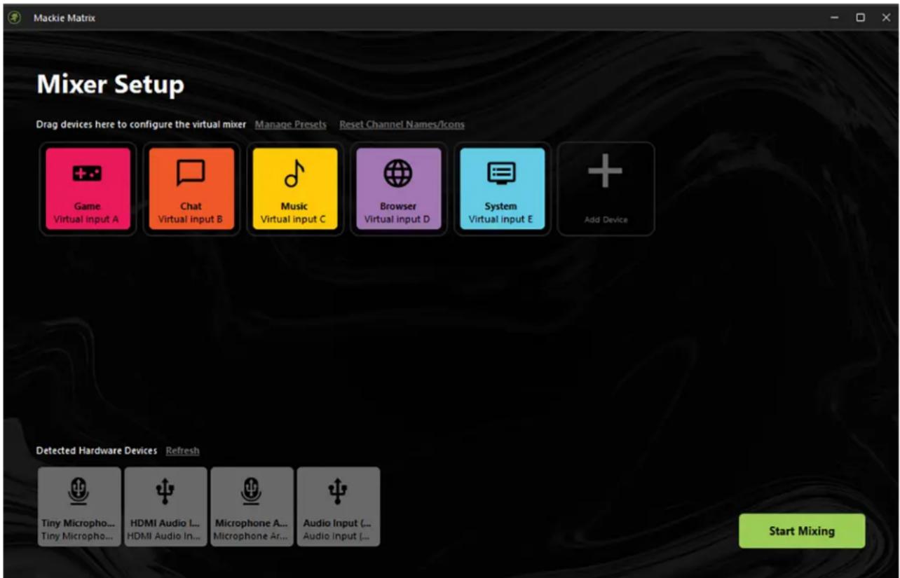

We love sharing so many Mackie apps for free as a "try before you buy" incentive. Unfortunately, while the Mackie Matrix app itself is free, it ONLY works when connected to a MainStream hardware device.
Introduction
The opening view of the Mackie Matrix middleware looks similar to what is displayed above. Wait, did you just say "middleware"? Yes, we sure did! If you are familiar with hardware and software, but could use familiarity with middleware, middleware is essentially a computer software program – Mackie Matrix in this case – that allows multiple non-OS programs (such as Discord ^® , Spotify ^® , or even a web browser, for some examples) to function and communicate with each other. These audio sources are then "mixed" – by you via Mackie Matrix – before they are sent to the stream.
Applying Audio Sources to the Mixer
The way to begin is by applying audio sources to Mackie Matrix. This is similar to connecting audio sources to a Mackie mixer.
Mackie Matrix does a good job at determining if something is connected, and if so, what it is. In the example above, there is a Microsoft Xbox ^® connected to the HDMI input jack, a microphone connected to one of the USB-C inputs, and a video camera to the other. These are the hardware devices.

Not all hardware has to be connected directly to MainStream in order for it to be recognized and utilized. In fact, if you have multiple cameras and mics, these may be connected to a USB hub that is connected to the computer. These should all be detected hardware devices. There could be a myriad of reasons why a hardware device will not be detected, but if that occurs, we suggest tapping 'Refresh'.
As mentioned previously, there is also audio from the virtual devices: Discord ^® , Spotify ^® , audio from a browser, etc. These are then connected together, mixed, and sent to the stream.
One big question is: why do we apply audio sources to the virtual mixer?
Let's begin by restating the fact that up to four hardware inputs may be added. This is in addition to whatever hardware is connected directly to MainStream. It helps in that multiple people may be connected to a livestream or podcast simultaneously via mics connected to a USB hub (with headphones connected the phones jacks on the mics)... and/or extra video cameras for multiple angles and views. These are sources that will be added to the virtual mixer of Mackie Matrix.
Another big question is: how do we apply audio sources to the virtual mixer?!
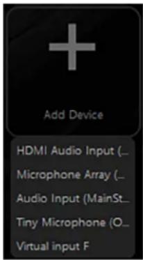
Adding devices – hardware and virtual – is quite simple. At the end of the top row is a big “+” sign with the text, “Add Device”. Notice in the screenshot to the right, we have clicked “Add Device”. The top four selections is the hardware; these are listed horizontally on the bottom row as seen on the previous page. At the bottom of the list will be an option to add another virtual input. Move the mouse to the selection and click to make your choice.
Now, in addition to "Add[ing] Device", the hardware devices (again, located on the bottom row) may be added to the top row simply by using the mouse. Click-and-hold the audio device and drag it to the top row.
Once an audio device has been “moved” to the virtual mixer, it will be darkened (on the bottom row) to show that it is no longer an option to add.
We would like to remind you that in addition to four hardware inputs, up to six virtual inputs may be added. These are independent audio sources that live on whatever programs and apps
are on the computer, such as Discord ^® , Spotify ^® , a web browser, a video game, and more. These are then connected together – with the hardware – mixed, and sent to the stream. We discussed how to add virtual inputs to the mixer above. However, as seen on the previous page, most of the “typical” virtual inputs have already been added: Game, Chat, Music, Browser, and System.
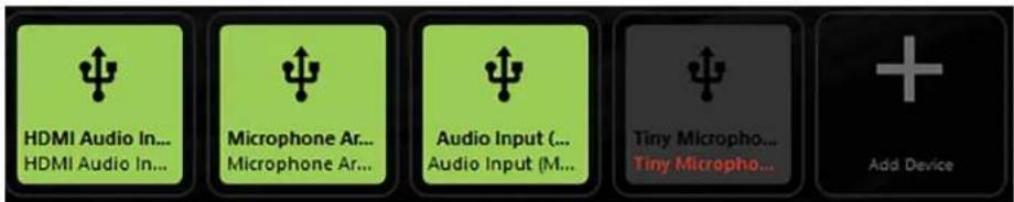
Once the inputs have been added, the screen might look a little like something as displayed below:


If you would prefer a device at the beginning of the row or between other inputs, then drag it there!
As seen below, if a hardware device has been removed from MainStream and/or a USB connection, it will be greyed out and the text will turn red, indicating that it needs to be re-attached.

If there are any audio sources in the virtual mixer (top row) that are unnecessary, they may be deleted by hovering over it and clicking the "x" in the upper-right corner, as seen to the left. These virtual devices may also be edited using the pencil icon located in the upper-left corner. More info below regarding editing virtual inputs.
Editing Inputs
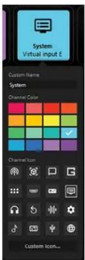
Mentioned previously – and seen to the left – is the fact that you are able to edit inputs.
This includes a custom name, the channel color, and channel icon.
Changing the name is as simple as placing the cursor at the end of the name, deleting the preceding alphanumeric keys, then re-writing with your own fancy name!

The modern English alphabet consists of 26 letters. I was able to enter this alphabet FOUR times over without 'hitting any walls'. Granted, only 14 characters show up at a time, so best to use something shorter (and thus, readable).
The current color of the virtual input has a check mark. This may be updated to a color that suits you more.
Use the mouse to hover over the color, then click to select.
Icons are similar to the colors. Instead of a check mark, though, the currently selected icon is boxed in by a thin white line.
Use the mouse to hover over an icon that better suits you, then click to select.

There is an option to upload your own personal icon. Perhaps you have a gamer tag with your own personal ID. Let's use that instead of some boring 'ol icon, right?! At the bottom of the column is an option to add "Custom Icons...". After selecting it, you will be required to find the personal icon and select it from the computer.
Mixer Setup
In the upper-left corner of Mackie Matrix is "Mixer Setup". We have already added hardware devices and virtual inputs to the mixer, as well as edited them to your liking. Let's take a look at what else may be accomplished in this Mixer Setup view. There are two choices: Manage Presets and Reset Channel Names/Icons.
Manage Presets

Presets save settings and parameters and may be recalled as needed. For example, multiple gamers may use the same equipment, but they would likely have different fader and EQ settings. These may be saved as presets and recalled as needed.

The fader, EQ, and other parameters are set when on the mixer side of things. Since we're still on the setup screen, we'll continue with it. Additional information about the mixer side, setting the fader, EQ, and other parameters may be found on pages 14-23.
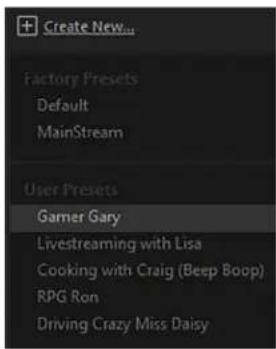
There are two factory presets (Default and MainStream), as well as a spot for user presets. The number of user presets available is limited only by the available space on the computer... so basically unlimited. Presets are generally set ahead of time, not as a livestream or other event is taking place.


Before moving to the right side of the screen, there is one very important section to check first. In the upper-left corner of the mixer is “+ Create New...”. This is how user presets are created.
After clicking "+ Create New...", you will be asked to name the preset (with the default being 'User Preset 1'). See image to the left. Go ahead and create (and rename) some presets. If you're feeling up to it, change some parameter settings in addition to the hardware and virtual audio inputs. We'll wait...
As you can see in the image to the right, five user presets have been created. Some are gamers and some are livestreamers, but all have different needs, whether in the hardware and virtual audio department and/or in the parameters section.
Now that we have discussed creating user presets, it is time to swing over to the right side of Mackie Matrix to chat about the other preset selections and what they do. In order to begin, tap a preset so it is highlighted. Let's take a look at each of the choices from top to bottom, starting with 'Recall'.
Recall - Selecting recall... well, it recalls presets! Upon recall, all appropriate parameters change to match the stored preset. After tapping recall, you'll hear the changes immediately and notice the changes to the parameters, as well.

When a preset is recalled, all currently set parameters will be deleted (with no undo), so a confirmation dialog helps prevent accidents. This includes recalling factory presets and user presets.
Factory presets may only be recalled. All other selections will be displayed, but they aren't selectable.

Since we're talking about factory presets, let's take a quick look at the two to see what they do when recalled. Then we'll return to the remaining preset choices.
Default – Recalling 'Default' will result in all added audio devices (hardware and virtual) being removed from the 'Virtual Mixer' and placed back in 'Detected Hardware Devices'. The original five virtual inputs remain in the virtual mixer (as seen on page 8). However, if they had been renamed, colored, and/or given a new icon, those will also revert back to their default state.
Of course, all fader levels, EQ settings, and other parameters will also be set back to their default states. Recalling the default preset is essentially the same as zeroing out a board.
MainStream – Recalling 'MainStream' will result in exactly the same as above save for one exception. The audio input from the MainStream will remain on the 'Virtual Mixer' at the beginning of the top row, before the virtual inputs.

Replace - Replace stores the current state of the processing over the currently selected preset. Be careful NOT to do this... or do it only if so intended.

When a preset is replaced, all currently set parameters will be deleted (with no undo), so a confirmation dialog helps prevent accidents.
Rename - When rename is chosen, use the keyboard to rename the currently selected preset.
Delete - The delete button deletes the currently selected preset.

When a preset is deleted, all currently set parameters will be deleted (with no undo), so a confirmation dialog helps prevent accidents.
Export Selected... - When a single USER preset is selected, you are granted the option of exporting it to the computer's hard drive, an attached thumb drive, portable disk, or other. Just remember where it was exported!
If the file already exists in the location that you're trying to export it to, you will be prompted to answer the following questions:
"Is Darth Vader my father?"
"What is the airspeed velocity of an unladen swallow?"
"Mrs. Robinson, you are trying to seduce me, aren't you?" and most importantly...
"Do you want to overwrite it?" "Do or do not, there is no try." The choice is yours.
Export All... – Regardless of what preset is selected, you are granted the option of exporting ALL of them (simultaneously) to the computer's hard drive, an attached thumb drive, portable disk, or other. Just remember where they were exported!
If any of the files already exist in the location that you're trying to export them to, you will be prompted to answer the same questions as listed above.
Import - Importing presets is simple. After clicking on the 'Import' button, select the desired presets. They will be added in the order selected. In other words, if the presets were saved (and exported) as 'User Preset 1', 'User Preset 2', 'User Preset 3', 'User Preset 4', etc., they may be re-ordered to your specifications. It is not based on alpha-numeric order unless you choose it to be.

If all possible presets have been imported, then the imported button darkens and it is no longer available for selection.
And that wraps up the 'Manage Presets' portion of the manual. If you're not an expert yet, you will be soon. Practice doesn't make perfect... but it does make better.
Just to the right of 'Manage Presets' is 'Reset Channel Name/Icons'. This will be a breeze. Let's take a look!
Reset Channel Name/Icons

This does exactly what it states. It resets all channel names and icons to their default settings. Additionally, all devices on the virtual mixer will be the same light-green color. In fact, the screenshot displayed on page 8 is also shown below, but after 'Reset Channel Name/Icons' was clicked.
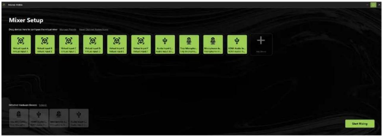
See how easy it is to 'Reset Channel Name/Icons'?!
So guess what?
That's right, at this point, there's nothing else to do except... START MIXING! The button is located in the lower-right corner of the screen. Go ahead and click it.
Chapter 3: Mixing

Introduction
As noted on the bottom of the previous page, we already took care of the mixer setup, so "...at this point, there's nothing else to do except... START MIXING!" The screenshot displayed above is something similar to what you may see, as well.
The great news is that it's pretty much "set it and forget it." Once all of the levels, EQ, and other parameters are set, then gaming/livestreaming/podcasting is a go!
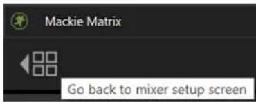
Let's take a look around the mixer at the different selections and decipher their not-so-hidden meanings. We'll start in the upper-left corner. Just underneath "Mackie Matrix" is a gray left-facing arrow with four boxes next to it. Selecting this simply returns you to the previous screen, the mixer setup.

Something really great about Mackie Matrix is that you're able to hover over a multitude of features. When hovering, a popover will be displayed indicating what the feature will do when selected, as seen in the screenshot above-left. This is only a default, though. It may be turned off via Menu > Settings > Show hints when hovering. More information may be found on page 23.
Input Channels
Regardless of the number of hardware and virtual audio inputs that have been added, each input channel strip contains the following features:

Channel Faders and Input Meters
The channel faders adjust the level of each channel going to the selected output(s). The volume levels range from off (silent) to max (full volume).
As you can see in the popover to the left, clicking the left button will set the fader level, either by click-and-drag or left-click in the position you want the fader set. Clicking the right button on the mouse will set the fader to its default.
Notice also that the selected channel fader "glows". All other channel faders will remain dimmed.
The stereo input meters display the relative level of each input channel. They should remain green with the occasional bump into the yellow zone. Turn down the volume if the input meter remains consistently yellow. If the input is too high [overloading], a clip indicator at the top of the meter will illuminate red. If clipping occurs, reduce the volume of the source device.
At the bottom of each channel strip are two icons that may be selected. On the bottom-left is an icon of a pair of headphones. For all intents and purposes, this is how to solo a channel. On the bottom-right is an icon of a speaker. This is how to mute a channel. More info on soloing and muting coming up soon.

M-VOICE
Above the channel faders and input meters is the M-VOICE popover. There is one for every input. Because it's a popover with a significant number of features, we will take a closer look at it in Chapter 4, pages 24-46.

M-FX
Above the channel faders and input meters is the M-FX popover. There is one for every input. Because it's a popover with a significant number of features, we will take a closer look at it in Chapter 5, pages 47-49.
SOLO

Solo offers the opportunity to audition channel(s) [input channel strips] before they are added to the mix. Whenever a channel's solo is engaged, only the soloed channel(s) may be heard. It illuminates amber when engaged as seen to the right.
MUTE

Mute essentially "turns off" the signal on the selected input(s). It illuminates red when engaged as seen to the right. Additionally, notice how the fader of a muted channel turns from green to red.

Sampler Channel

The sampler channel strip contains the following:
Sampler Channel Fader
The sampler channel fader adjusts the level of the samples going to the output. The volume level ranges from off (silent) to max (full volume). It is a global control, affecting the level of all samples.
M-VOICE
Above the sampler fader and input meters is the M-VOICE popover. There is one for every input, including the sampler. Because it's a popover with a significant number of features, we will take a closer look at it in Chapter 4, pages 24-46.
M-FX
Above the sampler fader and input meters is the M-FX popover. There is one for every input, including the sampler. Because it's a popover with a significant number of features, we will take a closer look at it in Chapter 5, pages 47-49.
SOLO
Solo offers the opportunity to audition the sampler channel before it is added to the mix. Whenever a channel's solo is engaged, only the soloed channel(s) may be heard. It illuminates amber when engaged.
MUTE
Mute essentially "turns off" the signal on the sampler channel. It illuminates red when engaged. Additionally, the fader turns from green to red.
Sample Pads

Clicking on one (or more) of the eight samples results in playback of the saved sample. When clicked, the sample will play. Additionally, a "timer" will be displayed for the duration of the playback. If no sample is assigned, it will remain grayed out, as seen to the left.
Displayed below the eight samples (and directly to the right of the sampler solo and mute) is a letter book marked by two outward-facing arrows. Clicking on the arrows switches between the sample banks. There are four banks (A-D) with eight spots for samples in each bank... that's a total of 32 possible samples that may be added!
The samples, playback mode, colors and more may be changed and updated. Because it's a popover with a significant number of features, we will take a closer look at it in Chapter 6, pages 50–55.
Before discussing the M-VOICE, M-FX, and sample pads in further detail, let's first look at the top row of Matrix to see what it can do for you! This was already shown a couple of pages back, but here is another look, but just of the top strip. We will start in the middle with the output level followed by the left-side features, and ending with the features on the right-hand side of the screen.

Output Level
Like the input channel strips, the horizontally-lined master output channel strip also contains a fader and solo button. However, unlike the input channel strips, the output master channel strip is linked to the outputs, not the inputs. Additionally, there is no mute.

Main Output Fader and Meters
The main fader adjusts the level of the output, while the output meter displays the output signal level, presented in stereo L/R.
The meters should remain green with the occasional bump into the yellow zone. If there is too much yellow (or any red clipping), lower the main fader until it's gone and check the input channels, as well.
SOLO

The output solo is linked to whatever destination has been selected in the (monitor's) stream destination. It allows you to switch back-and-forth between your (monitor) settings and the viewers' (stream) settings without the different fader levels affecting the actual stream. This gives you an auditory glimpse into their world and to make any necessary adjustments, if necessary.
The current mix and stream destination are discussed further over the next couple of pages. As seen in the screenshot above, the output solo icon illuminates amber when engaged.
Current Mix
We just checked out the output level fader and meters which eats up almost the entire top row.
However, there are a few features in the upper-left and upper-right corners of the screen, as well.
In the upper-left is a section called 'Current Mix' which we will visit... second.

First, though, we want to send a quick reminder about something we saw several pages ago:
Just underneath "Mackie Matrix" is a gray left-facing arrow with four boxes next to it.
Selecting this simply returns you to the previous screen, the mixer setup.
On to the current mix selection.
Utilizing the pull-down menu, select one of four individual mixes to view and edit.

As seen below, the four selections to choose from include "Stream" (default), "Monitor", "Virtual Mix 1", and "Virtual Mix 2".
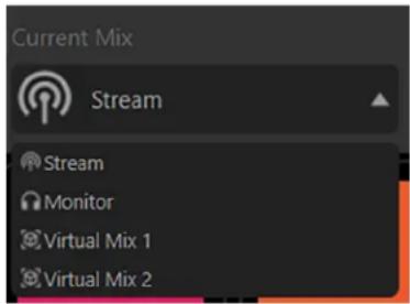
Stream is the current mix that will be utilized the most as it is the mix that is sent to the stream, and ultimately, the audience. However, the other three mixes are important in order to dial in the desired levels to monitor the mix, as well as the two virtual mixes. Go ahead and use the pull-down menu to select "Monitor".

natural_image
Pure electrical circuit lines without any symbolsINPUT 1 INPUT 2 (LINKED)
As seen in the screenshot to the left, it will look roughly the same as the "Stream" mix, with just one difference: the ability to link channels. By default, all inputs are not linked.
For this example, we will just call them "INPUT 1" and "INPUT 2". Note that it will look similar to this regardless of whether it's connected hardware and/or virtual inputs.
Input 1 is unlinked. There are two ways to tell. First, there are linked chains with a diagonal line through it; this has been grayed out, and second, there seems to be a random open green rectangle floating above the gray fader. These two things are indicators that changes may be made!
The “random open green rectangles” are not so random. They display the fader level of the stream mix, regardless of the selected current mix. In order to set the fader level of the monitor output, click-and-hold the mouse button over the gray fader, move it up and down to the desired setting, then release.
To the right of input 1 is input 2. Notice the differences. It is linked, no line through it, plus the icon illuminates a pretty cyan color. Also of note is the "random open green rectangle" which – if you look closely enough – is actually surrounding the gray fader. The reason why is because they are linked. Moving the fader in the stream mix will also move it in the monitor mix. Moving faders in the stream mix will only move faders in the monitor mix when they are linked! Unlinked = separate faders, linked = connected!
The virtual mixes work exactly like the monitor mix, except the faders of the virtual channels raise/lower the volume of the virtual channels. The “random open green rectangles” indicate the fader levels of the stream mix, and the gray faders may be used to raise/lower the volume of the virtual channels.
Once mixes have been created, simply return to the “Stream” mix and leave it there. After all, the fader levels have been adjusted and there is no reason to return unless the volume of one of the mixes needs to be updated (and/or faders linked).
Mix Effects
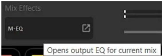
Earlier we mentioned that above all channel faders and input meters (including the sampler channel) lies an M-VOICE popover. Guess what? There is an M-EQ for the OUTPUT, as well! Clicking on the M-EQ output (located directly to the left of the output fader and meters) opens the output EQ for the current mix, as displayed below. Because it's a popover with a significant number of features, we will take a closer look at it in Chapter 4, pages 24-46.
Stream Destination
With the upper-left and middle sides discussed, let's swing over to the upper-right side of Mackie Matrix. Here you will see 'Stream Destination', 'Virtual Device Channel Routing', and the 'Menu'. Let's visit them in that order.
Utilizing the pull-down menu, select an output hardware device to listen to the monitor mix.

As seen below, the four selections to choose from include "No Output", "Stream Mix - Mackie Matrix", "Monitor Mix - Mackie Matrix", "Virtual Mix 1 - Mackie Matrix", "Virtual Mix 2 - Mackie Matrix", "Audio Output - (2- MainStream)", and "Speakers (Realtek(R) Audio)".

For all intents and purposes, there is no need to worry about the top and bottom choices, "No Output" and "Speakers (Realtek(R) Audio)".

For the most part, these line up 1-to-1 with the current mix. In other words, it looks a little something like this:
| CURRENT MIX STREAM DESTINATION | |
| Stream Stream Mix – Mackie Matrix | |
| Monitor Monitor Mix – Mackie Matrix | |
| Virtual Mix 1 Virtual Mix 1 – Mackie Matrix | |
| Virtual Mix 2 Virtual Mix 2 – Mackie Matrix |
This is a simple "set it and forget it". Once the current mix and monitor destinations are lined up how you want, all you need to do is open the current mix to make any changes. If you open the monitor destination and change it, you'll end up changing the destination of the current mix. We do not want that!
That said, one possibility could be selecting "Monitor" as the current mix, but instead of leaving it at its default of "Monitor Mix - Mackie Matrix" as the stream destination, choose "Audio Output - (2- MainStream)" instead.
What this accomplishes is that the (monitor) audio output is passed through MainStream.
Virtual Device Channel Routing
As seen by hovering the mouse over the icon in the screenshot below, this is the place to setup virtual device channel routing. The hardware is set up automatically as a hardware device. However, the virtual channels need to be assigned in order for Mackie Matrix to read and identify the channels and route them appropriately.

← Settings
App volume and device preferences
Adjust the master volume to change all sounds. You can adjust volume for specific apps and system sounds as a percentage of the master volume.

Output
Audio Output (2- M...
Input
Tiny Microphone (O...
As seen to the left, once the icon is clicked, a new Windows ^® screen will appear, requesting that the virtual inputs be assigned. Notice how they all start at "Default".

In Windows 11, each app must be clicked for a dropdown to appear that shows I/O routing.
Here is how to assign virtual inputs. First, make sure that the program to assign is running. For example, load up Spotify ^® , YouTube ^® , Bandcamp ^® , or other music player and play an album.
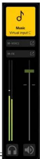
With audio playing, minimize the screen so the app volume and device preferences screen appears again. Since we left the virtual inputs in their default state, we know that "Music" is on virtual input C.


As stated above, we left "Music" on its default virtual input C. However, you may have rearranged the virtual channels and "Music" could very well be located on a different virtual channel. Choose the correct one. Furthermore, the music
could be routed to any other virtual channel ("Game", "Chat", "Browser", etc.) and the meters will show up there. This is all fine, of course, but if done, it may be difficult to determine if the actual virtual channel is what it states that it is.
Continuing on, utilizing the pull-down menu on any of the available Mackie Matrix OUTPUTs, select "C - Channel Mackie Matrix (2- MainStream)". If set correctly, then the app volume and device preferences will look similar to what's displayed below.


Additionally, notice the bouncing meters on virtual input C once the Windows screen is cleared and you're back to mixing. Nice job! Now do this for the remaining virtual inputs.

The input does not need to be set – leave at 'Default' – since whatever is "attached" to the virtual input IS the input itself! It is just being output to the virtual input where it may be mixed with the connected hardware (and other virtual inputs) before being sent out to MainStream.
Menu
In the upper-right corner of Mackie Matrix are three horizontal lines; this is affectionately referred to as a 'hamburger button'. Click on it to open the menu bar. The list below describes all of the goodies as seen below-left.


- System Audio – Do you recall the virtual device channel routing that we just discussed? Clicking on that icon (to the left of the hamburger icon) takes you directly there. However, if you enjoy taking extra steps to achieve the same result, then by all means open the menu bar and select 'System Audio' from there. Read more about 'System Audio' and 'Virtual Device Channel Routing' on the previous page.
- Product Manuals – Several resources – including support documentation, videos and more – have been created for Mackie Matrix. Click here to check out the product manuals!
- Technical Support – So you need someone to talk to and your psychiatrist doesn't know the first thing about Mackie Matrix? We've got your back... click here to contact Tech Support!
- Privacy Policy – Fancy yourself doing some investigative reading (or need some material to help you sleep)? Click on 'Privacy Policy' and read away.
- Settings – When settings is first clicked on, it will look something like what you see below-left. Let's discuss each of the settings, what they do and how they benefit you.
- Mackie Matrix Folder Location – This is the place to determine where to backup and restore the system. Feel free to choose the location/folder of your choice – after all, it is YOUR computer – but the default is 'C:/Users/"your_name"/Documents/Mackie Matrix'.


- System Backup... / System Restore... – Here is where to export (System Backup...) and import (System Restore...) full system backups. Occasional full system backups are highly suggested.
Once the location/folder has been determined (via Mackie Matrix Folder Location), the Mackie Matrix system may be saved for future retrieval by clicking on 'System Backup...'. Name the file what you want, then click on 'Save'.

Doing a full system restore is just as easy as saving one is! Mackie Matrix system may be loaded (i.e. restored) by clicking on 'System Restore...'. Select the file what you want, then click on 'Open'.


If some of these screenshots look like they have been redacted, it's because they have... sort of. Unfortunately, we can't let you see what other projects we're currently working on! Additional new products coming soon, woo-hoo!
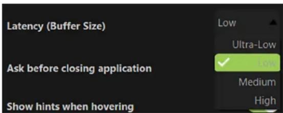
- Latency (Buffer Size) – The buffer size determines the amount of latency or delay for audio to pass from the audio interface through the computer to headphones and speakers. Use it to configure the amount of memory used to buffer the audio for processing, playback and recording.
Generally speaking, to get the highest performance out of your system, you will need to configure the driver's buffers. Lower latency settings will tax the system resources at a higher rate than higher latency settings. There are four buffer sizes to choose from as seen in the screenshot below.
In general, you should always experiment with the available buffer sizes to find the lowest buffer size that the machine and project can comfortably work with.
Mackie Matrix allows for latency buffer sizes as low as "Ultra-Low". However, using a buffer size this low requires a very fast computer with a large amount of RAM and fast hard disk and system bus speeds.
Finding the right settings for your machine is often an effort of experimentation, trying each setting and seeing if your computer continues to handle audio without drop-outs or distortion. If you are experiencing drop-outs or distortion, try raising the buffer size to the next available setting.

Mackie Matrix

Are you sure you want to close the application?
Any ongoing streams will be interrupted.
Yes
No
- Ask before closing application – A safety feature of Mackie Matrix is that it will not close without first firing a warning shot (as seen to the left). However, if you feel like livin' on the edge, turn this function off by making sure the switch is disengaged (switch left). When on [default], this switch is green. It is grayed out when turned off.
- Show hints when hovering – Something really great about Mackie Matrix is that you're able to hover over a multitude of features. When hovering, a popover will be displayed indicating what the feature will do when selected. This is only a default, though. Turn this function off by making sure the switch is disengaged (switch left). When on [default], this switch is green. It is grayed out when turned off.
- Software Version – At the bottom of the menu is the software version. There is nothing to click here, yet it could be useful to Tech Support. It displays information about the Mackie Matrix version that is currently installed. For the most part, this information is useless mumbo jumbo. There is no need to pay attention to this unless requested by Technical Support.
Chapter 4: M-VOICE

Introduction

Mentioned on pages 15-16 is the description on how to open a channel's M-VOICE. As seen to the left, the M-VOICE of each hardware and virtual input may be accessed by a simple mouse-click on that input.
The M-VOICE area contains four – count 'em, FOUR!! – different features that may be set to your preference. These include EQ, Noise Gate, Compressor, and De-Esser! Not only that, but you can choose between "Easy" mode and "Pro" mode, the former shown above; it's the green text located in the upper-left corner of the screen. We will go through everything soon enough, but for starters, we'll begin with the "Easy" control mode.
Easy Control Mode
Displayed below is the "Easy" control mode. Let's take a look around!

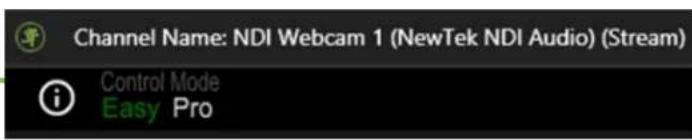
Channel Name: NDI Webcam 1 (Stream) – There is nothing to click, turn, push, or anything else here. Yet, it remains quite important! Simply put, it displays which input's 'M-VOICE' button was clicked and what the Current Mix is set to. In this particular example, this is the "NDI Webcam 1" input and the Current Mix is set to "Stream".
Control Mode – On the previous page, we mentioned that there is an "Easy" Control Mode and a "Pro" Control Mode.
The currently selected Control Mode will be in green text, while the other selection will be in white text. As stated previously – and confirmed via the screens displayed here – we are currently in "Easy" Control Mode.
Information (i) - Click on the encircled “(i)” to reveal a popover similar to what's displayed below.
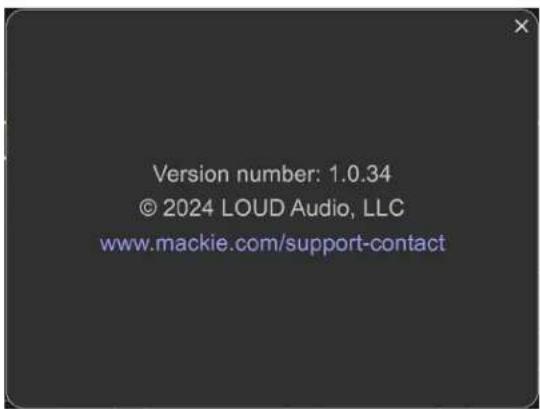
This is detailed version information about the Mackie Matrix app. For the most part, this information is useless mumbo jumbo. There is no need to go here unless requested by Technical Support.
Click on the "X" in the upper-right corner to exit the screen.

Input Meters - The stereo input meters display the relative level of each input channel. They should remain green with the occasional bump into the yellow zone. Turn down the volume if the input meter remains consistently yellow. If the input is too high [overloading], a clip indicator at the top of the meter will illuminate red. If clipping occurs, reduce the volume.

This only displays the input meter level. The input may be lowered by either (1) lowering the source of the input and/or (2) lowering the input fader level (located on the main mixing screen).
Ok friends, let's swing on over to the upper-right side of the screen now!
X - Clicking on the "X" will close out the Control Mode window and return you to the mixer view.

This is the only way to access the mixer view. The Control Mode screen cannot be “moved out of the way” to make changes to the mixer view.

natural_image
Abstract black background with diagonal white stripes (no text or symbols)Expand/Contract - The Control Mode window may be scaled for a larger (or smaller) look, how 'bout them apples?! In the lower-right corner of the screen are several diagonal lines. These may be clicked (and held) while moving the mouse down and out/right (screen expands) or up and in/left (screen shrinks).

Again, regardless of screen size, the Control Mode screen cannot be "moved out of the way" to make changes to the mixer view.
Output Meters - The output meters display the output signal level, presented in stereo L/R. The meters should remain green with the occasional bump into the yellow zone.
If there is too much yellow (or any red clipping), lower the output gain (more below) until it's gone and check the input channels, as well.
Output Gain - Located below the output meters is the output gain control. Use it to raise/lower the output gain by up to ± 12 dB. This may be changed one of two ways: (1) hovering inside of the output gain circle, then rotating the mouse wheel to change the output gain; increments will be ± 1 dB, or (2) left (or right)-click (and hold) the mouse inside of the output gain circle while also moving the mouse up (increases gain) or down (decreases gain) by ± 0.xx for even more detailed settings!
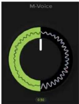
There is still one thing we haven't discussed... yet it's the thing that takes up the most space on the Control Mode screen. Yes, we're talking about the M-VOICE knob!

There is a screenshot of the entire EASY Control Mode screen two pages ago. The included dynamics – EQ, Gate, Compressor, and De-esser – are processed and mixed. Raising or lowering this knob affects that dynamic audio processing. This knob sets the total amount of the mixed dynamics for this input/channel (with the parameters of the dynamics set up by... you!)
The range is from 0 (off) to 1 (max).
This may be changed in one of three ways:
(1) Hovering inside of the M-VOICE circle, then rotating the mouse wheel to change the amount of dynamics; these increments will be ±0.04 dB.
(2) Left (or right)-click (and hold) the mouse inside of the M-VOICE circle while also moving the mouse up (increases dynamics level) or down (decreases dynamics level) by ±0.01 for even more detailed settings!
(3) Click the mouse on the number below the knob to enter the amount of dynamics you prefer. Note that anything ≥±0.005 will be rounded up, while anything ≤±0.004 will be rounded down.
pie
M-Voice | Category | Value | |---|---| | Green Segment | 0.50 | | Black Segment | 0.50 |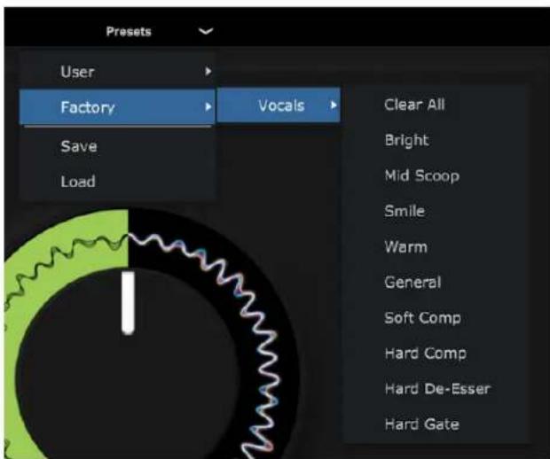
Presets – Presets save parameters and may be recalled as needed. Mackie Matrix comes with a library of factory presets. There are also user presets. These may be created for each preset type.
The presets pull-down is located at the top-center of the display. Mouse-click on it to open the pull-down menu that presents the list of options.
Click-and-hold on a preset - Factory to start with - so it is highlighted then release to select. Once released, all appropriate parameters change to match the stored preset. You'll hear the changes immediately and should notice visible changes to the settings, as well. From here, all that's required is to rotate the giant knob!

We highly suggest that beginners start with this route until fully comfortable with how to make changes to the parameters.
The following pages explain in detail how to set up your own personal parameters for each dynamic within the Easy Control Mode section.
An entire chapter is dedicated to presets. This includes detailed instructions and multiple screenshots every step of the way. Please check it out on pages 56-61.
Parameter Setup - EQ (Easy)
As mentioned above, the parameters need to be set in order for the M-VOICE knob to add dynamics.
Directly to the left of the M-VOICE knob is an icon containing three horizontal fader sliders.
Mouse-click on this icon to reveal something similar to what may be seen below:
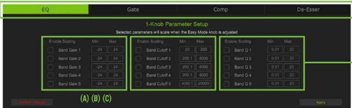
The first thing to notice is the top of the screen. Clicking on any of these tabs – EQ [default], Gate, Comp, or De-Esser – will open that particular dynamic's parameters. Additionally, the selected dynamic's tab will be highlighted green. As seen above, the default EQ screen is displayed initially. Go ahead and click through the other dynamic's tabs to get a quick look at them, then head back to EQ when good and ready!
The fun begins here! As mentioned at the top of the chapter, the equalizer area accesses all EQ-related parameters such as 5-band EQ for the selected channel (including (A) gain, (B) frequency/cutoff, and (C) Q/width). As seen above, all five bands provide up to 24 dB of boost or cut. While the entire frequency range is 20 Hz to 20 kHz, each EQ band has its own range. Lastly, the Q/width ranges from 0.01 to 20 for all five bands.

It was stated previously, but... with too much EQ, you can really upset things. We've designed a lot of boost and cut into each equalizer circuit because we know that everyone will occasionally need that. But if you max the EQ on every channel, you'll get mix mush. Equalize subtly and use the cut, as well as the boost. If you find yourself repeatedly using a lot of boost or cut, consider altering the sound source, such as placing a mic
differently, trying a different kind of mic, a different host, or gargling.
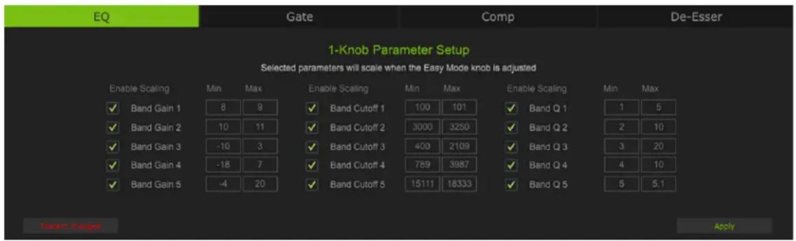
To get started, simply mouse click in one of the min/max boxes and enter the minimum and maximum settings preferred for each band. Continue to do so for each parameter. On the far left-hand side of each green box on the previous page are several small gray boxes. [These boxes are also displayed below.]. EQ parameters that you would like added to the final mix need to be engaged, as well. To do so, mouse click on the box to give it a green check mark. We prefer full EQ and checked all boxes (as well as added some min/max settings), see below:

Although the Q control does adjust the bandwidth of a filter, the Q value itself is dimensionless; it has no unit of measurement. Some equalizers use the fractional bandwidth of the filter, measured in octaves, to express this parameter. The two parameters are inversely related; a high Q value corresponds to a small fractional bandwidth. The following table lists some equivalent Q and fractional bandwidth values.
| Q BW (oct) Q BW (oct) | |||
| 0.7 2 2.871 1/2 | |||
| 1.414 1 4.318 1/3 | |||
| 2.145 2/3 15 1/10 |
The last thing to do here is to click on "Apply" in the lower-right corner of the screen so the settings are saved and, well... applied! Or click on "Discard changes" in the lower-left corner of the screen to exit and return to the main Control Mode screen.
| Parameter Low Value Limit High Value Limit | ||
| Gain [Bands 1-5] -24 dB | +24 dB | |
| Frequency / Cutoff [Band 1] | 20 Hz | 200 Hz |
| Frequency / Cutoff [Band 2] | 200.1 Hz 4,000 Hz | |
| Frequency / Cutoff [Band 3] | 200.1 Hz 4,000 Hz | |
| Frequency / Cutoff [Band 4] | 200.1 Hz 4,000 Hz | |
| Frequency / Cutoff [Band 5] | 4000.1 Hz | 20,000 Hz |
| Q (Bandwidth) [Bands 1-5] | 0.01 | 20 |
Parameter Setup - Gate (Easy)
Gates are typically used to reduce leakage from open microphones. Signals below the threshold level are muted, while signals above the threshold get to pass through. The range control changes the rule slightly. Signals below the threshold are attenuated by the amount of the range setting, while signals above the threshold get to pass through.
The operation of the gate is further modified by the hold control. Once the gate has opened, the hold time begins. The hold timer resets any time the input signal crosses the threshold again, as long as it remains above the threshold. After the hold time passes, the gain falls. The range control allows the gate to remain partly open, even if the input is below the threshold.

Hold — Hold sets a fixed time that the gate remains open once the signal drops below the threshold setting. During the hold time, the gain is held constant. The range of the hold time varies from 1 ms to 1000 ms.
Range — Range determines how far the gain drops once the signal is below threshold. Setting the range control to something in the -20 to -30 dB range allows some amount of signal leakage when the gate is closed, which may make its action more subtle (less abrupt) and therefore less noticeable. The range of the gated signal varies from -60 dB to 0 dB.
Threshold — Threshold determines the level at which the gate acts on the incoming signal. The range of the threshold setting varies from -60 dB to 0 dB.
Like the EQ tab, simply mouse click in one of the min/max boxes and enter the minimum and maximum settings preferred. Continue to do so for each parameter. On the far left-hand side are several small gray boxes. Gate parameters that you would like added to the final mix need to be engaged, as well. To do so, mouse click on the box to give it a green check mark. We prefer full gate and checked all three boxes (as well as added some min/max settings), see below:
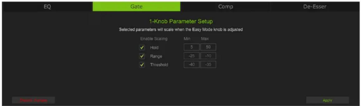
The last thing to do here is to click on "Apply" in the lower-right corner of the screen so the settings are saved and, well... applied! Or click on "Discard changes" in the lower-left corner of the screen to exit and return to the main Control Mode screen.
| Parameter Low | Value High Value | |
| Hold 1 ms 1000 | ms | |
| Range -60 dB 0 | dB | |
| Threshold -60 dB 0 | dB |
Parameter Setup - Compressor (Easy)
Compressors are used to reduce or limit transient peaks in a signal. If the signal is too hot, turn down that channel's gain, otherwise leave it alone. As the input level to the compressor increases, the output level increases linearly until the threshold point is reached. After that point, the output level no longer increases linearly. Instead, it increases at a reduced rate determined by the ratio setting.
The attack and release controls affect the rate of the gain change; attack affects the rate of the onset of gain reduction and release affects the recovery rate once the transient has passed.
Attack — Attack determines how quickly the compressor reacts once the signal is above threshold.
Short attack times allow compressing on short transients, while longer attack times cause these transients to be ignored. The range of the attack time varies from 0 ms to 50 ms.
Ratio — Ratio sets the amount of gain reduction applied as the signal exceeds the threshold level.
The range of the ratio of the compressor varies from 1:1 to 10:1.
Release — Release determines how long it takes for the compressor to end gain reduction once the signal drops back below the threshold. The range of the release speed varies from 0 ms to 500 ms.
Threshold — Threshold sets the threshold of the compressor in dB below 0 dBFS.
The range of the threshold setting varies from -60 dB to 0 dB.
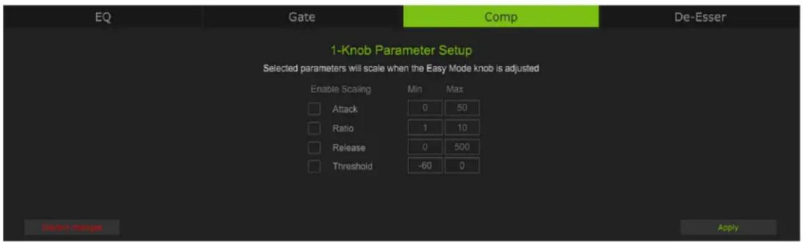
Like the EQ and gate tabs, simply mouse click in one of the min/max boxes and enter the minimum and maximum settings preferred. Continue to do so for each parameter. On the far left-hand side are several small gray boxes. Comp parameters that you would like added to the final mix need to be engaged, as well. To do so, mouse click on the box to give it a green check mark. We prefer full comp and checked all four boxes (as well as added some min/max settings), see below:

The last thing to do here is to click on "Apply" in the lower-right corner of the screen so the settings are saved and, well... applied! Or click on "Discard changes" in the lower-left corner of the screen to exit and return to the main Control Mode screen.
| Parameter Low | Value High Value | |
| Attack 0 ms 50 ms | ||
| Ratio 1:1 10:1 | ||
| Release 0 ms 500 ms | ||
| Threshold -60 dB | 0 dB |
Parameter Setup - De-Esser (Easy)
De-essers are specialized compressors that focus on and reduce or remove high frequencies and sibilance, especially "harsh" sounds such as "ess", "z", "ch", "j", "sh" and "ts". There are always exceptions to the rule, of course, but for the most part, sibilance is typically in the 3-8 kHz range.
"De-essing is a dynamic audio editing process, only working when the level of the signal in the sibilant range (the ess sound) exceeds a set threshold. De-essing temporarily reduces the level of high-frequency content in the signal when a sibilant ess sound is present. De-essing differs from equalization, which is a static change in level among many frequencies. However, equalization of the ess frequencies alone can be manipulated to reduce the level of sibilance... Over de-essing can result in the over-manipulation of transients, resulting in the softening or hardening of certain consonants, yielding undesirable effects."¹

Frequency — The frequency of sibilance typically runs between 2 kHz and 10 kHz. Here we give you an even wider spectrum range of 2 kHz to 16 kHz. The range of the frequency setting varies from 2 kHz to 16 kHz.
Range — This number determines the amount of de-essing, ranging from 1 dB to 10 dB.
Threshold — This parameter should be lowered until the 'esses' are eliminated.
The range of the threshold setting varies from -48 dB to 0 dB.
Lowering it too much, however, will result in a muffled sound (aka too much attenuation, or TMA on-the-fly).

Width — This number determines the width between end points; the smaller the number, the wider the end points are from each other. The range of the width setting varies from 0.0 to 10.
Like the EQ, gate, and comp tabs, simply mouse click in one of the min/max boxes and enter the minimum and maximum settings preferred. Continue to do so for each parameter. On the far left-hand side are several small gray boxes. De-Esser parameters that you would like added to the final mix need to be engaged, as well. To do so, mouse click on the box to give it a green check mark. We prefer full de-esser and checked all four boxes (as well as added some min/max settings), see below:

^1 De-essing
The last thing to do here is to click on "Apply" in the lower-right corner of the screen so the settings are saved and, well... applied! Or click on "Discard changes" in the lower-left corner of the screen to exit and return to the main Control Mode screen.
| Parameter Low | Value High Value | |
| Frequency 2 kHz 16 kHz | ||
| Range 1 dB 10 dB | ||
| Threshold -48 dB 0 dB | ||
| Width 0.0 10 | ||
Once all of these parameters' min/max settings have been entered and boxes checked, it's time to exit out of the screen and use the M-VOICE knob to determine the amount of dynamic processing... for THAT channel. Again, the M-VOICE knob was previously discussed on page 27.
Pro Control Mode
Here is a look at the initial Pro Control Mode screen in all its glory!

Many of the initial features we will take a look at have already been discussed in the Easy Control Mode section, but we shall discuss them again! Feel free to rush ahead if you already have a grip on these features or stay here and read through. Either way, we won't know!

Channel Name: Game (Stream) – There is nothing to click, turn, push, or anything else here. Yet, it remains quite important! Simply put, it displays which input's 'M-VOICE' button was clicked and what the Current Mix is set to. In this particular example, this is the "Game" input and the Current Mix is set to "Stream".
Control Mode – Awhile back we mentioned that there is an "Easy" Control Mode and a "Pro" Control Mode. The currently selected Control Mode will be in green text, while the other selection will be in white text. As confirmed via the screens displayed here – we are currently in "Pro" Control Mode.
Information (i) - Click on the encircled “(i)” to reveal a popover similar to what’s displayed below.

Shown here is information about the app and firmware. For the most part, this information is useless mumbo jumbo. There is no need to go here unless requested by Technical Support.
Click on the "X" in the upper-right corner to exit this screen.

Input Meters – On the bottom-left of the screen are the input meters. The stereo input meters display the relative level of each input channel. They should remain green with the occasional bump into the yellow zone. Turn down the volume if the input meter remains consistently yellow. If the input is too high [overloading], a clip indicator at the top of the meter will illuminate red. If clipping occurs, reduce the volume.

This only displays the input meter level. The input may be lowered by either (1) lowering the source of the input and/or (2) lowering the input fader level (located on the main mixing screen).
Ok friends, let's swing on over to the upper-right side of the screen now!
X - Clicking on the "X" will close out the Control Mode window and return you to the mixer view.

This is the only way to access the mixer view. The Control Mode screen cannot be “moved out of the way” to make changes to the mixer view.
RTA - RTA is discussed in depth on page 40.

natural_image
Abstract black and white diagonal striped pattern (no text or symbols)Expand/Contract – The Control Mode window may be scaled for a larger (or smaller) look, how 'bout them apples?! In the lower-right corner of the screen are several diagonal lines. These may be clicked (and held) while moving the mouse down and out/right (screen expands) or up and in/left (screen shrinks).

Again, regardless of screen size, the Control Mode screen cannot be "moved out of the way" to make changes to the mixer view.
Output Meters - The output meters display the output signal level, presented in stereo L/R. The meters should remain green with the occasional bump into the yellow zone. If there is too much yellow (or any red clipping), lower the output gain (more below) until it's gone and check the input channels, as well.
Output Gain - Located to the left of the output meters is the output gain control. Use it to raise/lower the output gain by up to ± 12 dB. This may be changed one of two ways: (1) hovering inside of the output gain circle, then rotating the mouse wheel to change the output gain; increments will be ± 1 dB, or (2) left (or right)-click (and hold) the mouse inside of the output gain circle while also moving the mouse up (increases gain) or down (decreases gain) by ± 0.xx for even more detailed settings!

Parameter Setup - EQ (Pro)
As you may have noticed, the remaining dynamics are book marked between the input and output meters. We will get to the gate, comp, and de-esser shortly, but we're going to start with the EQ.

line
| X | Y | | ---- | --- | | 1.00 | 0 | | 2.14 | 0 | | 3.14 | 0 | | 1.08 | 0 |Let's take a look at the five EQ bands to see how they function. Before that, though, take a quick peek in the upper-left corner of the M-VOICE popover. Notice the switch there? This switch allows for true bypass of the EQ circuitry to ensure that there is no coloration of the signal if the EQ is not needed. When this switch is disengaged, the EQ controls have no effect on the signal. You may use this switch to make an A/B comparison between the EQ'd signal and the signal without EQ. Click on this switch to turn EQ on or off. It will illuminate green when engaged and is gray when disengaged.
EQ Gain, Frequency, Q [Bandwidth], and Shelf/Bell
The gain and frequency may be changed by utilizing the mouse to tap-and-drag any of the five balls (representing each band) until the desired sound has been achieved. Moving a ball vertically changes the gain by up to ±24 dB. Moving a ball horizontally changes the frequency, ranging from 20 Hz to 20 kHz.
![MACKIE MainStream - EQ Gain, Frequency, Q [Bandwidth], and Shelf/Bell - 1](/content/2026/06/1402680/images/162817c4de3500e31e7028136a75e1ac0e58758e3515be2d8916ea0c4210dc30.jpg)
While the entire frequency range is 20 Hz to 20 kHz, each EQ band has its own range. This will be discussed shortly.
Q [bandwidth] ranges from 0.1 - 20.0. A smaller Q value results in a wider curve, while a larger Q value results in a narrower curve where frequencies may be zoomed in on more precisely. A smaller Q is generally intended for more musical purposes, while a larger Q is generally used when decreasing problem frequencies.
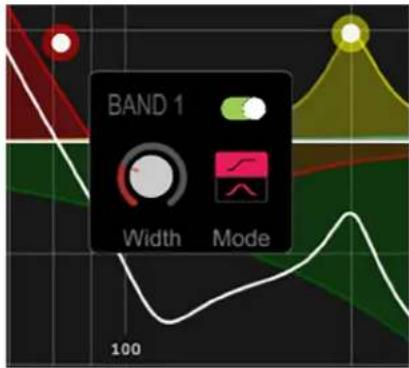
The Q may be changed in one of two ways. Either (1) hover over the EQ band's ball and scroll the wheel up or down to change the Q, or (2) mouse click on the band to reveal a popover as seen to the right. From here the Q (i.e. "Width") may be raised/lowered via the mouse wheel or mouse-click-hold while simultaneously moving the mouse up (increase Q) or down (decrease Q).
![MACKIE MainStream - EQ Gain, Frequency, Q [Bandwidth], and Shelf/Bell - 3](/content/2026/06/1402680/images/eb0f77b8382bcc806390d2bcffd5507c11c10b273d9756c89191b9eb359f6ed1.jpg)
Want to learn more about Q? Ok, let's nerd out together! Although the Q control does adjust the bandwidth of a filter, the Q value itself is dimensionless; it has no unit of measurement. Some equalizers use the fractional bandwidth of the filter, measured in octaves, to express this parameter. The two parameters are inversely related; a high Q value corresponds to a small fractional following table lists some equivalent Q and fractional bandwidth values.
| Q BW (oct) Q BW (oct) | |||
| 0.7 2 2.871 1/2 | |||
| 1.414 1 4.318 1/3 | |||
| 2.145 2/3 15 1/10 |
Two more things. First, as seen on the previous page, EQ Band 1 has an on/off switch. Not only that, all five EQ bands have an on-off switch... but we've only seen it on EQ band 1, thus far. Click on this switch to turn the selected band's EQ on or off. It will illuminate green when engaged and is gray when disengaged.
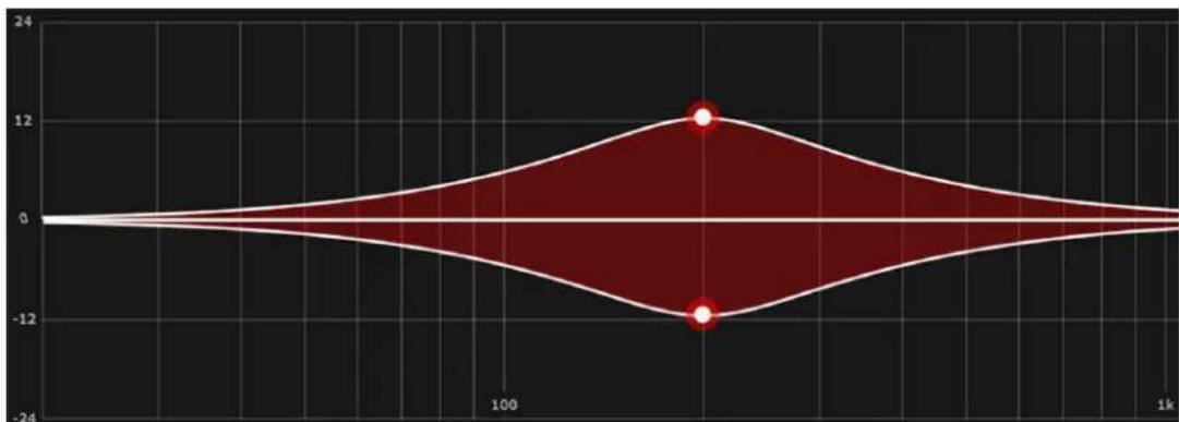
Lastly, also seen on the previous page is a shelf / bell option. One is available on bands 1 and 5. Simply click on which setting you prefer (with shelf on the top and bell on the bottom). Shelf boosts frequencies from the cut-off point upwards. A gentle roll-off may be assumed with shelf. On the other hand, bell boosts frequencies near the cut-off point then slowly decreases until it reaches a gain of zero. The chosen setting will illuminate the color of the band – hot pink for band 1 and pretty purple for band 5 – while the other option will be grayed out.
EQ Band 1
EQ band 1 provides up to 24 dB of boost or cut from 20 Hz to 200 Hz. The screenshots displayed below contain EQ band 1 at 200 Hz at ±12 dB. The Q is set at 0.71. The shelving screenshot is on top with the bell screenshot underneath. All other EQ bands are turned off.

area
| x | y | | ---- | ----- | | 100 | 0 | | 1k | 0 |BAND 1: 200 Hz at ±12 dB, 0.71 Q, SHELF
violin
| Bin Range | Frequency | | --------- | --------- | | 0 - 50 | 0 | | 50 - 100 | 0 | | 100 - 150 | 12 | | 150 - 200 | -12 | | 200 - 250 | 0 | | 250 - 300 | 0 | | 300 - 350 | 0 | | 350 - 400 | 0 | | 400 - 450 | 0 | | 450 - 500 | 0 | | 500 - 550 | 0 | | 550 - 600 | 0 | | 600 - 650 | 0 | | 650 - 700 | 0 | | 700 - 750 | 0 | | 750 - 800 | 0 | | 800 - 850 | 0 | | 850 - 900 | 0 | | 900 - 950 | 0 | | 950 - 1000| 0 | | 1000 - 1500| 12 | | 1500 - 2000| -12 | | 2000 - 2500| 0 | | 2500 - 3000| 0 | | 3000 - 3500| 0 | | 3500 - 4000| 0 | | 4000 - 4500| 0 | | 4500 - 5000| 0 | | 5000 - 5500| 0 | | 5500 - 6000| 0 | | 6000 - 6500| 0 | | 6500 - 7000| 0 | | 7000 - 7500| 0 | | 7500 - 8000| 0 | | 8000 - 8500| 0 | | 8500 - 9000| 0 | | 9000 - 9500| 0 | | 9500 - 1k | 12 |BAND 1: 200 Hz at ±12 dB, 0.71 Q, BELL
EQ Band 2
EQ band 2 provides up to 24 dB of boost or cut from 200 Hz to 4 kHz.
The screenshot displayed below contains EQ band 2 at 500 Hz at ±12 dB. The Q is set at 0.71. All other EQ bands are turned off.

violin
| Category | Value | | -------- | ----- | | Peak | 12 |BAND 2: 500 Hz at ±12 dB, 0.71 Q
EQ Band 3
EQ band 3 provides up to 24 dB of boost or cut from 200 Hz to 4 kHz.
The screenshot displayed below contains EQ band 3 at 1 kHz at ±12 dB. The Q is set at 0.71. All other EQ bands are turned off.

area
| x | y | | ---- | ----- | | 0 | 0 | | 100 | 0 | | 1k | 12 | | 1k | -12 |BAND 3: 1000 Hz (1 kHz) at ±12 dB, 0.71 Q
EQ Band 4
EQ band 4 provides up to 24 dB of boost or cut from 200 Hz to 4 kHz.
The screenshot displayed below contains EQ band 4 at 2.5 kHz at ±12 dB. The Q is set at 0.71. All other EQ bands are turned off.

violin
| Category | Value | | -------- | ----- | | Red | 4 | | Yellow | 5 | | Green | 6 |BAND 4: 2500 Hz (2.5 kHz) at ±12 dB, 0.71 Q
EQ Band 5
EQ band 5 provides up to 24 dB of boost or cut from 4 kHz to 20 kHz.
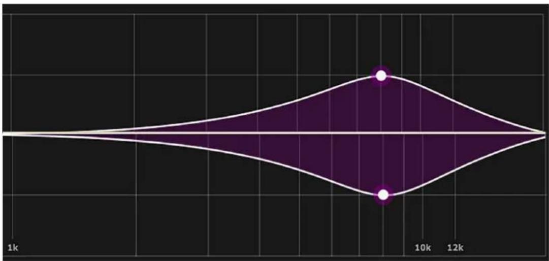
The screenshot displayed below contains EQ band 5 at 8 kHz at ±12 dB. The Q is set at 0.71.
The shelving screenshot is on top with the bell screenshot underneath. All other EQ bands are turned off.

area
| x | y | | ---- | ----- | | 1k | 0 | | 10k | 1 | | 12k | 0 |BAND 5: 8000 Hz (8 kHz) at ±12 dB, 0.71 Q, SHELF
violin
| Category | Value | | -------- | ----- | | Peak | 10k | | Min | 12k |BAND 5: 8000 Hz (8 kHz) at ±12 dB, 0.71 Q, BELL
RTA
RTA stands for "Real-Time Analyzer" and it measures and displays the sound of the corresponding input – amplitude versus frequency components of a continuous signal – via DSP. Many audio signals are highly dynamic: music, speech and even environmental noise contain significant changes in spectral content as a function of time. An RTA allows you to see what you hear so you may easily locate and eliminate feedback and other anomalies, while seeing the EQ changes in real time.
A screenshot of an RTA in action may be seen below:

line
| Frequency | Value | | --------- | --------- | | 70 Hz | -4.4dB |RTA ON

line
| Time | Value | |------|-------| | 0 | -58 | | 100 | -12 | | 130 | 0 | | 160 | 10 | | 190 | 0 | | 220 | -18 | | 250 | 10 | | 280 | 0 | | 310 | 0 |RTA OFF
Parameter Setup - Gate (Pro)
Gates are typically used to reduce leakage from open microphones. Signals below the threshold level are muted, while signals above the threshold get to pass through. The range control changes the rule slightly. Signals below the threshold are attenuated by the amount of the range setting, while signals above the threshold get to pass through.
The operation of the gate is further modified by the attack, hold, and release controls. In order to open the gate, the input signal must exceed the threshold for at least the duration of the attack time. This is useful for helping the gate discriminate between something that is short duration and long duration.
Once the gate has opened, the hold time begins. The hold timer resets any time the input signal crosses the threshold again, as long as it remains above the threshold for longer than the attack setting. After the hold time passes, the gain falls at a rate determined by the release setting. The range control allows the gate to remain partly open, even if the input is below the threshold.

Threshold — Threshold determines the level at which the gate acts on the incoming signal.
The range of the threshold setting varies from -60 dB to 0 dB.
Range — Range determines how far the gain drops once the signal is below threshold. Setting the range control to something in the -20 to -30 dB range allows some amount of signal leakage when the gate is closed, which may make its action more subtle (less abrupt) and therefore less noticeable. The range of the gated signal varies from -60 dB to 0 dB.
Release — Release determines how long it takes for the gain to fall to the setting of the range control once the signal falls below threshold and the hold time elapses. The range of the release speed varies from 0 ms to 100 ms.
Hold — Hold sets a fixed time that the gate remains open once the signal drops below the threshold setting. During the hold time, the gain is held constant, whereas during the release time, the gain is falling at the release rate. The range of the hold time varies from 1 ms to 1000 ms.
Attack — Attack determines how quickly the gate opens once the signal is above threshold. Short attack times allow triggering on short transients, while longer attack times cause these transients to be ignored. The range of the attack time varies from 0 ms to 50 ms.
These parameters may be changed one of two ways: (1) hovering inside of the appropriate parameter's circle, then rotating the mouse wheel to change the parameter, or (2) left (or right)-click (and hold) the mouse inside of the appropriate parameter's circle while also moving the mouse up (increases parameter) or down (decreases parameter) by ±0.xx for even more detailed settings!
Above the five parameter's circles are three additional things to check out. From left-to-right, they are...

Gate On/Off — Tap the gate button to turn the gate on or off. It will illuminate cyan when engaged (as seen above and to the left) and is gray when disengaged. The gate may be adjusted whether the gate is on or off.
Gate Meter — This horizontal meter displays the amount of gain reduction.
(1) — Mouse-clicking on the “(1)” makes the current view (displayed above) disappear and the one to the left appear in its stead. Notice that the “(1)” is illuminated green above and is gray to the left.
Directly to the left of the M-VOICE "Amount" knob is an icon containing three horizontal fader sliders. Mouse-click on this icon to reveal something similar to what may be seen below:


Simply mouse click in one of the min/max boxes and enter the minimum and maximum settings preferred. Continue to do so for each parameter. On the far left-hand side are several small gray boxes. Gate parameters that you would like added to the final mix need to be engaged, as well. To do so, mouse click on the box to give it a green check mark. We prefer full gate and checked all three boxes (as well as added some min/max settings), see below:

The (almost) last thing to do here is to click on "Apply" in the lower-right corner of the screen so the settings are saved and, well... applied! Or click on "Discard changes" in the lower-left corner of the screen to exit and return to the main Control Mode screen.

pie
| Value | Percentage | |---|---| | 69 | +19% | | Amount | (implied by context) |The (very) last thing to do here is to rotate the M-VOICE "Amount" knob. It may be changed one of two ways: (1) hovering inside the circle, then rotating the mouse wheel to change the percentage, or (2) left (or right)-click (and hold) the mouse inside of the circle while also moving the mouse up (increases %) or down (decreases %) by ±1% for even more detailed settings!
The BIG number (inside the circle) displays the total percentage of the EASY CONTROL MODE level, whereas the smaller number (to its right) displays the ± percentage change OF THE SELECTED DYNAMIC. At least one parameter needs to be applied in order for the dynamic to follow the easy control mode knob. Mouse-click on
the arrowed-semi-circle underneath the smaller number to reset the "Amount" knob to the current level of the easy control knob.
| Parameter Low | Value High Value Default | ||
| Gate Enable Off On | On | ||
| Threshold -60 dB | 0 dB -58 dB | ||
| Range -60 dB | dB -12 dB | ||
| Release 0 ms | 100 ms | ||
| Hold 0 ms | 1000 ms | 100 ms | |
| Attack 0 ms | 50 ms | 1 ms |
Parameter Setup - Compressor (Pro)
Compressors are used to reduce or limit transient peaks in a signal. If the signal is too hot, turn down that channel's gain, otherwise leave it alone. As the input level to the compressor increases, the output level increases linearly until the threshold point is reached. After that point, the output level no longer increases linearly. Instead, it increases at a reduced rate determined by the ratio setting.
The attack and release controls affect the rate of the gain change; attack affects the rate of the onset of gain reduction and release affects the recovery rate once the transient has passed.
Threshold — Threshold sets the threshold of the compressor in dB below 0 dBFS. The range of the threshold setting varies from -60 dB to 0 dB.

Ratio — Ratio sets the amount of gain reduction applied as the signal exceeds the threshold level.
The range of the ratio of the compressor varies from 1:1 to 10:1.
Gain — Gain adds make-up gain to the output of the compressor. This is useful to make the apparent volume of the signal the same with the compressor in and out of the signal chain. The range of the make-up gain varies from -36 dB to 12 dB.
Attack — Attack determines how quickly the compressor reacts once the signal is above threshold. Short attack times allow compressing on short transients, while longer attack times cause these transients to be ignored. The range of the attack time varies from 0 ms to 50 ms.
Release — Release determines how long it takes for the compressor to end gain reduction once the signal drops back below the threshold. The range of the release speed varies from 0 ms to 500 ms.
Soft Knee / Hard Knee Compression — This determines the shape of the gain reduction curve at the threshold level. When set to hard [top, default, selected above], the gain reduction curve changes abruptly at the threshold level. When set to soft [bottom], the gain reduction curve changes gently as it transitions to the final ratio amount.
These parameters may be changed one of two ways: (1) hovering inside of the appropriate parameter's circle, then rotating the mouse wheel to change the parameter, or (2) left (or right)-click (and hold) the mouse inside of the appropriate parameter's circle while also moving the mouse up (increases parameter) or down (decreases parameter) by ±0.xx for even more detailed settings!
Above the five parameter's circles are three additional things to check out. From left-to-right, they are...

gauge
| Value | |---| | 25% | | -25% |Comp On/Off — Tap the comp button to turn the comp on or off. It will illuminate purple when engaged (as seen above) and is gray when disengaged (as seen to the left). The comp may be adjusted whether the comp is on or off.
Comp Meter — This horizontal meter displays the amount of gain reduction.
(1) — Mouse-clicking on the “(1)” makes the current view (displayed above) disappear and the one to the left appear in its stead. Notice that the “(1)” is illuminated green above and is gray to the left.
Directly to the left of the M-VOICE "Amount" knob is an icon containing three horizontal fader sliders. Mouse-click on this icon to reveal something similar to what may be seen below:

Simply mouse click in one of the min/max boxes and enter the minimum and maximum settings preferred. Continue to do so for each parameter. On the far left-hand side are several small gray boxes. Comp parameters that you would like added to the final mix need to be engaged, as well. To do so, mouse click on the box to give it a green check mark. We prefer full comp and checked all four boxes (as well as added some min/max settings), see below:
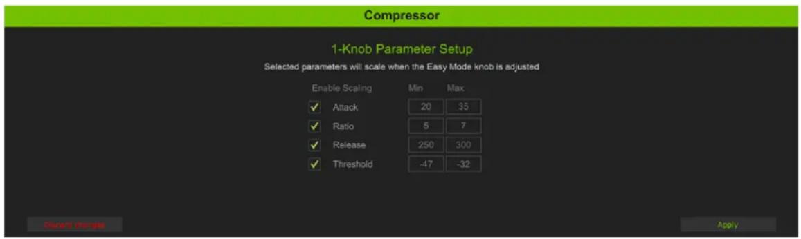
The (almost) last thing to do here is to click on "Apply" in the lower-right corner of the screen so the settings are saved and, well... applied! Or click on "Discard changes" in the lower-left corner of the screen to exit and return to the main Control Mode screen.
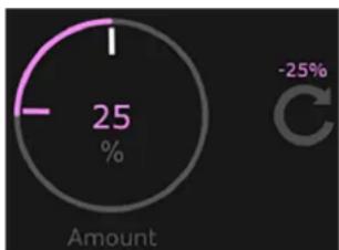
pie
| Value (%) | | :--- | | 25 | | -25 |The (very) last thing to do here is to rotate the M-VOICE "Amount" knob. It may be changed one of two ways: (1) hovering inside the circle, then rotating the mouse wheel to change the percentage, or (2) left (or right)-click (and hold) the mouse inside of the circle while also moving the mouse up (increases %) or down (decreases %) by ±1% for even more detailed settings!
The BIG number (inside the circle) displays the total percentage of the EASY CONTROL MODE level, whereas the smaller number (to its right) displays the ± percentage change OF THE SELECTED DYNAMIC. At least one parameter needs to be applied in order for the dynamic to follow the easy control mode knob.
Mouse-click on the arrowed-semi-circle underneath the smaller number to reset the "Amount" knob to the current level of the easy control knob.
| Parameter Low | Value High Value Default | ||
| Comp Enable Off On | On | ||
| Threshold -60 dB | 0 dB 0 dB | ||
| Ratio 1:1 10:1 10:1 | |||
| Gain -36 dB | 12 dB | 0 dB | |
| Attack | 0 ms | 50 ms | 1 ms |
| Release | 0 ms | 500 ms | 100 ms |
| Knee Soft | Hard Hard | ||
Parameter Setup - De-Esser (Pro)
De-essers are specialized compressors that focus on and reduce or remove high frequencies and sibilance, especially "harsh" sounds such as "ess", "z", "ch", "j", "sh" and "ts". There are always exception to the rule, of course, but for the most part, sibilance is typically in the 3-8 kHz range.
"De-essing is a dynamic audio editing process, only working when the level of the signal in the sibilant range (the ess sound) exceeds a set threshold. De-essing temporarily reduces the level of high-frequency content in the signal when a sibilant ess sound is present. De-essing differs from equalization, which is a static change in level among many frequencies. However, equalization of the ess frequencies alone can be manipulated to reduce the level of sibilance... Over de-essing can result
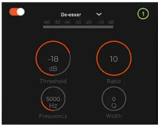
other
| Metric | Value | |--------|-------| | Threshold | -18 dB | | Frequency | 5000 Hz | | Ratio | 10 | | Width | 0 Q |in the over-manipulation of transients, resulting in the softening or hardening of certain consonants, yielding undesirable effects."2
Threshold — This parameter should be lowered until the 'esses' are eliminated.
The range of the threshold setting varies from -60 dB to 0 dB.
Lowering it too much, however, will result in a muffled sound (aka too much attenuation, or TMA on-the-fly).

Ratio — Ratio sets the amount of gain reduction applied as the signal exceeds the threshold level.
The range of the ratio of the de-esser varies from 1.00:1 to 10.00:1.
Frequency — The frequency of sibilance typically runs between 2 kHz and 10 kHz.
The range of the frequency setting varies from 2 kHz to 16 kHz.
Width — This number determines the width between end points; the smaller the number, the wider the end points are from each other. The range of the width setting varies from 0.00% Q to 10.00% Q.
These parameters may be changed one of two ways: (1) hovering inside of the appropriate parameter's circle, then rotating the mouse wheel to change the parameter, or (2) left (or right)-click (and hold) the mouse inside of the appropriate parameter's circle while also moving the mouse up (increases parameter) or down (decreases parameter) by ±0.xx for even more detailed settings!
Above the four parameter's circles are three additional things to check out. From left-to-right, they are...

gauge
| Value | Change (%) | |---|---| | 82 | +32 |De-Esser On/Off — Tap the de-esser button to turn the de-esser on or off. It will illuminate a red-ish orange when engaged (as seen above) and is gray when disengaged (as seen to the left). The de-esser may be adjusted whether the de-esser is on or off.
Comp Meter — This horizontal meter displays the amount of attenuation.
(1) — Mouse-clicking on the “(1)” makes the current view (displayed above) disappear and the one to the left appear in its stead. Notice that the “(1)” is illuminated green above and is gray to the left.
Directly to the left of the M-VOICE "Amount" knob is an icon containing three horizontal fader sliders. Mouse-click on this icon to reveal something similar to what may be seen below:

Simply mouse click in one of the min/max boxes and enter the minimum and maximum settings preferred. Continue to do so for each parameter. On the far left-hand side are several small gray boxes. De-Esser parameters that you would like added to the final mix need to be engaged, as well. To do so, mouse click on the box to give it a green check mark. We prefer full de-esser and checked all four boxes (as well as added some min/max settings), see below:

The (almost) last thing to do here is to click on "Apply" in the lower-right corner of the screen so the settings are saved and, well... applied! Or click on "Discard changes" in the lower-left corner of the screen to exit and return to the main Control Mode screen.

pie
| Value (%) | | :--- | | 82 | | +32 |The (very) last thing to do here is to rotate the M-VOICE "Amount" knob. It may be changed one of two ways: (1) hovering inside the circle, then rotating the mouse wheel to change the percentage, or (2) left (or right)-click (and hold) the mouse inside of the circle while also moving the mouse up (increases %) or down (decreases %) by ±1% for even more detailed settings!
The BIG number (inside the circle) displays the total percentage of the EASY CONTROL MODE level, whereas the smaller number (to its right) displays the ± percentage change OF THE SELECTED DYNAMIC. At least one parameter needs to be applied in order for the dynamic to follow the easy control mode knob. Mouse-click on the arrowed-semi-circle underneath the smaller number to reset the "Amount" knob
to the current level of the easy control knob.
| Parameter Low | Value High Value Default | ||
| De-Esser Enable Off On On | |||
| Frequency 2 kHz 16 kHz 5 kHz | |||
| Range -15 dB 0 dB 0 dB | |||
| Threshold -60 dB 0 dB -18 dB | |||
| Width | 0.00% Q | 10.00% Q | 0.00% Q |
Chapter 5: M-FX



Introduction

Mentioned on pages 15-16 is the description on how to open a channel's M-FX. As seen to the left, the M-FX of each hardware and virtual input may be accessed by a simple mouse-click on that input.
The M-FX area contains four - count 'em, FOUR!! - different effects that may be set to your preference. These include, the Atomizer Reverb, Chronotronic Delay, Telephone, and StreamFX Voice Changer! We will go through all M-FX, starting with the Atomizer Reverb.

The M-FX screen will not display all four effects simultaneously as shown above, but rather, each one individually.

Anything from zero up to four effects may be used simultaneously.
Furthermore, these are on a PER-CHANNEL basis, so there are (basically) an unlimited amount of effects options at your disposal!
Atomizer Reverb
The reverb may be adjusted by moving the knobs via click-and-rotate. The FX may be adjusted whether the effects are on or off.
On-Off — Located near the top of the display is the Atomizer Reverb on/off switch. Click on the FX switch(es) to turn them on or off for that channel. It will illuminate green when engaged and is black when disengaged.
Pre-Delay — When listening to a live performance, direct sounds are reached first, followed by reverberation caused by room reflections. The pre-delay is the amount of time between when the direct sounds arrive and when the reflections arrive.
The speed of sound is approximately 340 meters per second (1100 feet per second). This means that in one millisecond, it travels 0.34 meters (1.1 feet). As a rough idea, think of 1 ms as the time it takes for sound to travel one foot.
Decay — This represents the decay time of the reverb.
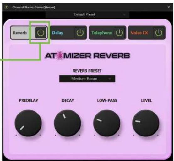
Low-Pass — This applies a low-pass filter to the reverbed signal and rolls off the higher frequencies.
Reverb Level — This sets the reverb FX send level for the currently selected channel.
Presets — Presets save parameters and may be recalled as needed. Mackie Matrix comes with a library of factory presets. There are also user presets. These may be created for each preset type.
An entire chapter is dedicated to presets. This includes detailed instructions and multiple screenshots every step of the way. Please check it out on pages 56-61.
ChronoTronic Delay
The delay may be adjusted by moving the knobs via click-and-rotate. The FX may be adjusted whether the effects are on or off.
On-Off — Located near the top of the display is the ChronoTronic Delay on/off switch. Click on the FX switch(es) to turn them on or off for that channel. It will illuminate green when engaged and is black when disengaged.
Delay Time (Decay) — This knob sets the current delay time.
Feedback — This controls how much of the delayed signal is routed back to the input of the delay section to create multiple echoes. Each time the signal is fed back, the delayed signal becomes quieter (so the echo won't go on forever unless set at 100%).
Low-Pass — This applies a low-pass filter to the delayed signal and rolls off the higher frequencies.

Delay Level — This sets the delay FX send level for the currently selected channel.
Presets — Presets save parameters and may be recalled as needed. Mackie Matrix comes with a library of factory presets. There are also user presets. These may be created for each preset type.
An entire chapter is dedicated to presets. This includes detailed instructions and multiple screenshots every step of the way. Please check it out on pages 56-61.
Telephone
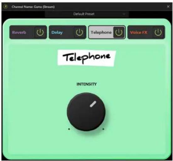
The telephone effect may be adjusted by moving the knob via click-and-rotate. The FX may be adjusted whether the effects are on or off.
On-Off — Located near the top of the display is the Telephone on/off switch. Click on the FX switch(es) to turn them on or off for that channel. It will illuminate green when engaged and is black when disengaged.
Intensity — This effect simulates the sound of someone talking on the phone. It essentially limits the frequency response, resulting in a "thinner", more lo-fi sound. This knob sets the intensity of the telephone effect.
Presets — Presets save parameters and may be recalled as needed. Mackie Matrix comes with a library of factory presets. There are also user presets. These may be created for each preset type.
An entire chapter is dedicated to presets. This includes detailed instructions and multiple screenshots every step of the way. Please check it out on pages 56-61.
StreamFX Voice Changer
The voice changer contains three different options to choose from: pitch shift, voice disguise, and robot voice. Let's say we check them out, shall we...? The FX may be adjusted whether the effects are on or off.
On-Off — Located near the top of the display is the StreamFX Voice Changer on/off switch. Click on the FX switch(es) to turn them on or off for that channel. It will illuminate green when engaged and is black when disengaged.
Voice Disguise — The middle StreamFX Voice Changer selection is "Voice Disguise". Use it to -
When the disguise intensity ball is clicked-and-dragged to the left, it lowers the intensity of the disguise and the further right it is, the more intense the disguise effect is. Right-click on the disguise intensity ball to re-center it. When the ball is to the far-left, there is little-to-no disguise. It has to be up at I
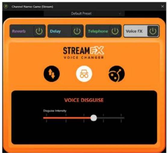
This is the kind of voice that's heard when watching television, for example, and the person's face is pixelated and the voice is altered. They do not want to be known. This can be selected if a guest of the podcast or livestream wants their true voice to be altered, as an example.

Pitch Shift — This ball sets the pitch of the voice. When the pitch shift ball is clicked-and-dragged to the left, it deepens the voice, and anything to the right of the middle increases the pitch. Right-click on the pitch shift ball to re-center it.
Robot — The third and final StreamFX Voice Changer selection is "Robot". When selected – and engaged – the voice alters, sounding eerily like a robot from the future. There are three robot voice selections to choose from: small, medium, and large.
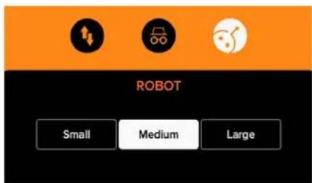
Presets — Presets save parameters and may be recalled as needed. Mackie Matrix comes with a library of factory presets. There are also user presets. These may be created for each preset type.
An entire chapter is dedicated to presets. This includes detailed instructions and multiple screenshots every step of the way. Please check it out on pages 56-61.
Chapter 6 : Samples
Introduction
We briefly discussed the sampler channel way back when, but now it's time to do more of a deep dive. Before the deep dive, though, let's do a quick refresher.
Sampler Channel

The sampler channel strip contains the following:
Sampler Channel Fader
The sampler channel fader adjusts the level of the samples going to the output. The volume level ranges from off (silent) to max (full volume). It is a global control, affecting the level of all samples.
M-VOICE
Above the sampler fader and input meters is the M-VOICE popover. There is one for every input, including the sampler. M-VOICE was discussed in chapter 4, pages 24-46.
M-FX
Above the sampler fader and input meters is the M-FX popover. There is one for every input, including the sampler. M-FX was discussed in chapter 5, pages 47-49.
SOLO
Solo offers the opportunity to audition the sampler channel before it is added to the mix. Whenever a channel's solo is engaged, only the soloed channel(s) may be heard. It illuminates amber when engaged.
MUTE
Mute essentially “turns off” the signal on the sampler channel. It illuminates red when engaged. Additionally, the fader turns from green to red.
Sample Pads

Clicking on one (or more) of the eight samples results in playback of the saved sample. When clicked, the sample will play. Additionally, a "timer" will be displayed for the duration of the playback. If no sample is assigned, it will remain grayed out, as seen to the left.
Displayed below the eight samples (and directly to the right of the sampler solo and mute) is a letter book marked by two outward-facing arrows. Clicking on the arrows switches between the sample banks. There are four banks (A-D) with eight spots for samples in each bank... that's a total of 32 possible samples that may be added!
Play Sample

Something mentioned several pages back is that you're able to hover over a multitude of features. When hovering, a popover will be displayed indicating what the feature will do when selected.
As seen in the screenshot to the left, clicking on the right-facing arrow placed inside the circle will play the sample that is loaded on that particular pad.
Notice that the bank and bank number reside in the upper-right corner of each sample regardless of the name, color, pad mode, etc. These represent each bank and sample and cannot be changed or removed. Trust us, it's for the best, as it is for easy identification, even after you rename it something goofy.
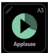
When a sample is playing, a timer shows how much time has elapsed and how much time remains. In the example to the left, we clicked on the 'Applause' sample (sample bank A, pad number 3). The "darker" area shows how much time has elapsed, while the rest will be played momentarily.
Bank Switching

As mentioned on the previous page, displayed below the eight samples (and directly to the right of the sampler solo and mute) is a letter book marked by two outward-facing arrows. Clicking on the arrows switches between the sample banks. There are four banks (A-D) with eight spots for samples in each bank... that's a total of 32 possible samples that may be added!
The way to switch between banks is to simply use the left- and right-facing arrows. Notice in this image that the right-facing arrow is illuminated while the left-facing arrow and bank letter remain visible, but greyed out. This is because the mouse is hovering over the right-facing arrow. Additionally, you cannot “go left” to arrive at Bank D.
Pad Customization

Since we are banking – yes, pun very much intended – on you keeping the eight pre-loaded samples, let's go ahead and tap the right-arrow so 'Bank B' appears.

While eight samples have been baked into 'Bank A', by no means are you forced to keep them. Feel free to keep, change, delete, whatever... it's your setup!

All eight samples displayed to the left are gray, indicating that no samples have been assigned to them yet. This is also true of the remaining banks.
If we use the mouse to hover over one of the sample boxes, it asks if you want to play the loaded sample file (which you can't because there is no sample loaded yet). I mean, sure, you can try, but nothing will play!
However, just like the virtual devices mentioned way, way back, samples may also be edited using the pencil icon located in the upper-left corner. Clicking on it opens up the editing features of that sample (see below-right).
Mentioned previously – and seen to the right – is the fact that you are able to edit samples. This includes a custom pad name, pad color, pad mode, play style, an option for looping, and hotkey assignation.
- Pad Name – Changing the name is as simple as mousing over to "Pad Name", then clicking. The cursor arrives awaiting your input with bated breath. Blinking. Blinking. Blinking. Go ahead and type in your own fancy pad name!

The modern English alphabet consists of 26 letters. I was able to enter this alphabet FOUR times over without 'hitting any walls'. Granted, only 14 characters show up at a time, so best to use something shorter (and thus, readable).
- Pad Color – The current color of the pad has a check mark. This may be updated to a color that suits you more. Use the mouse to hover over the color, then click to select.
- Pad Mode – There are two different pad modes to choose from with 'Sample' as the default... but it may be changed. Simply tap the pad mode you desire. The tapped pad mode will illuminate light gray, like 'Sample' is to the right. The other selection will remain in the dark. We are currently working in the samples section and will check out how bleep works next.
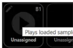

- Play Style – There are three different play styles to choose from with 'Stop' as the default... but it may be changed. Listed below are the three play style modes and their playback behaviors:
- Stop – Stop plays the sample from start to finish. The sample may be stopped early by pressing the sample pad again. If pressed again, though, it will restart the sample from the beginning.
- Pause – Pause also plays the sample from start to finish. However, the sample may be paused by pressing the sample pad again. If the sample pad is pressed a third time, the sample will continue to play from the paused point. The sample may be played and paused until the end of the sample is reached.
- Replay – Replay is similar to Stop as it also plays the sample from start to finish. In fact, it will do so if you allow it. However, you didn't set this up as a Stop. It's a Replay!
With Replay, you're supposed to tap the sample pad again. This ends the currently playing sample and starts the sample playback from the beginning.

As you might expect, only one play style may be selected per sample pad (although it would be quite odd to have more than one!).

All eight sample pads are on their own chain. What this means is that multiple samples may be played simultaneously.
- Sample File – As seen in the screenshots below, unassigned pads may either have samples loaded (left) or a new one may be recorded (right). Let's take a quick look at both.


- Load File – When attempting to load a file, you are granted the option of loading it from the computer's hard drive, an attached thumb drive, portable disk, or other. Just remember where it was saved for easy recall!
As seen in the image to the left, we loaded a sample named "Best Sample Ever.wav". We have also decided to name the pad the same thing, although you can name it whatever you so desire. However, the sample file name will remain the same as whatever it was when loaded.
- Record New – If you want to record a sample, the very first step is to make sure that you have the correct bank and sample pad selected. For this example, we will use Bank B, Sample 5. As such, B5 is displayed in the upper-left corner of all screenshots displayed below.
Next, select 'Click to start recording' to begin recording immediately (Image A). Once clicked, the record time is displayed and a different image – a black square inside of an even bigger red square – also appears (Image B). Click this square to stop recording and assign it to the assigned pad (Image C).
Now, if 'Record New' was an accidental click, simply click on 'Cancel' at the bottom of the screen to return to the previous view. Note that a recording may still be cancelled after it has started (as seen in Image B below).
Since it was not an accidental click, we venture on to images C and D... in both, the options are to (1) 'Click to preview recording', (2) change the file name, (3) 'Save', and (4) 'Delete'. The only difference between them is that in Image D, the recording is, in fact, currently previewing the recording. You can either let it play out to the end or click again to stop.


IMAGE A IMAGE EIMAGE DAMAGE CIMAGE B
Continuing on, file names default to 'record_0001', 'record_0002', 'record_0003', 'record_0004', etc., but feel free to rename it what you want. Note that the File Name and Pad Name do not have to be named the same thing. Once you have updated the File Name, go ahead and save it by clicking on... you guessed it: 'Save!'
If the new recording isn't up to snuff, don't worry. It happens to the best of us, it happens to all of us. You can exit out by clicking anywhere in the mixer area of Mackie Matrix, the "x" at the end of 'File Name', or 'Delete' at the bottom of the screen.
Image E shows the final saved new recording on Bank B, Sample 5. We kept the file name at its default 'record_0001', but changed the pad name to "New Recording". It won't be difficult for you to create a better sounding name than that, though! We also left the 'Play Style' at 'Stop', but (again), feel free to change to what you desire.
Ok, that wraps up the 'Sample File' section, but there are two more features at the bottom of the screen.
- Looping – If this switch is to the right (illuminates green), looping has been engaged. This means that once the sample has finished playing, it will “loop back” to the beginning and play the sample again repeatedly until the sample pad is clicked on again. Looping is available regardless of the chosen play style.
- Hotkey Assign – Lastly, you can assign a key – or set keys [e.g. Ctrl+, Alt+, Shift+, etc.] – that will trigger the sample when pressed. In order to assign a key (new or otherwise), click on the “x” at the end of “Press key...”. From there, simply tap the key (or keys) that you want assigned to the sample.

By default, the multifunction keys on MainStream are mapped as hotkeys F1 through F6 (the first six samples in Bank A of Mackie Matrix). These are only the default settings and you are able to map it how you want.
We discussed 'Pad Mode' a few pages back, but have only been covering the 'Sample' section of it, thus far. But what happens if we select 'Bleep' instead...? Let's find out!

- Bleep – As seen to the left, it doesn't look like there are many differences between 'Sample' and 'Bleep' – and there aren't – but there are a couple of things to note. Let's take a very quick look from top-to-bottom.
The 'Pad Name' and 'Pad Color' were already discussed in full on page 52.
The 'Pad Mode' was also discussed on the same page, but 'Sample' was selected there instead of 'Bleep'. When 'Bleep' is the selected 'Pad Mode', 'Play Style' is replaced with 'Bleep Style' and the 'Looping' option disappears, as well.
If 'Bleep' is the selected 'Pad Mode', the pad acts as a momentary switch, only activating the signal when the pad is clicked and held. The 'Bleep' will stop once the mouse button (or hotkey) has been released.
- 1kHz Tone – Whether we mean to do it or not, it happens. People swear. Clicking on the pad that has this 'Bleep Style' selected releases a 1kHz tone [by default], a high-pitched beep. Everyone with headphones will hear the salty language, but the audience will just get the beep.
As mentioned above, the tone is simply the default, but you can make the 'Bleep Style' be whatever you want. Just tap the 'Sample' button. Out of thin air – and below the 'Bleep Style' – are two additional options: 'Load File' and 'Record New'. We just went over these, so will not reiterate here. Simply go back to pages 53-54 and start there.
Lastly, 'Hotkey Assign' was discussed above!
One final difference between 'Sample' and 'Bleep': Samples that have been assigned to a pad results in a typical "Play" symbol (right-facing arrow, A7) versus bleeps which will result in a playback button of "?#". In fact, as a default, a 1kHz has already been assigned to pad A8. See to the right for examples of a 'Sample' and a 'Bleep'.

Chapter 7: Presets
Introduction
Presets save parameters on individual input or output channels and on particular DSP blocks such as EQ, dynamics, FX, etc. For example, a favorite microphone EQ setting may be saved as a preset and recalled as needed.
Mackie Matrix comes with a library of factory presets. There are also user presets. These may be created for each preset type. The number of user presets available is limited only by the available space on the computer. Presets are generally set ahead of time, not as an event is taking place. Presets are stored on the computer.
The following preset types are available:
Input channel:
• M-VOICE EQ
• M-VOICE Gate
• M-VOICE Compressor
• M-VOICE De-Esser
• M-FX Reverb
- M-FX Delay
• M-FX Telephone
• M-FX Voice FX
Output channel:
• M-EQ
The first thing we will do is take a look at factory presets vs user presets. From there, channel presets and DSP presets may be selected [factory] or created [user].
Factory Presets vs User Presets
There are factory presets and user presets. Feel free to start with a factory preset, manipulate to your liking, then save as a user preset. We will start with what each one looks like and how they work.
As you may see, a wide variety of factory presets are available to choose from. These are graced with a name of said factory preset. Simply mouse click the preferred preset to load. This will update the current selection. It's certainly easier to make updates from a factory preset versus updating parameters from a zeroed out board!
Simply mouse click on "Presets" to reveal a popover (with a channel's EQ input preset seen below). The popover displays a list of user and factory presets to choose from, as well as the opportunity to...
- save the preset
- load the preset and/or
- clear all presets

Click-and-hold on a preset – User or Factory – so it is highlighted then release to select. Once released, all appropriate parameters change to match the stored preset. You'll hear the changes immediately and should notice visible changes to the settings, as well. Let's take a look at each of the choices.
Save — The save preset button stores the current state of the processing into a new user preset. After clicking on 'Save', you will be asked to name the preset.


The name of the preset is the name of the preset, not the channel input, master output, etc.
Load — Load works a little bit differently. Once "Load" has been mouse-clicked, the computer's hard drive will appear [Default: This PC > Documents > M-Voice > ||Dynamics||]. Double-clicking on one of the presets recalls its parameters. Upon load, all appropriate parameters change to match the stored preset. You'll hear the changes immediately and should ice visible changes to the settings, as well. The presets are listed in alpha-numeric order.
Clear All — Mouse-clicking on "Clear All" clears all current parameters to their default settings.
Please be careful!! When a preset is cleared, all currently set parameters will be deleted (with no undo), and there is no confirmation dialog to help prevent accidents. It might help to save the settings first, then to "Clear All".
Default — Mouse-clicking on "Default" resets ALL parameters to their factory default settings.

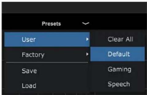

Default is only available in the "Presets" pull-down. The "Presets" pull-down will affect ALL dynamics – EQ, Gate, Comp, and De-Esser – whereas the "Equalizer" pull-down ONLY affects the parameters of the EQ.
DSP Presets
DSP presets change only a portion of an input or output channel. This includes EQ, gate, compressor, de-esser, and M-FX. However, DSP presets do NOT change the on / off state. This allows a user to audition presets with the processor on or off, as desired.
From the EQ channel view you are able to set a preset for the channel's EQ. From the gate, compressor, and de-esser channel view you are able to set a preset for the dynamics.

EQ PRESETS GATE PRESETS
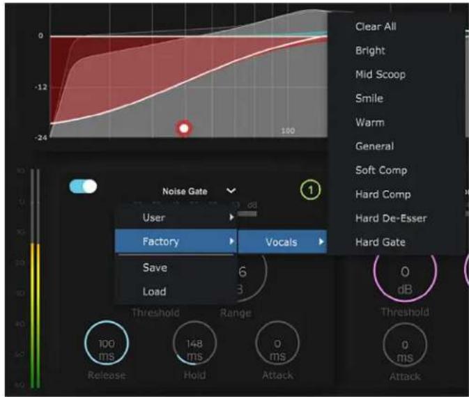
The compressor and de-esser factory presets are displayed below.

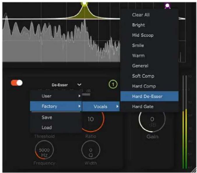
COMPRESSOR PRESETS DE-ESSER PRESETS
Notice how all factory settings look exactly the same. Literally zero difference between them. "Bright" through to "General" are all considered standard EQ settings, the "Soft" and "Hard Comp" presets are for the compressor, "Hard De-Esser" (for the De-Esser), and "Hard Gate" (for the Gate). Rather than going through the presets of each dynamic, we would suggest selecting a factory preset from the "Presets" pull-down tab – located at the top-middle of the screen above the "Equalizer" presets pull-down – then fine-tuning each dynamic to taste... then SAVING once dialed in!
From the M-FX channel view you are able to set a preset for the FX.


REVERB PRESETS DELAY PRESETS
Click-and-hold on a preset so it is highlighted then release to select. Once released, all appropriate parameters change to match the stored preset. You'll hear the changes immediately and should notice visible changes to the settings, as well. Let's take a look at each of the other choices.
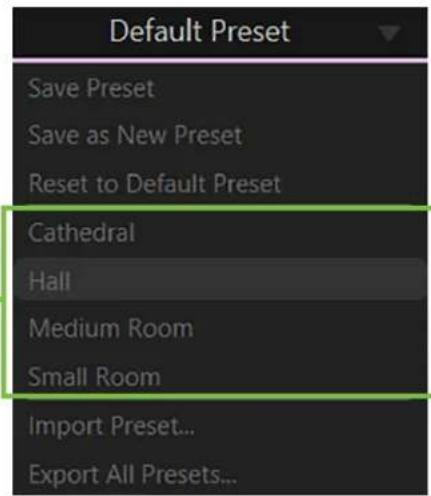
The number of user presets available is limited only by the available space on the computer (since presets are stored on the computer)... so basically unlimited. Presets are generally set ahead of time, not as a livestream or other event is taking place.
User presets are created by following the steps listed below:
- Click on 'Default Preset' to open a popover, as seen above and to the left.
- Click on 'Save Preset' or 'Save as New Preset'.

The difference between 'Save Preset' and 'Save as New Preset' is that the former will OVERRIDE any current parameters (of the selected channel), but the latter will save the changes under a new preset rather than copying over the currently selected preset.
Go ahead and create (and save / rename) some presets.
- Different audio sources call for different parameters. Feel free to add FX to the input channels at your discretion.
Now that we have discussed saving M-VOICE user presets, it is time to chat about the other preset selections and what they do.
Reset to Default Preset - Selecting this will reset the selected channel's M-FX to its default state. You'll hear the changes immediately and notice the changes to the parameters, as well.
'Reset to Default Preset' may only be recalled/loaded.

User Presets - As mentioned on the previous page, when user presets are created and saved, clicking on any one of the them loads that preset on to the open channel's M-FX. All appropriate parameters change to match the stored preset. After tapping it, you'll hear the changes immediately and notice the changes to the parameters, as well.
Now, if you simply hover over one of the user presets – without clicking on it – three circles appear on the right-hand side of the selected preset with three options:
Delete - The delete button deletes the currently selected M-FX preset.

Please be careful!!
When an M-FX preset is deleted, all currently set parameters will be deleted (with no undo), and there is no confirmation dialog to help prevent accidents.
Rename - When rename is chosen, use the keyboard to rename the currently selected M-FX preset.
Export - When an M-FX preset is selected, you are granted the option of exporting it to the computer's hard drive, an attached thumb drive, portable disk, or other. Just remember where it was exported!
If the file already exists in the location that you're trying to export it to, you will be prompted to answer the following question: "Do you want to replace it?" The choice, of course, is yours.


The three possibilities listed above are for single M-FX presets. But what if you want to import a preset and/or export all presets? Let's take a look...
Import Preset... - Importing M-FX presets is simple. After clicking on 'Import Preset...', find and select the desired preset(s).
Export All Presets... - Regardless of what M-FX preset is selected, you are granted the option of exporting ALL of them (simultaneously) to the computer's hard drive, an attached thumb drive, portable disk, or other. Just remember where they were exported!
If any of the files already exist in the location that you're trying to export them to, you will be prompted to answer if you want to replace it.

IMPORTANT - DO NOT FORGET! M-EQ presets are also available on the OUTPUT!
Appendix A : Service Information
Troubleshooting
If you think your Mackie product has a problem, please check out the following troubleshooting tips and do your best to confirm the problem. Visit the Support section of our website (www.mackie.com) to get some ideas or contact our technical support heroes.
Here are some useful tips that could correct any of the issues outlined below (or possibly any other issue that we haven't yet discovered).
As you might imagine, there are no user serviceable parts. If none of these tips listed below work, please contact our Technical Support heroes.
- Does a "Please Connect a Mackie MainStream device to continue" message appear on the display? Mackie Matrix will not work without a Mackie MainStream device connected to it. If already connected, remove then re-connect.
- Does Mackie Matrix fail to detect the MainStream device? Try connecting the MainStream device to the PC. If already connected, remove then re-connect.
- Does a "Cannot start more than 1 instance of App" message appear on the display? If the app is already open and running, this error message will appear.
- Does a hardware input have red text and the fader is locked (as seen to the left)? This means that the hardware has likely been unplugged from Mackie Matrix. Re-connect!
Sometimes words just aren't enough. As a writer, that makes me sad, but I also have a wife who is more of a 'watcher' than a 'reader' and perhaps that is you, as well. If you're more of a 'watching videos' person and 'reading comprehension really isn't my thang', then please check out a video we made while I go cry in the other room...
- Mackie MainStream & Matrix: Setting Up Your Audio in OBS for Live Streaming
- Last gasp before contacting Technical Support. Since Mackie Matrix works in conjunction with the Mackie MainStream, we would strongly advise you to please read and review that owner's manual, as well. Thank you!
- Please email or call Technical Support if you are having any other issue not listed here:
o mackie.com/support-contact
0 1-800-898-3211

About
Part Number, Rev, Version, and Date: SW1454, Rev A, Version 1.1.30, November 2024
Need help with MainStream and/or Matrix?
- Visit www.mackie.com/support to find: FAQs, manuals, addendums, and other documents.
- Email us at: www.mackie.com/support-contact
- Telephone 1-800-898-3211 to speak with one of our splendid technical support chaps (Monday through Friday, normal business hours, Pacific Time).
LOUD Audio, LLC. is always striving to improve our products by incorporating new and improved materials, components, and manufacturing methods. Therefore, we reserve the right to change these specifications at any time without notice. The "Running Man" is a registered trademark of LOUD Audio, LLC. All other brand names mentioned are trademarks or registered trademarks of their respective holders, and are hereby acknowledged.
Please check our website for any updates to this Owner's Manual: www.mackie.com. ©2024 LOUD Audio, LLC. All right All right All rights reserved.

natural_image
Symbolic icon of a running person inside a circle, no text or numbers present19820 North Creek Parkway #201, Bothell, WA 98011 • USA
Phone: 425.487.4333 • Toll-free: 800.898.321
Fax: 425.487.4337 • www.mackie.com

MACKIE.


- MACKIEMATRIX
- OWNER'S MANUAL V1.1.30
- Table of Contents
- Chapter 3 : Mixing....14
- Introduction....14
- Input Channels....15
- Sampler Channel 16
- Output Level 17
- Current Mix 18
- Mix Effects 19
- Stream Destination....19
- Virtual Device Channel Routing....20
- Menu 21
- Chapter 4 : M-VOICE ...... 24
- Introduction....24
- Easy Control Mode 25
- Parameter Setup - EQ (Easy) 28
- Pro Control Mode 34
- Parameter Setup - EQ (Pro) 36
- Chapter 5: M-FX....47
- Introduction......47
- Atomizer Reverb 47
- Chapter 6 : Samples....50
- Introduction....50
- Sampler Channel 50
- Play Sample 51
- Bank Switching....51
- Pad Customization 52
- Chapter 7: Presets....56
- Introduction......56
- Factory Presets vs User Presets 56
- DSP Presets....58
- Appendix A : Service Information....62
- Troubleshooting....62
- Chapter 1: Welcome
- Introduction
- Features
- About This Guide
- Chapter 2: Mixer Setup
- Applying Audio Sources to the Mixer
- Editing Inputs
- Mixer Setup
- Input Channels
- Channel Faders and Input Meters
- M-VOICE
- M-FX
- SOLO
- MUTE
- Sampler Channel
- Sampler Channel Fader
- Sample Pads
- Output Level
- Main Output Fader and Meters
- Current Mix
- Mix Effects
- Stream Destination
- Virtual Device Channel Routing
- App volume and device preferences
- Menu
- Easy Control Mode
- Parameter Setup - EQ (Easy)
- Parameter Setup - Gate (Easy)
- Parameter Setup - Compressor (Easy)
- Parameter Setup - De-Esser (Easy)
- Pro Control Mode
- Parameter Setup - EQ (Pro)
- EQ Gain, Frequency, Q [Bandwidth], and Shelf/Bell
- EQ Band 1
- EQ Band 2
- EQ Band 3
- EQ Band 4
- EQ Band 5
- RTA
- Parameter Setup - Gate (Pro)
- Parameter Setup - Compressor (Pro)
- Parameter Setup - De-Esser (Pro)
- Chapter 5: M-FX
- Atomizer Reverb
- ChronoTronic Delay
- Telephone
- StreamFX Voice Changer
- Chapter 6 : Samples
- Play Sample
- Bank Switching
- Pad Customization
- Chapter 7: Presets
- Factory Presets vs User Presets
- DSP Presets
- COMPRESSOR PRESETS DE-ESSER PRESETS
- Please be careful!!
- Appendix A : Service Information
- Troubleshooting
- About
- Need help with MainStream and/or Matrix?
Brand : MACKIE
Model : MainStream
Category : Audio software