
SRT 6010 - Satellite receiver STRONG - Free user manual and instructions
Find the device manual for free SRT 6010 STRONG in PDF.
| Product type | Digital satellite receiver |
| Brand | STRONG |
| Model | SRT 6010 |
| Input frequency | 950 ~ 2150 MHz |
| Input impedance | 75 Ω |
| Input level | -65 dBm ~ -25 dBm |
| LNB supply | 13/18 V ± 0.5 V, 500 mA max. |
| Modulation | QPSK |
| Symbol Rate | 2-45 MS/s |
| Video decoder | MPEG-2 MP@ML, resolution 720 × 576 (PAL) / 720 × 480 (NTSC) |
| Audio decoder | MPEG/MusiCam layer I & II, stereo, mono |
| Connectors | SCART TV, SCART VCR, S/PDIF coaxial, RS-232, S-VHS (model SRT 6015), RF modulator (model SRT 6015) |
| Flash memory | 16 Mbits |
| RAM (SDRAM) | 64 Mbits |
| Processor | 50 MHz |
| Power supply | 90-240 V AC, 50/60 Hz ± 5%, max. 20 W, standby ≤ 8 W |
| Main functions | EPG, teletext, parental control, timer, 9-image mosaic, DiSEqC 1.0/1.2, OTA update, Tetris game |
| Supplied accessories | Remote control, 2 AAA batteries, user manual |
| Maintenance and cleaning | Unplug before cleaning; use a soft cloth dampened with a mild soap solution; do not use alcohol or ammonia |
| Safety | Do not open the casing; avoid moisture and heat; unplug if not used for a long time; only use a power cord in good condition |
| Storage | Keep in original packaging, protected from shocks and moisture |
Frequently Asked Questions - SRT 6010 STRONG
User questions about SRT 6010 STRONG
0 question about this device. Answer the ones you know or ask your own.
Ask a new question about this device
Download the instructions for your Satellite receiver in PDF format for free! Find your manual SRT 6010 - STRONG and take your electronic device back in hand. On this page are published all the documents necessary for the use of your device. SRT 6010 by STRONG.
USER MANUAL SRT 6010 STRONG
PART 6 Environmental Issues
Content
1.0 Introduction 3
1.1 Safety Instructions 3
1.2 Features & Accessories 4
1.3 Safety Precautions 5
1.4 Storage 5
1.5 Equipment Set-up 6
2.0 Your Receiver 6
2.1 Front Panel 6
2.2 Remote Control Unit 7
2.3 Rear Panel 8
3.0 Connections 10
3.1 Connecting to TV & VCR 10
3.2 Connecting to Digital Audio Amplifier 11
3.3 Connecting to Satellite Dish 11
3.4 Connecting to serial cable for downloading software 13
4.0 Starting up 14
5.0 Main Menu 18
5.1 Channel Organiser 19
5.2 Installation 23
5.3 System setting 29
5.4 Timer 39
5.5 Game 40
6.0 Other operation functions 42
6.1 System Information 42
6.2 Mosaic (Nine picture view) 42
6.3 EPG (Electronic Program Guide) 43
6.4 Selection Audio Language 45
6.5 Teletext function 45
A.1 Trouble Shooting 47
A.2 Specifications 48
A.3 Glossary of Terms 50
1.0 Introduction
1.1 Safety Instructions
DO NOT INSTALL YOUR RECEIVER:
In a closed or poorly ventilated cabinet;
Directly on top of or under any another equipment;
On a surface which might obstruct the ventilation slots.
DO NOT EXPOSE THE RECEIVER OR ITS ACCESSORIES:
To direct sunlight or near any other equipment that generates heat;
To rain or intense moisture;
To any shock which may cause permanent damage to your receiver;
To any magnetic objects, such as loudspeakers, transformers, etc.;
To intense vibration;
- Never open the cover. It is dangerous to touch the inside of the receiver due to high voltage currents and possible electrical hazards. Your warranty will be void if the receiver has been opened.
- When the receiver is not used for a long period of time, you should unplug the power cord from the wall socket.
- Do not use a damaged power cord. It may cause a fire or an electrical shock.
- Do not touch a power cord with wet hands. It may cause an electric shock.
Place the receiver in a well-ventilated environment.
- When you are connecting the cables, be sure that the receiver is disconnected from the mains supply voltage.
- Do not use your receiver in a humid environment.
Make sure you read this user manual before installing your receiver.
How to Use This Manual
This manual provides complete instructions for installing and using this receiver.
The following symbols will serve as follow.

Warning
Indicates warning information.

Tips
Indicates any other additional important or helpful information.
MENUR eprects a button on the remote control or the receiver (Bold Character)
Move to Represents a menu item within a window. (Italic Character)
1.2 Features & Accessories
For all digital Free-To-Air TV and Radio programmes via satellite
Display showing channel number or time
Digital sound through coaxial output (S/PDIF)
Separate power switch
Set-up supports for first time installation
3200 channel memory capacity for 64 satellites
4 Favourite lists for TV-and Radio programme
Quick and easy installation & user-friendly menu
Excellent Audio & Video quality
Parental lock function for menu and selectable per channel
Teletext via OSD & VBI
Supports DiSEqC 1.0 and DiSEqC 1.2
Electronic Programme Guide (EPG) for present/following event information and up to 7 days for on screen programme information
Full multi-lingual DVB subtitling and audio track support
Multi-lingual support on screen menu (OSD): English, German, French, Italian, Spanish, Turkish, Bulgarian, Czech
Edit functions for TV or Radio programme name and satellite name
Future-proof: Software update via satellite (OTA)
Signal strength bar for digital transponders
Automatic, Network and manual channel scan options
Power on with last viewed channel
10 Timer for recording and/ or sleep-timer with 3 modes (daily, weekly, once)
Game (Tetris)
User-friendly remote control with coloured function buttons
Low power consumption
Advanced timer function
Mosaic function: 9 TV Channel in overview
Automatic clock change: summer/ winter time
S-VHS Connector
Multi norm UHF modulator Ch 21~69 (Pal BG - I - DK - MN)
Accessories:
User's Manual
1 Remote control unit
2x Batteries (AAA type)
Note: The batteries should not be recharged, disassembled, electrically short-circuited or be mixed or used with other types of batteries.
1.3 Safety Precautions
To maintain your receiver's optimum performance, you are advised to apply the following safety precautions:
Read this manual carefully and make sure you fully understand the instructions given.
Refer all maintenance or servicing to suitably qualified personnel
If you wish, you may clean your receiver with a soft lint-free cloth slightly made damp with a mild soap solution, only after disconnecting from the mains voltage supply.
- Do not use alcohol or ammonia based liquids to clean the receiver.
- Do not open the receiver cover, as you will be exposed to a shock hazard
Do not open the receiver cover this will void your warranty.
- Do not place any objects on top of the receiver because this might prevent proper cooling of the components inside.
- Make sure no foreign objects fall through the ventilation slots because this could cause fire or an electric shock.
Wait a few seconds after switching off the receiver before you move the receiver or disconnect any equipment.
Please ensure that the electrical power supply corresponds with the voltage on the electrical identification plate at the back of the receiver.
It is a necessity that you only use an approved extension and compatible wiring that is suitable for the electrical power consumption of the installed equipment.
If the receiver does not operate normally even after strictly following the instructions in this user manual, it is recommended to consult your dealer.
1.4 Storage
Your receiver and its accessories are stored and delivered in a packaging designed to protect against electric shocks and moisture. When unpacking it, make sure that all the parts are included and keep the packaging away from children. When transporting the receiver from one place to another or if you are returning it under warranty make sure to repack the receiver in its original packaging with its accessories. Failing to comply with such packaging procedures could void your warranty.
1.5 Equipment Set-up
We recommend you consult a professional installer to set up your equipment. Otherwise, please follow the instructions below:
Refer to the user manual of your TV and your antenna.
Make sure that the SCART cable is in a good condition.
Make sure that the SCART cable connections are well shielded
Make sure that the outdoor components of the antenna are in good condition.
2.0 Your Receiver
2.1 Front Panel
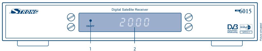
FIGURE 1. Front Panel
1. Mode indicator
The RED light indicates that the receiver is in STAND-BY mode. The GREEN light indicates that the receiver is in AWAKE mode.
2. 4 digits display
In STAND-BY mode this indicates current time In AWAKE mode this indicates current channel number
1 Only for model SRT 6010 and 6015
2.2 Remote Control Unit
All features of the set-top box can be controlled with the remote control unit.
A. Turns the receiver On/Off.
B. Mutes audio output of the receiver.
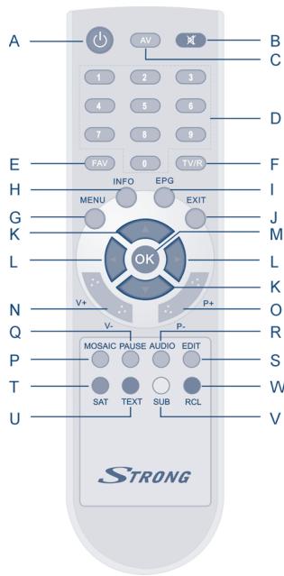
FIGURE 2.
Remote Control Unit
C. AV
Toggle between TV and AV mode.
D. 0~9
Changes channel and controls numeric functions.
E. FAV
Toggle Favorite mode ON / OFF.
F. TV/R
Toggle between TV or RADIO mode.
G.MENU
Shows the main menu and exits from any level of menu to view mode.
H. INFO
Shows information of the current channel.
I. EPG
Shows the EPG (Electronic Program Guide) only when menu is off.
J. EXIT
Exits from the menu or sub-menu and cancels the progressing function if applicable.
K. ▲▼
Change the current program to the previous/next program when menu is off. Moves the cursor to upward/downward when menu is on.
L. 4
Increases/decreases the volume level when menu is off. Change the setting values in specific Menu item when menu is on.
M. OK
Activates the highlighted menu item. Displays a channel list according to TV /Radio Mode.
N. V+ / V
Use to increase or decrease the receiver volume level.
O. P_+ / P_-
Page up and down in menu list.
P. Mosaic
Show pictures of 9 channels on the screen simultaneously
Q. PAUSE
Freeze/Resume picture.
R.AUDIO
Shows the list of available audio languages for the channel you are watching. In addition it sets the current channel audio to stereo () , left-mono ( or right-mono ) .
S.EDIT
Program edit
T.SAT
Switch the satellite
U. TEXT
Shows current service's Teletext on OSD
V. SUB
Show the list of subtitled languages the current channel supports.
W. RECALL
Switches back to last channel viewed
2.3 Rear Panel
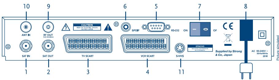
FIGURE 3. Rear Panel
1. SAT IN
Connect the digital signal from your LNB on the satellite dish to this connector.
2. SAT OUT
Givest you the possibility to connect an extra receiver (analogue or digital).
3. TV SCART Connector
To connect your receiver to your TV set using a SCART cable.
4. VCR SCART Connector
To connect your receiver to your video recorder using a scart cable. Your video signal will now be looped through your receiver to your TV set.
5. RS-232 Serial Port
This serial port can be used to connect your PC with your receiver, to download new versions of software to your receiver.
6. S/PDIF Digital audio output
Use this coaxial output to connect your receiver to the input of your digital audio amplifier.
7. Power ON/OFF Switch
8. Power Cord
Your receiver requires a current of 90 240 ~V AC (Auto-selectable), 50 60 ~Hz + / - 5% .
Make sure to check the power specification before connecting your receiver to the wall outlet.
9. RF OUT Incl. modulator
RF Modulator output (male part). If you do not use a scart cable to connect your receiver to your TV, or if you have connected a cable to the ANT input, you will have to use this connector to connect the receiver to your TV by using a coaxial cable. You can also use this connector to connect a second TV set to your receiver.
10. ANT IN
Input Antenna (female part). If you have cable TV or if you have an outdoor antenna, then you can connect the RF cable coming from the antenna or wall connector to this ANT input.
11. S-VHS
Use this connector to connect your receiver to your TV or VCR using S-Video cable for better picture quality.
1 Only for model SRT 6010 and 6015
2 Only for model SRT 6015
3.0 Connections
3.1 Connecting to TV & VCR
- Connect the satellite signal from the LNB to the SAT IN connector.
- Connect a UHF coaxial lead coming from your Cable TV or Outdoor Antenna to the ANT input connector at the back of the receiver.
- Connect a coaxial cable to the RF OUT connector at the back of the receiver.
- Connect the other end of this coaxial cable to the ANT IN connector of your TV set.
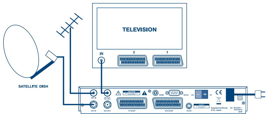
FIGURE 4. Basic connection with a Scart cable
- Connect the satellite signal from the LNB to the SAT IN connector.
- Connect the TV scart connector at the back of the receiver to the scart-in connector on your TV set.
- Connect the VCR scart connector at the back of the receiver to the scart-in connector on your VCR.
1 Only for model SRT 6015
2 Only for model SRT 6010 and 6015
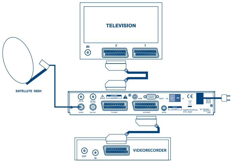
FIGURE 5. Advanced connection of the receiver to the TV set and VCR
3.2 Connecting to Digital Audio Amplifier and to TV-set with S-VHS connection.
The Digital Audio Amplifier is connected with the receiver from the S/PDIF connector. The TV-set is connected with the receiver on both S-VHS connectors.
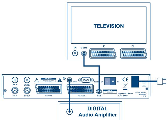
FIGURE 6
3.3 Connecting to Satellite Dish
First choose which satellite you want to receive your signals from, and have your dealer aim your dish at the requested satellite.
Connect a coax cable to your LNB and the other end directly to the SAT IN connector of your receiver.
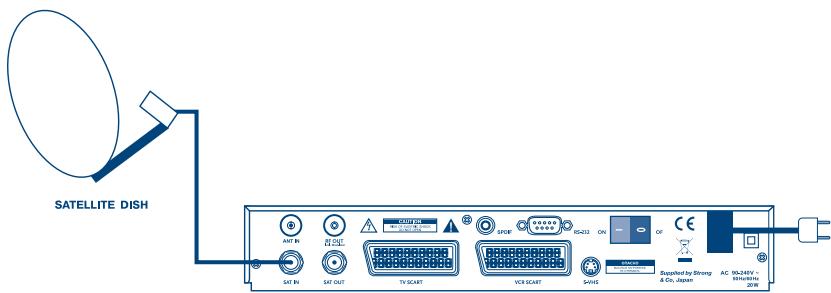
FIGURE 7. Connecting a fixed satellite dish to your receiver
If you want to watch programs from more than one satellite (For example from Astra and from Hot Bird) it is advisable to use fixed dishes and a DiSEqC 1.0 switch. Have your Dealer aim the dishes at the requested satellites and connect the LNB's with coax cables to the IN connectors of the DiSEqC 1.0 switch . Connect the OUT connector of the DiSEqC 1.0 switch to the SAT IN connector at the back of your receiver.
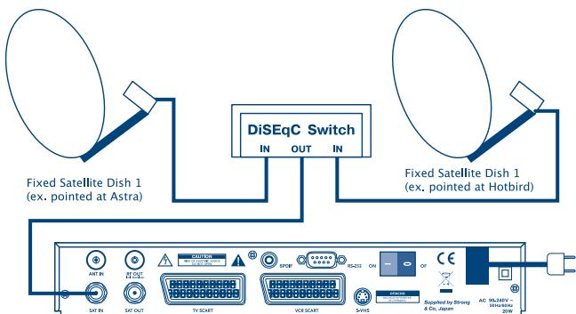
FIGURE 8. Connecting multiple fixed dishes to your receiver using a DiSEqC 1.0 switch
Another possibility for watching programs from multiple satellites is by mounting
a dish to a motorized DiSEqC 1.2 positioner.
Have your dealer mount the dish to the positioner, set the correct angle of the elevation and let him set the center point for your positioner.
Connect the LNB with a coax cable to the SAT IN connector of the positioner, and connect the OUT connector of the positioner to the SAT IN connector at the back of your receiver.
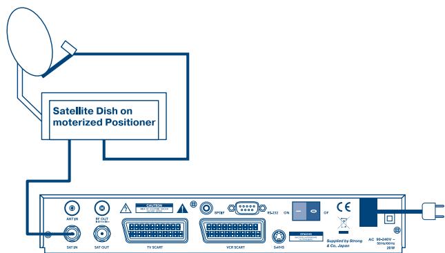
FIGURE 9. Connecting a dish on a motorized positioner to your receiver
3.4 Connecting to serial cable for downloading software
- Connect the RS 232 connector on the back of your receiver to the Serial port of your computer using a serial cable.
- Instructions how to download software can be found on our website www,strongsat.com (support > download). However, this receiver can download new system software automatically by satellite.
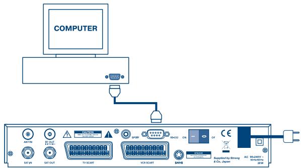
FIGURE 10. Connecting the RS-232 connector on the back of your receiver to the Serial port
4.0 Starting up
Ensure that your satellite receiver is correctly connected to your television and dish, and that your satellite signal is of good quality. (If you are not sure about this then ask your local strong dealer to check your installation or satellite signal.)
Confirm that the power plug on the receiver is plugged into the wall outlet. Turn on the receiver. The following picture is shown the first time you switch on the receiver.

SCREEN 1
It is recommended that you perform the first time installation following the Installation Wizard step by step. It will help you to easily achieve system configuration and channel installation. If you are a professional installer then you can skip wizard by pressing MENU button and set-up channels using the Installation menu. Press UP/DOWN to choose your language, press OK to confirm. The select satellite menu will appear as below.
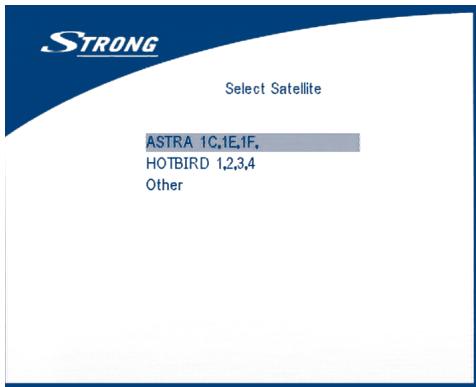
SCREEN 2
Future installation steps are depend from satellite where your dish is aimed.
- Your dish is aimed to Astra 1C, 1E, 1F or Hotbird satellite.
Press UP/DOWN to select the ASTRA or Hotbird satellite and press OK button on your remote control. Below screen will appear.
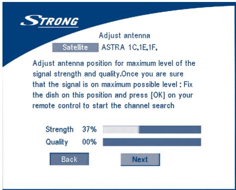
SCREEN 3
Follow instruction written on screen. When you have fixed your dish at correct direction choose NEXT and press the OK button. The channel Setup menu will appear as shown on screen 8.
- Your dish is aimed at another satellite, select "Other" in "Select satellite" menu and press OK, more satellite will appear in the satellite list, you can select the satellite you want.
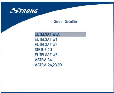
SCREEN 4
If you select a satellite in the satellite list, the configure antenna menu will appear, please set the LNB Type, LNB Low Freq, LNB High Freq, Band control, Polarisation control, DiSEqC Switch and Antenna mode.
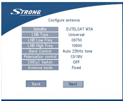
SCREEN 5
2a. If you have a fixed dish then set "Antenna mode" to "Fixed", select NEXT and press the OK button. The Adjust antenna screen as shown on screen 6 will appear. You should select transponder receivable at your location, adjust the antenna position for maximum level for the signal strength and quality.
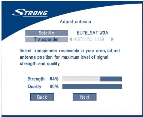
SCREEN 6
When you have completed the adjustment, choose NEXT and press the OK button. The channel Setup menu will appear as shown on screen 8.
2b. If you have a DiSEqC Dish, you can set "Antenna mode" to DiSEqC 1..2, choose NEXT and press the OK button. The menu Adjust antenna will appear as shown on screen 7.
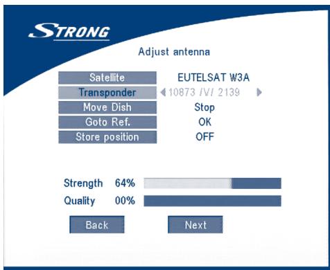
SCREEN 7
You should select transponder receivable at your location (choose "Transponder" field and select transponder by pressing LEFT/RIGHT button). Then choose field "Move Dish" and adjust position of the dish by pressing the LEFT/RIGHT button. Once you adjust the dish position choose "Store position", set number of the position by pressing LEFT/RIGHT button. Then choose NEXT and press the OK button. You will be guided to Channel Setup menu as shown on screen 8 below.
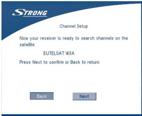
SCREEN 8
Choose NEXT and press the OK button to start the scan.
When the scan is completed, the receiver will save the services information automatically and exit to the normal play state.
5.0 Main Menu
All the important settings and features of your receiver can be operated in Main Menu. The Main Menu consists of five sub-menus which are "Channel Organizer", "Installation", "System setting", "Timer" and "Game".
Press the MENU key when the menu is off, The MAIN MENU screen will appear (SCREEN 9).

SCREEN 9
5.1 Channel Organiser
In the MAIN MENU screen, press UP/DOWN to move the cursor to Channel Organiser, and then press OK to enter the Channel Organiser menu.
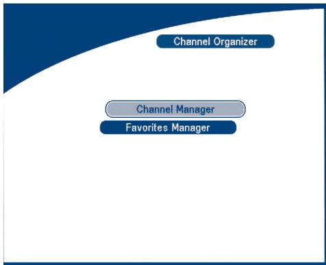
SCREEN 10
The Channel Organiser menu consists of two sub-menus; "Channel Manager" and "Favorite Manager".
5.1.1 Channel Manager
In this menu, you can change the order of the channels, move, delete and edit channels.
To change the satellite use the RED button.
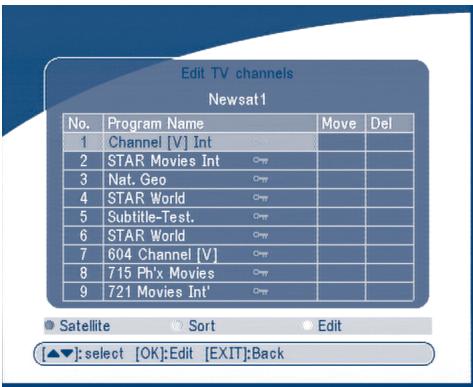
SCREEN 11
Sort (GREEN buton)
You can sort the channel order in the channel list by "name a z ", "name z a ", "Free-CA",
"Fav - NO Fav" or Default type.
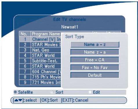
SCREEN 12
Edit (YELLOW button)
Select the channel that you wish to edit, press the YELLOW (Edit) button to move into the modify program menu. (SCREEN 13) In this menu, you can modify the Program Name, Down Frequency, Symbol rate, Video PID, Audio PID.
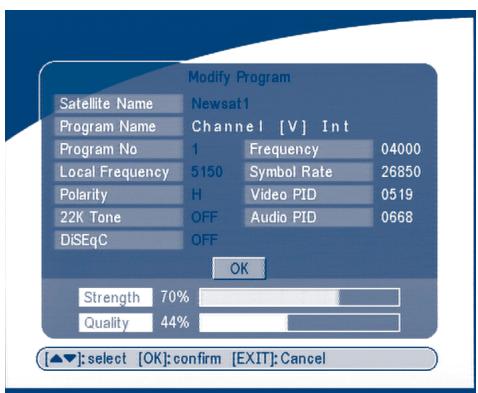
SCREEN 13
If you want to rename the channel, use the UP/DOWN keys to select "Program Name" and press OK, the program name dialog will shown as below.
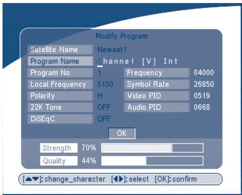
SCREEN 14
Use the LEFT/RIGHT button to move the cursor to the character you wish to edit. Use the UP/DOWN button to change character (scroll alphabet). If you wish to delete character you have to replace it with "space" character.
When editing is complete, press the OK button.
Move channel
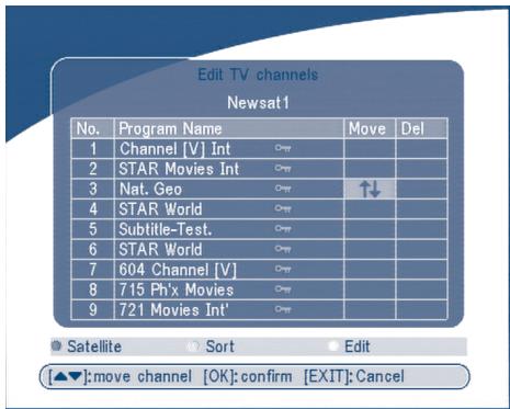
SCREEN 15
Press the UP/DOWN keys to point the focus of the menu to the channel of your selection.
Press the LEFT/RIGHT keys to point the focus of the menu to the column "Move".
When the focus is on column "Move", press the OK button to confirm selection of the channel, using the UP/DOWN buttons move the channel to its new location and press the OK button to confirm the new location. Repeat this for every channel that you want to move.
Delete channel
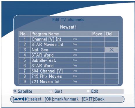
SCREEN 16
Press the UP/DOWN keys to point the focus of the menu to the channel of your selection.
Press the LEFT/RIGHT keys to point the focus of the menu to the column "Del".
When the focus is on column "Del", press the OK button to mark the channel as selected to be deleted from the list. To apply the changes press the EXIT button and confirm the channel's deletion.
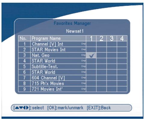
5.1.2 Favorites Manager
Press the UP/DOWN keys to select the channel. Press the LEFT/RIGHT keys to point the focus to the favorite group. Press the OK button to add the selected channel to the Favorite group. To remove the channel from the favorite group, repeat same operation.
SCREEN 17
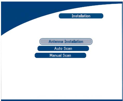
5.2 Installation
The installation menu contains three sub-menus; "Antenna Installation", "Auto Scan" and "Manual Scan".
SCREEN 18
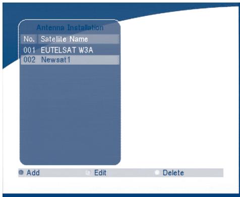
5.2.1 Antenna Installation
You can add a satellite, edit a satellite and delete a satellite in this menu.
SCREEN 19
Add satellite
If you want add a new satellite, press the RED key in this menu, a satellite list will appear on the screen.
Press RIGHT/LEFT to select the satellite.
If the satellite does not exist in the satellite list, please select "NEW SAT1".
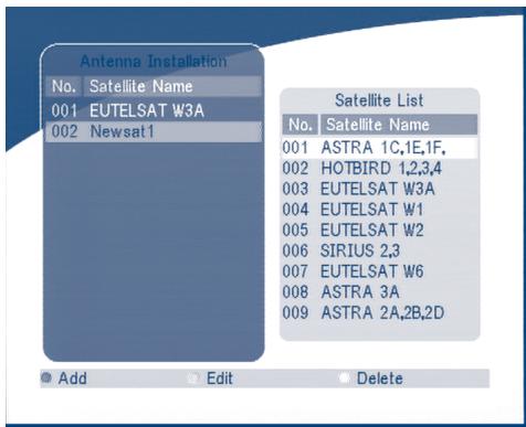
SCREEN 20
Edit satellite
If the parameters of the satellite were changed or the satellite is a new satellite, you must set the parameters of the satellite, such as LNB type, LNB low Freq, LNB High Freq, Transponder, LNB Power, 22 k Tone, DiSEqC and Motor Position.
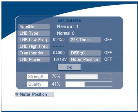
SCREEN 21
Delete satellite
If you want to delete a satellite, press the YELLOW key. Then warning message will appear as below.
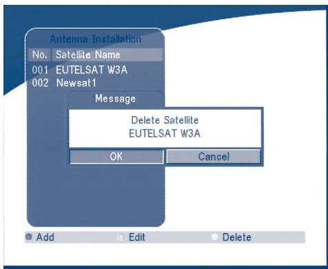
SCREEN 22
Select OK and press the OK key to confirm.
5.2.2 Auto Scan
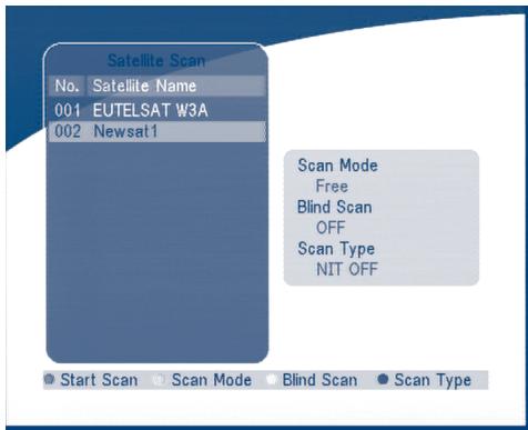
SCREEN 23
Press the GREEN key to set the scan mode to Free or Free+CA.
Press the YELLOW Key to set the Blind Scan to ON or OFF.
Press the BLUE Key to set the scan type to NIT OFF or NIT ON.
When the set-up is completed, press the RED key to start the scan, shown as below.
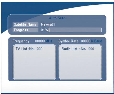
SCREEN 24
5.2.3 Manual Scan
In this menu, you can add a new transponder, edit the transponder or delete the transponder. And you can scan transponder. User can switch satellites with the RED button.
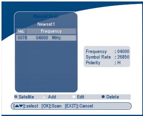
SCREEN 25
Add Transponder:
In this menu, you can add a new transponder to the system. Press the GREEN button, the Add Transponder sub-menu will appear on screen.
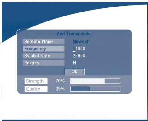
SCREEN 26
Down Frequency:
Symbol Rate:
Polarity:
Input the frequency of the new transponder.
Input the symbol rate of the new transponder.
Select the Polarity of the new transponder.
Edit Transponder:
In this menu, you can edit a transponder in the system. Press the YELLOW button, the Edit Transponder sub-menu will appear on screen.
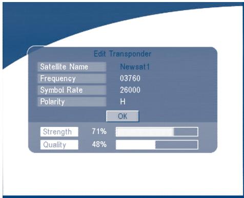
SCREEN 27
Delete Transponder
Press the BLUE button to delete a transponder. The warning massage will be shown as below.
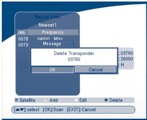
SCREEN 28
Press LEFT/RIGHT to select OK, press the OK button to confirm.
Scan
Press UP/DOWN to select a transponder, press the OK button to scan all the channels on the transponder.
5.3 System setting
In this menu, you can configure the systems such as language Setting, OSD style, Parental Control, TV Settings and Time Setting.
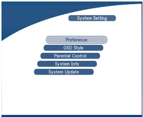
SCREEN 29
5.3.1 Preference
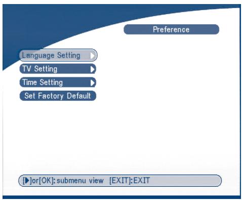
SCREEN 30
5.3.1.1 Language Setting
You can change the language of the OSD and Audio.
Press UP/DOWN to select the OSD language or Audio language. Press OK/RIGHT to enter the language list and Press UP/DOWN to select the language. Press OK to confirm.

SCREEN 31
5.3.1.2 TV settings
You can set the TV mode, Screen mode and Video output.
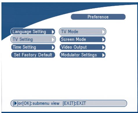
SCREEN 32
TV mode
The TV mode Screen will appear as follows:

SCREEN 33
Press OK/RIGHT to select PAL or NTSC, press OK to confirm. If you don't know which standard your TV has, please select AUTO.
Screen mode
The TV format Screen will appear as follows:
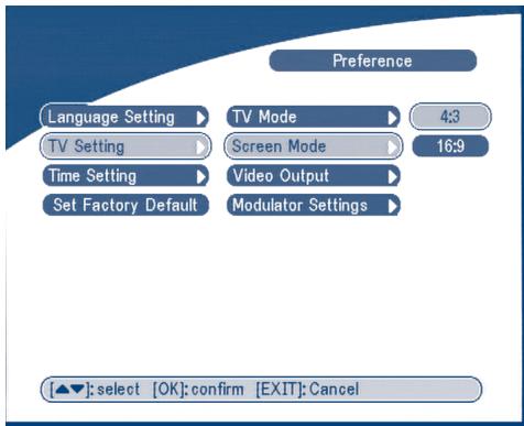
SCREEN 34
Press OK/RIGHT to select 4:3 or 16:9, press OK to confirm
Video output
The Video output Screen will appear as follows:
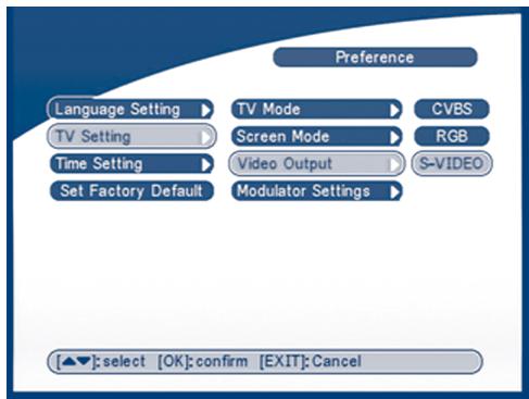
SCREEN 35
Press OK/RIGHT to select CVBS/ RGB or S-VIDEO, press OK to confirm.
Warning! If RGB is selected > SVHS output is switched OFF totally.
Note: S-Video mode available in the model SRT 6015 only.
Modulator Settings (only for model SRT 6015)
The Modulator Settings Screen will appear as follows:
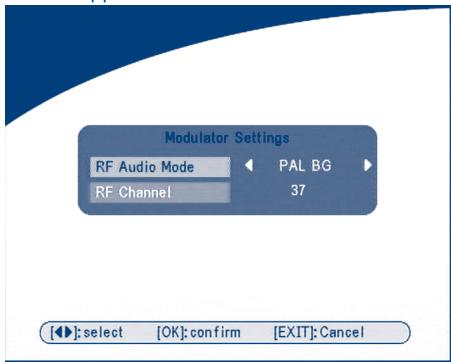
SCREEN 36
Press UP/DOWN to select RF Audio Mode or RF Channel. Use LEFT/RIGHT to set RF Audio Mode and RF Channel. Press OK to confirm.
5.3.1.3 Time Settings
If a broadcaster provides GMT, you can set the time using GMT, or set your own time by yourself. If the GMT usage is ON then the Current time is set automatically or you can set the time zone. If your broadcaster provides the correct time offset then your receiver will change from summertime to winter-time automatically.
If you set GMT Usage to OFF, Set Data and Set Time item are displayed.
To set the time value manually, move the cursor to the time item and use the numeric buttons on the remote control.
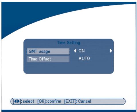
SCREEN 37
5.3.1.4 Set Factory Default
Please be careful when using this function, because it will erase all the data and parameters you may have set earlier to your receiver. Once you set the factory default you will have to re-install your preferences and re-scan your channels. To reset your receiver to factory default, apply the following steps:
Select Set Factory default and press OK. The warning message will appear as below.
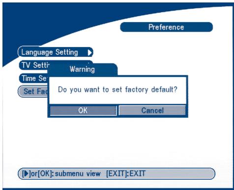
SCREEN 38
Select OK and press the OK key, the receiver will return to its factory default state, and all user data will be deleted.
Note: Your PIN code will change back to the factory setting "0000".
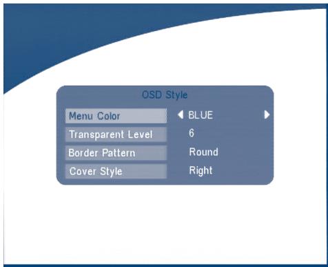
5.3.2 OSD Style
In this menu, you can set the Menu Colour, Transparency Level, Border Pattern and Cover Style.
SCREEN 39
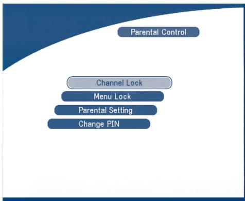
5.3.3 Parental Control
In this menu, you can set channel lock status (ON or OFF), the menu lock status, parental setting and change the PIN code (shown as SCREEN 40).
The default PIN code is 0000.
SCREEN 40
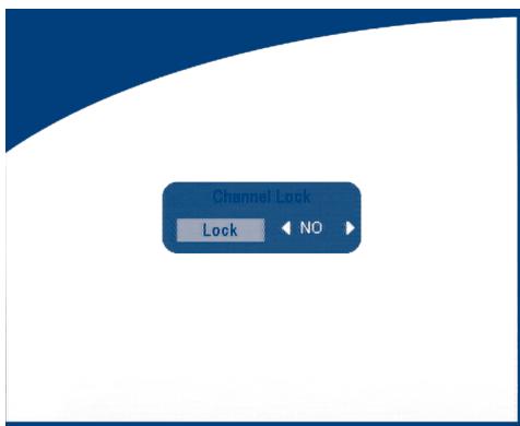
Channel Lock
Set the system channel lock to ON or OFF. If the channel lock is on, the user has to enter the parental PIN code correctly before watching the locked channel.
SCREEN 41
■ Menu Lock
Press OK to select whether you need the lock or not for the Menu, YES or NO, press OK to confirm. If the menu lock is on, then for some operations such as search program and set factory default, you need to enter your PIN.
Parental Setting
Set some channels to lock status. If a channel is locked, the user has to enter the parental PIN code correctly before watching the locked channel.
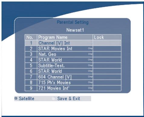
SCREEN 42
Use the UP/DOWN keys to select the channel you want to lock.
Press the OK button to lock the channel.
Change PIN
Modifying the PIN. You must enter the 4 digits PIN and confirm it again; the system PIN will be changed into the new PIN as show on SCREEN 42.
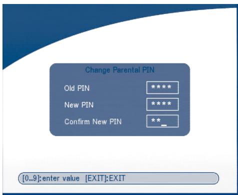
SCREEN 43
5.3.4 System info
The system information displays information about your receiver such as software and UI version.
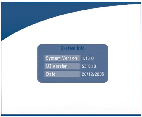
SCREEN 44
5.3.5 System Update
In this menu, you can select between "STB to STB" and "OAD"
STB to STB software transfer.
a) First power off both STBs, connect them with cross RS 232.
b) Then power on master STB (master is STB from which you will copy software) and keep slave STB off. Navigate in the menu of master STB and select "System Update - STB to STB".
c) When the status displays "Detecting slave STB", power on slave STB, after the master STB detects the slave, the master starts transmission and burns.
d) While transmitting and burning, it is very important to avoid other operations such as power off because this may cause destruction of the data in the FLASH memory and the receiver will need to be repaired.
e) When update is complete, first power off both STBs, then disconnect the RS 232 line.
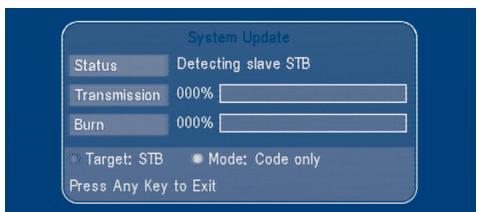
SCREEN 45
Over Air Download (OAD)
Select this option in order to update your receiver with the latest software version.
The receiver will check availability of the software update on air and load the latest software, if available. You will be asked to confirm update. Do not switch power off and do not disconnect the receiver from the aerial during update process.
Availability of the software update is subject of local broadcast condition and may not work in all countries. Contact your vendor to find out more about this function.
Update through PC to STB
- Connect Computer to receiver (receiver must be power off) with a 9-pin cross cable (two females)
- The computer will follow the steps below:
Start -> Programs -> Accessories -> Communications -> Hyper terminal
Then choose "COM1" or "COM2" according to which port you are using in the computer and port setting as follows:
Bits per Second: 115200
Data bits: 8
Parity: None
Stop bits: 1
Flow Control: None
- In Hyper Terminal menu select "transfer" item and then press "send file" item. Select the file with the new software (.UPD) you want to download and choose the protocol "1K Xmodem". Finally press ok and a download menu will appear in the computer screen. Power on the receiver, then the download process will begin.
- After about 2.5 minutes, the message "OK, Reset" will appear on the computer on Hyper Terminal window, which means the download has completed successfully.
- Power off the receiver and then unplug the RS 232 interface.
*Note: INCORRECT OPERATION MAY CAUSE UNREPAIRABLE DAMAGE TO THE RECEIVER.
- DO NOT POWER OFF THE RECEIVER DURING THE PROCESS OF DOWNLOAD.
- DO NOT PLUG IN OR UNPLUG THE RS232 INTERFACE WHEN RECEIVER IS POWERED ON.
5.4 Timer
You can set the timer to make the receiver perform designated actions including timer based wake up or sleep instructions to the set-top-box.
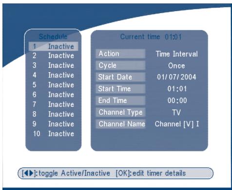
SCREEN 46
Use the UP/DOWN buttons to select timer. Press the LEFT/RIGHT key to activate/inactivate current timer. Press the OK button to enter your selected timer settings.
Action: You can select the following functions:
"Power On": The receiver powers on at the designated date and time.
"Time interval": The receiver switches on at the designated date and time, displays the channel and then switches off at the designated date and time (The value set at the end time).
"Power Off": The receiver powers off at the designated date and time.
Cycle: You can set the cycle of the action designated in the timer mode (one time, Daily or Weekly).
Start Date: You can set the start date of the timer action.
Start Time: You can set the start time of the timer action.
End Time: You can set the end time of the channel viewing when the Timer mode is on. Time Interval.
Channel Type: Select between TV and Radio.
Channel Name: Press the Right button to display the channel list and using the navigation buttons select the channel to be shown when the receiver will power on by the timer.
5.5 Game
The receiver has one game Tetris and a calendar. In this menu user can select any game item and press OK to play the game. Or you can press the GAME key in normal play state into the game menu directly.
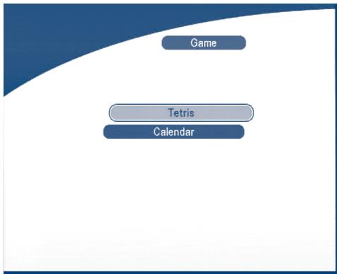
SCREEN 47
5.5.1 Tetris
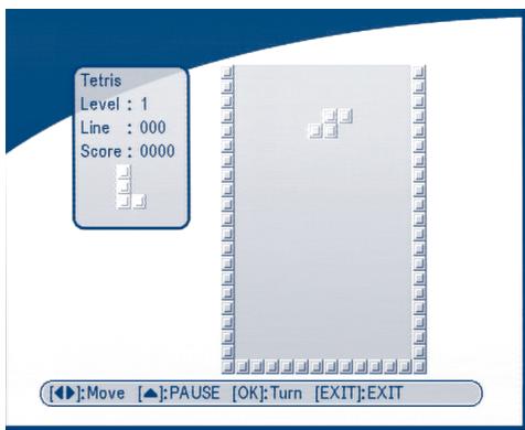
SCREEN 48
Key function:
LEFT/RIGHT key to move the block to left or right.
DOWN to drop the block.
UP to Rotate the block.
5.5.2 Calendar
UP/DOWN: + / - months.
LEFT/RIGHT: + / - years (range from 1900 to 2100).
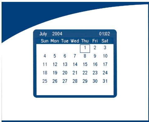
SCREEN 49
6.0 Other operation functions
6.1 System Information
In normal operation status (no menu operation), press the INFO button twice, the Program Information menu will appear on screen as show on
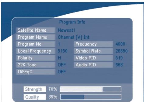
SCREEN 50
6.2 MOSAIC (Nine picture view)
In normal operation status (no menu operation), press the MOSAIC button, there are nine picture being showing on screen such as those on
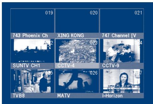
SCREEN 51
6.3 EPG (Electronic Program Guide)
The EPG shows the event information on the current TP channel by time zone.
With MENU off, press the EPG button. The EPG Menu will appear:
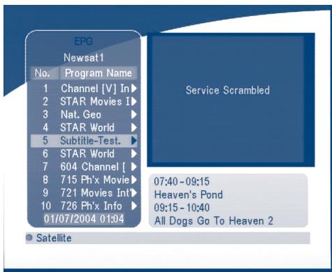
SCREEN 52
Press UP/DOWN to choose the channel.
Press RIGHT into EPG for schedules of the current channel.
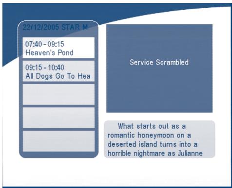
SCREEN 53
In EPG schedules menu:
Press the UP/DOWN keys to choose the schedule items.
Press P + / P- into next / previous day's schedules.
Press LEFT/EXIT to return to EPG Menu.
Press RIGHT to show the details of this item.
Heaven's Pond
22/12/2005 07:40-09:15
Description:
What starts out as a romantic honeymoon on a deserted island turns into a horrible nightmare as Juliette (Reid) discovers that her husband is, in fact, psychotic. Trapped on the island, he has no plans of ever returning to civilization
SCREEN 54
In EPG schedule details:
Press P + / P- into next/ previous page.
Press LEFT/EXIT to return to the EPG schedule Menu.
You can set up the event timer by pressing OK in the EPG schedule screen.
To set up an timer event:
- Press UP/DOWN to move the cursor to the event for which you want to add a timer.
- Press OK to add a timer.
SCREEN 54 shows you current event timer information based on the event you have chosen. You can also use this screen to modify each value. To save the settings, press OK. To quit event timer setup, press EXIT.
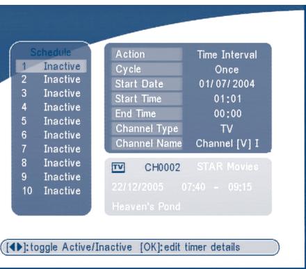
SCREEN 55
6.4 Selection Audio Language
Press the AUDIO button on the remote control to select the audio language as show in
Select the LEFT, RIGHT ,MIX or STEREO. press OK to make one selection.
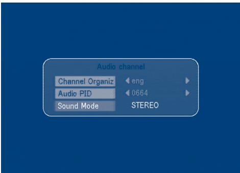
SCREEN 56
6.5 Teletext function
With menu off, press TEXT.

SCREEN 57
In TEXT on OSD:
Press UP/DOWN to add/ subtract displayed page number
Press the Numeric keys to input the page directly and
If current the program has no Teletext, the screen below will appear:
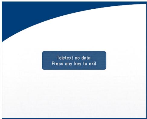
SCREEN 58
A.1 Trouble Shooting
There may be various reasons for the abnormal operation of the receiver.
Check the receiver according to the procedures shown below.
If the receiver does not work properly after checking it, please contact the dealer.
Don't open the receiver cover.
This may cause a dangerous situation.
| Symptom | Cause | Remedy |
| The display on front panel does not light up | The power cord is not plugged in. | Check that the power cord is plugged in to the wall outlet. |
| No picture or sound | Wrong connection of the Audio/Video output of the receiver to TV. | Connect the Audio/ Video output of the receiver to TV correctly. |
| Audio muting. | Press the Mute button | |
| TV power off. | Turn TV on. | |
| No picture | The receiver can't receive the signal | Check the antenna cable, replace the cable, or connect the cable to the receiver tightly. |
| Incorrect values of some tuner parameters. | Set the values of the tuner parameters correctly in the installation menu. | |
| Wrong direction of the dish | Check the signal strength with a spectrum analyzer and adjust your dish correctly. | |
| The remote control does not work | The batteries of the remote controller are not inserted or exhausted | Check whether the batteries are inserted correctly in your remote control. Check the batteries, and if exhausted replace the batteries in the remote control. |
A.2 Specifications
1. Tuner and demodulator
Input frequency 950~2150MHz
Input impedance 75 ohm
Input level -65 dBm ~ -25 dBm
LNB power supply 13 / 18V± 0.5V, Max 500 mA,
Waveform QPSK
Symbol rate 2-45 MS/s
Output mode Stereo,Joint Stereo,Dual Mono,Mono
Sampling frequency 32,44.1,48 kHz
Audio output 0.775 Vrms, Unbalanced
3. System and memory
CPU Speed 50 MHz
Flash memory 16 Mbits
SDRAM 64 Mbits
4. A/V & Data In/Out
TV Scart Output RGB, CVBS, Audio L/R Output with Volume Control
Input: CVBS, Audio L/R
Output: CVBS, Audio L/R Output with Volume Control
S/PDIF output Digital audio output, coaxial
Data Interface RS 232, Bit Rate: 115200 baud
Connector: 9-Pin D-Sub Male type
RF Modulator 2 UHF output channels CH21-69 selectable via menu
PAL B/G, D/K, M/N or I selectable
S-VHS output ^2 High video quality output.
Available in models SRT 6010 and SRT 6015
Available in model SRT 6015.
5. Power Supply
Input Voltage
90-240VAC,50/60Hz+/-5%
Power Consumption
Max. 20 W
Stand-by Power
< = 8 ~W
6. Physical Specification
7. Environmental Conditions
Operating Temperature
0 40^ C
Storage Temperature
-30°C ~ 80°C
Operating Humidity Range
10 85% RH, Non-condensing
Storage Humidity Range
5 ~ 90% RH, Non-condensing
A.3 Glossary of Terms
| C band | 3.7 ~ 4.2 GHz Frequency. |
| DiSEqC | Digital Satellite Equipment Control. |
| EPG | Electronic program guides that are transmitted by a broadcaster from a particular satellite to display information guide about a program content. |
| Fixed Dish | A dish antenna that is aimed at one particular satellite. |
| Free-To-Air broadcast | Unscrambled broadcast which you can view for free. |
| Ku band | 11 ~ 13 GHz Frequency. |
| LNB | (Low-Noise Block down-converter). The LNB is an electronic unit mounted on the satellite dish. It receives the signals reflected by the dish and converts them to signals that can be used by Satellite receiver. |
| MPEG | The Moving Picture Experts Group is founded by the ISO. MPEG is a standard method for digital transmission of video and audio. |
| Network | A network which is also known as a bouquet is a set of channels that is offered by a single broadcaster. |
| PAL | Referring to the Phase Alternate Line colour system adopted by European broadcasters. |
| Parental lock | This function gives you the possibility to 'lock' other several functions of the receiver to prevent unauthorized users such as children to view channels that are not suitable for them. A PIN code is required to use of the parental lock. |
| PID | The transmitted packages have identifiers (PID) that tells the receiver what to do with the received information. Satellite receivers normally use four types of PID, these are V-PID (video PID), A-PID (audio PID), P-PID (Program PID) and data PID (EPG information). |
PIN Code
Personal Identification NumberA four-digit code that is used for locking/unlocking, e.g. with the parental control feature.
Polarization
Allows several programmes to be fitted into the same frequency band. The signals from a satellite are transmitter either with linear (vertical or horizontal) polarization or circular (right or left) polarization.
RS 232
Serial data port.

Inhaltverzeichnis
N'EXPOSEZ PAS LE RÉCEPTEUR OU SES ACCESSOIRES:
1. SAT IN (SAT ENTREE)
Dimension (L x H x P) 260 x 40 x 140 mm
Poids 1.2 kg
NON ESPORRE IL RICEVITORE O I SUOI ACCESSORI:
2 Battery (pseudo AAA)
1. LED accensione/stand by

FIGURA 1. Panel Frontal
- Led encendido/stand by
A. Encendido/apagado (On/Off).
B. Silencio.
C. AV
Paso de TV a AV (Habilitita la entrada SCART VCR).
D. 0 9
Teclador numérico.
E. FAV
Symbol Rate 2-45 MS/s
DiSEqC Digital Satellite Equipment Control.
Environmental Issues
Strong is committed to reducing the impact of its products on the environment. To maximise the benefits of our design enhancements, your co-operation is required.
Electronic product recycling
Do not dispose of this product with your domestic rubbish.
At the end of its useful life, this product contains materials which when processed correctly can be recovered and recycled. By participating in the responsible recycling of this product you will be reducing the requirement for new raw materials and reducing the amount of material that would otherwise end up in landfill. When you purchase a new, similar product your retailer may offer to take this old one off you. Alternatively, you can take it to your local recycling centre. Your retailer or local municipal authority will advise you of the collection facilities available for waste electronically products in your area. User of this service will be free to you.
Within the scope of the European legislation on Waste Electrical and Electronic Equipment (Directive 2002/96/EC valid as of August 2005) STRONG provides a recycling system free of charge for consumers to returning products after end of life. For more information about STRONG's environmental policy to you:
www,strongsat.com - select "About us" and "Environmental Policy" from the submenu.

Packaging
When disposing of this product packaging, please ensure that it is recycled. Packaging material is to be depolluted in waste separation.


Power Saving
To save power and money, please put the product into standby mode when not in use. We also recommend disconnection from mains supply when not in use for longer periods of time.

Batteries
Do not dispose of the batteries from your handset with your domestic waste.
Where they are available, participate in your local municipal or retailer collection schemes for spent batteries. Batteries discarded in landfill sites or incinerated increases the chances of pollutants being dispersed into the atmosphere.
Alternations reserved 1/2006
- Content
- Introduction
- Safety Instructions
- DO NOT INSTALL YOUR RECEIVER:
- DO NOT EXPOSE THE RECEIVER OR ITS ACCESSORIES:
- How to Use This Manual
- Warning
- Tips
- Features & Accessories
- Accessories:
- Safety Precautions
- Storage
- Equipment Set-up
- Your Receiver
- Front Panel
- Mode indicator
- 4 digits display
- Remote Control Unit
- AV
- 0~9
- FAV
- TV/R
- G.MENU
- INFO
- EPG
- EXIT
- ▲▼
- 4
- OK
- V+ / V
- P_+ / P_-
- Mosaic
- PAUSE
- R.AUDIO
- S.EDIT
- T.SAT
- TEXT
- SUB
- RECALL
- Rear Panel
- SAT IN
- SAT OUT
- TV SCART Connector
- VCR SCART Connector
- RS-232 Serial Port
- S/PDIF Digital audio output
- Power ON/OFF Switch
- Power Cord
- RF OUT Incl. modulator
- ANT IN
- S-VHS
- Connections
- Connecting to TV & VCR
- Connecting to Digital Audio Amplifier and to TV-set with S-VHS connection.
- Connecting to Satellite Dish
- Connecting to serial cable for downloading software
- Starting up
- SCREEN 4
- SCREEN 5
- SCREEN 6
- SCREEN 7
- SCREEN 8
- Main Menu
- Channel Organiser
- Channel Manager
- Sort (GREEN buton)
- SCREEN 12
- Edit (YELLOW button)
- SCREEN 13
- Move channel
- SCREEN 15
- Delete channel
- SCREEN 16
- Favorites Manager
- Installation
- Antenna Installation
- Add satellite
- Edit satellite
- Delete satellite
- Auto Scan
- Manual Scan
- Add Transponder:
- Edit Transponder:
- Delete Transponder
- Scan
- System setting
- Preference
- Language Setting
- TV settings
- TV mode
- Screen mode
- Video output
- SCREEN 35
- Modulator Settings (only for model SRT 6015)
- SCREEN 36
- Time Settings
- Set Factory Default
- SCREEN 38
- OSD Style
- SCREEN 39
- Parental Control
- Channel Lock
- ■ Menu Lock
- Parental Setting
- SCREEN 42
- Change PIN
- System info
- System Update
- STB to STB software transfer.
- Over Air Download (OAD)
- Update through PC to STB
- Timer
- Action: You can select the following functions:
- Game
- Tetris
- Key function:
- Calendar
- Other operation functions
- System Information
- MOSAIC (Nine picture view)
- EPG (Electronic Program Guide)
- SCREEN 54
- SCREEN 55
- Selection Audio Language
- Teletext function
- A.1 Trouble Shooting
- A.2 Specifications
- Tuner and demodulator
- System and memory
- A/V & Data In/Out
- Power Supply
- Physical Specification
- Environmental Conditions
- A.3 Glossary of Terms
- PIN Code
- Polarization
- RS 232
- Inhaltverzeichnis
- N'EXPOSEZ PAS LE RÉCEPTEUR OU SES ACCESSOIRES:
- SAT IN (SAT ENTREE)
- NON ESPORRE IL RICEVITORE O I SUOI ACCESSORI:
- LED accensione/stand by
- Environmental Issues
- Electronic product recycling
- Packaging
- Power Saving
- Batteries
Brand : STRONG
Model : SRT 6010
Category : Satellite receiver