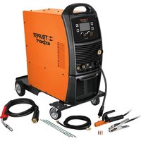
СОМУ-250X - Welding machine Truper - Free user manual and instructions
Find the device manual for free СОМУ-250X Truper in PDF.


| Product Type | Inverter Welding Machine |
| Brand | Truper |
| Model | СОМУ-250X |
| Input Voltage | 220V AC ±15% |
| Frequency | 50/60 Hz |
| Rated Input Current | 20A |
| Output Current Range | 30 - 250 A |
| Duty Cycle | 60% @ 250A |
| Welding Processes | MIG, TIG, Stick |
| Wire Diameter (MIG) | 0.6 - 1.0 mm |
| Electrode Diameter (Stick) | 2.0 - 4.0 mm |
| Weight | 15 kg |
| Dimensions (H x W x D) | 500 x 250 x 400 mm |
| Cooling System | Fan cooled |
| Protection Class | IP21 |
| Insulation Class | H |
| Power Factor | 0.93 |
| Efficiency | 85% |
| Operating Temperature | -10°C to 40°C |
| Storage Temperature | -20°C to 60°C |
| Safety Features | Thermal overload protection, Overcurrent protection |
| Included Accessories | MIG torch, ground cable, welding mask, brush |
| Maintenance | Clean dust regularly, check connections |
| Repairability | Replaceable modules |
Frequently Asked Questions - СОМУ-250X Truper
User questions about СОМУ-250X Truper
0 question about this device. Answer the ones you know or ask your own.
Ask a new question about this device
Download the instructions for your Welding machine in PDF format for free! Find your manual СОМУ-250X - Truper and take your electronic device back in hand. On this page are published all the documents necessary for the use of your device. СОМУ-250X by Truper.
USER MANUAL СОМУ-250X Truper
natural_image
Illustration of two types of automotive electrical connectors: a black cable with plug and a green clamp, and a black clamp with metal clasp (no text or symbols)SOMU-250X
natural_image
Illustration of a black cable with multiple connectors and a connector terminal (no text or symbols)natural_image
Three electrical component symbols on a gray background: a light bulb, a switch, and a hexagonal nut (no text or labels)MIG SMAW
TIG


natural_image
Close-up of a mechanical or electronic component with mounting holes and a small inset showing a small rectangular feature, labeled 'R' and 'B' (no readable text or symbols beyond labels)SMAW
Multi process welder
MIG
SMAW
TIG
Applies for:
Model Code
SOMU-250X 17259
250 A

natural_image
Illustration of two types of automotive electrical connectors: a black wire with plug and a gray clamp, next to a tire (no text or symbols)SOMU-250X

TRUPER® expert
Technical Data 3
Power Requirements 3
General Power Tool Safety Warnings....4
Safety Warnings for Welders 5
Parts 7
Interface 8
Installation 9
Start Up 13
Maintenance....17
Troubleshooting 18
Symbology 19
Authorized Service Centers 20
Branches 22
Warranty Policy 22
Contents
CAUTION
To gain the best performance of the tool, prolong the duty life, make the Warranty valid if necessary, and to avoid hazards of fatal injuries please read and understand this Manual before using the tool.
Keep this manual for future references.
The illustrations in this manual are for reference only. They might be different from the real tool.

Technical Data
TRUPER®
expert
| Code | 17259 | Description | Multi Process Welder |
| Input | |||
| Voltage | 220 V ~ | Frequency | 60 Hz |
| Current | 53 A | Input Rated Capacity | 11,6 kVA |
| Output | |||
| Welder Process | MIG, TIG y SMAW | ||
| Open circuit Voltage | MIG : 77 V c.c. | TIG: 13 V c.c. | SMAW : 77 V c.c. | ||
| Current Range | MIG : 18 A - 250 A | TIG: 13 A - 250 A | SMAW : 20 A - 220 A | ||
| Duty Cycle | 60% - 6 minutes' work per 4 minutes' rest.The output values are given in a 68 °F temperature.In higher temperatures, the duty cycle may be reduced. | ||
| Micro Wire Diameter | 0,023" | 0,031" | 0,035" | 0,039" | 0,043" | ||
| Micro Wire speed | 7.2 ft / min - 44.6 ft / min | ||
| Electrode diameter | SMAW: Type: 6013 3/32" | 1/8" | 5/32" | 3/16"Type: 7018 3/32" | 1/8" | 5/32" | ||
| 1 mm | 1,6 mm | 2 mm | 2,4 mmTIG: | |||
| Cooling Type | Fan Forced | ||
| Insulation | Class I | IP Grade | IP21S |
| Conductors | 12 AWG x 3C cwith 221 °F insulation temperature | ||
| Power cord grips used in this product: Type "Y".Build quality: Basic insulationThermal insulation on motor winding: Class H | |||
WARNING Avoid the risk of electric shock or severe injury. When the power cable gets damaged
it should only be replaced by the manufacturer or at a TRUPER® Authorized Service Center.
The build quality of the electric insulation is altered if spills or liquid gets into the tool while in use.
Do not expose to rain, liquids and/or dampness.
WARNING Before gaining access to the terminals all power sources should be disconnected.

Power Requirements
WARNING
- The tool shall be connected to ground while in use to prevent an electric shock.

The welder shall be installed as close as possible to the main power supply. Double check the power supply has the same voltage than the one indicated in the motor nameplate.
WARNING ce shall be grounded.
CAUTION er cables are codified with the following colors:
GREEN GROUND
WHITE CURRENT
BLACK CURRENT
- If using the welder together with more tools sharing the same ground, connect the tools in parallel. Never connect in a series.

- The ground conductor cable gauge cannot have a lower gauge than the power supply cable.

- The connection to the power source shall be carried out by a professional electrician.
power supply voltage.
- Confirm always that the input connection voltage stipulated in the welder nameplate matches the

- The power supply cable gauge shall comply with the following requirements:
| Switch | ≥ 30 A |
| Fuse (Rated working Current) | 40 A (*) |
| Electric Wire | ≥ 2,5 mm ^2 |
* The fuse fusion current is double of the rated current.
- In the event of needing extension cables between the welder and the work piece, increase the welding cable gauge to keep the welder energy output with a potential drop not higher than 4 V

WARNING! Read carefully all safety warnings and instructions listed below. Failure to comply with any of these warnings may result in electric shock, fire and / or severe damage. Save all warnings and instructions for future references.
Work area
Keep your work area clean, and well lit.
Cluttered and dark areas may cause accidents.

Never use the tool in explosive atmospheres, such as in the presence of flammable liquids, gases or dust.
Sparks generated by power tools may ignite the flammable material.

Keep children and bystanders at a safe distance while operating the tool.
Distractions may cause loosing control.

Electrical Safety
The tool plug must match the power outlet. Never modify the plug in any way. Do not use any adapter plugs with grounded power tools.
Modified plugs and different power outlets increase the risk of electric shock.

Avoid body contact with grounded surfaces, such as pipes, radiators, electric ranges and refrigerators.
The risk of electric shock increases if your body is grounded.
Do not expose the tool to rain or wet conditions.
Water entering into the tool increases the risk of electric shock.
Do not force the cord. Never use the cord to carry, lift or unplug the tool. Keep the cord away from heat, oil, sharp edges or moving parts.
Damaged or entangled cords increase the risk of electric shock.
When operating a tool outdoors, use an extension cord suitable for outdoor use.
Using an adequate outdoor extension cord reduces the risk of electric shock.
If operating the tool in a damp location cannot be avoided, use a ground fault circuit interrupter (GFCI) protected supply.
Using a GFCI reduces the risk of electric shock.
Personal safety
Stay alert, watch what you are doing and use common sense when operating a tool. Do not use a power tool while you are tired or under the influence of drugs, alcohol or medication.
A moment of distraction while operating the tool may result in personal injury.
Use personal protective equipment. Always wear eye protection.
Protective equipment such as safety glasses, anti-dust mask, non-skid shoes, hard hats and hearing protection used in the right conditions significantly reduce personal injury.


Prevent unintentional starting up. Ensure the switch is in the "OFF" position before connecting into the power source and / or battery as well as when carrying the tool.
Transporting power tools with the finger on the switch or connecting power tools with the switch in the "ON" position may cause accidents.
Remove any wrench or vice before turning the power tool on.
Wrenches or vices left attached to rotating parts of the tool may result in personal injury.
Do not overreach. Keep proper footing and balance at all times.
This enables a better control on the tool during unexpected situations.
Dress properly. Do not wear loose clothing or jewelry. Keep hair, clothes and gloves away from the moving parts.
Loose clothes or long hair may get caught in moving parts.

If you have dust extraction and recollection devices connected onto the tool, inspect their connections and use them correctly.
Using these devices reduce dust-related risks.
Power Tools Use and Care
Do not force the tool. Use the adequate tool for your application.

The correct tool delivers a better and safer job at the rate for which it was designed.
Do not use the tool if the switch is not working properly.
Any power tool that cannot be turned ON or OFF is dangerous and should be repaired before operating.
Disconnect the tool from the power source and / or battery before making any adjustments, changing accessories or storing.
These measures reduce the risk of accidentally starting the tool.
Store tools out of the reach of children. Do not allow persons that are not familiar with the tool or its instructions to operate the tool.

Power tools are dangerous in the hands of untrained users.
Service the tool. Check the mobile parts are not misaligned or stuck. There should not be broken parts or other conditions that may affect its operation. Repair any damage before using the tool.
Most accidents are caused due to poor maintenance to the tools.

Keep the cutting accessories sharp and clean.
Cutting accessories in good working conditions are less likely to bind and are easier to control.
Use the tool, components and accessories in accordance with these instructions and the projected way to use it for the type of tool when in adequate working conditions.
Using the tool for applications different from those it was designed for, could result in a hazardous situation.
Service
Repair the tool in a TRUPER Authorized Service Center using only identical spare parts.
This will ensure that the safety of the power tool is maintained.
Children or people with reduced physical, sensory or mental capabilities shall not operate the tool, neither inexperienced people or without knowledge in the use of the tool, unless supervised by a person responsible of their safety or if receiving previous instructions about the tool operation.
Children shall be kept under supervision to double-check they will not play with the tool. Tight supervision shall be used with children or disabled persons to prevent from using or being close to any household tool.

Safety Warnings for Welders
Welder protection equipment
WARNING • Wear Welding mask to protect eyes and face when working with the welder. Double check the mask shade lens is adequate for the welding process to carry out.
CAUTION • Wear special welding hide gloves as well as bib and leather chaps.

- Wear clothes with robust materials and long sleeves made of fire resistant materials such a wool or leather.
- Use screen or special curtains to insulate the work place from passerby and protect them from sparks, flare and slag originated by the welding process.
- Benches and work tables where the work piece rests shall have orifices or slots to let the residues originated in the welding process pass through.
To prevent electric shock
CAUTION • Verify there is a safe connection for the input and output cables, that the cables are correctly insulated and the connections are in good repair (check and eliminate any possibility of electric shock).

CAUTION • Double check the welder ground connection is reliable.
CAUTION • The welding power sources are not adequate to be used under rain or snow.
CAUTION • Keep yourself insulated from the work piece and ground, stepping in insulated and dry mats.
DANGER • For no reason at all touch both poles of the welder circuit (welding rod and work piece).
WARNING • Do not try to adjust the welder voltage when carrying out welding jobs.
CAUTION • Connect the ground clamp to the work piece as close as possible from the welding zone to prevent the current to flow through long distances and thus, eliminate the possibility of an electric shock.
WARNING • Disconnect the welder from the power supply before carrying out maintenance.
To prevent risks to your health
WARNING • Vapor and gasses produced during the welding job are dangerous to your health. Work in ventilated places or with an adequate ventilation system.

WARNING • Do not breath in smoke and gasses produced during the welding process. Keep your head away from the fumes.
DANGER • When the ventilation is poor, wear an adequate autonomous breathing system. Protection gases generated by the welding may displace air and cause a fatal accident.
CAUTION • Do not operate the welder in the vicinity of degreasing products, cleaners or aerosol cans. The heat and radiation coming from the welding process may react with the vapors and produce toxic gas.
CAUTION • Avoid welding in lead, zinc or cadmium covered metal. Those materials generate toxic gases. Otherwise, remove the covering from the welding area. Make sure the work area is well ventilated or use an adequate autonomous breathing device.
To prevent fire
CAUTION • Have always handy an extinguisher in good working condition.

WARNING • There shall never be flammable or explosive materials in the work area, (not less than 36 ft). Do not carry out welding jobs in places where sparks could reach or fall onto flammable or explosive materials.
WARNING • Sparks, hot metal, welding slag, workpiece and hot parts of the equipments can cause fire.


To prevent injuries and accidents
WARNING • Risk of electric shock! An electric shock originated in the welder electrode can cause death.

Do not weld under rain or snow. Do not touch the electrode with bare hands. Do not wear wet or damaged gloves. Protection for people against electric shock: insulate yourself from the work piece. Do not open the equipment enclosure.
WARNING • Risk Generated by The Arc!

The arc radiation may burn eyes and damage skin. Wear protection mask and glasses. Wearing hearing protection and protective clothes that protect skin up to the neck. Wear complete protection for the body.
WARNING • Risk induced by magnetic fields! The welding current produce electromagnetic fields.

Do not use the power source if having a medical implant. Never roll welding cables around the body. Set together and parallel the two welding cables so that the fields in each one will counteract.
WARNING • Do not use the welder power source to de-ice pipes.
CAUTION • Never allow people with no experience, to dismount or regulate the welding machine.
WARNING • Make sure that both, the operator and the welding machine are away from the sparks and residues originated by the welding process.
- The welder shall be operated in a place protected from sun and rain. Away from places where there are violent vibrations.
- The welder shall be stored in a place with no humidity and with a temperature range of -13^ to 131^
WARNING • Room temperature range when performing welding jobs: 14 °F to 104 °F
- There shall be 20" space around the welding machine to provide good ventilation.
CAUTION • The welder power source base shall have an inclination of 10^ maximum to prevent rollover.
CAUTION • Make sure no foreign metal object gets inside the welder.
WARNING • Any problem with the welding machine that cannot be solved by the operator after making the correct adjustments to get a good welding process shall be solved in a
TRUPER Authorized Service Center. For no reason at all try to open the welder cover to carry out any type of maintenance.
Gas handling
- Gases used in the welding process are inert gases that do not react under normal conditions. These gases are colorless, odorless and flavorless.
- Do not burn nor withstand combustion.
CAUTION • These gases displace air this cause asphyxiation in confined atmospheres or poorly ventilated.
WARNING • Do not use the welder in confined spaces or with bad ventilation. Failing which, dizziness, fainting or even death can be induced due to lack of oxygen.
Gas Connections
CAUTION • Double check every connection, hoses and washers are in good repair. Replace immediately those showing any type of damage.
TRUPER® expert
CAUTION • Make sure all the threads and connections are clean and free of oil and grease. Oils and grease when in contact with pressurized gas may be explosive.
- When making connections, double check tightness.
CAUTION • Use soapy water to detect any leak and correct it before turning on the welder.

Use of compressed gas cylinders
WARNING • Compressed air cylinders are widely used in many welding processes. If not stored, handled, inspected and used adequately, compressed gas cylinders can be deadly. May explode or turn into missiles with great power that can break even brick walls.
CAUTION • Inspect the cylinders. Look for external corrosion, slits, bulging, holes or wells. If in doubt if any imperfection observed is acceptable under these guidelines, then, stop using the cylinder. Consult the gas safety sheet before using.
CAUTION • Many compressed gasses not only represent a physical danger but also are hazardous to your health. Make sure you know the health hazards and how to protect yourself. Always follow the use cautions warnings and handling measures provided in the safety sheet.
Safety Warnings for Welders
CAUTION • Never place the cylinders in the vicinity of heat or near open flames or any resource that could turn into a part of an electric circuit. Do not use the cylinder to connect to ground during the electric welding process.
WARNING • Wear safety lenses and protective mask when connecting and disconnecting the regulators and lines of the cylinder.
CAUTION • Close the cylinder valve to release pressure before removing the regulator and when the cylinder is not in use. The cylinder shall be stored with a visible identification and with the protection valve cap set in place.
CAUTION • Purge the passing of gas before using a new cylinder. Stand aside the cylinder valve. Never stand in front of it. Before setting the gas regulator into the cylinder, open and close the valve quickly to expel any foreign particle which could be housed into the valve.
- Adjust pressure adequately not to waste gas. If the regulators indicate external pressure, correct immediately.
CAUTION • Purge all the system after each use. DO NOT disconnect the equipment when the cylinder valves are open.
- In the event of a gas leak, move the cylinder to an open area and immediately report it to the supervisor or Civil Protection.
MIG Weld
MIG Welders
• These welders work with an electric arc produced between the continuous electrode (micro wire) and the work pieces. The arc is protected from the surrounding atmosphere by the inert gas. It is expelled at the same time than the electrode while welding.
FCAW Welders
• These welders also work with an electric arc produced between the continuous electrode (micro wire) and the work pieces. Do not require gas because the arc is protected from the surrounding atmosphere by the gas produced in the combustion in the electrode core while welding.
The micro wire weld shows the following characteristics:
- The arc is easily generated. It is stable during the welding process and produces a good weld seam.
• The seam stays protected against oxidation and cracking due to its low hydrogen content. - The narrow electrode lessens the possibility or work piece malformation.
• Energy and materials saving with high efficiency in production, lessening operation costs.
• Highly concentrated heat in the arc with strong cast center penetration. Few soldering layers and high electrode casting index. - Can carry out high-speed soldering with no slag. When there is no need of removing slag, jobs with multiple soldering layers are carried out in less time.
• Welding can be carried out in any position. - Adequate to weld mild steel or alloy steel.
• Perfect overheating protection function.
• Is adequate for automotive manufacturing, ships construction, mechanic industry, etc.
TIG Welding
It is a welding procedure with no fusing electrode under gaseous atmosphere. This technique can be used with or without weld metal. The inert gas, generally Argon, insulated the fused metal of the exterior atmosphere preventing its contamination. The electric arc is established between the non-consumable tungsten electrode and the work piece. The inert gas also covers the electrode preventing any oxidation possibility.
SMAW Welding
The arc welding process is one of the most used and encompasses diverse techniques. One of these techniques or the arc welding with metallic covered electrode (SMAW English Acronym). Also, known as arc welding with covered electrode, rod welding or manual welding with metallic arc. This is a technique where the welding heat is generated by an electric arc between the work piece (metal base) and a consumable metallic electrode (weld metal) covered with chemical materials in an adequate composition (flux).

Control Panel
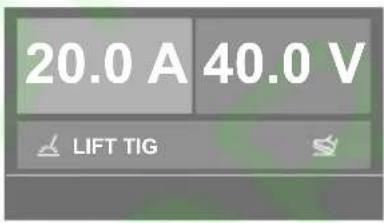
- LCD Screen: Shows all the processes, from the function selection to welding parameters.
- Gas Check Button: Press the button to star the gas supply system.
- Wire Check Button: Press the button to start the wire supply system.
- Home Button: Keep the button pressed. To return to the Home Page.
- Return Button: Press to go back to the previous step.
- Multiple Adjust Knob: Turn to select functions and press to confirm. Adjust in a precise manner the current and wire feeding speed.
- Auxiliary Knob: To adjust tension in a precise manner.
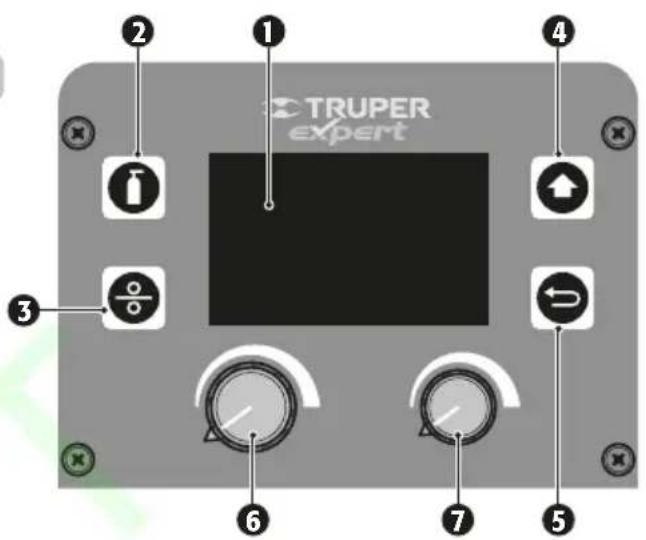
Interface Description
- The interface displayed in the LCD screen is controlled with the buttons and adjusting knobs. The adjusting knobs, are turned to select and are pressed to confirm.

Multiple Function Selection: 8 welding functions + one configuration.

natural_image
Three simple electrical circuit symbols on a gray background: a bulb, a valve, and a hexagonal bolt (no text or labels)Output Configuration: Shows the output connection under different welding modes.

Electrode Selection / Wire Diameter: Shows electrode options / wire diameters.
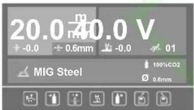
MIG SMAW
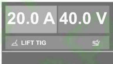
TIG

Shows all the parameters selected for the welding function selected. More precise configurations can be set with the multiple functions knob. Press to confirm.

Material Thickness: Select different thicknesses with the multiple functions knob. Press to confirm.

Interface Configuration: Shows Language Configuration, Unit Configuration, Light Configuration and Information and Recovery.

Alarm: Shows when the machine activates the thermal protection because the temperature of its interior is too high. The welder output is automatically disconnected but the fan continues to operate. When the internal temperature drops, the warn! interface shuts down and the machine is ready to operate again.
Gas Cylinder (MIG)
CAUTION • The cylinder platform, chains or any other type of support shall not damage or put in risk the valve or gas cylinder. Cylinders can explode if damaged.
- The cylinder platform (A) accommodates small or medium cylinders up to 1 m tall.
- Set the gas cylinder onto the platform and secure with the chain (B).
CAUTION • Be aware of all the indications and safety warnings in this Manual when carrying out connections.
- Purge the cylinder as indicated in page 6, in the "Use of Compressed Gas Cylinder" item.
- CO^2 cylinders have valves that can be screwed directly to the regulators. The Argon gas o Argon mix cylinders need an adapter with round tip (C) to connect a regulator.
- Tighten the regulator connection to the cylinder valve using a wrench.

Gas Connection (MIG)
- Connect the end of the hose into the regulator (D) outlet and the other end into the welder (E) gas inlet. Tighten both connections to make sure the system is well sealed.
- Before opening the cylinder valve, close the regulator valve turning in a counterclockwise direction. When opening the cylinder valve, double check the regulator is not pointing towards you.
- Set the regulator flow rate to 5 L/min - 8 L/min. The flow rate depends on the material to be welded and the presence of wind gusts that could alter the gas flow.
- To weld steel low in carbon and most of the jobs, CO^2 is used, even though the process expels a lot of projectiles.
- CO^2 mixed with argon reduce the projectiles during the job.
• To weld aluminum, use Argon gas.
CAUTION • The welding machine with microwire can be used with or without gas depending on the requirements of the job or the type of wire used:
- Solid wire (GMAW). Gas is required to protect the electric arc.
- Wire with Flux core (FCAW). Gas is not required as the combustion of the wire core generates the necessary gases to protect the electric arc.
Torch Connection (MIG)
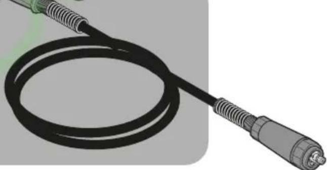
- Align the torch connector pins (F) into the energy, gas and micro wire energy outlets (G) in the welder front panel. It is important that all the pins are aligned, because of the connection with the power supply, the micro wire feeding system and the gas supply to the torch. - Once aligned, press the connector into the contact and turn the blocking ring (H) in a clockwise direction to tighten the connection.

Micro Wire Spool (MIG)
CAUTION • Turn OFF and disconnect the welder before opening the cabinet door.
- Push the cabinet lock upwards to open and gain access to the micro wire feeding system.
- Loosen the retainer knob (J) turning in a clockwise direction and remove from the axis (K).
• Install the micro wire spool (L) into the axis.
- Set back the retainer and tighten enough so that the micro wire rotates feely.
- Using plyers, release the micro wire end from the spool notch. Make sure the micro wire sticks out from the spool lower side toward the micro wire feeding mechanism direction (M).
- Check that the micro wire tip is not crooked, bent or showing alteration or burrs. Cut if necessary so that the tip is straight and flawless.

- The micro wire diameter depends on the thickness of the material to be welded. Small diameter micro wire allows working with low energy range, deliver less material into the weld and are easy to control, while the larger micro wire diameters require more energy to melt the electrode, deliver more material to the weld and are difficult to control. - The welder can use wires made of different materials and characteristics, such as solid wires for gas welding, wires with core for welding without gas, or aluminum wires for aluminum welding. Read the specifications of the spool manufacturer to verify the micro wire is adequate for the job before installing into the welder.
CAUTION • Verify the torch contact nozzle diameter matches the diameter of the micro wire installed in the welder. Otherwise, the passing of the micro wire can get blocked.
Micro Wire Feed (MIG)
CAUTION • Turn OFF and disconnect the welder before starting the micro wire feeding operation.
- Open the micro wire feeding mechanism moving the block / tension knob (A) downwards and front. The pressure rod (B) will open uncovering the feeding rod (C).
- Release the micro wire from the spool and cut any bent, damaged or burr portion at the end of the micro wire. Keep the micro wire tension at all times to prevent unrolling the spool.
- Straighten approximately 1.7" of micro wire and push lightly through the feeding mechanism.
- Double check the micro wire is aligned with the notch that suits the feeding rod diameter (D) This is important to allow the micro wire to be pushed right. The feeding rod has two notches. For 0.023" and 0.031" wires. This welder includes an additional feeding rod for 0.031" and 0.039" wires. To select which notch to use turn the retainers (E) and remove them. The selected notch size is shown in the feeding rod side (F). If you need using the other notch, remove carefully the feeding rod and turn it around (G). Remember that the notch to select is always the one farthest away from the knob.
- Turn the pressure rod back into the original position and secure lifting the blocking / tension knob. Turn the tension knob into a medium position, for example, between 2 and 3.
- Hold the torch to remove the nozzle tip (H) and unscrew carefully.
- Then, unscrew the contact nozzle (I) to remove it and release the torch outlet.
- Check the welder switch is in the OFF position and the grounding clamp is away from the torch tip.
- Connect the welder to the power supply and turn ON the welder switch.
- Unroll completely the torch cable to make it as straight as possible and press the micro wire feeding button (J) in the control panel. The micro wire (K) will start being fed through the cable and the torch. Have the micro wire sticking out 4" approximately through the torch outlet.
- Turn OFF the welder and disconnect from the power supply.
- Slide the contact nozzle over the micro wire and screw it in place again.
- Slide the nozzle tip through the micro wire and screw carefully in the torch outlet.


Micro Wire Feeding Rhythm
- Connect the welder to the power supply and turn ON the welder switch to verify the micro wire feeding rhythm.
- The micro wire speed to the torch is controlled from the control panel with the MIG welding function selected (see page 14).
- Regardless of the speed selected, the micro wire shall be fed continuously and shall be stopped immediately when releasing the torch trigger. If the micro wire shows trouble going out or is not stopping after releasing the trigger, you need to make two adjustments:
- Adjust pressure on the micro wire with the tension knob (L). Be mindful that excessive pressure hinders feeding micro wire, while an insufficient pressure cannot push the micro wire.
-
Tighten the spool knob (M). If the knob is loose, the spool could go on turning after releasing the torch trigger and the micro wire feed would not stop immediately.
-
Remember that the torch cable shall be totally unrolled so that the micro wire can circulate correctly.
- Cut the remaining micro wire to stick out 8mm to 10 mm from the contact nozzle, depending on the job to carry out.
- Close the cabinet. The welder is ready to work.

Preparations
- Only with experience, practice and care a good welding job can be guaranteed.
- The factors inventing in the welding process are many: required current, distance between the electrode and the work piece, welding speed and direction, thickness and type of material, position of the work piece, electrode angle and in addition, electrode caliber, material and electrode covering. Therefore, is advisable that before carrying out any welding job, make trial practices in scrap material to determine which are the specific requirements of the work.
- The work pieces' area where the welding is going to be applied shall be free of oxide and paint.
- The joints between sheets with calibers higher than 1/8" must be beveled to get an adequate weld (A).
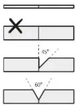

Turn ON
- Turn ON the general switch (B) in the back of the welder.
- When tuning ON the switch, the LCD screen will be ON and the internal fan will start working.
Adjustments
- As a general rule, low currents require that the micro wire be fed using low speed. If is necessary to increase the work current, the micro wire speed shall increase likewise.
- Remember to make tests in scrap material with the same characteristics of the material to be work with because, aside from the micro wire current and speed there are other factors involved in the welder performance such as diameter and characteristics of the micro wire, distance between the nozzle and the work material, the angle of the torch and the amount of gas supplied.

natural_image
Close-up of a mechanical component with mounting holes and a small inset showing a labeled section (no text or symbols)Connection Configurations
CAUTION • All the connections in the control panel shall be perfectly tight in their power supplies. To secure the connections turn clockwise.
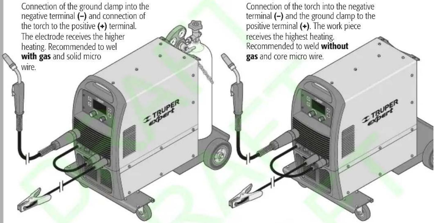
- The electrode polarity can be modified depending on welding work requirements or needs. Remember to make trial test in scrap material to define the right configuration before working on the work piece.
MIG Weld
Interface Home Minimum and maximum parameters of the manual MIG process


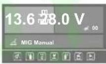
NOTE: For the "MIG ALUMINUM, MIG STAINLESS STEEL, MIG CARBON STEEL, MIG COPPER SILICON functions, values are pre-established by the machine software. The adjustment depends on the type of material to work with.
Weld with SMAW electrode
Connection of the electrode into the negative terminal (−) and the ground clamp into the positive terminal (+). The work piece receives higher heat, thus produces less distortion of the piece and narrower weld seams, makes it ideal to weld thin pieces.
Connection of the clamp to ground into the negative terminal (−) and the electrode into the positive terminal (+). The electrode receives higher heat producing more penetration with basic electrode. Makes it ideal to weld thick pieces.

Interface Home Minimum and maximum parameters of the manual arc process


Connection of the ground clamp into the positive terminal (+) and the torch connection into the negative terminal (−). Connect the torch gas inlet (A) to the output valve in the protection gas regulator.

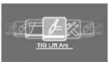
Interface Home Minimum and maximum parameters of the manual TIG process


Operation
- In order to assure the flow of the electric circuit you must clean the work pieces 0,78" to 1,18" around the zone where the ground clamp will be connected and around the zone to be welded.
- Connect the ground clamp to the work piece or the work bench where the work piece is supported.
- Connect the welder to the power supply.
- Once the welder is duly installed, connected and configured, and all the safety measures are taken care of, you can start working the welder.
- Use the welding mask.

MIG
- Select the MIG function (micro wire ) in the LCD screen.
- Hold the torch with your hand and point the contact nozzle towards the slot to weld. Use a 30^ angle approximately. It should allow you to see the contact point between the electrode and the work piece.
- Lower the welding mask.
- Make contact with the micro wire tip onto the work piece while pressing the torch trigger (A). The current will generate the electric arc (B) between the work piece and the micro wire (C).
- With the GMAW weld, while the micro wire is fed, gas (D) is expelled to protect the arc.
- To stop the job, release the torch trigger. Current will stop passing, the micro wire will stop as well as the gas flow.
TIG
- Select the TIG function (tungsten electrode ≈) in the LCD screen.
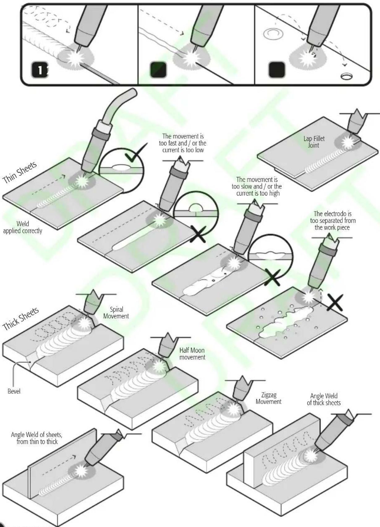
• To start the arc, place the nozzle in an angle onto the work piece (1). - Lift the torch but do not separate the nozzle from the work piece to put the electrode near the work piece (2).
- When the arc is started lift the torch so that the electrode tip stays at 0,078" from the work piece (3) and start welding.
- We recommend keeping the electrode at 90^ in the vertical while welding to guarantee the protection from the gas.
CAUTION • For this process, an AN-GRUPO1 torch is required and a tank or can of protection gas not included.


SMAW
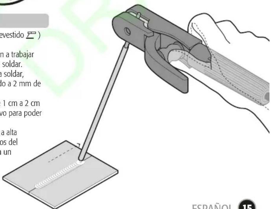
- Select the SMAW function (covered electrode ) in the LCD screen.
- Aim the electrode tip towards the joint to be worked to generate the electric arc and to start welding.
- Once the arc is lit start welding keeping always the electrode tip at a distance of 0,078" away from the work piece.
- When the electrode has consumed 0,39" to 0,78" from the electrode colder, replace it with a new one to keep on welding.
CAUTION • The electrode burns in a high temperature. Do not try to manipulate the remains of the electrode with your hand. Place the remains in a metal container.

Basic Types of MIG - TIG Weld Joints
- Weld joints between thick sheets with a space between the joint to be welded and requiring more delivery of material in the joint, we recommend to make a circular movement with the nozzle.
- Weld joints between thin sheets in the union to be welded, we recommend making and lineal and continuous movement with the nozzle to prevent the material coming out of shape.
- Weld joints between over imposed sheets with orifices previously drilled.
flowchart
graph TD
    A["Bevel"] --> B["Thick Sheets"]
    B --> C["Half Moon movement"]
    C --> D["Spiral Movement"]
    D --> E["Lap Fillet Joint"]
    E --> F["The electrode is too separated from the work piece"]
    F --> G["Zigzag Movement"]
    G --> H["Angle Weld of thick sheets"]
    H --> I["Angle Weld of sheets, from thin to thick"]
    I --> J["Thin Sheets"]
    J --> K["Weld applied correctly"]
    K --> L["The movement is too fast and / or the current is too low"]
    L --> M["The movement is too slow and / or the current is too high"]
Maintenance
- A correct use and good maintenance will lengthen the useful life of the welder.
CAUTION • Only Certified personnel shall carry out repairs. We recommend visiting a TRUPER® Authorized Service Center to repair the welder and purchase supplies and accessories.
- Before carrying out any type of repairs, please cut please the power supply.
- Check regularly that the input and output cables are firmly connected and are not exposed. Any anomaly shall be repaired immediately.
Storage
- In the event the welder is to be stored for long periods of time, it shall be kept in a dry and well ventilated place to prevent humidity, oxide or toxic gases enter the machine.
The storage temperature can be from -13 °F and up to 131 °F, and the relative humidity shall not be over 90%.
Nozzle
- The nozzle (D) shall be clean and free of spills. The accumulation of spills inside the nozzle can cause an electric shock in the contact tip and can blow a fuse in the printed circuit or can cause expensive repairs to the machine. To keep the contact tip free of spills and to learn how to remove and replace it.
- Apply anti-adherence ointment into the nozzle before starting to weld.
Torch Cable (MIG)
- Protect the mechanical wear in the torch cable mount (B).
- To clean the covering set back the micro wire rewinding the spool. Secure the micro wire to the spool and disconnect the mount from the torch in the control panel.
- Clean the inner covering with compressed air, administered from the mount and up to the torch. If the covering is clogged, replace the torch.
Micro Wire Feed Mechanism
- Verify regularly the micro wire feed mechanism. the cleansing of the notches from the feed rod (A) is indispensable to get a good job. Clean the rods once a week, especially the feed rod notch. Eliminate any dust accumulation.

natural_image
Mechanical assembly diagram showing a motor or gear mechanism with labeled component A (no text or symbols present)
Cleansing
CAUTION Every time the dust is cleaned cut the power supply.
- To remove the dust from the too, use dry compressed air (use a compressor or a bellow) to remove the dust from inside the machine.
- If there is grease adhered, clean with a piece of cloth.
- The machine shall be cleaned thoroughly once a year if in good maintenance conditions and each three month if it has too much dirt accumulated.
- Check regularly the input and output cables from the welder to guarantee a good connection and prevent exposure. This checkup shall be carried out once a month when fixed and each time you need to remove them.

Problem Cause Solution
| The power source is interrupted. | · The weld pearl is irregular. | · The energy is restarted automatically when the unit gets to an adequate temperature, approximately after 15 minutes. |
| There is no welding current. | · Blown rectifier.· Wrong connection of the clamp with the work piece.· The ground line is broken.· The torch line is broken. | · Go to a TRUPER® Authorized Service Center.· Clean and polish the contact surface and the area around the weld.· Replace the ground line.· Replace the torch. |
| The micro wire feed mechanism is no operating and the energy indicator light is ON. | · The micro wire feed mechanism is damaged. | · Go to a TRUPER® Authorized Service Center. |
| The micro wire is not feed despite the spool is rotating. | · The pressure rod is not adjusted correctly.· There is residue accumulated in the torch internal covering.· Nozzle and / or contact are dirty or defective.· The micro wire is out of shape. | · Adjust the rod pressure.· Clean the covering with compressed air (see page 17).· Clean or replace if necessary.· Adjust the pressure in the feed rod. |
| The micro wire is fed unevenly. | · Accumulation of residues in the internal covering of the torch.· Nozzle tip and / or contact nozzle dirty or defective.· The feeding rod notch is dirty.· The feeding rod notch is damaged.· The pressure rod is not well adjusted. | · Clean the covering with compressed air, see page 17.· Clean or replace if necessary.· Clean the feeding rod.· Replace the feeding rod.· Adjust the rod pressure. |
| The arc is unstable. | · The configuration of controls and connections in the control panel is incorrect.· Impurities in the weld area.· Worn or defective nozzle. | · Check and correct the configuration.· Clean and polish the work pieces.· Replace the nozzle. |
| Pores are generated in the weld. | · There is no gas flow.· The nozzle tip is clogged.· There are air gusts that dissipate the gas.· Impurities in the welding area.· The torch is too far away or the work angle is wrong.· Gas leak.· Defective electro valve. | · Open the gas cylinder, regulate the gas valve.· Clean or replace if necessary.· Set a screen in the work area or increase the gas flow.· Clean and polish the work pieces.· Correct the distance between the nozzle and the work piece (from 0.31" to 0.39").· Check all the gas connections. Tighten all the joints.· Go to a TRUPER® Authorized Service Center for cleaning or replacement. |
| The electrode gets stuck to the nozzle tip. | · Worn or defective nozzle tip.· The micro wire is malformed.· The micro wire speed is too slow. | · Replace the nozzle tip.· Adjust the tension in the rod.· Increase the micro wire speed. |
| The weld pearl is irregular. | · The torch is in an incorrect working position.· The micro wire is stuck to the welding point. | · Correct the angle and direction of the torch when welding.· Adjust the speed configuration of the micro wire and current. |
Problem Cause Solution
| The welding pearl is very narrow and bulky. | · The welding current is too low.· The welding current is too fast. | · Increase the micro wire current and speed .· Displace the torch slower and / or make circular or zigzag movements with the nozzle. |
| Thee welding pearl is too wide. | · The welding current is too high.· The welding speed is too slow.· The arc is too long. | · Diminish the micro wire current and speed.· Displace the torch faster and / or use less circular or zigzag movements with the nozzle.· Correct the distance between the nozzle and the work piece (from 0.31" to 0.39"). |
| The weld has low penetration. | · The welding speed is too slow.· The arc is too long. | · Increase the micro wire current and speed.· Correct the distance between the nozzle and the work piece (from 0.31" to 0.39"). |
| The weld has too much penetration. | · The welding current is too high.· The welding speed is too slow.· The arc is too long. | · Diminish the micro wire current and speed.· Displace the torch faster. No dot make circular or zigzag movements with the nozzle.· Correct the distance between the nozzle and the work piece (from 0.31" to 0.39"). |
If after all the recommended actions have been carried out the problems persist, contact a TRUPER Authorized Service Center.
Symbology
| == | DC symbol |
| Electric arc manual welding with coated electrode | |
| Inert metal – active gas welding, including the use of flux core | |
| Input circuit, single-phase alternating current and rated frequency symbol | |
| x | Work cycle symbol (service factor) |
| I_2 | Nominal welding current symbol |
| U_2 | Conventional load voltage symbol |
| U_0... V | Rated open circuit voltage |
| U_1... V | Rated power voltage |
| I_1max... A | Maximum rated power |
| I_1eff... A | Maximum effective power |
| IP | Protection degree (solid objects and water submersion) |
| Converter - transformer - single-phase static frequency rectifier | |
| ~ | AC symbol |
| SMAW | Electric-arc manual welding with coated electrodes |
| TIG | Gas shielded arc welding system |
| MIG | Metal inert gas welding |
| Tungsten inert gas welding |
In the event of any problem contacting a Service Center, please see our webpage www.truper.com to get an updated list, or call our toll-free numbers 01(800) 690-6990 or 01 (800) 018-7873
to get information about the nearest TRUPER Authorized Service Center.
AGUASCALIENTES
671615 SUPER TOOLS
ZARAGOZA NO. 1205, COL. EL SOL, AGUASCALIENTES, AGS. TEL.: 01(449) 996-5978
BAJA
670796 CONTRURENTAS
CALIFORNIA SUR
CALLE D No. 31-A, COL. MODELO DE
ECHEGARAY, NAUCALPAN, EDO. DE MÉXICO,
C.P. 53330 TEL.: 01(55) 5371-3500
SUCURSAL CHIHUAHUA
AV. SILVESTRE TERRAZAS No. 128-11 PARQUE
INDUSTRIAL BAFAR, CARRETERA MÉXICO
CUAUHTEMOC, CHIHUAHUA, CHIH.
TEL.: 01 (614) 43 40 052
SUCURSAL CULIACAN
LIBRAMIENTO BENITO JUÁREZ No. 5599 B4,
EJIDO DE LAS FLORES (LA COSTERITA),
CULIACAN, SINALOA, C.P. 80296
CONMUTADOR: 01(667) 760-5747
SUCURSAL GUADALAJARA
ADOLF BERNARD HORN No. 6800,
TLAJOMULCO DE ZUÑIGA, JALISCO, C.P. 45655
CONMUTADOR: 01(33) 3606-5290
SUCURSAL LAGUNA
CALLE METAL MECÁNICA No. 280, PARQUE
INDUSTRIAL ORIENTE, TORREÓN, COAHUILA,
C.P. 27278 CONMUTADOR: 01(871) 209-6823
SUCURSAL MÉRIDA
This product, its parts and components have a one year cover against any defects in material and/or workmanship as well as its function, without expense for the customer. This warranty excludes the following: 1) when product is used under different from normal conditions; 2) usage in breach of the operating manual furnished or; 3) when this product has been altered or repaired by personnel not certified by TRUPER.
This warranty shall be effective with the supplier selling the product, or at TRUPER Authorized Service Centers listed in this manual.
This warranty shall be effective when presenting the product and the valid Warranty policy duly stamped by the supplier or the proof of purchase.
To comply with this warranty, Truper will cover transportation expenses in case consumer's address is out of range from TRUPER® Authorized Service Centers listed herein or at the website www.truper.com or at our toll free numbers: 01 (800) 690-6990 or 01(800) 018-7873.
In the event of any problem regarding the validity of this warranty please call toll free numbers mentioned above.
Parts, components, consumables and accessories when applicable may be acquired at TRUPER Authorized Service Centers listed herein.
Stamp of the business:

1 YEAR
Date of purchase:
Imported by: TRUPER, S.A. de C.V.
Parque Industrial No.1, Jilotepec, C.P. 54240, Estado de México, México
TEL. 01(761) 782 91 00, (TIN) R.F.C.: THE-791105-HP2
www.truper.com
- SMAW
- Multi process welder
- MIG
- TIG
- TRUPER® expert
- Contents
- CAUTION
- Power Requirements
- WARNING
- Work area
- Electrical Safety
- Personal safety
- Power Tools Use and Care
- Service
- Safety Warnings for Welders
- Welder protection equipment
- To prevent electric shock
- To prevent risks to your health
- To prevent fire
- To prevent injuries and accidents
- Gas handling
- Gas Connections
- Use of compressed gas cylinders
- MIG Weld
- MIG Welders
- FCAW Welders
- TIG Welding
- SMAW Welding
- Control Panel
- Interface Description
- Gas Cylinder (MIG)
- Gas Connection (MIG)
- Torch Connection (MIG)
- Micro Wire Spool (MIG)
- Micro Wire Feed (MIG)
- Micro Wire Feeding Rhythm
- Preparations
- Turn ON
- Adjustments
- Connection Configurations
- Weld with SMAW electrode
- Operation
- Basic Types of MIG - TIG Weld Joints
- Maintenance
- Storage
- Nozzle
- Torch Cable (MIG)
- Micro Wire Feed Mechanism
- Cleansing
- AGUASCALIENTES
- BAJA
- CALIFORNIA SUR
- SUCURSAL CHIHUAHUA
- SUCURSAL CULIACAN
- SUCURSAL GUADALAJARA
- SUCURSAL LAGUNA
- SUCURSAL MÉRIDA
Brand : Truper
Model : СОМУ-250X
Category : Welding machine