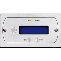
DRM-882WPX - Remote control Monacor - Free user manual and instructions
Find the device manual for free DRM-882WPX Monacor in PDF.


| Product Type | Remote Control |
| Brand | Monacor |
| Model | DRM-882WPX |
| Dimensions (approx.) | 20 x 5 x 2 cm |
| Weight (approx.) | 100 g |
| Power Supply | 2 x AAA batteries (not included) |
| Transmission Type | Infrared (IR) |
| Range | Up to 8 meters |
| Number of Buttons | 29 |
| Main Functions | Power, Volume, Channel, Menu, Navigation, Numeric Keypad, Mute, Input Select |
| Compatible Devices | Monacor audio/video equipment (e.g., amplifiers, receivers, CD players) |
| Programming | Not programmable; dedicated for Monacor devices |
| Battery Life | Approximately 1 year with normal use |
| Material | ABS plastic |
| Color | Black |
| Cleaning Instructions | Wipe with a soft, dry cloth. Do not use liquids or abrasive cleaners. |
| Safety Warnings | Keep away from moisture and heat sources. Do not disassemble. Remove batteries if not used for extended periods. |
| Battery Replacement | Open battery compartment cover on back, replace with fresh AAA batteries (2 pcs), observe polarity. |
| Repairability | Battery contacts cleanable; no user-serviceable internal parts. For repair, contact Monacor service. |
| Environmental Conditions | Operating temperature: 0°C to 40°C; Humidity: <90% non-condensing |
| Certifications | CE, RoHS |
Frequently Asked Questions - DRM-882WPX Monacor
User questions about DRM-882WPX Monacor
0 question about this device. Answer the ones you know or ask your own.
Ask a new question about this device
Download the instructions for your Remote control in PDF format for free! Find your manual DRM-882WPX - Monacor and take your electronic device back in hand. On this page are published all the documents necessary for the use of your device. DRM-882WPX by Monacor.
USER MANUAL DRM-882WPX Monacor
DRM-882 LAN Bestellnummer • Order Number 17.9250
DRM-882WP Bestellnummer • Order Number 17.0014
DRM-882WPX Bestellnummer • Order Number 17.0015
CE
BEDIENUNGSANLEITUNG
INSTRUCTION MANUAL

English ...... Page 22
--- TCP/IP Setup ---
Dhcp = Off
SP02 S1 = 0 S2 = 1 S3 = 0 S4 = 0
Abb. 16 Fenster „IP Search“
System Lock PC Connection
oder
System Lock Online Device ID [01]
Abb. 22 Noise-Gate
6.4.7 Klangeinstellung
Abb. 38 Fenster „Configure External Signal“
| Priority | With mode = Signal Active High | With mode = Signal Active Low |
| 0 | recall program E4 if S4 = 1 or recall program E3 if S3 = 1 or recall program E2 if S2 = 1 or recall program E1 if S1 = 1 | recall program E4 if S4 = 0 or recall program E3 if S3 = 0 or recall program E2 if S2 = 0 or recall program E1 if S1 = 0 |
| 1 | recall program E3 if S3 = 1 or recall program E2 if S2 = 1 or recall program E1 if S1 = 1 or recall program E4 if S4 = 1 | recall program E3 if S3 = 0 or recall program E2 if S2 = 0 or recall program E1 if S1 = 0 or recall program E4 if S4 = 0 |
| 2 | recall program E2 if S2 = 1 or recall program E1 if S1 = 1 or recall program E4 if S4 = 1 or recall program E3 if S3 = 1 | recall program E2 if S2 = 0 or recall program E1 if S1 = 0 or recall program E4 if S4 = 0 or recall program E3 if S3 = 0 |
| 3 | recall program E1 if S1 = 1 or recall program E4 if S4 = 1 or recall program E3 if S3 = 1 or recall program E2 if S2 = 1 | recall program E1 if S1 = 0 or recall program E4 if S4 = 0 or recall program E3 if S3 = 0 or recall program E2 if S2 = 0 |
| 4 | recall program E1 if S1 = 1 or recall program E4 if S4 = 1 or recall program E3 if S3 = 1 or recall program E2 if S2 = 1 | recall program E1 if S1 = 0 or recall program E4 if S4 = 0 or recall program E3 if S3 = 0 or recall program E2 if S2 = 0 |
| 5 | recall program E2 if S2 = 1 or recall program E3 if S3 = 1 or recall program E4 if S4 = 1 or recall program E1 if S1 = 1 | recall program E2 if S2 = 0 or recall program E3 if S3 = 0 or recall program E4 if S4 = 0 or recall program E1 if S1 = 0 |
| 6 | recall program E3 if S3 = 1 or recall program E4 if S4 = 1 or recall program E1 if S1 = 1 or recall program E2 if S2 = 1 | recall program E3 if S3 = 0 or recall program E4 if S4 = 0 or recall program E1 if S1 = 0 or recall program E2 if S2 = 0 |
| 7 | recall program E4 if S4 = 1 or recall program E1 if S1 = 1 or recall program E2 if S2 = 1 or recall program E3 if S3 = 1 | recall program E4 if S4 = 0 or recall program E1 if S1 = 0 or recall program E2 if S2 = 0 or recall program E3 if S3 = 0 |
Abtastrate: .....48kHz
Signalprozessor
DSP-Typ:....SAM3716
These instructions are intended for installers of PA systems with appropriate technical knowledge. Please read the instructions carefully prior to installation and keep them for later reference.
All operating elements and connections described can be found on page 2.
Content
1 Overview 22
1.1 Front panel 22
1.2 Rear panel 22
1.3 Control panel DRM-882WP ..... 23
1.4 Control panel DRM-882WPX ..... 23
2 Safety Notes 23
3 Applications 23
3.1 Control panels 23
4 Setting up and Connecting the Unit . 23
4.1 Signal sources. 24
4.2 Amplifiers or other units 24
4.3 External switching signals. 24
4.4 Units to be controlled ..... 24
4.5 Control panel DRM-882WP ..... 24
4.5.1 Setting up the control panel ..... 24
4.6 Control panel DRM-882WPX ..... 24
4.6.1 Setting up the control panel ..... 24
4.7 Computer....25
4.8 Mains connection ..... 25
5 Operation....25
5.1 Switching on/off 25
5.2 Selecting a configuration ..... 25
5.3 System settings 25
5.3.1 Setting the IP address ..... 25
5.3.2 DHCP 26
5.3.3 Selecting an interface ..... 26
5.3.4 Unit number for RS-485 ..... 26
5.3.5 Retrieving switching combinations. . . 26
5.3.6 Linking switching combinations to configurations ..... 26
5.4 Status LEDs 26
5.5 Operation via DRM-882WP ..... 27
5.6 Operation via DRM-882WPX ..... 27
5.6.1 Operating mode "Master". . . . . . . 27
5.6.2 Operating mode "Zone".....28
5.6.3 Standby mode. 28
6 Remote Control via a Computer . . . 28
6.1 Installing PC Software. 28
6.1.1 Installing an interface driver ..... 28
6.2 Starting the PC software ..... 28
6.2.1 Adding units 28
6.2.2 Searching the network for units . . . . 29
6.2.3 Connecting or disconnecting units. . . 29
6.2.4 Naming a unit. 29
6.2.5 Calling up the configuration window . 29
6.2.6 Removing units 29
6.2.7 Saving a unit constellation....29
6.2.8 Loading a unit constellation ..... 29
6.2.9 Changing the interface ..... 30
6.2.10 Setting the ID number or the IP address 30
6.2.11 Exiting the program ..... 30
6.3 Views.... 31
6.3.1 Unit for signal delay ..... 31
6.4 Configuring inputs ..... 31
6.4.1 Selecting the signal level ..... 31
6.4.2 Selecting the signal transmission type . 31
6.4.3 Phantom power supply ..... 31
6.4.4 Linking inputs as a stereo pair ..... 31
6.4.5 Gain....31
6.4.6 Noise gate 31
6.4.7 Sound adjustment ..... 32
6.4.8 Feedback suppression ..... 32
6.4.9 Phase reversal. 32
6.5 Configuring outputs. 32
6.5.1 Assigning/Mixing input signals ..... 32
6.5.2 Signal delay 33
6.5.3 High pass filter and low pass filter. . . 33
6.5.4 Equalization....33
6.5.5 Compressor 34
6.5.6 Gain....34
6.5.7 Limiter 34
6.5.8 Phase reversal. 34
6.5.9 Main control 34
6.6 Automixer 35
6.7 Ducker 35
6.8 Status display 35
6.9 Muting 35
6.10 Linking channels 35
6.11 Copying adjustments ..... 36
6.11.1 Copying adjustments of an input . . . 36
6.11.2 Copying adjustments of an output. . . 36
6.12 Renaming inputs and outputs ..... 36
6.13 Managing configurations ..... 36
6.13.1 Saving configurations on the computer 36
6.13.2 Loading configurations from the computer 36
6.13.3 Saving configurations on the unit . . . 36
6.13.4 Loading configurations from the unit . . . . . . . . . . . . . . . 36
6.13.5 Extra configurations ..... 37
6.14 Switching outputs. 37
6.14.1 Renaming switching outputs ..... 37
6.14.2 Saving a switching combination on the unit 37
6.14.3 Saving a switching combination on the computer.... 37
6.14.4 Loading a switching combination from a computer 37
6.15 Switching inputs 37
6.15.1 Enabling or disabling inputs ..... 38
6.15.2 Selecting the logic type ..... 38
6.15.3 Selecting priorities. 38
6.16 Selecting the interface mode ..... 38
6.17 Locking the unit. 38
6.18 Exiting a configuration window ..... 38
7 Specifications....38
1 Overview
1.1 Front panel
1 LED PHANTOM POWER; lights up when the phantom power supply for the microphone inputs is switched on
2 LC display
3 Buttons PRESET 1–6 to retrieve the configurations previously saved To call up the system setting menu, keep button 5 pressed for several seconds. The functions of the system setting buttons are described in chapter 5.3.
4 Status LEDs for the input /output channels CH1-CH8
LIMITER – limiter or compressor active CLIP – input overloaded (after EQ)
SIGNAL – signal for output channel available
FBK – feedback suppression active
MIC – input for microphone
LINE – input for line signal source
5 USB jack, type B, to connect a computer for remote control and for configuration of the DRM-882LAN
1.2 Rear panel
6 POWER switch
7 Mains jack for connection to a socket (230 V/50 Hz) via the mains cable supplied
8 Support for the mains fuse; always replace a blown fuse by a fuse of the same type
9 RJ45 jack TCP/IP to connect a computer for remote-controlled operation of the DRM-882LAN via Ethernet; the two LEDs above the jack indicate that the connection is being established or that data is being transferred
10 RJ45 jack RS485 IN to connect a computer for remote-controlled operation or to connect the remote-control panel DRM-882WP (fig. 3) or DRM-882WPX (fig. 4)
11 RJ45 jack RS485 OUT to connect an additional unit to be remote-controlled by the computer that is connected to jack RS485 IN (10)
12 Switching outputs S1–S4 as screw terminals*
13 Switching inputs S1–S4 as screw terminals* to retrieve the extra configurations previously saved
14 Balanced audio signal outputs CH 1–CH8 as screw terminals*
15 Balanced audio signal inputs CH1–CH8 as screw terminals*
* For easier connection, the entire terminal block may be removed from the unit.
1.3 Control panel DRM-882WP
16 Buttons PRESET 1–4 with LED indicators to retrieve the first four configurations
17 Status LED UNLOCKED for the key switch (19); lights up when the key switch is unlocked
18 Buttons UP and DOWN with LED indicators to change the overall volume
19 Key switch to protect the system against operation by unauthorized personnel
1.4 Control panel DRM-882WPX
20 LC display
21 Power indicator PWR
22LED ETH, lights up when data is being exchanged with the DRM-882LAN
23 Rotary knob to select a menu item and to set values or options
For some parameters, the knob can be pressed to change the increment.
24 Button SET to call up a menu item
In the system menu, also to confirm a change.
25 Button ESC to exit a menu item or the setting menu
2 Safety Notes
The units (matrix router DRM-882LAN and control panels DRM-882WP/-882WPX) correspond to all relevant directives of the EU and are therefore marked with C€
WARNING

The DRM-882LAN uses dangerous mains voltage. Leave servicing to skilled personnel only and do not insert anything into the air vents! In-expert handling of the unit may result in electric shock.
- The units are suitable for indoor use only. Protect them against dripping water, splash water and high air humidity. The admissible ambient temperature range is 0 – 40 °C.
- Do not place any vessel filled with liquid on the DRM-882LAN, e. g. a drinking glass.
- The heat generated inside the DRM-882LAN must be dissipated by air circulation; never cover the air vents of the housing.
- Do not operate the units and immediately disconnect the DRM-882LAN from the power supply
- if a unit or the mains cable is visibly damaged,
- if a defect might have occurred after the unit was dropped or suffered a similar accident,
-
if malfunctions occur. In any case the units must be repaired by skilled personnel.
-
Never pull the mains cable to disconnect the mains plug from the socket; always seize the plug.
- For cleaning only use a dry, soft cloth; never use water or chemicals.
- No guarantee claims for the units and no liability for any resulting personal or material damage will be accepted if the units are used for other purposes than originally intended, if they are not correctly connected or operated, or if they are not repaired in an expert way.

If the units are to be put out of operation definitively, take them to a local recycling plant for a disposal which is not harmful to the environment.
3 Applications
The DRM-882LAN is a digital audio matrix router with eight analog inputs. The signals of the inputs can be mixed to eight analog outputs as desired. The DRM-882LAN can be used in a wide range of applications, e.g. as a link between different signal sources and the amplifiers of a PA system, for multi-zone PA applications or in rooms with varying PA situations. Various DSP functions such as equalizers, noise gates, delays, feedback suppression, compressors and limiters are available. A ducking function and an automixer function are provided to improve speech intelligibility. In the control of multi-way speaker systems, the DRM-882LAN can assume the tasks of the crossover networks.
Ten configurations may be saved on the unit and be retrieved when required: six via the buttons on the unit, four by external control via the switching inputs. In addition, four all-purpose switching outputs are available.
The software supplied with the unit allows the user to comfortably set up the DRM-882LAN via a computer and to operate it by remote control. The computer is connected via the USB interface, Ethernet or a RS-485 data bus. With the RS-485 data bus, up to 64 units can be controlled; and with Ethernet even considerably more.
The following adjustments can be made for each input channel:
– gain with 0 dB bypass option
- microphone/lineswitchover
– signal type balanced/unbalanced
- option to link a channel with its adjacent channel (stereo mode)
– feedback suppression (frequency shift feedback eliminator)
- noise gate
– high pass filter or low pass filter
- parametric equalizer with 3 filters (for each filter, 3 filter types are available)
- phase reversal
- muting
The following adjustments can be made for each output channel:
- assignment to one input signal or to the mixed signal of multiple inputs
– high pass filter and low pass filter with 8 filter characteristics of different slopes, e. g. for creating crossover networks - parametric equalizer with 5 filters (for each filter, 3 filter types are available)
– delay [max. 381 ms], to be entered as time (ms) or distance (m) - compressor
- gain [-127... + 18dB]
with 0 dB bypass option - peak limiter [-30... +18dBu]
- phase reversal
- muting
3.1 Control panels
The wall-mount control panels DRM-882WP and DRM-882WPX are separately available as optional accessories.
The control panel DRM-882WP can be used to retrieve the first four configurations saved in the router and to change the overall volume. The control panel can be locked by a key switch.
The control panel DRM-882WPX provides two operating modes with the following options:
Master mode
– retrieval of the first six configurations saved in the router
– change of the overall volume
- change of the volume at the inputs and outputs
- muting of inputs and outputs
– change of input assignment to outputs and change of the signal mix ratio
- lock option for the control panel
– automatic deactivation of the display
Zone mode
- change of input assignment to an output defined by the installer and change of the signal mixing ratio for this output
- change of volume and muting of the outputs
- lock option for the control panel
– automatic deactivation of the display
4 Setting up and Connecting the Unit
The DRM-882LAN is designed for rack mounting (482 mm / 19") but it can also be used as a tabletop unit. For rack installation, 1 RS is required (RS = rack space = 44.45 mm). Prior to connecting or changing existing connections, switch off the DRM-882LAN and the units to be connected.
4.1 Signal sources
Connect line-level signal sources, e. g. the output of a preamplifier or of a mixer, to the screw terminals INPUTS CH 1–CH 8 (15). The connections are provided for balanced signals. To connect unbalanced signal sources, connect the contacts “-” and φ
Alternatively, connect microphones to these terminal screws. Use the computer to configure the respective input as a microphone or line input ( chapter 6.4.1).
This procedure can also be used to provide all microphone inputs with a phantom power supply of 48 V (chapter 6.4.3). In this case, only microphones with balanced signal outputs can be connected. Microphones with unbalanced outputs may be damaged by the phantom power supply.
4.2 Amplifiers or other units
Connect the amplifiers, monitoring systems or other units for further signal processing to the screw terminals LINE OUTPUTS CH1–CH8 (14).
4.3 External switching signals
Use the four switching inputs to retrieve special configurations (extra programs). Connect the units that are to be used as switching units to the screw terminals INPUT PORT (13) "S1" to "S4" and the corresponding ground terminals
A switching voltage of +5 V is required. The logic type and the priority between the four inputs can be configured via the computer (1-8 chapters 6.15.2, 6.15.3).
4.4 Units to be controlled
Four switching outputs with a switching voltage of +5 V are available for controlling other units. Connect the switching inputs of these units to the screw terminals OUTPUT PORT (12) "S1" to "S4" and the corresponding ground terminals
4.5 Control panel DRM-882WP
The wall-mount control panel DRM-882WP (separately available as an optional accessory) can be used to operate the DRM-882LAN by remote control. Connect the terminals "485+" and "485-" located on the rear side of the control panel to the appropriate contacts of the jack RS-485 IN (10); the pin configuration is shown in figure 2. To supply power to the control panel, connect the terminals "+5 V" and "DGND" to a regulated, unearthed DC voltage source of 5 V (observe the correct polarity!).
Note: In order to enable the control panel to establish a data connection to the DRM-882LAN, only switch on the power supply for the control panel when the DRM-882LAN has already been switched on.
For mounting the control panel, remove the cover frame. Behind the cover frame, two mounting holes are located that can be used to mount the panel on the wall with screws.
4.5.1 Setting up the control panel
To set the control panel DRM-882WP to the DRM-882LAN:
1) Disconnect the control panel from the power supply.
2) Keep the buttons UP and DOWN (18) pressed and connect the power supply.
3) When the LEDs next to the buttons UP and DOWN light up, release the buttons.
4) Keep the button PRESET 3 (16) pressed until the LED next to the button lights up (as an alternative, press buttons PRESET 3 and PRESET 4).
5) Disconnect the control panel from the power supply and then connect it again.
4.6 Control panel DRM-882WPX
The control panel DRM-882WPX is provided with a flush-mount housing. Use the terminal strip on the rear side to connect the control panel: If required, loosen the two screws of the front plate and remove the control panel from the housing.
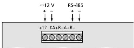
Fig. 7 Connections of the DRM-882WPX
Connect the RS-485 connections to the corresponding contacts of the jack RS-485 IN (10); the pin configuration is shown in fig. 2. The centre pair of terminals A+/ B− is designed for connection of another control panel. To supply power to the control panel, connect the control panel to a regulated, unearthed DC voltage source of 12 V (observe the correct polarity!).
Note: In order to enable the control panel to establish a data connection to the DRM-882LAN, only switch on the power supply for the control panel when the DRM-882LAN has already been switched on.
4.6.1 Setting up the control panel
The control panel DRM-882WPX provides two operating modes (chapter 5.6). To select the operating mode, to set the automatic display deactivation (standby) and to address the DMR-882LAN to be operated by remote control, call up the menu SYSTEM SETUP:
1) Keep the buttons SET (24), ESC (25) and the rotary knob (23) pressed for approx. 5 seconds. The menu SYSTEM SETUP is displayed.
2) Make the desired settings according to the menu structure shown in fig. 8.
To select the individual menu items, rotate the knob; to call them up, press the button SET; to set them, rotate the knob. To confirm a changed setting and to exit the corresponding menu item, press the button SET. To exit a menu item without making any changes, press the button ESC.
3) To exit the menu, keep the rotary knob (23) pressed until the display goes dark; the control panel is in the standby mode. To exit the standby mode, press the knob for a few seconds; the control panel will then go the operating mode selected in the mode option.
The menu provides the following setting options:
- Mode: operating mode
Master (chapter 5.6.1)
Zone (chapter 5.6.2)
- ID: unit number of the DRM-882 to be remote-controlled ( chapter 5.3.4)
- Auto Stand-by: deactivation of the display
Üri: automatic deactivation after approx. 40 seconds if the control panel is not operated
Off: no automatic deactivation
To deactivate the display at any time, keep the knob (23) pressed for a few seconds.
- Zone: if Mode = Zone has been selected, use this setting to define the output that is to be operated via this control panel
![graph TD A["SET + ESC + >5s"] --> B["SYSTEM SETUP"] B --> C["Configure Mode"] C --> D["SET → Configure Mode\nMode = Master"] D --> E["Mode = Zone"] E --> F["ESC"] F --> G["SET"] G --> H["Configure ID"] H --> I["SET → Configure ID\nID = 01"] I --> J["..."] J --> K["ID = 64"] K --> L["ESC"] L --> M["S…](/content/2026/06/1400817/images/404158e1974de27982faa2dd5d81e52678c586f0274d0215394888772787220a.jpg)
Fig. 8 System menu of DRM-882WPX
4.7 Computer
To operate the DRM-882LAN by remote control via a computer, connect the computer to the jack (5), using a USB cable.
Alternatively, the unit may also be controlled via the RS-485 interface (provided the interface is not to be used for connecting a control panel DRM-882WP/-882WPX) or Ethernet. To control the DRM-882LAN via the RS-485 interface, connect the RS-485 output of the computer to the jack RS-485 IN (10); the pin configuration is shown in figure 2. The output jack RS-485 OUT (11) may be connected to the jack RS-485 IN of an additional DRM-882LAN. Thus, up to 64 units to be controlled may be connected in a chain. If multiple units are connected and if longer control lines are used, the control output of the last unit in the chain should be equipped with a terminal resistor (120 Ω resistor between pin 1 and pin 2 of the connection) to prevent interference while signals are transmitted.
To operate the DRM-882LAN by remote control via Ethernet, the jack TCP/IP (9) may be used to connect the DRM-882LAN to an individual computer, a local computer network or, e.g. via a router, to larger computer networks (Internet). Network technology expertise is indispensable for the correct installation of the connection.
To control multiple DRM-882LANs via RS-485 or Ethernet, an individual IP address or ID number must be assigned to each unit. To assign the addresses or numbers via a computer, each unit must first be connected to the computer using a USB cable (chapter 6.2.10). Alternatively, the IP address and the ID number can be directly set at the unit by means of the system menu (chapter 5.3). If the units have been set to the DHCP mode (chapter 5.3.2), the network settings of the units can be made automatically by a DHCP server.
4.8 Mains connection
Connect the supplied mains cable to the mains jack (7) and the mains plug to a socket (230V/50Hz).
5 Operation
5.1 Switchingon/off
Prior to switching on the units connected to the outputs and the power supply of the control panel DRM-882WP/-882WPX, switch on the DRM-882LAN by means of the POWER switch (6). The firmware version (e. g.1.7) is briefly shown on the display, then the configuration that was used when the unit was switched off is loaded and its name appears on the display (2).
After usage, first switch off the units connected to the outputs, and then switch off the DRM-882LAN by means of the POWER switch.
5.2 Selecting a configuration
Press one of PRESET buttons 1–6 (3) to change between the configurations (programs) saved. While the new configuration is being loaded, the following is shown on the display (2):
Please Wait...
Loading new program...
The name of the new configuration will then appear on the display.
If the settings of the unit have been appropriately defined, the switching outputs will also be changed ( chapter 6.14 or 5.3.6).
Note: If the unit has been locked by means of the PC software (Chapter 6.17), it will not be possible to change between the configurations.
5.3 System settings
To call up the system setting menu, keep the button PRESET 5 (3) pressed for more than 5 seconds. The following will then be shown on the display (2):
SYSTEM SETUP
--- TcP/IP Setup ---
Note: If the unit has been locked by means of the PC software (Chapter 6.17), it will not be possible to call up the system menu.
Use the PRESET buttons to change the settings in the menu.
The buttons have the following functions:
- PRESET 1
To call up a submenu or confirm user input - PRESET 2
To select the previous option or menu item or reduce an input value - PRESET 3
To select the next option or menu item or increase an input value - PRESET 4
To reject an input, exit a menu or submenu - PRESET 6
To go to the next input field
The menu structure is shown in figure 9.
![graph TD A["SYSTEM SETUP"] --> B["TCP/IP Setup"] B --> C["IP = 001.000.000.001"] C --> D["IP = 223.255.255.254"] D --> E["P.2/3"] D --> F["P.4"] D --> G["P.6"] D --> H["P.6"] D --> I["P.6"] A --> J["USB/RS485 Setup"] J --> K["Mode = USB"] K --> L["RS485"] L --> M["Automatic"] M --> N["P.2/3"] A -->…](/content/2026/06/1400817/images/20e927f8ae2fc211d7abbab8ddca69857c0b5e845f215ca18f1060a2d603584b.jpg)
Fig. 9 Menu SYSTEM SETUP
To exit the menu, press the button PRESET 4 (if required several times).
Note: As long as the system setting menu is called up, the DRM-882LAN cannot be operated by remote control via a computer or a control panel DRM-882WP/-882WPX.
5.3.1 Setting the IP address
The unit requires an IP address to be operated by remote control via Ethernet. If multiple units are connected to the PC at the same time, the units must have been assigned different IP addresses for identification. The IP addresses can be assigned manually or, alternatively, automatically via a DHCP server in the network (e.g. in a router) chapter 5.3.2).
To manually set the IP address:
1) Call up the menu. The required submenu is already selected:
TCP/IP Setup
2) Use the button PRESET 1 to call up the submenu. The display shows, for example, the following:
IP = 1 9 2. 1 6 8. 0 0 0. 1 0 1
The first input field flashes.
3) Use the button PRESET 2 and the button PRESET 3 to set the desired values in the four fields and confirm each selection by means of the button PRESET 1. To go to the next input field without making any changes to the current input field, press the button PRESET 6.
4) Use the button PRESET 4 to exit the sub-menu.
Depending on the IP address set, the network mask is automatically created in accordance with the network class.
IP = 1. 0. 0. 1 to IP = 1 2 6. 2 5 5. 2 5 5. 2 5 5
⇒ network mask = FF000000h (class A)
IP = 1 2 7. 0. 0. 1 to IP = 1 9 1. 2 5 5. 2 5 5. 2 5 5
⇒ network mask = FFFF0000h (class B)
IP = 1 9 2. 0. 0. 1 to IP = 2 2 3. 2 5 5. 2 5 5. 2 5 5
⇒ network mask = FFFFFFF00h (class C)
5.3.2 DHCP
In the menu "DHCP Setup", you can define if the network settings of the unit are to be automatically configured by a DHCP server in the network or if the IP address manually set ( chapter 5.3.1) is to be used.
1) Call up the menu. The following menu item is selected:
- - - T _ CP / I _ P Setup - - -
2) Use the button PRESET 2 to select the following menu item:
- - - DhcpSetup - - -
3) Use the button PRESET 1 to call up the submenu. The display shows, for example, the following:
Dhcp = Off
4) Use the button PRESET 2 or PRESET 3 to activate (On) or deactivate (Off) automatic network setting.
5) Use the button PRESET 1 to confirm the setting and to exit the submenu, or use the button PRESET 4 to exit the submenu without making any changes to the setting.
5.3.3 Selecting an interface
The interfaces USB and RS-485 cannot be used at the same time. To select the interface:
1) Call up the menu. The following menu item is selected:
- - - T _ CP / I _ P Setup - - -
2) Use the button PRESET 3 to select the following menu item:
- - - USB / RS485 Setup - - -
3) Use the button PRESET 1 to call up the submenu. The display shows, for example, the following:
Mode = USB
4) Use the buttons PRESET 2 and PRESET 3 to select the interface desired: USB, RS485 or Automatic (if the interface used is to be recognized automatically).
5) Use the button PRESET 1 to exit the sub-menu or use the button PRESET 4 to exit the submenu without making any changes to the setting.
After the menu has been exited, the interface currently selected is indicated on the upper right of the display:
U = USB
R = RS - 485
= Automatic interface recognition
5.3.4 Unit number for RS-485
If multiple units are connected to the PC via the RS-485 interface at the same time, the units must have been assigned different unit IDs so that they can be identified. The unit number is also important when a unit is addressed by the control panel DRM-882WP or DRM-882WPX.
To set the unit number:
1) Call up the menu. The following menu item is selected:
- - - Tcp / Ip Setup - - -
2) Use the button PRESET 3 to select the following menu item:
- - - IDRS 4 8 5 Setup - - -
3) Use the button PRESET 1 to call up the submenu. The display shows, for example, the following:
ID = i
4) Use the buttons PRESET 2 and PRESET 3 to select the unit ID desired (1–64).
5) Use the button PRESET 1 to exit the submenu or the button PRESET 4 to exit the submenu without making any changes to the setting.
5.3.5 Retrieving switching combinations
The switching combinations (switch presets) may also be retrieved by means of the menu ( chapter 6.14.2):
1) Call up the menu. The following menu item is selected:
- - - Tcp / IP Setup - - -
2) Use the button PRESET 3 to select the following menu item:
- - - Out Switch Setup - - -
3) Use the button PRESET 1 to call up the submenu. The display shows, for example, the following:
SP02 S1=0 S2=1 S3=0 S4=0
In this example, switching configuration 2 with the following switching statuses has been selected:
switching output 2 = on
switching outputs 1, 3, 4 = off.
4) Use the buttons PRESET 2 and PRESET 3 to select the switching combination desired (1–10). The number of the switching combination selected flashes initially.
5) Press the button PRESET 1 to go to the combination selected.
6) Use the button PRESET 4 to exit the sub-menu.
Note: If the switching combinations are linked to configurations ( RR chapter 5.3.6), the unit will, after the system menu has been exited, automatically change to the switching combination that corresponds to the current configuration.
5.3.6 Linking switching combinations to configurations
To link the switching combinations to configurations, i. e. to retrieve the corresponding switching combination when selecting a configuration:
1) Call up the menu. The following menu item is selected:
- - - T _ CP / I _ P Setup - - -
2) Use the button PRESET 3 to select the following menu item:
- Output Switch Linked -
3) Use the button PRESET 1 to call up the submenu. The display shows, for example, the following:
Link = OFF
4) Use the button PRESET 2 or PRESET 3 to define if the switching combinations are to be linked with the configurations (ON) or not (OFF).
Each of the switching combinations 1 to 6 is linked to the configuration of the same number. The switching combinations 7 to 10 are linked to the extra configurations 1 to 4 (Chapter 6.13.5), i.e. they are retrieved via the switching inputs INPUT PORT (13).
5) Use the button PRESET 1 to exit the submenu or the button PRESET 4 to exit the submenu without making any changes to the setting.
5.4 Status LEDs
The LED PHANTOM POWER (1) lights up when the phantom power supply for the microphone inputs has been switched on.
In addition, the following eight LED groups (4) with the following functions are available:
- LIMITER – indicates that the level limiter or the compressor of the corresponding output is active
- CLIP – indicates that the corresponding output is overloaded after equalization
- SIGNAL – indicates for an output that a signal is present at an input that is assigned to this output
– FBK – indicates that feedback suppression has been selected for the microphone input - MIC – indicates that the input has been configured as a microphone input
- LINE - indicates that the input has been configured for line-level signals
5.5 Operation via DRM-882WP
The control panel DRM-882WP may be used to retrieve the first four configurations (programs) of the DRM-882LAN. In addition, the volume of all outputs can be changed.
If the two LEDs next to the buttons UP and DOWN (18) flash, connection problems may have occurred, e. g. the power supply of the control panel may have been switched on before the DRM-882LAN was switched on.
Note: For operating the DRM-882LAN via the control panel DRM-882WP, the control panel must have been set to the DRM-882LAN ( chapter 4.5.1). In addition, the DRM-882LAN must have been set to the correct interface type (RS-485 or automatic interface recognition) and the unit number (ID) must be 1 ( chapters 5.3.3 and 5.3.4).
1) If the LED UNLOCKED (17) does not light up, unlock the control panel. To do so, insert the supplied key into the lock (19), then turn the key 90 degrees to the right and back so that the LED UNLOCKED lights up.
2) To retrieve the configuration 1, 2, 3 or 4, press the appropriate PRESET button (16). The LED next to the button pressed first flashes rapidly, then flashes slowly and finally lights up continually.
3) Use the buttons UP and DOWN (18) to stepwise increase or reduce the volume of all outputs. For a continuous change, keep a button pressed.
4) If desired, use the key switch to protect the control panel against operation by unauthorized personnel. To do so, insert the key into the lock, then turn the key by 90 degrees to the right and back so that the LED UNLOCKED extinguishes.
5.6 Operation via DRM-882WPX
The functions of the control panel vary and depend on the operating mode selected during setup (chapter 4.6.1). For operation, the buttons SET (24) and ESC (25) and the rotary knob (23) are used.
1) Use the rotary knob to select a menu item.
2) Use the button SET to call up a menu item or to execute a function.
3) Use the rotary knob to set a value or to select an option.
For some parameters, the rotary knob can be pressed to change the increment.
4) Use the button ESC to exit a menu item.
5.6.1 Operating mode "Master"
The control menu of the operating mode "Master" is shown in fig. 10. The following options are available:
- Master Volume: overall volume
- Select Input: input settings Mute: muting Gain: gain Step: increment
- Select Output: output settings Mute: muting Volume: volume Step: increment
- Routing: assignment of the inputs to the output selected and setting of the signal
mixing ratio
Mute = Off: input assigned
Mute = On; input not assigned
Gain: signal part of the input for this output
- Load Program: loading of a configuration saved in the router
- Info: display of system information
- Lock: locking of the control panel to protect it against accidental operation To unlock the control panel, keep the buttons SET and ESC pressed for more than 5 seconds.
![graph TD A["DRM-882WPX PANEL"] --> B["Master Volume"] B --> C["SET→ Master Volume [dB"]] C --> D["Step=1.0dB U=0.0"] D --> E["Step=0.idB U=-127.0"] E --> F["ESC"] F --> G["Select Input"] G --> H["SET→ Select Input"] H --> I["Input 1"] I --> J["Input 8"] J --> K["ESC SET SET Mute → Mute = Off ON"] K…](/content/2026/06/1400817/images/70d8b4cf3552ad9ba8a5e88dd8799488b28e29a758a5d88bde6e7eb3c74c338b.jpg)
Fig. 10 DRM-882WPX - control menu "Master Mode"
![graph TD A["Select Routing"] --> B["SET→ Select Routing"] B --> C["Input 1"] C --> D["Input 8"] D --> E["ESC SET-SET Mute - → Mute = Off ON"] E --> F["Gain -SET→ Gain [dB"]] F --> G["G = 0"] G --> H["G = -39"] H --> I["ESC"] I --> J["Zone Control"] J --> K["SET→ Zone X"] K --> L["Mute -SET→ Mute = O…](/content/2026/06/1400817/images/2a1eaa5dcb40f0bef8faa85a930687bde434ed7f5b6c704d23c25ad0170f186a.jpg)
Fig. 11 DRM-882WPX – control menu "Zone Mode"
5.6.2 Operating mode "Zone"
The control menu of the operating mode "Zone" is shown in fig. 11. The following options are available:
- Select Routing: assignment of the inputs to the output X defined during setup and setting of the signal mixing ratio
Mute = Off: input assigned
Mute = On: input not assigned
Gain: signal part of the input for this output
- Zone Control/Zone X:
settings for output X
Mute: muting
Volume: volume Step: increment
- Info: display of system information
- Lock: Locking of the control panel against accidental operation
To unlock the control panel, keep the buttons SET and ESC pressed for more than 5 seconds.
5.6.3 Standby mode
In the standby mode, the display is deactivated and the control panel is protected against accidental operation.
To call up and exit the standby mode, keep the rotary knob (23) pressed for more than 5 seconds.
Note: An automatic change to the standby mode can be defined during setup ( Chapter 4.6.1).

Fig. 12 Main window
6 Remote Control via a Computer
The computer software supplied can be used to operate the DRM-882LAN by remote control. Thus, the unit may also be configured for operation without a computer. The configurations created may be saved on the unit and on the computer.
Note: If the DRM-882LAN is connected to a control panel DRM-882WP/-882WPX, make sure that the control panel is not operated while the DRM-882LAN is remote-controlled via a computer [e. g. lock the control panel]. Otherwise, connection conflicts might occur.
6.1 Installing PC Software
The installation of the control program supplied requires a PC equipped with the Windows XP operating system (SP2) or later, a memory of at least 512 MB, 10 MB free hard-disk space and a USB, Ethernet or RS-485 interface. The screen resolution should be at least 1024 x 768 pixels. To install the PC software, start the installation program SetupDRM-882LANv...EXE on the CD supplied and follow the instructions of the installation program.
Windows is a registered trademark of Microsoft Corporation in the United States and other countries.
6.1.1 Installing an interface driver
The connection via the USB interface or the Ethernet interface requires a special driver which is included on the CD supplied. Call up the file USB[...]SETUP.EXE to install the driver automatically. The driver will simulate a serial interface for the operating software.
6.2 Starting the PC software
Start the control program DRM-882LAN V...EXE on the PC. The main window (fig. 12) appears, showing the units that were most recently connected. For each unit, a separate window is provided: the header shows information with regard to the interface as well as the connection status.
6.2.1 Adding units
To add a(nother) unit, click the button "Add Device".
If USB is selected as the current interface type (the text on the button on the upper left is "USB-COMx"), the following unit window will be displayed:
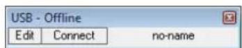
Fig. 13 USB unit window
After that, it is not possible to add further units.
If RS-485 is selected as the current interface type (the text on the button on the upper left is "RS485-COMx"), the following dialog window will initially be displayed:
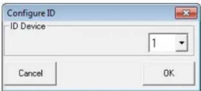
Fig. 14 Selection of unit number (ID)
Select the unit number (ID) of the unit desired and then press "OK" to confirm (setting the ID of a unit 6.2.10 or 5.3.4).
If Ethernet is selected as the current interface type (the text on the button on the upper left is "TCP/IP"), the following dialog window will initially be displayed:
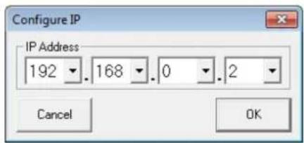
Fig. 15 Selection of IP address
Enter the IP address of the unit desired and then press "OK" to confirm (setting the IP address of a unit ➡ chapter 6.2.10 or 5.3.1). If the IP address of the unit is not known, use the function "IP Search" to search the network for units connected ( ➡ chapter 6.2.2). For each unit, a separate window is added.
6.2.2 Searching the network for units
To search the network for connected units, call up the window shown in fig. 16 by means of the button "IP Search".
Note: The function is only available when the interface "TCP/IP" has been selected.

Fig. 16 Window "IP Search"
1) Under "Scan the following IP range", define the address range to be searched.
Under "Host Address", the current IP address of the computer is shown. This address should be in the same subnet range as the addresses of the units to be controlled.
2) Click "Scan" to start searching.
The IP addresses of the units found in the network are listed under "Device(s) found".
3) Tick the boxes next to the addresses of the units desired.
4) Click "Add device(s) to Project" to add the units selected.
6.2.3 Connecting or disconnecting units
To establish a data connection to the unit, click the button "Connect" in the window of the unit desired (cf. fig. 12). Instead of the unit name or "no-name" (if no name was assigned to the unit), a status bar is shown indicating the progress of the connection establishment. Once the connection has been established, the button "Connect" is replaced by the button "Disconnect".
To connect all units, use the button "Connect All" located in the upper button bar of the main window.
If a connection establishment fails and an error message is displayed (e.g. "COM not found", "Devices disconnected" or "IP address: x.x.x.x not found"), this may be due to the following reasons:
- a wrong unit number/ IP address has been set ( chapter 5.3.4, 5.3.1 or 6.2.10)
- a cable connection is defective
- a unit is not switched on or its system menu is called up (chapter 5.3)
- the wrong interface has been selected in the system menu (chapter 5.3.3)
– the network settings on the computer are not correct (for connection via Ethernet)
The display of a connected unit shows the following (example):
System Lock PC Connection
or
System Lock Online Device ID [01]
or, if controlled via Ethernet
System Lock
IP: 192.168.001.101
The unit cannot be directly operated as long as the connection exists.
To disconnect the data connection, click the button "Disconnect" in the window of the unit desired and then confirm the confirmation message. Then, the DRM-882LAN can directly be operated again.
It is not possible to disconnect the connection while the configuration window of a unit is still open.
6.2.4 Naming a unit
The units may be named for easier identification in the main window. The default name is "no-name". To change a unit name, double-click the current name. A dialog window appears. Overwrite the old name with the new name (max. 16 characters) and then click "OK" to confirm your changes or "Cancel" to cancel.
6.2.5 Calling up the configuration window
To operate a connected unit by remote control and to change its configuration, click the button "Edit" in the window of the unit (cf. fig. 12). The configuration window for the unit is displayed (fig. 18). The operating options provided by the configuration window are described in detail from chapter 6.3 onwards.
The configuration window may also be opened when the unit is not connected. Thus, it is possible, for example, to view and edit configurations saved on the computer without the need of a unit. To connect the unit, first exit the configuration window ( Chapter 6.18).
6.2.6 Removing units
To remove a unit from the constellation, close the corresponding unit window (☒) and then confirm the confirmation message.
To remove all units, click the button "Remove Device" located in the upper button bar of the main window. Then confirm the confirmation message.
6.2.7 Saving a unit constellation
The unit constellation currently created in the main window along with the unit names and the interface type may be saved as a "project" on the computer.
1) Click the button "Save Project". The dialog window "Save As" is displayed.
2) Enter the file name desired, select the location where the file is to be saved and then save the file.
By default, the subfolder "Project" is selected which was automatically created during program installation. The file extension *.p88 is automatically appended to the file name entered.
6.2.8 Loading a unit constellation
To load a unit constellation that has been saved on the computer:
1) Click the button "Load Project" located on the upper right of the window. The dialog window "Open" is displayed.
2) Select the file desired and then confirm your selection.
If the interface used by the constellation selected is different from the interface currently set, a warning message will appear. To go to the interface of the constellation, confirm the message.
6.2.9 Changing the interface
To change to one of the other interface types supported, first remove all units from the main window (Chapter 6.2.6).
1) Click the button on the upper left. Depending on the interface currently selected, the text on the button is "USB-COMx", "RS485-COMx" or "TCP/IP".
The following dialog window is displayed:
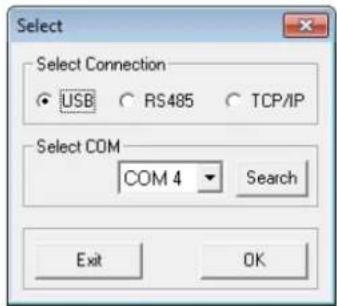
Fig. 17 Window "Select Connection" – USB
2) Under "Select Connection", select the interface desired ("USB", "RS485" or "TCP/IP").
3) For "RS485", the number of the port used for this interface must be selected under "Select COM". For "USB" (fig. 19), the serial interface that simulates the driver for this software must be selected under "Select COM". Check the settings of the operating system for the appropriate COM interface or use the button "Search" to have it determined automatically.
The corresponding settings of the operating system can be found under "Device Manager ⇒ Ports (COM & LPT).
There, the following is shown (example):

If there are conflicts with other units, the number of the COM interface may be changed here.
Note: To avoid communication problems, it is recommended to manually change the COM numbers 10 and higher that are automatically assigned by the computer to the COM numbers 1 to 9.
![graph TD A["Input Line1"] --> B["InP1"] B --> C["Line1"] C --> D["InP2"] D --> E["Line2"] E --> F["InP3"] F --> G["Line3"] G --> H["InP4"] H --> I["Line4"] I --> J["InP5"] J --> K["Line5"] K --> L["InP6"] L --> M["Line6"] M --> N["InP7"] N --> O["Line7"] O --> P["InP8"] P --> Q["Line8"] style A fill…](/content/2026/06/1400817/images/8daa98b93b5907fe24f0e4f294c6cf95deee29ce194adc75e21d5710802d592e.jpg)
Fig. 18 View "Overview"
![IP-192.168.0.2 DRM-802LAN - Program load from device - 04:4 S6 StereoLOUD Status: Online Inputs Cut Cut Out Dut Out Dut Dut Dut Dut Overview Overview Input1 Gain [dB] 0 dB 0 50% 0 50% 0 50% 0 50% 0 50% 0 50% 0 50% 0 50% 0 50% 0 50% 0 50% 0 50% 0 50% 0 50% 0 50% 0 50% 0 50% 0 50% 0 50% 0 50% 0 50% Ga…](/content/2026/06/1400817/images/728850d634e69a44fd13d2a8f071085000741131be7d5d707ed17acb5e7a5686.jpg)
Fig. 19 View of the input channels "Inputs"
6.2.10 Setting the ID number or the IP address
To operate multiple DRM-882LAN by remote control via RS-485 or TCP/IP, a separate ID number or IP address must be assigned to each unit prior to their first simultaneous operation. This may be done in the system menu (chapter 5.3.1 or 5.3.4) or, as described in the following, via the computer.
Connect the units one after another to the PC, using the USB interface, and make the following settings for each unit:
1) If the USB interface has not been selected, use the main window to go to the USB interface (chapter 6.2.9).
2) Add a unit (button "Add device", chapter 6.2.1).
3) Connect the unit (button "Connect", chapter 6.2.3).
4) Click the button "ID & IP" that is now available. The following dialog window is displayed:

Fig. 20 Window "Configure ID-RS485 and IP Address"
5) For remote control via RS-485, select an ID number (1–64) under "Select new ID". Note: If, after its configuration, a DRM-882LAN is not to be controlled via the computer but via the control panel DRM-882WP, make sure that the ID of the DRM-882LAN is set to 1. If the DRM-882LAN is to be controlled via the control panel DRM-882WPX, its ID number can be set as desired.
For remote control via Ethernet, define an IP address under "Select new IP Address". A network mask will automatically be generated (chapter 5.3.1). If the IP address is to be assigned automatically by a DHCP server in the network, tick the option "dhcp" (chapter 5.3.2).
6) Click "OK" to confirm or "Cancel" to cancel.
7) Use the button "Disconnect" to disconnect the data connection and then confirm the confirmation message. If desired, connect another DRM-882LAN to the USB port of the computer and continue with step 3.
Then go to the interface desired for controlling and configuring the units (chapter 6.2.9).
6.2.11 Exiting the program
Use the button "Exit" or the icon ☒ in the upper right corner to exit the program. Then confirm the confirmation message.
6.3 Views
In the configuration window of a unit, the user can switch between the views that are represented by tabs: "Overview", "Routing", "Inputs" and the settings for each output channel. When a unit window is opened, the view "Overview" (fig. 18) is initially displayed. It provides a quick overview of the configuration: the left-hand side shows the eight input channels, and the right-hand side shows the eight output channels. The lines in between represent the assignment of the outputs to the inputs. Click one of the function blocks in the diagram to go to the corresponding view.
The icon indicates that the respective input channel or output channel has been muted.
6.3.1 Unit for signal delay
The signals of all inputs and outputs can be individually delayed. This is useful, e. g. when speakers are not equally distant from the listener. To balance the different sound delay times that arise from the different distances, the signal of the speaker located close to the listener is delayed so that it will not reach the listener earlier than the sound of the more distant speaker.
The user does not need to calculate the sound delay time, i. e. the user can enter the distance instead of the delay time. The calculations performed by the system are based on a speed-of-sound value of 340 m/s.
In the view "Overview" (fig. 18), under "Delay" (upper left of the view), define if the delay is to be entered as a time value (Time) or a distance value (Meter). The setting defined will apply to all outputs and may be changed at any time.
6.4 Configuring inputs
The signals of the inputs may already be processed before they are actually split to the outputs. While being processed, the signals take the processing path shown in figure 5. To configure the inputs, select the view "Inputs" (fig. 19) which provides a clearly arranged overview of the most important parameters of all inputs.
Inputs may be linked ( chapter 6.10) so that multiple inputs can simultaneously be set to the same values. In addition, it is possible to link input channels in pairs to create stereo channels so that stereo signal sources can be used ( chapter 6.4.4).
6.4.1 Selecting the signal level
Use the list field "Mic / Line" (fig. 19) to define if the signal source provides a microphone level (Mic) or a line level (Line). On the right-hand side, under "Input Linked", the corresponding field turns yellow (Mic) or green (Line).
Note: When a channel is linked to its adjacent channel to create a stereo channel, the option "Mic" cannot be selected ( chapter 6.4.4).
6.4.2 Selecting the signal transmission type
A tick in the box "Balanced" indicates that a balanced signal is present at the corresponding input. For an unbalanced signal, click the tick to remove it. The signal level will then be increased by 6 dB.
6.4.3 Phantom power supply
Tick the box "Phantom" to supply all inputs defined as microphone inputs (chapter 6.4.1) with a phantom power of 48 V. Some microphones require this phantom power supply for operation.
CAUTION

Signal sources with unbalanced signal outputs may be damaged by the phantom power supply.
Make sure that no phantom power is supplied to inputs with unbalanced signals (e.g. by inadvertent switchover to another configuration).
6.4.4 Linking inputs as a stereo pair
Input channels can be linked in pairs to create a stereo channel; thus, it is not necessary to make all settings at both input channels when stereo signal sources are used. To link input channels, tick the box "Stereo Mode" located above the channel settings (fig. 21). A message will appear to inform you that the channel with the higher channel number will adopt all settings of the channel with the lower channel number.
When channels have been linked as a stereo pair, any change to the settings of one of the two channels will apply to both channels. The channel names will be automatically changed, e. g. from "Inp7" and "Inp8" to "Inp7-L" and "Inp7-R".
Note: Inputs can only be linked as a stereo pair when the signal level of both channels has been set to "Line" (Chapter 6.4.1).
![IP-192.168.0.2 DRM-882LAN - Pro Inputs Out1 Out2 Stereo Mode ✓ Inp1 Gain [dB] 0 dB 0 dBu dBu Inp2 Gain [dB] 0 dB 0 dBu](/content/2026/06/1400817/images/6b74f3fa2f33fc9ad07136b85283570c726a150a2cf371b2718bbd7857ff91f0.jpg)
Fig. 21 Linking inputs as a stereo pair
6.4.5 Gain
The input gain can be adjusted to values between -127 ... +12 dB. To change the gain, move the slider under "Gain" by means of the mouse, or (with the slider selected) use the arrow keys or the "Pg Up" or "Pg Down" keys on the keyboard. To quickly reset the gain to 0 dB, click the button "0 dB" above the slider. To temporarily adjust the gain to 0 dB, click the button "Byp"; the button will appear in red. To reset the gain to the value that has been adjusted by means of the slider, click the button again.
6.4.5.1 Main control "Master Input Gain"
To change the input gain of all inputs at the same time, adjust the control "Master Input Gain". Unlike the adjustment made for linked inputs (Chapter 6.10), this will not adjust all controls to the same values – only the gain values will be proportionately reduced in accordance with the adjustment of the main control.
6.4.6 Noise gate
A signal can only pass a noise gate when the signal level exceeds an adjustable threshold value. Signals with a level below this threshold value will be attenuated so that they are not audible. This can, for example, be used to suppress the noise floor of a signal source or the crosstalk of other audio sources when sound is picked up with multiple microphones.
To activate the noise gate of an input, tick the box "Enable" under "Noise Gate". In the status display, "Input Off" will indicate the channels that are suppressed by means of the noise gate (fig. 31 in chapter 6.8).
To set the parameters, click "Edit". The noise gate window is shown (fig. 22). There, the following parameters can be set:
- Thr: threshold value; the noise gate will open when the signal exceeds this value
- Attack: attack time
- Release: time after which a signal will be attenuated when its level has fallen below the threshold value
When all settings have been made, click ☒ in the upper right corner to exit the window.
![Noise Gate - Inp1 -76 10 1 Thr [dBu] Release Attack Enable ✓](/content/2026/06/1400817/images/1b63d682802708124fac7d5d2dca35bdfe053651a25da804609da37520f289bf.jpg)
Fig. 22 Noise gate
6.4.7 Sound adjustment
Each input provides a basic filter (Filter 1st order) and an equalizer (EQ) offering a wide range of sound adjustment options. For microphone inputs, equalization is only available as an alternative to feedback suppression.
To set the basic filter:
1) In the list field, under "Filter 1st order" (fig. 23), select the filter type: "High Pass" or "Low Pass".
To deactivate the filter, select "Bypass".
2) Set the cut-off frequency in the field under the list field.

Fig. 23 Input filter
If the signal level "Mic" was selected for an input, the option "EQ" must be selected under "Sel Fbk / EQ" so that the equalization function can be used.
To adjust the equalization, click the button "Edit" under "EQ". The window "Inputs EQ" (fig. 24) is displayed, indicating the sound adjustments for the input selected. Use the tabs in the upper section of the window to select other inputs.
Under "EQ", the 3 independent filters of the input channel can be adjusted (fig. 25). The following filter types are available:
Peaking_Eq / PEAK EQ (Peaking Equalizer) Filter with bell characteristic with adjustable gain/attenuation (dB), center frequency (Hz) and quality factor (Q)
Hi-Shelv_Q / HiSHF Q (High Shelving Filter Q) Symmetric high frequency filter with shelving characteristic For the adjustable cut-off frequency (Hz), the level is half of the gain /attenuation adjusted (dB); the slope depends on the adjustable quality factor (Q).
Lo-Shelv_Q / LoSHF Q (Low Shelving Filter Q) Symmetric low frequency filter with shelving characteristic For the adjustable cut-off frequency (Hz), the level is half of the gain /attenuation adjusted (dB); the slope depends on the adjustable quality factor (Q).

Fig. 25 "EQ"
1) Use the upper button (here, "PEAK EQ") to call up a dialog window, and then select the filter type.
2) Use the slider to adjust the level boosting or the level attenuation.
3) In the field "Hz" beneath the slider, enter the filter frequency.
4) Enter the filter quality factor (Q) or the relative bandwidth value (Bw) in the corresponding field or set them by clicking the arrows beneath the fields. Numbers entered will be rounded to the nearest value possible.
5) To deactivate individual filters, click the button "Byp". The button will appear in red. To activate the filter, click the button again.
6) To reset the gain values (0 dB) of all filters of the input, click the button "Flat Eq". In the dialog window "Flat Eq – Are you sure?" that appears, confirm or cancel the procedure.
7) Use the button "Exit" to exit the equalization function.
Note: Alternatively, the level boosting/attenuation and the filter frequency can also be adjusted graphically (Chapter 6.4.7.1).
6.4.7.1 Frequency response
The diagram indicates the frequency response of the input channel, depending on the equalization adjustment.
In the upper right of the diagram, the type of representation can be selected: magnitude frequency response ("Mag") or phase frequency response ("Phase").
Click the button "Show cursor" to show a graphical reference point (1, 3) next to the curve for each filter (fig. 24). Use the mouse to move the reference points and thus to graphically adjust the frequency and the level boosting / level attenuation of the filters.
Click the button "Show cursor" again to hide the reference points.

Fig. 24 Window of the input equalization "Inputs EQ"
6.4.8 Feedback suppression (FBK)
If the signal level "Mic" has been selected for an input, the function "FBK" under "Sel Fbk / EQ" may be used (fig. 19) instead of the equalization function. The function "FBK" is an effective algorithm based on a frequency shift for feedback suppression that allows users to adjust higher volumes for speech applications without having any interfering howling sounds.
Use the slider "Feedback dev freq [Hz]" to adjust the level of the frequency shift: the higher the value, the more effective the feedback suppression.
6.4.9 Phase reversal
The signal of the input can be reversed. This may, for example, counteract phase cancellations that occur when two microphones are located in different directions to / distances from the same sound source. A tick in the box "Phase 180°" indicates that the signal is reversed. Click the box to deactivate the phase reversal function.
6.5 Configuring outputs
The signals of all outputs take the processing path shown in figure 6. The view "Routing" is used to assign the input signals to the outputs; the other settings of the outputs, however, are defined in a separate view for each output channel.
Outputs may be linked (chapter 6.10) so that multiple outputs can simultaneously be set to the same values.
6.5.1 Assigning/Mixing inputsignals
1) To assign the desired input signals to each output and to define their mixing ratio, select the view "Routing" (fig. 26).
2) Use the matrix "Output Routing" to select the input signals that are to be assigned to an output channel. Each row of the matrix represents an input channel, and each column represents an output channel. Click a node to assign an input to an output (the square located at the node will appear in red) or to remove the assignment.
3) Use the slider under "Editing mix routing" to attenuate the level for each assigned input signal by up to 30 dB (the attenuation will only apply to this output channel). Thus, different signal mixing ratios for the outputs can be defined. Clicking a node in the matrix will automatically select the control group of the corresponding output; alternatively, the output may also be selected by means of the buttons "Output Selected".
4) To remove all assignments, click the button "Reset" and then confirm the confirmation message.
Colour lines in the view "Overview" (fig. 18) indicate the channel assignments.
6.5.2 Signal delay
Each output signal may be delayed by up to 380.998 ms. Thus, different sound delay times due to different speaker distances may be balanced.
In the view of an output (e. g. "Out7", fig. 27), under "Delay", set the delay for the output signal. The unit (meter or milliseconds) can be changed in the view "Overview" (Chapter 6.3.1).
To change the delay value, click the arrows next to the input field. Use the arrows above "Adj" for a coarse adjustment and the arrows above "Fine" for a fine adjustment. Alternatively, enter the value in the field. The value entered will be rounded to the nearest value possible.
Use the button "Bypass" beneath the value field to temporarily deactivate the delay; the button will appear in red. To activate the delay, click the button again.
6.5.3 High pass filter and low pass filter
Each output is provided with a high pass filter and a low pass filter that, in combination, may assume the function of a crossover network (for frequency-dependent splitting of an input signal to two or more output channels).
In the view of an output (e.g. "Out7", fig. 27), under "High Pass Filter" and "Low Pass Filter", set the high pass filter and low pass filter desired.
1) Under "High Pass Filter", in the field "Slope", select one of the eight filter characteristics or "Bypass" to bypass the high pass filter. The following filter characteristics are available:
Buttw -6 dB
Butterworth filter of first order with a slope of 6dB/octave
Buttw -12 dB
Butterworth filter of second order with a slope of 12dB/octave
LRiley -12 dB
Linkwitz-Riley filter of second order with a slope of 12 dB / octave
Bessel -12 dB
Bessel filter of second order with a slope of 12dB/octave
Buttw-18dB
Butterworth filter of third order with a slope of 18dB/octave
Buttw -24 dB
Butterworth filter of fourth order with a slope of 24dB/octave
LRiley -24 dB
Linkwitz-Riley filter of fourth order with a slope of 24dB/octave
Bessel -24 dB
Bessel filter of fourth order with a slope of 24dB/octave
2) Under "Low Pass Filter", in the field "Slope", select one of the eight filter

Fig. 26 View "Routing"
![IP:192.168.0.2 DRM-B5ZLAN - Program load from device - 04:4 S6 StereoLOUD Status: Online Type: Cut Out Cut Cut Cut Cut Cut Select Control High Pass Filter Freq [Hz] 20 Slope Bypass Low Pass Filter Freq [Hz] 20000 Slope Bypass Delay [m] 0 A/Q Bypass Fine EQ L/32F PEAK PEAK PEAK PEAK 8 0 0 4 10 40 100…](/content/2026/06/1400817/images/15048e40548d4438f2af12bea097ce5ca5a386fca33a6917d9f4bdf4cb774911.jpg)
Fig. 27 View of output channel "Out7"
characteristics or "Bypass" to bypass the low pass filter.
3) In the fields "Freq [Hz]", enter the cut-off frequency desired.
The settings are also reflected in the frequency diagram (chapter 6.5.4.1).
6.5.4 Equalization
For the equalization of the individual outputs, five independent filters are provided. Set these filters in the view of an output (e.g. "Out7", fig. 27) under "EQ". The procedure for setting the equalization filters is identical to that for setting the input channel filters (Chapter 6.4.7).
6.5.4.1 Frequency response
The diagram in the upper section of the window indicates the frequency response of the output channel, depending on the equalization and gain ( chapter 6.5.6) that have been set.
On the right-hand side of the diagram, the type of representation can be selected: magnitude frequency response ("Mag") or phase frequency response ("Phase"). If "Mag" is selected, the field beneath "Step dB" may be used to select the scaling and the field beneath "Offset dB" to select the vertical shift of the diagram. To change a value, click the up or down arrow buttons next to the field.
For graphical adjustment of the filters, the reference points (☐, ☐, ☐, ☐, ☐) may be shown [identical to the procedure for the equalization filters of the inputs (☐ chapter 6.4.7.1)].
6.5.5 Compressor
The compressor reduces the dynamic range and attenuates the level above an adjustable threshold. This is necessary if the dynamic range of the audio signal is higher than allowed by the amplifier system or the listening situation (e.g. in case of background music). It is also possible to reduce level differences (e.g. for changing microphone distances) or to attenuate signal peaks in order to allow a higher gain setting and thus obtain a higher average volume.
The compressor responds to the effective value (RMS) of the signal. The activity of the compressor is indicated by the LED LIMITER (4) for each output channel.
In the view of an output (e.g. "Out7", fig. 27), under "RMS Compressor", set the parameters for the compressor. To change a parameter, move the corresponding slider by means of the mouse, or (with the slider selected) use the arrow keys or the "Pg Up" or "Pg Down" keys on the keyboard.
1) Use the slider "Threshold [dBu]" to adjust the threshold value. If this threshold value is exceeded, the gain will be reduced.
2) Use the slider "Ratio [In : Out]" to adjust the compression ratio. For example, a compression ratio of 10 : 1 means that with an input level increase of 20 dB above the threshold value, the output level will only be increased by 2 dB.
3) Use the slider "Attack [ms]" to adjust the attack time.
4) Use the slider "Release [sec]" to adjust the release time, i. e. the time it takes for the gain to reach its original value after the signal level has fallen below the threshold value.
5) Use the slider "S / H Knee [%]" to define if the change to the compression is to be made abruptly (0 % = Hard Knee) or with a transition range (100 % = Soft Knee). The value defines the size of the transition range.
6) To bypass the compressor, click the button "Bypass". The button will appear in red. To activate the compressor, click the button again.
Click the button "RMS Compressor" to call up the window "RMS Compressor & Peak Limiter ..." (fig. 28). This window provides the same sliders for adjusting the parameters and the button "Bypass" for bypassing the compressor. In addition, it includes graphics that represent the signal level of the compressor input and compressor output, depending on the compressor adjustments. Any changes to the parameters "Threshold", "Ratio" or "Soft / Hard Knee" will be instantly reflected in the graphics.
6.5.6 Gain
In the view of an output (e. g. "Out7", fig. 27), under "Lev [dB]", set the gain, i. e. the output level (between -127 ... +18 dB). To change the gain, move the slider by means of the mouse, or (with the slider selected) use the arrow keys or the "Pg Up" or "Pg Down" keys on the keyboard. To quickly reset the gain to 0 dB, click the button "0 dB" beneath the slider.
To temporarily adjust the gain to 0 dB, click the button "Bypass Level"; the button will appear in red. To reset the gain to the value that has been adjusted by means of the slider, click the button again.
6.5.7 Limiter
The limiter allows the user to quickly limit the signal to an adjusted level. This prevents overloads in subsequent units (e.g. power amplifiers) and protects the speakers against damage. The limiter operates similar to the compressor de scribed above. However, while the compressor still allows an increase of the output level above the threshold value depending on the compression rate adjusted, the threshold value of the limiter defines the definite upper limit of the output signal (compression ratio = ∞ : 1).
The limiter responds to the peak values of the signal. The activity of the limiter is indicated by the LED LIMITER (4).
In the view of an output (e.g. "Out7", fig. 27), under "Peak Limiter", adjust the parameters for the limiter. To change a parameter, move the slider by means of the mouse, or (with the slider selected) use the arrow keys or the "Pg Up" or "Pg Down" keys on the keyboard.
1) Use the slider "Threshold [dBu]" to adjust the threshold value, i.e. maximum output level. If this threshold value is exceeded, the gain will be reduced.
2) Use the slider "Attack [ms]" to adjust the attack time.
3) Use the slider "Release [sec]" to adjust the release time, i. e. the time it takes for the gain to reach its original value after the signal level has fallen below the threshold value.
4) To bypass the limiter, click the button "Bypass". The button will appear in red. To activate the limiter, click the button again.
Click the button "P. Limiter" to call up the window "RMS Compressor & Peak Limiter ..." (fig. 28). This window provides the same sliders for adjusting the parameters and the button "Bypass" for bypassing the limiter. In addition, it includes graphics that represent the signal level of the limiter input and the limiter output, depending on the limiter adjustments. Any changes to the parameter "Threshold" will be instantly reflected in the graphics. Beneath the curve, the maximum level [dBu] adjusted by means of the slider "Threshold" and the corresponding peak voltage [Vp] are shown.
![| Metric | Value | |--------|-------| | RMS Compressor INPUT [dBu] | -40 | | RMS Compressor Cmp [dB] | 10 | | Peak Limiter INPUT [dBu] | -40 | | Peak Limiter Lim [dB] | 15 | | Ratio Ratio [In:Out] | -40 | | Ratio Ratio [In:Out] | -30 | | S/B Knee [%] | -20 | | S/B Knee [%] | -10 | | Release [sec] |…](/content/2026/06/1400817/images/1f6ee2d82f170aaf8c71a0e3a82eca539c4e49208440048b805b042f76195f29.jpg)
Fig. 28 Window "RMS Compressor & Peak Limiter"
6.5.8 Phase reversal
The signal of an output can be reversed, e. g. to balance a reverse polarity when connecting the speakers. A tick in the box "Phase 180°" indicates that the signal is reversed. Click the box to deactivate the phase reversal function.
6.5.9 Main control
To change the output levels of all output channels proportionately, use the slider "Master Output Volume [dB]" located at the bottom of the dialog window.
6.6 Automixer
Sometimes multiple microphones are required, but only one is used at a time, e. g. in discussions. Due to the large number of open microphone channels, there will be a high level of background noise. This noise can be quite annoying. The noise gate ( chapter 6.4.6) can be used to suppress low-level noise from each microphone channel. For this, however, the noise gate of each channel must be accurately adjusted.
The function "Auto Mixer" is an additional option. Once you speak into one of the microphones involved, this microphone will be temporarily the master microphone. The levels of all other microphones will be attenuated.
To activate the automixer function, go to the view "Overview" (fig. 18) and tick the box "Active" under "Auto Mixer". To set the parameters, click "Edit parameter". The automixer window (fig. 29) is shown. There, the operating mode of the automixer can be selected:
With the operating mode "N.O.M.", the attenuation of the input channels will depend on the number of open microphones. The attenuation range is between 3 dB (two open microphones) and 9 dB (eight open microphones).
With the operating mode "Gain Sharing", the total gain of all input channels will be kept at a constant value. The highest gain will be assigned to the channels with the highest signal level; the gain of the other channels will be reduced accordingly. The gain is calculated in a way that makes sure that the volume of the signal sum is such as if only a single microphone channel is open.

Fig. 29 Automixer
6.7 Ducker
Another option to improve speech intelligibility is to give specific channels priority over other channels. Thus, background music can be automatically suppressed while announcements are being made.
To select the priority channels, go to the view "Overview" (fig. 18) and tick the appropriate boxes "Priority Input Channel" under "Ducker". Then click "Confirm" to confirm your selection.
To edit the parameters, click "Edit parameter". The ducker window (fig. 30) will be shown. There, the following parameters can be set:
- Gating Thr: threshold value for the signal level of the priority input channels; when the level is exceeded, the other input signals will be attenuated
- Attack Time: attack time
- Hold Time: time for which the signals of the non-priority input channels will remain attenuated after the signals of the priority input channels have fallen below the threshold value "Gating Thr"
- Release Time: time after which the attenuation of the signals of the non-priority channels will be deactivated after the "Hold Time" has elapsed
- Attenuation Level: attenuation level
When all settings have been made, click ☒ in the upper right corner to exit the window.
![Ducker edit parameters Priority Input Channel 1 2 3 4 5 6 7 8 Contin Parameters 30 11 3 -40 -74 Hold Time [ms] Release Time [ms] Attack Time [ms] Gateing Thr [dB] Attenuation Level [dB]](/content/2026/06/1400817/images/24f0b245e5a30b1815a445c3c6a45fd98bebdd62216c969100f563057b6f1fdb.jpg)
Fig. 30 Ducker
6.8 Status display
Regardless of the view selected, the indicators and controls on the right-hand side of the window are always available. They show the status and adjustments of the channels (fig. 31) just like the status LEDs (4) on the unit (Chapter 5.4).
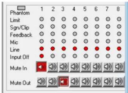
Fig. 31 Status display and muting
6.9 Muting
Use the buttons "Mute In" to mute the inputs, and use the buttons "Mute Out" to mute the outputs (fig. 31). To mute or unmute a channel, click the appropriate button of the respective channel. When a channel is muted, the corresponding button appears in red and the icon ☒ shown in the view "Overview" (fig. 18) for this channel.
6.10 Linking channels
If specific parameters for multiple outputs or inputs are to be simultaneously adjusted to the same values, the inputs or outputs may be linked while the adjustments are being made. Thus, the parameters changed for one output will be adjusted accordingly for all outputs linked. Likewise, any changes made to one input will apply to all input channels linked. Only the parameters changed while the linkage was active are adopted by the other channels. All individual adjustments of the inputs or outputs are maintained.
To link input channels:
1) On the right-hand side of the window, under "Input Linked" (fig. 32), click the buttons of all the inputs whose parameters are to be adjusted to the same value. The buttons appear to be "pressed" and the colour of their marking changes to blue.
These buttons are also available in the window "Inputs EQ" for input equalization (fig. 24).
2) To remove the link for an input, click the button of this input again.
To link output channels:
1) On the right-hand side of the window, under "Output Linked" (fig. 32), click the buttons of all the outputs whose parameters are to be adjusted to the same value. If a view for a specific output (fig. 27) is being displayed, click the button for this output as well. The buttons appear to be "pressed" and the colour of their marking changes to blue.
The linkage will be maintained even when another view is selected.
2) To remove the link for an output, click the button of this output again.
![graph TD subgraph Input Linked Inp1["Inp1"] --> Inp2["Inp2"] Inp3["Inp3"] --> Inp4["Inp4"] Inp5["Inp5"] --> Inp6["Inp6"] Inp7["Inp7"] --> Inp8["Inp8"] end subgraph Output Linked Out1["Out1"] --> Out2["Out2"] Out3["Out3"] --> Out4["Out4"] Out5["Out5"] --> Out6["Out6"] Out7["Out7"] --> Out8["Out8"] en…](/content/2026/06/1400817/images/da77acf6a28731edf7e6ec4ef0be12ac603dba2894904413962679fba11546d1.jpg)
Fig. 32 Linkage of inputs and outputs
Linking will have no effect on the following functions: "Mute In", "Mute Out", and the channel assignments "Output Routing" and "Output mix level" or "Balanced" (input signal).
6.11 Copying adjustments
In contrast to channel linking which only synchronizes the parameters changed while the channels are linked, the copy function copies all adjustments of a channel to another channel. The copy function does not apply to the following adjustments: "Mute In", "Mute Out" and the channel assignments "Output Routing" and "Output mix level" or "Balanced" (input signal).
6.11.1 Copying adjustments of an input
1) Click the button "Input Copy". The dialog window "Input Copy" is displayed.
2) Under "Input Source", select the input whose adjustments are to be copied.
3) Under "Input Destination", select the input that is to adopt the adjustments to be copied.
4) Click "Confirm" to confirm the procedure or "Cancel" to cancel it.
5) In the dialog window "Copy Input – Are you sure?", confirm or cancel the procedure.
6.11.2 Copying adjustments of an output
1) Click the button "Output Copy". The dialog window "Output Copy" is displayed.
2) Under "Output Source", select the output whose adjustments are to be copied.
3) Under "Output Destination", select the output that is to adopt the adjustments to be copied.
4) Click "Confirm" to confirm the procedure or "Cancel" to cancel it.
5) In the dialog window "Copy Output – Are you sure?", confirm or cancel the procedure.
6.12 Renaming inputs and outputs
The names of the inputs are factory-set to "Inp1" to "Inp8"; the names of the outputs are factory-set to "Out1" to "Out8". These names may be changed for each configuration, e. g. to indicate the type of the signal source or the location or function of the speaker system.
1) In the view "Inputs" or in the view of an output, double-click a tab. The dialog window "Edit Names" (fig. 33) is displayed.
2) Overwrite the names of the desired inputs and outputs in the corresponding input fields (max. 8 characters).
3) Click "OK" to confirm the procedure or click "Cancel" to cancel it.
4) In the dialog window "Edit Names – Are you sure?", confirm or cancel the procedure.
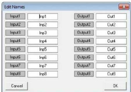
Fig. 33 Window "Edit Names"
6.13 Managing configurations
The configurations created by means of the control program may be permanently saved as "programs" on six storage locations of the DRM-882LAN. These configurations can be retrieved by means of the six buttons PRESET (3) at the unit. Four additional configurations may be saved as "extra programs" on the unit. These configurations can be retrieved via switching signals at the inputs INPUT PORT (13) ( chapter 6.15).
All configurations may be additionally saved on the computer.
6.13.1 Saving configurations on the computer
To save the current configuration on the computer:
1) On the upper right of the configuration window, click the button "Save". The dialog window "Save As" is displayed.
2) Enter the file name desired, select the location where the file is to be saved and then save the file.
By default, the subfolder "Preset" is selected which was automatically created during program installation. The file extension *.M88 is automatically appended to the file name entered.
6.13.2 Loading configurations from the computer
CAUTION

Prior to loading a configuration, check if it corresponds to the units connected.
As the DRM-882LAN provides flexible configuration options, the inputs and outputs may assume most diverse functions. An inadvertent change between configurations may result in an overload of the components connected.
To load a configuration that has been saved on the computer:
1) On the upper right of the window, click the button "Load". The dialog window "Open" is displayed.
2) Select the file desired and confirm your selection.
6.13.3 Saving configurations on the unit
To save the current configuration on the DRM-882LAN:
1) On the upper right of the window, click the button "Store". The dialog window "Store Program" is displayed (fig. 34).
![Store program Memory Program 01: 1.516 Stereo Out 02: 2.516 Stereo MID 03: 3.516 Stereo CUT 04: 4.516 StereoLOUD 05: Program default 06: Program default Edit Name [max size 16 characters] 1.516 Stereo Out Select position 1 Cancel Store](/content/2026/06/1400817/images/680a116a91bb574e9d1869ea5d3900203ec9e2cc7d94f45893670363ebe2aa7a.jpg)
Fig. 34 Window "Store Program"
2) To select the storage location, use the field "Select Position" or click an entry in the list under "Memory Program". Select a free storage location ("Program Empty") or select a storage location already assigned that you want to overwrite.
3) In the field "Edit Name", enter the name for the configuration. The length of the name may not exceed 16 characters. Special (language-specific) characters (e.g. ä, ö, ü, β, è, ô, i, á, ñ, μ) should not be used, as they will not appear correctly on the display of the DRM-882LAN.
4) Click the button "Store" to save the configuration or click "Cancel" to cancel the procedure.
5) In the dialog window "Store Program – Are you sure?", confirm or cancel the procedure.
After the saving procedure has been completed, the window "Store Program" disappears.
The configurations that have been saved in the unit by means of this procedure can be directly retrieved via the buttons PRESET 1–6 (3) after the connection to the computer has been disconnected.
6.13.4 Loading configurations from the unit
To retrieve a configuration saved on the DRM-882LAN and to load it onto the computer:
1) On the upper right of the window, click the button "Read". The dialog window "Read Program" is displayed (fig. 35).

Fig. 35 Window "Read Program"
2) Select a configuration from the list under "Memory Program".
3) Click the button "Read" to load the configuration selected or click "Cancel" to cancel the procedure.
If a free storage location ("Program Empty") is selected, an error message will appear.
4) In the dialog window "Read Program – Overwrite current editing, are you sure?", confirm or cancel the procedure.
After the loading procedure has been completed, the window "Read Program" disappears.
6.13.5 Extra configurations
Four additional configurations ("extra configurations") may be saved on the DRM-882LAN. They can be retrieved via switching signals at the inputs INPUT PORT (13) (Chapter 6.15).
The procedures for saving the extra configurations on the unit and loading them from the unit are identical to those described in the two previous chapters; however, the buttons "Store" and "Read" in the section "Extra Program" are used.
6.14 Switching outputs
To set the switching outputs, click the button "Switch" located on the upper right of the configuration window. The dialog window "Switch" (fig. 36) is displayed. The upper section of this dialog window indicates the switching status of the four switching outputs. A tick in the box next to the name of a switching output indicates that the switching output is activated. To change the switching status, click the corresponding box.
The second section of the dialog window provides the buttons 1 – 10 that allow the user to switch between the ten savable switch presets. A tick in the box next to "Link Switch preset to Audio preset" will link the switching combination saved on the unit with the corresponding unit configuration (program). If, for example, a configuration is retrieved by button PRESET 3, the unit will automatically switch to switching combination 3.
The switching combinations 7 to 10 are linked to the extra configurations 1 to 4 ( chapter 6.13.5), i. e. they are retrieved via the switching inputs INPUT PORT (13).

Fig. 36 Window "Switch"
6.14.1 Renaming switching outputs
The names of the switching outputs are factory-set to "S1" to "S4". These names may be changed, e. g. to indicate the function of the units controlled. To change the names of the switching outputs:
1) Click the button "Edit Switch Name". The dialog window "Edit Switch Name" is displayed (fig. 37).
2) Overwrite the names of the desired switching outputs in the corresponding input fields (max. 16 characters).
3) Click "Confirm" to confirm the procedure or click "Cancel" to cancel it.
The names entered will be saved on the computer.

Fig. 37 Window "Edit Switch Name"
6.14.2 Saving a switching combination on the unit
1) Use the buttons 1-10 to select the switching combination to be saved.
2) Under "Switch", click the boxes to switch on /off the switching outputs as desired.
3) Click the button "Store to device".
A message appears confirming that the switching combination has been saved on the selected storage location of the DRM-882LAN.
6.14.3 Saving a switching combination on the computer
1) Use the buttons 1-10 to select the switching combination to be saved.
2) Click the button "Save to PC". The dialog window "Save As" is displayed.
3) Enter the file name desired, select the location where the file is to be saved and then save the file.
By default, the subfolder "Preset" is selected which was automatically created during program installation. The file extension *.swc is automatically appended to the file name entered.
Note: Only the switching statuses are saved and not the number of the combination, i. e. the switching statuses saved can later be loaded into another switch preset.
6.14.4 Loading a switching combination from a computer
1) Use the buttons 1-10 to select the switching combination for which saved switching statuses are to be loaded from the computer.
2) Click the button "Load from PC". The dialog window "Open" is displayed.
3) Select the file desired and then confirm your selection.
The switching outputs will adopt the switching statuses saved in the file.
6.15 Switching inputs
The four extra configurations saved on the unit may be retrieved via external switching signals. In addition, different priorities can be assigned to the switching inputs.
1) To configure the switching inputs, click the button "Configure" located on the right-hand side of the window (under "Extra Program"). The dialog window "Configure External Signal" (fig. 38) is displayed.
2) After the settings described in chapters 6.15.1 to 6.15.3 have been made, click the button "Confirm" to confirm your changes.
3) In the dialog window "Configure – Are you sure?", confirm or cancel the procedure.

Fig. 38 Window "Configure External Signal"
6.15.1 Enabling or disabling inputs
Under "External Signal Enable", select the switching signals at the connections INPUT PORT (13) that are to be enabled for switching over the configuration. A tick in the box indicates that the corresponding input will be included in the switchover procedure.
6.15.2 Selecting the logic type (high/low)
Under "Active Mode", define if the switch-over is to be triggered by high level ["External Input line active High" (+5 V)] or low level ["External Input line active Low" (0 V)].
6.15.3 Selecting priorities
Under "Priority", select the priority to be used for the switching inputs during switchover. Click the button "?" to call up a table (fig. 39) providing information on the actual meaning of the number entered in the field "Configure Priority". For each number, the table lists, in descending order, the priorities that are assigned to the individual inputs.
Example:
All inputs have been enabled for switchover. The logic type is "active High" and the value in the field "Configure Priority" has been set to 3, i.e., according to the table, the order of the inputs is S1, S4, S3, S2. This means:
If switching input 1 is on high level (+5 V are present between terminal "S1" and the 1 extra configuration will be retrieved (consequently, the other inputs will be of no relevance).
If switching input 1 is on low level (0 V are present between terminal "S1" and λ and if switching input 4 is on high level, the 4th extra configuration will be retrieved.
If the switching inputs 1 and 4 are on low level and if switching input 3 is on high level, the 3rd extra configuration will be retrieved.
If switching inputs 1, 3 and 4 are on low level and if switching input 2 is on high level, the 2nd extra configuration will be retrieved.
| Priority | With mode = Signal Active High | With mode = Signal Active Low |
| 0 | recall program E4 if S4 = 1 or recall program E3 if S3 = 1 or recall program E2 if S2 = 1 or recall program E1 if S1 = 1 | recall program E4 if S4 = 0 or recall program E3 if S3 = 0 or recall program E2 if S2 = 0 or recall program E1 if S1 = 0 |
| 1 | recall program E3 if S3 = 1 or recall program E2 if S2 = 1 or recall program E1 if S1 = 1 or recall program E4 if S4 = 1 | recall program E3 if S3 = 0 or recall program E2 if S2 = 0 or recall program E1 if S1 = 0 or recall program E4 if S4 = 0 |
| 2 | recall program E2 if S2 = 1 or recall program E1 if S1 = 1 or recall program E4 if S4 = 1 or recall program E3 if S3 = 1 | recall program E2 if S2 = 0 or recall program E1 if S1 = 0 or recall program E4 if S4 = 0 or recall program E3 if S3 = 0 |
| 3 | recall program E1 if S1 = 1 or recall program E4 if S4 = 1 or recall program E3 if S3 = 1 or recall program E2 if S2 = 1 | recall program E1 if S1 = 0 or recall program E4 if S4 = 0 or recall program E3 if S3 = 0 or recall program E2 if S2 = 0 |
| 4 | recall program E1 if S1 = 1 or recall program E4 if S4 = 1 or recall program E3 if S3 = 1 or recall program E2 if S2 = 1 | recall program E1 if S1 = 0 or recall program E4 if S4 = 0 or recall program E3 if S3 = 0 or recall program E2 if S2 = 0 |
| 5 | recall program E2 if S2 = 1 or recall program E3 if S3 = 1 or recall program E4 if S4 = 1 or recall program E1 if S1 = 1 | recall program E2 if S2 = 0 or recall program E3 if S3 = 0 or recall program E4 if S4 = 0 or recall program E1 if S1 = 0 |
| 6 | recall program E3 if S3 = 1 or recall program E4 if S4 = 1 or recall program E1 if S1 = 1 or recall program E2 if S2 = 1 | recall program E3 if S3 = 0 or recall program E4 if S4 = 0 or recall program E1 if S1 = 0 or recall program E2 if S2 = 0 |
| 7 | recall program E4 if S4 = 1 or recall program E1 if S1 = 1 or recall program E2 if S2 = 1 or recall program E3 if S3 = 1 | recall program E4 if S4 = 0 or recall program E1 if S1 = 0 or recall program E2 if S2 = 0 or recall program E3 if S3 = 0 |
Fig. 39 Window "Priority Info"
6.16 Selecting the interface mode
Similar to the procedure in the system menu, it is possible to define if one of the interfaces USB or RS-485 is to be set manually or to be recognized automatically by the unit.
1) In the configuration window, under "USB/ RS 485", click the button "Setup". The dialog window "USB/ RS 485 Setup" is displayed.
2) From the list field, define if the switchover is to be performed automatically ("USB/RS 485 Automatic") or if the USB or RS-485 interface most recently set by means of the system menu (Chapter 5.3.3) is to be used ("USB/RS 485 Manual").
3) Click "OK" to confirm your selection or click "Cancel" to cancel it.
6.17 Locking the unit
To protect the unit against unauthorized operation, click the button "Lock Front-panel" on the upper right of the display so that it appears to be "pressed". Once the connection to the computer has been disconnected (configuration window closed [13 chapter 6.18] and "Disconnect" clicked), it will not be possible to operate the DRM-882LAN via its buttons
To unlock, re-establish the connection to the computer ("Connect"), call up the configuration window ("Edit") and press ("disengage") the button "Lock Front-panel".
6.18 Exiting a configuration window
To exit a configuration window, click the button ☒ located in the upper right corner. Then confirm the confirmation message.
7 Specifications
DRM-882LAN
Frequency range: .....20–20 000 Hz ±1 dB
Audio inputs
Input voltage: .....6.2 V (max.)
Impedance: .....10kΩ
Connections: ....Screw terminals, balanced
Phantom
power supply: .....+48V, switchable
Audio outputs
Output voltage: .....6.2V (max.)
Impedance: .....50Ω
Connections: ....Screw terminals, balanced
S/N ratio (A-weighted)
Microphone: .....> 98 dB
Line: ....> 104 dB
THD: ....< 0.005 %
A/D and D/A converters
Quantization: .....24 bit
Sampling rate: .....48 kHz
Signal processor
DSP type:.....SAM3716
Data format: .....24 bit (data) × 96 bit (coefficients)
Switching inputs: .....0-5V (TTL level)
Switching outputs: . . . .0–5V (TTL level), 150mA (max.)
Power supply: ..... 230V/50Hz
Power consumption: . . .20 VA (max.)
Ambient temperature: .0–40°C
Dimensions
Width: 482 mm
Height: 44 mm, 1 RS (rack space)
Depth: 250 mm
Weight: 2.5 kg
DRM-882WP
Dimensions (W × H): . . .86 × 86 mm
Mounting depth: ....30 mm
Power supply:....=5V/20mA
DRM-882WPX
Dimensions (W × H): ...144 × 80 mm
Mounting depth: . . . .45 mm
Power supply:....=12 V/75 mA
Subject to technical modification.
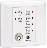
- 6.4.7 KLANGEINSTELLUNG
- CONTENT
- 1 OVERVIEW
- 1.1 FRONT PANEL
- 1.2 REAR PANEL
- 1.3 CONTROL PANEL DRM-882WP
- 1.4 CONTROL PANEL DRM-882WPX
- 2 SAFETY NOTES
- 3 APPLICATIONS
- 3.1 CONTROL PANELS
- MASTER MODE
- ZONE MODE
- 4 SETTING UP AND CONNECTING THE UNIT
- 4.1 SIGNAL SOURCES
- 4.2 AMPLIFIERS OR OTHER UNITS
- 4.3 EXTERNAL SWITCHING SIGNALS
- 4.4 UNITS TO BE CONTROLLED
- 4.5 CONTROL PANEL DRM-882WP
- 4.5.1 SETTING UP THE CONTROL PANEL
- 4.6 CONTROL PANEL DRM-882WPX
- 4.6.1 SETTING UP THE CONTROL PANEL
- 4.7 COMPUTER
- 4.8 MAINS CONNECTION
- 5 OPERATION
- 5.1 SWITCHINGON/OFF
- 5.2 SELECTING A CONFIGURATION
- 5.3 SYSTEM SETTINGS
- 5.3.1 SETTING THE IP ADDRESS
- 5.3.2 DHCP
- 5.3.3 SELECTING AN INTERFACE
- 5.3.4 UNIT NUMBER FOR RS-485
- 5.3.5 RETRIEVING SWITCHING COMBINATIONS
- 5.3.6 LINKING SWITCHING COMBINATIONS TO CONFIGURATIONS
- 5.4 STATUS LEDS
- 5.5 OPERATION VIA DRM-882WP
- 5.6 OPERATION VIA DRM-882WPX
- 5.6.1 OPERATING MODE "MASTER
- 5.6.2 OPERATING MODE "ZONE
- 5.6.3 STANDBY MODE
- 6 REMOTE CONTROL VIA A COMPUTER
- 6.1 INSTALLING PC SOFTWARE
- 6.1.1 INSTALLING AN INTERFACE DRIVER
- 6.2 STARTING THE PC SOFTWARE
- 6.2.1 ADDING UNITS
- 6.2.2 SEARCHING THE NETWORK FOR UNITS
- 6.2.3 CONNECTING OR DISCONNECTING UNITS
- 6.2.4 NAMING A UNIT
- 6.2.5 CALLING UP THE CONFIGURATION WINDOW
- 6.2.6 REMOVING UNITS
- 6.2.7 SAVING A UNIT CONSTELLATION
- 6.2.8 LOADING A UNIT CONSTELLATION
- 6.2.9 CHANGING THE INTERFACE
- 6.2.10 SETTING THE ID NUMBER OR THE IP ADDRESS
- 6.2.11 EXITING THE PROGRAM
- 6.3 VIEWS
- 6.3.1 UNIT FOR SIGNAL DELAY
- 6.4 CONFIGURING INPUTS
- 6.4.1 SELECTING THE SIGNAL LEVEL
- 6.4.2 SELECTING THE SIGNAL TRANSMISSION TYPE
- 6.4.3 PHANTOM POWER SUPPLY
- CAUTION
- 6.4.4 LINKING INPUTS AS A STEREO PAIR
- 6.4.5 GAIN
- 6.4.5.1 MAIN CONTROL "MASTER INPUT GAIN
- 6.4.6 NOISE GATE
- 6.4.7 SOUND ADJUSTMENT
- 6.4.7.1 FREQUENCY RESPONSE
- 6.4.8 FEEDBACK SUPPRESSION (FBK)
- 6.4.9 PHASE REVERSAL
- 6.5 CONFIGURING OUTPUTS
- 6.5.1 ASSIGNING/MIXING INPUTSIGNALS
- 6.5.2 SIGNAL DELAY
- 6.5.3 HIGH PASS FILTER AND LOW PASS FILTER
- 6.5.4 EQUALIZATION
- 6.5.4.1 FREQUENCY RESPONSE
- 6.5.5 COMPRESSOR
- 6.5.6 GAIN
- 6.5.7 LIMITER
- 6.5.8 PHASE REVERSAL
- 6.5.9 MAIN CONTROL
- 6.6 AUTOMIXER
- 6.7 DUCKER
- 6.8 STATUS DISPLAY
- 6.9 MUTING
- 6.10 LINKING CHANNELS
- TO LINK INPUT CHANNELS
- TO LINK OUTPUT CHANNELS
- 6.11 COPYING ADJUSTMENTS
- 6.11.1 COPYING ADJUSTMENTS OF AN INPUT
- 6.11.2 COPYING ADJUSTMENTS OF AN OUTPUT
- 6.12 RENAMING INPUTS AND OUTPUTS
- 6.13 MANAGING CONFIGURATIONS
- 6.13.1 SAVING CONFIGURATIONS ON THE COMPUTER
- 6.13.2 LOADING CONFIGURATIONS FROM THE COMPUTER
- 6.13.3 SAVING CONFIGURATIONS ON THE UNIT
- 6.13.4 LOADING CONFIGURATIONS FROM THE UNIT
- 6.13.5 EXTRA CONFIGURATIONS
- 6.14 SWITCHING OUTPUTS
- 6.14.1 RENAMING SWITCHING OUTPUTS
- 6.14.2 SAVING A SWITCHING COMBINATION ON THE UNIT
- 6.14.3 SAVING A SWITCHING COMBINATION ON THE COMPUTER
- 6.14.4 LOADING A SWITCHING COMBINATION FROM A COMPUTER
- 6.15 SWITCHING INPUTS
- 6.15.1 ENABLING OR DISABLING INPUTS
- 6.15.2 SELECTING THE LOGIC TYPE (HIGH/LOW)
- 6.15.3 SELECTING PRIORITIES
- EXAMPLE
- 6.16 SELECTING THE INTERFACE MODE
- 6.17 LOCKING THE UNIT
- 6.18 EXITING A CONFIGURATION WINDOW
- 7 SPECIFICATIONS
- DRM-882LAN
- DRM-882WP
- DRM-882WPX
Brand : Monacor
Model : DRM-882WPX
Category : Remote control