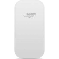
WL-CPE5G24D-080 - Network switch Mach Power - Free user manual and instructions
Find the device manual for free WL-CPE5G24D-080 Mach Power in PDF.


| Product Type | Wireless Access Point / Router |
| Model | WL-CPE5G24D-080 |
| Brand | Mach Power |
| Dimensions (W x D x H) | 200 x 150 x 30 mm |
| Weight | 300 g |
| Power Supply | DC 12V, 1A |
| Wireless Standard | IEEE 802.11a/b/g/n/ac (dual-band) |
| Frequency Bands | 2.4 GHz and 5 GHz |
| Max Data Rate | Up to 1200 Mbps (2.4 GHz: 300 Mbps, 5 GHz: 867 Mbps) |
| Ethernet Ports | 1 x Gigabit WAN, 4 x Gigabit LAN |
| Antenna Type | External dual-band antennas (2x) |
| Security Protocols | WPA/WPA2-PSK, WPA3 |
| Management | Web-based GUI, Mobile App |
| Maintenance | Restart monthly; keep firmware updated |
| Cleaning | Wipe with dry cloth; avoid liquids |
| Safety | Use in dry, ventilated area; avoid heat sources |
| Spare Parts | Contact Mach Power support or authorized dealers |
| Repairability | Not user-serviceable; consult professional technician |
| General Information | Designed for home and small office networks |
Frequently Asked Questions - WL-CPE5G24D-080 Mach Power
User questions about WL-CPE5G24D-080 Mach Power
0 question about this device. Answer the ones you know or ask your own.
Ask a new question about this device
Download the instructions for your Network switch in PDF format for free! Find your manual WL-CPE5G24D-080 - Mach Power and take your electronic device back in hand. On this page are published all the documents necessary for the use of your device. WL-CPE5G24D-080 by Mach Power.
USER MANUAL WL-CPE5G24D-080 Mach Power
User manual
CPE DIP SWITCH POE 24V
WL-CPE2G24D-075 / WL-CPE5G24D-076 / WL-CPE5G24D-080
INDEX
1 Connection Diagram ... 4
1.1 Connection diagram between POE with the CPE ... 4
2. DIP Device instruction ... 4
3. Setting the signal strength ... 6
4. Questions & answers ... 7
5. DIP codes, segment and frequency ... 9
1. CONNECTION DIAGRAM
1.1 Connection diagram between POE with the CPE


POE port: connect the LAN1 or LAN2 port to the AP.
LAN POE: connect to PC, camera, Switch or XVR.
Notes
- Both RJ45 ports (black and yellow) on the AP are LAN connections.
- If you want to enter the web page, you have to manually enter the IP address of the PC.
- The POE adapter has 3 inputs. One for the power cable, 2 for connectivity.
- The POE adapter is not intended for outdoor use. It is advisable to keep it away from atmospheric phenomena.
At the bottom of the device there are 2 RJ45 inputs, one called POE and the other LAN.
Use a Cat5 cable to connect the device to the PC, camera, Switch or XVR.
2. DIP DEVICE INSTRUCTION

Key 1: changes the device mode, UP is the AP (Access Point) mode to be used for PC, Switch or XVR, DOWN to be used for cameras.
Keys 2 to 8: these are for the coupling of different AP devices. There are 128 different combinations that can be created using the 7 Matching keys, which correspond to 128 different SSIDs and 128 different segments. Pages 8 to 15 below show all possible combinations.
Keys 9 & 10: There are for point to multipoint functionality. It is possible to use up to 4 cameras with one dvr. Configure the DIP switches as follows:
-
From dvr / PC / switch, switches 9 and 10 should remain up.
-
From the camera, select one of the 4 configurations for switches 9 and 10:
Camera 1: 9 lowered and 10 lowered
Camera 2: 9 lowered and 10 raised
Camera 3: 9 raised and 10 lowered
Camera 4: 9 raised and 10 raised
- Switch settings between cameras cannot be duplicated for buttons 9 and 10 or interference may be caused, up to 4 points.
Remarks:
-
Restart the AP after finishing the DIP settings.
-
The default SSID of the AP type DIP is not transmitted, the password has been set and can be customized.
-
Make sure the IP address of the camera is different from that of the AP Point to Multipoint, as following picture:

flowchart
graph TD
    A["NVR"] --> B["Up: Working mode key"]
    B --> C["Matching key"]
    C --> D["Default"]
    B --> E["Transmitter"]
    E --> F["Receiver"]
    F --> G["1 Down"]
    F --> H["2 Down"]
    F --> I["3 Down"]
    F --> J["4 Down"]
    F --> K["5 Down"]
    F --> L["6 Down"]
    F --> M["7 Down"]
    F --> N["8 Down"]
    F --> O["9 Down"]
    F --> P["10 Down"]
    F --> Q["11 Down"]
    F --> R["12 Down"]
    F --> S["13 Down"]
    F --> T["14 Down"]
    F --> U["15 Down"]
    F --> V["16 Down"]
    F --> W["17 Down"]
    F --> X["18 Down"]
    F --> Y["19 Down"]
    F --> Z["20 Down"]
    F --> AA["21 Down"]
    F --> AB["22 Down"]
    F --> AC["23 Down"]
    F --> AD["24 Down"]
    F --> AE["25 Down"]
    F --> AF["26 Down"]
    F --> AG["27 Down"]
    F --> AH["28 Down"]
    F --> AI["29 Down"]
    F --> AJ["30 Down"]
    F --> AK["31 Down"]
    F --> AL["32 Down"]
    F --> AM["33 Down"]
    F --> AN["34 Down"]
    F --> AO["35 Down"]
    F --> AP["36 Down"]
    F --> AQ["37 Down"]
    F --> AR["38 Down"]
    F --> AS["39 Down"]
    F --> AT["40 Down"]
    F --> AU["41 Down"]
    F --> AV["42 Down"]
    F --> AW["43 Down"]
    F --> AX["44 Down"]
    F --> AY["45 Down"]
    F --> AZ["46 Down"]
    F --> BA["47 Down"]
    F --> BB["48 Down"]
    F --> BC["49 Down"]
    F --> BD["50 Down"]
    F --> BE["51 Down"]
    F --> BF["52 Down"]
    F --> BG["53 Down"]
    F --> BH["54 Down"]
    F --> BI["55 Down"]
    F --> BJ["56 Down"]
    F --> BK["57 Down"]
    F --> BL["58 Down"]
    F --> BM["59 Down"]
    F --> BN["60 Down"]
    F --> BO["61 Down"]
    F --> BP["62 Down"]
    F --> BQ["63 Down"]
    F --> BR["64 Down"]
    F --> BS["65 Down"]
    F --> BT["66 Down"]
    F --> BU["67 Down"]
    F --> BV["68 Down"]
    F --> BW["69 Down"]
    F --> BX["70 Down"]
    F --> BY["71 Down"]
    F --> BZ["72 Down"]
    F --> CA["73 Down"]
    F --> CB["74 Down"]
    F --> CC["75 Down"]
    F --> CD["76 Down"]
    F --> CE["77 Down"]
    F --> CF["78 Down"]
    F --> CG["79 Down"]
    F --> CH["80 Down"]
Note: For a single point-to-point case, it doesn't matter which slot you use. Just make sure that the Working mode key and Matching key are set correctly.
3. SETTING THE SIGNAL STRENGTH
If you want to change the settings of the AP. Follow the following settings.
- Assign a static IP address to the PC in the same range as the AP:

Note: The subnet mask must be "255.255.0.0" for IP "172.18.128.1".
Note: Ip address for 2.4G devices is 172.17.0.2 Subnet Mask is 255.255.0.0
Ip address for 5.8G devices is 172.18.0.2 Subnet Mask is 255.255.0.0
Enter the IP address of the corresponding AP device in the IE browser to enter the WEB page, the default password is "password". The signal strength can be set after login.

Transmit Power Configuration: Default is the maximum value, the transmit power should be reduced appropriately when the signal is too strong.
Encryption Configuration: Custom key can be used for security. (The same key must be set in the transmitter and receiver.)
Distance configuration: the default is two kilometers, it should be set according to your needs. (The same distance value must be set in the transmitter and receiver. Otherwise, a low-latency, low-bandwidth network connection will occur.)
4. QUESTIONS & ANSWERS
Q1: What should be noted when setting the AP DIP switches?
A1: Make sure the power is off
Q2: How does the AP work without a dedicated power supply?
A2: The AP receives power through the cat5e cable. Called PoE. Two cables are required for connection. It is recommended to use STP Cat5e cables.
Q3: How long can the PoE cable be?
A3: The length of the cable depends on the supply voltage and the quality of the cable. For 24 V power supply, the cable length can typically be 100 meters and up to 200 meters for 48 V power supply.
Q4: Why don't I see any signal lights when the AP should be on?
A4: We recommend that you run a troubleshooting test as described below. For the transmitter, set all buttons "1" to "10" UP. For the receiver, set buttons "1" DOWN and buttons 2 to 10 UP. At the end turn on the device and wait 3 minutes. The distance between the transmitter and the receiver must be more than 2 meters. If you still see no indication that the units are on and communicating with each other, contact your dealer.

Transmitter Receiver

Q5: Why is the local network connection unstable after installation?
A5: We suggest you try two actions:
-
Change the cable to see if it is cable problem
-
Try changing the wireless channel (different DIP switch settings between buttons 2 and 8) to eliminate interference. If you are still having problems contact your dealer.
Q6: Is the 10-digit AP compatible with the previous 8-digit ones?
A6: Yes. Enter the WEP page, as per instructions, select the "system" menu, click on "mode", check the "8-digit DIP switch mode" box, then "Save changes". Turn off the AP, configure it according to the instructions for an 8-digit DIP device. (Focusing on buttons 1 to 8 only).
Q7: I have an 8-digit switch. Is it compatible with the new 10-digit devices?
A7: Yes. Enter the WEP page, as per instructions, select the "system" menu, click on "mode", check the "8-digit DIP switch mode" box, then "Save changes". Turn off the AP, configure it according to the instructions for an 8-digit DIP device. (Focusing on buttons 1 to 8 only).
Q8: After connecting the AP to the NVR, I am able to see the IP address of the camera, but no image.
A8: Try changing the LAN port of the AP. If you are still having problems contact your dealer.
Q9: What do the LEDs on the device represent?
A9: Red: PWR: Power LED: it is on when the device is connected to the power supply.
Blue: WLAN: Wifi signal LED. It is on when Wifi is active.
LAN1, LAN2, are on when the device is working.
Orange: wireless signal strength.
First LED lit: very weak signal.
First and second LEDs lit: weak signal.
First, second and third LEDs on: good signal.
All 4 LEDs lit: optimal signal.
If only the last (fourth) LED is lit, the signal is too strong. Try setting the signal strength as explained above.

Q10: How to reset the device?
A10: Press and hold the RST button for 6 seconds when the device is turned on.
Q11: Where to find the pairing code of the devices?
A11: Enter the device screen, click on System-Remote Management Settings. Check and enter the pairing code, save to complete the operation. For more information, follow the instructions in the Cloud manual.

5. 128 PAIR CODES, SEGMENT AND FREQUENCY CA BE REFERRED TO THE FOLLOWING CHARTH
5. 128 COPPIE DI CODICI, SEGMENTO E FREQUENZA POSSONO ESSERE RIFERITI AL SEGUENTE GRAFICO
flowchart
graph TD
    A["NVR"] --> B["Transmitter"]
    B --> C["Receptor"]
    subgraph Transmitter
        D["2.4G:AP 172.17.127.1\n5.8G:AP 172.18.127.1\n① Down ② ③"]
        E["2.4G:CPE 172.17.127.2\n5.8G:CPE 172.18.127.2\n① Down ② ③"]
        F["2.4G:CPE 172.17.127.3\n5.8G:CPE 172.18.127.3\n① Down ② ③"]
        G["2.4G:CPE 172.17.127.4\n5.8G:CPE 172.18.127.4\n① Down ② ③"]
        H["2.4G:CPE 172.17.127.5\n5.8G:CPE 172.18.127.5\n① Down ② ③"]
        I["Down ② ③"]
    end
    subgraph Receptor
        J["Camera1"]
        K["Camera2"]
        L["Camera3"]
        M["Camera4"]
    end
5. 128 PARES DE CÓDIGOS, SEGMENTO Y FRECUENCIA PUEDE REFERIRSE AL SIGUIENTE GRÁFICO
For any information and product updates
visit our website www.machpower.it
Mach Power® is a registered trademark
All rights reserved

- User manual
- CPE DIP SWITCH POE 24V
- INDEX
- CONNECTION DIAGRAM
- Connection diagram between POE with the CPE
- Notes
- DIP DEVICE INSTRUCTION
- Remarks:
- SETTING THE SIGNAL STRENGTH
- QUESTIONS & ANSWERS
- 128 PAIR CODES, SEGMENT AND FREQUENCY CA BE REFERRED TO THE FOLLOWING CHARTH
- 128 COPPIE DI CODICI, SEGMENTO E FREQUENZA POSSONO ESSERE RIFERITI AL SEGUENTE GRAFICO
- 128 PARES DE CÓDIGOS, SEGMENTO Y FRECUENCIA PUEDE REFERIRSE AL SIGUIENTE GRÁFICO
Brand : Mach Power
Model : WL-CPE5G24D-080
Category : Network switch