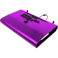
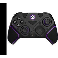
Pro FS - Controller PDP - Free user manual and instructions
Find the device manual for free Pro FS PDP in PDF.


| Product Type | Game Controller |
| Brand | PDP |
| Model | Pro FS |
| Dimensions (L x W x H) | 6.5 x 4 x 2 inches |
| Weight | 0.5 lbs |
| Power Source | Rechargeable lithium-ion battery or wired via USB |
| Battery Life | Up to 10 hours |
| Wireless Range | Up to 30 feet |
| Connection Type | USB-C wired or 2.4GHz wireless with included dongle |
| Compatibility | PC (Windows 10/11), Xbox One, Xbox Series X|S |
| Controls | Dual analog sticks, D-pad, A/B/X/Y buttons, triggers, bumpers |
| Additional Features | Headphone jack, vibration feedback, programmable back buttons |
| Cleaning | Use a soft, dry cloth. Do not use liquids or solvents. |
| Safety | Avoid exposure to extreme temperatures, moisture, and direct sunlight. |
| Spare Parts Available | Replacement thumbsticks, charging cable, and dongle |
| Repair Service | Refer to authorized PDP service center for repairs. |
| Warranty | 1 year limited warranty |
Frequently Asked Questions - Pro FS PDP
User questions about Pro FS PDP
0 question about this device. Answer the ones you know or ask your own.
Ask a new question about this device
Download the instructions for your Controller in PDF format for free! Find your manual Pro FS - PDP and take your electronic device back in hand. On this page are published all the documents necessary for the use of your device. Pro FS by PDP.
USER MANUAL Pro FS PDP
CONFIDENTIAL & PROPRIETARY: Information of Victrix may not be used, copied or disclosed without the prior written permission of Victrix, ©Victrix. All products are for presentation purposes only – final designs pending licensor approval.
VICTRIX™
Step 1: Disconnect Main Two Wire Harnesses
a) The larger wiring harness for the buttons has two locking tabs that push outward to release. The connector should then pull straight up.
b) The smaller wiring harness for the JLF should simply pull straight up and be disconnected.


VICTRIX™
Step 2: Removing the Back Cover
a) A series a 7 small/medium Philips head screws will need to be removed.
b) Once all screws are loosened/removed, the whole plastic cover can pull up to be removed (make sure the 2 locking tabs from the previous step have been closed/locked to allow the cover to come up)


VICTRIX™
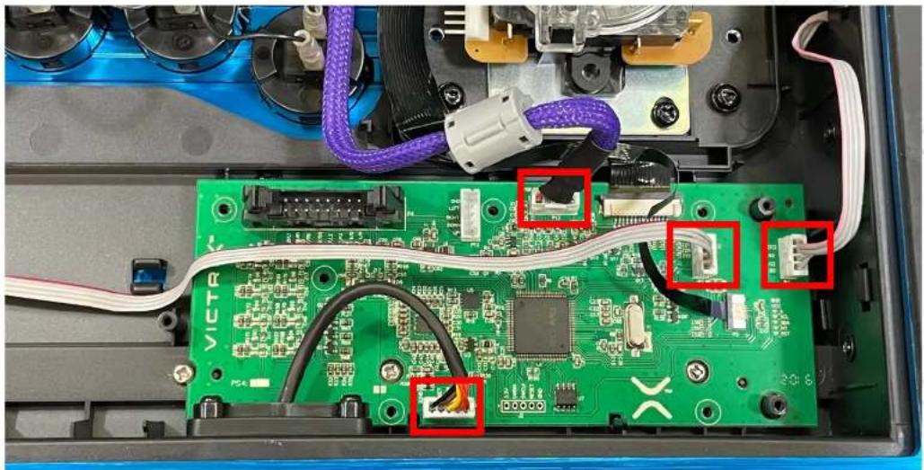
Step 3: Disconnect the 4 Wire Harnesses
a) After removing the back plastic cover, the main PCB will be exposed
b) Gently pull up and remove the connectors to the 4 wiring harnesses shown in the red rectangles. None of these having locking mechanisms and should pull straight up

VICTRIX™
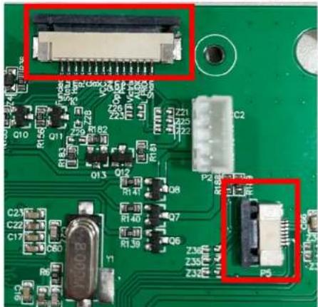
Step 4: Disconnect the 2 Ribbon Cables
a) The ribbon cables have a locking mechanism to keep them secured. If you look closely at the connector, you will see a black tab that needs to be pulled horizontally to release.
b) Once the tab is released, you can gently pull the ribbon cables horizontally along the PCB to disconnect

VICTRIX™
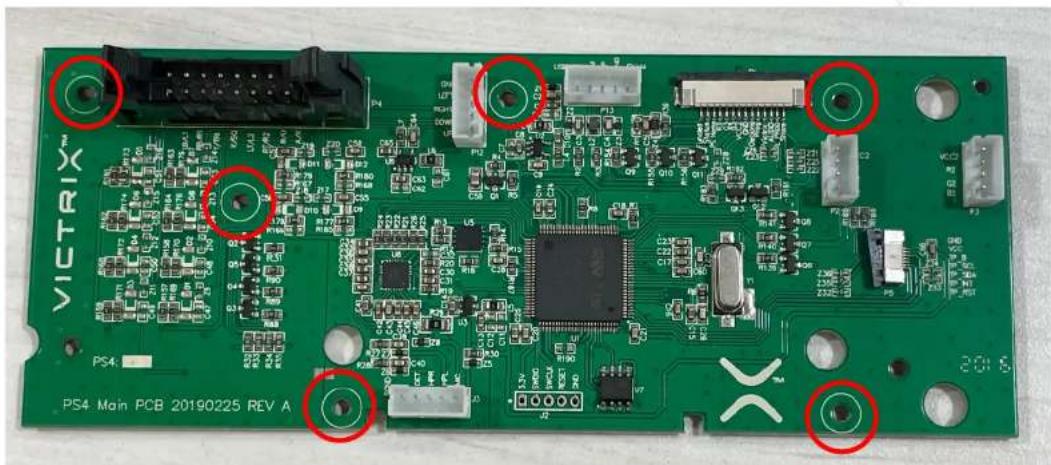
Step 5: Remove the Main PCB
a) After all cables and connectors have been disconnected, there are 6 screws securing the PCB.
b) Use a small Philips head screwdriver to remove the 6 screws circled in red.
VICTRIX™
Step 6: Reassemble
a) After the PCB has been removed, you can install the new PCB following the same steps in reverse order.
b) When connecting the 2 ribbon cables, make sure the locking tab is in the open position (shown in the Righthand picture in Step 4). Once the ribbon cable has been fully inserted, you will need to push the tab towards the connector itself to close/lock the tab.

Brand : PDP
Model : Pro FS
Category : Controller