
BRAE 181 - Air conditioner BEKO - Free user manual and instructions
Find the device manual for free BRAE 181 BEKO in PDF.
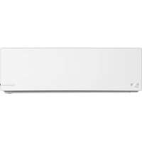


| Product Type | Portable Air Conditioner |
| Brand | Beko |
| Model | BRAE 181 |
| Cooling Capacity | 2.6 kW (9000 BTU/h) |
| Dimensions (W x D x H) | 45 x 35 x 70 cm |
| Net Weight | 28 kg |
| Power Supply | 220-240 V ~ 50 Hz |
| Power Consumption (Cooling) | 950 W |
| Energy Class | A |
| Noise Level (Max) | 64 dB(A) |
| Airflow | 300 m³/h |
| Condensate Water Tank | 1.5 L |
| Refrigerant | R290 (Propane) |
| Main Functions | Cooling, Dehumidification, Fan, Night Mode, 24h Timer |
| Controls | Digital Touch Panel and Remote Control |
| Air Filter | Washable Filter (every 15 days) |
| Maintenance and Cleaning | Clean the filter regularly, empty the water tank |
| Safety | Overheating protection, automatic shut-off if tipped over |
| Spare Parts | Filter, Remote Control, Exhaust Hose, Window Kit |
| Repairability | Parts available from Beko after-sales service |
Frequently Asked Questions - BRAE 181 BEKO
User questions about BRAE 181 BEKO
0 question about this device. Answer the ones you know or ask your own.
Ask a new question about this device
Download the instructions for your Air conditioner in PDF format for free! Find your manual BRAE 181 - BEKO and take your electronic device back in hand. On this page are published all the documents necessary for the use of your device. BRAE 181 by BEKO.
USER MANUAL BRAE 181 BEKO
BRAE 090/BRAE 091
BRAE 120/BRAE 121
BRAE 180/BRAE 181
BRAE 240/BRAE 241
BRAE 090 NG/BRAE 091 NG
BRAE 120 NG/BRAE 121 NG
BRAE 180 NG/BRAE 181 NG
BRAE 090_SKD/BRAE 091_SKD
BRAE 120_SKD/BRAE 121_SKD
BRAE 180_SKD/BRAE 181_SKD
BRAE 240_SKD/BRAE 241_SKD
EN
05M-8506243200-2222-02
CONTENTS
ENGLISH 3-46
V2203002
BRAE UM
Please read this user manual first!
Dear Customer,
Thank you for preferring a Beko product. We hope that you get the best results from your product which has been manufactured with high quality and state-of-the-art technology. Therefore, please read this entire user manual and all other accompanying documents carefully before using the product and keep it as a reference for future use. If you handover the product to someone else, give the user manual as well. Follow all warnings and information in the user manual.
Meanings of the symbols
Following symbols are used in the various section of this manual:

Important information or useful hints about usage.

Warning for hazardous situations with regard to life and property.

Warning to actions that must never perform.
Warning for electric shock.
This symbol shows that information is available such as the operating manual or installation manual.

Do not cover it.
This symbol shows that the operation manual should be read carefully.
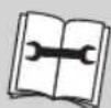
This symbol shows that a service personnel should be handling this equipment with reference to the installation manual.

This symbol indicates that this appliance uses a flammable refrigerant. If the refrigerant leaks and is exposed to an external ignition source, there is a risk of fire.

This product has been manufactured in modern facilities that respect the environment and do not harm nature.
CONTENTS
1 Safety instructions 6
1.1 Safety precautions 6 1.2 Symbol description....8 1.3 Installation instruction 8 1.4 Operating instruction 9 1.5 Operating instruction 13
2 Product introduction 16
2.1 Protect functions 16
3 Description of components 17
3.1 View of unit.... 17 3.2 Display screen 18 3.3 Indicator light 19 3.4 Remote controller....20 3.5 Remote controller display 22
4 Service and maintenance 24
4.1 Clean the front panel and remote controller....24 4.2 Clean air filter 24 4.3 No use for long time 25 4.4 Recommendations for energy saving 26
5 Troubleshooting 27
5.1 Air conditioner is in error 27 5.2 Remote controller is in error 27
CONTENTS
6 Normal phenomenons 28
7 Installation manual 29
7.1 Installation guide....29 7.2 Installation of accessories....29 7.3 Position for indoor unit 29 7.4 Position for outdoor unit 30 7.5 Tubing selection 30 7.6 Fixing installation panel 31 7.7 Indoor unit installation....32 7.8 Outdoor unit installation 33 7.9 Tubing connection 34 7.10 Connection of wires 34 7.11 Tube strapping 37 7.12 Exhaust 38 7.13 Drainage 40
8 European disposal guideline 41
9 Installation instructions 42
9.1 F-Gas instruction 42
10 Specifications 43
1 Safety instructions
1.1 Safety precautions

Warning:
Following these basic precautions will reduce the risk of fire, electrical shock, injury or death when using your air conditioner.
- Air conditioner must be connected to proper electrical outlet or breaker with the correct electrical supply. And only the specified power can be used.
- Proper grounding must be ensured to reduce the risk of shock and fire. DO NOT CUT OR REMOVE THE GROUNDING PRONG. If you do not have a three-prong electric receptacle outlet or breaker in the wall, have a certified electrician install the proper receptacle or breaker. The wall receptacle or breaker MUST be properly grounded.
- DO NOT use if power cord is frayed or otherwise damaged. Also avoid using it if there are cracks or abrasion damage along the length, plug or connector.
- DO NOT USE AN ADAPTER OR AN EXTENSION CORD.
- DO NOT block airflow inside or outside the air conditioner with blinds, drapes, protective covers, shrubs or bushes.
- Be careful of sharp edges on the front and rear fins of the unit that could cut and cause serious injury.
- Be careful when lifting the air conditioner to install or remove the unit. Always use two or more people for this.
- Always cut off the power of air conditioner before servicing it or moving it.
1 Safety instructions
- In some types of units, there is no appropriate plug corresponding to its power cord because of power. Under this condition, an appropriate power breaker should be linked to its power cord, therefore, the instruction part associated with plug using is not available for these types.
- An all-pole disconnection switch having a contact separation of at least 3mm in all poles should be connected in fixed wiring.
- The appliance shall be installed in accordance with national wiring regulations.
- This appliance is not intended for use by persons (including children) with reduced physical, sensory or mental capabilities, or lack of experience and knowledge, unless they have been given supervision or instruction concerning use of the appliance by a person responsible for their safety. Children should be supervised to ensure that they do not play with the appliance.
1 Safety instructions
1.2 Symbol description

Warning:
A symbol indicating operation which may cause personnel casualties or serious damages.
A symbol indicating operation which may cause personnel casualties or property damages.
1.3 Installation instruction

Warning:
Never install by yourself.
Split type air conditioner will work for you for a long period of time if it is correctly installed.
Improper installation could cause problems such as leakage of water or refrigerant, electric shock or fire.
If the power cable to the unit is disconnected, burnt, chipped, or detached from the terminal, to make reparations, please contact the nearest service center, or repaired by people who have the
same qualifications or experience to avoid electrical hazards.
Warning:
Please confirm the following before installation
Power specifications
Make sure that the capacity of socket or breaker and power cable is sufficient, the voltage is correct and the socket or breaker is grounded. There may be hazard of fire or electric shock otherwise.
Installation environments
Do not install air conditioner at the place where there is flammable or corrosive air.
• Proper connection of wires and piping
Improper connection may decrease the efficiency or cause the air conditioner to stop running. Water or refrigerant leakage may also result.
Operating instruction
Please operate the air conditioner in accordance with this manual.
1 Safety instructions
1.4 Operating instruction

Warning:
Following the safety messages is very important. These messages can save you from being injured or killed. Warning symbols alert you to be careful and mean danger. Always follow instructions to be safe and reduce the chances of injury or death. Warning and danger signs will precede safety messages.
Electrical safety

Warning:
Grounding: This room air conditioner must be grounded.
Grounding reduces the risk of electric shock by providing an escape wire for the electric current.
If the power cord has a grounding plug with a grounding wire, plug it into an outlet that is properly installed and grounded.
If the power cord does not have a grounding plug with a grounding wire, the grounding wire must connect to the breaker that is properly installed and grounded.
1 Safety instructions

Warning:
Improper use of the grounding plug or breaker can result in a risk of electric shock. Call a qualified electrician if you don't understand the grounding instructions or if you are not sure if the air conditioner is properly grounded. If the wall outlet or breaker is not grounded, please contact an electrician to have it replaced with a properly grounded outlet or breaker.
Do not, under any circumstances, cut or remove the third (ground) prong from the power cord.
Adapter plug: We strongly advise against using an adapter plug or breaker.
Operating conditions
- Temperature:
T1 instance: -7°C to 45°C (16°C to 45°C in cooling-only type)
T3 instance: -7°C to 52°C (16°C to 52°C in cooling-only type)
If the unit runs beyond the temperature for a long time, it may cause cooling capacity to decrease or protector to work.
- Relative humidity: <80%
If the unit runs beyond the humidity range, condensate may be formed near blade and outlet of air conditioner. It's normal.
- In heating operation, strange smell may come from the unit. It is normal phenomenon.
- The performance parameters refer to name plate.
1 Safety instructions
- The waterproof level of the indoor unit is IPX0. Do not use it in the laundry or bathroom.
- The outdoor unit cannot be installed in a closed area.
- Fuse: T3.15AL250V, rated current: 3.15A.
Tips
Install the unit on the north side, as normally that is the shaded side. This will enhance the operation of your unit. - Use correct electric voltage and proper ampere for the unit to run effectively. - Only let a certified electrician do any modifications to your electrical outlet or breaker. - Use a dedicated line for the operation of your air conditioner to avoid the possibility of an electrical surge. If the supply cord is damaged, it must be replaced by the
manufacturer or its service agent or a similarly qualified person in order to avoid a hazard.
The dimensions of the space necessary for correct installation of the appliance including the minimum permissible distances to adjacent structures.
The appliance shall be installed in accordance with national wiring regulations.
- Disconnect the power supply before cleaning and maintenance.
If the appliance is not connected by plug, an all-pole disconnection device which has at least 3mm separation distance in all pole and a residual current device (RCD) with the rating of above 10mA shall be incorporated in the fixed wiring according to the national rule.
1 Safety instructions
- If the appliance is connected by plug, it must be positioned so that the plug is accessible.
Energy Saving Guide
When installing your air conditioner make sure to seal all areas where there is a possibility of air leakage.
Airflow should not be blocked inside either by curtains, drapes or furniture or outside by shrubs or bushes.
- Do not needlessly use an electrical light or other appliances that produce heat.
- Keep the blinds and the drapes drawn on all the other window.
While cooking use an exhaust fan in the kitchen to remove the excess heat produced.
1 Safety instructions
1.5 Operating instruction
Only single-phase a.c. power can be used. Please refer to nameplate for details.
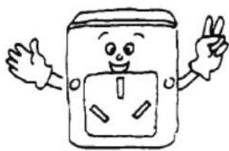
Do not put fingers or sticks into the inlet or outlet of air conditioner; the running fan may cause injuries.

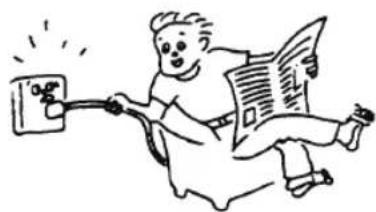
Do not switch on or off the unit by plugging or pulling off the plug, or by switching on or off the breaker.
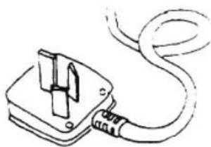
Use the specified power cord; do not change it.
Do not put anything on the outdoor unit.
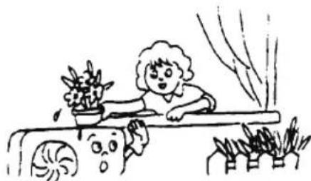
Keep indoor ventilated, especially when there is operating gas equipment.

1 Safety instructions
Do not substitute fuse with lead wire or other materials.
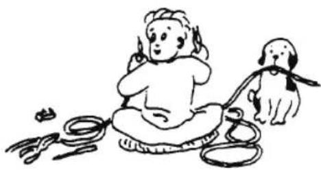
Pull off power plug or switch off breaker if the air conditioner is not used for a long time.

Safety Instruction

Warning:
The appliance is not intended for use by young children or infirm persons without supervision.
Young children should be supervised to ensure that they do not play with the appliance.
If the supply cord is damaged, it must be replaced by the manufacturer or its service agent or a similarly qualified person in order to avoid a hazard.
Do not connect the earth line to gas pipe or water pipe. Improper grounding may cause electric shock.

Do not pull off the power plug or switch off the breaker when it is in operation.

1 Safety instructions
Switch off the unit; cut off the power source and contact service agent if there is abnormal phenomenon (e.g. burning smell comes out).
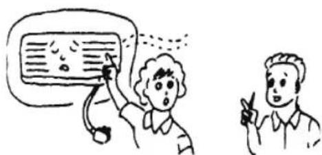
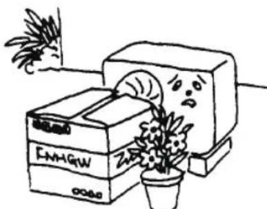
Do not place plants or animals directly in the path of the air conditioner's airflow. Doing so could harm them.

Switch off the unit, cut off the power source and make sure the fan stops before cleaning the unit.

Do not install air conditioner at the place where flammable gas may leak.
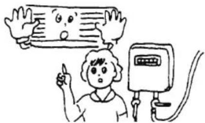
Please contact service agents for service. Improper service may cause accident.

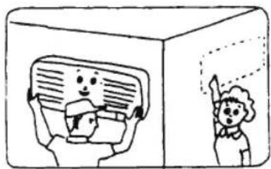
For removal and installation of air conditioner, please refer to professionals or contact service agents.
2 Product introduction
2.1 Protect functions
Protect functions can prolong the air conditioner's service life and provide more comfortable airflow.
- Delay-starting protection for the compressor
The compressor will restart working at least 3 minutes (5 minutes in heating mode) after being turned off to keep the pressure balance of the cooling system.

Note:
There will be 1 minute for the compressor to work after the unit is electrified for the first time.
- Freeze-prevention
To prevent indoor heat exchanger freezing in cooling and dehumidification operation, compressor or outdoor fan may stop running; indoor fan speed will be adjusted to a higher gear automatically.
• Dry for enzyme-prevention (optional)
Indoor fan motor will go on running for 3 minutes at low fan speed when turned off in cooling mode in order to keep dry condition inside the unit.
- Reset power or Auto restart (alternative)
Reset power: When there is a power suspension, air conditioner will automatically switch off. When the power is back, the unit will automatically reset power. For energy saving if there is no person in the room, air conditioner will stay in PAUSE status. User needs to turn on Air conditioner by remote controller.
Auto restart: The unit memories the operation mode, air flow setting, temperature setting etc., so that should there be a power failure when the unit is in operation, it will automatically return the same operating conditions when the power is restored.
• Cooling overload working (optional)
In cooling operation, if the temperature of outdoor heat exchanger is too high, indoor fan speed will be adjusted to a lower gear automatically and compressor may be stopped.
• Drip proof (optional)
In cooling and dehumidification operation, louver blades can change the position automatically to prevent dripping.
3 Description of components
3.1 View of unit

Note:
The air conditioner consists of an indoor unit, an outdoor unit, and a remote controller. The design and shape are different for different models. The above figures are only schematic, and they may be slightly different from the actual appliances you selected.
3 Description of components
3.2 Display screen

"RUN" indicator: This signal light is on when the unit is in "RUNNING" status. When in Defrosting or Cooling airflow proof, the indicator is flashing.
"TIMER" indicator: This signal light is on when the unit is in Timer.
"compressor" indicator: This signal light is on when the compressor is running (optional).

"Temperature" indicator: This display can show the set temperature. When the indicator displays F4, F1 or F2, it means the air conditioner runs abnormally.
(The above LED display is for reference only, subject to the actual product.)

Note:
- Flashing of any indicator means the air conditioner runs abnormally. Please contact the distributor in time.
- Function a: The air conditioner will only display the "RUN" indicator to save electricity if it does not receive any signal from the remote controller within 30 seconds. If it receives a signal from the remote controller for the second time, the display will still show the corresponding indicators. Function b: The indicators on the display screen can still be controlled by the "DISPLAY" button on the remote controller.

Note:
Function a or function b is optional, and it is designed before the product is dispatched from the factory.
3 Description of components
3.3 Indicator light
- "PAUSE" indicator This indicator lights red when the air conditioner is in defrosting or cooling airflow proof mode.
- "RUNNING" indicator This indicator lights green when the unit is in "RUNNING" status; the air conditioner is in HEAT, COOL, SWEEP, or DRY mode.
- "TIMER" indicator (Yellow) This indicator lights yellow when the unit is in TIMER mode.
- "AIR REFRESH" indicator (Green) (optional) This indicator lights green when the unit is in Air Refresh operation, and it will not light if the unit does not have the Air Refresh function.
- "RECEIVER" indicator This receiver receives signals from the remote controller.

Note:
If one of the "RUNNING", "PAUSE", or "TIMER" indicators flashes, please contact the distributor in time.
3 Description of components
3.4 Remote controller
3 Description of components
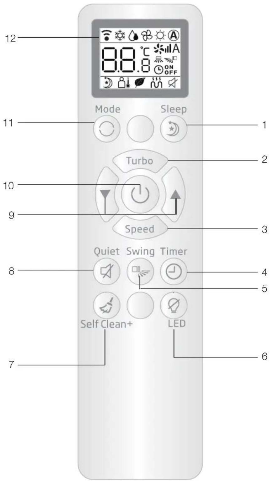
1. Sleep Button
For setting sleep function.
2. TURBO Button
To start or stop turbo function when air conditioner is in COOLING mode.
3. Fan speed button
For selecting indoor fan speed.

4. Timer selection Button
Press this button to select timer.
5. SWING Button
For changing vertical blades position and swing or not.
6. DISPLAY Button
To start or stop DISPLAY when air conditioner is in RUNNING.
7. CLEAN Button
Press this button to turn on "Self cleaning technology"
8. Quiet Button
Set the air conditioner to operate in low noise mode.
9. Temperature Adjustment Buttons
Press “▼” to decrease the temperature. Press “▲” to increase the temperature.
10. On/Off Button
Press this button to start or stop the air conditioner.
11. Mode Selection Button
For selecting the mode.


12. Display Screen
For setting the display.
Note:
- The HEAT ⚙ and AUTO Ⓐ functions and their displays are not available for cooling-only type air conditioners.
- If the user wants to cool or warm the room quickly, they can press the "turbo" button in cooling mode, and the air conditioner will run at maximum power. Pressing the "turbo" button again will exit the power function.
- The above illustration of the remote controller is for reference only; it may differ slightly from the actual product you have selected.
3 Description of components
3.5 Remote controller display

- Signal Emission Symbol
It appears when a control signal is emitted.
- Operating Mode Selection Display
Ⓐ AUTO
COOL
HEAT
DRY
FAN
- Turbo Display
It appears when the turbo function is set in COOLING mode, and the display
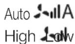
Wind Speed Selection Display
A
Auto speed
High speed
Medium speed
Low speed
- Vertical Swing Display
Displayed in accordance with vertical blades position and swing or not.
- Timer Display
Displayed when setting time to turn on or turn off the air conditioner.
- QUIET Display
Displayed when pressing QUIET button. (optional)
- Horizontal Swing Display
Displayed when pressing "H-SWEEP" button. (optional)
- AUH Display
The symbol appears when pressing "AUH" button in HEAT mode. (optional)
3 Description of components
9. UVC Display
It appears when UVC function is set. (optional)
10. I FEEL Display
It appears when I FEEL function is set. (optional)
11. Sleep Mode Display
Displayed when pressing "Sleep" button, the unit will run in sleep mode.
12. Setting temp Display
Displays the set temperature and timing time.
Instructions for remote controller
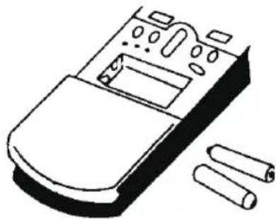
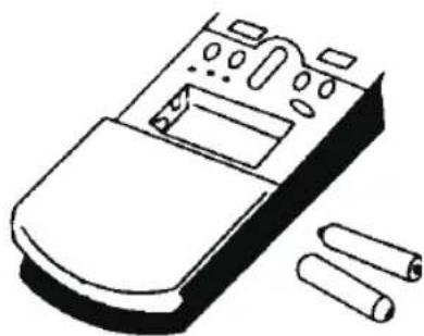
- The remote controller uses two AAA alkaline batteries under normal conditions; the batteries last for about 6 months. Please use two new batteries of similar type (pay attention to the poles when installing).
- When using the remote controller, point the signal emitter towards the indoor unit receiver; there should be no obstacle between the remote controller and the indoor unit.
- Pressing two buttons simultaneously will result in wrong operation.
- Do not use wireless equipment (such as a mobile phone) near the indoor unit. If interference occurs because of this, please switch off the unit, pull out the power plug, then plug it in again and switch it on after a while.
- Ensure there is no direct sunlight on the indoor receiver, or it may not receive the signal from the remote controller.
- Do not drop the remote controller.
- Do not place the remote controller in direct sunlight or near a heat source such as an oven.
- Do not spill water or juice on the remote controller. If this happens, clean it with a soft cloth.
- The batteries must be removed from the appliance before it is scrapped, and they must be disposed of safely.
4 Service and maintenance
Careful maintenance and regular servicing can prolong the life of the air conditioner and reduce electricity costs.


Warning:
- Stop the air conditioner using the remote controller and unplug it before performing any service or maintenance.
- Do not stand on unstable objects when cleaning or servicing the air conditioner, as this may cause personal injury.
- Do not touch the metal parts of the unit when removing the front panel, as this may cause personal injury.
4.1 Cleaning the front panel and remote controller
If the dirt can't be removed, please clean it with a warm damp cloth (soaked with warm water below 40°C).

Warning:
- Do not clean the unit with water, or it may cause electric shock.
- Do not clean the remote controller with water.
- Do not clean with alcohol, gasoline, banana oil, or polishing.
- Do not clean the unit violently, or it may cause the front panel to fall down.
- Do not clean the front panel or remote controller with a metal brush; it may damage the surface.
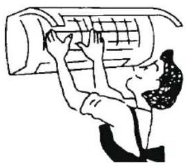
4.2 Clean air filter
- Open the front panel. (Fig. 4)
- Lift the protruding part, then pull it downward, and remove the air filter.
- Clean it with a vacuum cleaner or water. If the air filter is very dirty, please clean it with warm soapy water or mild detergent. Then dry it in the shade.
- Insert the air filter into its previous position, and close the front panel.
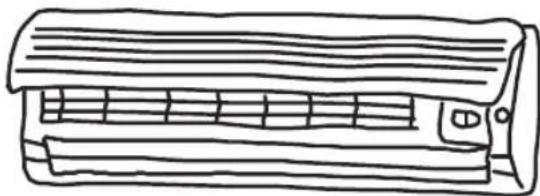
Fig. 4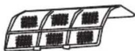
4 Service and maintenance

Note:
- Air filter should be cleaned at least once every two weeks, or heating or cooling capacity will be reduced.
- Do not clean the air filter with a metal brush; it may be damaged.
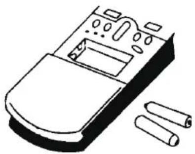
4.3 No use for long time
- Swing 3-4 hours to dry the internal air conditioner.
- Stop operation by remote controller, then cut off the power source of air conditioner.

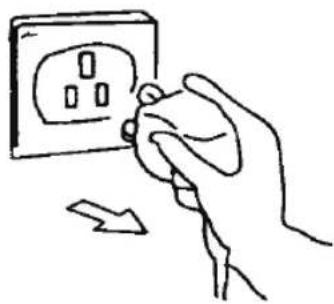
- Maintain air filter net. 4. Take out batteries from remote controller.
4 Service and maintenance
4.4 Recommendations for energy saving
Appropriate Temp Setting
It is harmful to health if the room is too cold.

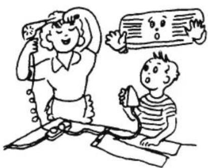
Avoid Heat Sources
When it is cooling, using other heat sources may affect cooling effect.
Keep Air Filter Clean
Keeping the air filter clean ensures high-efficiency operation.

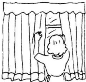
Avoid Direct Sunlight
When cooling, use a curtain or blind to obstruct direct sunlight.
Close Doors and Windows
Incoming outdoor air will affect the cooling or heating efficiency.

Good Ventilation
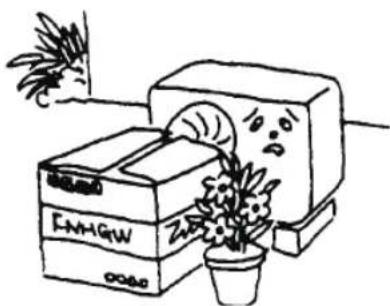
Do not place objects in front of the inlet and outlet of the outdoor unit.
5 Troubleshooting
5.1 Air conditioner is in error
Checking before service.
| Phenomenon Checking Items | |
| Air Conditioner Does Not Operate At All | 1. Check whether the power is disconnected. |
| 2. Check whether the breaker is switched on or the fuse is burnt. | |
| 3. Check the remote controller batteries. | |
| 4. Check whether radio equipment is used within 1m around the unit. | |
| Poor Cooling or Heating Performance | 1. Check whether the air inlet or outlet is blocked. |
| 2. Check whether dust is blocking the filter. | |
| 3. There may be too many people indoors. | |
| 4. Check whether doors or windows are closed. | |
| 5. Check whether fan speed or set temperature is improper. |
5.2 Remote controller is in error
The following "troubleshooting" is normal phenomenon
| Phenomenon Checking Items | |
| Fan stops or fan speed can not be controlled. | 1. When air conditioner is in DRY mode or SLEEP mode, fan speed can't be controlled sometimes. |
| 2. When air conditioner is in COOL AIRFLOW PROOF or DEFROSTING operation (in HEAT mode), fan motor will stop. | |
| 3. When air conditioner is in COOL or DRY mode, if air conditioner enters freeze-prevention operation, then fan speed can not be controlled. | |
| 4. When air conditioner is in HEAT mode, if air conditioner enters heating overload prevention operation, then fan speed can not be controlled. |
6 Normal phenomena
When heating or cooling, plastic parts may emit a sound due to temperature changes.
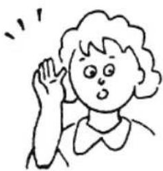
There may be a gentle "rustle" sound when the unit starts or stops. This is the normal sound of refrigerant flowing.
If the indoor humidity is too high, water drops may form on the front grill of the indoor unit. This is a normal phenomenon.

Walls, carpet, furniture, or clothes indoors may disseminate a peculiar smell.
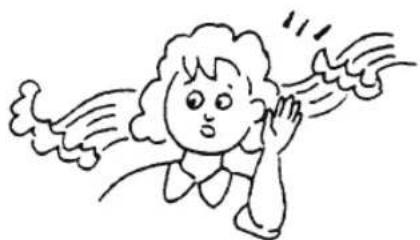
In order to protect the unit, when the compressor stops, there will be a 3-minute delay before restarting.
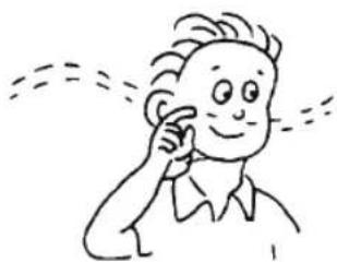
In the first several minutes of heating operation, wind may not come out from the indoor unit.
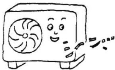
Water may flow out from the outdoor unit during heating operation.

In heating operation, steam may come out when it is defrosting.
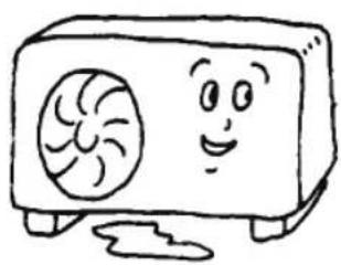

7 Installation manual
7.1 Installation guide
- This air conditioner meets the safety and operation standards promulgated by the Nation.
- You need to invite professional air conditioner service and maintenance personnel to install or remove the air conditioner. Problems may occur and you may suffer losses if non-professionals install the air conditioner.
- User shall provide the power that meets installation and operation requirements. Please refer to the nameplate for details about the voltage for this product. Voltage beyond this scope will affect the normal operation of the air conditioner.
- Separate power point with delay fuse protector or automatic breaker should be used for the air conditioner.
- The air conditioner must be correctly and reliably grounded, or it may cause electric shock or fire.
- Do not switch on the power of the air conditioner before well connecting and carefully checking the tubing and wires.
- The appliance shall not be installed in laundry or bathroom.
- In case necessary, please consult your supply authority for system information.
- The plug shall be accessible after installed the appliance.
- This instruction is subject to change without notice.
7.2 Installation of accessories
- Examine carefully the attached packing list and check whether the accessories are complete.
- Users may need to buy at their own expenses the articles not included in the packing list and may be needed in installing.
7.3 Position for indoor unit
- Away from the place where there is heat source, steam source, leakage of flammable gas and smoke.
- No obstacles near the inlet and outlet, and keep good ventilation. • Good discharge for water.
- At least 1m away from wireless equipment (such as TV, radio etc.).
- Mounted on the wall that can bear the weight of the air conditioner and won't produce noise while unit working.
- The distance between the indoor unit and the floor should be greater than 2.3m.
- The plug shall be accessible after installing the appliance.
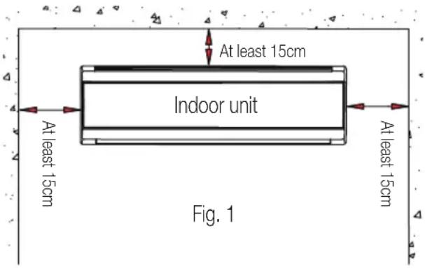
- Ensure the distance as required in Fig.1.
- The back of the indoor unit should be close to the wall (Fig.1)
- The figures are schematic only and may differ slightly from the actual appliances you selected.
7 Installation manual
7.4 Position for outdoor unit
- Avoid direct sunlight.
- Keep away from heat sources, steam sources, flammable gas leaks, smoke, and dust.
- Choose a location that is sheltered from rain (or snow) and well-ventilated.
- Ensure that neighbors are not affected by blown wind, noise, or discharged water. Also, choose a place that is easy to install and service.
- Mount the unit on a solid and reliable foundation to avoid increased noise or vibration.
- For optimal cooling performance, ensure that the front, rear, left, and right sides of the unit are in an open area.
- The outlet should be in open air; any obstacle will affect performance.
- The installation distance must comply with the requirements shown in Fig. 2.
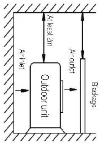
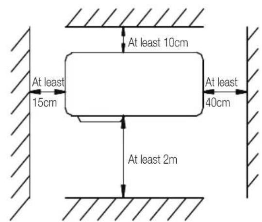
Fig. 2
7.5 Tubing selection
- Ensure that the level (height) difference of indoor and outdoor units and the length of tubing meet the requirement in Table 1.
- If the tubing is longer than 7m, but shorter than 15m, refrigerant should be supplemented according to Table 1.
- If the installation position of the outdoor unit is higher than indoor unit and the tubing is longer than 10m, add an oil trap on the gas tubing for every 8m. (Fig.3)
7 Installation manual

Fig. 3
| Tubing size (mm/inch) Standard tubing | Length (m) | Max tubing Length (m) | Height Difference (m) | Additional refrigerants (g/.m) | |
| Liquid tube Gas tube | |||||
| ∅ 6 (1/4") ∅ 9.52 (3/8") 5.0 9 5 12 | |||||
| ∅ 6 (1/4") ∅ 12 (1/2") 5.0 12 7 12 | |||||
| ∅ 6 (1/4") ∅ 15 .88 (5/8") 5.0 15 8 12 | |||||
| ∅ 9.52 (3/8") ∅ 15.88 (5/8") 5.0 15 8 15 | |||||
| ∅ 9.52 (3/8") ∅ 19.05 (3/4") 5.0 20 10 15 | |||||
The above dimensions are for reference only; the actual product shall prevail.
7.6 Fixing installation panel
- Dismantle the metal installation board of the indoor unit. Adjust the mounting panel to horizontal position.
- Drill holes and insert plastic expansion tubes at the appropriate locations on the wall and fix the installation board on the wall with M5 x 30 screws and washer 6. Ensure that there must be at least 4 fixed points in the wall. Ensure installation board to horizontal position.
- Drill holes as Fig. 4 shows. The hole, 80 mm in diameter, should slightly slide down outwards.
- Cut PVC tubes at a slight angle in the length shorter than wall thickness and insert it into the hole. (Fig. 5)
- Mount the wall cap.
7 Installation manual

7.7 Indoor unit installation
The tube may be connected in several directions as shown in the figures below.

Fig. 6
- Connecting right back tube (similar to right lower tube) (Optional, Refer to Fig.7)
- Pull out the tubing from the bottom of the chassis; and connect the drainpipe. Strap the joint of the tubing reliably.
- Lead the connecting wire to the indoor unit (Do not connect to the power).
- Strap together the tubes, discharge pipe, and connecting wire with adhesive tape. The discharge pipe is placed at the bottom.
- Remove the board which is on the chassis.
- Check if the connections are reliable.
- Mount the indoor unit on the two hooks at the upper part of the installation board.
- Connecting left back tube (similar to left lower tube). (Optional, Refer to Fig. 9)
- Move the discharge tube to the left side, and discharge cap to the right side.
- Fix the tubes in the slot of the indoor unit with the fix clamp.
- The following mounting steps are the same as those in "1. Connecting right back tube."

Note:
Left chart is available for the position of drain hose, refer to Fig. 7.
Right chart is available for the position of drain hose, refer to Fig. 9.

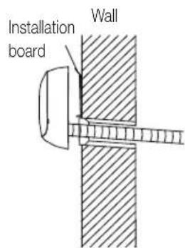
Fig. 7 Fig. 8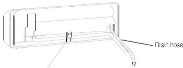
Fixed clamp
7.8 Outdoor unit installation
- If installation brackets for installing outdoor unit are needed, user could buy the brackets from our company or agents (Fig.10).
- Assemble the mounting frame and supports with the attached 6 screws, plain washers, spring washers, and nuts.
- Drill 6 or more holes on the wall according to the feet size of the air conditioner. Determine the locations for mounting left and right supports. Ensure that the left and right supports are on the same level.
Fig. 9
- Fix installation frame on the wall with expansive bolts.
- Fix outdoor unit with 4 bolts on the installation brackets.
- Fittings must be tightly screwed; Connection must be tight and reliable.
- In installing outdoor unit, the body should be hung with ropes to prevent from falling.
- In installing or repair, tools and components should be prevented from falling.
7 Installation manual
- Regularly check the reliability of the installation frame.

Fig. 10
7.9 Tubing connection
- Detach the valve cover of outdoor unit.
- Align flaring nut to the thread center, and screw the nut tightly by hand.
- Screw tightly the flaring nut with torque spanner until the torque spanner produces "click" sound.
- It is recommended to use torque spanner to connect the tubing. If other flexible or fixed spanner is used, it may damage the horn mouth due to improper force.
- The bending angle of the tube should not be too small or the tube may break up, so the service personnel should use tube bender to bend the tube.
- Never let water, dust or sand gets into the pipe.
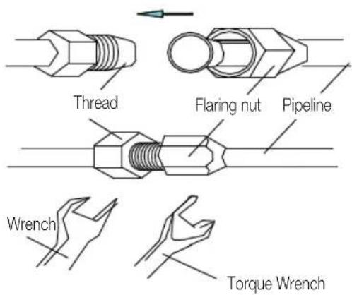
Fig. 11
Table 2
| Tubing size (mm/inch) | Torque (N. m) |
| ∅ 6 (1/4") 15~20 | |
| ∅ 9.52 (3/8") 35~40 | |
| ∅ 12 (1/2") 50~55 | |
| ∅ 15.88 (5/8") 60~75 | |
| ∅ 19.05 (3/4") 80~95 |
7.10 Connection of wires
1. Indoor unit
- Open upward the inlet grid to the greatest extent.
- Remove the electric cover from the unit.
- Loosen the screw at the connection lid. (Fig. 12) • Dismantle the wire pressure plate.
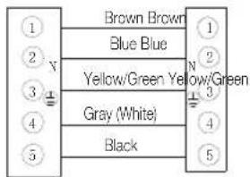
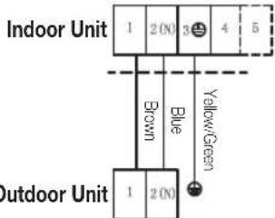
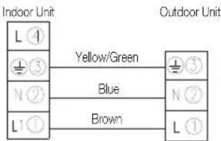
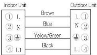
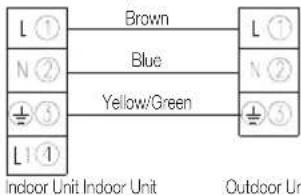
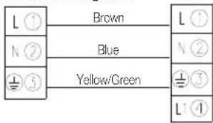
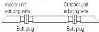
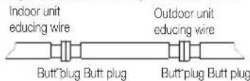
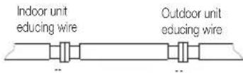
- Connect the power connecting wires and signal control wire separately to the corresponding terminals. (In Fig. 14, please choose the same wiring diagram as the wiring diagram of the unit.)
- Loosen the screw on the earth plate; press the earth wire tightly.
7 Installation manual
- Press tightly the connecting wires of the unit with the lead wire pressure plate.
- Close the connection lid, screw it tightly, and close the inlet grid.
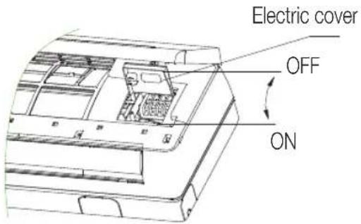
Fig. 12
- Press tightly the connecting wires of the unit with the top pressure plate.
- Remount the electronic device lid to its original position.
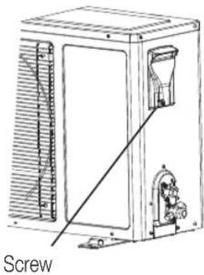
Fig. 13
2. Outdoor unit
- Unscrew and dismantle the electronic device lid (Fig.13). • Dismantle the pressure plate of wire fastener.
- Connect the connecting wires of the unit separately to the corresponding terminals. (Fig.14)
If user wants to prolong or replace the power wire, please do it according to the table (Table 3).
Table 3
| Power connecting wires | Signal control wire | Power cord | ||
| Max. Length 10m 10m 5m | ||||
| 5K/7K/9K/12K | Cross sectional area 5 mm | ≥ 1.0 mm2 | ≥ 1.0 mm2 | ≥ 1.0 mm2 |
| 16K/18K ≥ 1.5 mm | 2 | ≥ 1.5 mm2 | ≥ 1.5 mm2 | |
| 18K/21K/24K/28K ≥ 2 | 2 | ≥ 0.75 mm2 | ≥ 2.5 mm2 | |
7 Installation manual
7K/9K/12K/16K/18K
Power connecting wire Power connecting wire
Indoor Unit Indoor Unit
Outdoor Unit Outdoor Unit
![graph LR A["1"] --> B["1"] C["2"] --> D["2"] E["3"] --> F["3"] G["4"] --> H["4"] I["5"] --> J["5"] B --> K["N"] D --> L["N"] F --> M["N"] H --> N["N"] J --> O["N"]](/content/2026/06/1396286/images/1b818ebc8584ab5cd2a712aa9b78773ad56df2ed99b02c59a8bdb85385598cc1.jpg)
Power Connection Of Indoor And Outdoor Unit

Warning:
- Please connect as the above diagram shown, or it may cause units malfunction. Cut off power source before disassembling connection lid.
- The part "5" will be cancelled for the unit which is no Optional function.
24K/30K/36K/18T3/24T3/30T3/36T3
Power connecting wire

Power connecting wire
Power connecting wire
Power connecting wire
Power connecting wire

Power connecting wire
Signal control wire
Signal control wire
7 Installation manual
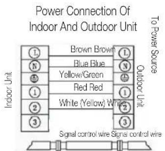
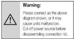
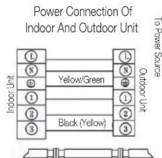
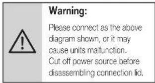
Fig.14

Note:
- Earthing screw must use special screw (stainless machining screws or copper screws M4)
- Ensure that all wires are securely connected, will not lose or separate.
- Ensure that wire connections are carried out according to the wiring diagram of the air conditioner.
- The above figures are only schematic, and they may be slightly different from the actual appliances you select.
7.11 Tube strapping
- Strapping with PVC protective tape must be done carefully, do not damage the pipeline and drain pipe.
- Strapping should start from the lower part of the outdoor unit to the indoor unit.
- Fix the PVC tape with adhesive tape to prevent loosening.
- Drainpipe should slightly slide down outwards to ensure good drainage.
- When the indoor unit is lower than the outdoor unit, bend the tube to proper extent to prevent water draining into the house.
- Fix the tube bundle with tube clamps on the wall.
- Allow enough space between discharge pipe and the ground. Do not put the discharge pipe in water or ditch.
- Seal the external wall holes with sealing gum or putty.
7 Installation manual

Fig.15
7.12 Exhaust
1. Exhausting type
- Make sure that all the tubes of indoor and outdoor unit are connecting well.
- Remove the valve bonnet and the service port valve bonnet from the two-port valve (small pipe shut-off valve) and the three-port valve (large pipe shut-off valve).
- Turn the spool of the two-port valve counter-clockwise 1/4 turn, then close it after 10 seconds.
- Check all connections for leaks.
- Open the two-port and three-port valves for operation.
- Screw the valve bonnet on tightly.
- Check all indoor and outdoor connections for leaks using soap water or a leak detector.
- Put the valve bonnet and valve cover back in place.

2. Pumping type
- Ensure that all tubes of the indoor and outdoor units are properly connected.
- Remove the valve bonnets from the two-way and three-way valves using a spanner; connect the vacuum pump and compound gauge to the service valve bonnet.
- Open the low-pressure switch of the compound gauge, and run the vacuum pump until the internal pressure of the units reaches 10 mmHg.
- After vacuuming, close the low-pressure switch of the compound gauge, then turn off the vacuum pump. Turn the spool of the narrow pipe service valve counter-clockwise 90° using a hexagon wrench, and then close it tightly by turning clockwise after a 10-second pause.
- Check all indoor and outdoor unit connections for leaks using soap water or a leak detector.
- Open the wide and narrow pipe service valves using a hexagon wrench for operation.
- Take off the connection pipeline of the wide pipe service valve.
- Screw the entire valve bonnet tightly with a torque wrench.
- Check with soap water or a leak detector whether there are leaks at all indoor and outdoor connections.
- Put the valve bonnet and lid back into position.

Fig. 17
7 Installation manual
7.13 Drainage
1. No drainage treatment needed
In regions where it becomes cold in the winter, do not install the drain elbow joint to prevent drain water from freezing and causing the fan to be damaged. This drainage treatment is not necessary for cooling-only type air conditioners.
2. When drainage treatment is needed
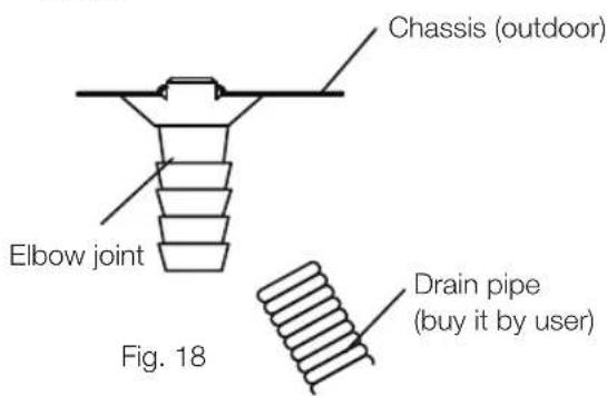
- Please use the drain elbow joint (in the accessory bag). The outdoor unit should be placed on blocks.
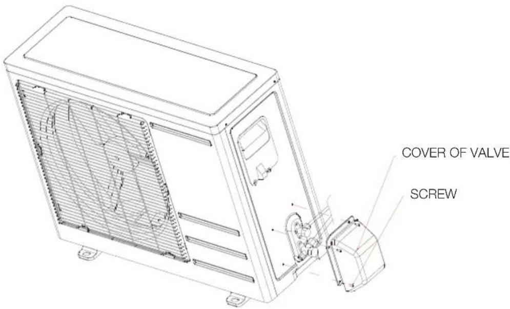
Installation for the cover of the valve:
For the whole unit where an individual cover of the valve is available (refer to the packing list), the installing method is as follows:
After connecting the connection pipes between indoor and outdoor units following the installing method mentioned above, take out the cover of the valve from the accessory bag, and fix it on the side of the outdoor unit with three corresponding screws (inside the accessory bag).
8 European disposal guideline
This appliance contains refrigerant and other potentially hazardous materials. When disposing of this appliance, the law requires special collection and treatment. Do not dispose of this product as household waste or unsorted municipal waste.
When disposing of this appliance, you have the following options:
- Dispose of the appliance at a designated municipal electronic waste collection facility.
- When buying a new appliance, the retailer will take back the old appliance free of charge.
- The manufacturer will take back the old appliance free of charge.
- Sell the appliance to certified scrap metal dealers.
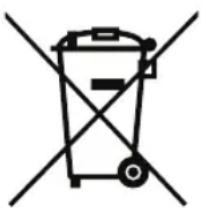
This symbol indicates that this product shall not be disposed of with other household wastes at the end of its service life. Used devices must be returned to an official collection point for recycling of electrical and electronic devices. To find these collection systems, please contact your local authorities or the retailer where the product was purchased. Each household plays an important role in recovering and recycling old appliances. Appropriate disposal of used appliances helps prevent potential negative consequences for the environment and human health.

Special notice
Disposing of this appliance in the forest or other natural surroundings endangers your health and is bad for the environment. Hazardous substances may leak into the ground water and enter the food chain.
9 Installation instructions
9.1 F-Gas instruction
This product contains fluorinated greenhouse gases.
The fluorinated greenhouse gases are contained in hermetically sealed equipment.
Installation, servicing, maintenance, repair, leak checking, or decommissioning of equipment and product recycling should be carried out by natural persons who hold relevant certificates.
If the system has a leakage detection system installed, leakage checks should be performed at least every 12 months to ensure the system operates properly.
If the product must undergo leakage checks, it should specify the inspection cycle and establish and maintain records of the leakage checks.

Note: For hermetically sealed equipment, local air conditioners, window air conditioners, and dehumidifiers, if the CO2 equivalent of fluorinated greenhouse gases is less than 10 tonnes, leakage checks should not be performed.
10 Specifications
| Model name | Indoor unit | BRAE 090 BRAE 090 NG BRAE 090_SKD | BRAE 120 BRAE 120 NG BRAE 120_SKD | BRAE 180 BRAE 180 NG BRAE 180_SKD | BRAE 240 BRAE 240_SKD |
| Outdoor unit | BRAE 091 BRAE 091 NG BRAE 091_SKD | BRAE 121 BRAE 121 NG BRAE 121_SKD | BRAE 181 BRAE 181 NG BRAE 181_SKD | BRAE 241 BRAE 241_SKD | |
| Refrigerant R410a R410a R410a | R410a | ||||
| Total Refrigerant Amount (g) 560 | 650 800 1600 | ||||
| Anti-Electric Class I Class I Class I | I Class I | ||||
| Climate Class T1 T1 T1 T1 | |||||
| Heating Type | Cooling Only | Cooling Only | Cooling Only | Cooling Only | |
| Power Supply Connection | Indoor | Indoor | Indoor | Indoor | |
| Cooling Capacity (Btu/h) [T1] | 9000 | 12000 | 18000 | 24000 | |
| Cooling Capacity (Btu/h) [T3] | / | / | / | / | |
| Cooling Capacity (W) [T1] | 2638 | 3517 | 5275 | 7034 | |
| Cooling Capacity (W) [T3] | / | / | / | / | |
| Heating Capacity (Btu/h) | / | / | / | / | |
| Heating Capacity (W) | / | / | / | / | |
| Energy Efficiency Cooling [T1] | 2.81 | 2.41 | 2.61 | 3.21 | |
| Energy Efficiency Cooling [T3] / | |||||
| Energy Efficiency Heating (W/W) | / | / | / | / | |
| Energy Level-Cooling | / | / | / | / | |
| Energy Level-Heating | / | / | / | / | |
| Annual Energy Consumption (kwh) | / | / | / | / | |
| Power of Electric Heater (W) | / | / | / | / | |
| Cooling Power Input (W) [T1] | 939 | 1459 | 2021 | 2191 | |
| Cooling Power Input (W) [T3] | / | / | / | / | |
| Heating Power Input (W) | / | / | / | / | |
| Voltage/Frequency (V/Hz) | 220-240V~50Hz, 1Ph | 220-240V~50Hz, 1Ph | 220-240V~50Hz, 1Ph | 220-240V~50Hz, 1Ph | |
| Cooling Running Current (A) [T1] | 4.4 | 6.8 | 9.4 | 10.2 | |
| Cooling Running Current (A) [T3] | / | / | / | / | |
| Heating Running Current (A) | / | / | / | / | |
10 Specifications
| Model name | Indoor unit | BRAE 090 BRAE 090 NG BRAE 090_SKD | BRAE 120 BRAE 120 NG BRAE 120_SKD | BRAE 180 BRAE 180 NG BRAE 180_SKD | BRAE 240 BRAE 240_SKD |
| Outdoor unit | BRAE 091 BRAE 091 NG BRAE 091_SKD | BRAE 121 BRAE 121 NG BRAE 121_SKD | BRAE 181 BRAE 181 NG BRAE 181_SKD | BRAE 241 BRAE 241_SKD | |
| Noise Pressure Level - Indoor Unit (dBA) | 40/36/33/30 42/ | 37/33/30 45/42/40/ | 36 48/44/42/39 | ||
| Noise Pressure Level - Outdoor Unit (dBA) | 52 54 55 59 | ||||
| Air flow volume (m3/h) 450/400/360 550/500/450 850/800/700 1200/1050/950 | |||||
| Rated Power Input-EN 60335(W) | 1439 2245 3103 3350 | ||||
| Rated Current Input-EN 60335(A) | 6.7 10.5 14.5 | 15.7 | |||
| Indoor unit Resistance Class - | - | - | - | ||
| Outdoor unit Resistance Class | IPX4 IPX4 IPX4 | IPX4 | |||
| High Pressure Pipe Diameter (mm) | ∅6.35 | ∅6.35 | ∅6.35 | ∅6.35 | |
| Low Pressure Pipe Diameter (mm) | ∅9.52 | ∅12 | ∅12 | ∅15.88 | |
| Max. elevation (m) | 5 | 7 | 7 | 8 | |
| Max. pipe length (m) | 9 | 12 12 15 | |||
| Additional Gas Quantity (g/m) | 15 15 15 20 | ||||
| Power Supply Cord specification (mm2) | 3G1.0mm2 | 3G1.0mm2 | 3G1.5mm2 | 3G2.5mm2 | |
| Indoor & Outdoor Connection Cord (mm2) | 3G1.0mm2 | 3G1.0mm2 | 3G1.5mm2 | 4G2.5mm2 | |
| Indoor Unit (WxHxD) mm | 720*270*201 | 790*270*199 | 900*291*218 | 1025*320*240 | |
| Outdoor Unit (WxHxD) mm | 635*458*240 | 7806543327250 | 820*635*310 | ||
| Indoor Unit Net Weight (kg) | 7,0 | 8,0 | 10,5 | 13,5 | |
| Outdoor Unit Net Weight (kg) 22,0 | 26,0 | 33,0 | 45,0 | ||
10 Specifications
Note:
- Specifications are standard values calculated based on rated operating conditions. They will vary under different working conditions.
- T1 Rated Cooling values are tested under 27/19 (In.) 35/24 (Out.) conditions.
- T3 Rated Cooling values are tested under 29/19 (In.) 46/24 (Out.) conditions. (For T3 Climate models only)
- Rated Heating values are tested under 7/6 (In.) 20/15 (Out.) conditions. (For Heat pump models only)
- Our company has rapid technical improvements. There will be prior notice for any change of technical data. Please read the nameplate on the air conditioner.
Arcelik A.S. Karaagac Cd, No:2-6 34445
Sutluce, Beyoglu, Istanbul, Turkey.
www.beko.com

Fixed air conditioner
User manual

BRAE 090/BRAE 091
BRAE 120/BRAE 121
BRAE 180/BRAE 181
BRAE 240/BRAE 241
BRAE 090 NG/BRAE 091 NG
BRAE 120 NG/BRAE 121 NG
BRAE 180 NG/BRAE 181 NG
BRAE 090_SKD/BRAE 091_SKD
BRAE 120_SKD/BRAE 121_SKD
BRAE 180_SKD/BRAE 181_SKD
BRAE 240_SKD/BRAE 241_SKD
EN
05M-8506243200-2222-02
TABLE OF CONTENTS
FRENCH 3-47
V2203002
BRAE UM
5. SWING button (Oscillation)
8. Quiet button (Silence)

Warning:
Warning:
Fig. 4

Note:

Good ventilation
5 Troubleshooting
Sutluce, Beyoglu, Istanbul, Turkey.
www.beko.com

BRAE 090/BRAE 091
BRAE 120/BRAE 121
BRAE 180/BRAE 181
BRAE 240/BRAE 241
BRAE 090 NG/BRAE 091 NG
BRAE 120 NG/BRAE 121 NG
BRAE 180 NG/BRAE 181 NG
BRAE 090_SKD/BRAE 091_SKD
BRAE 120_SKD/BRAE 121_SKD
BRAE 180_SKD/BRAE 181_SKD
BRAE 240_SKD/BRAE 241_SKD
PT
05M-8506243200-2222-02
INDEX
PORTUGUESE 3-47
V2203002
BRAE UM
Read this user manual carefully!
Dear Customer,
(For gas type R32/R290)

Warning:
Warning:
Fig. 4
Good ventilation

- CONTENTS
- PLEASE READ THIS USER MANUAL FIRST
- MEANINGS OF THE SYMBOLS
- SAFETY INSTRUCTIONS
- PRODUCT INTRODUCTION
- DESCRIPTION OF COMPONENTS
- SERVICE AND MAINTENANCE
- TROUBLESHOOTING
- NORMAL PHENOMENONS
- INSTALLATION MANUAL
- EUROPEAN DISPOSAL GUIDELINE
- INSTALLATION INSTRUCTIONS
- SAFETY PRECAUTIONS
- WARNING
- SYMBOL DESCRIPTION
- INSTALLATION INSTRUCTION
- NEVER INSTALL BY YOURSELF
- PLEASE CONFIRM THE FOLLOWING BEFORE INSTALLATION
- OPERATING INSTRUCTION
- ELECTRICAL SAFETY
- OPERATING CONDITIONS
- TIPS
- ENERGY SAVING GUIDE
- SAFETY INSTRUCTION
- PROTECT FUNCTIONS
- NOTE
- DISPLAY SCREEN
- INDICATOR LIGHT
- REMOTE CONTROLLER
- SLEEP BUTTON
- TURBO BUTTON
- FAN SPEED BUTTON
- TIMER SELECTION BUTTON
- SWING BUTTON
- DISPLAY BUTTON
- CLEAN BUTTON
- QUIET BUTTON
- TEMPERATURE ADJUSTMENT BUTTONS
- ON/OFF BUTTON
- MODE SELECTION BUTTON
- REMOTE CONTROLLER DISPLAY
- UVC DISPLAY
- I FEEL DISPLAY
- SLEEP MODE DISPLAY
- SETTING TEMP DISPLAY
- INSTRUCTIONS FOR REMOTE CONTROLLER
- CLEANING THE FRONT PANEL AND REMOTE CONTROLLER
- CLEAN AIR FILTER
- NO USE FOR LONG TIME
- RECOMMENDATIONS FOR ENERGY SAVING
- APPROPRIATE TEMP SETTING
- AVOID DIRECT SUNLIGHT
- AIR CONDITIONER IS IN ERROR
- REMOTE CONTROLLER IS IN ERROR
- NORMAL PHENOMENA
- INSTALLATION GUIDE
- INSTALLATION OF ACCESSORIES
- POSITION FOR INDOOR UNIT
- POSITION FOR OUTDOOR UNIT
- TUBING SELECTION
- FIXING INSTALLATION PANEL
- INDOOR UNIT INSTALLATION
- OUTDOOR UNIT INSTALLATION
- TUBING CONNECTION
- CONNECTION OF WIRES
- INDOOR UNIT
- OUTDOOR UNIT
- TUBE STRAPPING
- EXHAUST
- EXHAUSTING TYPE
- PUMPING TYPE
- DRAINAGE
- NO DRAINAGE TREATMENT NEEDED
- WHEN DRAINAGE TREATMENT IS NEEDED
- SPECIAL NOTICE
- F-GAS INSTRUCTION
- SPECIFICATIONS
- FIXED AIR CONDITIONER
- TABLE OF CONTENTS
- SWING BUTTON (OSCILLATION)
- QUIET BUTTON (SILENCE)
- INDEX
- READ THIS USER MANUAL CAREFULLY
Brand : BEKO
Model : BRAE 181
Category : Air conditioner