
GA-990FXA-UD7 - Motherboard GIGABYTE - Free user manual and instructions
Find the device manual for free GA-990FXA-UD7 GIGABYTE in PDF.

User questions about GA-990FXA-UD7 GIGABYTE
0 question about this device. Answer the ones you know or ask your own.
Ask a new question about this device
Download the instructions for your Motherboard in PDF format for free! Find your manual GA-990FXA-UD7 - GIGABYTE and take your electronic device back in hand. On this page are published all the documents necessary for the use of your device. GA-990FXA-UD7 by GIGABYTE.
USER MANUAL GA-990FXA-UD7 GIGABYTE
- The sequence of installation may differ depending on the type of case and devices used. The installation instructions below apply to GIGABYTE's desktop systems and are for reference only.
• Refer to the user's manual included for detailed motherboard specifications. - Before installing the devices, make sure they are compliant with the connectors on your computer.
- Before installing the devices, be sure to turn off the devices and your computer. Unplug the power cord from the power outlet to prevent damage to the devices and the system components.
- Place the computer system on a stable surface to prevent improper installation resulted from shaking.

Installing a CPU and CPU Cooler
A. Installing an Intel CPU (skip this step if the motherboard has a built-in CPU)
A-1 Refer to the following instructions based on your CPU specifications:
- Type A:
natural_image
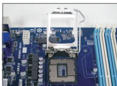
Close-up of a blue computer motherboard with a central processor and visible wiring (no text or symbols)Lift the CPU socket lever and the metal load plate will be lifted as well.
a. If the protective socket cover is fastened on the CPU socket, remove it first.
b. If the protective socket cover is fastened on the metal load plate, do not remove it at this stage. The socket cover may pop off from the load plate automatically during the process of re-engaging the lever after you insert the CPU.
- Type B:
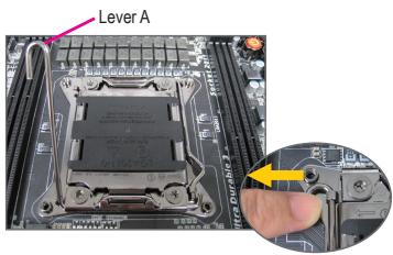
Push lever A (closest to the "☐" marking) down and away from the socket to release it. Then push lever B (closest to the "☐" marking) down and away from the socket and lift it. Gently press lever A to allow the load plate to rise. Open the load plate.
text_image
Lever A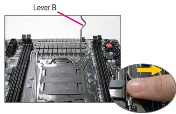
text_image
Lever BA-2 Hold the CPU with your thumb and index fingers. Align the CPU pin one marking (triangle) with the pin one corner of the CPU socket (or you may align the CPU notches with the socket alignment keys) and gently insert the CPU into position.
A-3 Once the CPU is properly inserted, replace the load plate and push the CPU socket lever back into its locked position. Once the type B is properly inserted, carefully replace the load plate. Then secure lever B under its retention tab. The socket cover may pop off from the load plate during the process of engaging the lever. Finally, secure lever A under its retention tab to complete the installation of the CPU.

For detailed instructions on installing the CPU, please refer to the user's manual.
B. Installing an AMD CPU (skip this step if the motherboard has a built-in CPU)
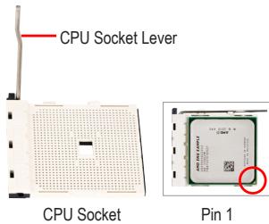
B-1 Completely raise the CPU socket lever. Align the CPU pin one (small triangle marking) with the triangle marking on the CPU socket and gently insert the CPU into the socket. Make sure that the CPU pins fit perfectly into their holes.
B-2 Once the CPU is positioned into its socket, place one finger down on the middle of the CPU, lowering the socket lever and latching it into the fully locked position.
text_image
CPU Socket Lever CPU Socket Pin 1
- Do not force the CPU into the CPU socket. The CPU cannot fit in if oriented incorrectly. Adjust the CPU orientation if this occurs.
- DO NOT touch socket contacts. To protect the CPU socket, always replace the protective socket cover when the CPU is not installed.
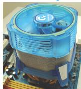
C. Installing the CPU Cooler
natural_image
Close-up of a blue CPU fan with heatsink and cooling fins, mounted on a computer motherboard (no visible text or symbols)
natural_image
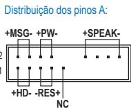
Close-up of a yellow plastic connector mounted on a blue circuit board (no visible text or symbols)C-1 Before installing the CPU cooler, please first add a thin layer of heat sink paste on the surface of the CPU. Then install the cooler (refer to the installation manual for your CPU cooler).
C-2 Connect the CPU cooler cable to the CPU_FAN connector located on the motherboard so that the cooler can properly function to prevent the CPU from overheating.
Step
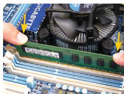
2 Installing Memory
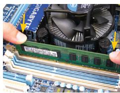
natural_image
Close-up of hands holding a green RAM module on a computer motherboard with a CPU fan in the background (no visible text or symbols)Note the orientation of the memory module. Spread the retaining clips at both ends of the memory socket. Place the memory module on the socket. As indicated in the picture on the left, place your fingers on the top edge of the memory, push down on the memory and insert it vertically into the memory socket. The clips at both ends of the socket will snap into place when the memory module is securely inserted.
Step
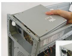
3 Preparing the Case and Installing a Power Supply
natural_image
Close-up of a computer tower with visible power lines and a hand adjusting its cover (no text or symbols)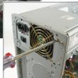
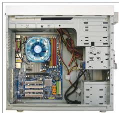
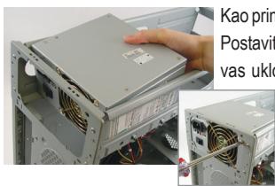
Using the GIGABYTE desktop system as the demonstration example, please first remove both sides and the lid of the case in order to install the power supply. Place the power supply in the correct place in the case and secure it with screws. Installation and placement of the power supply may differ depending on the type of case used.

To ensure sufficient power can be supplied to your system, it is recommended that a power supply of good quality be used. If a power supply is used that does not provide the required power, the result can lead to an unstable or unbootable system.
Step
4
Installing the Motherboard
natural_image
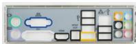
Interior view of a computer tower case showing CPU socket, motherboard, and drive bays (no visible text or labels)Remove the original I/O shield from the back of the case and replace it with the motherboard I/O shield. Place the motherboard within the case by positioning it into its I/O shield. Align the mounting screw holes on the motherboard with their corresponding mounting holes on the case. Secure the motherboard in place with screws.
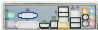
I/O Shield
Step
5
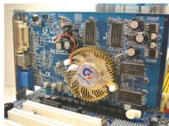
Installing an Expansion Card
natural_image
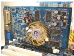
Close-up of a blue computer motherboard with visible circuitry and components (no readable text or symbols)PCI Express Graphics Card
Locate an expansion slot that supports your card and remove the slot cover from the case back panel. Then insert the expansion card into the slot. Secure the expansion card's bracket to the case back panel with a screw.

Before purchasing an expansion card, check the length of the card, making sure it can fit into your case.
• Make sure that the expansion card is fully seated in its slot.
Step
6
Installing IDE and SATA Devices
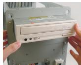
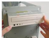
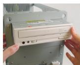
Installing an Optical Drive
6-1 Install your optical drives, such as DVD-ROM and CD-ROM drives.
Remove the 5.25" drive bay cover from the front of the case. Mount the optical drive in the 5.25" drive bay and secure it with screws.
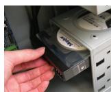
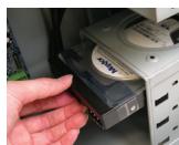
Installing a Hard Drive
6-2 Install your IDE and SATA hard drives. Install the hard drive into a drive bay within the case and secure it with screws.

- One motherboard IDE connector can connect up to two IDE devices. Prior to installation, check the jumper settings (master and slave) on your IDE devices.
- If more than one hard drive is installed, enter system BIOS Setup to set the hard drive boot sequence.

Connecting Cables to Internal Connectors
7-1 Connect cables to internal connectors and headers on the motherboard, including IDE/SATA connectors, and front panel audio, USB, IEEE 1394 headers, etc.
7-2 Attach the front panel module (differs depending on the case design, consisting of power indicator, hard drive activity indicator, speakers, reset switch, power switch, etc.) from the case to the front panel header (F_PANEL) on the motherboard.
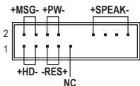
Front Panel Header
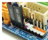
Pin Assignments A:
text_image
+MSG- +PW- +SPEAK- 2 1 +HD- -RES+ NCPin Assignments B:
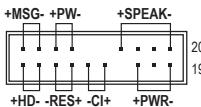
MSG: Message/Power/Sleep LED
PWR: Power LED
PW: Power Switch
SPEAK: Speaker
HD: Hard Drive Activity LED
RES: Reset Switch
CI: Chassis Intrusion Header
(Note) The pin assignments for the front panel header may differ by model. Refer to the motherboard user's manual for the actual pin assignments.

Connecting Peripherals
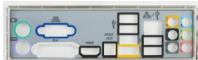
Back Panel of the Case
text_image
Power Supply PS/2 Keyboard Port DVI-D Port HDMI Port eSATA Port IEEE 1394 Port Audio Jacks Power Switch Power Cord Connector PS/2 Mouse Port D-Sub Port S/PDIF Connector USB Ports RJ-45 LAN Port External Graphics CardOnce the steps above have been completed, connect the peripheral devices to the computer, such as the keyboard, mouse, monitor, etc. Then connect the power, turn on the system, and install all required software.

natural_image
Close-up of a blue computer motherboard with a central processor and attached circuit board (no visible text or symbols)natural_image
Close-up of a blue CPU fan with heatsink and cooling tower (no visible text or symbols)
natural_image
Close-up of a white ceramic connector with red wires inserted into a blue circuit board (no visible text or symbols)natural_image
Close-up of a computer motherboard with a green RAM module and a CPU fan, no visible text or symbols.natural_image
Interior view of a computer tower showing CPU socket, motherboard, and drive bays (no visible text or labels)natural_image
Close-up of a computer motherboard with visible circuitry and components (no readable text or symbols)PCI Express Grafikkarte
natural_image
Close-up of a blue computer motherboard with a white electronic component mounted on top, surrounded by circuit boards and connectors (no visible text or symbols)natural_image
Close-up of a blue CPU fan with heatsink and cooling fins, mounted on a motherboard (no visible text or symbols)
natural_image
Close-up of a white ceramic connector with red wires inserted into it, placed on a blue circuit board (no visible text or symbols)natural_image
Close-up of hands operating a computer motherboard with a green RAM module and a cooling fan (no visible text or symbols)natural_image
Interior view of a computer tower showing CPU socket, motherboard, and drive bays (no visible text or labels)natural_image
Close-up of a computer motherboard with visible circuitry and components (no readable text or symbols)natural_image
Close-up of a blue computer motherboard with a white plastic component and multiple electronic components (no visible text or symbols)natural_image
Close-up of a blue CPU fan with heatsink and cooling element (no visible text or symbols)
natural_image
Close-up of a yellow connector with red wires inserted into a blue circuit board (no visible text or symbols)natural_image
Close-up of a computer motherboard with a green RAM module and a fan, no visible text or symbolsnatural_image
Interior view of a computer tower showing CPU socket, motherboard, and drive bays (no visible text or labels)natural_image
Close-up of a computer motherboard with visible circuitry and components (no readable text or symbols)Placa gráfica PCI Express
Conector do painel frontal
natural_image
Close-up of a blue computer motherboard with a central processor and visible circuitry (no text or symbols)natural_image
Close-up of a blue CPU fan with heatsink and cooling tower, mounted on a motherboard (no visible text or symbols)
natural_image
Close-up of a yellow connector with red wires inserted into a blue circuit board (no visible text or symbols)natural_image
Close-up of hands holding a green RAM module with a cooling fan and CPU socket in the background (no visible text or symbols)natural_image
Interior view of a computer tower showing CPU socket, motherboard, and drive bays (no visible text or labels)natural_image
Close-up of a computer motherboard with visible circuitry and components (no readable text or symbols)natural_image
Close-up of a blue computer motherboard with visible CPU socket and circuit board (no text or symbols)natural_image
Close-up of a blue CPU fan with heatsink and cooling tower, mounted on a computer motherboard (no visible text or symbols)
natural_image
Close-up of a yellow connector with red wires inserted into a blue circuit board (no visible text or symbols)natural_image
Close-up of hands holding a green RAM module on a computer motherboard with a cooling fan visible (no text or symbols)natural_image
Interior view of a computer tower showing CPU socket, motherboard, and drive bays (no visible text or labels)natural_image
Close-up of a computer motherboard with visible circuitry and components (no readable text or symbols)natural_image
Close-up of a blue computer motherboard with a central CPU socket and cooling unit (no visible text or symbols)natural_image
Close-up of a blue CPU fan with heatsink and cooling fins, mounted on a computer motherboard (no visible text or symbols)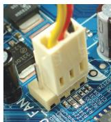
natural_image
Close-up of a yellow and red connector on a blue circuit board (no visible text or symbols)natural_image
Close-up of hands operating a computer motherboard with a green RAM module and a cooling fan (no visible text or symbols)natural_image
Close-up of a computer tower with a hand adjusting its front panel (no visible text or symbols)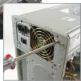
natural_image
Interior view of a computer tower case showing CPU socket, motherboard, and drive bays (no visible text or labels)natural_image
Close-up of a computer motherboard with visible circuitry and components (no readable text or symbols)natural_image
Close-up of a blue computer motherboard with a white plastic component and multiple electronic components (no visible text or symbols)natural_image
Close-up of a blue CPU fan with heatsink and motherboard (no visible text or symbols)
natural_image
Close-up of a white ceramic connector with red wires inserted into a blue circuit board (no visible text or symbols)natural_image
Close-up of hands operating a computer motherboard with a green RAM module and a fan, no visible text or symbols.natural_image
Close-up of a computer tower with visible power lines and connectors, showing part assembly (no text or symbols)natural_image
Interior view of a computer tower showing CPU socket, motherboard, and drive bays (no visible text or labels)natural_image
Close-up of a computer motherboard with visible circuitry and electronic components (no readable text or symbols)natural_image
Close-up of a blue computer motherboard with a central CPU socket and a metallic bracket (no visible text or symbols)text_image
CPU yuva Kolu CPU yuva İlk CPU pini
natural_image
Close-up of a blue CPU fan with heatsink and cooling tower (no visible text or symbols)
natural_image
Close-up of a white ceramic connector with red wires inserted into a blue circuit board (no visible text or symbols)natural_image
Close-up of a computer motherboard with a green RAM module and a fan, no visible text or symbolsnatural_image
Close-up of a computer tower with visible power connectors and ventilation slots, showing no text or symbols on the main subject.natural_image
Interior view of a computer tower showing CPU socket, motherboard, and drive bays (no visible text or labels)natural_image
Close-up of a computer motherboard with visible circuitry and components (no readable text or symbols)PCI Express Ekran Kartı
natural_image
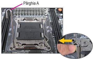
Close-up of a blue computer motherboard with a white plastic component and multiple electronic components (no visible text or symbols)Push lever A (closest to the "☐" marking) down and away from the socket to release it. Then push lever B (closest to the "☐" marking) down and away from the socket and lift it. Gently press lever A to allow the load plate to rise. Open the load plate.
text_image
Pârghia A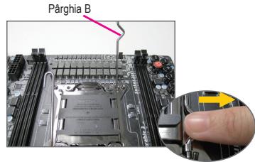
text_image
Pârghia Bnatural_image
Close-up of a blue CPU fan with heatsink and cooling element (no visible text or symbols)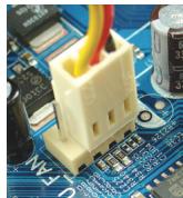
natural_image
Close-up of a yellow connector with red wires inserted into a blue circuit board (no visible text or symbols)natural_image
Close-up of a computer motherboard with a green RAM module and a fan, no visible text or symbolsnatural_image
Close-up of a computer tower with visible power connectors and ventilation slots, no text or symbols present.natural_image
Interior view of a computer tower showing CPU socket, motherboard, and drive bays (no visible text or labels)natural_image
Close-up of a computer motherboard with visible circuitry and components (no readable text or symbols)HD: LED activate hard disk
natural_image
Close-up of a blue computer motherboard with a central processor and cooling tower (no visible text or symbols)natural_image
Close-up of a blue CPU fan with heatsink and cooling tower (no visible text or symbols)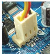
natural_image
Close-up of a yellow connector with red wires inserted into a blue circuit board (no visible text or symbols)natural_image
Close-up of hands holding a green RAM module on a computer motherboard with a CPU fan in the background (no visible text or symbols)natural_image
Interior view of a computer tower showing CPU socket, motherboard, and drive bays (no visible text or labels)natural_image
Close-up of a computer motherboard with visible circuitry and components (no readable text or symbols)natural_image
Close-up of a blue computer motherboard with a central processor and cooling tower (no visible text or symbols)natural_image
Close-up of a blue CPU fan with heatsink and cooling element (no visible text or symbols)
natural_image
Close-up of a white ceramic connector with red wires inserted into a blue circuit board (no visible text or symbols)natural_image
Close-up of hands holding a green RAM module on a computer motherboard with a blue CPU socket and fan in the background (no visible text or symbols)natural_image
Close-up of a computer tower with visible cooling fans and a hand placing a component (no text or symbols on the main image)natural_image
Interior view of a computer tower showing CPU socket, motherboard, and drive bays (no visible text or labels)natural_image
Close-up of a computer motherboard with visible circuitry and components (no readable text or symbols)PCI Express videokártya
natural_image
Close-up of a blue computer motherboard with a white plastic component mounted on top (no visible text or symbols)natural_image
Close-up of a blue CPU fan with heatsink and cooling tower, mounted on a computer motherboard (no visible text or symbols)
natural_image
Close-up of a white electronic component with red wires inserted into it, placed on a circuit board (no visible text or symbols)natural_image
Close-up of hands operating a computer motherboard with a green RAM module and a cooling fan (no visible text or symbols)natural_image
Close-up of a computer tower case with visible cooling fans and wiring, no text or symbols present.natural_image
Interior view of a computer tower showing CPU socket, motherboard, and drive bays (no visible text or labels)natural_image
Close-up of a computer motherboard with visible circuitry and components (no readable text or symbols)natural_image
Close-up of a blue computer motherboard with a central processor and visible circuitry (no text or symbols)natural_image
Close-up of a blue CPU fan with heatsink and cooling unit, mounted on a computer motherboard (no visible text or symbols)
natural_image
Close-up of a white ceramic connector with red wires inserted into it, placed on a blue circuit board (no visible text or symbols)natural_image
Close-up of hands operating a computer motherboard with a green RAM module and a blue CPU fan (no visible text or symbols)natural_image
Interior view of a computer tower showing CPU socket, motherboard, and drive bays (no visible text or labels)natural_image
Close-up of a computer motherboard with visible circuitry and components (no readable text or symbols)natural_image
Close-up of a blue computer motherboard with a white plastic component mounted on top, surrounded by circuit boards and connectors (no visible text or symbols)natural_image
Close-up of a blue CPU fan with heatsink and cooling tower (no visible text or symbols)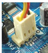
natural_image
Close-up of a white electronic component with red wires inserted into a blue circuit board (no visible text or symbols)natural_image
Close-up of hands operating a computer motherboard with a green RAM module and a cooling fan (no visible text or symbols)Obratite pažnju na to kako je okrenut memorijski modul. Raširite klipove koji drže memoriju sa obe strane podnožja za memoriju. Smestite memorijski modul u podnožje. Kako je prikazano na slici levo, stavite prste na vrh memorije, pritisnite memoriju i ubacite je vertikalno u podnožje za memoriju. Klipovi sa obe strane podnožja će se vratiti na mesto kada je memorijski modul ispravno ubačen.
Korak
3 Priprema kućišta i instaliranje napajanja
natural_image
Close-up of a computer tower with visible fan blades and cooling fins, showing no text or symbols on the main components.natural_image
Interior view of a computer tower showing CPU socket, motherboard, and drive bays (no visible text or labels)Uklonite originalni I/O štit sa poledine kućišta i zamenite ga I/O štitom matične ploče. Stavite matičnu ploču u kućište smeštajući je na svoj I/O štit. Poravnajte rupice za montiranje na matičnoj ploči sa odgovarajućim rupicama za montiranje na kućištu. Pričvrstite matičnu ploču na mesto šrafovima.
I/O štit
Korak
5 Instaliranje dodatnih kartica

natural_image
Close-up of a computer motherboard with visible circuitry and components (no readable text or symbols)PCI EXpress grafička kartica
Pronađite određeni port (slot) koji podržava vašu karticu i uklonite poklopac porta (slota) sa zadnje strane kućišta. Potom ubacite karticu u port (slot). Pričvrstite spoj ekspanzione kartice za poleđinu kućišta šrafom.

- Pre kupovine ekspanzione kartice, proverite dužinu kartice da bi bili sigurni da može da stane u kućište.
Proverite da li je grafička kartica potpuno ulegla u prorez.
Korak
6 Instaliranje IDE i SATA uređaja
Instaliranje optičkog uređaja
6-1 Instalirajte svoje optičke uređaje, poput DVD-ROM i CD-ROM uređaja.
Uklonite poklopac za prorez uređaja veličine 5.25" sa prednje strane kućišta.
Ubacite optički uređaj veličine 5.25" u rupu i pričvrstite ga šrafovima.
Instaliranje hard diska
6-2 Instalirajte svoje IDE i SATA hard diskove. Instalirajte hard disk u prostor za hard disk u kućištu i pričvrstite ga šrafovima.

- Jedan IDE konektor na matičnoj ploči može da poveže do dva IDE uređaja. Pre instalacije, proverite kako su podešeni džamperi (master i slejv) na vašim IDE uređajima.
- Ukoliko ste instalirali više od jednog hard diska, uđite u BIOS podešavanja da bi odredili redosled podizanja hard diskova.

Povezivanje Kablova na Interne Konektore
7-1 Povežite kablove za unutrašnje konektore i zaglavlja na matičnoj ploči, uključujući IDE/SATA konektore i audio prednjeg panela, USB, IEEE 1394 zaglavlja itd.
7-2 Pričvrstite modul prednjeg panela (razlikuje se u zavisnosti od dizajna kućišta i sastoji se od indikatora napajanja, indikatora aktivnosti hard diska, zvučnika, prekidača za resetovanje, prekidača za uključivanje itd.) sa kućišta za zaglavlje prednjeg panela (F_PANEL) na matičnoj ploči.
natural_image
Close-up of a blue computer motherboard with a central CPU socket and surrounding circuit boards (no visible text or symbols)natural_image
Close-up of a blue CPU fan with heatsink and motherboard (no visible text or symbols)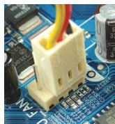
natural_image
Close-up of a white electronic component with red wires inserted into it, placed on a blue circuit board (no visible text or symbols)C- 1 Prije ugradnje hladnjaka procesora, premažite procesor tankim slojem termovodljive paste. Zatim ugradnje hladnjak (pogledajte priručnik za ugradnje hladnjaka procesora).
C- 2 Spojite kabel hladnjaka procesora na CPU_FAN priključak na matičnoj ploči, kako bi hladnjak radio ispravno i kako ne bi došlo do pregrijavanja procesora..

Instalacija memorije
natural_image
Close-up of hands cleaning a motherboard with a green RAM module and a CPU fan (no visible text or symbols)Zapamtite usmjerenje memorijskog modula. Raširite kopče na obje strane memorijske utičnice. Umetnite memorijski modul u utičnicu. Kako je prikazano na slici lijevo, postavite svoje prste na vrh memorije, gurnite je prema dolje i umetnite je vertikalno u memorijsku utičnicu. Kopče na oba kraja utičnice će uskočiti na mjesto kad memorijski modul sjedne čvrsto na svoje mjesto.

natural_image
Interior view of a computer tower showing CPU socket, motherboard, and drive bays (no visible text or labels)Skinite originalni poklopac I/O sa stražnje strane kućišta i zamijenite ga poklopcem matične ploče I/O. Postavite matičnu ploču unutar kućišta, tako da je pozicionirate u I/O štitniku. Poravnajte rupe vijaka za ugradnju na matičnoj ploči s odgovarajućim rupama za montažu na kućištu. Vijcima pričvrstite matičnu ploču na njeno mjesto.
I/O štitnik
Korak
5 Instaliranje kartice za proširenje
natural_image
Close-up of a computer motherboard with visible circuitry and components (no readable text or symbols)PCI Express grafička kartica
Pronađite utor za proširenje koji podržava vašu karticu i skinite poklopac utora sa stražnje strane kućišta. Zatim umetnite karticu za proširenje u utor. Pričvrstite nosač kartice za proširenje na stražnju ploču kućišta pomoću vijka.

Prije nego kupite karticu za proširenje, provjerite duljinu kartice i da li stane u kućište.
Provjerite je li kartica za proširenje u potpunosti sjela u utor.
Korak
6 Instaliranje IDE i SATA uređaja
Instaliranje optičkog uređaja
6-1 Instalirajte optičke uređaje kao što su DVD-ROM i CD-ROM.
Izvadite ležište za 5,25" pogon s prednje strane kućišta. Ugradite optički pogon u ležište uređaja 5,25" i stegnite ga vijcima.
Instaliranje hard diska
natural_image
Interior view of a computer tower case showing CPU socket, motherboard, and drive bays (no visible text or labels)(I/O shield) כרְשָׁהִיַעֹן (II)
תְרָה לַעֹלְרָה
5
natural_image
Close-up of a computer motherboard with visible circuitry and components (no text or symbols)PCI Express
natural_image
Close-up of a blue CPU fan with heatsink and cooling fins, mounted on a motherboard (no visible text or symbols)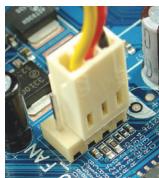
natural_image
Close-up of a yellow plastic connector mounted on a blue circuit board (no visible text or symbols)תְרָה בַרִי הַלְרָה
2
natural_image
Close-up of hands installing a green RAM module on a computer motherboard with a cooling fan (no visible text or symbols)natural_image
Close-up of a hand holding a computer power supply unit with visible fan and drive lights (no text or symbols)natural_image
Close-up of a blue computer motherboard with visible CPU socket and RAM slots (no text or symbols):В λιο •
natural_image
Close-up of a computer motherboard with a highlighted CPU socket and a close-up view showing the keyboard (no text or symbols visible)הכלה 2-ה הכלה 2-ה
3-1
. כרִי אַבְרָה