
GA-8PE800 PRO-R - Motherboard GIGABYTE - Free user manual and instructions
Find the device manual for free GA-8PE800 PRO-R GIGABYTE in PDF.


User questions about GA-8PE800 PRO-R GIGABYTE
0 question about this device. Answer the ones you know or ask your own.
Ask a new question about this device
Download the instructions for your Motherboard in PDF format for free! Find your manual GA-8PE800 PRO-R - GIGABYTE and take your electronic device back in hand. On this page are published all the documents necessary for the use of your device. GA-8PE800 PRO-R by GIGABYTE.
USER MANUAL GA-8PE800 PRO-R GIGABYTE
When you installing AGP card, please make sure the following notice is fully understood and practiced. If your AGP card has "AGP 4X(1.5V) notch"(show below), please make sure your AGP card is AGP 4X(1.5V).


Caution: AGP 2X(3.3V) card is not supported by Intel® 845(GE/PE) / 845(E/G) / 850(E). You might experience system unable to boot up normally. Please insert an AGP 4X(1.5V) card
Example 1: Diamond Vipper V770 golden finger is compatible with 2X/4X mode AGP slot. It can be switched between AGP 2X(3.3V) or 4X (1.5V) mode by adjusting the jumper. The factory default for this card is 2X(3.3V).
The GA-8PE800 Ultra / GA-8PE800 Pro(-R) (or any AGP 4X only) motherboards might not function properly, if you install this card without switching the jumper to 4X(1.5) mode in it.
Example 2: Some ATI Rage 128 Pro graphics cards made by "Power Color", the graphics card manufacturer & some SiS 305 cards, their golden finger is compatible with 2X(3.3V)/4X(1.5V) mode AGP slot, but they support 2X(3.3V) only. The GA-8PE800 Ultra / GA-8PE800 Pro(-R) (or any AGP 4X only) motherboards might not function properly, if you install this card in it.
Note : Although Gigabyte's AG32S(G) graphics card is based on ATi Rage 128 Pro chip, the design of AG32S(G) is compliance with AGP 4X(1.5V) specification. Therefore, AG32S (G)will work fine with Intel®845(GE/PE) /845(E/G) / 850(E) based motherboards.

Before you install PCI cards, please remove the Dual BIOS label from PCI slots if there is one.

The author assumes no responsibility for any errors or omissions that may appear in this document nor does the author make a commitment to update the information contained herein.
Third-party brands and names are the property of their respective owners.
Please do not remove any labels on motherboard, this may void the warranty of this motherboard.
Due to rapid change in technology, some of the specifications might be out of date before publication of this booklet.

WARNING: Never run the processor without the heatsink property and firmly attached. PERMANENT DAMAGE WILL RESULT!
Declaration of Conformity
We, Manufacturer/Importer
(full address)
G.B.T. Technology Trading GmbH
declare that the product
(descrip tion of the apparatus, system, installation to which it refers)
Mother Board
GA-8PE800 Ultra / GA-8PE800 Pro
is in conformity with
(reference to the specification under which conformity is declared)
in accordance with 89/336 EEC-EMC Directive
| ☐ EN 55011 | Limits and methods of measurement of radio disturbance characteristics of industrial, scientific and medical (ISM high frequency equipment | ☐ EN 61000-3-2* ☑ EN 60555-2 | Disturbances in supply systems cause by household appliances and similar electrical equipment "Harmonics" |
| ☐ EN 55013 | Limits and methods of measurement of radio disturbance characteristics of broadcast receivers and associated equipment | ☐ EN 61000-3-3* ☑ EN 60555-3 | Disturbances in supply systems cause by household appliances and similar electrical equipment "Voltage fluctuations" |
| ☐ EN 55014 | Limits and methods of measurement of radio disturbance characteristics of household electrical appliances, portable tools and similar electrical apparatus | ☐ EN 50081-1 | Generic emission standard Part 1: Residual commercial and light industry |
| ☐ EN 50082-1 | Generic immunity standard Part 1: Residual commercial and light industry | ||
| ☐ EN 55015 | Limits and methods of measurement of radio disturbance characteristics of fluorescent lamps and luminaries | ☐ EN 55081-2 | Generic emission standard Part 2: Industrial environment |
| ☐ EN 55020 | Immunity from radio interference of broadcast receivers and associated equipment | ☐ EN 55082-2 | Generic emission standard Part 2: Industrial environment |
| ☐ EN 55022 | Limits and methods of measurement of radio disturbance characteristics of information technology equipment | ☐ ENV 55104 | Immunity requirements for hou sehold appliances tools and similar apparatus |
| ☐ DIN VDE 0855 | Cabled distribution systems; Equipment for receiving and/or distribution from sound and television signals | ☐ EN50091-2 | EMC requirements for uninterruptible power systems (UPS) |
| ☐ part 10 | |||
| ☐ part 12 |

(EC conformity marking)
The manufacturer also declares the conformity of above mentioned product
with the actual required safety standards in accordance with LVD 73/23 EEC
EN 60065 Safety requirements for mains operated EN 60950 Safety for information technology equipment
electronic and related apparatus for including electrical bussiness equipment
household and similar general use
EN 60335 Safety of household and similar
electrical appliances
Manufacturer/Importer
Date: Jan. 24, 2003
Signature:
Name:
Jimmy Huang
Timmy Huang
DECLARATION OF CONFORMITY
Per FCC Part 2 Section 2.1077(a)

Responsible PartName: G.B.T. INC. (U.S.A.)
Address: 17358 Railroad Street
City of Industry, CA 91748
Phone/FaxNo: (818) 854-9338/ (818) 854-9339
hereby declares that the product
Product Name: Motherboard
Model Number: GA-8PE800 Ultra/GA-8PE800 Pro
Conforms to the following specifications:
FCC Part 15, Subpart B, Section 15.107(a) and Section 15.109
(a),Class B Digital Device
Supplementary Information:
This device complies with part 15 of the FCC Rules. Operation is subject to the following two conditions: (1) This device may not cause harmful and (2) this device must accept any inference received, including that may cause undesired operation.
Representative Person's Name: ERIC LU
Signature: Eric Lu
Date: Jan. 24, 2003
GA-8PE800 Ultra / Pro(-R)
P4 Titan Motherboard
USER'S MANUAL
Pentium®4 Processor Motherboard
Rev. 1103
12ME-8PE800U-1103
Table of Content
Item Checklist 4
WARNING! 4
Chapter 1 Introduction 5
Features Summary 5
GA-PE800 Ultra / Pro(-R) Motherboard Layout 8
Block Diagram 9
Chapter 2 Hardware Installation Process 11
Step 1: Install the Central Processing Unit (CPU) 12
Step 1-1:CPU Installation 12
Step 1-2: CPU Heat Sink Installation 13
Step 2: Install memory modules 14
Step 3: Install expansion cards 16
Step 4: Connect ribbon cables, cabinet wires, and power supply 17
Step 4-1: I/O Back Panel Introduction 17
Step 4-2: Connectors & Jumper Setting Introduction 19
Chapter 3 BIOS Setup 35
The Main Menu (For example: BIOS Ver.:F1) 36
Standard CMOS Features 38
AdvancedBIOSFeatures 41
Integrated Peripherals 43
Power Management Setup 49
PnP/PCI Configurations 52
PC Health Status 53
Frequency/Voltage Control 55
Top Performance 57
Select Language 58
Load Fail-Safe Defaults 59
Load Optimized Defaults 60
Set Supervisor/User Password 61
Save & Exit Setup 62
Exit Without Saving 63
Chapter 4 Technical Reference 65
@BIOS Introduction 65
Easy Tune 4^TM Introduction 66
Face-Wizard Utilities Installation 67
BIOS Flash PROCEDURE 68
2-/4-/6-Channel Audio Function Introduction 88
Chapter 5 Appendix 95
Item Checklist
The GA-8PE800 Ultra /Pro(-R) motherboard
CD for motherboard driver & utility
GA-8PE800 Ultra /Pro(-R) user's manual
Quick PC Installation Guide
ITERAIIDManual
SATA RAID Manual
Motherboard Settings Label
GC-SATA Card (Optional)
Manual; SATA cable x1; Power cable x 1)
IDE cable x1 / Floppy cable x 1*
IDE cable x3 / Floppy cable x 1 念
2 Port USB Cable x 2
忍 IEEE 1394 Cable x 1
SATA cable x2
Audio combo kit x1
(SURROUND-Kit + SPDIF Out KIT)
SPDIFKitx1(SPDIFOutKIT)
I/O Shield

CAUTION
Computer motherboards and expansion cards contain very delicate Integrated Circuit (IC) chips. To protect them against damage from static electricity, you should follow some precautions whenever you work on your computer.
- Unplug your computer when working on the inside.
- Use a grounded wrist strap before handling computer components. If you do not have one, touch both of your hands to a safely grounded object or to a metal object such as the power supply case.
- Hold components by the edges and try not touch the IC chips, leads or connectors, or other components.
- Place components on a grounded antistatic pad or on the bag that came with the components whenever the components are separated from the system.
- Ensure that the ATX power supply is switched off before you plug in or remove the ATX power connector on the motherboard.
Installing the motherboard to the chassis...
If the motherboard has mounting holes, but they don't line up with the holes on the base and there are no slots to attach the spacers, do not become alarmed you can still attach the spacers to the mounting holes. Just cut the bottom portion of the spacers (the spacer may be a little hard to cut off, so be careful of your hands). In this way you can still attach the motherboard to the base without worrying about short circuits. Sometimes you may need to use the plastic springs to isolate the screw from the motherboard PCB surface, because the circuit wire may be near by the hole. Be careful, don't let the screw contact any printed circuit write or parts on the PCB that are near the fixing hole, otherwise it may damage the board or cause board malfunctioning.
- For GA-8PE800 Pro Only ◆For GA-8PE800 Pro-R Only ◆For GA-8PE800 Ultra Only
Chapter 1 Introduction
Features Summary
| Form Factor | 30.5cm x 24.4cm ATX size form factor, 4 layers PCB. |
| Motherboard | GA-8PE800 Series Motherboard: GA-8PE800 Ultra ,GA-8PE800 Pro and GA-8PE800 Pro-R |
| CPU | Socket 478 for Intel® Micro FC-PGA2 Pentium® 4 processor Intel Pentium®4 533MHz/400MHz FSB Support Intel® Pentium® 4 (Northwood, 0.13μm) processor Support Intel® Pentium® 4 Processor with HT Technology 2nd cache depend on CPU |
| Chipset | Chipset 845PE HOST/AGP/Controller ICH4 I/O Controller Hub |
| Memory | 3 184-pin DDR DIMM sockets Supports DDR333/DDR266 DDR DIMM Supports up to 2GB DRAM (Max) Supports only 2.5V DDR DIMM |
| I/O Control | ITE8712 |
| Slots | 1 AGP slot 4X (1.5V only) device support 5 PCI slot supports 33MHz & PCI 2.2 compliant |
| On-Board IDE | 2 IDE controllers on the Intel ICH4 PCI chipset provides IDE HDD/CD-ROM (IDE1, IDE2) with PIO, Bus Master (Ultra DMA33/ATA66/ATA100) operation modes. IDE3 and IDE4 Compatible with RAID,Ultra ATA133/100.◆,◆ |
| On-Board Peripherals | 1 Floppy port supports 2 FDD with 360K, 720K,1.2M, 1.44M and 2.88M bytes. 1 Parallel port supports Normal/EPP/ECP mode 2 Serial ports (COMA & COMB) 6 USB 2.0/1.1 (2 port rear,4 ports by cable) 3 IEEE1394 (bycable) 1 IrDA connector for IR/CIR 1 FrontAudio connector |
to be continued....
- For GA-8PE800 Pro Only ◆For GA-8PE800 Pro-R Only ◆For GA-8PE800 Ultra Only
Due to (Intel 845PE/GE) chipset architecture limitation, DDR 333 memory module is only supported when using FSB 533 Pentium 4 processor. AFSB 400 Pentium 4 processor will only support DDR 266 memory module
| Hardware Monitor | CPU/Power/System Fan Revolution detect |
| CPU/Power/System Fan Control | |
| CPU Overheat Warning | |
| System Voltage Detect | |
| On-Board Sound | Realtek ALC650 CODEC |
| Line Out / 2 front speaker | |
| Line In / 2 rear speaker(by s/w switch) | |
| Mic In / center& subwoofer(by s/w switch) | |
| SPDIF out / SPDIF In | |
| CD In / AUX In / Game port | |
| On-Board RAID*,◆ | Onboard ITE IT8212F |
| Supports data striping (RAID 0) or mirroring (RAID 1) or striping+mirroring (RAID 0+RAID 1) | |
| Supports JBOD function | |
| Supports concurrentdual ATA133 IDE controller operation | |
| SupportATAPI mode for HDD | |
| Supports IDE bus master operation | |
| SupportATA133/RAID mode switch by BIOS | |
| Displays status and error checking messages during boot-up | |
| Mirroring supports automatic background rebuilds | |
| Features LBA and Extended Interrupt 13 drive translation in controller onboard BIOS | |
| On-Board SATA RAID | Onboard Silicon Image Sil3112A |
| Supports Disk striping (RAID0) or DISK Mirroring (RAID1) | |
| Supports UDMA up to 150 MB/sec | |
| AIL UDMA and PIO Modes | |
| Up to 2 SATA Device | |
| ACPI and ATA/ATAPI6 | |
| On-Board LAN | Intel Kenai-32 LAN PHY ◆ |
| Data transfer rate 10/100/1000 supported | |
| Intel Kinnereth-R LAN PHY *, ◆ | |
| Data transfer rate 10/100 supported | |
| On-Board SCR | IT8712 I/O Chipset(Smart Card Reader) |
| On-Board IEEE1394 | VT6306 |
| On-Board USB 2.0 | Built in ICH4 Chipset |
to be continued....
*For GA-8PE800 Pro Only ◆For GA-8PE800 Pro-R Only ◆For GA-8PE800 Ultra Only
| PS/2 Connector | • PS/2 Keyboard interface and PS/2 Mouse interface |
| BIOS | • Licensed AWARD BIOS, 4M bit x 2 FWH ◆, ◆ • Licensed AWARD BIOS, 3M bit x 2 FWH * Supports Dual BIOS Supports Multi Language Supports Face Wizard Supports Q-Flash |
| Additional Features | • PS/2 Keyboard power on by password • PS/2 Mouse power on • External Modem wake up • STR(Suspend-To-RAM) • Wake on LAN (WOL) • AC Recovery • Poly fuse for keyboard over-current protection • USB KB/Mouse wake up from S3 • Supports @BIOS • Supports EasyTune 4 • Supports clear password function |
| Overclocking | • Over Voltage (DDR/AGP/CPU) by BIOS • Over Clock (DDR/AGP/CPU/PCI) by BIOS |
- For GA-8PE800 Pro Only ◆For GA-8PE800 Pro-R Only ◆For GA-8PE800 Ultra Only

HT functionality requirement content :
Enabling the functionality of Hyper-Threading Technology for your computer system requires all of the following platform components:
- CPU: An Intel® Pentium 4 Processor with HT Technology
- Chipset An Intel® Chipset that supports HT Technology
- BIOS: A BIOS that supports HT Technology and has it enabled
- OS: An operation system that has optimizations for HT Technology

Please set the CPU host frequency in accordance with your processor's specifications.
We don't recommend you to set the system bus frequency over the CPU's specification because these specific bus frequencies are not the standard specifications for CPU, chipset and most of the peripherals. Whether your system can run under these specific bus frequencies properly will depend on your hardware configurations, including CPU, Chipsets,SDRAM,Cards....etc.
GA-8PE800 Ultra / Pro(-R) Motherboard Layout
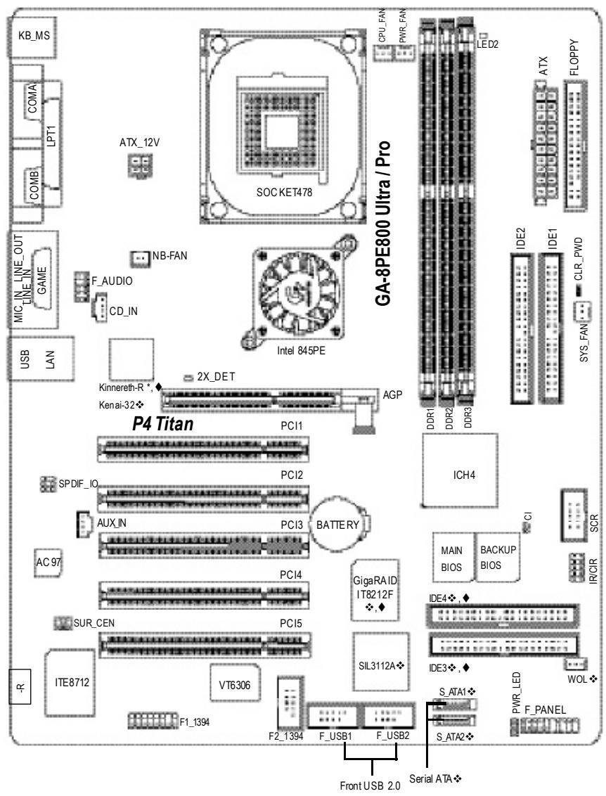
* For GA-8PE800 Pro Only ◆For GA-8PE800 Pro-R Only ◆For GA-8PE800 Ultra Only
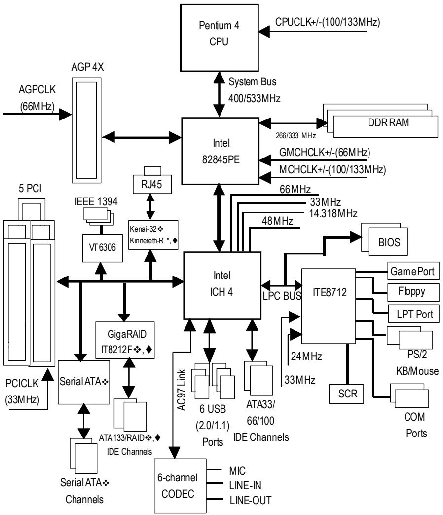
Block Diagram

* For GA-8PE800 Pro Only ◆For GA-8PE800 Pro-R Only ◆For GA-8PE800 Ultra Only
Chapter 2 Hardware Installation Process
To set up your computer, you must complete the following steps:
Step 1- Install the Central Processing Unit (CPU)
Step 2- Install memory modules
Step 3- Install expansion cards
Step 4- Connect ribbon cables, cabinet wires, and power supply

Congratulations you have accomplished the hardware installation!
Turn on the power supply or connect the power cable to the power outlet. Continue with the BIOS/software installation.
Step 1: Install the Central Processing Unit (CPU)
Before installing the processor, adhere to the following warning:

If you do not match the CPU socket Pin 1 and CPU cut edge well, it will cause improper installation. Please change the insert orientation.
Please make sure the CPU type is supported by the motherboard.
Step 1-1: CPU Installation

- Angling the rod to 65-degree maybe feel a kind of fright, and then continue pull the rod to 90-degree when a noise "cough" made.
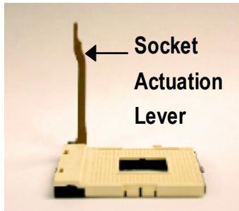
- Pull the rod to the 90-degree directly.
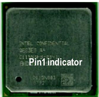
- CPU Top View
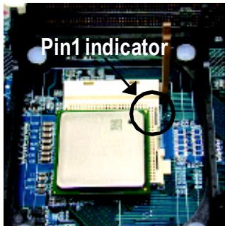
- Locate Pin 1 in the socket and look for a (golden) cutedge on the CPU upper corner. Then insert the CPU into the socket.
Step 1-2: CPU Heat Sink Installation

Before installing the CPU Heat Sink, adhere to the following warning:
- Please use Intel approved cooling fan.
2.We recommend you to apply the thermal tape to provide better heat conduction between your CPU and heatsink.
(The CPU cooling fan might stick to the CPU due to the hardening of the thermal paste. During this condition if you try to remove the cooling fan, you might pull the processor out of the CPU socket alone with the cooling fan, and might damage the processor. To avoid this from happening, we suggest you to either use thermal tape instead of thermal paste, or remove the cooling fan with extreme caution.)
3.Make sure the CPU fan power cable is plugged in to the CPU fan connector, this completes the installation.
Please refer to CPU heat sink user's manual for more detail installation procedure.
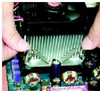
1. Fasten the heatsink supporting-base onto the CPU socket on the mainboard.
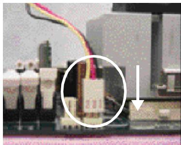
2. Make sure the CPU fan is plugged to the CPU fan connector, than install complete.
Step 2: Install memory modules

Before installing the processor and heatsink, adhere to the following warning: When DIMM LED is ON, do not install/remove DIMM from socket. Please note that the DIMM module can only fit in one direction due to the one notche Wrong orientation will cause improper installation. Please change the insert orientatio
The motherboard has 3 dual inline memory module (DIMM) sockets, but it can only support a maximum of 4 banks of DDR memory. DDR sockets 1 uses 2 banks, DDR sockets 2&3 share the remaining 2 banks. Please refer to the following tables for possible memory configurations supported. The BIOS will automatically detect memory type and size. To install the memory module, just push it vertically into the DIMM socket .The DIMM module can only fit in one direction due to the notch.
Memory size can vary between sockets.
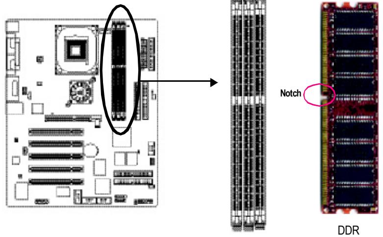
Support Unbuffered DDR DIMM Sizes type:
| 64 Mbit (2Mx8x4 banks) | 64 Mbit (1Mx16x4 banks) | 128 Mbit(4Mx8x4 banks) |
| 128 Mbit(2Mx16x4 banks) | 256 Mbit(8Mx8x4 banks) | 256 Mbit(4Mx16x4 banks) |
| 512 Mbit(16Mx8x4 banks) | 512 Mbit(8Mx16x4 banks) | |
| Total System Memory (Max2GB) | ||
| DDR1 | DDR2 | DDR3 |
| S | S | S |
| D | S | S |
| D | D | X |
| D | X | D |
| S | D | X |
| S | X | D |
D:Double Sided DIMM S:Single Sided DIMM X:Not Use
- The DIMM slot has a notch, so the DIMM memory module can only fit in one direction.
- Insert the DIMM memory module vertically into the DIMM slot. Then push it down.
- Close the plastic clip at both edges of the DIMM slots to lock the DIMM module. Reverse the installation steps when you wish to remove the DIMM module.
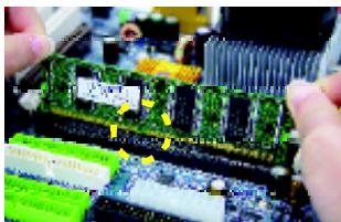
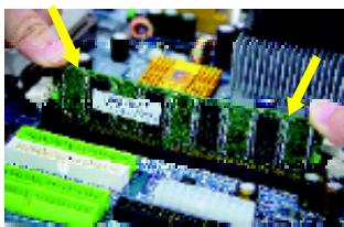
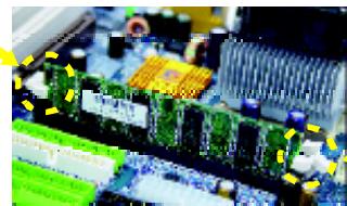
DDRIntroduction
Established on the existing SDRAM industry infrastructure, DDR (Double Data Rate) memory is a high performance and cost-effective solution that allows easy adoption for memory vendors, OEMs and system integrators.
DDR memory is a sensible evolutionary solution for the PC industry that builds on the existing SDRAM infrastructure, yet makes awesome advances in solving the system performance bottleneck by doubling the memory bandwidth. DDR SDRAM will offer a superior solution and migration path from existing SDRAM designs due to its availability, pricing and overall market support. PC2100 DDR memory (DDR266) doubles the data rate through reading and writing at both the rising and falling edge of the clock, achieving data bandwidth 2X greater than PC133 when running with the same DRAM clock frequency. With peak bandwidth of 2.664GB per second, DDR memory enables system OEMs to build high performance and low latency DRAM subsystems that are suitable for servers, workstations, high-end PC's and value desktop SMA systems. With a core voltage of only 2.5 Volts compared to conventional SDRAM's 3.3 volts, DDR memory is a compelling solution for small form factor desktops and notebook applications.
Step 3: Install expansion cards
- Read the related expansion card's instruction document before install the expansion card into the computer.
- Remove your computer's chassis cover, necessary screws and slot bracket from the computer.
- Press the expansion card firmly into expansion slot in motherboard.
- Be sure the metal contacts on the card are indeed seated in the slot.
- Replace the screw to secure the slot bracket of the expansion card.
- Replace your computer's chassis cover.
- Power on the computer, if necessary, setup BIOS utility of expansion card from BIOS.
- Install related driver from the operating system.

AGP Card
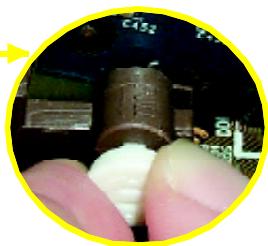
Please carefully pull out the small white- drawable bar at the end of the AGP slot when you try to install/ Uninstall the AGP card. Please align the AGP card to the onboard AGP slot and press firmly down on the slot. Make sure your AGP card is locked by the small white- drawable bar.

When an AGP 2x (3.3V) card is installed the 2X_DET will light up, indicating a non-supported graphics card is inserted. Informing users that system might not boot up normally due to AGP 2x (3.3V) is not supported by the chipset.
Step 4: Connect ribbon cables, cabinet wires, and power supply
Step 4-1: I/O Back Panel Introduction

PS/2 Keyboard and PS/2 Mouse Connector
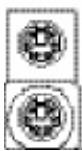
PS/2 Mouse Connector (6 pin Female)
PS/2 Keyboard Connector (6 pin Female)
This connector supports standard PS/2 keyboard and PS/2 mouse.
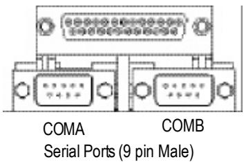
Parallel Port and Serial Ports (COMA/COMB)
Parallel Port (25 pin Female)
This connector supports 2 standard COM ports and 1 Parallel port. Device like printer can be connected to Parallel port; mouse and modem can be connected to Serial ports.
Game/MIDI Ports
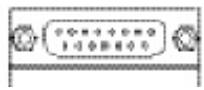
Joystick/ MIDI (15 pin Female)
This connector supports joystick, MIDl keyboard and other relate audio devices.
Audio Connectors
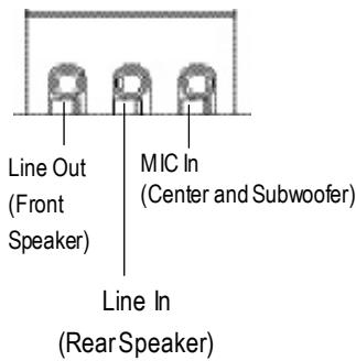
After install onboard audio driver, you may connect speaker to Line Out jack, micro phone to MIC In jack. Device like CD-ROM, walkman etc can be connected to Line-In jack.
Please note:
You are able to use 2-/4-/6- channel audio feature by S/W selection.
If you want to enable 6-channel function, you have 2 choose for hardware connection.
Method1:
Connect "Front Speaker" to "Line Out"
Connect "Rear Speaker" to "Line In"
Connect "Center and Subwoofer" to "MIC Out".
Method2:
You can refer to page 31, and contact your nearest dealer for optional SUR_CEN cable.

If you want the detail information for 2-/4-/6-channel audio setup installation, please refer to "2-/4-/6-Channel Audio Function Introduction".
USB/LAN Connector
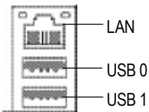
Before you connect your device(s) into USB connector(s), please make sure your device(s) such as USB keyboard, mouse, scanner, zip, speaker..etc. Have a standard USB interface. Also make sure your OS supports USB controller. If your OS does not support USB controller, please contact OS vendor for possible patch or driver upgrade. For more information please contact your OS or device(s) vendors.
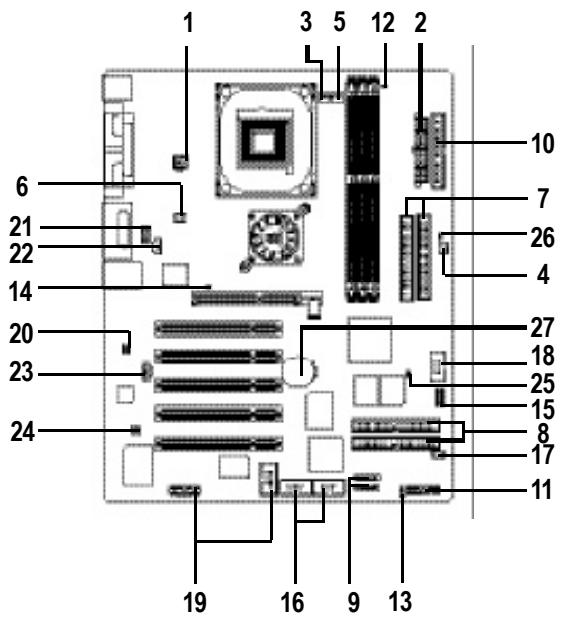
Step 4-2: Connectors & Jumper Setting Introduction
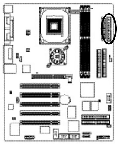
This connector (ATX_12V) supplies the CPU operation voltage (Vcore). If this "ATX_12V connector" is not connected, system cannot boot.
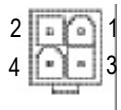
| PinNo. | Definition |
| 1 | GND |
| 2 | GND |
| 3 | +12V |
| 4 | +12V |
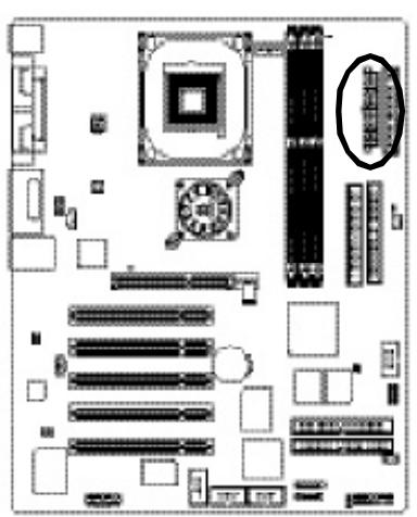
2)ATX_POWER(ATXPower)
AC power cord should only be connected to your power supply unit after ATX power cable and other related devices are firmly connected to the mainboard.
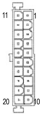
| Pin No. | Definition |
| 1 | 3.3V |
| 2 | 3.3V |
| 3 | GND |
| 4 | VCC |
| 5 | GND |
| 6 | VCC |
| 7 | GND |
| 8 | PowerGood |
| 9 | 5V SB(stand by +5V) |
| 10 | +12V |
| 11 | 3.3V |
| 12 | -12V |
| 13 | GND |
| 14 | PS_ON(softOn/Off) |
| 15 | GND |
| 16 | GND |
| 17 | GND |
| 18 | -5V |
| 19 | VCC |
| 20 | VCC |
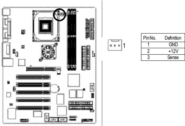
3) CPU_FAN (CPU FAN Connector)
Please note, a proper installation of the CPU cooler is essential to prevent the CPU from running under abnormal condition or damaged by overheating. The CPU fan connector supports Max. current up to 600 mA.
4) SYS_FAN(System FAN Connector)
This connector allows you to link with the cooling fan on the system case to lower the system temperature.
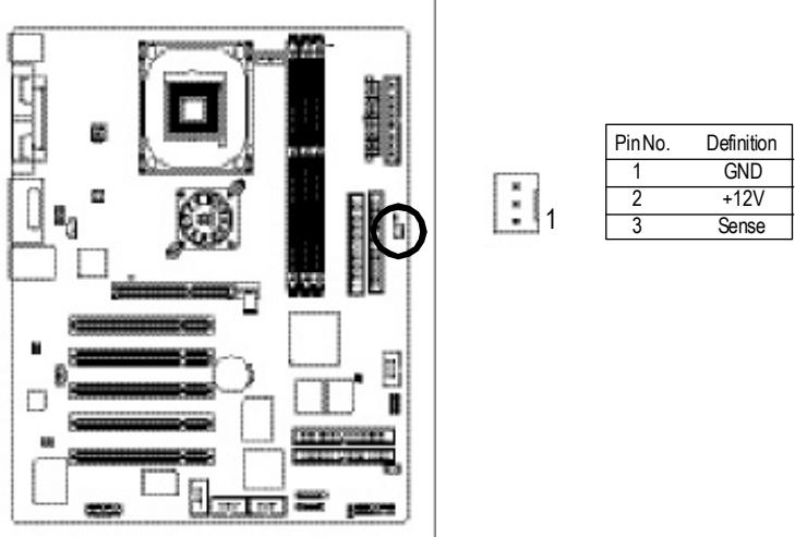
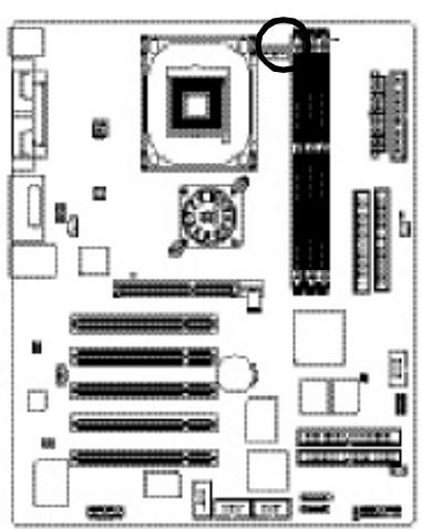
5) PWR_FAN (PowerFan Connector)
This connector allows you to link with the cooling fan on the system case to lower the system temperature.

| PinNo. | Definition |
| 1 | GND |
| 2 | +12V |
| 3 | Sense |
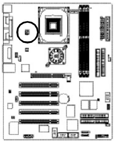
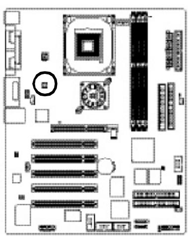
6) NB_FAN
If you installed wrong direction, the Chip Fan will not work. Sometimes will damage the Chip Fan. (Usually black cable is GND)

1
| PinNo. | Definition |
| 1 | VCC |
| 2 | GND |
7) IDE1/IDE2(IDE1/IDE2 Connector)
Please connect first hardisk to IDE1 and connect CDROM to IDE2. The red stripe of the ribbon cable must be the same side with the Pin1.

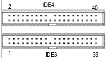
8) IDE3 /IDE4 (RAID/ATA133,Green Connectorr) 心 ,
The rad stripe of the ribbon cable must be the same side with the Pin1.
If you wish to use IDE3 and IDE4, please use it in unity with BIOS (either RAID or ATA133).
Then, install the correct driver to have proper operation. For details, please refer to the RAID manual.
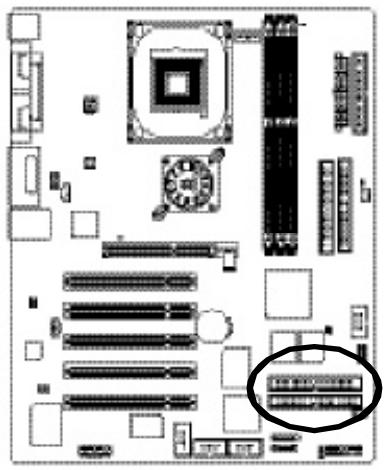
(BIOS Default Value :ATA, If you want to use RAID function, please change "Integrated Peripherals-RAID Controller Function " to "RAID")
- For GA-8PE800 Pro Only ◆For GA-8PE800 Pro-R Only ◆For GA-8PE800 Ultra Only
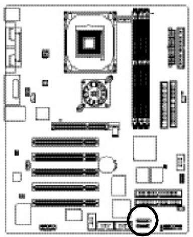
9) S_ATA1/S_ATA2 (SerialATAConnector)
You can connect the Serial ATA device to this connector, it provides you high speed transfer rates (150MB/sec).
1 7
| PinNo. | Definition |
| 1 | GND |
| 2 | TXP |
| 3 | TXN |
| 4 | GND |
| 5 | RXN |
| 6 | RXP |
| 7 | GND |
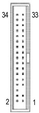
10)FDD (Floppy Connector)
Please connect the floppy drive ribbon cables to FDD. It supports 360K,720K,1.2M,1.44M and 2.88Mbytes floppy disk types. The red stripe of the ribbon cable must be the same side with the Pin1.
- For GA-8PE800 Pro Only ◆For GA-8PE800 Pro-R Only ◆For GA-8PE800 Ultra Only
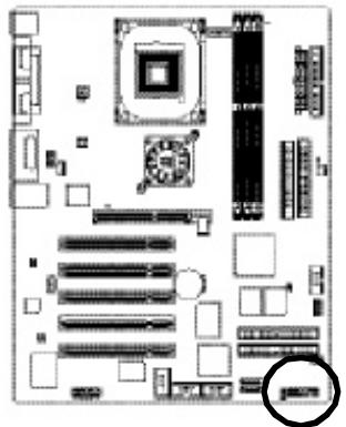
11) F PANEL (2x10 pins connector)
Please connect the power LED, PC peaker, reset switch and power switch etc. of your chassis frontpanel to the F PANEL connector according to the pin assignment above.
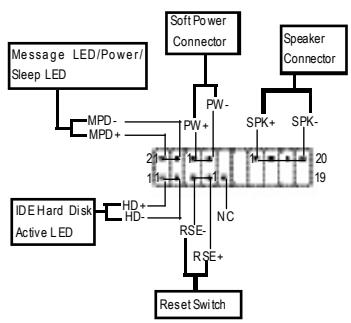
| HD (IDEHard DiskActive LED) (Blue) | Pin 1: LED anode(+) Pin2: LED cathode(-) |
| SPK(Speaker Connector) (Amber) | Pin 1: VCC(+) Pin 2: Pin 3: NC Pin 4: Data(-) |
| RES (Reset Switch) (Green) | Open: Normal Operation Close: Reset Hardware System |
| PW (Soft Power Connector) (Red) | Open: Normal Operation Close: Power On/Off |
| MSG (Message LED/Power/ SleepLED)(Yellow) | Pin 1: LED anode(+) Pin2: LED cathode(-) |
| NC (Purple) | NC |
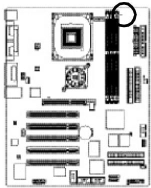
12) LED2
Do not remove memory modules while DIMM LED is on. It might cause short or other unexpected damages due to the 2.5V stand by voltage. Remove memory modules only when AC Power cord is disconnected.

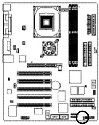
13)PWR_LED
PWR_LED is connect with the system power indicator to indicate whether the system is on/off. It will blink when the system enters suspend mode. If you use dual color LED, power LED will turn to another color.
1
| PinNo. | Definition |
| 1 | MPD+ |
| 2 | MPD- |
| 3 | MPD- |
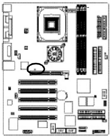
14)2X_DET
When an AGP 2X (3.3V) card is installed the 2X_DET will light up, indicating a nonsupported graphics card is inserted. Informing users that system might not boot up normally due to AGP 2X (3.3V) is not supported by the chipset.

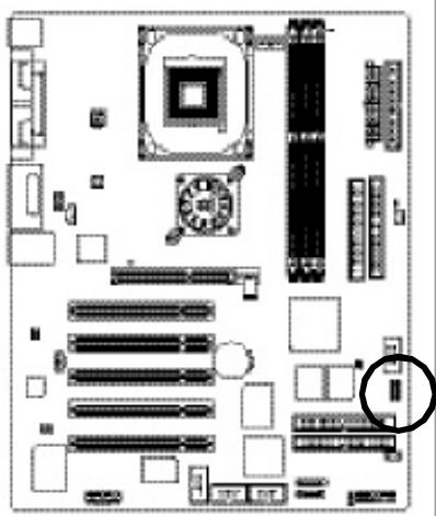
15)IR_CIR
Make sure the pin 1 on the IR device is aling with pin one the connector. To enable the IR/CIR function on the board, you are required to purchase an option IR/CIR module. For detail information please contact your authorized Giga-Byte distributor.
To use IR function only, please connect IR module to Pin1 to Pin5.

| PinNo. | Definition |
| 1 | VCC |
| 2 | NC |
| 3 | IRRX |
| 4 | GND |
| 5 | IRTX |
| 6 | NC |
| 7 | CIRRX |
| 8 | VCC |
| 9 | CIRTX |
| 10 | NC |
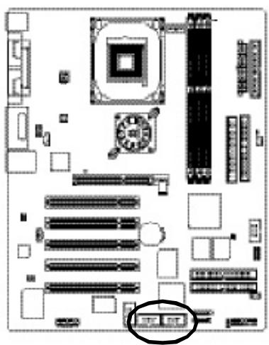
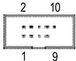
16)F_USB1/F_USB2(Front USB Connector, Yellow)
Be careful with the polarity of the front USB connector. Check the pin assignment while you connect the front USB cable. Please contact your nearest dealer for optional front USB cable.
| PinNo. | Definition |
| 1 | Power |
| 2 | Power |
| 3 | USBDX- |
| 4 | USBDy- |
| 5 | USBDX+ |
| 6 | USBDy+ |
| 7 | GND |
| 8 | GND |
| 9 | NoPin |
| 10 | NC |
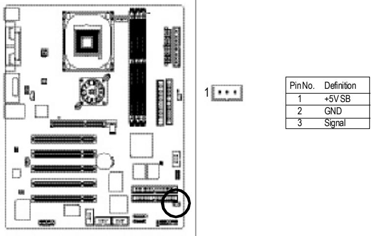
17)WOL (Wake On Lan)
This connector allows the remove servers to manage the system that installed this mainboard via your network adapter which also supports WOL.
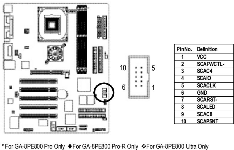
18)SCR (Smart Card Reader Header,Black Connector)
This MB supports smart card reader. To enable smart card reader function an optional smart card reader box is required. Please contact your authorized distributor.
19) F1_1394/F2_1394 (IEEE 1394 Connector)
Please Note: Serial interface standard set by Institute of Electrical and Electronics Engineers, which has features like high speed, high bandwidth and hot plug.
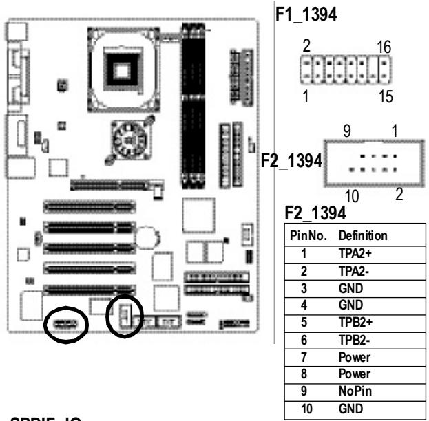
F1_1394
| PinNo. | Definition |
| 1 | Power |
| 2 | Power |
| 3 | TPA0+ |
| 4 | TPA0- |
| 5 | GND |
| 6 | GND |
| 7 | TPB0+ |
| 8 | TPB0- |
| 9 | Power |
| 10 | Power |
| 11 | TPA1+ |
| 12 | TPA1- |
| 13 | GND |
| 14 | NoPin |
| 15 | TPB1+ |
| 16 | TPB1- |
20) SPDIF_IO
The SPDIF output is capable of providing digital audio to external speakers or compressed AC3 data to an external Dolby Digital Decoder. Use this feature only when your stereo system has digital input function.
Use SPDF IN feature only when your device has digital output function.
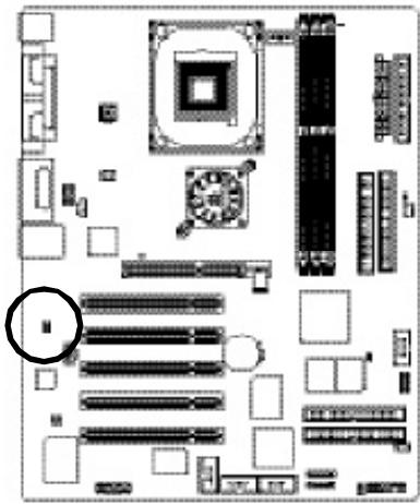

| PinNo. | Definition |
| 1 | VCC |
| 2 | NoPin |
| 3 | SPDIF |
| 4 | SPDIFI |
| 5 | GND |
| 6 | GND |
If you want to use FrontAudio connector, you must remove 5-6, 9-10 Jumper. In order to utilize the frontaudio header, your chassis must have front audio connector. Also please make sure the pin assignment on the cable is the same as the pin assignment on the MB header. To find out if the chassis you are buying support frontaudio connector, please contact your dealer.
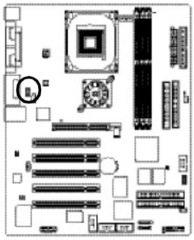

| PinNo. | Definition |
| 1 | MIC |
| 2 | GND |
| 3 | REF |
| 4 | POWER |
| 5 | FrontAudio(R) |
| 6 | RearAudio(R) |
| 7 | Reserved |
| 8 | NoPin |
| 9 | FrontAudio(L) |
| 10 | RearAudio(L) |
Connect CD-ROM or DVD-ROM audio out to the connector.
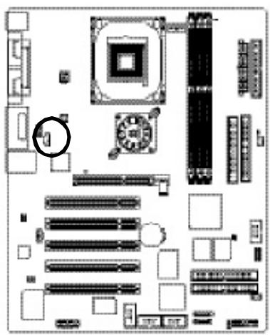
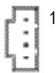
| PinNo. | Definition |
| 1 | CD-L |
| 2 | GND |
| 3 | GND |
| 4 | CD-R |
23) AUX_IN (AUX In Connector)
Connect other device(such as PCI TV Tunner audio out) to the connector.
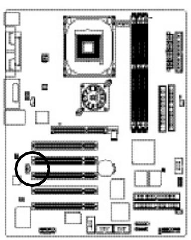
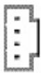
1
| PinNo. | Definition |
| 1 | AUX-L |
| 2 | GND |
| 3 | GND |
| 4 | AUX_R |
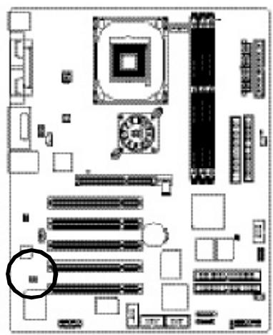
24) SUR_CEN
Please contact your nearest dealer for optional SUR_CEN cable.
| PinNo. | Definition |
| 1 | SUROUTL |
| 2 | SUROUTR |
| 3 | GND |
| 4 | NoPin |
| 5 | CENTER_OUT |
| 6 | BASS_OUT |
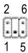
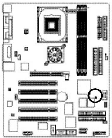
25) CI (CASE OPEN)
This 2 pin connector allows your system to enable or disable the "case open" item in BIOS if the system case begins to be enabled.
81
| PinNo. | Definition |
| 1 | Signal |
| 2 | GND |
26) CLR_PWD
When Jumper is set to "open" and system is restarted, the password that is set will be cleared.
On the contrary when Jumper is set to "close", the current status remains
PS, the function offers a solution for users who forget the password.
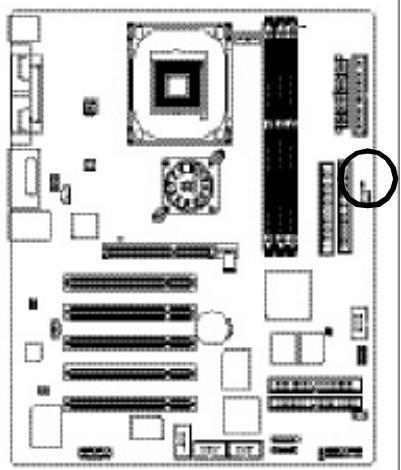

open: Clear password

close: Normal
27) BATTERY(Battery)
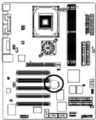
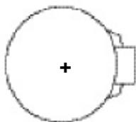
CAUTION
Danger of explosion if battery is incorrectly replaced.
Replace only with the same or equivalent type recommended by the manufacturer.
- Dispose of used batteries according to the manufacturer's instructions.
If you want to erase CMOS...
- Turn OFF the computer and unplug the power cord.
2.Remove the battery, wait for 30 second.
3.Re-install the battery.
4.Plug the power cord and turn ON the computer.
Chapter 3 BIOS Setup
BIOS Setup is an overview of the BIOS Setup Program. The program that allows users to modify the basic system configuration. This type of information is stored in battery-backed CMOS RAM so that it retains the Setup information when the power is turned off.
ENTERING SETUP
After power on the computer, pressing immediately during POST (Power On Self Test) it will allow you to enter standard BIOS CMOS SETUP.
If you require more advanced BIOS settings, please go to "advanced BIOS" setting menu. To enter Advanced BIOS setting menu, press "Ctrl+F1" key on the BIOS screen.
CONTROL KEYS
| <个> | Move to previous item |
| <↓> | Move to next item |
| <←> | Move to the item in the left hand |
| <→> | Move to the item in the right hand |
| <Esc> | Main Menu - Quit and not save changes into CMOS Status Page Setup Menu and Option Page Setup Menu - Exit current page and return to Main Menu |
| <+/PgUp> | Increase the numeric value or make changes |
| </PgDn> | Decrease the numeric value or make changes |
| <F1> | General help, only for Status Page Setup Menu and Option Page Setup Menu |
| <F2> | Item help |
| <F3> | Reserved |
| <F4> | Reserved |
| <F5> | Restore the previous CMOS value from CMOS, only for Option Page Setup Menu |
| <F6> | Load the default CMOS value from BIOS default table, only for Option Page Setup Menu |
| <F7> | Load the Setup Defaults |
| <F8> | Dual BIOS/Q-Flash |
| <F9> | Reserved |
| <F10> | Save all the CMOS changes, only for Main Menu |
GETTING HELP
Main Menu
The on-line description of the highlighted setup function is displayed at the bottom of the screen.
Status Page SetupMenu / Option Page Setup Menu
Press F1 to pop up a small help window that describes the appropriate keys to use and the possible selections for the highlighted item. To exit the Help Window press
The Main Menu (For example: BIOS Ver. : F1)
Once you enter Award BIOS CMOS Setup Utility, the Main Menu (Figure 1) will appear on the screen. The Main Menu allows you to select from eight setup functions and two exit choices. Use arrow keys to select among the items and press
CMOS Setup Utility -Copy right (C) 1984-2003 Award Software
| Standard CMOS Features | SelectLanguage |
| Advanced BIOS Features | Load Fail-Safe Defaults |
| Integrated Peripherals | Load Optimized Defaults |
| Power Management Setup | SetSupervisor Password |
| PnP/PCI Configurations | SetUserPassword |
| PC Health Status | Save & ExitSetup |
| Frequency/Voltage Control | ExitWithout Saving |
| Top Performance | |
| ESC:Quit | F3:ChangeLanguage |
| F8:Dual BIOS /Q-Flash | F10:Save & Exit Setup |
| Time, Date, Hard Disk Type... | |

Figure 1:MainMenu
If you can't find the setting you want, please press "Ctrl+F1" to search the advanced option widden.
Standard CMOS Features
This setup page includes all the items in standard compatible BIOS.
AdvancedBIOSFeatures
This setup page includes all the items of Award special enhanced features.
- Integrated Peripherals
This setup page includes all onboard peripherals.
Power Management Setup
This setup page includes all the items of Green function features.
PnP/PCI Configurations
This setup page includes all the configurations of PCI & PnP ISA resources.
PC Health Status
This setup page is the System auto detect Temperature, voltage, fan, speed.
Frequency/Voltage Control
This setup page is control CPU's clock and frequency ratio.
Top Performance
Top Performance Defaults indicates the value of the system parameters which the system would be in best performance configuration.
- Select Language
This setup page is select multi language.
- Load Fail-Safe Defaults
Fail-Safe Defaults indicates the value of the system parameters which the system would be in safe configuration.
- Load Optimized Defaults
Optimized Defaults indicates the value of the system parameters which the system would be in better performance configuration.
Set Supervisor or password
Change, set, or disable password. It allows you to limit access to the system and Setup, or just to Setup.
Set User password
Change, set, or disable password. It allows you to limit access to the system.
Save & Exit Setup
Save CMOS value settings to CMOS and exit setup.
- Exit Without Saving
Abandon all CMOS value changes and exit setup.
Standard CMOS Features
CMOS Setup Utility -Copy right (C) 1984-2003 Award Software
Standard CMOS Features
Figure 2: Standard CMOS Features
| Date (mm:dd:yy) | Thu, Feb 21 2002 | Item Help |
| Time (hh:mm:ss) | 22:31:24 | Menu Level ▷ Change the day, month, year |
| IDE Primary Master | [Press Enter None] | |
| IDE Primary Slave | [Press Enter None] | |
| IDE Secondary Master | [Press Enter None] | |
| IDE Secondary Slave | [Press Enter None] | |
| Drive A | [1.44M, 3.5"] | |
| Drive B | [None] | 1 to 31(or max imun allow ed in the month.) |
| Floppy 3 Mode Support | [Disabled] | |
| Halt On | [All,But Keyboard] | 1999 to 2098 |
| BaseMemory | 640K | |
| ExtendedMemory | 130048K | |
| Total Memory | 131072K | |
| ↑↓→←: Move Enter:Select +/-/PU/PD:Value F10:Save ESC:Exit F1:General Help | ||
| F3:Language F5:Previous Values F6:Fail-Safe Defaults F7:Optimized Defaults | ||
Date
The date format is <week> , <month> , <day> , <year> .
Week The week, from Sun to Sat, determined by the BIOS and is display only
Month The month, Jan. Through Dec.
Day The day, from 1 to 31 (or the maximum allowed in the month)
Year Theyear,from1999through2098
Time
The times format in
IDE Primary Master, Slave / Secondary Master, Slave
The category identifies the types of hard disk from drive C to F that has been installed in the computer. There are two types: autotype, and manual type. Manual type is user-definable; Auto type which will automatically detect HDD type.
Note that the specifications of our drive must match with the drive table. The hard disk will not work properly if you enter improper information for this category.
If you select User Type, related information will be asked to enter to the following items. Enter the information directly from the keyboard and press
Capacity: The hard disk size. The unit is Mega Bytes.
AccessMode: Theoptions are: Auto/ Large/LBA/Normal.
Cylinder: The cylinder number of hard disk.
Head Theread/Writeheadnumberofhard disk.
Precomp The cylrinerumber atwhich the disk driver changes the writecurrent.
Landing Zone The cylinder number that the disk driver heads (read/write) are seated when the disk drive is parked.
SECTORS The sector number of each track define on the hard disk.
If a hard disk has not been installed select NONE and press
Drive A/Drive B
The category identifies the types of floppy disk drive A or drive B that has been installed in the computer.
None No floppy drive installed
360K, 5.25". 5.25 inch PC-type standard drive; 360K byte capacity.
1.2M, 5.25". 5.25 inch AT-type high-density drive; 1.2M byte capacity (3.5inch when 3 Mode is Enabled).
720K, 3.5". 3.5 inch double-sided drive; 720K by te capacity
1.44M, 3.5". 3.5 inch double-sided drive; 1.44M by te capacity.
2.88M,3.5 3.5inch double-sided drive; 2.88M by te capacity.
Floppy 3 Mode Support (for Japan Area)
Disabled Normal Floppy Drive. (Default value)
▶DriveA Enabled 3 mode function of Drive A.
▶Drive B Enabled 3 mode function of Drive B.
Both Drive A& Bare 3 mode Floppy Drives.
Halt on
The category determines whether the computer will stop if an error is detected during power up.
NOErrors The sy stem bootwill not stop for any error that may be detected and you will be prompted.
All Errors Whenever the BIOS detects a non-fatal error the system will be stopped.
All, But Keyboard The sy stem boot will not stop for a key board error; itw ill stop for all other errors. (Defaultvalue)
All, ButDiskette Thesystem bootwill not stop for a disk error; it will stop for all other errors.
All, ButDisk/Key The system boot will not stop for a keyboard or disk error; it will stop for all other errors.
Memory
The category is display-only which is determined by POST (Power On Self Test) of the BIOS.
Base Memory
The POST of the BIOS will determine the amount of base (or conventional) memory installed in the system.
The value of the base memory is typically 512 K for systems with 512 K memory installed on the motherboard, or 640 K for systems with 640 K or more memory installed on the motherboard.
Extended Memory
The BIOS determines how much extended memory is present during the POST.
This is the amount of memory located above 1 MB in the CPU's memory address map.
Advanced BIOS Features
CMOS Setup Utility -Copy right (C) 1984-2003 Award Software
Advanced BIOS Features
Figure 3: Advanced BIOS Features
| SATA/RAID / SCSI BootOrder\(\Leftrightarrow\),\(\Leftrightarrow\) | [SCSI] | Item Help |
| First Boot Device | [Floppy] | Menu Level ▲ |
| Second Boot Device | [HDD-0] | Selectionboard RAID |
| Third Boot Device | [CDROM] | or PCI SCSI boot rom |
| Boot Up Floppy Seek | [Disabled] | |
| PasswordCheck | [Setup] | |
| #CPUHyper-Threading | [Enabled] | |
| InitDisplay First | [AGP] | |
| \(↑↓→←: Move Enter;Select+/-/PU/PD;Value F10;Save ESC;Exit F1:General HelpF3:Language F5:Previous Values F6:Fail-Safe Defaults F7:Optimized Defaults\) | ||
" # " System will detect automatically and show up when you install the Intel®
Pentium® 4 processor with HT Technology.
SATA /RAID / SCSI Boot Order ,
This feature allows you to select the boot order SATA or RAID or SCSI device.
▶SATA Select your boot device priority by SATA.
RAID Select your boot device priority by RAID.
SCSI Select your boot device priority by SCSI.
First/Second/Third Boot device
This feature allows you to select the boot device priority.
Floppy Selecty our boot device priority by Floppy.
LS120 Select your boot device priority by LS120.
HDD-0-3 Select your bootdevice priority by HDD-0~3.
SCSI Select your boot device priority by SCSI.
CDROM Select your boot device priority by CDROM.
LAN Select your boot device priority by LAN.
USB-CDROM Select your boot device priority by USB-CDROM.
- For GA-8PE800 Pro Only ◆ForGA-8PE800 Pro-R Only ◆ForGA-8PE800 Ultra Only
USB-ZIP Select your boot device priority by USB-ZIP.
USB-FDD Select your boot device priority by USB-FDD.
USB-HDD Select your boot device priority by USB-HDD.
ZIP Select your boot device priority by ZIP.
Disabled Disabled this function.
Boot Up Floppy Seek
During POST, BIOS will determine the floppy disk drive installed is 40 or 80 tracks. 360 K type is 40 tracks 720 K, 1.2 M and 1.44 M are all 80 tracks.
▶ Enabled BIOS searches for floppy disk drive to determine it is 40 or 80 tracks. Note that BIOS can not tell from 720 K, 1.2 M or 1.44 M drive type as they are all80tracks.
Disabled BIOS will notsearch for the type of floppy disk drive by track number. Note that there will not be any warning message if the drive installed is 360 K. (Default value)
Password Check
System The system can not boot and can not access to Setup page will be denied if the correct password is not entered atthe prompt.
Setup The system will boot, but access to Setup will be denied if the correct password is not entered at the prompt. (Default value)
Hyper-Handling
▶ Enabled Enables CPU Hyper Threading Feature. Please note that this feature is only working for operating system with multi processors mode supported. (Default value)
Disabled Disables CPU Hyper Threading.
InitDisplayFirst
This feature allows you to select the first initiation of the monitor display from which card, when you install an AGP VGA card and a PCI VGA card on board.
PCI Sethit Display First to PCI Slot.
AGP Set hit Display First to AGP. (Default value)
Integrated Peripherals
CMOS Setup Utility -Copy right (C) 1984-2003 Award Software
Integrated Peripherals
Figure 4: Integrated Peripherals
| On-Chip Primary PCIIDE | [Enabled] | ItemHelp |
| On-Chip Secondary PCI IDE | [Enabled] | Manus |
| IDE1 Conductor Cable | [Auto] | If a hard disk controller Card isused, set at |
| IDE2 Conductor Cable | [Auto] | |
| USB Controller | [Enabled] | |
| USB Key board Support | [Disabled] | Disabled. |
| USB Mouse Support | [Disabled] | [Enable] |
| AC97 Audio | [Auto] | Enable onboard IDE |
| Onboard H/W SATA | [Enabled] | PORT |
| Serial ATA Function | [RAID] | [Disable] |
| Onboard H/W 1394 | [Enabled] | Disabled onboard IDE |
| Onboard H/W RAID | [Enabled] | PORT. |
| Onboard H/W LAN | [Enabled] | |
| Onboard LAN Boot ROM | [Disabled] | |
| Onboard Serial Port 1 | [3F8/IRQ4] | |
| Onboard Serial Port 2 | [2F8/IRQ3] | |
| UARTMode Select | [Normal] | |
| ×UR2Duplex Mode | Half | |
| Onboard Parallel Port | [378/IRQ7] | |
| ParallelPort Mode | [SPP] | |
| ×ECP Mode Use DMA | 3 | |
| Game Port Address | [201] | |
| Mdi Port Address | [Disabled] | |
| Midi Port IRQ | [10] | |
| CIR Port Address | [Disabled] | |
| ×CIR Port IRQ | 11 | |
| ↑↓→←: Move Enter;Select +/-/PU/PD;Value F10: Save ESC;Exit F1: General Help | ||
| F3:Language F5:Previous Values F6:Fail-Safe Defaults F7:Optimized Defaults | ||
- For GA-8PE800 Pro Only ◆For GA-8PE800 Pro-R Only ◆ForGA-8PE800 Ultra Only
On-Chip Primary PCI IDE
- When enabled, allows you to use the onboard primary PCI IDE. If a hard disk controller card is used, set at Disabled.
Enabled Enable onboard 1st channel IDE port (Default value)
Disabled Disable onboard 1st channel IDE port.
On-Chip Secondary PCI IDE
- When enabled, allows you to use the onboard secondary PCI IDE. If a hard disk controller card is used, set at Disabled.
Enabled Enable onboard 2nd channel IDE port (Default value)
Disabled Disable onboard 2nd channel IDE port.
IDE1 Conductor Cable
Auto Will be automatically detected by BIOS(DefaultValue)
ATA66/100 SetIDE1 Conductor Cable to ATA66/100 (Please make sure your IDE device and cable is compatible with ATA66/100)
ATA33 SetIDE1 Conductor Cable to ATA33 (Please make sure your IDE device and cable is compatible with ATA33)
IDE2 Conductor Cable
Auto Will be automatically detected by BIOS(DefaultValue)
ATA66/100 SetIDE2 Conductor Cable to ATA66/100 (Please make sure your IDE device and cable is compatible with ATA66/100)
ATA33 SetIDE2 Conductor Cable to ATA33 (Please make sure your IDE device and cable is compatible with ATA33).
USB Controller
Disable this option if you are not using the onboard USB feature.
Enabled Enabled USB Controller. (Default value)
Disabled Disabled USB Controller.
USB Keyboard Support
- When a USB key board is installed, please set at Enabled.
Enabled Enabled USB Key board Support.
Disabled Disabled USB Keyboard Support. (Default value)
US B Mouse Support
Enabled Enabled USB Mouse Support.
Disabled Disabled USB Mouse Support. (Default value)
AC97 Audio
Auto BIOSwill automatically detect onboard AC97 Audio. (Default value)
Disabled Disabled AC97 Audio.
Onboard H/W SATA
Disable this option if you are not using the onboard Serial ATA feature.
Enabled Enabled Onboard H/W Serial ATA support(Defaultvalue)
Disabled Disabled Onboard H/WSerial ATA.
Serial ATA Function
RAID Select onboard Serial ATA chip function as RAID.(Default value)
BASE Select onboard Serial ATA chip function as BASE.
Onboard H/W 1394
Enable Enabledonboard IEEE 1394 function.(Defaultvalue)
Disable Disabled this function.
Onboard H/W RAID, (For IDE3/4)
If you don't set any HDDDevice in IDE3 or 4 but enable the function, thenormal message
"MBUltra133 BIOSis not installedbecause there are no drivesattached" will come out.
Ignore this message or set the option disable to make the message disappear.
Enable Enabled onboard ATA/RAID function. (Default value)
Disable Disabled this function.
Onboard H/W LAN
Enable Enabled onboard LAN function.(Default value)
Disable Disable onboard LAN function.
- For GA-8PE800 Pro Only ◆For GA-8PE800 Pro-R Only ◆ForGA-8PE800 Ultra Only
Onboard LAN Boot ROM
The function is to invoke onboard LAN chip to boot up the system
Enable Enable onboard LAN boot ROM function.
Disable Disable this function. (Defaultvalue)
Onboard Serial Port 1
Auto BIOSwill automatically setup the port 1 address.
3F8 / IRQ4 Enable onboard Serial port 1 and address is 3F8. (Default value)
2F8 / IRQ3 Enable onboard Serial port 1 and address is 2F8.
3E8 / IRQ4 Enable onboard Serial port 1 and address is 3E8.
2E8 / IRQ3 Enable onboard Serial port 1 and address is 2E8.
Disabled Disable onboard Serial port 1.
Onboard Serial Port 2
Auto BIOSwill automatically setup the port 2 address.
3F8 / IRQ4 Enable onboard Serial port 2 and address is 3F8.
2F8 / IRQ3 Enable onboard Serial port 2 and address is 2F8. (Default Value)
3E8 / IRQ4 Enable onboard Serial port 2 and address is 3E8.
2E8 / IRQ3 Enable onboard Serial port 2 and address is 2E8.
Disabled Disable onboard Serial port 2.
UART Mode Select
This feature allows you to determine which Infra Red(R) function of Onboard I/O chip
ASKIR Using as IR and set to ASKIR Mode.
IrDA Using as R and set toIrDA Mode.
Normal Usingas standard serial port. (Default Value)
SCR Using as smart card Interface.
UR2Duplex Mode(When UART Mode Select isset [ASKIR or IrDA or SCR])
- This feature allows you to select the R modes.
Half IR Function Duplex Half. (Default Value)
Full IR FunctionDuplex Full.
OnBoard Parallel port
This feature allows you to select from a given set of parameters if the parallel port uses the onboard I/O controller.
378/IRQ7 Enable On Board LPT port and address is 378.(Default Value)
278 / IRQ5 Enable On Board LPT port and address is 278.
3BC / IRQ7 Enable On Board LPT port and address is 3BC.
Parallel Port Mode
This feature allows you to connect with an advanced print via the port mode it supports.
SPP Using Parallel port as Standard Parallel Port. (Default Value)
EPP Using Parallel portas Enhanced Parallel Port.
ECP Using Parallel port as Extended Capabilities Port.
ECP+EPP Using Parallel port as ECP & EPP mode.
ECP Mode Use DMA(When Parallel Port Mode is set [ECPorECP+EPP])
3 Use DMA 3 for ECP mode. (Default value)
1 Use DMA 1 for ECP mode.
Game Port Address
Disabled Disabled this function.
▶201 Enabled Game Port and Address is 201. (Default Value)
▶209 Enabled Game Portand Address is 209.
Midi Port Address
Disabled Disabled this function. (Default Value)
300 Enabled Mid Portand Address is 300.
330 Enabled Midi Portand Address is 330.
Midi Port IRQ
5 MidiPortuseRQ5.
10 Midi Portuse IRQ 10. (Default Value)
CIR Port Address
This feature allows you to select CR portaddress or disable it.
Disabled
Disabled this function. (Default Value)
310
Enabled CIR and Address is 310.
320
Enabled CIR and Address is 320.
CIR Port IRQ (When Parallel Port Mode is set [ECP or ECP+EPP])
This feature allows you to select CIR IRQ, if CIR is enabled.
5
CIR use IRQ 5.
11
CRuseRQ11(Default Value)
Power Management Setup
CMOS Setup Utility -Copy right (C) 1984-2003 Award Software
Power Management Setup
Figure 5: Power Management Setup
| ACPI Suspend Type | [S1(POS)] | Item Help |
| Power LED in S1 State | [Blinking] | Menu Level ▲ |
| SoftOff by PWR-BTTN | [Instant-off] | [S1] |
| PME Event Wake Up | [Enabled] | SetSuspend Type to Power On |
| ModemRingOn/WakeOnLAN | [Enabled] | Suspend under ACPIOS |
| Resumeby Alarm | [Disabled] | |
| × Date(of Month) Alarm | Everyday | [S3] |
| × Time(hh:mm:ss) Alarm | 0:0:0 | for ACPIOS |
| Power On By Mouse | [Disabled] | SetSuspend Type to Suspend to RAM under ACPIOS |
| Power OnBy Key board | [Disabled] | |
| × KB Power On Password | Enter | |
| AC Back Function | [Soft-Off] | |
| ↑↓→←: Move Enter:Select+/-/PU/PD:Value F10:Save ESC:Exit F1:General HelpF3:Language F5:Previous Values F6:Fail-Safe Defaults F7:Optimized Defaults | ||
ACPI Suspend Type
S1(POS) SetACPI Suspend Type to S1/POS (Power OnSuspend). (Default value)
S3(STR) SetACPISuspend Type to S3/STR (Suspend To RAM).
Power LED in S1 State
Blinking In standby mode(S1), power LED will blink. (Default Value)
Dual/Off In standby mode(S1):
a. If use single color LED, power LED will turn off.
b. If use dual color LED, power LED will turn to another color.
Soft-off by PWR-BTNT
Instant-off Press power button then Power off instantly. (Default value)
Delay 4 Sec. Press power button 4 sec to Power of. Enter suspend if button is pressed less than 4 sec.
PME Event Wake up
When set at Enabled, any PCI-PM event awakes the system from a PCI-PM controlled state.
This feature requires anATX power supply that provides at least 1A on the +5VSB lead.
Disabled Disabled PME EventWake up function.
▶Enabled Enabled PME Event Wake up function. (DefaultValue)
ModemRing On/WakeOnLAN(WhenAC Back Function is set to [Soft-Off])
You can enable wake on LAN feature by the "ModemRingOn/WakeOnLAN" or "PME Event Wake up" when the M/B has "WOL" onboard connector. Only enabled the feature by "PME EventWake up".
An incoming call via modem awakes the system from its soft-off mode.
When set atEnabled, an input signal comes from the other client/server on the LAN awaks the system from a softoff state if connected over LAN.
Disabled Disabled Modem Ring On / Wake On LAN function.
Enabled Enabled Modem Ring On/Wake On LAN function. (Default Value)
Resume by Alarm
You can set "Resume by Alarm"item to enabled and key in Data/time to power on system.
Disabled Disable this function. (Default Value)
Enabled Enable alarm function to POWER ON system.
IfRTC Alarm Lead ToPowerOn is Enabled.
Date(ofMonth)Alarm: Everyday,1-31
Time (hh:mm:ss)Alam : (0 23):(0 59):(0 59)
Power On By Mouse
Disabled Disabled this function. (Defaultvalue)
MouseClick Setmouse doubleclick to power onsystem.
Power On By Keyboard
This feature allows you to set the method for powering-on the system.
The option "Password" allows you to set up to 5 alphanumeric characters to power-on the system.
The option "Keyboard 98" allows you to use the standard keyboard 98 to power on the system.
Password Enable K/B password function.
Disabled Disabled this function. (Defaultvalue)
Key board 98 Ify our keyboard have "POWER Key" button, you can press the key to power on any system.
KB Power ON Password
▶Enter Input password (from 1 to 5 characters) and press Enter to set the Key board Power On Password.
AC Back Function
Memory System power on depends on the status before AC lost.
Soft-Off Always in Offstate when AC back. (Default value)
Full-On Always power on the system when AC back.
PnP/PCI Configurations
CMOS Setup Utility -Copy right (C) 1984-2003 Award Software
PnP/PCI Configurations
Figure 6: PnP/PCI Configurations
| PCI1/PCI5 IRQ Assignment | [Auto] | Item Help |
| PCI2 IRQ Assignment | [Auto] | Menu Level ▶ |
| PCI3IRQ Assignment | [Auto] | Device(s)using this INT: |
| PCI4IRQ Assignment | [Auto] | RAID Cntrl -Bus 2 Dev 12 Func 0 USB 1.1 Host Cntrl -Bus 0 Dev 29 Func 2 |
| ↑↓→←: Move Enter:Select+/-/PU/PD:Value F10:Save ESC:Exit F1:General Help F3:Language F5:Previous Values F6:Fail-Safe Defaults F7:Optimized Defaults | ||
PC11/PC15 IRQ Assignment
Auto
Auto assign IRQ to PCI 1/PCI 5. (Default value)
3,4,5,7,9,10,11,12,15
Set3,4,5,7,9,10,11,12,15 to PC11/PC15.
PCI2 IRQ Assignment
Auto
Auto assign IRQ to PCI 2. (Default value)
3,4,5,7,9,10,11,12,15
Set3,4,5,7,9,10,11,12,15 to PCI2.
PCI3 IRQ Assignment
Auto
Auto assign IRQ to PCI 3. (Default value)
3,4,5,7,9,10,11,12,15
Set3,4,5,7,9,10,11,12,15 to PCI3.
PCI4 IRQ Assignment
Auto
Auto assign IRQ to PCI 4. (Default value)
3,4,5,7,9,10,11,12,15
Set3,4,5,7,9,10,11,12,15 to PCI4.
PC Health Status
CMOS Setup Utility -Copy right (C) 1984-2003 Award Software
PC Health Status
Figure7: PC Health Status
| Reset Case Open Status | [Disabled] | Item Help |
| CaseOpened | No | MenuLevel▶ |
| VCORE | 1.448V | [Disabled] |
| +1.5V | 1.448V | Do'nt reset case |
| +3.3V | 3.312V | open status |
| +5V | 5.080 V | [Enabled] |
| +12V | 11.904V | Clear Case open |
| Current CPU Temperature | 30°C | status at next boot. |
| Current CPU FAN Speed | 4440 RPM | |
| Current POWER FAN speed | 0 RPM | |
| Current SYSTEM FAN speed | 0 RPM | |
| CPU Warning Temperature | [Disabled] | |
| CPU FAN Fail Waming | [Disabled] | |
| POWER FAN Fail Waming | [Disabled] | |
| SYSTEM FAN Fail Warning | [Disabled] | |
| ↑↓→←: Move Enter. Select +/-/PU/PD: Value F10: Save ESC: Exit F1: General HelpF3: Language F5: Previous Values F6: Fail-Safe Defaults F7: Optimized Defaults | ||
Reset Case Open Status
Case Opened
If the case is closed, "Case Opened" will show "No".
If the case have been opened, "Case Opened" will show "Yes".
If you want to reset "Case Opened" value, set "Reset Case Open Status" to
"Enabled" and save CMOS, your computer will restart.
Current Voltage (V) VCORE +1.5V / + 3.3V / + 5V / + 12V
Detect system's voltage status automatically.
Current CPU Temperature (^)
Detect CPU Temp. automatically.
Current CPU FAN / POWER / SYSTEM FAN Speed (RPM)
Detect Fan speed status automatically.
CPUWarning Temperature
60^ C/140^ F Monitor CPU Temp. at 60^ C/140^ F .
70^ / 158^ Monitor CPU Temp.at 70^ / 158^
80^ / 176^ Monitor CPU Temp.at 80^ / 176^
90^ / 194^ Monitor CPU Temp.at 90^ / 194^
Disabled Don'tmonitor current temperature.(Default value)
Fan Fail Warning (CPU / POWER / SYSTEM)
Disabled Fan Fail Alarm Function Disabled. (Default value)
Enabled FanFail Alarm Function Enabled.
Frequency/Voltage Control
CMOS Setup Utility -Copy right (C) 1984-2003 Award Software
Frequency/Voltage Control
Figure 8: Frequency/Voltage Control
| CPUClock Ratio | [15X] | Item Help |
| CPU Host Clock Control | [Disable] | MenuLevel ▷ |
| ×CPUHost Frequency (MHz) | 100 | Set CPU Ratio if CPU Ratiois unlocked. |
| ×FixedPCI/AGP Frequency | 33/66 | |
| HostDRAM Clock ratio | [Auto] | |
| Memory Frequency (MHz) | 266 | |
| PCI/AGPFrequency (MHz) | 33/66 | |
| DIMM OverVoltage Control | [Normal] | |
| AGP OverVoltage Control | [Normal] | |
| CPU Voltage Control | [Normal] | |
| Normal CPU Vcore | 1.4750V | |
| ↑↓→←: Move Enter.Select+/-/PU/PD:Value F10:Save ESC:Exit F1:General HelpF3:Language F5:Previous Values F6:Fail-Safe Defaults F7:Optimized Defaults | ||
× Those items will be available when "CPU Host Clock Control" is set to Enabled.
CPUClock Ratio
This setup option will automatically assign by CPU detection.
ForWillametteCPU:
8X~23X default: 14X
For C-Stepping P4:
8X,10X-24X default: 15X
ForNorthwood CPU:
12X~24X default 16X
The option will display "Locked" and read only if the CPU ratio is not changeable.
CPUHost Clock Control
Note: If system hangs up before enter CMOS setup utility, wait for 20 sec for times out reboot. When time out occurs, system will reset and run at CPU default Host clock at next boot.
Disable
Disable CPU Host Clock Control.(Default value)
Enable
Enable CPU Hbst Cbck Control.
CPU Host Frequency (MHz)
100MHz 355MHz SetCPU Host Clock from 100MHz to 355MHz.
Fixed PCI/AGP Frequency
You can choose those mode to adjust PCI/AGP frequency. (Select PCI/AGP frequency asynchronous with CPU frequency).
Host/DRAM Clock Ratio
forFSB(FrontSideBus)frequency = 400MHz
2.0 Memory Frequency = Hbst clock X 2.0.
2.66 Memory Frequency = Host clockX2.66.
Auto SetMemory frequency by DRAM SPDdata. (Default value)
forFSB(FrontSideBus)frequency = 533MHz
2.0 Memory Frequency = Host clock X2.0.
2.5 Memory Frequency = HbstockX2.5.
Auto SetMemory frequency by DRAM SPDdata. (Default value)
for FSB(Front Side Bus) frequency = 667MHz,
2.0 Memory Frequency = Host clock X2.0.
1.5 Memory Frequency = Hbst clock X 1.5.
Auto SetMemory frequency by DRAM SPDdata. (Default value)
Memory Frequency(Mhz)
The values depend on CPU Host Frequency(Mhz).
PCI/AGP Frequency(Mhz)
The values depend on Fixed PCI/AGP Frequency item.
DIMM OverVoltage Control
Normal The default DIMM voltage. (Default value)
+0.1V +0.2V SetDIMM voltage from 2.6V 2.7V
AGP OverVoltage Control
Normal Auto detectAGP voltage. (Default value)
+0.1V +0.03V SetAGP voltage from 1.6V 1.8V
CPU Over Voltage Control
Normal Auto detectCPU voltage. (Default value)
0.8375V 1.600V SetCPU voltage from 0.8375V 1.600V
Normal CPU Vcore 1.4750V
Top Performance
CMOS Setup Utility -Copy right (C) 1984-2003 Award Software
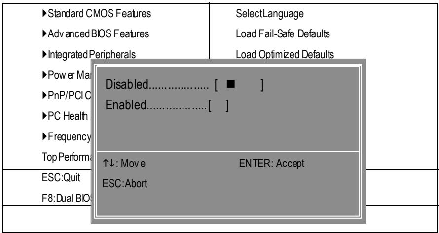
Figure 9: Top Performance
Top Performance
If you wish to maximize the performance of your system, set "Top Performance" as "Enabled".
Disabled Disable this function. (Default Value)
Enabled Enable Top Performance function.
"Top Performance" will increase H/W working speed. Different system configuration (both H/W component and OS) will effect the result. For example, the same H/W configuration might not run properly with Windows XP, but works smoothly with Windows NT. Therefore, if your system is not perform enough, the reliability or stability problem will appear sometimes, and we will recommend you disabling the option to avoid the problem as mentioned above.
SelectLanguage
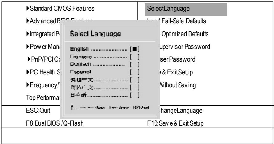
Figure 10:Select Language
CMOS Setup Utility -Copy right (C) 1984-2003 Award Software
Select Language
Multi Language is supports 7 languages. There are English, Japanese, French, Spanish, Germany, Simplified Chinese, Traditional Chinese.
LoadFail-Safe Defaults
CMOS Setup Utility -Copy right (C) 1984-2003 Award Software
Figure 11: Load Fail-Safe Defaults
| Standard CMOS Features | SelectLanguage |
| Advanced BIOS Features | Load Fail-Safe Defaults |
| Integrated Peripherals | Load Optimized Defaults |
| Power Management Setup | SetSupervisor Password |
| PnP/PCI Configurations | SetUserPassword |
| PC H: Load Fail-Safe Defaults? (Y/N)?N | |
| Top Performance | |
| ESC:Quit | F3:ChangeLanguage |
| F8:Dual BIOS /Q-Flash | F10:Save & Exit Setup |
| Load Fail-Safe Defaults | |
Load Fail-Safe Defaults
Fail-Safe defaults contain the most appropriate values of the system parameters that allow minimum systeem performance.
Load Optimized Defaults
CMOS Setup Utility -Copy right (C) 1984-2003 Award Software
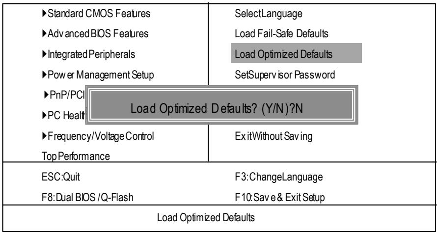
Figure 12: Load Optimized Defaults
Load Optimized Defaults
Selecting this field loads the factory defaults for BIOS and Chipset Features which the system automatically detects.
Set Supervisor/User Password
CMOS Setup Utility -Copy right (C) 1984-2003 Award Software
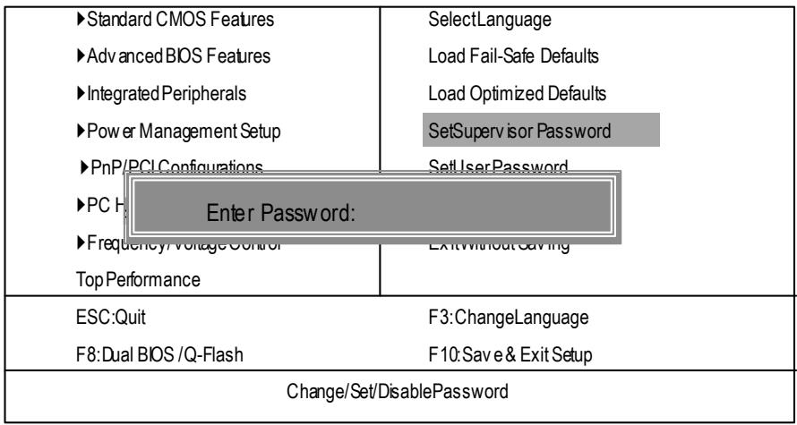
Figure 13: Password Setting
When you select this function, the following message will appear at the center of the screen to assist you in creating a password.
Type the password, up to eight characters, and press
To disable password, just press
The BIOS Setup program allows you to specify two separate passwords: a SUPERVISOR PASSWORD and a USER PASSWORD. When disabled, anyone may access all BIOS Setup program function. When enabled, the Supervisor password is required for entering the BIOS Setup program and having full configuration fields, the User password is required to access only basic items.
If you select "System" at "Security Option" in Advance BIOS Features Menu, you will be prompted for the password every time the system is rebooted or any time you try to enter Setup Menu.
If you select "Setup" at "Security Option" in Advance BIOS Features Menu, you will be prompted only when you try to enter Setup.
Save & Exit Setup
CMOS Setup Utility -Copy right (C) 1984-2003 Award Software
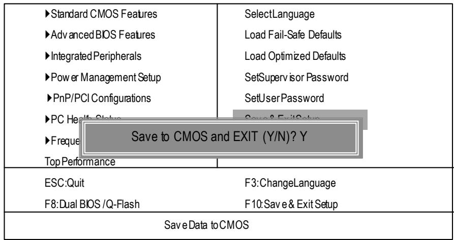
Figure 14: Save & Exit Setup
Type "Y" will quit the Setup Utility and save the user setup value to RTC CMOS.
Type "N" will return to Setup Utility.
Exit Without Saving
CMOS Setup Utility -Copy right (C) 1984-2003 Award Software
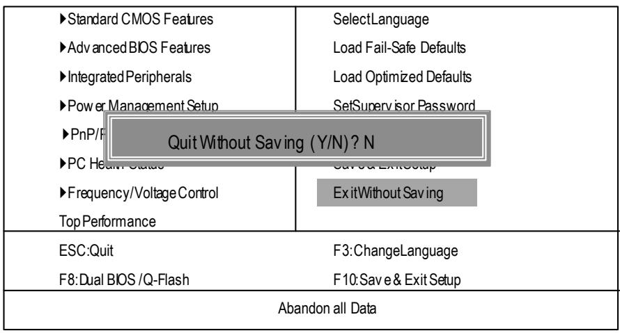
Figure 15: Exit Without Saving
Type "Y" will quit the Setup Utility without saving to RTC CMOS.
Type "N" will return to Setup Utility.
Chapter 4 Technical Reference
@ BIOS Introduction
Gigabyte announces @BIOS Windows BIOS live update utility

Have you ever updated BIOS by yourself? Or like many other people, you just know what BIOS is, but always hesitate to update it? Because you think updating newest BIOS is unnecessary and actually you don't know how to update it
Maybe not like others, you are very experienced in BIOS updating and spend quite a lot of time to do it. But of course you don't like to do it too much. First, download different BIOS from website and then switch the operating system to DOS mode. Secondly, use different flash utility to update BIOS. The above process is not a interesting job. Besides, always be carefully to store the BIOS source code correctly in your disks as if you update the wrong BIOS, it will be a nightmare.
Certainly, you wonder why motherboard vendors could not just do something right to save your time and effort and save you from the lousy BIOS updating work? Here it comes! Now Gigabyte announces @BIOS—the first Windows BIOS live update utility. This is a smart BIOS update software. It could help you to download the BIOS from internet and update it. Not like the other BIOS update software, it's a Windows utility. With the help of "@BIOS", BIOS updating is no more than a click.
Besides, no matter which mainboard you are using, if it's a Gigabyte's product*, @BIOS help you to maintain the BIOS. This utility could detect your correct mainboard model and help you to choose the BIOS accordingly. It then downloads the BIOS from the nearest Gigabyte ftp site automatically. There are several different choices; you could use "Internet Update" to download and update your BIOS directly. Or you may want to keep a backup for your current BIOS, just choose "Save Current BIOS" to save it first. You make a wise choice to use Gigabyte, and @BIOS update your BIOS smartly. You are now worry free from updating wrong BIOS, and capable to maintain and manage your BIOS easily. Again, Gigabyte's innovative product erects a milestone in mainboard industries.
For such a wonderful software, how much it costs? Impossible! It's free! Now, if you buy a Gigabyte's motherboard, you could find this amazing software in the attached driver CD. But please remember, connected to internet at first, then you could have a internet BIOS update from your Gigabyte @BIOS.
Easy Tune™ 4 Introduction
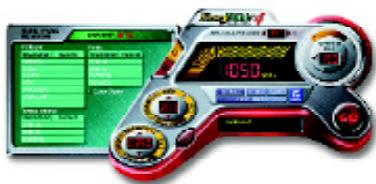
Gigabyte announces EasyTuneTM 4 Windows based Overclocking utility
EasyTune 4 carries on the heritage so as to pave the way for future generations.
Overclock" might be one of the most common issues in computer field. But have many users ever
tried it? The answer is probably "no". Because "Overclock" is thought to be very difficult and includes a lot of technical know-how, sometimes "Overclock" is even considered as special skills found only in some enthusiasts. But as to the experts in "Overclock", what's the truth? They may spend quite a lot of time and money to study, try and use many different hardware or BIOS tools to do "Overclock". And even with these technologies, they still learn that it's quite a risk because the safety
and stability of an "Overclock" system is unknown. Now everything is different because of a Windows based overclocking utility "EasyTune 4" --announced by Gigabyte. This windows based utility has totally changed the gaming rule of "Overclock". This is the first windows based overclocking utility is suitable for both normal and power users. Users can choose either "Easy Mode" or "Advanced Mode" for overclocking at their convenience. For users who choose "Easy Mode", they just need to click "Auto Optimize" to have autbed and immediate CPU overclocking. This software will then overdrive CPU speed automatically with the result being shown in the control panel. If users prefer "Overclock" by them, there is also another choice. Click "Advanced Mode" to enjoy "sport drive" class Overclocking user interface. "Advanced Mode", allows users to change the system bus / AGP / Memory working frequency in small increments to get ultimate system performance. It operates in coordination with Gigabyte motherboards. Besides, it is different from other traditional overclocking methods, EasyTune 4 doesn't require users to change neither BIOS nor hardware switch/ jumper setting; on the other hand, they can do "Overclock" at easy step. Therefore, this is a safer way for "Overclock" as nothing is changed on software or hardware. If user runs EasyTune 4 over system's limitation, the biggest lost is only to restart the computer again and the side effect is then well controlled. Moreover, if one well-performed system speed has been tested in EasyTune 4, user can "Save" this setting and "Load" it in next time. Obviously, Gigabyte EasyTune 4 has already turned the "Overclock" technology toward a newer generation. This wonderful software is now free bundled in Gigabyte motherboard attached in driver CD. Users may make a test drive of "EasyTune 4" to find out more amazing features by themselves.
*Some Gigabyte products are not fully supported by EasyTune 4. Please find the products supported list in the web site.
*Any "Overclocking action" is at user's risk, Gigabyte Technology will not be responsible for any damage or instability to your processor, motherboard, or any other components.
Face-Wizard Utilities Installation
WhatisFace-WizardTM?
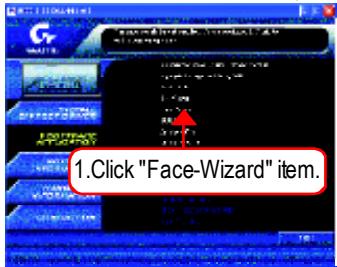
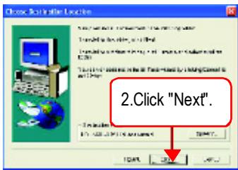
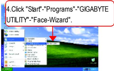
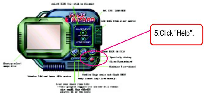
Face-Wizard™ is a windows based utility with user-friendly interface that allows users to change the boot-up logo with picture from Gigabyte Logo Gallery on web site or other compatible picture you have.
How does it work?
Face-Wizard™ allows user to select BIOS on board or file in hard drive, floppy disk, zip, MO or other storage devices and combine the compatible picture you prefer into BIOS. And not only this, Face-Wizard™ also helps user to update BIOS in windows mode.
What's benefit for using Face-Wizard™?
It can personalize boot-up logo to show your unique style from others, and never again looking at the black and white bootup screen.
(1)
(2)

(3)
(4)
(5)
BIOS Flash Procedure

Method 1:
We use GA-7VTX motherboard and Flash841 BIOS flash utility as example.
Please flash the BIOS according to the following procedures if you are now under the DOS mode.
Flash BIOS Procedure:
STEP 1:
(1) Please make sure your system has installed the extraction utility such as winzip or pkunzip. Firstly you have to install the extraction utility such as winzip or pkunzip for unzip the files. Both of these utilities are available on many shareware download pages like http://www.cnet.com
STEP 2: Make a DOS boot diskette. (See example: Windows 98 O.S.)
Beware: Windows ME/2000 are not allowed to make a DOS boot diskette.
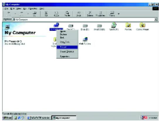
(1) With an available floppy disk in the floppy drive. Please leave the diskette "UN-write protected" type. Double click the "My Computer" icon from Desktop, then click "3.5 diskette (A)" and right click to select "Format (M)"
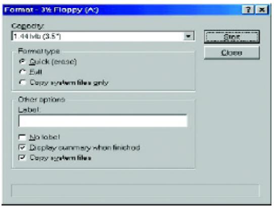
(2) Select the "Quick (erase)" for Format Type, and pick both "Display summary when finished" and "Copy system files", after that press "Start". That will format the floppy and transfer the needed system files to it.
Beware: This procedure will erase all the prior data on that floppy, so please proceed accordingly.
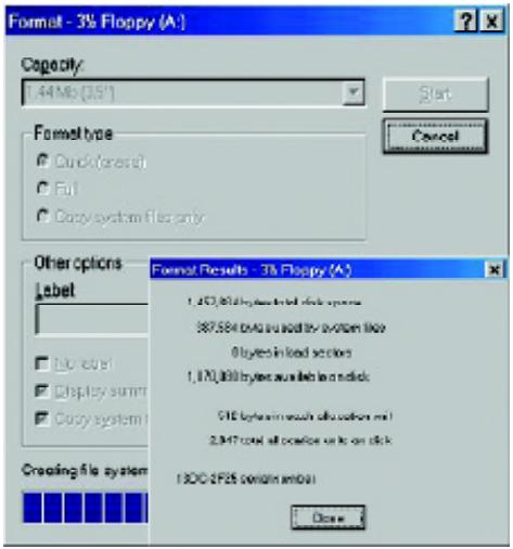
(3) After the floppy has been formatted completely, please press "Close".
STEP 3: Download BIOS and BIOS utility program.
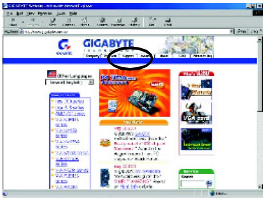
(1) Please go to Gigabyte website http://www.gigabyte.com.tw/index.html, and click "Support".
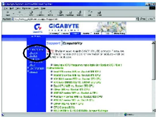
(2) From Support zone, click the "Motherboards BIOS & Drivers".
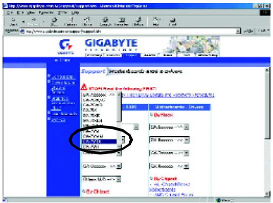
(3) We use GA-7VTX motherboard as example. Please select GA-7VTX by Model or Chipset optional menu to obtain BIOS flash files.
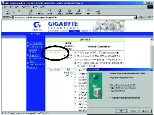
(4) Select an appropriate BIOS version (For example: F4), and click to download the file. It will pop up a file download screen, then select the "Open this file from its current location" and press "OK".
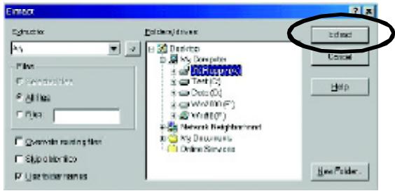
(5) At this time the screen shows the following picture, please click "Extract" button to unzip the files.

(6) Please extract the download files into the clean bootable floppy disk A mentioned in STEP 2, and press "Extract".
STEP 4: Make sure the system will boot from the floppy disk.
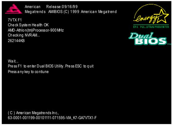
(1) Insert the floppy disk (contains bootable program and unzip file) into the floppy drive A. Then, restart the system. The system will boot from the floppy disk. Please press key to enter BIOS setup main menu when system is boot up.
(2) Once you enter the BIOS setup utility, the main menu will appear on the screen. Use the arrows to highlight the item "BIOS FEATURES SETUP".
| AMIBIOS SIMPLE SETUP UTILITY - VERSION 1.24b (C) 1999 American Megatrends, Inc. All Rights Reserved | |
| STANDARD CMOS SETUP | INTEGRATED PERIPHERALS |
| BIOS FEATURES SETUP | HARDWARE MONITOR & MISC SETUP |
| CHIPSET FEATURES SETUP | SUPERVISOR PASSWORD |
| POWER MANAGEMENT SETUP | USER PASSWORD |
| PNP / PCI CONFIGURATION | IDE HDD AUTO DETECTION |
| LOAD BIOS DEFAULTS | SAVE & EXIT SETUP |
| LOAD SETUP DEFAULTS | EXIT WITHOUT SAVING |
| ESC: Quit ↑↓←→ : Select Item (Shift)F2: Change Color F5: Old Values | |
| F6: Load BIOS Defaults F7: Load Setup Defaults F10: Save & Exit | |
| Time, Date, Hard Disk Type... | |
(3) Press "Enter" to enter "BIOS FEATURES SETUP" menu. Use the arrows to highlight the item "1st Boot Device", and then use the "Page Up" or "Page Down" keys to select "Floppy".
| AMIBIOS SETUP - BIOS FEATURES SETUP (C.) 2001 American Megatrends, Inc. All Rights Reserved | |
| 1st Boot Device : Floppy 2nd Boot Device : IDE-0 3rd Boot Device : CDROM S.M.A.R.T. for Hard Disks : Disabled BootUp Num-Lock : On Floppy Drive Seek : Disabled Password Check : Setup | ESC: Quit ↑↓←→: Select Item F1 : Help PU/PD/+/-: Modify F5 : Old Values (Shift)F2: Color F6 : Load BIOS Defaults F7 : Load Setup Defaults |
(4) Press "ESC" to go back to previous screen. Use the arrows to highlight the item "SAVE & EXIT SETUP" then press "Enter". System will ask "SAVE to CMOS and EXIT (Y/N)?" Press "Y" and "Enter" keys to confirm. Now the system will reboot automatically, the new BIOS setting will be taken effect next boot-up.
| AMIBIOS SIMPLE SETUP UTILITY - VERSION 1.24b (C) 2001 American Megatrends, Inc. All Rights Reserved | |
| STANDARD CMOS SETUPBIOS FEATURES SETUPCHIPSET FEATURES SETUPPOWER MANAGEMENT SETUPPNP / PCI CONFIGSave to CMOS and EXIT (Y/N)? YLoad BIOS DEFAULTSLOAD SETUP DEFAULTS | INTEGRATED PERIPHERALSHARDWARE MONITOR & MISC SETUPSUPERVISOR PASSWORDUSER PASSWORDSAVE & EXIT SETUPEXIT WITHOUT SAVING |
| ESC: Quit ↑↓←→ : Select Item (Shift)F2: Change Color F5: Old ValuesF6: Load BIOS Defaults F7: Load Setup Defaults F10: Save & ExitSave Data to CMOS & Exit SETUP | |
STEP 5: BIOS flashing.
(1) After the system boot from floppy disk, type "A:> dir/w" and press "Enter" to check the entire files in floppy A. Then type the "BIOS flash utility" and "BIOS file" after A:>. In this case you have to type "A:> Flash841 7VTX.F4" and then press "Enter".
Starting Windows 98...
Microsoft(R) Windows98
Copyright Microsoft Corp 1981-1999
A:>dir/w
Volume in drive A has no label
Volume Serial Number is 16EB-353D
Directory of A:\
COMMAND.COM 7VTX.F4 FLASH841.EXE
3 file(s) 838,954 bytes
0 dir(s) 324,608 bytes free
A:Flash841 7VTX.F4
(2) Now screen appears the following Flash Utility main menu. Press "Enter", the highlighted item will locate on the model name of the right-upper screen. Right after that, press "Enter" to start BIOS Flash Utility.
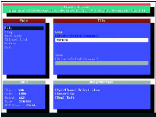
(3) It will pop up a screen and asks "Are you sure to flash the BIOS?" Press [Enter] to continue the procedure, or press [ESC] to quit.
Beware: Please do not turn off the system while you are upgrading BIOS. It will render your BIOS corrupted and system totally inoperative.
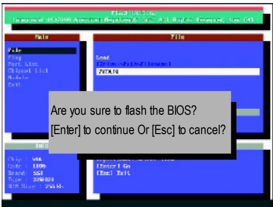
(4) The BIOS flash completed. Please press [ESC] to exit Flash Utility.

STEP 6: Load BIOS defaults.
Normally the system redetects all devices after BIOS has been upgraded. Therefore, we highly recommend reloading the BIOS defaults after BIOS has been upgraded. This important step resets everything after the flash.
(1) Take out the floppy diskette from floppy drive, and then restart the system. The boot up screen will indicate your motherboard model and current BIOS version.
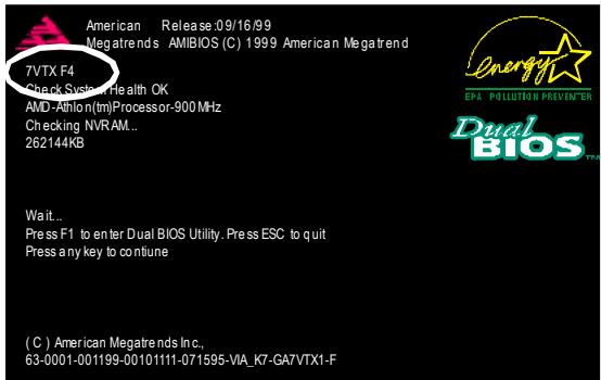
(2) Don't forget to press key to enter BIOS setup again when system is boot up. Use the arrows to highlight the item "LOAD SETUP DEFAULTS" then press "Enter". System will ask "Load Setup Defaults (Y/N)?" Press "Y" and "Enter" keys to confirm.
| AMIBIOS SIMPLE SETUP UTILITY - VERSION 1.24b (C) 2001 American Megatrends, Inc. All Rights Reserved | |
| STANDARD CMOS SETUPBIOS FEATURES SETUPCHIPSET FEATURES SETUPPOWER MANAGERPNP / PCI CONFIGLoad Setup Defaults? (Y/N)?NLOAD BIOS DEFAULTSLOAD SETUP DEFAULTS | INTEGRATED PERIPHERALSHARDWARE MONITOR & MISC SETUPSUPERVISOR PASSWORD |
| SAVE & EXIT SETUPEXIT WITHOUT SAVING | |
| ESC: Quit ↑↓←→ : Select Item (Shift)F2 : Change Color F5: Old ValuesF6: Load BIOS Defaults F7: Load Setup Defaults F10: Save & Exit | |
| Load Setup Defaults | |
(3) Use the arrows to highlight the item "SAVE & EXIT SETUP" and press "Enter". System will ask "SAVE to CMOS and EXIT (Y/N)?" Press "Y" and "Enter" keys to confirm. Now the system will reboot automatically, the new BIOS setting will be taken effect next boot-up.
| AMIBIOS SIMPLE SETUP UTILITY - VERSION 1.24b (C) 2001 American Megatrends, Inc. All Rights Reserved | |
| STANDARD CMOS SETUPBIOS FEATURES SETUPCHIPSET FEATURES SETUPPOWER MANAGEMENT SETUPPNP / PCI CONFIGSave to CMOS and EXIT (Y/N)? YLoad BIOS DEFAULTSLOAD SETUP DEFAULTS | INTEGRATED PERIPHERALSHARDWARE MONITOR & MISC SETUPSUPERVISOR PASSWORDUSER PASSWORD |
| SAVE & EXIT SETUPEXIT WITHOUT SAVING | |
| ESC: Quit ↑↓←→ : Select Item (Shift)F2 : Change Color F5: Old ValuesF6: Load BIOS Defaults F7: Load Setup Defaults F10: Save & Exit | |
| Save Data to CMOS & Exit SETUP | |
(4) Congratulate you have accomplished the BIOS flash procedure.
Method 2:
Dual BIOS / Q-Flash Introduction
A. What is Dual BIOS Technology?
Dual BIOS means that there are two system BIOS (ROM) on the motherboard, one is the Main BIOS and the other is Backup BIOS. Under the normal circumstances, the system works on the Main BIOS. If the Main BIOS is corrupted or damaged, the Backup BIOS can take over while the system is powered on. This means that your PC will still be able to run stably as if nothing has happened in your BIOS.
B. How to use Dual BIOS and Q-Flash Utility?
a. After power on the computer, pressing immediately during POST (Power On Self Test) it will allow you to enter Award BIOS CMOS SETUP, then press
CMOS Setup Utility-Copyright(C) 1984-2002 Award Software
| Standard CMOS Features | Select Language |
| Advanced BIOS Features | Load Fail-Safe Defaults |
| Integrated Peripherals | Load Optimized Defaults |
| Power Management Setup | Set Supervisor Password |
| PnP/PCI Configurations | Set User Password |
| PC Health Status | Save & Exit Setup |
| Frequency/Top Performa | Enter Dual BIOS / Q-Flash Utility (Y/N)? Y |
| ESC:Quit | F3:ChangeLanguage |
| F8:Dual BIOS /Q-Flash | F10:Save & Exit Setup |
b. Dual BIOS / Q-Flash Utility
| Dual BIOS / Q-Flash Utility V845.4MF3 (C) 2001, GIGA-BYTE Technology Co., LTD. | |
| Wide Range Protection | :Disabled |
| Halt On BIOS Defects | :Disabled |
| Auto Recovery | :Enabled |
| Boot From | :Main BIOS |
| BIOS Recovery | :Main to Backup |
| F3: Load Default | F5:Start BIOS Recovery |
| F7: Save And Restart | F9:Exit Without Saving |
| F8: Update BIOS from disk | F10:Recovery from Disk |
| Use <Space> key to toggle setup | |
c. Dual BIOS Item explanation:
Wide Range Protection: Disabled(Default), Enabled
Status 1:
If any failure (ex. Update ESCD failure, checksum error or reset...) occurs in the Main BIOS, just before the Operating System is loaded and after the power is on, and that the Wide Range Protection is set to "Enable", the PC will boot from Backup BIOS automatically.
Status 2:
If the ROM BIOS on peripherals cards(ex. SCSI Cards, LAN Cards,...) emits signals to request restart of the system after the user make any alteration on it, the boot up BIOS will not be changed to the Backup BIOS.
Halt On BIOS Defects : Disabled(Default), Enabled
If the BIOS occurs a checksum error or the Main BIOS occurs a WIDE RANGE PROTECTION error and Halt On BIOS Defects set to Enable, the PC will show messages on the boot screen, and the system will pause and wait for the user's instruction.
If Auto Recovery:Disabled, it will show
If Auto Recovery:Enabled, it will show
Auto Recovery: Enabled(Default), Disabled
When one of the Main BIOS or Backup BIOS occurs checksum failure, the working BIOS will automatically recover the BIOS of checksum failure.
(In the Power Management Setup of the BIOS Setting, if ACPI Suspend Type is set to Suspend to RAM, the Auto Recovery will be set to Enable automatically.)
(If you want to enter the BIOS setting, please press "Del" key when the boot screen appears.)
Boot From: Main BIOS(Default), Backup BIOS
Status 1:
The user can set to boot from main BIOS or Backup BIOS.
Status 2:
If one of the main BIOS or the Backup BIOS fails, this item "Boot From : Main BIOS(Default)
" will become gray and will not be changed by user.
BIOS Recovery : Main to Backup
Auto recovery message:
BIOS Recovery: Main to Backup
The means that the Main BIOS works normally and could automatically recover the Backup BIOS.
BIOS Recovery: Backup to Main
The means that the Backup BIOS works normally and could automatically recover the Main BIOS.
(This auto recovery utility is set by system automatically and can't be changed by user.)
C. What is Q-Flash Utility?
Q-Flash utility is a pre-O.S. BIOS flash utility enables users to update its BIOS within BIOS mode, no more fooling around any OS.
D. How to use Q-Flash Flash?
| F3: Load Default Load current BIOS default value. | F5: Start BIOS Recovery Press F5 to recovery new BIOS version. |
| F7: Save and Restart Save revised setting and restart the computer. | F9: Exit Without Saving Exit without changing. |
| F8: Update BIOS from Disk Update boot-up BIOS. | F10: Recovery from Disk Update another BIOS (different from boot-up BIOS) |

DualBIOST™ Technology FAQ
GIGABYTE Technology is pleased to introduce DualBIOS technology, a hot spare for your system BIOS. This newest "Value-added" feature, in a long series of innovations from GIGABYTE, is available on this mainboard. Future GIGABYTE motherboards will also incorporate this innovation.
What's DualBIOS™?
On GIGABYTE motherboards w6ith DualBIOS there are physically two BIOS chips. For simplicity we'll call one your "Main BIOS" and the other we'll call your "Backup" BIOS (your "hot spare"). If your Main BIOS fails, the Backup BIOS almost automatically takes over on your next system boot. Almost automatically and with virtually zero down time! Whether the problem is a failure in flashing your BIOS or a virus or a catastrophic failure of the Main BIOS chip, the result is the same - the Backup BIOS backs you up, almost automatically.
I. Q: What is DualBIOSTM technology?
Answer:
DualBIOS technology is a patented technology from Giga-Byte Technology. The concept of this technology is based on the redundancy and fault tolerance theory. DualBIOSTM technology simply means there are two system BIOSes (ROM) integrated onto the motherboard. One is a main BIOS, and the other is a backup BIOS. The mainboard will operate normally with the main BIOS, however, if the main BIOS is corrupt or damaged for various reasons, the backup BIOS will be automatically used when the system powered-On. Your PC will operate as before the main BIOS was damaged, and is completely transparent to the user.
II. Q: Why does anyone need a motherboard with DualBIOS™ technology?
Answer:
In today's systems there are more and more BIOS failures. The most common reasons are virus attacks, BIOS upgrade failures, and/or deterioration of the BIOS (ROM) chip itself.
- New computer viruses are being found that attack and destroy the system BIOS. They may corrupt your BIOS code, causing your PC to be unstable or even not boot normally.
- BIOS data will be corrupted if a power loss/surge occurs, or if a user resets the system, or if the power button is pressed during the process of performing a system BIOS upgrade.
- If a user mistakenly updates their mainboard with the incorrect BIOS file, then the system may not be able to boot correctly. This may cause the PC system hang in operation or during boot.
- A flash ROM's life cycle is limited according to electronic characteristics. The modern PC utilizes the Plug and Play BIOS, and is updated regularly. If a user changes peripherals often, there is a slight chance of damage to the flash ROM.
With Giga-Byte Technology's patented DualBIOST™ technology you can reduce the possibility of hangs during system boot up, and/or loss BIOS data due to above reasons. This new technology will eliminate valuable system down time and costly repair bills cause by BIOS failures.
III. Q: How does DualBIOS™ technology work?
Answer:
- DualBIOST™ technology provides a wide range of protection during the boot up procedure. It protects your BIOS during system POST, ESCD update, and even all the way to PNP detection/assignment.
- DualBIOST™ provides automatic recovery for the BIOS. When the first BIOS used during boot up does not complete or if a BIOS checksum error occurs, boot-up is still possible. In the DualBIOST™ utility, the "Auto Recovery" option will guarantee that if either the main BIOS or backup BIOS is corrupted, the DualBIOST™ technology will use the good BIOS and correct the wrong BIOS automatically.
- DualBIOST™ provides manual recovery for the BIOS. DualBIOST™ technology contains a built-in flash utility, which can flash your system BIOS from backup to main and/or visa versa. There is no need for an OS-dependent flash utility program.
- DualBIOST™ contains a one-way flash utility. The built-in one-way flash utility will ensure that the corrupt BIOS is not mistaken as the good BIOS during recovery and that the correct BIOS (main vs. backup) will be flashed. This will prevent the good BIOS from being flashed.
IV. Q: Who Needs DualBIOSTM technology?
Answer:
- Every user should have DualBIOST™ technology due to the advancement of computer viruses.
Everyday, there are new BIOS-type viruses discovered that will destroy your system BIOS. Most commercial products on the market do not have solutions to guard against this type of virus intrusion. The DualBIOSTM technology will provide a state-of-the-art solution to protect your PC:
Case I.) Vicious computer viruses may wipe out your entire system BIOS. With a conventional single system BIOS PC, the PC will not be functional until it is sent for repairs.
Case II.) If the "Auto Recovery" option is enabled in the DualBIOST™ utility, and if a virus corrupts your system BIOS, the backup BIOS will automatically reboot the system and correct the main BIOS.
Case III.) A user may override booting from the main system BIOS. The DualBIOSTTM
utility may be entered to manually change the boot sequence to boot from the backup BIOS.
- During or after a BIOS upgrade, if DualBIOST™ detects that the main BIOS is corrupt, the backup BIOS will take over the boot-up process automatically. Moreover, it will verify the main and backup BIOS checksums when booting-up. DualBIOST™ technology examines the checksum of the main and backup BIOS while the system is powered on to guarantee your BIOS operates properly.
- Power Users will have the advantage of having two BIOS versions on their mainboard. The benefit is being able to select either version BIOS to suit the performance system needs.
- Flexibility for high-end desktop PCs and workstation/servers. In the DualBIOST™ utility, the option can be set, "Halt On When BIOS Defects," to be enabled to halt your system with warning message that the main BIOS has been corrupted. Most workstation/servers require constant operation to guarantee services have not been interrupted. In this situation, the "Halt On When BIOS Defects" message may be disabled to avoid system pauses during normal booting. Another advantage you gain from Giga-Byte's DualBIOST™ technology is the ability to upgrade from dual 2 Mbit BIOS to dual 4 Mbit BIOS in the future if extra BIOS storage is needed.

Method 3:
If you don't have DOS boot disk, we recommend that you used Gigabyte @BIOST™ program to flash BIOS.
Follow the setup that showing on the sween to install the Utility.

(1)
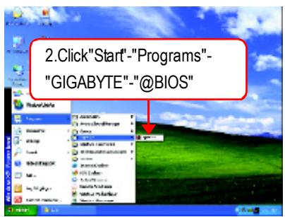
(2)
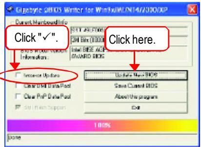
(3)
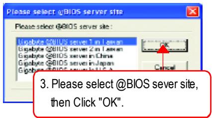
(4)
Methods and steps:
I. Update BIOS through Internet
a. Click "Internet Update" icon
b. Click "Update New BIOS" icon
c. Select@BIOST™ sever
d. Select the exact modelname on your motherboard
e. System will automatically download and update the BIOS.
II. Update BIOS NOT through Internet
a. Do not click "Internet Update" icon
b. Click "Update New BIOS"
c. Please select "All Files" in dialog box while opening the old file.
d. Please search for BIOS unzip file, downloading from internet or any other methods (such as: 8PE800U.F1).
e. Complete update process following the instruction.
III. Save BIOS
In the very beginning, there is "Save Current BIOS" icon shown in dialog box. It means to save the current BIOS version.
IV. Check out supported motherboard and Flash ROM:
In the very beginning, there is "About this program" icon shown in dialog box. It can help you check out which kind of motherboard and which brand of Flash ROM are supported.
Note:
a. In method I, if it shows two or more motherboard's model names to be selected, please make sure your motherboard's model name again. Selecting wrong model name will cause the system unbooted.
b. In method II, be sure that motherboard's model name in BIOS unzip file are the same as your motherboard's. Otherwise, your system won't boot
c. In method I, if the BIOS file you need cannot be found in @BIOSTM server, please go onto Gigabyte's web site for downloading and updating it according to method II.
d. Please note that any interruption during updating will cause system unbooted
2-/4-/6-Channel Audio Function Introduction
The installation of windows 98SE/2K/ME/XP is very simple. Please follow next step to install the function!
Stereo Speakers Connection and Settings:
We recommend that you use the speaker with amplifier to acquire the best sound effect if the stereo output is applied.
STEP1:
Connect the stereo speakers or earphone to "Line Out".
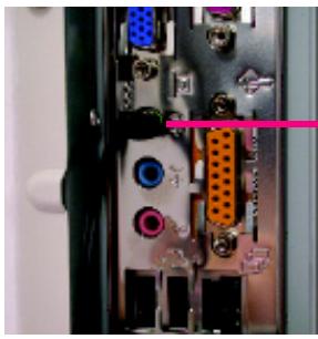
Line Out
STEP2:
After installation of the audio driver, you'll find an icon on the taskbar's status area. Click the audio icon "Sound Effect" from the windows tray at the bottom of the screen.

STEP3:
Select "Speaker Configuration", and choose the "2 channels for stereo speakers output".

2 channels mode for stereo speakers output
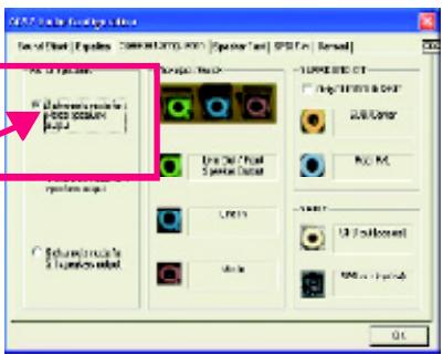
4 Channel Analog Audio Output Mode
STEP1:
Connect the front channels to "Line Out", the rear channels to "Line In".

STEP2:
After installation of the audio driver, you'll find an icon on the taskbar's status area. Click the audio icon "Sound Effect" from the windows tray at the bottom of the screen.

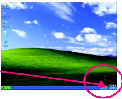
STEP3:
Select "Speaker Configuration", and choose the "4 channels for 4 speakers output".
Disable "Only SURROUND-KIT", and press "OK".
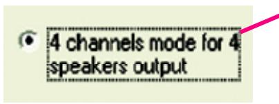

When the "Environment settings" is "None", the sound would be performed as stereo mode
(2 channels output). Please select the other settings for 4 channels output.
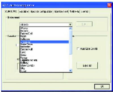
Basic 6 Channel Analog Audio Output Mode
Use the back audio panel to connect the audio output without any additional module.
STEP1:
Connect the front channels to "Line Out", the rear channels to "Line In", and the Center/Subwoofer channels to "MIC In".
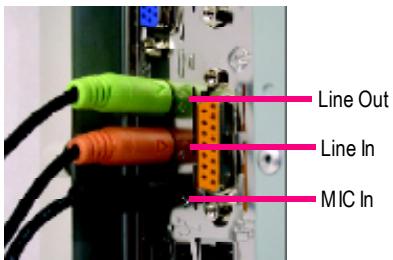
STEP2:
After installation of the audio driver, you'll find an icon on the taskbar's status area. Click the audio icon "Sound Effect" from the windows tray at the bottom of the screen.

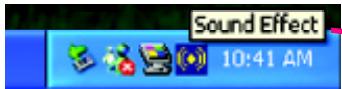
STEP3:
Select "Speaker Configuration", and choose the "6 channels for 5.1 speakers out put".
Disable "Only SURROUND-KIT" and pess "OK"

6 channels mode for 5.1 speakers output
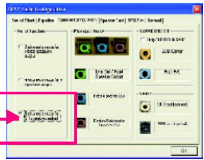
Advanced 6 Channel Analog Audio Output Mode (using Audio Combo Kit, Optional Device):
(Audio Combo Kit provides SPDIF output port : optical & coaxis and SURROUND-KIT : Rear R/L & CEN /
Subwoofer)
SURROUND-KIT access analog output to rear
channels and Center/Subwoofer channels. It is the best solution if you need 6 channel output, Line In and MIC at the same time. "SURROUND-KIT" is included in the GIGABYTE unique "Audio Combo Kit" as picture.
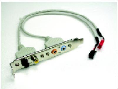
STEP1:
Insert the "Audio Combo Kit" in the back of the case, and fix it with the screw.

STEP2:
Connect the "SURROUND-KIT" to SUR_CEN on the M/B.

STEP3:
Connect the frontchannels to back audio panel's
"Line Out", the rear channels to SURROUND-KIT's REAR R/L, and the Center/Subwoofer channels to SURROUND-KIT's SUB CENTER.
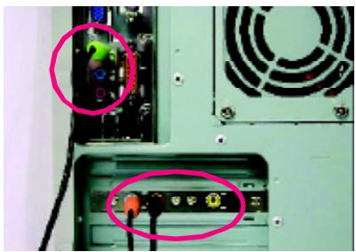
STEP4:
Click the audio icon "Sound Effect" from the windows tray at the bottom of the screen.
STEP5:
Select"Speaker Configuration", and choose the "6 channels for 5.1 speakers output".
Enable"Only SURROUND-KIT" and press "OK".
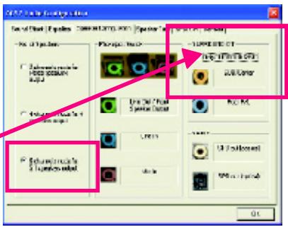
SURROUND-KIT
Only SURROUND-KIT
Basic & Advanced 6 Channel Analog Audio Output ModeNotes:
When the "Environment settings" is "None", the sound would be performed as stereo mode(2 channels output). Please select the other settings for 6 channels output.
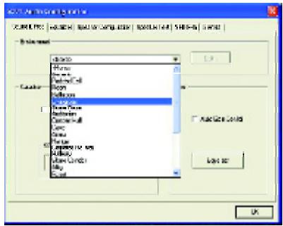
SPDIF Output Device (Optional Device)
A "SPDIF output" device is available on the motherboard. Cable with rear bracket is provided and could link to the "SPDIF output" connector (As picture.) For the further linkage to decoder, rear bracket provides coaxial cable and Fiber connecting port.
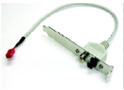
- Connect the SPDIF output device to the rear bracket of PC, and fix it with screw.
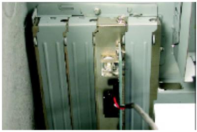
- Connect SPDIF wire to the motherboard.
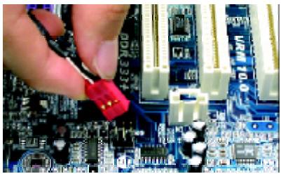
- Connect co-axial or optical output to the SPDIF decoder.
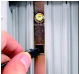
Chapter 5 Appendix
Install Drivers

Picture below are shown in Windows XP (IUCD ver 2.22)
Insert the driver CD-title that came with your motherboard into your CD-ROM drive, the driver CD-title will auto start and show the installation guide. If not, please double click the CD-ROM device icon in "My computer", and execute the setup.exe.
INSTALL CHIPSET DRIVER
This page shows the drivers that need to be installed for the system. Click each item to install the driver manually or switch to the X to install the drivers automatically.
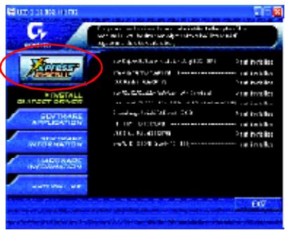
The "Xpress Install" uses the "Click and Forget" technology to install the drivers automatically. Just select the drivers you want then click the "GO" button. The will finish the installation for you automatically.
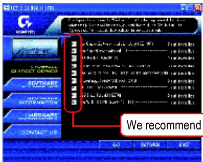

Massage: Some device drivers will restart your system automatically. After restarting your system the "Xpress Install" will continue to install other drivers.
We recommend that you install all components in the list.


Driver install finished!
You have to reboot system!
Item Description
Intel Chipset Software Installation Utility
Tell the operating system how the chipset components will be configured
Intel Application Accelerator
Designed to improve performance of the storage sub-system and overall system performance
USB Path for WinXP
This patch driver can help you to resolve the USB device wake up S3 hang up issue in XP
Intel82562/82562EX/82540EM LAN Driver
For Intel(R) PRO/10/100/1000/Wireless Ethernet connections
RealTekALC101A/201A/202/650AC97 Codec Driver
For Intel(R) ICH/ICH2/ICH4 AC97 audio
Silicon Image Serial-ATA Driver /Silicon Image RAID Driver
Serial-ATA /RAID Driver from Silicon Image.
ITE IT8212 RAID Driver 念
ITE IT8212 RAID Driver.
USB Driver Patch
This patch driver can help you to resolve some USB device issue on XP
Intel/NEC USB 2.0 Driver
It is recommended that you use the Microsoft Windows update for the most updated driver for XP/2K
- For GA-8PE800 Pro Only ◆For GA-8PE800 Pro-R Only ◆For GA-8PE800 Ultra Only
SOFTWAREAPPLICATION
This page reveals the value-added software developed by Gigabyte and its worldwide partners.
Gigabyte Windows Utilities Manager(GWUM)
This utility can integrate the Gigabyte's applications in the system tray
Gigabyte Management Tool(GMT)
A useful tool which can manage the computer via the network
EastTune4
Powerful utility that integrates the overclocking and hardware monitoring functions
DMI Viewer
Windows based utility which is used to browse the DMI/SMBIOS information of the system
Face-Wizard
New utility for adding BIOS logo
@BIOS
Gigabyte windows flash BIOS utility
Acrobat e-Book
Useful utility from Adobe
AcrobatReader
Popular utility from Adobe for reading .PDF file format documents
Norton Internet Security(NIS)
Integrated utility which includes anti-virus, ad control, etc.
Silicon Image SATA RAID utility (For RAID mode)
RAID utility for Silicon Image Serial-ATA 3112.
ITe Smart Card Reader Application
Utility from ITE which can read/write the GSM SIM/Smart card
Giga RAID Utility
RAID utility for ITE IT8212.

Please do not install "Silicon Image SIL3112 SATARaid Driver Utility" under WIN98 or WIN ME if there is no Serial ATA Deivce. For top per
formance and compatibility, it is recommend to use the SATA daughter Card which has Silicon Image Chipset.
- For GA-8PE800 Pro Only ◆For GA-8PE800 Pro-R Only ◆For GA-8PE800 Ultra Only
SOFTWARE INFORMATION
This page list the contacts of softwares and drivers in this CD title.
HARDWAREINFORMATION
This page lists all device you have for this motherboard.
CONTACTUS
Contact us via the information in this page all over the world.
FAQ
Below is a collection of general asked questions. To check general asked questions based on a specific motherboard model, please log on to http://tw.giga-byte.com/faq/faq.htm.
Question 1: I cannot see some options that were included in previous BIOS after updating BIOS. Why?
Answer: Some advanced options are hidden in new BIOS version. Please press "Ctrl" and "F1" keys after entering BIOS menu and you will be able to see these options.
Questions 2: Why is the light of my keyboard/optical mouse still on after computer shuts down? Answer: In some boards, a small amount of electricity is kept on standby after computer shuts down and that's why the light is still on.
Question 3: Why cannot I use all functions in EasyTuneTM4?
Answer: The availability of the listed functions in EasyTune™4 depends on the MB chipset. If the chipset doesn't support certain functions in EasyTune™4, these functions will be locked automatically and you will not be able to use them.
Question 4: Why do I fail to install RAID and ATA drivers under Win 2000 and XP on boards that support RAID function after I connect the boot HDD to IDE3 or IDE4?
Answer: First of all, you need to save some files in the CD-ROM to a floppy disk before installing drivers. You also need to go through some rather different steps in the installation process. Therefore, we suggest that you refer to the installation steps in the RAID manual at our website.
(Pleasesdowndlcathtp://tw.giga-byte.com/support/user(pdf/raid_manual.pdf)
Question 5: How do I clear CMOS?
Answer: If your board has a Clear CMOS jumper, please refer to the Clear CMOS steps in the manual. If your board doesn't have such jumper, you can take off the on-board battery to leak voltage to clear CMOS. Please refer to the steps below:
Steps:
- Turn off power.
- Disconnect the power cord from MB.
- Take out the battery gently and put it aside for about
10 minutes (Or you can use a metal object to connect the positive and negative pins in the battery holder to make them short for one minute).
- Re-insert the battery to the battery holder.
- Connect power cord to MB again and turn on power.
- Press Del to enter BIOS and load Fail-Safe Defaults.
- Save changes and reboot the system.
Question 6: Why does system seem unstable after updating BIOS?
Answer: Please remember to load Fail-Safe Defaults (Or Load BIOS Defaults) after flashing BIOS. However, if the system instability still remains, please clear CMOS to solve the problem.
Question 7: Why do I still get a weak sound after turning up the speaker to the maximum volume?
Answer: Please make sure the speaker you are using is equipped with an internal amplifier. If not, please change another speaker with power/amplifier and try again later.
Question 8: How do I disable onboard VGA card in order to add an external VGA card?
Answer: Gigabyte motherboards will auto-detect the external VGA card after it is plugged in, so you don't need to change any setting manually to disable the onboard VGA.
Question 9: Why cannot I use the IDE 2?
Please refer to the user manual and check whether you have connected any cable that is not provided with the motherboard package to the USB Over Current pin in the Front USB Panel. If the cable is your own cable, please remove it from this pin and do not connect any of your own cables to it.
Question 10: Sometimes I hear different continuous beeps from computer after system boots up. What do these beeps usually stand for?
Answer: The beep codes below may help you identify the possible computer problems. However, they are only for reference purposes. The situations might differ from case to case.
AMI BIOS Beep Codes
*Computer gives 1 shortbeep when system boots successfully.
*Except for beep code 8, these codes are always fatal.
1 beep Refresh failure
2 beeps Parity error
3 beeps Base 64K memory failure
4 beeps Timer not operational
5 beeps Processor error
6 beeps 8042 - gate A20 failure
7 beeps Processor exception interrupterror
8 beeps Display memory read/write failure
9 beeps ROM checksum error
10 beeps CMOS shutdown register read/write error
11 beeps Cache memory bad
AWARD BIOS Beep Codes
1 short System boots successfully
2 short CMOS setting error
1 long 1 short DRAM or M/B error
1 long 2 short: Monitor or display card error
1 long 3 short Keyboard error
1 long 9 short BIOS ROM error
Continuous long beeps: DRAM error
Continuous short beeps: Power error
Troubleshooting

If you encounter any trouble during boot up, please follow the troubleshooting procedures.
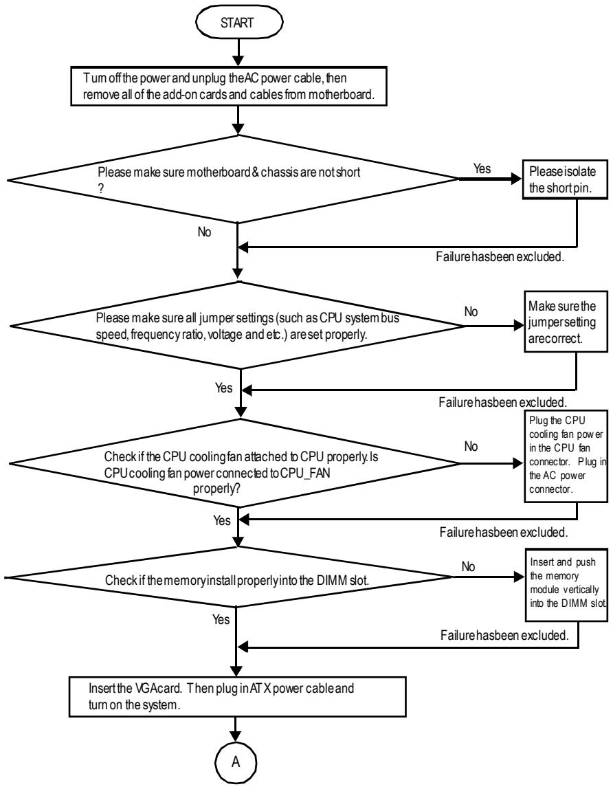
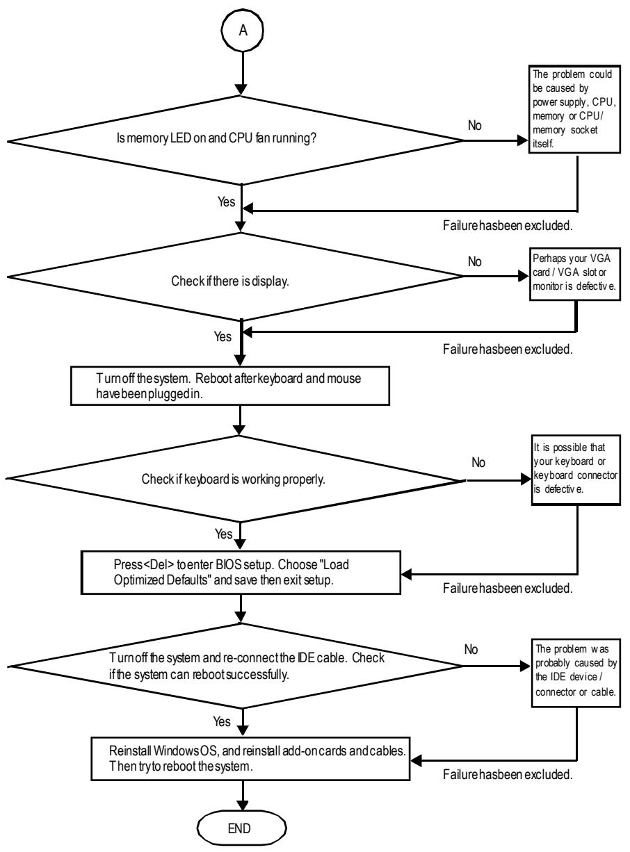
If the above procedure unable to solve your problem, please contact with your local retailer or national distributor for help. Or, you could submit your question to the service mail via Gigabyte website technical supportzone
(http://www.gigabyte.com.tw). The appropriate response will be provided ASAP.
Technical Support/RMA Sheet
| Customer/Country: | Company: | Phone No.: | |
| Contact Person: | E-mail Add. : | ||
| Modelname/LotNumber: | PCB revision: | |
| BIOS version: | O.S./A.S.: | |
| Hardware Configuration | Mfs. | Modelname | Size: | Driver/Utility: |
| CPU | ||||
| Memory Brand | ||||
| Video Card | ||||
| Audio Card | ||||
| HDD | ||||
| CD-ROM/DVD-ROM | ||||
| Modem | ||||
| Network | ||||
| AMR / CNR | ||||
| Keyboard | ||||
| Mouse | ||||
| Power supply | ||||
| Other Device | ||||
Problem Description:
Acronyms
| Acronyms | Meaning |
| ACPI | Advanced Configuration and Power Interface |
| APM | Advanced Power Management |
| AGP | Accelerated Graphics Port |
| AMR | Audio Modem Riser |
| ACR | Advanced Communications Riser |
| BIOS | Basic Input / Output System |
| CPU | Central Processing Unit |
| CMOS | Complementary Metal Oxide Semiconductor |
| CRIMM | Continuity RIMM |
| CNR | Communication and Networking Riser |
| DMA | DirectMemory Access |
| DMI | Desktop Management Interface |
| DIMM | Dual Inline Memory Module |
| DRM | Dual Retention Mechanism |
| DRAM | Dynamic Random Access Memory |
| DDR | Double Data Rate |
| ECP | Extended Capabilities Port |
| ESCD | Extended System Configuration Data |
| ECC | Error Checking and Correcting |
| EMC | Electromagnetic Compatibility |
| EPP | Enhanced Parallel Port |
| ESD | Electrostatic Discharge |
| FDD | Floppy Disk Device |
| FSB | FrontSide Bus |
| HDD | Hard Disk Device |
| IDE | Integrated Dual Channel Enhanced |
| IRQ | Interrupt Request |
to be continued....
| Acronyms | Meaning |
| IOAPIC | Input Output Advanced Programmable Input Controller |
| ISA | Industry Standard Architecture |
| LAN | Local Area Network |
| I/O | Input/Output |
| LBA | Logical Block Addressing |
| LED | Light Emitting Diode |
| MHz | Megahertz |
| MIDI | Musical Instrument Digital Interface |
| MTH | Memory Translator Hub |
| MPT | Memory Protocol Translator |
| NIC | Network Interface Card |
| OS | Operating System |
| OEM | Original Equipment Manufacturer |
| PAC | PCI A.G.P. Controller |
| POST | Power-On Self Test |
| PCI | Peripheral Component Interconnect |
| RIMM | Rambus in-line Memory Module |
| SCI | Special Circumstance Instructions |
| SECC | Single Edge Contact Cartridge |
| SRAM | Static Random Access Memory |
CONTACTUS
Contact us via the information in this page all over the world.
Taiwan
Gigabyte Technology Co., Ltd.
Address: No.6, Bau Chiang Road, Hsin-Tien, Taipei
Hsien, Taiwan, R.O.C.
TEL: 886 (2) 8912-4888 (50 lines)
FAX: 886 (2) 8912-4004
Technical issue:
http://tw.giga-byte.com/support/service_main.htm
Non-Technical issue:
Address: 17358 Railroad St, City of Industry, CA 91748.
Tel: 1 (626) 854-9338
Fax: 1 (626) 854-9339
E-mail: sales@giga-byte.com
support@gjiga-byte.com
Web Address: www.giga-byte.com
Germany
G.B.T. Technology Trading GmbH
Tel: 49-40-2533040
Fax: 49-40-25492343 (Sales)
Tel: 49-01803-428468 (Tech.)
Fax: 49-01803-428329 (Tech.)
E-mail: support@gigabyte.de
Web Address: www.gigabyte.de
JAPAN/Nippon Giga-Byte Corporation
Web Address: www.gigabyte.co.jp
U.K.
G.B.T. TECH. CO. LTD.
Tel: 44-1908-362700
Fax: 44-1908-362709
E-mail: support@gbt-tech.co.uk
WebAddress: www.gbttech.co.uk
The Netherlands
Giga-Byte Technology B.V.
Address: Postbus 1385, 5602 BJ, Eindhoven, The
Netherlands
Tel: +31 40 290 2088
Fax: +31 40 290 2089
E-mail:info@giga-byte.nl
WebAddress: http://www.giga-byte.nl
China
Shanghai Office
Tel: 86-21-64737410
Fax:86-21-64453227
Web Address: www.gigabyte.com.cn
GuangZhou Office
Tel: 86-20-87586273
Fax: 86-20-87544306
Web Address: www.gigabyte.com.cn
Beijing Office
Tel:86-10-82856054
86-10-82856064
86-10-82856094
Fax: 86-10-82856575
Web Address: www.gigabyte.com.cn