
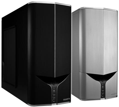
POSEIDON 310 - Computer Case GIGABYTE - Free user manual and instructions
Find the device manual for free POSEIDON 310 GIGABYTE in PDF.

| Product Type | Mid Tower Computer Case |
| Brand | GIGABYTE |
| Model | POSEIDON 310 |
| Supported Form Factors | ATX, Micro ATX, Flex ATX |
| Dimensions (W × H × D) | 200 × 440 × 505 mm |
| Net Weight | 8.8 kg |
| Chassis Material | SECC Steel 0.7 mm |
| Front Panel Material | Aluminum |
| Side Panel | Interchangeable: transparent or ventilated mesh |
| External 5.25" Bays | 5 |
| External 3.5" Bays | 2 |
| Internal 3.5" Bays | 3 |
| Expansion Slots | 7 |
| Included Fans | 1 x 120 mm (front) + 1 x 120 mm (rear), silent |
| Front I/O Ports | 2 × USB 2.0, 1 × IEEE 1394 (FireWire), 1 × Audio (HD & AC'97) |
| Power Supply | Not included, standard ATX location |
| Liquid Cooling Support | Yes, compatible with GIGABYTE 3D Galaxy and most Watercooling systems |
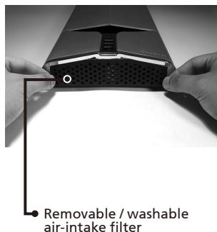
| Main Features | Tool-free installation, internal cable management, removable and washable air filter, LED lighting, anti-slip pads |
| Included Accessories | Screws, standoffs, cable ties, magnetic ring, anti-dust cloth |
| Safety | Wear gloves during assembly; check connector pinout before plugging |
| Maintenance and Cleaning | Clean the air filter regularly with soapy water; vacuum dust from inside |
| Warranty | See manual for exclusions (misuse, modification, etc.) |
Frequently Asked Questions - POSEIDON 310 GIGABYTE
User questions about POSEIDON 310 GIGABYTE
0 question about this device. Answer the ones you know or ask your own.
Ask a new question about this device
Download the instructions for your Computer Case in PDF format for free! Find your manual POSEIDON 310 - GIGABYTE and take your electronic device back in hand. On this page are published all the documents necessary for the use of your device. POSEIDON 310 by GIGABYTE.
USER MANUAL POSEIDON 310 GIGABYTE
English User's Manual
GZ-AA3CB-SJS/SJB
Thank you for purchasing GIGABYTE Tech. thermal product. GIGABYTE Tech. is dedicated to the integration of casing water/air-cooling solution technology to provide users with the most optimal solution for thermal dissipation. For further information and specifications of the "Poseidon" series, please visit GIGABYTE Tech. website. (http://www.gigabyte.com.tw)
The following are not covered by the warranty:
- Using the product incorrectly or in a manner other than the designed purpose.
- Nonobservance of the proper operation provided
- Malfunction due to interference from other devices
- Unapproved modification of the product
- Consequential damage to other devices due to the product's fault.
- Malfunction arising from natural hazards, e.g. earthquake, lightning, fire, and floods.
- The product's warranty label has been removed or damaged.
- The devices inside, including power supply, hard disk, CD-ROM drive, motherboard, ventilator, etc, are not detached from the casing prior to transportation of the computer system, resulting in damage to the casing or other computer-related devices.
- Any loss/damage caused by failure to follow the installation process with in the user manual.

CAUTION
Failure to wear gloves during installation of computer products may cause bodily harm or damage to your devices. Incorrect connector installation may possibly burn out the motherboard and other components. Be sure to observe the instructions in installation manual.
Table of Contents
- Components Introduction 3
1-1 Casing's Internal Structure 4
1-2 Front, Rear, and Left Side Panel Structure 5
1.3 Removal of Side and Front Panel 5
- Features 6
- Specifications 7
4.Installation Instruction 8
4-1 Installation of Power Supply 8
4-2 Installation of Motherboard 8
4-3 Installation of Add-on Card 9
4-4 Installation of Front Multi-Media I/O port 10
4-5 Connection of Fan Power Cables 11
4-6 Installation of 5.25" Front Device Bay 11
4-7 Installation of 3.5" Front Device Bay 12
4-8 Installation of 3.5" Internal Device Bay 12
4-9 Foot Supports 13
4-10 Liquid Cooling System Support 13
4-11RecommendedCoolingProducts 14
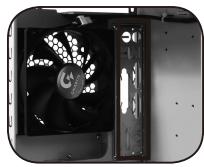
1.Components Introduction
1-1 Casing's Internal Structure
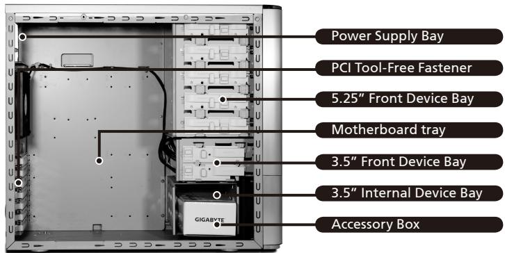
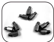
Accessory Box (Refer to the figures below for the attachments in the accessory box)
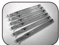
SecuringRunnerx6
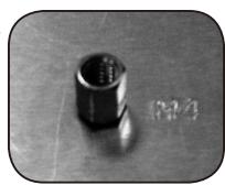
Copper Stand Off x 9
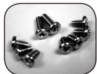
Motherboard Securing Screw x 9
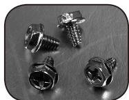
Power Supply Securing Screw x 4
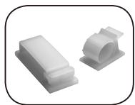
Large Wire Clamp x 2
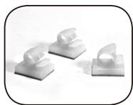
Mini Wire Clamp x 3
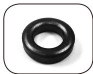
Magnet Ring x 1
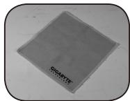
Dust Remover Cloth
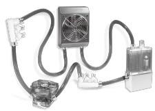
Front Cable Kit (Refer to the figures below for the cable connectors)
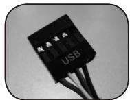
USB 2.0
Audio Set (HD & AC'97)
IEEE1394 (Multi-connectors)
Front Light 4-Pin Power Connector
3-Pin Fan Connector

Power SW/Speaker Connector
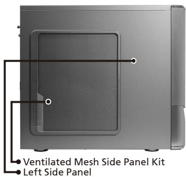
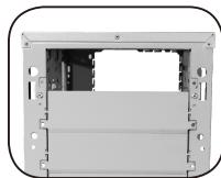
1-2 Front, Rear, and Left Side Panel Structure a) Left Side Panel b) Front Panel
c) Rear Panel
d) Bottom Panel
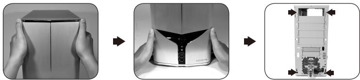
1-3 Removal of Side and Front Panels 1-3.1 To remove side panels:
1-3.1a Remove the 4 thumb screws at the rear of the side panel, and detach the side panels.
1-3.2 To remove front panel:
1-3.2a Remove the left and right side panels, release the 4 clamps that hold the front panel onto the chassis.
2.Feature
-High Quality Design
Innovative sleek dual-tone design coupled with sophisticated yet simple, precise workmanship.
Illuminated and atmospherically-soothing backlight for a post-modern classy impression.
Removable / washable air-intake filter.
-Complete Support
Complete front panel multi-media support, include 2 x USB 2.0, 1 x IEEE1394, 1 x audio set (HD & AC97)
Full Support of Gigabyte Tech. thermal solution LCS and Air cooling products lines Support ATX / Micro ATX / Flex ATX motherboard.
-Integration of Cooling Technology
Intergrated Ventilated Mesh / transparent side panel.
- Convenience of assembly
Internal Cable Management - provides users with a clean assembly environment.
Tool-free installation design.
3. Specifications
Model GZ-AA3CB-SJS/SJB
Case Type Middle Tower
Size 200 x 440 x 505mm (W x H x D)
Front Bezel Material Aluminum
Color Silver or Black
Side panel Interchangeable transparent / ventilated-mesh side panel
Body material 0.7mm SECC
Net weight 8.8 KG
5.25" drive bay (External) 5
3.5 drive bay (External) 2
3.5 drive bay (Internal) 3
Expansion slots 7
Form factor ATX / Micro ATX / Flex ATX
System Fan (front) One 120mm silent fan
System Fan (rear) One 120mm silent fan
I/O Ports USB2.0 x 2/IEB x1 (HD-AC'97)
4.Installation Instruction

Please follow the reference sections in order for installation
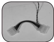
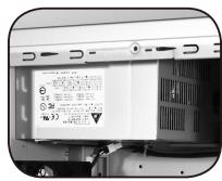
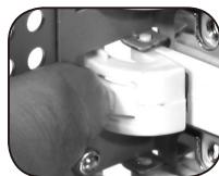
4-1 Installation of Power Supply
To facilitate the installation, it is recommended to place
the chassis upright on the table.
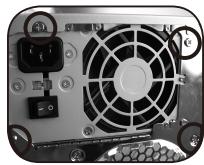
Required Tools: Power supply securing screw x 4; Cross screwdriver.
4-1.1 Remove side panel (see step 1-3.1 on page 5).
Place the power supply into the power
supply bay.
4-1.2 Use the 4 x securing screws to secure the
power supply to the rear of the chassis.
4-2 Installation of Motherboard
The Poseidon 310 can support ATX / Micro ATX / Flex-ATX
motherboards. Please confirm the dimension and specifications of the motherboard before installation.
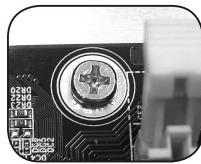
Required Tools: Cross screwdriver, Copper stand offs x 9
and Motherboard screws x 9.
4-2.1 According to the motherboard specifications,
select the proper screw holes. First screw the
copper stand offs into the corresponding
holes of the chassis.
4-2.2 Install the motherboard rear I/O panel
(supplied by the motherboard manufacturer).
4-2.3 Secure the motherboard with the securing screws (Please refer to your motherboard manual to check what type of motherboard you have).
| Motherboard | Code name | Motherboard screws | Case copper post |
| ATX | A1-A9 | 9 | 9 |
| Micro ATX | U1-U9 | 9 | 9 |
| Flex ATX | F1-F6 | 6 | 6 |
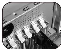
4-3 Installation of Add-on Card
The Poseidon 310 does not require any tools for installation of add-on cards, e.g. Graphics card and network card.
Required Tools: None
4-3.1 Unlock the corresponding PCI tool-free fastener by pushing it downwards.
4-3.2 Lift the fastener upwards and remove the internally attached dust-proof PCI cover.
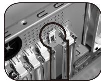
4-3.3 Insert the add-on card into the expansion slot and then lock the PCI tool-free fastener.
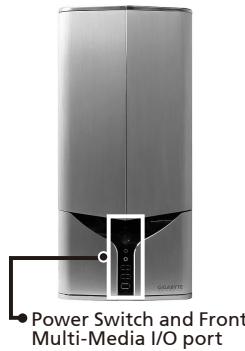
4-4 Installation of Front Multi-Media I/O port

WARNING
Incorrect connection of the slots can cause the motherboard to malfunction or completely destroy the motherboard. Please read the manual carefully in the installation as incorrect installations or connection causing faults will void your warranty.
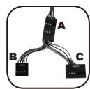
The front panel consists of:
(1) 2 × USB 2.0, 1 × IEEE 1394 and 1 × Audio Set (HD & AC'97)
(2) Basic casing power switch control cable kit.
Required Tools: None

Please refer to the instructions supplied by the motherboard manufacturer and make sure the correct type of connector is used prior to installation.
(1) 2 × USB 2.0, 1 × IEEE 1394 and 1 × Audio Set (HD & AC'97)
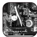
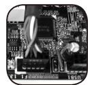
4-4.1 Insert the USB 2.0 connectors into the corresponding socket on the motherboard.
USB 2.0 connector
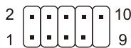
| Pin | Definition | Pin | Definition |
| 1 | Power | 6 | USB Dy+ |
| 2 | Power | 7 | GND |
| 3 | USB Dx- | 8 | GND |
| 4 | USB Dy- | 9 | |
| 5 | USB Dx+ | 10 | USB Over current |
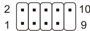
4-4.2 Insert the IEEE 1394 connector into the corresponding socket on the motherboard.
IEEE 1394 connector A
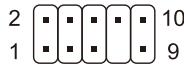
| Pin | Definition | Pin | Definition |
| 1 | TPA+ | 6 | TPB- |
| 2 | TPA- | 7 | |
| 3 | GND | 8 | +12V |
| 4 | GND | 9 | +12V |
| 5 | TPB+ | 10 | GND |
IEEE 1394 connector B
| Pin | Definition | Pin | Definition |
| 1 | TPA+ | 6 | TPB- |
| 2 | TPA- | 7 | +12V |
| 3 | GND | 8 | +12V |
| 4 | GND | 9 | |
| 5 | TPB+ | 10 | GND |
IEEE 1394 connector C
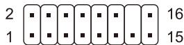
| Pin | Definition | Pin | Definition |
| 1 | +12V | 9 | +12V |
| 2 | +12V | 10 | +12V |
| 3 | TPA+ | 11 | TPA1+ |
| 4 | TPA- | 12 | TPA1- |
| 5 | GND | 13 | GND |
| 6 | GND | 14 | |
| 7 | TPB+ | 15 | TPB1+ |
| 8 | TPB- | 16 | TPB1- |
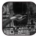
4-4.3 Insert the Audio connector into the corresponding socket on the motherboard.
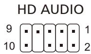
| Pin | Definition | Pin | Definition |
| 1 | MIC2_L | 6 | FSENSE1 |
| 2 | GND | 7 | FAUDIO JD |
| 3 | MIC2_R | 8 | |
| 4 | -ACZ_DET | 9 | LINE2_L |
| 5 | LINE2_R | 10 | FSENSE2 |
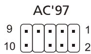
| Pin | Definition | Pin | Definition |
| 1 | MIC | 6 | NC |
| 2 | GND | 7 | NC |
| 3 | MIC Power | 8 | |
| 4 | NC | 9 | Line Out(L) |
| 5 | Line Out(R) | 10 | NC |
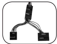
(2) Basic casing power switch control cable kit.
Follow the connectors list below for installation (see figure below)

| Connector | Color |
| Speaker | Yellow(+) / Black(-) |
| Power SW | Orange(+) / White(-) |
| HDD LED | Red(+) / White(-) |

Different motherboards have different installation areas and specifications, screw holes and connectors. For detailed instructions, please refer to the motherboard user manual supplied by the motherboard manufacturer.
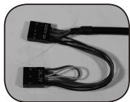
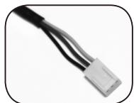
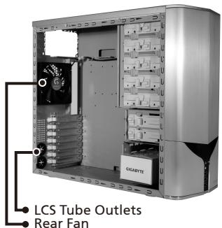
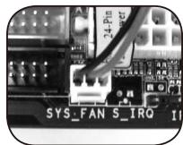
4-5 Connection of Fan Power Cables
The Poseidon 310 has one 12cm silent cooling fan in the front and one in the rear. This case includes internal connectors that connects the front and rear fans making it a single 3-pin connector. Required Tools: None
4-5.1 Plug the 3-pin connector into the corresponding system fan socket on the motherboard.
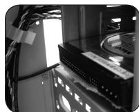
4-6 Installation of 5.25" Front Device Bay
4-6.1 Detach the front panel (see step 1-3.2 on page 5) and remove the mesh drive rail from the front panel.
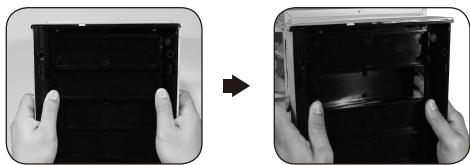
4-6.2 Remove the front EMI plate and attach the front panel onto the chassis.
4-6.3 Slide the 5.25" device into the drive bay from the front of the chassis.
4-6.4 Secure the 5.25" device with the internal latch. Refer to the figure for installation procedure.

4-7 Installation of 3.5" Front Device Bay
Installation of 3.5'' front device is the same as 5.25'' front devices, please refer to step 4-6.
4-8 Installation of 3.5" Internal Device Bay
The Poseidon 310 provides built-in bays to accommodate up to 3 hard disc drives. The built-in HDD requires securing runners, which can be found in the accessory box.
Required tools: Securing runners (2 per hard disc drive)
4-8.1 Fit the securing runners on both sides of the HDD and slide the HDD into the internal drive bay.
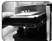

Additional HDD can be installed in the 3.5'' front device bay. Slide in the HDD and lock the internal latch to secure the HDD.
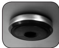
4-9 Foot Supports
The Poseidon 310 is supplied with four high-end skid-proof foot supports for ensuring the casing is firmly seated on the holding surface.
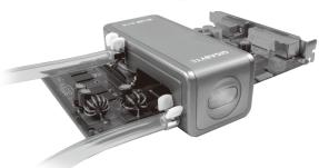
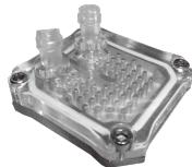
4-10 Liquid Cooling System Support
The Poseidon 310 casing can fully support the GIGABYTE 3D Galaxy Liquid Cooling System (it also supports majority of the liquid cooling systems available commercially). While installing the liquid cooling system, please refer to the manual provided with the liquid cooling system.
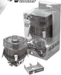
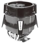
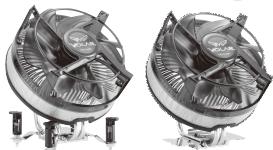
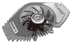
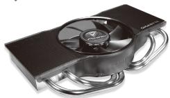
4-11 Recommended Cooling Products
The Poseidon 310 is recommended to be used with GIGABYTE Cooling products.


- Table of Contents
- 1.Components Introduction
- 1-1 Casing's Internal Structure
- 1-2 Front, Rear, and Left Side Panel Structure a) Left Side Panel b) Front Panel
- 1-3 Removal of Side and Front Panels 1-3.1 To remove side panels:
- 1-3.2 To remove front panel:
- 2.Feature
- -High Quality Design
- -Complete Support
- -Integration of Cooling Technology
- - Convenience of assembly
- Specifications
- 4.Installation Instruction
- 4-1 Installation of Power Supply
- 4-2 Installation of Motherboard
- 4-3 Installation of Add-on Card
- 4-4 Installation of Front Multi-Media I/O port
- 2 × USB 2.0, 1 × IEEE 1394 and 1 × Audio Set (HD & AC'97)
- Basic casing power switch control cable kit.
- 4-5 Connection of Fan Power Cables
- 4-6 Installation of 5.25" Front Device Bay
- 4-7 Installation of 3.5" Front Device Bay
- 4-8 Installation of 3.5" Internal Device Bay
- 4-9 Foot Supports
- 4-10 Liquid Cooling System Support
- 4-11 Recommended Cooling Products
Brand : GIGABYTE
Model : POSEIDON 310
Category : Computer Case