
GZ-X3 - Computer Case GIGABYTE - Free user manual and instructions
Find the device manual for free GZ-X3 GIGABYTE in PDF.


| Product Type | Computer Case |
| Brand | GIGABYTE |
| Model | GZ-X3 |
| Form Factor | Mid Tower |
| Motherboard Compatibility | ATX, Micro ATX, Mini ITX |
| Dimensions (W x H x D) | 180 mm x 450 mm x 400 mm |
| Weight | 5.5 kg |
| Front Panel Ports | 2 x USB 2.0, 1 x IEEE 1394 (optional), 1 x Audio Jacks (HD Audio/AC97) |
| Expansion Slots | 7 |
| Drive Bays | 3x 5.25 inch external, 4x 3.5 inch internal |
| Cooling System | Optional front intake fan (120mm), rear fan mount |
| Power Supply | Not included, standard ATX |
| Material | Steel chassis, plastic front bezel |
| Tool-less Installation | Available for drive bays and expansion cards |
| Security | Side panel lock (optional featured) |
| Warranty | 1 year limited warranty (typical) |
Frequently Asked Questions - GZ-X3 GIGABYTE
User questions about GZ-X3 GIGABYTE
0 question about this device. Answer the ones you know or ask your own.
Ask a new question about this device
Download the instructions for your Computer Case in PDF format for free! Find your manual GZ-X3 - GIGABYTE and take your electronic device back in hand. On this page are published all the documents necessary for the use of your device. GZ-X3 by GIGABYTE.
USER MANUAL GZ-X3 GIGABYTE
User Guide For GZ-X Series

Optional remarks based on models available in your territory:
-
The IEEE1394 situated on the front panel is optional.
-
Tool-less illustrations indicated pertain to models with tool-less options
- Front intake system fan indicated are also specific to certain models
Installation of Front Multi-Media I/O Ports

Incorrect connector installation may possibly burn out the motherboard and other components. Be sure to observe the instructions on installation manual. Any loss caused by nonobservance of the proper operation provided is not covered by the warranty.
The connector or socket varies with different motherboards. For detailed instructions, please refer to the instructions provided by the motherboard manufacturer.
The Front Panel consists of
(1)2xUSB 2.0 (2)1xIEEE 1394 (Optional) (3)1xAudio Jacks 4)Power SW / Reset SW / LED connectors
1 2xUSB 2.0
Insert the USB 2.0 connector into the corresponding sockets on the motherboard. (Please double check the layout on motherboard user manual)
USB 2.0 connector
2 10
1 9

2 1xIEEE 1394 (Optional)
Insert the IEEE 1394 connector into the corresponding socket on the motherboard. There is a converter connector, please refer to the instructions supplied by the motherboard manufacturer and make sure the correct type of connector prior to installation.
IEEE 1394 connector A
2 10
1 9
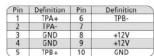
IEEE 1394 connector B
2 10
1 9

IEEE 1394 connector C
2 | • | • | • | • | • | • | 16
1 | • | • | • | • | • | • | 15

3 1xAudio Jacks
Insert the audio connector into the corresponding socket on the motherboard. There are HD audio and AC97 connector, please refer to the motherboard user manual.


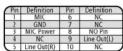

Be sure that different motherboards may have different installation positions. For detailed instructions, please refer to the instructions supplied by the motherboard manufacture
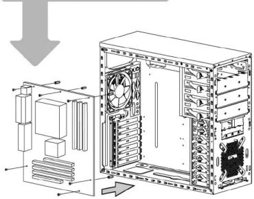
Hardware Installation
1 Motherboard Installation
2 Add-on card Installation

flowchart
graph TD
    A["1: Fan"] --> B["2: Computer tower"]
    B --> C["3: Display panel"]
    C --> D["4: Display unit"]
    D --> E["5: Lock"]
    E --> F["6: Server rack with lock"]
    style A fill:#f9f,stroke:#333
    style B fill:#ccf,stroke:#333
    style C fill:#cfc,stroke:#333
    style D fill:#fcc,stroke:#333
    style E fill:#cff,stroke:#333
    style F fill:#ffc,stroke:#333


Brand : GIGABYTE
Model : GZ-X3
Category : Computer Case