
POSEIDON - Computer Case GIGABYTE - Free user manual and instructions
Find the device manual for free POSEIDON GIGABYTE in PDF.

| Product Type | Computer Case |
| Brand | GIGABYTE |
| Model | POSEIDON (GZ-XA1CA-STB/GZ-XA1CA-STS) |
| Form Factor | Mid-Tower |
| Dimensions (L x H x D) | 200 x 440 x 495 mm |
| Net Weight | 8 kg |
| Front Panel Material | Aluminum |
| Body Material | SECC (galvanized steel) |
| Color | Silver or Black |
| Side Panel | Elegant ventilated (factory) / Transparent (optional) |
| External 5.25" Bays | 5 |
| External 3.5" Bays | 1 |
| Internal 3.5" Bays | 3 |
| Expansion Slots | 7 (with tool-free PCI fixation) |
| Compatible Motherboard Form Factors | ATX, Micro ATX |
| Front Fan | 1 x 120 mm (silent) |
| Rear Fan | 1 x 120 mm (silent, blue LED) |
| Front I/O Ports | USB 2.0 x2, IEEE 1394 x1, HD Audio x1 |
| Water Cooling Support | Yes (compatible with Gigabyte 3D Galaxy and others) |
| Power Supply Included | No (standard top mount) |
| Main Features | Customizable light projector with blue/white LED, aluminum design, anti-slip feet, internal cable management, tool-free assembly |
| Maintenance and Cleaning | Clean with a soft, dry cloth. Do not use abrasive or liquid products. |
| Safety | Wear gloves during installation. Connect connectors correctly to avoid damaging the motherboard. |
| Spare Parts and Repairability | Screws, slides, connectors included. Parts available on GIGABYTE website. |
Frequently Asked Questions - POSEIDON GIGABYTE
User questions about POSEIDON GIGABYTE
0 question about this device. Answer the ones you know or ask your own.
Ask a new question about this device
Download the instructions for your Computer Case in PDF format for free! Find your manual POSEIDON - GIGABYTE and take your electronic device back in hand. On this page are published all the documents necessary for the use of your device. POSEIDON by GIGABYTE.
USER MANUAL POSEIDON GIGABYTE
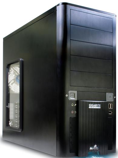
The chassis of Gigabyte Poseidon series is made by high-end Aluminum bezel design with dual 12cm (front and rear) silent fans to offer the best ventilation for the system. The internal cable management and tool-free design provide users with easier installation procedures and computer system management. Using the patent 2 colors front projector light with changeable LED colors (blue/white) and the see-through/air inlet side panel, users can customize their own style. For further information and specifications of the Poseidon series, please download them from Gigabyte's website.
The following are not covered by the warranty
- Incorrect use or use of the product for any purpose other than its intended use.
- Nonobservance of the proper operation provided. (e.g. over-clocking)
- Malfunction due to interference from other devices.
- Unauthorized modification of the product.
- Consequential damage to other objects due to the product's fault.
- Malfunction arising from casualties (earthquake, thunder, fire, or flood).
- The warranty label of the product has been removed or damaged.
- The devices inside, including power supply, hard disk, CD-ROM drive, motherboard, ventilator, etc, are not detached from the casing prior to the transportation of the computer product, resulting in damage to the chassis or computer-related devices.
- Any loss arising from nonobservance of the proper operation provided is not covered by the warranty.

Caution
Failure to wear gloves during installation of computer products may cause damage to personnel and devices. Incorrect connector installation may possibly burn out the motherboard and other components. Be sure to observe the instructions on installation in the manual.
Contents
1 Components Introduction 4
1-1 Chassis's Internal Structure 4
1-2 Side Panel Introduction 6
1-3 Front and Rear Panel Instruction 7
2 Features. 8
3 Specification 8
4 Installation Instruction 9
4-1 Installation of Power Supply 9
4-2 Installation of Motherboard 9
4-3 Installation of Interface Card 10
4-4 Installation of Front I/O Panel 11
4-5 Chassis's Internal Structure 12
4-6 Installation of 5.25" Front Device Bay 13
4-7 Installation of 3.5" Front Device Bay 13
4-8 Installation of Built-in HDD (Hard Disc Drive) 14
4-9 Power cable installation of the front projector light. 14
4-10 DIY Front Bracket of Projector Light 15
4-11 Foot Stand Instruction 16
4-12 Liquid Cooling System Support 17
4-13 Recommended Air Cooling 17
1 Components Introduction
1-1 Chassis's Internal Structure
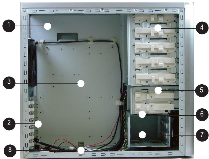
Power supply
3 Motherboard/panel card
PCI tool-free fastener
4 5.25" Front device bay
5 3.5" Floppy
6
Build-in hard disk
7 Accessory box
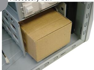
(Refer to the right figures for the attachments in the tool enclosure)
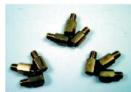
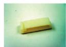
a. Standoff x 9
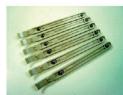
b. Securing runner x 6
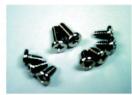
c. Motherboard securing screw x 9
d. Wire clamp x 1
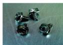
e. Power supply securing screw x 4
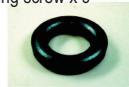
f. Magnet ring x 1
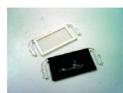
g. DIY transparent projector panel x 1 (Equipped with Poseidon at shipment)
8 Front cable kit
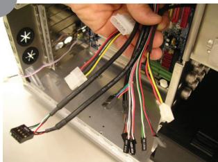
(Refer to the right figures for the cable connectors)
a. USB 2.0
b. HD AUDIO
c.IEEE1394
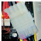
d. Power supply of the front projector light

e. Power supply of front and rear fans
f. Basic chassis power switch control cable kit

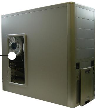
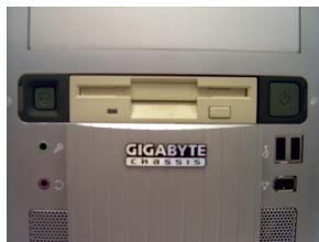
Side Panel Introduction
See-through side panel installation complete figure (A-1)
(Factory default: vent side panel)
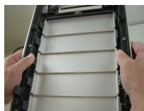
1-2-1 To replace the See-through side panel:
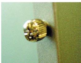
Step 1: Release 4 screws at the rear of the side panel to remove the panel.
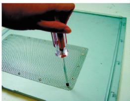
Step 2: Remove the factory default perforated side panel.
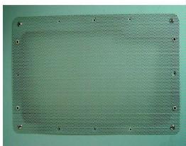
Step 3: Draw out the perforated side panel.
Step 4: Place and screw the See-through side panel properly to complete the installation procedure.
1-3
Front and Rear Panel Instruction
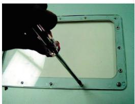
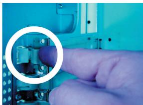
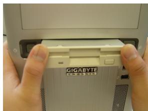
1-3-1 To remove front panel:
Step 1: Remove the left and right side panels (see Step 1-2-1 on Page 6) and slightly pull out both sides of the upper (see, Figure a) and lower (see Figure b) fasteners (see Figure c).
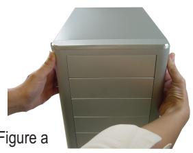
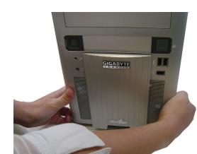
Figure b
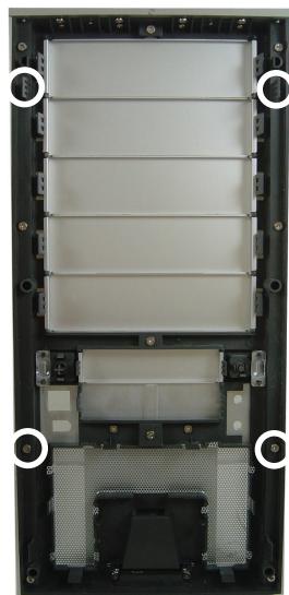
Figure c
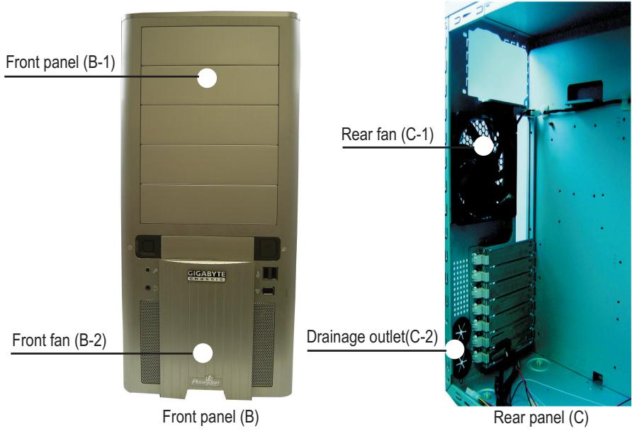
2 Features
- High quality design -
(Patent Pending)Customizable light beam projector w/ changeable LED color (Blue/White) Hign-end Aluminum bezel design Skidproof & shockproof foot stand
- Integration of cooling technology -
(Patent pending)Integrated side panel (See-through & elegant vent design) Quad-ways front air-inlet design
- Complete support -
Front bezel I/O (USBx2,IEEE1394x1, HD audiox1)
Dual 12cm silent & shockproof fan (Rear fan w/ LED)
Supports water cooling systems
- Convenience of assembly -
Internal Cable Management - provide users clean assembly environment Tool-less design & Hassle-Free Assembly
3 Specification
| Model : GZ-XA1CA-STB/GZ-XA1CA-STS |
| Case Type : Mid-Tower |
| Dimension : 200 x 440 x 495mm (W x H x D) |
| Front bezel Material : Aluminum |
| Color : Silver / Black |
| Side Panel : Elegant Vent Design |
| Body Material : SECC |
| Net Weight : 8 kg |
| 5.25" drive bay (External) : 5 |
| 3.5" drive bay (External) : 1 |
| 3.5" drive bay (Internal) : 3 |
| Expansion Slot : 7 |
| Compatible MB : ATX / Micro ATX |
| System Fan (front) : 120 mm silent fan x1 |
| System Fan (rear) : 120 mm silent fan w/ blue LEDs x1 |
| I / O Ports : USB2.0 x2 / IEEE 1394 x1 / HD audio x1 set |
| Optional Thermal Solutions : |
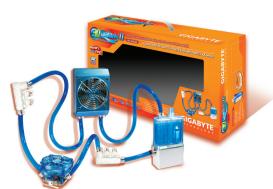
| GIGABYTE Liquid Cooling - 3D Galaxy Series |
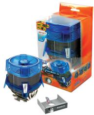
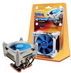
| GIGABYTE Air Cooling - G-Power Lite Series |

Installation Instruction

Please follow the reference sections for installation.
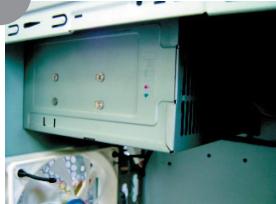
4-1 Installation of Power Supply
To facilitate the installation, it is recommended to place the Poseidon chassis upright on the table. Required tool: Power supply securing screw x 4.
4-1-1 Please remove the left side panel before placing the power supply into the chassis.
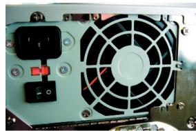
4-1-2 Use screws to secure the power supply from the rear side.
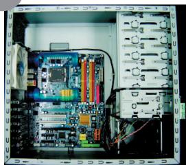
4-2 Installation of Motherboard
The Poseidon is compatible with the ATX/Micro ATX motherboard. Please confirm the dimension and specifications of the motherboard before installation.
Required tool: motherboard standoffs x 9 and securing screws x 9
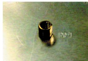
4-2-1 According to motherboard specifications, select proper screw holes, engage the standoffs into the corresponding holes of the chassis.
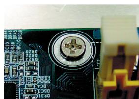
4-2-2 Secure the motherboard with securing screws.
| Motherboard | Code | Motherboard securing screw | Standoffs |
| ATX | A1-A9 | 9 | 9 |
| MINI ATX | M1-M9 | 9 | 9 |
| MICRO ATX | U1-U9 | 9 | 9 |
| FLEX ATX | F1-F6 | 6 | 6 |

Select proper rear I/O panel of the motherboard (typically supplied by motherboard manufactures).
4-3 Installation of Interface Card
The Poseidon supports tool-free installation of interface cards, e.g. Graphic card and Network Card, etc.
Required tool: None
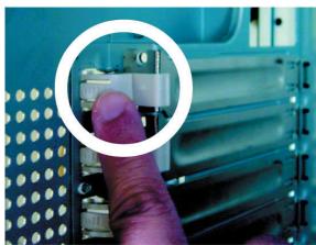
4-3-1 Unlock securing fasteners of the PCI socket; push the fastener downwards first.
4-3-2 And then, push the fastener upwards.
4-3-3 Remove the internally attached dust-proof PCI cover.
4-3-4 Insert the interface card into the expansion slot with care.

Make sure all interface cards are fully seated in the corresponding slots.
4-4
Installation of Front I/O Panel

CAUTION
Incorrect connector installation may possibly burn out the motherboard and other components. Be sure to observe the instructions on installation in the manual. Any loss arising from nonobservance of the proper operation provided is not covered by the warranty.
Different motherboards may have different installation positions. For detailed instructions, please refer to the instructions supplied by the motherboard manufacturer.
The front panel consists of (1) Two USB 2.0 ports, one IEEE 1394, and one High Definition Audio connector.
(2) Basic chassis power switch control cable kit
Required tool: None
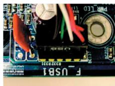
(1) Two USB 2.0 ports, one IEEE 1394, and one High Definition Audio connector.
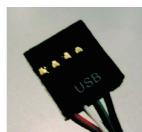
4-4-1 Insert the USB2.0 connector into the corresponding socket on the motherboard.
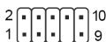
USB 2.0 Connector
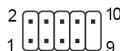
| Pin | Definition | Pin | Definition |
| 1 | Power | 6 | USB Dy+ |
| 2 | Power | 7 | GND |
| 3 | USB Dx- | 8 | GND |
| 4 | USB Dy- | 9 | |
| 5 | USB Dx+ | 10 | USB Over Current |
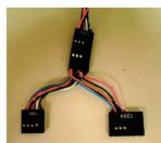
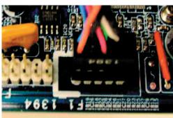
4-4-2 Insert the IEEE 1394 connector into the corresponding socket on the motherboard.

Please refer to the instructions supplied by the motherboard manufacturer and make sure the correct type of connector prior to installation.
a. IEEE1394 Connector A
| Pin | Definition | Pin | Definition |
| 1 | TPA+ | 6 | TPB- |
| 2 | TPA- | 7 | |
| 3 | GND | 8 | +12V |
| 4 | GND | 9 | +12V |
| 5 | TPB+ | 10 | GND |
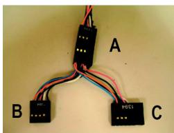
b. IEEE1394 Connector B
| Pin | Definition | Pin | Definition |
| 1 | TPA+ | 6 | TPB- |
| 2 | TPA- | 7 | +12V |
| 3 | GND | 8 | +12V |
| 4 | GND | 9 | |
| 5 | TPB+ | 10 | GND |
c. IEEE1394 Connector C
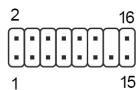
| Pin | Definition | Pin | Definition |
| 1 | +12V | 9 | +12V |
| 2 | +12V | 10 | +12V |
| 3 | TPA+ | 11 | TPA1+ |
| 4 | TPA- | 12 | TPA1- |
| 5 | GND | 13 | GND |
| 6 | GND | 14 | |
| 7 | TPB+ | 15 | TPB1+ |
| 8 | TPB- | 16 | TPB1- |
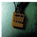
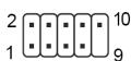
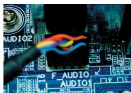
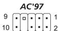
4-4-3 Attach the HD Audio connector to the pin located on the motherboard.
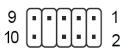
| Pin | Definition |
| 1 | MIC2_L |
| 2 | GND |
| 3 | MIC2_R |
| 4 | -ACZ_DET |
| 5 | Line2_R |
| 6 | FSENSE1 |
| 7 | FAUDIO_JD |
| 8 | No Pin |
| 9 | LINE2_L |
| 10 | FSENSE2 |
| Pin | Definition | Pin | Definition |
| 1 | MIC | 6 | NC |
| 2 | GND | 7 | NC |
| 3 | MIC Power | 8 | NO Pin |
| 4 | NC | 9 | Line Out (L) |
| 5 | Line Out (R) | 10 | NC |
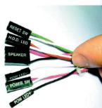
(2) Basic chassis power switch control cable kit.
Follow the connectors listed below for installation (see the figure below).
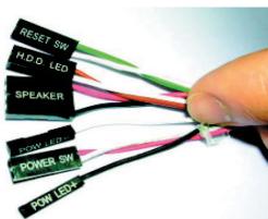
| Connector | Color |
| Speaker | Yellow(+) / Black(-) |
| Reset SW | Blue(+) / White(-) |
| Power SW | Orange(+) / White(-) |
| POW LED+ | Green |
| POW LED- | White |
| H.D.D. LED | Red(+) / White(-) |

Be sure to remember that different motherboards may have different installation positions. For detailed instructions, please refer to the instructions supplied by the motherboard manufacturer.
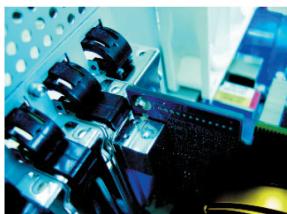
4-5 Chassis's Internal Structure
The Poseidonis equipped with dual 12cm silent fans (front and rear). Required tool: None
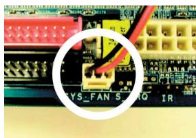
4-5-1 Plug the front fan 3-pin power connector into the fan power connector of the motherboard system.
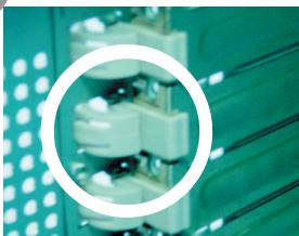
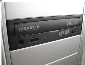
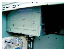
4-6
Installation of 5.25" Front Device Bay
The installation of 5.25" CD-ROM is also intended for installation of general 5.25" front device bay. Required tool: None
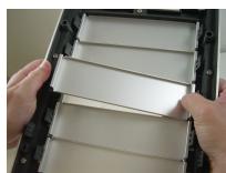
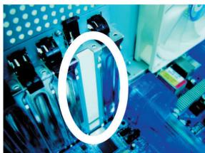
4-6-1 Remove the front panel (see Step 1-3-1 on Page 7) and take off the 5.25'' internal metallic panel.
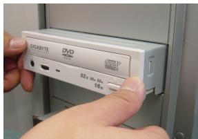
4-6-2 Slide the 5.25" CD-ROM into the drive.
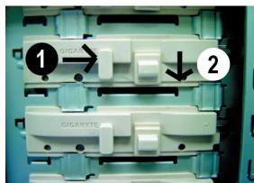
4-6-3 Refer to the installation order illustrated in the left figure and secure the 5.25" CD-ROM by controlling the latch. (Reverse steps for disassembly)
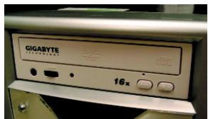
4-6-4 Installation completed.
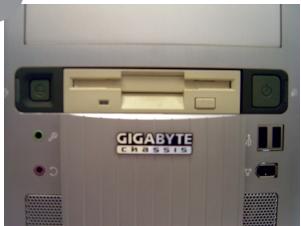
4-7
Installation of 3.5" Front Device Bay
The installation of 3.5" floppy disc drive intended for installation of general 3.5" front device bay Required tool: None
4-7-1 Remove the front panel (same as Step 4-6-1).
4-7-2 Slide the 3.5" floppy disc drive into the drive bay.
4-7-3 Refer to the installation order illustrated in the left figure and secure the 3.5'' floppy disc drive by controlling the latch. (Reverse steps for disassembly)
4-7-4 Installation completed.
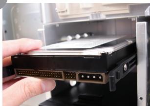
4-8 Installation of Built-in HDD (Hard Disc Drive)
The Poseidon built-in HD drive bay can be installed with up to 3 HDDs. The built-in HDD requires securing runners, which are located in the accessory box below.
Required tools: 6 securing runners (in the accessory box)
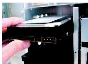
4-8-1 Use the runners installed on both sides of the HDD evenly and slide the HDD into the hard disk drive bay.
4-9 Power cable installation of the front projector light
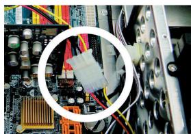
4-9-1 Plug the front projector light 4-pin power cable into the 4-pin connector on the motherboard.
4-10
DIY Front Bracket of Projector Light
The Poseidon is provided with another transparent projector panel, which can be DIY designed and replaced with the projector bracket under front panel.
Required tool: transparent projector panel (slides and laser printer or copy machine should be provided by the user)
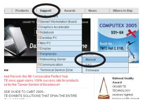
4-10-1 Please visit Gigabyte website (http:// gwebmanager1:7001/Products/Chassis/Default.aspx) to search the Poseidon series case products by file name "DIYbracket_Poseidon.doc".

Print out the slides by 1:1
(Pleases use the laser printer or copy machine)
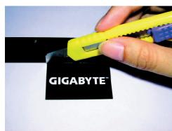
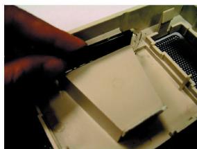
4-10-2 Trim the slide along the edge lines.
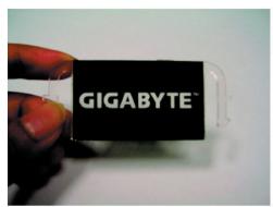
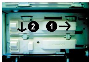
4-10-3 Post the trimmed slide onto the transparent projector panel.
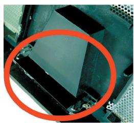
4-10-4 Remove the factory default plate located in the bottom of the front panel.
(See Figure a and Figure b)
4-10-5 Push forward to remove the factory default plate.
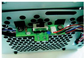
4-10-6 There is a switch for changing the color of projection lamp on the case; the right side is blue and the left side is white.

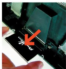
4-10-7 Place the completed transparency plate on the bottom position of the front panel and refit the front panel.
4-10-8 DIY projector installation complete figure.
4-11 Foot Stand Instruction
The Poseidon is supplied with four skid-proof foot stands for ensuring the chassis is firmly seated on the holding surface.
4-11-1 High-end skid-proof food stand.
4-12 Liquid Cooling System Support
The Poseidon series chassis can fully support the Gigabyte 3D Galaxy Liquid cooling kit (also support most of the liquid cooling systems commercially available). While installing the liquid cooling system, please consult its manual first.
4-13 Recommended Air Cooling
The Poseidon is recommended to be used with the Gigabyte Air Cooling series.


- Caution
- Contents
- Components Introduction 4
- Features. 8
- Specification 8
- Installation Instruction 9
- Components Introduction
- 1-1 Chassis's Internal Structure
- Power supply
- Motherboard/panel card
- PCI tool-free fastener
- 5.25" Front device bay
- 3.5" Floppy
- 6
- Accessory box
- Front cable kit
- Side Panel Introduction
- 1-2-1 To replace the See-through side panel:
- 1-3
- Front and Rear Panel Instruction
- 1-3-1 To remove front panel:
- Features
- - High quality design -
- - Integration of cooling technology -
- - Complete support -
- - Convenience of assembly -
- Specification
- Installation Instruction
- 4-1 Installation of Power Supply
- 4-2 Installation of Motherboard
- 4-3 Installation of Interface Card
- 4-4
- Installation of Front I/O Panel
- 4-5 Chassis's Internal Structure
- 4-6
- Installation of 5.25" Front Device Bay
- 4-7
- Installation of 3.5" Front Device Bay
- 4-8 Installation of Built-in HDD (Hard Disc Drive)
- 4-9 Power cable installation of the front projector light
- 4-10
- DIY Front Bracket of Projector Light
- 4-11 Foot Stand Instruction
- 4-12 Liquid Cooling System Support
- 4-13 Recommended Air Cooling
Brand : GIGABYTE
Model : POSEIDON
Category : Computer Case