GA-7VAX1394 - Motherboard GIGABYTE - Free user manual and instructions
Find the device manual for free GA-7VAX1394 GIGABYTE in PDF.
Download the instructions for your Motherboard in PDF format for free! Find your manual GA-7VAX1394 - GIGABYTE and take your electronic device back in hand. On this page are published all the documents necessary for the use of your device. GA-7VAX1394 by GIGABYTE.
USER MANUAL GA-7VAX1394 GIGABYTE
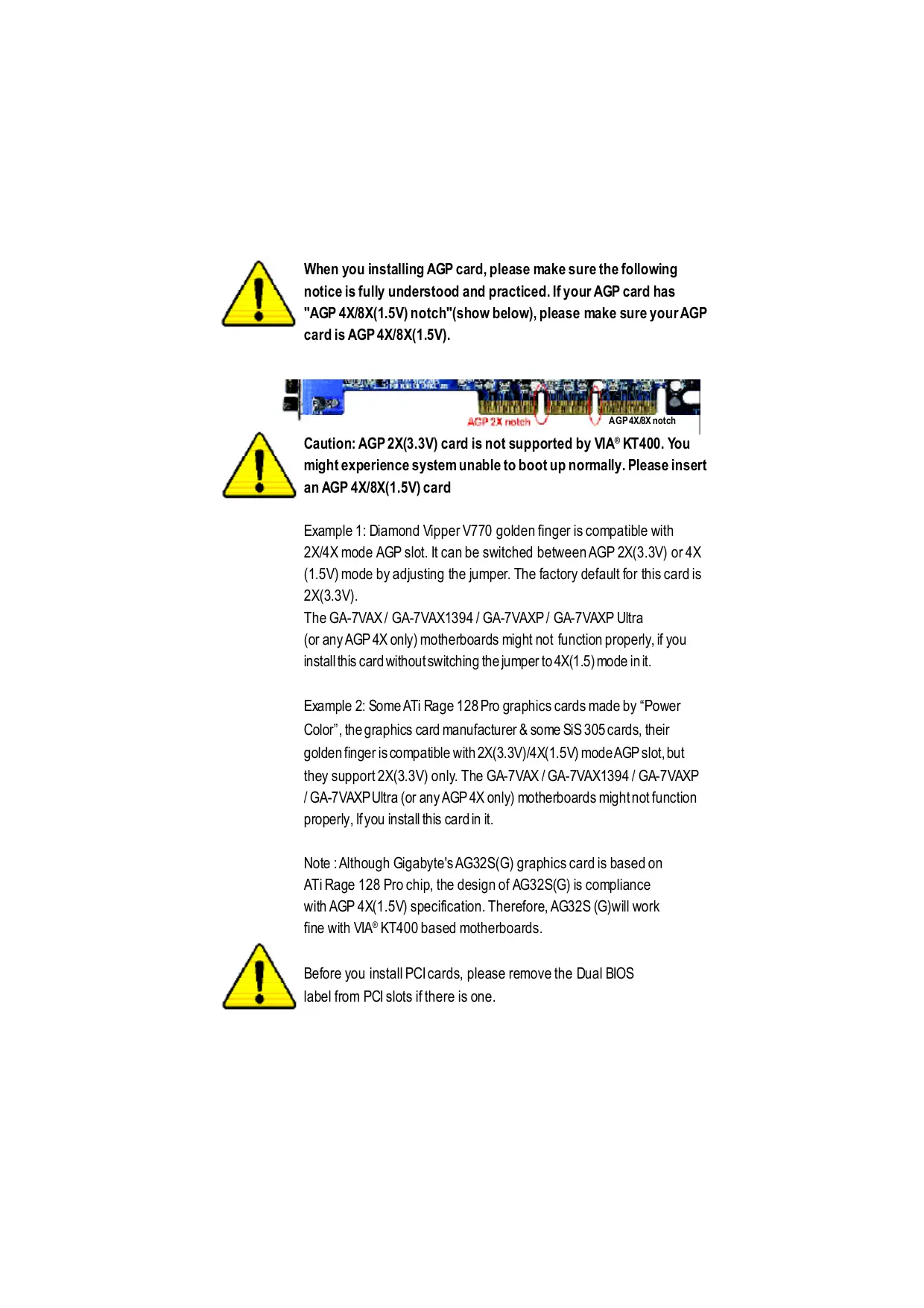
When you installing AGP card, please make sure the following notice is fully understood and practiced. If your AGP card has "AGP 4X/8X(1.5V) notch"(show below), please make sure your AGP cardis AGP 4X/8X(1.5V). ACP 2x noteh / AGP4X/ÆEX notch Caution: AGP 2X(3.3V) card is not supported by VIA® KT400. You might experience system unable to boot up normally. Please insert an AGP 4X/8X(1.5V) card Example 1: Diamond Vipper V770 golden finger is compatible with 2X/4X mode AGP slot. It can be switched between AGP 2X(3.3V) or 4X (1.5V) mode by adjusting the jumper. The factory default for this card is 2X(3.3V). The GA-7VAX/ GA-7VAX1394 / GA-7VAXP / GA-7VAXP Ultra (or any AGP 4X only) motherboards might not function propeny, if you installthis card without switching the jumper to4X(1.5) mode init. Example 2: Some ATi Rage 128 Pro graphics cards made by “Power Color”, the graphics card manufacturer & some SiS 305 cards, their golden finger is compatible with 2X(3.3V)/4X(1.5V) mode AGP slot, but they support 2X(3.3V) only. The GA-7VAX / GA-TVAX1394/ GA-7VAXP 1 GA-7VAXP Ultra (or any AGP 4X only) motherboards mightnot function properly, lfyou install this cardin it. Note : Although Gigabyte's AG32S(G) graphics card is based on ATiRage 128 Pro chip, the design of AG32S(G) is compliance With AGP 4X(1.5V) specification. Therefore, AG32S (G)will work fine with VIA® KT400 based motherboards. Before you install PCIcards, please remove the Dual BIOS label from PCI slots ifthere is one.
© The author assumes no responsibility for any errors or omissions that may appear in this document nor does the author make a commitment to update the information contained herein. © Third-party brands and names are the property of their respective owners. Please do not remove any labels on motherboard, thismay void the warranty of this motherboard. Due to rapid change in technology, some of the specifications might be out of date before publication of this booklet.
DECLARATION OF CONFORMITY
Responsible PartName: G.B.T. INC. (U.S.A.) Address: 17358 Railroad Street City of Industry, CA 91748 Phone/F ax No: (818) 854-9338/ (818) 854-9339 hereby declares that the product Product Name: Motherboard Model Num er: CA: TVAX /GA-7VAX1394 “GA-7VAXP/GA-TVAXP Ultra Conforms to the following specifications: FCC Part 15, Subpart B, Section 15.107(a) and Section 15.109 (a),Class B Digital Device Supplementary Information: This device complies with part 15 of the FCC Rules. Operation is subject to the following two conditions: (1) This device may not cause harmful and (2) this device must accept any inference received, including that may cause undesired operation. Representative Person’s Name: ERIC LU Signature: Z'ric Lu Date: December27,2002
GIGABYTE obtained of the event to validate the performance of ATi and Nvidia based graphics cards (AGP 8X) with VIA Chipset based motherboards running Microsoft operating systems. Certificates of Validation will be supplied by VIA, ATi and nVIDIA for GA-7VAXP Ultra; GA-7VAXP; GA-7VAX1394; GA-7VAX and GA-7VA that successfully passed in the AGP 8X standard validation In AGP Standards
Features Summary KT400 Series Motherboard Layout
Chapter 2 Hardware Installation Process
Chapter 4 Technical Reference
Item Checklist M1 TheKT400 Series moherboard M RAD Manual * M IDE cable x 1/ Floppy cable x 1 M 4 PortUSB Cable x 1 M IDE cable x 2* M1 Audio combo Kit x1 * M CD formotherboard driver & utility M IEEE 1394 Cable x1 ** M KT400Seresusersmanual D SPD Kit x1 M LO Shield M Quick PC Instllaïion Guide EM Motherboard SetingsLabel M SATARAID Manual * M SATA cable x 2 * OC GC-SATA Card * (Optonal) 1 (Manual ; SATAcable x1 ; Power cable x1) Computer motherboards and expansion cards contain very delicate Integrated Circuit (IC) chips. To protectthem against damage fromstai electriity, you should folow some precaufons whenever you work on your computer.
1. Unplug yourcomputer when working onthe inside.
2. Usea groundedwrist srap before handling computer components. ffyou do nothave
one, touch bothofyourhands to a safely grounded objector to a metalobject such as the power supplycase.
3. Hold component bye edges and trynotbuch he IC chips, leads or connectors, or
4. Place components on a grounded anfstañc pad or on the bag thatcame with he
componens wheneverthe components are separa&d fromthe system.
5. Ensure thatthe ATX power supply is switched offbefore you plug in or remove theATX
power connector on he motherboard. Installing the motherboard to the chassis. Ifhemotherboard has mouning holes.buttheydonttineup wih the holeson he base andthere are nosloë to atachthe spacers, do notbecome alarmed you can sil atach the spacers to he mouning holes. Justcutthe botiom portion ofthe spacers (he spacermaybe alitle hard to cutof, so be careful ofyour hands). In this way you can stllatach he motherboard b the base without worying aboutshort circuits. Someîmes you mayneed to use the plasfc springs b isolaë the screw fomthe motherboard PCBsurface, because the circuitwire may be near by he hole. Be carelul, don'tletthe screw contact anyprind circuitwite or parts on the PCB thatare near he fxing hole, ofherwise itmay damage the boardor cause boardmalfunctoning. ** FOR GA-7VAXP Ultra Only. FOR GA-7VAXP Ultra / GA-7VAXP Only. #* For GA-7VAXP Ultra / GA-7VAXP / GA-7VAX1394 Only. KT400 Series Motherboard -4-
On-BoardSound Realtek ALC650 CODEC Line Out/ 2frontspeaker Line In /2 rear speaker(by s/w switch) Mic In / center& subwoofer(by s/w switch) SPDIF Out/SPDIF In CD In /AUX In / Game port On-Board USB 2.0 Buïltin VIA VT8235 Chipset On-Board RAD * OnbardPromise PDC20276 Supports daë striping (RAID 0) or mirroring (RAD 1) Supports concurrentdualiDE controller operation Supports DE bus master operafon Displays status and error checking messages during bootup Miroringsupporis automañc background rebuilds Features LBA and Extended hterrupt 13 drive translation in contolleronboard BIOS On-Board SATA RAID * Onboard Silicon mage Si3112A Supports Disk striping (RAIDO) or DISK Mirroring (RAID1) Supports UDMA up to 150 MB/sec AIL UDMA and PIO Modes Up to 2 SATA Device ACPI and ATA/ATAP On-Board LAN Reallek RTL8100BL On-Board EEE 1394 ** VT6306 PS/2 Connector PS/2Keyboard ineriace and PS/2 Mouse interace BIOS Licensed Award BIOS, 2M bitflash ROM AddionalFeatres PS/2 Keyboard power on by password PS/2 Mouse power on External Modem wake up STR(Suspend-To-RAM) Wake on LAN(WOL) AC Recovery Poly fuse for keyboard over-curentprotecion USB KB/Mouse wake up from S3 Supports @BIOS
+ SupporsEasyTune 4 Overclocking + Over Voltage (DDR/AGP/CPU) by BIOS + Over Clock (DDR/AGP/CPU/PCI) by BIOS “** FOR GA:-7VAXP Ultra Only. FOR GA-7VAXP Ultra / GA-7VAXP Only. “#** For GA-7VAXP Ultra / GA-7VAXP / GA-7VAX1394 Only. KT400 Series Motherboard -6-
Please setthe CPU hostfrequencyin accordance with your processor's specticatons. We don'trecommend you b sethe system bus frequency overthe CPU's specifcaton because these specific bus frequencies are notthe standard specticaons for CPU, chipsetand mostofthe peripherals. Whether yoursysim can run under these specific bus frequencies properiy will depend on yourhardware configurations, including CPU, Chipsets, SDRAM Cards….etc. -7- Introduction
KT400 Series Motherboard Layout
IEEE 14e “*" FOR GA-7VAXP Ultra Only. “#" FOR GA-7VAXP Ultra / GA-7VAXP Only. “#*" For GA-7VAXP Ultra / GA-7VAXP | GA-7VAX1394 Only. FUSBT FUSB2 us 20 KT400 Series Motherboard -8-
pter 2 ware Installation Process To set up your computer, you must complete the following steps: Step 1- SetDip Switch (CK_RATIO) and system Switch (SW1) Step 2-Install the Central Processing Unit (CPU) Step 3- Install memory modules Step4- Install expansion cards Step 5-Connect ribbon cables, cabinet wires, and power supply Step 6- Setup BIOS software Step 7- Install supporting software tools Step 1 Step2 Step 3 Step 5 Step4 — | -9- Hardware Installation Process
Step 1: Install the Central Processing Unit (CPU) Step1-1: CPU Speed Setup The clock rafo can be switched by CK_RATIO and referto below table.
2. Locate Pin 1 in he socketand look
fora (golden) cutedge on tie CPU upper comer. Theninsertthe CPU inb he socket
1. Pull up he CPU socket lever
andupto 90-degreeangle. © Please make sure the CPU type is supported by the motherboard. © If you do not match the CPU socket Pin 1 and CPU cut edge well, it will cause improper installation. Please change the insert orientation. -11- Hardware Installation Process
1. Press down the CPU socket
lever and fnish CPU insallato:
3. Fasknhehea&inksupporing-base 4. Make sure te CPU fan is
ontothe CPUsocketon the main- plugged tothe CPUfan connecbr, board. thaninstllcomplet. © Please use AMD approved cooling fan. © We recommend you to apply the thermal paste to provide better heat conduction between your CPU and heatsink. © Make sure the CPU fan power cable is plugged in to the CPU fan connector, this completes the installation. © Please refer to CPU heat sink user's manual for more detail installation procedure. KT400 Series Motherboard -12-
DIMM slot Then push it down.
3. Close the plastcclip atboth edges oftheDIMM slots
© When STR/DIMM LED is ON, do not installremove DIMM from socket. © Please note thatthe DIMM module can only fitin one direction due to theone notch. Wrong orientation will cause improper installation. Please changethe insertorientation. -13- Hardware Installation Process
DDR Introduction Estblished on the existing SDRAM industry infrastructure, DDR (Double Data Rate) memory is a high performance and costeffctve solution thatallows easy adoption formemoryvendors, OEMs and systemintegrabrs. DDR memoryis a sensible evoluionary solufon for he PC industry that builds on the existing SDRAMinfasrucUre, yetmakes awesome advances in solving he system perbrmance botleneckby doubling the memory bandwidth. DDR SDRAM will offer a superior solution and migration path from existing SDRAM designs due to its availability, pricing and overall market support PC2100 DDR memory (DDR266) doubles he dataraë hrough reading and wrifng atboth the rising and faling edge of the clock, achieving data bandwidih 2X greaterthan PC133 when running with he same DRAM clock frequency. Wih peak bandwidih of2.664 GB per second, DDR memory enables system OEMs to build high performance and lowlatency DRAM subsystems thatare suitable for servers, worksätons, high- end PC's and value desktop SMA systems. With a core voltage ofonly 2.5 Volts compared to conventional SDRAM's 3.3 volts, DDRmemoryis a compeling solution for small fom factor deskiops andnotebookapplicatons. Step 3: Install expansion cards
1. Readthe related expansion card's instruction documentbefore installthe expansion card into
the computer. … Remove your computers chassis cover, necessaryscrews and slotbracketfrom the computer. … Press the expansion card frmly into expansion slotin motherboard. Besure he metalconäcts on the cardare indeed seaëd in the slot … Replace the screw to secure he slotbracketofthe expansion card. … Replace your compubr's chassis cover. … Power on the computer, ifnecessany, setup BIOS utility ofexpansion card from BIOS. … Instllrelated driver fom the operaïng system. DuIOUE SR Please carefully pullouthe small white- drawable bar atthe end ofthe AGP slotuhen you try to install/Uninstall he AGP card. Please align the AGP card tothe onboard AGP slotand press firmly down onthe slot. Make sure your AGP card is locked by the small whie- drawable bar. AGP Card KT400 Series Motherboard -14-
Step 4: Connect ribbon cables, cabinet wires, and power supply Step4-1 : 1/0 Back Panel Introduction | PS/2Mouse Connector > This connector supports standard PS/2 (6pin Female) keyboard and PS/2 mouse. \ PS/2Keyboard Connector } (Gpin Female)
© USBILAN Connector > Before you connectyour device(s) into USB connector(s), please make sure your device(s) | AN Connector suchas USB keyboard mouse, scanner,zip, speaker..etc. Have a standard USB interface. Also make sure your OS supports USB controller. fyour OS does notsupport USB controller, please contactOS vendorfor possible patch ordriver upgrade. For more inbrmañon please contactyour OS or device(s) vendors. -15- Hardware Installation Process
© Parallel Port and Serial Ports (COMA/COMB) > This connectorsupports 2 standard COM por and 1 Parallel port Device like printer can be connected to Parallel port; mouse and modem et can be connected to Serial ports. Parallel Port (25 pin Female) COMA COMB Serial Ports (9 pin Male) © Game /MIDI Ports > Thisconnecbr supports joystick, MIDI keyboard and otherrelab audio devices. Joystck/ MIDI (15 pin Female) © Audio Connectors > Afer instal onboard audio driver, you may connect speaker to Line Outjack, micro phone to MIC In jack. Device Ike CD-ROM , walkman et can be connected fn | to Line-in jack. - pa | Plasenoë: You are able to use 2-/4-/6-channelaudio feature by Line Out MC n (Front (Center and Subwoofer) SWselkcion. Speaker) Hyou wantio enable 6-channel function, you have 2 chooseforhardware connection. Line In Method: (RearSpeaker) Connect ‘Front Speaker” to ‘Line Out’ Connect‘Rear Speaker” io “Line In” Connect“Center and Subwooferr” io “MIC Out“. Method2: You can refer b page21, and contactyournearestdealer for opional SUR_CEN cable. ffyou want the detail information for 2-/4-/6-channel audio setup installation, please © referto “2/4-6-Channel Audio Function Introduction” KT400 Series Motherboard -16-
’** FOR GA-7VAXP Ultra Only. " FOR GA-7VAXP Ultra / GA-7VAXP Only. #* For GA-7VAXP Ultra / GA-7VAXP / GA-7VAX1394 Only. T17- Hardware Installation Process
1)CPU_FAN (CPU FAN Connector) > Please noë, a properinstallaionofthe CPU cooleris essenfal to preventthe CPU fom runningunderabnormal condifon ordamaged byoverheatng.The CPU fan connector supports Max. curentup to 600 mA. 2)SYS_FAN (System FAN Connector) > Thisconnector allows you tolink wihthe cooling fan onthe system case to lowerthe systemtemperaiure. 3)PWR FAN (Power Fan Connector) > Thisconnector allows you blink wihhe cooling fan onthe system case to lowerthe systemtemperaiure. 4)NB_FAN > ffyou installed wrong direction, the Chip Fan wilnotwork. Someimes will damage the Chip [a GND Fan. (Usuallyblack cable is GND) 5)ATX_POWER (ATX Power) > ACpower cord should only be connected to your power supply unitaferATX power cable andother related devices are fimly #2V cEè r-vc 5V SB (Stand by +5V) HE 77 vcc conneciedbihemainboard. PowerGood GND S-ON(Sof On/Of)
KT400 Series Motherboard -18-
same side with fe Pin1.
2. you wish to use IDE3 and IDE4, please use
itin unity with BIOS (either RAID or ATA133). Then, installthe correct driver b have proper operañon. For details, please referto the PROMISE RAID manual. > Please connecthe foppydrive nbbon cables to FDD. Itsupports 360K,720K,1.2M,1.44M and 2.88Mbytes floppy disk types. The red stipe ofthe ribbon cable mustbe he same side with fe Pin1. "# "FOR GA-7VAXP Ultra / GA-7VAXP Only. -19- Hardware Installation Process
> Please connectthe power LED, PC speaker, resetswitch and power switch etc ofyour chassis frontpaneltothe F_PANEL connector according b the pin assignmentabove. KT400 Series Motherboard
11)PWR_LED > PWR_LEDis connectwith the system power indicator to indicate whether the system is adè onlof. will biink when the system enters
ZZ2Z suspendmode. Ur fyou use dual color LED, power LED will turn “a 1 tanother color. 12)BATTERY CAUTION Danger ofexplosion ifbatteryis incorrecty replaced. < Replace only with the same or equivalent tpe recommendedbythe manufacturer. < Dispose ofusedbateries according to he manucurer'sinstucions. 13)F_AUDIO (F_AUDIO Connector) > lfyou wantto use FrontAudio connector, you mustremove 5-6, 9-10 Jumper. E Z «8 8 Inorderto utilze the fontaudio header, your ot < chassis musthave font audio connector. Also ET] & please make sure the pin assigmenton he cableis he same as he pin assigmenton d the MB header. To findoutifhe chassis you 1 ç are buying supportfrontaudio connector, please contactyour dealer. EST TE S
21)F1_1394/F2_1394/F3_1394(IEEE 1394 Connector, Gray Connector)** > PleaseNote:Serilinterface 20830 zos3o SO$Èo sendrdsethyhstueof FETES FétS Foto Electical and Electronics ddddd did ddddd Engineers , which has fea 1191979 119999 1199179 treslikehigh speed, high DATE HITT DHITT bandwidh and hotplug. 288 à ÉTÉ 288 2
F1_1304 F2 1304 F3 134 22)WOL(Wake on LAN) > This connecbrallowsthe remove servers to manage he systemthatnstaled his _— | mainboard via your network adapter which L Fi also supports WOL. +5V SB— Signal GND “** FOR GA:-7VAXP Ultra Only. FOR GA-7VAXP Ultra / GA-7VAXP Only. “#** For GA-7VAXP Ultra / GA-7VAXP / GA-7VAX1394 Only. -23- Hardware Installation Process
BIOS Setup is an overview of the BIOS Setup Program. The program that allows users to modify the basic system configuration. This type of information is stored in battery-backed CMOS RAM so thatit retains the Setup informañon when the power is turned off. ENTERING SETUP Aflr power on the computer, pressing <Del>immeditely duringPOST (Power On SafTest)itwil allow youto enterstandardBIOS CMOS SETUP. Ifyou require more advanced BIOS setings, please go to “Advanced BIOS" setting menu.To enter Advanced BIOS setting menu, press “Ctr+F1” key on the BIOS screen. ter 3 BIOS Setup CONTROL KEYS <> Move to previous item <> Move to next item <e Move to the item in the left hand <>> Move to the item in the right hand <Esc> Main Menu - Quit and not save changes into CMOS Status Page Setup Menu and Option Page Setup Menu - Exit current page and return to Main Menu <+/PgUp> Increase the numeric value or make changes <-/PgDn> Decrease the numeric value or make changes <F1> General help, only for Status Page Setup Menu and Opion Page Setup Menu <F> Item help <F3 Reserved <F4> Reserved <F5> Restore the previous CMOS value from CMOS, only for Option Page Setup Menu <F6> Load the default CMOS value from BIOS default table, only for Opion Page Setup Menu <FT> Load the Setup Defaults <F& Dual BIOS/Q-Flash <F9> Reserved <F10> Save all the CMOS changes, only for Main Menu -2- BIOS Setup
GETTING HELP Main Menu The on-line description of the highlighted setup function is displayed at the bottom of the screen. Status Page Setup Menu / Option Page Setup Menu Press F1 to pop up a small help window that describes the appropriate keys to use and the possible selections for the highlighted item. T exit the Help Window press <E sc>. The Main Menu (For example: BIOS Ver. : F8) Once youenterAward BIOS CMOS Setup Utity, the Main Menu (Figure 1) will appear on the screen. The Main Menuallows you to selectfrom eight setup functions and wo exitchoices. Use arow keys to select among the items and press <Enter> to accept or enter the sub-menu. CMOS SetupUiliy-Copyright(C) 1684-2002 Award Sof are > Standard CMOS Features TopPerformance DAdvancedBIOS Feaures Load Fail-Safe Defaults PIntegratedPeripherals Load Optimized Defaults >Power Management Setup SetSupervisor Password > PnP/PCI Configurations SetUserPassword »PC Healh Status Save & ExitSetup > Frequency/Voltage Control ExitWithout Sav ing ESC:Quit TI: Selectiem F8:Dual BOS /Q-Flash FH0:Save& Exit Setup Time, Date, Hard Disk Ty pe. Figur 1: MainMenu e Standard C MOS Features This setup page includes all the items in standard compatible BIOS. e Advanced BIOS Features This setup page includes all the items ofAward special enhanced features. e Integrated Peripher als This setup page includes all onboard peripherals. KT400 Series Motherboard -26-
Power Management Setup This setup page includes all the items of Green function features. PnP/PCI Configurations This setup page includes all the configuraäons of PCI & PnP ISA resources. PC Health Status This setup page is the System auto detect Temperature, voltage, fan, speed. Frequency/Voltage Control This setup page is control CPU's clock and frequency ratio. Top Performance Top Performance Defaults indicates the value of the sy stem parameters which the sy stem would be in best perfommance configuration. Load Fail-Safe Defaults Fail-Safe Defaults indicates the value ofthe system parameters which the system would be in safe configuraton. Load Optimized Defaults Opfmized Defaults indicates the value ofthe system parameters which the system would be in better perfomance configurafon. Load Top Performance Defaults Top Performance Defaults indicates the value of the sy stem parameters which the sy stem would be in best performance configuration. Set Supervisor password Change, set, or disable password. Itallows you to limit access to the sy stem and Setup, or just to Setup. Set User password Change, set, or disable password. Itallows you to limit access to the system. Save & Exit Setup Save CMOS value setings to CMOS and exit setup. Exit Without Saving Abandon all CMOS value changes and exit setup. -7- BIOS Setup
Standard C MOS Features CMOSSetupUtliy-Copyright(C) 1684-2002 Award Sofiare Standard CMOS Features Date (mm:dd:yy) Thu, Feb 21 2002 lem Help Timelhhmm:ss) 223124 ECTS }IDE Primary Master [Press Enter None] Change day month PIDEPrimary Save [Press Enter None] year PIDESecondary Master [Press Enter None] <hek >IDESecondary Save [Press Enter None] Sun.» Sat DrireA [144M, 357] <Month> DrveB [Nore] Jan. b Dec. Flopoy 3 Mode Support [Dsabkd] <Day> 10 81(rmatmun alowed Halt On [AI ButKey board] ithemonth.) BaseMemay 640K qe ExtendedMemary 130048K 19102008 TotlMemory 131072K Ti<: Move EnterSelect +//PU/PD:Vaue F10:Save ESC:Exi F1: General Help F5:Previous \alues F6:Fai-Safe Defauls F7:Optimized Defaults Figure 2: Sendard CMOS Feaures + Date The date format is <week>, <month>, <day>, <year>. » Week Theweëk, from Sun b Sat, detemined by the BIOS andis display only # Month Themonth, Jan. Through Dec. Day Theday, from 1 to 31 (or he maximum allowed in he month) » Year Theyear, from 1999 through 2098 Time The times format in<hour> <minute> <second>. Thetime is calculated base on the 24-hour miliery- ‘me clock. Forexample, 1 pm. 5 13:00:00. KT400 Series Motherboard -28-
+ IDE Primary Master, Slave / Secondary Master, Slave Thecategory identes the types of hard disk from drive C to F thathas been installed in the computer. There are wo types: auto type, and manual type. Manual pe is userdefineble; Auto #pewhichwillautomaticaly detectHDD type. Nob thatthe specifcations ofyourdrive mustmatchwith he drive table. The hard disk will notwork properiy f you enter improper information br this category . lfyou selctUser Type, relaëd infomatonwill be asked to enter tothe folowingitems. Enterthe information directy fromthe keyboard and press <Enter. Suchinformalion should be provided in thedocumentaton fom yourhard disk vendoror the system manufacturer. » Capaci Thehard disk size. The unitis Mega Bys. wAccessMode: Theoptions are: Auto/ Large/ LBA/ Nomal. » Cylnder Thecylinder number ofhard disk. »Head Theread /Wite head number ofhard disk. »Prcomp Thecylner numberatwhich tre disk driver changes the witecurrent » Landing Zone Thecylinder number hatthe diskdriver head (read/w rite) areseated whenthe disk driveis parked. » SECTORS Thesector numberof eachtrack defineon thehard dsk. Ifa hard disk has not been installed select NONE and press <E ner + Drive A / Drive B The category idenfifies the ty pes of floppy disk drive À or drive B that has been installed in the computer. None Nofoppy driveinstalled »>360K, 5.25". 5.25 inch PC-typestandard drive; 360K byte capaciy . »12M,5.25. 5.25 inch AT-type high-densty div e; 1.2M byle capacity (8.5inchwhen 3 Mode is Enabled). »720K,3.5°. 3.5inchdouble-sided d'ive; 720Kby te capacity »144M,3.5". 3.5inchdouble-sideddriv e; 1.44M by te capacity . »>2.88M,3.5". 3.5inchdouble-sideddrive; 2.88M by te capacity . + Floppy 3 Mode Support (for J apan A rea) »Disæbled Nomal Flppy Drive. (Defaut value) »DriveA Enabkd 3 mode function of Drive A. »DriveB Enabkd 3 mode functien ofDrive B. »Both Drive A& Bare3 mode Floppy Drives. -2- BIOS Setup
+ Halt on The category determines whether the computer will stop ifan error is detected during power up. »NOErors Thesystem bootwil| notstopfor any error thatmay be detected and you will beprompted. WA Errors Wnenever the BIOS detects anon-faël errorthe system will be stopped. » Al ButKeyboar | Thesystem bootwil rotstop for a key board error: itwil stopfor alloher errors. (Defaultv lue) »Al, ButDiskete Thesystem bootwil notstop bra disk error: itwill stop forall othererrors. »AlLButDisk/Key | Thesystem boctwill notstop br akey board or diskerror, itwill Stop for all othererrors. Memory The category is display-only which is determined by POST (Power On Self Test) of the BIOS. Base Memory The POST of the BIOS will detemine the amount of base (or conventional) memory installed in the system. The value of the base memory is typically 512 K for sy stems with 512 K memory installed on the motherboard, or 640 K for systems with 640 K or more memory installed on the motherboard. Extended Memory The BIOS determines how much extended memory is pres ent during the POST. This is the amount of memory located above 1 MB in te CPU's memory address map. KT400 Series Motherboard -30-
Advanced BIOS Features CMOSSetupUiliy-Copyright(C) 1884-2002 Award Sofiware Advanced BIOS Features SATA / RAID / SCSI Boot Order * [SCSI] em Help {RAID/SCAI Boot Order) ** [RAD, SCSI] Menu Level First Boot Device [Floppy] Second Boot Device IHDD-0] Third Boot Device ICOROM] Boot Up Floppy Seek [Disabled] Password Check [Setup] Flexible AGP 8X [Auto] Iit Display First [AGP] Ti: Move Enter:Select +-/PU/PD:Value F10:Save ESC:Exit F1:General Help F5:Previous Values F6:Fail-Safe Defauits F7:Optimized Defaults Figure 3: Advanced BIOS Feaures + SATA / RAID / SCSI Boot Order * € This feature allows you to select the boot order RAID , SCSI or SATA device. » RAID Select your boot device priority by RAID »SCSI Select your boot device priority by SCSL.(Default value) » SATA Select your boot device priority by SATA. + RAID / SCSI Boot Order * € This feature allows you to select the boot order RAID , SCSI device. » RAID, SCSI Select your boot device priority by RAID. (Default value) » SCSIRAID Select your boot device priority by SCSI < First / Second/Third Boot device 6 This feature allows you to select the boot device priority. » Floppy Select your boot device priority by Floppy. »LS120 Select your boot device priority by LS120. » HDD-0-3 Select your boot device priority by HDD-0-3. »SCSI Select your boot device priority by SCSI "*®FOR GA-7VAXP Ultra Only. "#*FOR GA-7VAXP Ultra / GA-7VAXP Only. KE BIOS Setup
» CDROM Select your boot device priority by CDROM. LAN Select your boot device priority by LAN. »USB-CDROM Select your boot device priority by USB-CDROM. wUSB-ZIP Select your boot device priority by USB-ZIP. »USB-FDD Select your boot device priority by USB-FDD. »USB-HDD Select your boot device priority by USB-HDD. wZP Select your boot device priority by ZIP. wDisabled Disabled this function. Boot Up Floppy Seek € During POST, BIOS will determine the floppy disk drive installed is 40 or 80 tracks. 360 K type is 40 tacks 720 K, 1.2 M and 1.44 M are all 80 tracks. » Enabled BIOS searches for floppy disk drive to determine itis 40 or 80 tracks. Note that BIOS can not tell from 720 K, 1.2 M or 1.44 M drive type as they are all 80racks. wDisabled BIOS will not search for the type ofloppy disk drive by track number. Note that here will not be any waming message ifthe drive installed is 360 K (Default value) + Password Check »System The system can not boot and can not access to Setup page will be denied ifthe correct password is not entered at he prompt »> Setup The system will boot, but access to Setup will be denied if the correct password is not entered at the prompt. (Default value) Flexible AGP 8X D Auto Automañcally set AGP transfer rate according to AGP compatbility and stability. (Default value) mx AWways set AGP transfer rate to 8X ifthe 8X mode supported by the AGP card. max Set AGP transfer rate to 4X mode no matter whatihe AGP transfer rate he card is. + InitDisplay First € This feature allows you to select the first initation of he monitor display from which card, when you install an AGP VGA card and a PCI VGA card on board. PCI Set Iit Display Firstto PCI Slot AGP Set Iit Display First to AGP. (Default value) KT400 Series Motherboard -32-
æ OnChip IDE C hannelO © When enabled, allows you to use the onboard primary PCI IDE. Ifa hard disk controller card is used, set at Dis abled. #Enabled Enable onboard 1st channel IDE port. (Default value) » Disabled Disable onboard 1st channel IDE port. æ OnChip IDE Channel1 © When enabled, allows you to use the onboard secondary PCI IDE. If a hard disk controller card is used, set at Disabled. #Enabled Enable onboard 2nd channel IDE port. (Default value) » Disabled Disable onboard 2nd channel IDE port. + IDE1 Conductor Cable » Auto Will be automatically detected by BIOS (Default Value) # ATA66/100/133 Set IDE 1 Conductor Cable to ATA66/100/133 (Please make sure y our IDE device and cable is compañble with ATA66/100/133) HATA33 Set IDE1 Conductor Cable to ATA33 (Please make sure your IDE dev ice and cable is compañble with ATA33) + IDE2 Conductor Cable » Auto Will be automatically detected by BIOS (Default Value) # ATA66/100/133 Set IDE2 Conductor Cable to ATA66/100/133 (Please make sure y our IDE device and cable is compañble with ATA66/100/133) HATA33 Set IDE2 Conductor Cable to ATA33 (Please make sure your IDE dev ice and cable is compaïble with ATA33). + AC97 Audio w Enabled Enabled Onchip AC97 controller. (Default value) w Disabled Disabled Onchip AC97 controller. + USB 1.1 Controller © Disable this option if you are not using the onboard USB feature. #Enabled Enabled USB1.1 Controller. (Default value) » Disabled Disabled USB1.1 Controller. KT400 Series Motherboard -34-
+ USB 2.0 Controller © Disable this option if you are not using the onboard USB 2.0 feature. # Enabled Enabled USB 2.0 Controller. (Default value) »Disabled Disabled USB 2.0 Controller. +-USB Keyboard Support © When a USB keyboard is installed, please set at Enabled. # Enabled Enabled USB Keyboard Support. » Disabled Disabled USB Key board Support. (Default value) USB Mouse Support w Enabled Enabled USB Mouse Support. w Disabled Disabled USB Mouse Support. (Default value) + Onboard H/W LAN wEnable Enabled onboard LAN function. (Default value) »Disable Disable onboard LAN function: + Onboard H/W 1394 *** wEnable Enabled onboard IEEE 1394 function. (Defauit value) »Disable Disabled onboard this function. <Onboard H/W ATA/RAID ** © If you don't set any HDD D evice in ID E3 or 4 but enable the function, the normal message ‘M BUltra133 BIOS is not installed becasue there are no drives attached' will come out. Ignore this message or set the option disable to make the message disappear. » Enable Enabled onboard ATA/RAID function. (Default v alue) » Disable Disabled onboard sound function. < RAID Controller Function ** DATA Select onboard RAID chip function as ATA (Default value) »RAD Select onboard RAID chip function as RAD. + Onboard H/W Serial ATA * w Enabled Enabled Onboard HW Serial ATA support (Default value) w Disabled Disabled Onboard H/W Serial ATA . FOR GA-7VAXP Ultra Only. “##" FOR GA-TVAXP Ultra / GA-TVAXP Only. “*##" For GA-TVAXP Ultra / GA-TVAXP | GA-TVAX1394 Only. -#- BIOS Setup
+ Serial ATA Function * »RAD Select onboard Serial ATA chip function as RAID.(Default value) BASE Select onboard Serial ATA chip function as BASE. + Onboard Serial Port 1 » Auto BIOS will automañcally setup the port 1 address. w3FB/IRQ4 Enable onboard Serial port 1 and address is 3F8,Using IRQ4. (Default value) w2F8IRQ3 Enable onboard Serial port 1 and address is 2F8,Using IRQ3. w3EB/IRQ4 Enable onboard Serial port 1 and address is 3E8,Using IRQ4. w2E8/IRQ3 Enable onboard Serial port 1 and address is 2E8,Using IRQ3. w Disabled Disable onboard Serial port 1. + Onboard Serial Port 2 » Auto BIOS will automañcally setup the port 2 address. w3F8/IRQ4 Enable onboard Serial port 2 and address is 3F8,Using IRQ4. w2F8/IRQS Enable onboard Serial port 2 and address is 2F8,Using IRQS. (Default Value) w3EB/IRQ4 Enable onboard Serial port 2 and address is 3E8,Using IRQ4. w2E8/IRQ3 Enable onboard Serial port 2 and address is 2E8,Using IRQ3. w Disabled Disable onboard Serial port 2. + UART Mode Select € This feature allows you to determine which Infa Red(lR) function of Onboard 1/0 chip) D ASKIR Using as IR and set to ASKIR Mode. wIrDA Using as IR and set to FDA Mode. Normal Using as standard serial port. (Default Value) »SCR Using as smart card Interface. <-UR2 Duplex Mode(W hen UART Mode Select isn’t set [Normal]) © This feature allows you to select the IR modes »Haif IR Function Duplex Half. (Default Value) wFull IR Function Duplex Full. "*®FOR GA-7VAXP Ultra Only. KT400 Series Motherboard -36-
+ Power LED in S1 state » Blinking In standby mode(S1), power LED will blink. (Default Value) » Dual/Off In standby mode(S1) a. use single color LED, power LED will turn of. b. Ifuse dual color LED, power LED will turn to another color. + Soft-off by PWRB'IN » Instantoff Press power button then Power of instanty. (Default value) » Delay 4 Sec. Press power button 4 sec toPower off. Enter suspend ifbutton is pressed less than 4 sec. + AC Back Function » Memory System power on depends on the status before AC lost. » Sof-Of AWways in Off state when AC back. (Default value) »Ful-On AWays power on the system when AC back. + Keyboard Power On This feature allows you to set the method for powering-on the system. The opüon “Password‘ allows you to set up to 8 alphanumeric characters to power-on the system. The opüon “Any Key” allows you to touch the keyboard to power on the system. The option “Keyboard 98” allows you to use the standard key board 98 to power on the system. » Password Enter from 1 to 8 characters to set he Key board Power On Password » Disabled Disabled his function. (Default value) wkeyboard 98 Ifyour keyboard have “POWER Key” button, you can press the key to power onyour system. + Mouse Power On » Disabled Can't Power on system by Mouse Event. (Default value) » Enabled Can Power on system by Mouse Event -#- BIOS Setup
+ PCI/AGP Frequency (MHz) » The values depend on CPU Host Frequency (Mhz) . + DRAM Clock (MHz) 6 Wrong frequency may make system can't boot. Clear CMOS to overcome wrong frequency issue. » Please set DRAM Clock according to your requirement. I you use DDR200 DRAM module, please set “DRAM Clock(MHz)" to “100-DDR200". If you use DDR333 DRAM module, please set “DRAM Clock(MHz)" to “166-DDR333". Incorect using it may cause your system broken. For power End-User use only! Auto Auto seing Memory frequency. (Default value) <-AGP mode support » Auto Auto seting AGP transfer rate. (Default value) nex Set AGP 8X mode support m4x Set AGP 4X mode support »2X Set AGP 2X mode support Can Set AGP 1X mode support € An AGP 4X graphic card is only allowed to run at AGP4X mode, even it is set to AGP 8X mode. + CPU Over Voltage Control Increase CPU voltage may get stable for Over_Clock. But itmay damage to CPU when enable this feature. Auto Supply voltage as CPU reguired. (Default value) 45% | +7.5% | 10% _ Increase voltage range as user selected. + AGP OverVoltage Control Increase AGP voltage may get stable for Over_ Clock. But it may damage to AGP Card when enable this feature. Auto Supply voltage as AGP Card reguired. (Default value) »»+0.1V-+.03V Set AGP voltage from 1.6V-1.8V. -4- BIOS Setup
Set Supervisor/User Password CMOS Setup Utity-Copy right (C) 1984-2002 Aw ard Sofware > Standard CMOS Feaures TopPerormance > Advanced BIOS Features Load F ail-Safe Defaults Integrated Peripherals Load Opimized Defaults > Power Management Setup SetSupervisor Password > PnP| »PCH > Frequency/Voltage Control ExitWithout Saving ESC:Quit TI €: Selectiiem F8:Dual BIOS /Q-Flash F10:Save & Exit Setup Change/Set/DisablePassword Figure 13: Password Seting When you select this function, the following message will appear at the center of the screen to assist you in creaïng a password. Type the password, up to eight characters, and press <Enter>. You will be asked to confirm the password. Type the password again and press <Enter>. You may also press <Esc> to abort the selection and not enter a password. To disable password, just press <Enter> when you are prompted to enter password. À mess age “PASSWORD DISABLED” will appear to confirm the password being disabled. Once the password is disabled, the system will boot and you can enter Setup freely. The BIOS Setup program allows you to specify two separate passwords: a SUPERVISOR PASS- WORD and a USER PAS SWORD. When disabled, anyone may access all BIOS Setup program function. When enabled, he Supervisor password is required for entering he BIOS Setup program and having full configuration fields, he User password is required to access only basic items. If you select “System” at “Security Opion” in Advance BIOS Features Menu, you will be prompted for the password every time the system is rebooted or any time you try to enter Setup Menu. Ifyou select “Setup” at “Security Opion” in Advance BIOS Features Menu, you will be prompted only when you ty to enter Setup. KT400 Series Motherboard -50-
KT400 Series Motherboard
CT [2 RTL8100B1 = — }
We use GA-7VTX motherboard and Flash841 BIOS flash uülity as example. Please flash the BIOS according to the following procedures if you are now under the DOS mode. Flash BIOS Procedure: STEP 1 (1) Please make sure your system has installed the extraction uflity such as winzip or pkunzip. Firstly you have to install the ex traction utility such as winzip or pkunzip for unzip the files. Both of these utliies are available on many shareware download pages like http://www .cnet.com STEP 2: Make a DOS boot diskette. (See example: Windows 98 O.S.) Beware: Windows ME/2000 are not allowed to make a DOS boot diskette. (1) With an available floppy disk in the foppy drive. Please leave the diskette "UN-write protected" ty pe. Double click the "My Computer" icon from Desktop, then click "3.5 diskette {A)" and right click to select "Format (M)" num My Computer Der KT400 Series Motherboard -56-
(2) Select the "Quick (erase)" for Format Ty pe, and pick both "Display summary when finished" and "Copy system fles”, after that press "Star. Thatwill format the floppy and transfer the needed system files to it Beware: This procedure will erase all the prior data on that floppy, so please proceed accordingly. [x£x] ETS - Cas aa va Fonte —#= € Dai Genius COS I mbatt TB lai Fe Drapiry naar an ana F7 Eve sa Hles (3) After the floppy has been fomatted completely, please press "Close". homme 14 ant {4} HE
STEP 3: Download BIOS and BIOS utlity program. (1) Please go to Gigabyte w ebsite htip://www.gigabyte.com. tw/index.html, and click “Support”. KT400 Series Motherboard -58-
(3) We use GA-7VTX motherboard as example. Please select GA-7VTX by Model or Chipset optional menu to obtain BIOS flash files. (4) Select an appropriate BIOS version (For ex ample: F4), and click to download the file. It will pop up a file download screen, then select the "Open this file from its current location" and press "OK". Gr SRE -59- Technical Reference
(6) Atthis ime the screen shows the following picture, please click "Extract' button to unzip the îles. CECETES
[terms Ltustes PRATEMEN ÉDTMLATCS PTE vs: (6) Please extract the download fles into the clean bootable floppy disk A mentioned in STEP 2, and press "Extract". KT400 Series Motherboard -60-
STEP 4: Make sure the system will boot from the floppy disk. (1) Insert the floppy disk (contains bootable program and unzip flle) into the floppy drive A. Then, restart the system. The system will boot from the floppy disk. Please press <DEL> key to enter BIOS setup main menu when system is boot up. (2) Once you enter the BIOS setup uflity, the main menu will appear on the screen. Use the arrows to highlight the item "BIOS FEATURES SETUP". AMIBOS SIMPLE SETUP UTILITY - VERSION 1.24b (C)1999 American Megatrends, Inc. Al Rights Reserved
LOADSETUP DEFAULTS EXIT WITHOUT SAVING
AMIBIOS SETUP- BIOS FEATURES SETUP
merican Megatends, Inc. All Rights Reserved AstBoot Device 2ndB0 3rd Boot Device SMART. brHard Disks BooUpNum-Lock Floppy Drive Seek PasswordCheck :CDROM : Disabled :On ESC: Quit VE: Selectitem : Disabled F1 : Help PU/PD/#/-: Modif : Setup F5 : Old Values (ShifF2: Color F6 : Load BIOS Defaults F7: Load Setup Defaults (4) Press "ESC" to go back to previous screen. Use the arrows to highlight the item "SAVE & EXIT SETUP" then press"Enter". System will ask "SAVE to CMOS and EXIT (Y/N)?" Press “Y"' and "Enter keys to confimm. Now the system will reboot automatically, the new BIOS setting will be taken effect next boot-up. AMIS SIMPLE SETUP UTILITY - VERSION 1.24b (C)2001 American Megatends, Inc. AÏ Rights Reserved PNP/ PCICONFIG
LOADSETUP DEFAULTS EXIT WITHOUT SAVING
ESC: Quit Tie : Selectitem {Shñ)F2 : Change Color F5: Old Values F7: Load Setup Defaults F10:Save & Exit Save Data to CMOS & Exit SETUP KT400 Series Motherboard T62-
STEP 5: BIOS fashing. (1) Afler the system boot from floppy disk, type "A:\> dirw" and press "Enter" to check the entre files in floppy A. Then type the "BIOS flash utility" and "BIOS fille" after A:\>. In this case you have to type "A:\> Flash841 7VTX.F4" and then press "Enter Starting Windows 98... Microsoft{iR) Window s98 © Copyright Microsoft Corp 1981-1999 A: dirw Volume in drive À has no label Volume Serial Number is 16EB-353D Directory of A:\ COMMAND.COM 7VTXF4 FLASH84t.EXE 3fle(s) 838,954 bytes 0 dir(s) 324,608 bytes free A: Flash841 7VTX.F4 (2) Now screen appears the following Flash Utility main menu. Press "Enter, the highlighted item will locate on the model name of the rightupper screen. Right afer that, press "Enter to start BIOS Flash Utility. -63- Technical Reference
(3) Itwill pop up a screen and asks "Are you sure to flash the BIO S?" Press [Enter] to continue theprocedure, or press [ESC] to quit. Beware: Please do not tum offthe system while you are upgrading BIOS. It will render your BIOS corrupted and system totally inoperative. [Enter] to conünue Or [Esc] to cancel? Ë you sure to flash the BIOS? (4) The BIOS flash completed. Please press [ES C] to exit Flash Utility. EXIT? [Enter] to conünue Or [Esc] to cancel? KT400 Series Motherboard -64-
STEP 6: Load BIOS defaulis. Normally the system redetects all devices afer BIOS has been upgraded. Therefore, we highly recommend reloading the BIOS defaults after BIOS has been upgraded. This important step resets everything after the flash. (1) Take out the floppy diskette from floppy drive, and then restart the system. The boot up screen will indicate your motherboard model and current BIOS version. (2) Don't forget to press <DEL> key to enter BIOS setup again when system is boot up. Use the arrows to highlight the item "LOAD SETUP DE FAULTS" then press "Enter". System will ask "Load Setup Defauits (Y/N)?" Press "Y" and "Enter" keys to confirm. AMIBDOS SIMPLE SETUP UTILITY - VERSION 1.24b (C)2001 American Megatends, Inc. All Rights Reserved F6: Load BIOS Defaults
LOADSETUP DEFAULTS EXIT WITHOUT SAVING
(3) Use the arrows to highlight he item "SAVE & EXIT SETUP" and press "Enter". System will ask"SAVE to CMOS andEXIT (Y/N)?" Press "Y" and "Enter keys to confrm. Now the system will reboot automatically, the new BIOS setting will be taken effect next boot-up. AMIS SIMPLE SETUP UTILITY - VERSION 1.24b (C)2001 American Megatends, Inc. AÏ Rights Reserved
LOADSETUP DEFAULTS EXIT WITHOUT SAVING
ESC: Quit Tie : Selectitem {Shñ)F2 : Change Color F5: Old Values F6:_Load BIOS Defaults F7:Load Setup Defaults F10:Save & Exit Save Data to CMOS & Exit SETUP (4) Congralate you have accomplished the BIOS fash procedure. KT400 Series Motherboard -66-
Method 2: Dual BIOS / Q-Flash Introduction À. Whatis Dual BIOS Technology? Dual BIOS means that here are wo system BIOS (ROM) on the motherboard, one is the Main BIOS and the other is Backup BIOS. Under the normal circumstances, the system works on the Main BIOS. lfthe M ain BIOS is corrupted or damaged, te Backup BIOS can take over while the system is powered on. This means that your PC will still be able to run stably as ifnothing has happened in your BIOS. B. How to use Dual BIOS and Q-Flash Utility? a. After power on the computer, pressing <Del> immediately during POST (Power On Self Test) it will allow you to enter Award BIOS CMOS SETUP, then press <F &> to enter Flash uïlity. CMOS Setup Utiity-Copyright (C) 1984-2002 Award Sofware PStandard CMOS Features Top Performance > Advanced BIOS Features Load Fail-Safe Defaults P'integrated Peripherals Load Opiimized Defaults >Power Management Setup Set Supervisor Password »Frequency/Volage Control Exit Without Saving ESC:Quit TE: Select lem F8:Dual BIOS /Q-Flash F10:Save & Exit Setup Time, Date, Hard Disk Type... -67- Technical Reference
b. Dual BIOS / Q-Flash Utility Dual BIOS Utlity V1.30 Le From . Main Bios ain ROM Type/Size. SSTA9LFO03A 512K ackup ROM Type/Size..….…….....… SSTA49LFOOSA 512K Wide Range Protection BDisable Boot From Main Bios Auto Recovery Enable Halt On Error Disable Keep DMI Data Enable Copy Main ROM Data to Backup Load Default Setings Save Settngs to CMOS Q-Flash Utility Update Main BIOS from Floppy Update Backup BIOS from Floppy Save Main BIOS to Floppy Save Backup BIOS to Floppy PgDn/PgUp: Modif T4: Move ESC: Reset F10: Power Of 3.) Dual BIOS Item explanaïon: Wide Range Protection: Disable(Default), Enable Status 1: Ifany failure (ex. Updde ESCD failure, checksum error or reset...) occurs in the Main BIOS, just before the Operating System is loaded and after he power is on, and that the Wide Range Protection is set to "Enable", the PC will boot from Backup BIOS automaïcally. Status 2: Ifthe ROM BIOS on peripherals cards(ex. SCSI Cards, LAN Cards.) emits signals torequest restart of the system afer the user make any alterafion on it, the boot up BIOS will not be changed to the Backup BIOS. Boot From : Main BIOS (Default), Backup BIOS Status 1: The user can set to boot from main BIOS or Backup BIOS. Status 2: Ifone of the main BIOS or the Backup BIOS fals, this item "Boot From : Main BIOS(Default)" will become gray and will not be changed by user. KT400 Series Motherboard -68-
Auto Recovery : Enable(Default), Disable ‘When one of the Main BIOS or Backup BIOS occurs checksum failure, he working BIOS will automatically recover the BIOS of checksum failure. {In the Power Management Setup of the BIOS Seting, ifACPI Suspend Type is set to Suspend to RAM, the Auto Recovery will be set to Enable automatically.) {If you want to enter the BIOS seting, please press “Del” key when the boot screen appears.) Halt On Error : Disable(Default), Enable Ifthe BIOS occurs a checksum error or the Main BIOS occurs a WIDE RANGE PROTECTION error and Halt On Error setto Enable, the PC wil show messages on theboot screen, and the system will pause and wait for the users instruction. IfAuto Recovery :Disable, it will show <or the other key to continue.> IfAuto Recovery :Enable, it will show <or the other key to Auto Recover> Keep DMI Data : Enable(Default), Disable Enable: The DMI data won't be replaced by flashing new BIOS. (recommend) Disable: The DMI data will be replaced by fashing new BIOS. Copy Main ROM Data to Backup {If you boot from Backup ROM, this item will change to “Copy Backup ROM Data to Main) Auto recovery message: BIOS Recovery: Main to Backup The means that the Main BIOS works nomally and could automatically recover the Backup BIOS. BIOS Recovery: Backup to Main The means that the Backup BIOS works normally and could automañcally recover the Main BIOS. (This auto recovery utility is set by system automatically and can't be changed by user.) Load Default Settings Load dual BIOS default value. Save Settings to CMOS Save revised setting. -69- Technical Reference
Save Main BIOS to Floppy / Save Backup BIOS to Floppy #ln the A:drive, insert the floppy disk, then Press Enter to Run.
1 File name: XOX.XX Total Size: 1.39M Free Size: 1.39M F5: Refresh DEL: Delete To name the file. Congratulate you have accomplished the saving. CONTROL KEYS <PgDn/PgUp> Make changes <> Move to previous item <> Move to next item <Enter> Run <Esc> Reset <F10> Power Of + DualBIOS'"Technology FAQ GIGABYTE Technology is pleased to intoduce DualBlOS technology, a hot spare for your system BIOS. This new est “Value-added” feature, in a long series ofinnovañons from GIGABYTE, is available on GA-6OXET Series motherboard. Future GIGAB YTE motherboards will also incorporate this innovation. What'sDualBIOSW? On GIGABYTE motherboards wGith DualBIOS there are physically two BIOS chips. For simplicity we'll call one your “Main BIOS" and the other well call your “Backup” BIOS (your “hot spare"). lfyour Main BIOS fails, the Backup BIOS almost automatically takes over on your next System boot Almost automatically and with virually zero down ime! Whether the problem is a failure in flashing y our BIOS or a virus or a catastrophic failure of the Main BIOS chip, the result is the same - the Backup BIOS backs you up, almost automatically. KT400 Series Motherboard -70-
1.Q: Whatis DualBlOS "technology? Answer: DualBIOS technology is a patented technology from Giga-Byte Technology. The concept of this technology is based on the redundancy and fault tolerance theory. DualB 10S'" technology simply means there are two system BIOSes (ROM) integrated onto the motherboard. One is a main BIOS, and the other is a backup BIOS. The mainboard will operate normally with the main BIOS, however, ifthe main BIOS is corrupt or damaged for various reasons, the backup BIOS will be automatically used when the system powered-On. Your PC will operate as before the main BIOS was damaged, and is completely trans parent to the user. Il. Q: Whydoes anyone need a motherboard with DualBIOST" technology? Answer: In today's systems there are more and more BIOS failures. The most common reasons are virus attacks, BIOS upgrade failures, and/or deterioration of he BIOS (ROM) chip itself. 1... New computer viruses are being found that attack and destroy the system BIOS. They may corrupt your BIOS code, causing your PC to be unstable or even not boot normally.
2. BIOS data will be corupted if a power loss/surge occurs, or if a user resets the sy stem,
orifthe power button is pressed during the process of performing a system BIOS upgrade.
3. lfa user mistakeniy updates their mainboard with the incorrect BIOS fle, then the
system may not be able to boot correct. This may cause the PC system hang in operation or during boot.
4. Aflash ROM's life cycleis limited according to electronic characteristics. The modem
PC uülizes the Plug and Play BIOS, and is updated regularly. If a user changes peripherals often, there is a slight chance of damage to the flash ROM. With Giga-By te Technology's patented DualB1OST" technology you can reduce the possibility ofhangs during system boot up, and/or loss BIOS data due to above reasons. This new technology will eliminate valuable system down time and costiy repair bills cause by BIOS failures. -71- Technical Reference
111. Q: How does DualBIOS technology work?
DualB1OST" technology provides a wide range of protection during the boot up procedure. lt protects your BIOS during system POST, ESCD update, and even all the way to PNP detecton/assignment DualBIOST" provides automatic recovery for the BIOS. When the first BIOS used during boot up does not complete or ifa BIOS checksum error occurs, boot-up is still possible. In the DualBIOST" utility, the “Auto Recovery” opüon will guarantee that if either the main BIOS or backup BIOS is corupted, the DualBlOST“ technology will use the good BIOS and correct the wrong BIOS automañcally DualBlOS"" provides manual recovery for tre BIOS. DualBlOS'" technology contains a built-in flash uïlity, which can flash your system BIOS from backup to main and/or visa versa. There is no need for an OS-dependent fash utility program. DualBIOST" contains a one-way flash utlity. The built-in one-w ay flash utility will ensure that the corrupt BIOS is not mistaken as the good BIOS during recovery and that the correct BIOS (main vs. backup) will be fashed. This will prevent the good BIOS from being flashed.
Every user should have DualB 1OST" technology due to the advancement of computer Viruses. Everyday, there are new BIOS-type viruses discovered that will destroy your system BIOS. Most commercial products on the market do not have solufons to guard against this type of virus intrusion. The DualBIOST" technology will provide a state-ofthe-art solution to protect your PC: Case |.) Vicious computer viruses may wipe out your entire system BIOS. With a conventional single system BIOS PC, the PC will not be functional until it is sent for repairs. Case Il.) If the “Auto Recovery” opfon is enabled in the DualBlOST# utility, and ifa virus corupts your system BIOS, the backup BIOS will automaïcally reboot the system and correct the main BIOS. Case lil) A usermay overtide bootng from îne main system B10S. The DualB10 S TM KT400 Series Motherboard -72-
uflity may be entered to manually change the boot sequence to boot from the backup BIOS.
2. During or afer a BIOS upgrade, if DualBIOS'" detects that he main BIOS is corrupt, the
backup BIOS will take over the bootup process automañcally. Moreover, itwill verify the main and backup BIOS checksums when booting-up. DualBlOST" technology examines the checksum ofthe main and backup BIOS while the system is powered on to guarantee your BIOS operates properly.
3. Power Users will have the advantage of hav ing two BIOS versions on their mainboard.
Thebeneît is being able to select either version BIOS to suit the perfomance system needs.
4. Flexibility for high-end desktop PCs and workstation/servers. In the DualBIOST“ utlity,
the option can be set, “H alt On When BIOS Defects,” to be enabled to halt y our system with awarning message thatthe main BIOS has been corrupted. Most w orkstation/servers require constant operafon to guarantee services have not been interrupted. In this situation, the “Halt On When BIOS Defects” message may be disabled to avoid system pauses during normal booting. Another adv antage y ou gain from Giga-Byte's DualB 10 ST" technology is the ability to upgrade from dual 2 Mbit BIOS to dual 4 Mbit BIOS in the future if extra BIOS storage is need. -73- Technical Reference
E— Method 3: LES Ifyou don't have DOS boot disk, we recommend that you used Gigabyte @BIOS"" program to flash BIOS. LE # 5. Please select @BIOS sever site, . then Click "OK". GudyX BÆID pres BEA DEIUS 13e AU SR
1. Update BIOS through Internet
a. Click "Intemet Update" icon b. Click "Update New BIOS" icon c. Select @BIOS'" sever d. Select the exact model name on your motherboard e. System will automatically download and update the BIOS. Il. Update BIOS NOT through Internet a. Do not click "Intemet Update" icon b. Click "Update New BIOS" c. Please select "All Files” in dialog box while opening the old fille. d. Please search for BIOS unzip le, downloading from intemet or any other methods (such as: 7VAXPU.F1). e. Complete update process following the instruction. Ill. Save BIOS In the very beginning, there is "Save Current BIOS" icon shown in dialog box. lt means to save the current BIOS version.
IV. Check out supported motherboard and Flash ROM:
In the very beginning, there is "About this program" icon shown in dialog box. lt can help you check out which kind of motherboard and which brand of Flash ROM are supported. Note: a. In method |, ifitshows two or more motherboard's model names to be selected, please make sure your motherboard's model name again. Selecting wrong model name will cause the system unbooted. b. In method Il, be sure that motherboard's model name in BIOS unzip fille are the same as your motherboard's. Otherwise, your system won't boot. c. In method |, ifthe BIOS file you need cannot be found in @BIOST" server, please go onto Gigabyte's web site for downloading and updating it according to method Il d. Please note that any interruption during updating will cause system unbooted -75- Technical Reference
@ BIOS Introducti Gigabyte announces @BIOS Windows BIOS live update utility Have you ever updated BIOS by yourself? Or like many other people, you just know what BIOS is, @ ECS but always hesitate to update it? Because you
think updatng newest BIOS is unnecessary and actually you don'tknow how to update it. Maybe not like others, you are very experienced in BIOS updating and spend quite a lot of time to do it. But of course you don'tlike to do it too much. First, download different BIOS from website and then switch the operating system to DOS mode. Secondly, use different fash utility to update BIOS. The above process is not a interesting job. Besides, always be carefully to store the BIOS source code correctly in your disks as if you update the wrong BIOS, itwill be a nighimare. Cerainly, you wonder why motherboard vendors could not just do something right to save your time and effort and save you from the lousy BIOS updaïng work? Here it comes! Now Gigabyte announces @B1O S—the first Windows BIOS live update utility. This is a smart BIOS update software. lt could help you to download the BIOS from intemetand update it. Not like the other BIOS update software, its a Windows utlity. With the help of“@BIOS’, BIOS updaïng is no more than a click. Besides, no matter which mainboard you are using, ifits a Gigabyte's product, @BIOS help you to maintain te BIOS. This uflity could detect your correct mainboard model and help you to choose the BIOS accordingly. It then downloads the BIOS from the nearest Gigabyte flp site automañcally. There are several different choices; you could use “Intemet Update” to download and update y our BIOS directy. Or you may want to keep a backup for your current BIOS, just choose “Save Current BIOS” to save it first. You make a wise choice to use Gigabyte, and @BIOS update y our BIOS smarly. You are now worry free from updatng wrong BIOS, and capable to maintain and manage y our BIOS easily. Again, Gigabyte's innovative product erects a milestone in mainboard industries. For such a wonderful sofware, how much it costs? Impossible! 1fs free! Now, if you buy a Gigabyte's motherboard, you could find this amazing sofw are in the attached driver CD. But please remember, connected to intemet at first, then you could have a intemet BIOS update from your Gigabyte @BIOS. KT400 Series Motherboard -76-
1 4 Introduction Gigabyte announces EasyTune'" 4 Windows based Overclocking utility EasyTune 4 carries on the heritage so as to pave the way for future generations. Overclock" might be one ofthe most common issues in computer field. Buthave many users ever tried it? The answer is probably "no". Because "Overclock" is thought to be very dificult and in- cludes a lot of technical know-how, sometimes "Overclock" is even considered as special skills found only in some enthusiasts. But as to the ex- perts in "Overclock", whats the truth? They may spend quite a lot oftime and money to study, try and use many different hardware or BIOS tools to do "Overclock". And even with these technologies, they still learn that its quite a risk because the safety and stability of an "Overclock" system is unknown. Now every thing is different because of a Win- dows based overclocking utility "Easy Tune 4" -announced by Gigabyte. This windows based utility has totally changed the gaming rule of"Overclock". This is the first windows based overclocking uility is suitable for both normal and power users. U sers can choose either "Easy Mode" or "Ad- vanced Mode" for overclocking at their convenience. For users who choose "Easy Mode”, they just need to click "Auto Opümize" to have autoed and immediate CPU ov erclocking. This sofware will then overdrive CPU speed automañcally with the result being shown in the control panel. If users prefer "Overclock" by them, there is also another choice. Click "Advanced Mode" to enjoy "sport drive" class Overclocking user interface. "Advanced Mode", allows users to change the system bus l'AGP / Memory working frequency in small increments to get ulimate system performance. lt oper- ates in coordination with Gigabyte motherboards. Besides, it is different from other traditional over- clocking methods, Easy Tune 4 doesn't require users to change neither BIOS nor hardware sw itch/ jumper setfng; on the other hand, they can do "Overclock" at easy step . Therefore, this is a safer way for "Overclock" as nothing is changed on sofware or hardware. lfuser runs Easy Tune 4 over system's limitation, the biggest lost is only to restart the computer again and the side effect is then well controlled. Moreover, if one well-performed system speed has been tested in Easy Tune 4, user can "Save" this setting and "Load" itin nexttime. Obviously, Gigaby te Easy Tune 4 has already turned the "Overclock" technology toward to a newer generaon. This wonderful sofware is now free bundied in Gigabyte motherboard attached in driver C D. Users may make a test drive of "Easy Tune 4" to find out more amazing features by themselves. *Some Gigabyte products are notfully supported by Easy Tune 4. Please find the products sup- ported list in the web site. “Any "Overclocking action" is atusers risk, Gigaby te Technology will not be responsible for any damage or instability to your processor, motherboard, or any other components. -77- Technical Reference
2 14-/6-C hannel The installation of windows 98SE/2K/ME/XP is very simple. Please follow next step to install the function! Stereo Speakers Connection and Setings: We recommendthat youuse thespeaker with amplifier b acquirethe best soundeflct ifthe stereo output is appied. STEP 1: Comectihe stereospezkers or earphoneto"_Line Our. Line Out STEP2: Afer installaïon of he audio driver, you ‘Il fnd a] " iconon thetaskbars status area. Click the audioicon “Sound Effect’ fromthe wndows tay athe bottom of thescreen. ANS.) MOMEEM STEP3: Select “Speaker Configuration", and choosethe “2 channes for stereo speakers out put" °° 2 channels mode for !T stereo speakers ouiput KT400 Series Motherboard -78-
4 Channel Analog Audio Output Mode STEP 1: Connectthe frontchannels to “Line Out",the rear channels to “Line In”. STEP2: Afer installaïon of he audio driver, you ‘Il fnd a] iconon thetaskbars status area. Click the audioicon “Sound Effect’ fromthe wndows tay athe bottom of thescreen. 41 àM STEP3: Select" Speaker Configuration", and choose the “4 chamels br 4 speakers output . Disable “Only SURROUNDKIT and press “OK. @ IX Channels mode for When the“ Envionmentsetings" is “None”, the sound woukl be performed as stercomode (2 channels output. Please selectihe other satings for 4 channels output. -79- Technical Reference
4 Channel Analog Audio Output Mode STEP 1: Connectihe frntchannés to “_Line Ouf \herear chamels to‘_Linein" STEP2: Afer installaïon of he audio driver, you ‘Il fnd a] iconon thetaskbars status area. Click the audioicon “Sound Effect’ fromthe wndows tay athe bottom of thescreen. 41 àM STEP3: Select" Speaker Configuration", and choose the “4 chamels br 4 speakers output . Disable “Only SURROUNDKIT and press “OK. @ IX Channels mode for When the“ Envionmentsetings" is “None”, the sound woukl be performed as stercomode (2 channels output. Please selectihe other satings for 4 channels output. KT400 Series Motherboard -80-
STEP3: Connectthe frontchannés to back audio panel's “Line Ouf’, the rear channels to SURROUND-KT's REAR RLL, and the Center/Subw oofer channels to SURROUND-KT'sSUB CENTER. STEP4: Clickthe audo icon "Sound Efect" from the wndows ray & te bofbm ofthe screen. à 10:41 AM STEP5: Select"Speaker Configuration”, and choose the "6 channels for5.1 speakers output. Enable "Only SURROUNDXKIT" and press "OK". SURROUND KIT F Oniy SURROUND-KIT Basic & Advanced 6 Channel Analog Audio Output ModeNots: Wnenthe ‘Enviromentsetings' is'None”, the sound would be performed as stereo mode(2 channels output). Please saectthe ofher setings for 6 chamels output. KT400 Series Motherboard -82-
SPDIF Output Device (Optional Device} A “SPDIF output” device is available on the motherboard. Cable with rear bracket is provided and could link to the “SPDIF output connector {As picture.) For the further linkage to decoder, rear bracket provides coax ial cable and Fiber connecting port.
4. Connect the SPDF output device to the rear
bracketofPC, and fix twih screw
2. Connect SPDF wire to the motherboard.
3. Connect co-ax al or opical output to the SPDIF
decoder. -83- Technical Reference
KT400 Series Motherboard
Picture below are shown in Windows XP (CD driver version 1.2) Inserthe driver CD-fle that came with your motherboard into your CD-ROM driver, he driver CD-ïtle willauto startand showthe installaion guide. not please double click he CD-ROM device icon in "Mycompu®r", and execute the setup.exe. À Installng VIAKT400 Chipset Driver Please install this driver as the first priority. this em installs the chipset driver utility that enableds Plug-n-Plag INF support for Intel chipset component. B. Installng Sound Driver Click this item to install sound driver. C. Instaling LAN Driver Click this item to install LAN driver. Appendix A: VIA4 in 1 Service Pack Driver Installation A. VIA 4 in 1 Service Pack Driver MAP PET re) 1.Click "VlAdin{ Service Pack Driver “item.
DPRRSETEENTTEEES Eau hs rabocgeng Best eur caro, Bat asc stat pdt D sh 8.Cick "Finish" b restartcomputer. 7.Click "Next". (Q (8) B.USB Path Driver: Enable S3 for USB Device Setup is preparing the InstallShield(R) Wizard which will guide you through the setup process. C.VIA USB2.0 Driver 2.Click "Yes". KT400 Series Motherboard -86-
Printto File : Press this bution, you can view fle on the screen . We recommand you do it I there is any problem occurred during USB2.0 device installing, using or upgrading. Please visit Microsoft or GIGABYTE website for dounloading the latest drivers. -87- Appendix
D-2:Silicon Image Sil3112 SATARaïid Driver Utility Install * Please do not install “Silicon Image SIL3112 SATARaid Driver Utility” under WIN98 or WIN ME ifthere is no Serial ATA Deivce. For top performance and compatibilty, it is recommend to use the SATA daughter Card which has Silcon Image Chipset. ED 1 lick "Silicon Image Si3112 | SATARaid Driver Utility" 2.Click "Next'| ""*"FOR GA-7VAXP Ultra Only. KT400 Series Motherboard AE
"# "FOR GA-7VAXP / GA-7VAXP Ultra Only. KT400 Series Motherboard -92-
Appendix B: RealTek AC'97 Audio Driver Inserthe driver CD-fle thatcame with your motherboard into your CD-ROM driver, he driver CD-fte wil auto startand show the instalation guide. ffnot, please double click the CD-ROM device iconin "Mycomputer’, and execute he setup.exe. Labbe mdr toner de 3.Cick "Finish" b restartcomputer. KTE Appendix
Appendix C : RealTek 8139/8100 Network Driver as sas w" te "Network" icon.
1.Click"RealTek 8139/ [8100 LAN Driver". (1) ED — 3.Cick "Finish" b restartcomputer. KT400 Series Motherboard -94-
Appendix D: EasyTune4 Utilities Installation Inserthe driver CD-fle that came with your motherboard into your CD-ROM driver, he driver CD-îte wilauto startand show the installation guide. ffnot please double dick he CD-ROM device icon in "Mycompu®r", and execute the setup.exe. DE vint oo - Click "Easy Tune (Mainboard Over-clocking Uility)
Technical Support/RMA Sheet (Customer/Country: I Company: [Phone No.: ContctPerson: [E-mail Add. : [Modelname/Lot Number: [pcs revision: BIOS version: SAS: (Configuration Hardware M. Modelname Size: Driver/Utlity: CPU Memory (Brand ideo Card Audio Card HDD CD-ROM / DVD-ROM Modem Network AMR / CNR Keyboard Mouse Power supply (Other Device Problem Description: KT400 Series Motherboard TE
DDRA400 (PC3200) recommended memory modules list Vender Brand Tpe Size Component Status Kingmax Kingmax DDR 128MB KDL684T4AA-50 OK MICRON MICRON DDR 128MB MB8VDDT1664AG-403B2 OK Hynix Hynix DDR 128MB HY5DU28822BT-04 Ok SAMSUNG SAMSUNG DDR 128MB K4H280838D-TCC4 Ok Kingmax Kingmax DDR 256MB KDL684T4AA-50 OK MICRON MICRON DDR 256MB MH6VDDT3264AG-403B2 OK Hynix Hynix DDR 256MB HY5DU28822BT-04 Ok ADATA Winbond DDR 256MB W942508BH-52260D Ok SAMSUNG SAMSUNG DDR 256MB K4H560838D-TCC4223 Ok APACER Winbond DDR 256MB W942508BH-52260D Ok Winbond Winbond DDR 256MB W942508BH-52110A Ok Winbond Winbond DDR 256MB W942508BH-52150D Ok ADATA Winbond DDR 256MB W942508BH-52260D Ok APACER Winbond DDR 256MB W942508BH-52260D Ok © Should you need to find new supportlist, pls refer to http://www.gigabyte.com.tw for the detail. MATE Appendix
KT400 Series Motherboard -100-
KT400 Series Motherboard -102-
KT400 Series Motherboard -106-