
GT663R - Gaming laptop MSI - Free user manual and instructions
Find the device manual for free GT663R MSI in PDF.

| Product type | Gaming laptop |
| Brand | MSI |
| Model | GT663R |
| Dimensions (W x D x H) | Approximately 395 x 278 x 55 mm |
| Weight | Approximately 3.5 kg |
| Power supply | 120 W AC adapter, 6-cell lithium-ion battery |
| Screen | 15.6 inches, resolution 1366x768 or 1920x1080 |
| Processor | Intel Core i7 (first generation) |
| RAM | Up to 16 GB DDR3 |
| Storage | SATA 3.5-inch hard drive (variable capacity) |
| Graphics card | NVIDIA GeForce GTX 460M |
| Connectivity | Wi-Fi 802.11 b/g/n, Bluetooth, Gigabit Ethernet, USB 2.0/3.0, HDMI, VGA |
| Operating system | Windows 7 (original) |
| Main features | Gaming, multimedia, office work, with dedicated keys and keyboard backlighting |
| Maintenance and cleaning | Clean with a soft dry cloth; do not use solvents. Dust the ventilation grilles regularly. |
| Safety | Use the recommended battery; do not expose to water or extreme temperatures. Disconnect the adapter during storms. |
| Spare parts and repairability | Battery, adapter, fan, hard drive, RAM accessible; consult a technician for the processor or motherboard. |
| General information | Manual available in multiple languages. Follow the WEEE directive for recycling. |
Frequently Asked Questions - GT663R MSI
User questions about GT663R MSI
0 question about this device. Answer the ones you know or ask your own.
Ask a new question about this device
Download the instructions for your Gaming laptop in PDF format for free! Find your manual GT663R - MSI and take your electronic device back in hand. On this page are published all the documents necessary for the use of your device. GT663R by MSI.
USER MANUAL GT663R MSI
Table of Content.... 1-2
Regulations Information.... 1-5
FCC-B Radio Frequency Interference Statement 1-5
FCC Conditions 1-6
CE Conformity 1-6
Safety Instructions.... 1-7
Safety Guideline for Using Lithium Battery 1-11
WEEE Statement 1-15
Optical Drive Device Notice 1-22
Trademarks 1-22
Reversion History 1-22
Introductions
Manual Map 2-2
Unpacking....2-3
Specification 2-4
Product Overview 2-8
Top-Open View 2-8
Front Side View 2-14
Right Side View 2-16
Left Side View.... 2-18
Rear Side View 2-20
Bottom Side View 2-22
Getting Started
Exclusive Functions 3-2
NVIDIA OC Tool 3-2
SLM Setting 3-5
Power Management 3-7
Connecting the AC Power 3-7
Using the Battery Power 3-9
ECO Engine -- Power Saving Function 3-15
Power Management in Windows OS 3-17
Energy Saving Tips.... 3-19
Basic Operations 3-20
Safety and Comfort Tips 3-20
Having a Good Work Habit.... 3-21
Knowing the Keyboard 3-22
Knowing the Touchpad 3-29
About Hard Disk Drive 3-32
Using the Optical Storage Device.... 3-33
Connecting the External Devices.... 3-36
Connecting the Peripheral Devices 3-36
Connecting the Communication Devices 3-40
ExpressCard Installation.... 3-43
Removing the ExpressCard 3-43
Installing the ExpressCard 3-43
Components Replacement and Upgrade 3-45
BIOS Setup
About BIOS Setup 4-2
When to Use BIOS Setup.... 4-2
How to Run BIOS Setup.... 4-2
Control Keys 4-3
BIOS Setup Menu 4-4
Main menu....4-5
Advanced menu....4-7
Boot menu 4-9
Security menu....4-10
Save & Exit menu 4-12
RAID Level 0 Introduction....4-13
RAID0 Setup 4-14
Regulations Information
FCC-B Radio Frequency Interference Statement
This equipment has been tested and found to comply with the limits for a Class B digital device, pursuant to part 15 of the FCC rules. These limits are designed to provide reasonable protection against harmful interference in a residential installation. This equipment generates, uses and radiates radio frequency energy, and, if not installed and used in accordance with the instructions, may cause harmful interference to radio communications. However, there is no guarantee that interference will not occur in a particular installation. If this equipment does cause harmful interference to radio or television reception, which can be determined by turning the equipment off and on, the user is encouraged to try to correct the interference by one or more of the following measures:
■ Reorient or relocate the receiving antenna.
■ Increase the separation between the equipment and receiver.
■ Connect the equipment into an outlet on a circuit different from that to which the receiver is connected.
■ Consult the dealer or an experienced radio TV technician for help.
NOTE
- The changes or modifications not expressly approved by the party responsible for compliance could void the user's authority to operate the equipment.
- Shield interface cables and AC power cord, if any, must be used in order to comply with the emission limits.
FCC Conditions
This device complies with part 15 of the FCC Rules. Operation is subject to the following two conditions:
■ This device may not cause harmful interference.
This device must accept any interference received, including interference that may cause undesired operation.
CE Conformity

This device is in compliance with the essential safety requirements and other relevant provisions set out in the European Directive.
Safety Instructions

Read the safety instructions carefully and thoroughly.
All cautions and warnings on the equipment or user's manual should be noted.

Keep the User's Guide that comes with the package for future reference.

Keep this equipment away from humidity and high temperature.

Lay this equipment on a stable surface before setting it up.

The openings on the enclosure are used for air convection and to prevent the equipment from overheating. Do not cover the openings.

- Do not leave the equipment in an unconditioned environment with a storage temperature above 60°C (140°F) or below 0°C (32°F), which may damage the equipment.
- The unit should be operate under maximum ambient temperature of 40°C (120°F).

- Make sure the power voltage is within safety range and has been adjusted properly to the value of 100\~240V before connecting the equipment to the power outlet.
- Always unplug the AC power cord before installing any add-on card or module to the equipment.
- Always disconnect the AC power cord or uninstall the battery pack or switch off the wall socket if the equipment would be left unused for a certain time to achieve zero energy consumption.

Never pour liquid into the opening that could damage the equipment or cause an electrical shock.

Place the power cord in a way that people are unlikely to step on it. Do not place anything on top of the power cord.

Always keep the strong magnetic or electrical objects away from the equipment.

- When installing the coaxial cable to the TV Tuner, it is necessary to ensure that the metal shield is reliable connected to protective earthing system of the building.
♦ Cable distribution system should be grounded (earthed) in accordance with ANSI/NFPA 70, the National Electrical Code (NEC), in particular Section 820.93, Grounding of Outer Conductive Shield of a Coaxial Cable.

To prevent explosion caused by improper battery replacement, use the same or equivalent type of battery recommended by the manufacturer only.
◆ Always keep the battery in a safe place.
If any of the following situations arises, get the equipment checked by a service personnel:

- The power cord or plug is damaged.
- Liquid has penetrated into the equipment.
- The equipment has been exposed to moisture.
- The equipment has not worked well or you can not get it work according to User's Manual.
- The equipment was dropped and damaged.
- The equipment has obvious signs of breakage.

Green Product Features
- Reduced energy consumption during use and stand-by
- Limited use of substances harmful to the environment and health
- Easily dismantled and recycled
- Reduced use of natural resources by encouraging recycling
◆ Extended product lifetime through easy upgrades - Reduced solid waste production through take-back policy
Environmental Policy
- The product has been designed to enable proper reuse of parts and recycling and should not be thrown away
- Users should contact the local authorized point of collection for recycling and disposing of their end-of-life products.

廢電池請回收
For better environmental protection, waste batteries should be collected separately for recycling or special disposal.
Safety Guideline for Using Lithium Battery
(English) CAUTION: Danger of explosion if battery is incorrectly replaced. Replace only with the same or equivalent type recommended by the equipment manufacturer. Discard used batteries according to manufacturer's instructions.
(English) Under the European Union ("EU") Directive on Waste Electrical and Electronic Equipment, Directive 2002/96/EC, which takes effect on August 13, 2005, products of "electrical and electronic equipment" cannot be discarded as municipal waste anymore and manufacturers of covered electronic equipment will be obligated to take back such products at the end of their useful life.
CAUTION: This appliance contains a laser system and is classified as a “CLASS 1 LASER PRODUCT.” To use this model properly, read the instruction manual carefully and keep this manual for your future reference. In case of any trouble with this model, please contact your nearest “AUTHORIZED service station.” To prevent direct exposure to the laser beam, do not try to disassemble the enclosure.
Trademarks
All trademarks are the properties of their respective owners.
SRS Premium Sound, SRS and the symbol are trademarks of SRS Labs, Inc.
Revision History
| Version | Revision History | Date |
| 1.0 | First Released | 04, 2010 |
CHAPTER 2
Introductions
Congratulations on becoming an user of this notebook, the finely designed notebook. This brand-new exquisite notebook will give you a delightful and professional experience in using notebook. We are proud to tell our users that this notebook is thoroughly tested and certified by our reputation for unsurpassed dependability and customer satisfaction.
Manual Map
This User's Manual provides instructions and illustrations on how to operate this notebook. It is recommended to read this manual carefully before using this notebook.
Chapter 1, Preface, gives users the basic safety information and caution that is interrelated to using this notebook. It is recommended to read these information or caution when using this notebook for the first time.
Chapter 2, Introductions, includes the descriptions of all the accessories of this notebook. It is recommended to check out that if you have all the accessories included when you open the packing box. If any of these accessories is damaged or missing, please contact the vendor where you purchased this notebook. Also, this chapter provides the specification of this notebook, and introduces the function buttons, quick launch sensors, connectors, LEDs and externals of this notebook.
Chapter 3, Getting Started, gives the basic operation instructions on using keyboard, touchpad, hard disk drive, and optical storage drive. Beside, the steps of installing and uninstalling the battery; and the procedures of connecting the various external devices, communication devices, and so on, are also provided to help users getting familiar with this notebook.
Chapter 4, BIOS Setup, provides information on BIOS Setup program and allows you to configure the system for optimum use.
Unpacking
First, unpack the shipping carton and check all items carefully. If any item contained is damaged or missing, please contact your local dealer immediately. Also, keep the box and packing materials in case you need to ship the unit in the future. The package should contain the following items:

Notebook

Quick Start Manual

High-capacity Li-ion battery

AC/DC adapter and AC power cord

Carry bag (optional)

All-in-one application disk, containing the full version of user's manual, drivers, utilities, and optional recovery function, etc.
Specification
Physical Characteristic
| Dimension | 395.6 (W) x 267.3 (D) x 47.5~55.2 (H) mm |
| Weight | <3.5 kg (with 9-cell battery) |
CPU
| Processor Type | Intel® Micro FCPGA |
| Support Processor | Intel® Calpella |
| L2/ L3 Cache | 256KB/ 8MB |
| FSB Speed | 800/1066 MHz |
| Special Notification | The actual processor preinstalled in the notebook depends on the model you purchased. Please contact the local dealer for detailed information. |
Core Chips
| Chipset | Intel® PM55 |
| Special Notification | The actual core chip(s) preinstalled in the notebook depends on the model you purchased. Please contact the local dealer for detailed information. |
Memory
| Technology | DDR3 1066/ 1333 MHz |
| Memory | DDR3 SO-DIMM X 3 slots |
| Maximum | up to 12 GB |
Power
| AC/DC Adapter | 150W, 19.5VInput: 100~240V 50~60HzOutput: 19.5V --- 7.7A ⊙-●+ |
| Battery Type | 9-cell |
| RTC Battery | Yes |
| Special Notification | The actual AC/DC Adapter and battery pack that come with the package may vary without notice. |
Storage
| HDD form factor | 2.5" |
| 500 GB (optional) | |
| Optical Drive Device | Super Multi/ BD DVD Writable (optionally supported) |
| Special Notification | The actual HDD and ODD preinstalled in the notebook depends on the model you purchased. |
I/O Port
| Monitor (VGA) | 15 pin D-Sub x 1 |
| USB | x 4 |
| E-SATA | x 1 |
| HDMI | x 1 |
| Mic-in | x 1 |
| Line-in | x 1 |
| Headphone out / S/PDIF out | x 1 |
| Internal Microphone | x 1 |
| RJ45 | x 1 |
| Card Reader | x 1 (SD/ MS/ MMC/ XD)The supported memory cards may vary without notice. |
Communication Port (Items listed here may vary without notice)
| LAN | Giga LAN |
| Wireless LAN | 802.11b/g/n (optional) |
| Bluetooth | Supported |
Audio
| Internal Speaker | 2 speakers + 1 sub-woofer |
| Sound Volume | Adjust by K/B hot-key & SW |
Video
| Graphics | Discrete |
| VRAM | DDR3 1GB |
Display
| LCD Type | 15.6"/ 16" LED LCD (optional) |
| Brightness Adjustment | Supported |
ExpressCard
| Slot | ExpressCard Slot x 1 |
WebCam
| WebCam | HD Camera |
Software & BIOS
| USB Flash Boot | Yes, USB floppy boot up DOS only |
| BIOS | Fast Boot Support --- Yes |
Others
| Kensington Lock Hole | x 1 |
| Compliance | WHQL |
Product Overview
This section provides the description of basic aspects of the notebook. It will help you to know more about the appearance of this notebook before using it. Please be aware that the notebook shown in this section may vary from the actual one that users purchased.
Top-open View
The figure of top-open view and description shown below will lead you to browse the main operating area of your notebook.
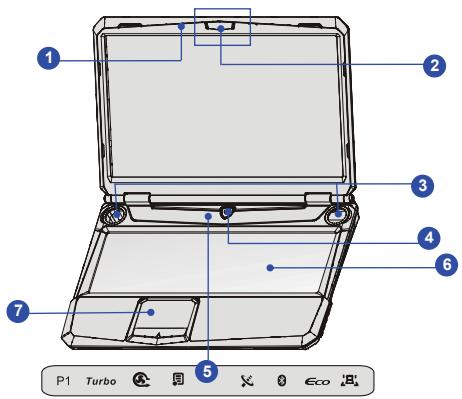
- Internal Microphone
- WebCam / Webcam LED
- Stereo Speakers
- Power Button / Power LED
- Quick Launch Touch Sensors
- Keyboard
- Touchpad
1. Internal Microphone
The built-in speaker and array microphone increase the accuracy of speech recognition feature, allow inputs to be combined into a single, higher-quality source.
2. Webcam/ Webcam LED (optional)
This built-in Webcam can be used for picture taking, video recoding or conferencing, and any other interactive applications.
- Webcam LED indicator, next to the webcam, glows amber when webcam function is activated; LED goes out when this function is turned off.
3. Stereo Speakers
Give high quality sound blaster with stereo system and Hi-Fi function supported.
4. Power Button / Power LED

- Press the power button to turn the notebook power ON and OFF.
♦ Glowing white when the notebook power is turned on.
5. Quick Launch Touch Sensors
Press the quick launch touch sensor to activate the specific applications or tools. With the help of these sensors, users will be able to do work more efficiently.
P1
User Defined or Windows Search (optional)
- Press this sensor to launch the User Defined application.
- Or, press this sensor to launch the Windows Search function.
Turbo
- Connect the AC power and press the TURBO sensor to raise a higher performance. The TURBO LED indicators lights when this function is ON or goes out when OFF.
Note
- This notebook is designed to support overclocking function.
However, please make sure your components are able to tolerate such abnormal setting while doing overclocking. Any attempt to operate beyond CPU and system specifications may cause damages. We do not guarantee the damages or risks caused by inadequate operation or beyond product specifications. - The overclocking value may vary depending on the CPU you use.
- Factory warranty will be void if the original equipped CPU or DRAM is replaced.

Cooler Boost
- Press this sensor to activate fan to run at full speed to cool down overall temperature.
- Press this sensor repeatedly to turn the Cooler Boost function on or off recurrently.

Windows Start Up Hotkey
- Press this sensor to avoid mispressing Windows Start Up Hotkey and disturbing ongoing game.
- Press this sensor repeatedly to turn the Windows Start Up Hotkey function on or off recurrently.

- Press this sensor repeatedly to turn the WLAN function on or off recurrently.

- Press this sensor repeatedly to turn the Bluetooth function on or off recurrently.
ECO
ECO Engine (Power Saving)
- Press this sensor repeatedly to switch among these five different power saving modes – Gaming mode, Movie mode, Presentation mode, Office mode, and Turbo Battery mode provided by ECO Engine, or to turn this function off recurrently.
- Refer to the Power Management section in chapter 3 of this manual for the detailed information of this ECO Engine, Power Saving Function.

LED Mode Switch
- Press this sensor repeatedly to turn on or off all decorate LED around panel and lower cover.
6. Keyboard
The built-in keyboard provides all the functions of a standard keyboard.
Quick Launch [Fn] Buttons
Use the [Fn] buttons on the keyboard to activate the specific applications or tools.
With the help of these quick launch buttons, users will be able to work more efficiently.
![MSI GT663R - Quick Launch [Fn] Buttons - 1](/content/2025/01/138355/images/c97997dd398c3e17ec19daf21fb59a1434032ce0adbd2b5ef0e4049a35c22be4.jpg)
User Defined/Windows Search (optional)
- Press and hold the Fn button, and then press the F4 button to launch the User Defined function.
- Or, press and hold the Fn button, and then press the F4 button to launch the Windows Search function.
![MSI GT663R - Quick Launch [Fn] Buttons - 2](/content/2025/01/138355/images/efd5e80e2afe726bfe984945b8593bf7696eed17cdffc708d895548b234e6678.jpg)
ECO Engine
(Power Saving)
- Press and hold the Fn button, and then press the F5 button repeatedly to switch among various power saving modes provided by ECO Engine, or to turn this function off recurrently.
- Refer to the Power Management section in chapter 3 of this manual for the detailed information of this ECO Engine, Power Saving Function.
![MSI GT663R - Quick Launch [Fn] Buttons - 3](/content/2025/01/138355/images/50c5fae08803141866db183af0e707ad8acdd17ec3f19829d6a6a5c6bc6ef19d.jpg)
Webcam
- Press and hold the Fn button, and then press the F6 button to turn the Webcam function on. Press again to turn it off.
![MSI GT663R - Quick Launch [Fn] Buttons - 4](/content/2025/01/138355/images/76e6cf6f4f30229ff82c43d9a0ef1a1e0ad0fb4ad64c3b36b9ce768cb78e4b66.jpg)
WLAN (WiFi)
- Press and hold the Fn button, and then press the F8 button repeatedly to turn the Wireless LAN (WiFi) function on or off recurrently.
![MSI GT663R - Quick Launch [Fn] Buttons - 5](/content/2025/01/138355/images/1dec1485d6ed6b201a5281ecddd467b3cec224a69cefe789d19179e82306a3a9.jpg)
Bluetooth
(optional)
- Press and hold the Fn button, and then press the F9 button to turn the Bluetooth function on. Press again to turn it off.
![MSI GT663R - Quick Launch [Fn] Buttons - 6](/content/2025/01/138355/images/b9377c303b9e3624563f3560ecfc6c3865fbec3994a5a477959249e84b7819dd.jpg)
3G
(optional)
- Press and hold the Fn button, and then press the F10 button to turn the 3G function on. Press again to turn it off. - This 3G function is optional supported depending on the model users purchased. This function button will not be available when the 3G function is not supported. - Note that the function is not supported by this model.
7. Touchpad
This is a pointing device of the notebook.
Front View
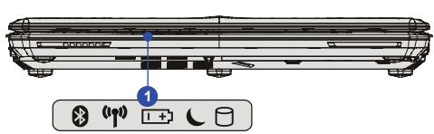
- Status LED
1. Status LED

Bluetooth

Wireless LAN
Bluetooth and Wireless LAN:
- Wireless LAN LED indicator glows amber when Wireless LAN function is enabled.
- Bluetooth LED indicator glows amber when Bluetooth function is enabled.
- Both LED indicators go out when both functions are disabled.
- Warning: For flight safety consideration, make sure these two LED indicators go out when you are in flight.
Note: The Bluetooth function may be optional supported depending on the model users purchased.
 | Battery Status:♦ Glowing amber when the battery is being charged.♦ Glowing blue when the battery is in low battery status.♦ Blinking blue if the battery fails and it is recommended to replace a new battery. Consult the local dealer for purchasing an equivalent type of battery recommended by the manufacturer.♦ Battery LED goes out when it is fully charged or when the AC/DC adapter is disconnected. |
| (###) | Sleep State:♦ Blinking amber when the system is in Sleep state.♦ LED goes out when the system is turned off. |
| [X6DA] | Hard Disk/ Optical Drive Device In-use:Blinking amber when the system is accessing the hard disk drive or the optical drive device. |
Right Side View
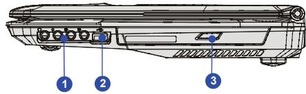
- Audio Port Connectors
- USB Port
- Optical Drive Device
1. Audio Port Connectors
Make high quality sound blaster with stereo system and Hi-Fi function supported. Connect your speakers to the proper connectors as shown below.
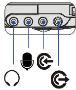
natural_image
Diagram of a device with labeled ports and icons (no text or symbols)
Headphone out/ SPDIF-out: Used for speakers or headphones. The S/PDIF connector is also provided for digital audio transmission to external speakers through an optical fiber cable. Connect the Front speakers here.

Mic In: Used for an external microphone. Connect the Center and Subwoofer speakers here.

Connect the Rear speakers here.

Line Out: A connector for speakers.
Connect the Surround speakers here.
2. USB Port
The USB port allows you to connect USB-interface peripheral devices, such as the mouse, keyboard, modem, portable hard disk module, printer and more.
3. Optical Drive Device
The optical drive device allows you to use the CD/ DVD/ Blu-ray disc for installing software, accessing data and playing music/movie on the computer.
Left Side View
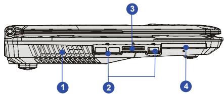
- Ventilator
- USB Port
- Card Reader
- ExpressCard Slot
1. Ventilator
The ventilator is designed to cool the system. DO NOT block the ventilator for air circulation.
2. USB Port
The USB port allows you to connect USB-interface peripheral devices, such as the mouse, keyboard, modem, portable hard disk module, printer and more.
3. Card Reader
The built-in card reader may support various types of memory card, such as MMC (Multi-Media Card), XD (eXtreme Digital), SD (Secure Digital), SDHC (SD High Capacity), MS (Memory Stick) or MS Pro (Memory Stick Pro) cards. Contact the local dealer for further and correct information and be noted that the supported memory cards may vary without notice.
4. ExpressCard Slot
The notebook provides an ExpressCard slot. The new ExpressCard interface is smaller and faster than PC Card interface. The ExpressCard technology takes advantage of the scalable, high-bandwidth serial PCI Express and USB interfaces.
Rear Side View
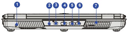
- Kensington Lock
- Power Connector
- RJ-45 Connector
- VGA Port
- E-SATA Connector
- HDMI Connector
- Ventilator
1. Kensington Lock
This notebook provides a Kensington Lock hole, which allows users to secure the notebook in place with a key or some mechanical PIN device and attached through a rubberised metal cable. The end of the cable has a small loop which allows the whole cable to be looped around a permanent object, such as a heavy table or other similar equipment, thus securing the notebook in place.
2. Power Connector
To connect the AC/ DC adapter and supply power to the notebook.
3. RJ-45 Connector
The Ethernet connector is used to connect a LAN cable for network connection.
4. VGA Port
The 15-pin D-sub VGA port allows you to connect an external monitor or other standard VGA-compatible device (such as a projector) for a great view of the computer display.
5. E-SATA Connector
The E-SATA Connector allows you to connect an external Serial ATA device. Users can now utilize shielded cable outside the notebook to take advantage of the benefits the SATA interface brings to storage.
6. HDMI Connector
HDMI (High Definition Multimedia Interface) is a new interface standard for PCs, displays and consumer electronics devices that supports standard, enhanced and high-definition video, plus multi-channel digital audio on a single cable.
7. Ventilator
The ventilator is designed to cool the system. DO NOT block the ventilator for air circulation.
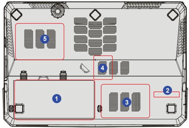
Bottom Side View
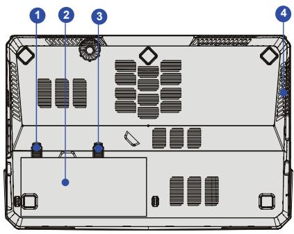
- Battery Lock/ Unlock Button
- Battery Pack
- Battery Release Button
- Ventilator
1. Battery Lock/ Unlock Button
Battery cannot be moved when the button is positioned on lock status. Once the button is slid to unlock position, the battery is removable.
2. Battery Pack
This notebook will be powered by the battery pack when the AC/ DC adapter is disconnected.
3. Battery Release Button
It is a bounce-back device as a preparation for releasing the battery pack. Slide it with one hand and pull the battery pack carefully with the other.
4. Ventilator
The ventilator is designed to cool the system. DO NOT block the ventilator for air circulation.
CHAPTER 3
Getting Started
Exclusive Functions
This model has following exclusive functions.
NVIDIA OC Tool
This tool can activate TDE (Turbo Drive Engine) technology, thus further enable CPU and GPU OC function.
Note:
- The nVidia Over Clock Tool is only available on graphic solution only.
- The preinstalled MXM card may differ depending on the model user purchased.
This notebook is designed to support overclocking function. However, please make sure your components are able to tolerate such abnormal setting while doing overclocking. Any attempt to operate beyond CPU and system specifications may cause damages. We do not guarantee the damages or risks caused by inadequate operation or beyond product specifications. -
The overclocking value may vary depending on the CPU you use.
Factory warranty will be void if the original equipped CPU or DRAM is replaced. -
To use the TDE – over-clocking function, follow the instructions below:
Turbo
Connect the AC power and press the TURBO sensor to raise a higher performance. The TURBO LED indicators lights when this function is ON or goes out when OFF.
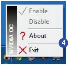
- Right-click the NVIDIA OC icon once on tool bar.
- Select "Enable" or "Disable" to activate GPU Over Clock Function.
2

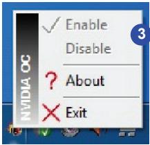

With this TDE function activated, the system will raise the over-clocking setting to achieve a higher performance, and the icon on behalf of TDE function enabled will appear on the display.

The icon on behalf of TDE function disabled will appear on the display when this function is turn off.
- Select "About" to know the version of NVIDIA OC tool, or click "Exit" to leave the application.
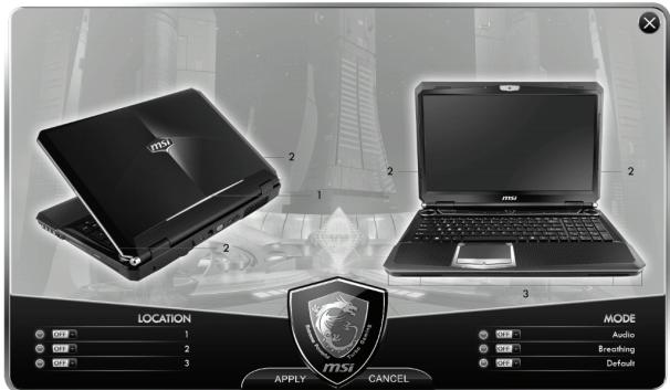
SLM Setting (System LED Manager)
SLM tool can adjust the LED behavior around panels and base side. Users can decide which side of LED light to be visible, whereas others invisible, yet to choose the lighting effects mode.
- User may call tool up to desktop either by left-clicking twice or right-clicking once and select "Setting" option.
1


Setting
Exit
2. SLM screen shows as follows.
Audio Mode LED lights along with music or any sound from notebook.
Breathing
Mode
LED lights as frequency of human breathing.
Default Mode LED lights following factory settings.
2
Power Management
Connecting the AC power
Please be noted that it is strongly recommended to connect the AC/DC adapter and use the AC power while using this notebook for the first time. When the AC/DC adapter is connected, the battery is being charged immediately.
Note that the AC/DC adapter included in the package is approved for your notebook; using other adapter model may damage either the notebook or other devices attached to it.
Do not cover the AC/DC adapter since it may produce a certain heat while in use. Always be aware of heat coming from the AC/DC adapter in use.
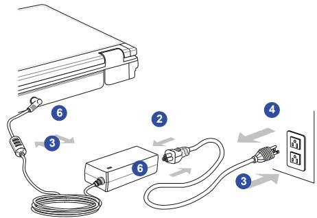
Connecting the AC Power
- Unpack the package to find the AC/DC adapter and power cord.
- Attach the power cord to the connector of the AC/DC adapter.
- Plug the DC end of the adapter to the notebook, and the male end of the power cord to the electrical outlet.
Disconnecting the AC Power
When you disconnect the AC/DC adapter, you should:
- Unplug the power cord from the electrical outlet first.
- Unplug the connector from the notebook.
- Disconnect the power cord and the connector of AC/DC adapter.
- When unplugging the power cord, always hold the connector part of the cord. Never pull the cord directly!
Using the Battery Power
This notebook is equipped with a high-capacity Li-ion battery pack. The rechargeable Li-ion battery pack is an internal power source of the notebook.
Be aware of that this battery pack may be damaged if users try to disassemble the battery pack on their own. Also, note that the limited warranty to the battery pack may also lose its efficacy when this battery pack is disassembled not by an authorized machinist.
To prevent explosion caused by improper battery replacement, use the same or equivalent type of battery recommended by the manufacturer only.
Always keep the battery which is not in use in a safe place.
Please follow your local laws and regulations to recycle the unused battery pack.
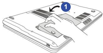
Installing the Battery Pack
To insert the battery pack, following the steps below:
- Align and place the battery to the battery tray with correct orientation.
- Press down the battery pack to fasten the battery pack in the battery tray.
- Press the lock/unlock button to the Lock position to make sure the battery pack is securely fastened.
natural_image
Illustration of a hand inserting a component into a device (no text or symbols visible)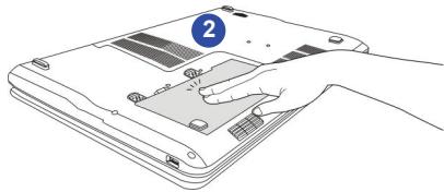
natural_image
Line drawing of a hand inserting a component into a laptop keyboard (no text or symbols)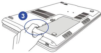
natural_image
Diagram of a laptop keyboard with a hand inserting a button (no text or symbols present)Releasing the Battery Pack
It is always recommended to have another battery pack in reserve for enough power supply. Please contact your local dealer to purchase a battery pack that is compliant to your notebook.
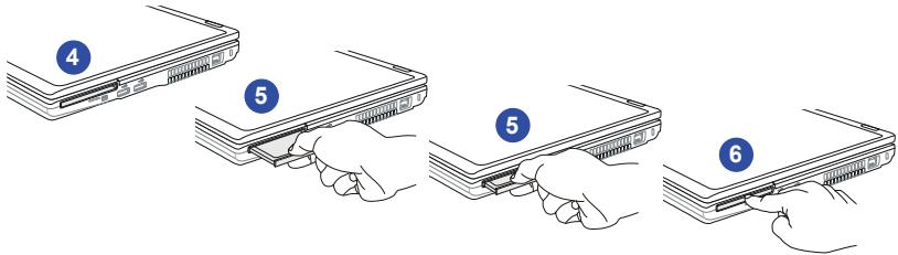
To remove the battery pack, following the steps below:
- Make sure the notebook is turned off, and the AC power is disconnected.
- Press the lock/unlock button to the unlocked position.
- Locate the battery release button on the bottom side.
- Push and hold the release button to the battery releasing direction as shown on the bottom side.
- Dig the edge of battery pack out of the battery tray with your finger tip. Be careful with your finger while trying to take out the battery pack.
- And then pull the battery pack out.
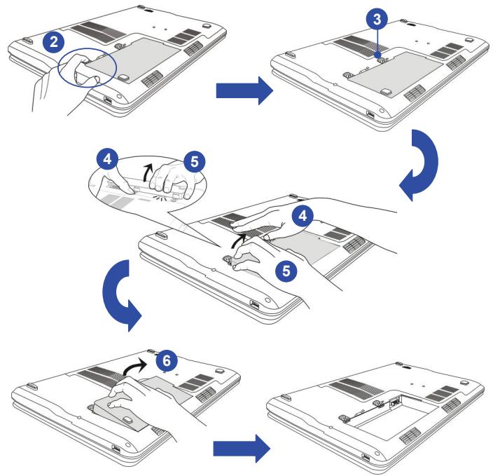
flowchart
graph TD
    A["Step 2: Hand press on laptop"] --> B["Step 3: Cover or switch"]
    B --> C["Step 4: Touch or press with hand"]
    C --> D["Step 5: Wrap or press with hand"]
    D --> E["Step 6: Close or fold change"]
    E --> F["Step 7: Cut or press with hand"]
Battery Safety Tips
Replacing or handling the battery incorrectly may present a risk of fire or explosion, which could cause serious injury.
- Only replace the main battery pack with the same or equivalent type of battery.
Do not disassemble, short-circuit or incinerate batteries or store them to temperatures above +60°C (+140°F). - Do not temper with batteries. Keep away from the reach of children.
- Do not use rusty or damaged batteries.
- Dispose of batteries according to local regulations. Check with your local solid waste officials for details about recycling options or for proper disposal in your area.
Conserving Battery Power
Efficient battery power is critical to maintain a normal operation. If the battery power is not managed well, the saved data and customized settings may be lost.
To optimize battery life and avoid a sudden power loss, read the tips below:
- Suspend system operation if the system will be idle for a while or shorten the suspend timer's time period.
- Turn off the system if you won't be using it for a period of time.
- Disable unnecessary settings or remove idle peripherals.
- Connect an AC/DC adapter to the system whenever possible.
Charging the Battery Pack
The battery pack can be recharged while it is installed in the notebook. Please pay attention to the following tips before recharging the battery:
If a charged battery pack is not available, save your work and close all running programs and shut down the system or Save-to-Disk.
♦ Plug in an external AC/DC adapter.
- You can use the system, suspend system operation or shut down and turn off the system without interrupting the charging process.
The battery pack uses Lithium-ion battery cells that have no “memory effect.” It is unnecessary to discharge the battery before recharging. However, to optimize the life of battery, we suggest that consuming the battery power completely once a month is necessary.
If you do not use the notebook for a long time, it is suggested to remove the battery pack from your notebook. This may be helpful to extend your battery life.
- The actual charging time will be determined by the applications in use.
ECO Power Saving Function (Optionally Supported)
Enabling the ECO Engine
ECO Engine, the outstanding and unique power saving function, provides various power saving modes – Gaming mode, Movie mode, Presentation mode, Office mode, and Turbo Battery mode, to extend the battery running time while performing different tasks with this notebook.
Read the instructions bellow to activate the ECO Engine power saving function:
- Press and hold the Fn button.
- Press the F5 button repeatedly to switch among the different modes of ECO Engine, or to turn this ECO Engine off recurrently.
- To learn which power saving mode is activated presently, read the icon on behalf of each mode appearing on the display when selected.

Gaming Mode
Gaming Mode
Select this mode while performing game applications.

Movie Mode
Movie Mode
Select this mode while playing multimedia applications

Presentation Mode
Presentation Mode
Select this mode while performing presentation applications.

Office Mode
Office Mode
Select this mode while dealing with office documentation tasks.

Turbo Battery Mode
Turbo Battery Mode
Select this mode to maximize the battery running time.

ECO Off
Selected to disable ECO Engine.
Power Management in Windows OS
Power management of personal computers (PCs) and monitors has the potential to save significant amounts of electricity as well as deliver environmental benefits. To be energy efficient, turn off your display or set your PC to sleep or hibernate mode after a period of user inactivity.
Follow the instructions below to adjust the power management settings in Windows OS:
- "Power Options" selection in Windows OS allows you to control the power management features of your display, hard drive, and battery. Go to the Start menu and click on the Control Panel. Click on the "System and Security".
- Then click on the "Power Options".
- Then "Select a power plan" that meets your personal needs.
- The "Shut down" Computer menu will present various relative options as following.
-
The computer should be able to wake up from power saving mode in response to a command from any of following:
-
the power button,
the mouse,
the keyboard.
1

System and Security
Review your computer's status
Back up your computer
Find and fix problems
2

Power Options
Require a password when the computer wakes
Change what the power buttons do
Change when the computer sleeps
Select a power plan
Power plans can help you maximize your computer's performance or conserve energy. Make a plan active by selecting it, or choose a plan and customize it by changing its power settings. Tell me more about power plans
Preferred plans

Balanced (recommended)
Change plan settings
Automatically balances performance with energy consumption on capable hardware.

Power saver
Change plan settings
Saves energy by reducing your computer's performance where possible.
Show additional plans

4
Shut down

Switch User
Log Off
Lock
Restart
Sleep
Hibernate
Energy Saving Tips
- Activate the ECO power saving function to manage the computer’s energy consumption.
- Turn off the monitor after a period of user inactivity.
Utilize the Fn and F12 sleep mode keys to turn into power saving mode. - Tune the settings in Power Options under Windows OS to optimize the computer's power management.
- Always disconnect the AC power cord or uninstall the battery pack or switch off the wall socket if the computer would be left unused for a certain time to achieve zero energy consumption.
Basic Operations
If you are a beginner to the notebook, please read the following instructions to assure your own safety, and make yourself comfortable during the operations.
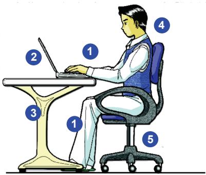
Safety and Comfort Tips
The notebook is a portable platform that allows you to work anywhere. However, choosing a good workspace is important if you have to work with your notebook for a long period of time.
- Your work area should have enough illumination.
- Choose the proper desk and chair and adjust their height to fit your posture when operating.
- When sitting on the chair, adjust the chair's back (if available) to support your back comfortably.
Place you feet flat and naturally on the floor, so that your knees and elbows have the proper position (about 90-degree) when operating. - Put your hands on the desk naturally to support your wrists.
- Adjust the angle/position of the LCD panel to have an optimal view.
- Avoid using your notebook in the space where may cause you discomfort (such as on the bed).
-
The notebook is an electrical device, please treat it with great care to avoid personal injury
-
Keep your hands and feet with optimal comfort.
- Adjust the angle and position of LCD panel.
- Adjust the desk's height.
- Sit straight and keep a good posture.
- Adjust the chair's height.
Having a Good Work Habit
Have a good work habit is important if you have to work with your notebook for long periods of time; otherwise, it may cause discomfort or injury to you. Please keep the following tips in mind when operating.
- Change your posture frequently.
♦ Stretch and exercise your body regularly. - Remember to take a break after working for a period of time.
Knowing the Keyboard
This notebook provides a full-functioned keyboard. This keyboard can be divided into four categories: Typewriter keys, Cursor keys, Numeric keys and Function keys.
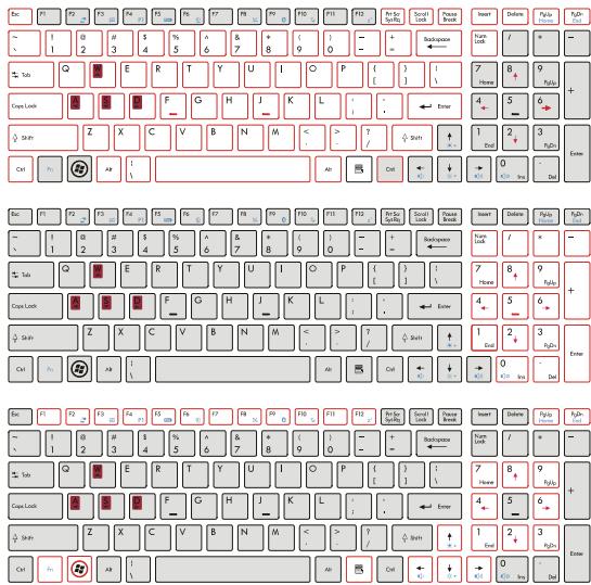
Typewriter keys
Numeric keys
Cursor keys /
Function keys
Typewriter Keys
In addition to providing the major function of the keyboard, these typewrite keys also provide several keys for special purposes, such as [Ctrl,] [Alt,] and [Esc] key.
When the lock keys are pressed, the corresponding LEDs will light up to indicate their status:
■ Num Lock: Press the Num Lock key to toggle the Num Lock on and off. When this function is activated, you can use the numeric keys that are embedded in the typewriter keys.
■ Caps Lock: Press the Caps Lock key to toggle the Caps Lock on and off. When this function is activated, the letters you type are kept in uppercase.
■ Scroll Lock: Press the Scroll Lock key to toggle the Scroll Lock on and off. This function is defined by individual programs, and is usually used under DOS.
Numeric Keys
Find the numeric keys among the keyboard, and activate the Num Lock function to use these numeric keys to enter numbers and calculations.
Cursor Keys
The four cursor (arrow) keys and [Home], [PgUp], [PgDn], [End] keys are used to control the cursor movement.

Move the cursor left for one space.

Move the cursor right for one space.

Move the cursor up for one line.

Move the cursor down for one line.

Move to the previous page.

Move to the next page.

Move to the beginning of the line (or document).


Move to the end of the line (or document).
The Backspace key, [Ins] and [Del] keys at upper right corner are use for editing purpose.

This key is used to switch the typing mode between “insert” and “overtype” modes.

Press this key to delete one character to the right of the cursor and move the following text left for one space.
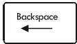
Press this key to delete one character to the left of the cursor and move the following text left for one space.
Function Keys
■ Windows Keys
You can find the Windows Logo key (☑) and one Application Logo key (☐) on the keyboard, which are used to perform Windows-specific functions, such as opening the Start menu and launching the shortcut menu. For more information of the two keys, please refer to your Windows manual or online help.
■ [Fn] Key
![MSI GT663R - ■ [Fn] Key - 1](/content/2025/01/138355/images/745fffc8e915c91a591cacb5073e8cd2661161fbe79fef1cfc6f6b8e0517c68a.jpg)
Switch the display output mode between the LCD, external monitor and both.
![MSI GT663R - ■ [Fn] Key - 2](/content/2025/01/138355/images/dfd7f6064ecdc401ec6b45c14410d40e533c8f40a58bb18493b5152d4ecd69ad.jpg)
Enable or disable the touchpad function.
![MSI GT663R - ■ [Fn] Key - 3](/content/2025/01/138355/images/6b19898029907a2fb09fcb856329ee732a7c29824612387c8c699322fcb244de.jpg)
Decrease the LCD brightness.
![MSI GT663R - ■ [Fn] Key - 4](/content/2025/01/138355/images/2b4dc622076914e37bacd4f82053f8b3e86b217aea4b634ba07dc1245697d80b.jpg)
Increase the LCD brightness.
![MSI GT663R - ■ [Fn] Key - 5](/content/2025/01/138355/images/9775a98dcd500143d168b99aaee618ebb460622a069c1559a19270fbf9ec3958.jpg)
Decrease the built-in speaker's volume.
![MSI GT663R - ■ [Fn] Key - 6](/content/2025/01/138355/images/8c3839f98cccbf006b85446adac5a17b66b8924e3f44abb3e1d7215cc846264b.jpg)
Increase the built-in speaker's volume.
![MSI GT663R - ■ [Fn] Key - 7](/content/2025/01/138355/images/a000aa7637d96a3e5ee89eee920b7d7493ae154d2a681535c46af02fe126dfe6.jpg)
Disable the computer's audio function.
![MSI GT663R - ■ [Fn] Key - 8](/content/2025/01/138355/images/2b5ca02ac3f6e334579a39bf9dc00605f7d1f8c1292dd8ab88d67c631c8f1cd9.jpg)
Force the computer into sleep state (depending on the system configuration).
■ Quick Launch [Fn] Buttons
Use the [Fn] buttons on the keyboard to activate the specific applications or tools.
With the help of these quick launch buttons, users will be able to do work more efficiently.
![MSI GT663R - ■ Quick Launch [Fn] Buttons - 1](/content/2025/01/138355/images/ee8f5f35ec3d263b814ea012f4f03b25c34acc43f73d2df6b0f292778d67183e.jpg)
User Defined or Windows Search (optional)
- Press and hold the Fn button, and then press the F4 button to launch the User Defined function.
Or, press and hold the Fn button, and then press the F4 button to launch the Windows Search function.
![MSI GT663R - ■ Quick Launch [Fn] Buttons - 2](/content/2025/01/138355/images/fba2bedfbdc4ff21bbae15f20351e25d2674bcea8ec4af7211733c263d6ac2e6.jpg)
ECO Engine (Power Saving)
- Press and hold the Fn button, and then press the F5 button repeatedly to switch among various power saving modes provided by ECO Engine, or to turn this function off recurrently.
- Refer to the Power Management section in chapter 3 of this manual for the detailed information of this ECO Engine, Power Saving Function.
![MSI GT663R - ■ Quick Launch [Fn] Buttons - 3](/content/2025/01/138355/images/f8ede422adfce61c54830d6611ff3421d04b5802cd633d7ea6c5743cfadbeece.jpg)
Webcam
- Press and hold the Fn button, and then press the F6 button to turn the Webcam function on. Press again to turn it off.
![MSI GT663R - ■ Quick Launch [Fn] Buttons - 4](/content/2025/01/138355/images/03304c9b18b1c3c29e014ed10644c1cca9d2204ec91c2ad5c8ca5b744d7a315a.jpg)
WLAN (WiFi)
- Press and hold the Fn button, and then press the F8 button repeatedly to turn the Wireless LAN (WiFi) function on or off recurrently.
![MSI GT663R - ■ Quick Launch [Fn] Buttons - 5](/content/2025/01/138355/images/8e6e80479d9aceb0042ba15aca195ac1f651b7252c6f9c3e8568ab6b282369d1.jpg)
Bluetooth (optional)
- Press and hold the Fn button, and then press the F9 button to turn the Bluetooth function on. Press again to turn it off.
![MSI GT663R - ■ Quick Launch [Fn] Buttons - 6](/content/2025/01/138355/images/fe8029c719d12ccbcaee3aba6260a251932a642bb7244bdaeed5b760cce02f73.jpg)
3G
(optional)
- Press and hold the Fn button, and then press the F10 button to turn the 3G function on. Press again to turn it off. - This 3G function is optional supported depending on the model users purchased. This function button will not be available when the 3G function is not supported.
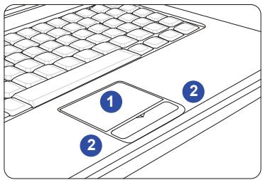
Knowing the Touchpad
The touchpad integrated in your notebook is a pointing device that is compatible with standard mouse, allowing you to control the notebook by pointing the location of the cursor on the screen and making selection with its two buttons.
1. Cursor Movement Area
This pressure-sensitive area of the touchpad, allows you to place your finger on and control the cursor on the screen by moving one of your finger.
2. Right / Left Buttons
Acts as the mouse's right/ left button.
Using the Touchpad
Read the following description to learn how to use the touchpad:
■ Configuring the Touchpad
You can customize the pointing device to meet your personal needs. For example, if you are a left-handed user, you may want to swap the functions of the two buttons. In addition, you can change the size, shape, moving speed and other advanced features of the cursor on the screen. To configure the touchpad, you can use the standard Microsoft or IBM PS/2 driver in your Windows operating system. The Mouse Properties in Control Panel allows you to change the configuration.
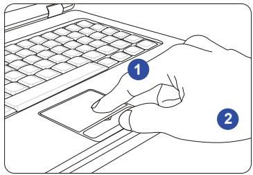
■ Positioning and Moving
Place your finger on the touchpad (usually using the forefinger), and the rectangular pad will act as a miniature duplicate of your display. When you move your fingertip across the pad, the cursor on the screen will move simultaneously to the same direction. When your finger reaches the edge of the pad, lift your finger and place it on a proper location of the touchpad to continue the movement.
■ Point and Click
When you have moved and placed the cursor over an icon, a menu item or a command that you want to execute, simply tap slightly on the touchpad or press the left button to select. This procedure, called as point and click is the basics of operating your notebook. Unlike the traditional pointing device such as the mouse, the whole touchpad can act as a left button, so
that your each tap on the touchpad is equivalent to pressing the left button. Tapping twice more rapidly on the touchpad is to execute a double-click.
■ Drag and Drop
You can move files or objects in your notebook by using drag-and-drop. To do so, place the cursor on the desired item and slightly tap twice on the touchpad, and then keep your fingertip in contact with the touchpad on the second tap. Now, you can drag the selected item to the desired location by moving your finger on the touchpad, and then lift your finger from the touchpad to drop the item into place. Alternately, you can press and hold the left button when you select an item, and then move your finger to the desired location; finally, release the left button to finish the drag-and-drop operation.
- Move the cursor by sliding your fingertip.
- Put your wrist on the desk comfortably.
About Hard Disk Drive
Your notebook is equipped with a 2.5-inch hard disk drive. The hard disk drive is a storage device with much higher speed and larger capacity than other storage devices, such as the floppy disk drive and optical storage device. Therefore, it is usually used to install the operating system and software applications.
To avoid unexpected data loss in your system, please backup your critical files regularly.
Do not turn off the notebook when the hard disk In-use LED is on.
Do not remove or install the hard disk drive when the notebook is turned on. The replacement of hard disk drive should be done by an authorized retailer or service representative.
Using the Optical Storage Device
Your notebook is equipped with an optical storage device. The actual device preinstalled in your notebook depends on the model you purchased.
■ DVD Super Multi: This device allows you to read DVD and CD, and record CD format.
■ Blu-ray: It is a high-capacity optical disc that holds 4.5 hours of high-definition video (HD) on a single-sided, single-layer 25GB disk. Blu-ray supports the more advanced H.264 and VC-1 video encoding algorithms (codecs) as well as MPEG-2, which is used for DVD. It also supports 1080p, the highest HDTV resolution.
- Confirm that the disk is placed correctly and securely in the tray before closing the tray.
- Do not leave the disk tray open.
Inserting the Disk
The following instructions describe the general procedure when operating the optical storage device:
- Confirm that the notebook is turned on.
- Press the eject button on the panel and the disk tray will slide out partially.
-
Gently pull the tray out until fully extended.
-
Place your disk in the tray with its label facing up. Slightly press the center of the disk to secure it into place.
-
Push the tray back into the drive.
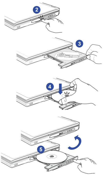
Removing the Disk
Follow the instructions below to remove the disk that is placed in the optical storage device:
- Press the eject button on the drive's panel and the disk tray will slide out partially.
- Gently pull the tray out until fully extended.
- Hold the disk by its edge with your fingers and lift it up from the tray.
- Push the tray back into the drive.
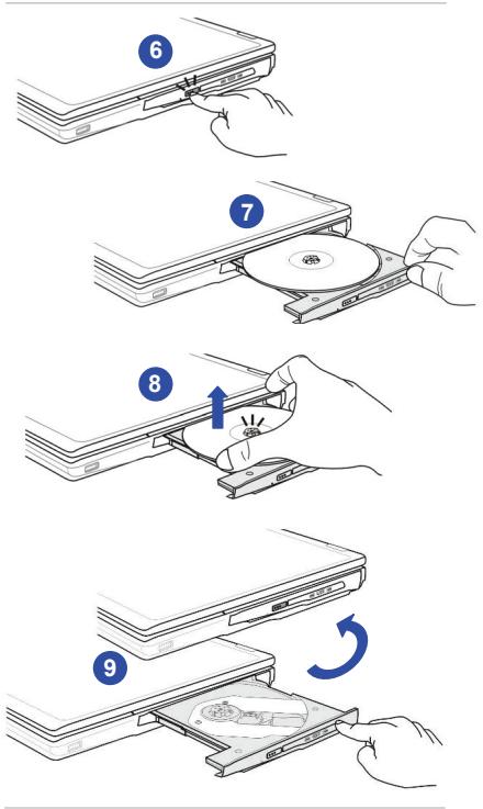
Connecting the External Devices
The I/O (input/output) ports on the notebook allow you to connect peripheral devices. All devices listed here are for reference only.
Connecting the Peripheral Devices
Connecting the USB devices
This notebook provides USB ports for connecting various USB devices, such as mouse, keyboard, digital camera, webcam, printer, and external optical storage device, etc. To connect these devices, install the drivers for each device first if necessary, and then connect the device to the notebook.
This notebook is capable to auto detect the USB devices installed, and if there is no detection of the devices, please manually enable the USB devices by going to Start Menu / Control Panel / Add
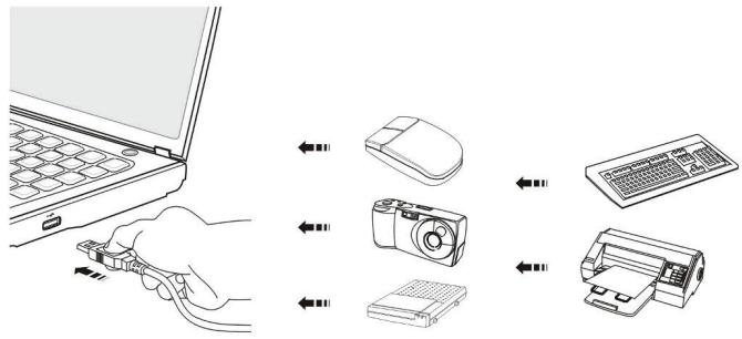
Connecting the External Display Devices
This notebook provides a VGA port for connecting a larger display with higher resolution. The 15-pin D-sub VGA port allows users to connect an external monitor or other standard VGA-compatible device (such as a projector) for a great view of the notebook display.
This notebook provides a HDMI port for connecting a larger display with higher resolution. HDMI (High Definition Multimedia Interface) is a new interface standard for PCs, displays and consumer electronics devices that supports standard, enhanced and high-definition video, plus multi-channel digital audio on a single cable.
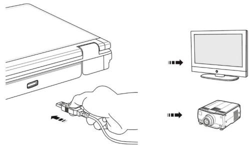
To connect the external display, make sure the notebook and the external display are both powered off, and then connect the display to the notebook.
Once the display is connected to the notebook, power on the notebook and the external display should respond by default. If not, you can switch the display mode by pressing [Fn]+[F2] . Alternately, you can change the display mode by configuring the settings in Display Properties of Windows operating system.
Connecting the External SATA Hard Disk device
The E-SATA Connector allows you to connect an external Serial ATA hard disk device. Users can now utilize shielded cable outside the notebook to take advantage of the benefits the SATA interface brings to storage.
The E-SATA standard interface supports “plug-and-play” technology, so that you can connect and remove the E-SATA devices without turning off the notebook.
To connect the E-SATA hard disk device, simply connect the cable of the device to the E-SATA Connector of your notebook.
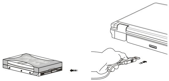
natural_image
Illustration showing a device with an attached folder and a hand inserting a cable to a connector (no text or symbols present)Connecting the Communication Devices
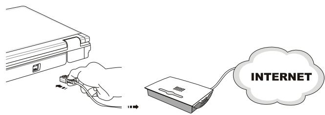
Using the LAN
The RJ-45 connector of the notebook allows you to connect the LAN (local area network) devices, such as a hub, switch and gateway, to build a network connection.
For more instructions or detailed steps on connecting to the LAN, please ask your MIS staff or network manager for help.
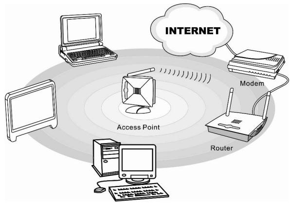
Using Wireless LAN Connection (optionally supported)
This notebook is equipped with wireless LAN module which allows users to perform fast data transmission with the standard IEEE 802.11 for wireless LAN. This gives users the mobility to move around within a broad coverage area and still be connected to the network.
By using the 64-bit/128-bit Wired Equivalent Privacy (WEP) encryption technology and Wi-Fi Protected Access feature, the optional built-in wireless LAN is capable to achieve a more efficient and a more secure solution to the wireless communication.
For more instructions or detailed steps on connecting to the Wireless LAN, please ask your MIS staff or network manager for help.
flowchart
graph TD
    A["Internet"] --> B["Modem"]
    B --> C["Router"]
    C --> D["Laptop"]
    D --> E["Access Point"]
    E --> A
    style A fill:#f9f,stroke:#333
    style B fill:#ccf,stroke:#333
    style C fill:#cfc,stroke:#333
    style D fill:#fcc,stroke:#333
    style E fill:#cff,stroke:#333
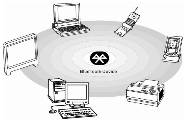
Using Bluetooth Connection (optionally supported)
This notebook is equipped with Bluetooth module which allows users to connect various Bluetooth-enabled devices to the notebook. Bluetooth provides a way to connect and exchange information between devices such as mobile phones, personal computers, printers, GPS receivers, PDAs, digital cameras, and video game consoles through a secure, globally unlicensed Industrial, Scientific and Medical (ISM) 2.4 GHz short-range radio frequency bandwidth.
For more instructions or detailed steps on using the Bluetooth function, please ask your MIS staff or network manager for help.
ExpressCard Installation
This computer provides an ExpressCard slot. The new ExpressCard interface is smaller and faster than PC Card interface. The ExpressCard technology takes advantage of the scalable, high-bandwidth serial PCI Express and USB 2.0 interfaces.
The following instruction provides you with a basic installation for the ExpressCard, including how to install and remove it. For more information, please refer to the manual of your ExpressCard.
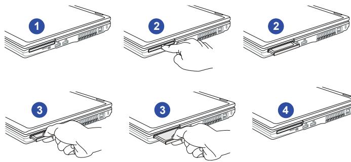
Removing the ExpressCard
- Locate the ExpressCard slot on your notebook. There might be a dummy card inserted in the slot, remove the ExpressCard or dummy card with the same steps below.
- Press the card to make the card stretch out first.
- Pull the card out of the slot
- Empty Slot
Installing the ExpressCard
- Insert the card into the slot (usually with its label facing up)
- Push the card into the slot until it is firmly seated.
Removing the ExpressCard
Installing the ExpressCard
Components Replacement and Upgrade
Please be noticed that the memory, hard disk drive, Wireless LAN/ Bluetooth module and battery pack preinstalled in the product users purchased may be upgradable or replaceable by user's request depending on the models users purchased.

natural_image
Illustration of a folder with documents and a blue circular badge (no text or symbols)This notebook is equipped with a high-capacity Li-ion battery pack, and the battery pack is replaceable by users.
To replace the battery pack, please refer to the section of Using the Battery Power for details.
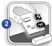
natural_image
Illustration of a hand holding a document with icons and a blue circle labeled '2' (no text or symbols on the document itself)This notebook is equipped with a wireless LAN / Bluetooth module, and the module may be upgradable and replaceable by authorized dealer or service center.
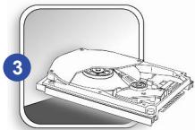
natural_image
Diagram of a hard disk drive with labeled component (no text or symbols present)This notebook is equipped with a hard disk drive, and this storage device may be upgradable and replaceable by the authorized dealer or service center.
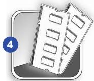
natural_image
Illustration of two computer RAM chips with slots, one partially filled and the other partially outlined (no text or symbols)Additional memory module may be installed, by the authorized dealer or service center, to increase the performance of this notebook, depending on the specification limitation.
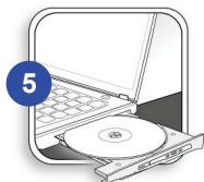
natural_image
Illustration of a laptop with an open CD and a CD inside, no text or symbols presentThis notebook is equipped with an optical drive device, and this storage device may be upgradable and replaceable by the authorized dealer or service center.
To learn more about upgrade limitation, please refer to the specification in the User's Manual provided. For any further information about the product users purchased, please contact the local dealer.
Do not attempt to upgrade or replace any component of the product, if you are not an authorized dealer or service center, since it may cause the warranty void. It is strongly recommended to contact the authorized dealer or service center for any upgrade or replace service.
CHAPTER 4
BIOS Setup
About BIOS Setup
When to Use BIOS Setup?
You may need to run the BIOS Setup when:
An error message appears on the screen during the system booting up and is requested to run SETUP.
- You want to change the default settings for customized features.
- You want to reload the default BIOS settings.
How to Run BIOS Setup?
To run the BIOS Setup Utility, turn on the notebook and press the [Del] key during the POST procedure.
If the message disappears before you respond and you still wish to enter Setup, either restart the system by turning it OFF and ON, or simultaneously pressing [Ctrl]+[Alt]+[Delete] keys to restart.
Be noted that the screen snaps and setting options in this chapter are for your references only. The actual setting screens and options on your Notebook may be different because of BIOS update.
Control Keys
You can use only the keyboard to control the cursor in the BIOS Setup Utility.

Press left arrow to select one menu title.

Press right arrow to select one menu title.

Press up arrow to select one item under the menu title.

Press down arrow to select one item under the menu title.

Increase the setting value or make changes.

Decrease the setting value or make changes.
1) Open the selected item to change setting options.
2) Bring up a sub-menu when available.
In some items, press this key to change setting field.

Bring up help screen providing the information of control keys.

1) Exit the BIOS Setup Utility.
2) Return to the previous screen in a sub-menu.
BIOS Setup Menu
Once you enter the BIOS Setup Utility, the Main Menu will appear on the screen. Select the tags to enter the other menus.
![Aptio Setup Utility - Copyright (C) 2009 American Megatrends, Inc. Main Advanced Boot Security Save & Exit Marketing Name Model Name System Date System Time [ : 11/20/2009] [10:14:11] ▶ SATA Information ▶ System Information Set the Date. Use Tab to switch between Date elements. ↔ Select Screen ¶ Select Item Enter: Select +/- Change Opt. F1: General Help P9: Optimized Defaults P10: Save ESC. Exit Version 2.00.1201 Copyright (C) 2009 American Megatrends, Inc.](/content/2025/01/138355/images/74c43d26e32725f4924a799a42b60d215a20ac7798cecd546924bb92e0d587f8.jpg)
Main Menu
Show system overview information about BIOS version, CPU features, memory size and setting of system time and date.
Advanced Menu
Adjust the advanced settings, such as RAID level 0, power consumption, USB/PCI devices, of the notebook in order to achieve a better performance.
Boot Menu
Set up boot type and boot sequence.
Security Menu
Install or clear the password settings for supervisor and user.
Save & Exit Menu
Save or discard the changes before leaving the BIOS Setup Menu.

The BIOS items and figures shown here are for reference only.
Main Menu
- System Date
This item allows you to set the system date. The date format is [day:month:date:year].
![Aptix Setup Utility - Copyright (C) 2008 American Megatrends, Inc. Main Advanced Boot Security Save & Exit Marketing Name Model Name System Date [11/20/2009] System Time [10:14:11] SATA Information System Information Set the Date. Use Tab to switch between Data elements. Select Screen M (Select Item Enter: Select P/- Change Opt. P1: General Help P3: Optimized Defaults P5: Save ESC: Ext Version 2.00.1231. Copyright (C) 2008 American Megatrends, Inc.](/content/2025/01/138355/images/e3eeb10000294286590c1429995a8fa7c4efed57fbd95dcbb8d650f5a1f4803a.jpg)
| Day | Day of the week, from Sun to Sat, which is determined by BIOS (read-only). |
| Month | The month from 01 (January) to 12 (December). |
| Date | The date from 01 to 31. |
| Year | The year can be adjusted by users. |
- System Time
This item allows you to set the system time. The system clock will go on no matter you shut down the PC or get into sleep mode. The time format is [hour:minute:second].
♦ SATA Information
These items display the types of the SATA devices installed in the notebook. Press [Enter] to bring up a window showing the detailed information of the device, including the device name, vendor, LBA mode, PIO mode and more.
- System Information
This item provides the information about the firmware, processor, and system memory.
Advanced Menu
Intel(R) SpeedStep(tm)
This item allows you to enable or disable Intel SpeedStep technology. When set to Disabled, the system always operates in a conserve power mode. If you want optimize the processor, set this item to Enabled, so that the processor's speed will be controlled by the use of your operating system and applications. Setting options: Enabled, and Disabled.
♦ SATA Mode Selection
Use this item to change the SATA Mode. Setting options: IDE, AHCI and RAID.
PCI Latency Timer
This item controls how long each PCI device can hold the bus before another takes over. When set to higher values, every PCI device can conduct transactions for a longer time and thus improve the effective PCI bandwidth.
For better PCI performance, you should set the item to higher values. Setting options: 32, 64, 96, 128, 160, 192, 224, and 248.
![Apti Setup Utility - Copyright (C) 2009 American Megarends, Inc. Main Advanced Boot Security Save & Exit SATA Mode Selection [Enabled] (RAD) [32 PCI Bus Clocks] PCI Latency Timer USB Configuration Enable/Cryable Intel(R) Speed/Gray(1M) → Select Screen P: Select item Enter: Select +/- Change Out. F1: General Help F9: Optimized Defaults F10: Save ESC Exit Version 2.00.1201 Copyright (C) 2009 American Megarends, Inc.](/content/2025/01/138355/images/0a5b3c4a029626334212a3063629c606b49411fde4d9f92cbf891b66bd2889d5.jpg)
Version 2.00.1201. Copyright (C) 2009 American Megatrends, Inc.
USB Configuration
Select this item to enter the sub-menu:
-- Legacy USB Support
Selecting Enabled allows users to use USB devices, such as mouse, keyboard, or portable disk, in DOS system; or allows users to boot the system by USB device. Setting options: Enabled, Disabled and Auto.
Boot Menu
- Set Boot Priority
Configure settings during system boot.
- Boot Option #1, #2, #3
These items allow you to set the sequence of boot devices where BIOS attempts to load the disk operating system.
![Aptio Setup Utility - Copyright (C) 2009 American Megamands, Inc. Main Advanced Boot Security Save & Exit Set Boot Priority (OD/ODV: T&58/Sup:OD/ODV,T&58/3) Boot Option #2 (SATA: WDC W0160/BEVT-753CT2) Boot Option #3 [NETWORK: Realtek Boot Agents] Set the system boot order. -> Select Screen M: Select Enter: Select +/- Change Opt. F1: General Help F9: Optimized Defaults F10: Save ESC Exit Version 2.00.1201 Copyright (C) 2009 American Megamands, Inc.](/content/2025/01/138355/images/975c9eeb7ee54838e729bc7c10c4ad323772707b216df4e74ed8f7cc721830d1.jpg)
Security Menu
♦ Supervisor Password / User Password
When this item is selected, a message box shall appear on the screen as below:
Enter New Password
Type a maximum of eight-digit password and press [Enter]. The password typed now will replace any previously set password from CMOS memory. You may also press [ESC] to abandon new password setting.
When the Supervisor Password is set, new items User Password and Password Check will be added in the menu.
Select User Password to give or to abandon password.
Note that Supervisor Password field allows users to enter and change the settings of the BIOS SETUP UTILITY, while User Password field only allows users to enter the BIOS SETUP UTILITY without having the authorization to make any change.
The Password Check item is used to specify the type of BIOS password protection that is implemented. Settings are described below:
| Setup | The password is required only when users try to access to BIOS SETUP UTILITY. |
| Always | The password is required every time when the Notebook is powered on or when users try to access to BIOS SETUP UTILITY. |
To clear a set Supervisor Password/ User Password, just press [Enter] under Supervisor Password/ User Password field when you are prompted to enter the password. Please note that when Supervisor Password has been cleared, User Password will be cleared as well. A message box will pop up confirming password will be disabled. Once the password is disabled, the system will boot and user can enter setup without entering password.
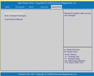
Save & Exit Menu
- Exit & Save Changes
Save the changes you have made and exit the utility. - Exit & Discard Changes
Exit the utility without saving the changes you have made.
Load Setup Defaults
Select this item to load the default settings.
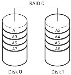
RAID Level 0 Introduction (Optionally Supported)
RAID level 0 is normally used to increase performance, which splits data evenly across two or more disks with no parity information for redundancy. This allows one of the drives to read data while the other drive is searching for and reading the next block.
NOTE: A RAID level 0 can be created with disks of different sizes, but the storage space added to the array by each disk is limited to the size of the smallest disk.
CAUTION: RAID level 0 provides no redundancy. Therefore, a failure of one drive results in the loss of all data. Regular backup helps data protection.
RAID0 Setup
This section helps user to set RAID level 0, generally used to increase performance, which splits data evenly across two or more disks with no parity information for redundancy.
![Aptio Setup Utility - Copyright (C) 2009 American Megatrends, Inc. Main Advanced Boot Security Save & Exit INTU/IC Speed/Depimer (Enable) PCI Latency Filter [32 PCI Data Clocks] USB Configuration ICE 414 Determines how SATA Container(s) operate [40V/Block Direction] << Select Screen ++ Select Item Enter: Select +/- Change Opt F1: General Help F9: Optimized Defaults F10: Save ESG: Exit Version 2.00.1201. Copyright (C) 2009 American Megatrends, Inc. Aptio Setup Utility - Copyright (C) 2009 American Megatrends, Inc. Main Advanced Boot Security Save & Exit USB Setup Changes Reset the system after saving Edit & Standard Changes Load Setup Defaults << Select Screen ++ Select Item Enter: Select +/- Change Opt F1: General Help F9: Optimized Defaults F10: Save ESG: Exit Version 2.00.1201. Copyright (C) 2009 American Megatrends, Inc.](/content/2025/01/138355/images/db493132954b2e41dc1b557dce291b325af51cee97009809887c2ddb5519e1c7.jpg)
- Enter “SATA Mode Selection” field in Advance tab, items IDE, AHCI, and RAID will pop up. Select the “RAID” item in the pop up menu.
- Choose “Exit & Save Changes” field under Save & Exit Menu to exit BIOS setting.
Creating RAID Volume
To create RAID Volume, follow the steps below:
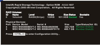
-
Reboot during POST, the following message will appear then press
to enter Configuration Utility. -
Enter Main Screen of Intel Rapid Storage Technology. Select "Create RAID Volume", and press ENTER.
1
2
![Intel(R)/ Rapid Storage Technology - Option ROM - 9.5.0.1037 Copyright© 2003-09 Intel Corporation, All Rights Reserved. [ MAIN MENU ] 1. Create R&D Volume 2. Delete R&D Volume 3. Reset Disks to Non-R&D 4. Recovery Volume Options 5. Exit [ DISK VOLUME INFORMATION ] R&D Volumes None Setailed. Physical Disks: Port Device Model Serial # 4 WDC WD6400BEY7-2 WD-WX0A08W5214 5 WDC WD6400BEY7-2 WD-WX1A08W10877 Size Type/StatusVol ID) 596.1GS Non-R&D Disk 596.1GS Non-R&D Disk (1) (2) - Select IESOP-Exit ENTERSSelect Menu](/content/2025/01/138355/images/167ba91bf2a89230cb7a566431af7d125f8489513bced5c046853c377cb71f9f.jpg)
- Create Volume Menu in the right appears, pressing ENTER to switch between various fields.
| Name | Specify an RAID Volume name. Default: Volume0 |
| RAID Level | RAID0(Stripe) |
| Disks | Not currently available |
| Stripe Size | Adjustable |
| Capacity | Adjustable |
| Sync | Not currently available |
3
![Intel(R) Rapid Storage Technology - Option ROM - 8.5.6.1037 Copyright(C) 2003-09 Intel Corporation. ABRights Reserved. CREATE VOLUME MENU Name: 10 KB RAD Event: RAD(S/Strps) Data: 10KB Units Strp Size: 12KB Capacity: 1152.3 GB Sync: N/A Create Volume HELP Enter a unique volume name that has no special characters and is 16-characters or less... [ ] Change [TAB]Next [ESC]Previous Menu [ENTER]Select](/content/2025/01/138355/images/29a89f79670f96b23618cf9c21ff3c7ec12adc31c27d8b34c473da2cfb51a3ca.jpg)
- Press enter when confirmed.
4
![Intel(R) Rapid Storage Technology - Option: ROM = 9.5.6.1037 Copyright(C): 2003-20 Intel Corporation. All Rights Reserved. CREATE VOLUME MENU Name: Volume RAD Level: RAD/Str(p) Data: 1647 Units Strip Size: 12KB Capacity: 1122.3GB Type: VBA [ ] [ HELP ] Press Enter to create the specified volume. [ ] [ Change] [ TARS-Next ] [ ESC-Previous Menu ] [ ENTER-Select ]](/content/2025/01/138355/images/014b414a97b6675664e8557d64d20b25a06b2fb9c8420e32c86e431bb261cf10.jpg)
- A Warning message prompted to confirm the RAID volume creation, press "Y" to continue.
5
![Intel(R) Rapid Storage Technology - Option ROM - 9.5.0.1037 Copyright©: 2003-30 Intel Corporation. All Rights Reserved. [ CAC#E # VOLUME MENU ] Name: Volume RAD Level: RAD(8/Strpe) Data: Data Tools Strip Size: 12KB Capacity: 1152.3GB Type: N/A WARNING: ALL DATA ON SELECTED DESK WILL BE LOST. Are you sure you want to create this volume? (YIN): Press Enter to create the specified volume. [ ] Change [TAB-Next] [ESC#Previous Menu] [ENTERSSelect]](/content/2025/01/138355/images/7809ff21c7de35254ca7b911ff9454ae32e7d0771ac8831a6802ec6f051c0f83.jpg)
- RAID information shows in the following screen indicating successful work.
6
![Intel(R) Rapid Storage Technology - Option ROM - 9.5.0-1037 Copyright(C) 2003-09 Intel Corporation. All Rights Reserved. MAIN MENU 1. Create R&D Volume 2. Create Disk Volume 3. Reset Disk to Non-R&D 4. Recovery Volume Options 5. Exit [ DISK/VOLUME INFORMATION ] R&D Volumes: ID Name Volume(s) Level R&D(S/Stripe) Stripe Size Status Available Yes PhysicalDisk: Port Device Model Serial # Size Type/Status/Val ID) WDC WD640BEV1-2 WD-WX0A8910214 5WD WD640BEV1-2 WD-WX10A8910877 5WD,1GB Member Disk(0) T1 12=Select [ESC]-Exit [ENTER]-Select Menu]](/content/2025/01/138355/images/55c5388cce6fad83dc848a0cc01d1a7f186539a2a1a03cd251d13b28e05bacff.jpg)
- Select ESC to exit and press Y to confirm.
Finally, restart the computer to finish RAID 0 setting.
7
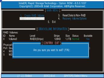
CAUTION: For users intended to use AHCI or RAID, set either item enabled in both BIOS PLUS Intel Rapid Storage Technology tool PRIOR to OS installation, or a screen showed error messages shall appear.
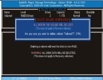
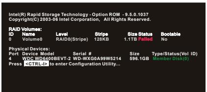
Deleting RAID Volume
To delete RAID Volume, follow the steps below:
- Select "Delete RAID Volume" field.
CAUTION: Once RAID volume is deleted, the data within shall be lost consequently, which means OS reinstallation is needed afterwards.
- Select volume user intends to remove, then press DEL.
1
![Intel(R): Rapid Storage Technology - Option ROM -9.5.0.1037 Copyright(C): 2003-29 Intel Corporation, AllRights Reserved. MAIN MENU 3. Reset Dials to Non-RAD. 4. Recovery Volume Options 5. Exit [ Disk/VOLUME INFORMATION ] RAID Volumes: ID Name Level Stripe Status Bootable Volume/0 RDID(Stripe) 12KB 1.1TB Normal Yes PhysicalData: Port Device Model Serial # Size Type(StatusVol ID) 4 WDC WD6400BEVT-2 WD-WXG0A8W5214 566,1GB Member Data(0) 5 WDC WD6400BEVT-2 WD-WX10A8W10877 566,1GB Member Data(0) F1 (-) = Select (ESC)-Exit (ENTER=Select Menu)](/content/2025/01/138355/images/7f7ec22d781c749c4641cb385e495c4a8b3dc590ed15b09d26d82b2ed03b5584.jpg)
2
![Intel(R): Rapid Storage Technology - Option ROM - 9.5.0.1037 Copyright© 2003-09 Intel Corporation: AIRrights Reserved. [ DEEER VOLUME: 100% ] Name Level Drives Capacity Status Bootable Volume SAVE(SNow) Normal Yes [ HELP ] Deleting a volume will reset the disks to non-RAD, WARNING: ALL DRK DATA WILL BE DELETED. (This does not apply to Recovery volumes) [1 ] - Select (ESC) Previous Menu (DEL) Delete Volume](/content/2025/01/138355/images/f96b26c7860cade2529865c0375789f1dceecd9872074fd2829071ed1965454a.jpg)
- A screen shows up to confirm RAID volume deletion, press "Y" to delete this volume.
3
Possible Error Scenario:
Following of two possible results might occur when you pressing CTRL+I, with only one HDD in your system.
NO FUNCTION; due to RAID volume has not been created yet. Intel Rapid Storage Technology tool will not be showed up.
- One of the hard disk removed after RAID volume had been created.

- Introductions
- Getting Started
- ExpressCard Installation.... 3-43
- Components Replacement and Upgrade 3-45
- BIOS Setup
- About BIOS Setup 4-2
- BIOS Setup Menu 4-4
- RAID Level 0 Introduction....4-13
- Regulations Information
- FCC-B Radio Frequency Interference Statement
- NOTE
- FCC Conditions
- CE Conformity
- Safety Instructions
- Green Product Features
- Environmental Policy
- 廢電池請回收
- Safety Guideline for Using Lithium Battery
- Trademarks
- CHAPTER 2
- Manual Map
- Unpacking
- Specification
- Product Overview
- Top-open View
- Internal Microphone
- Webcam/ Webcam LED (optional)
- Stereo Speakers
- Power Button / Power LED
- Quick Launch Touch Sensors
- P1
- Turbo
- Windows Start Up Hotkey
- ECO
- ECO Engine (Power Saving)
- LED Mode Switch
- Keyboard
- Quick Launch [Fn] Buttons
- Touchpad
- Front View
- Status LED
- Bluetooth and Wireless LAN:
- Right Side View
- Audio Port Connectors
- USB Port
- Optical Drive Device
- Left Side View
- Ventilator
- Card Reader
- ExpressCard Slot
- Rear Side View
- Kensington Lock
- Power Connector
- RJ-45 Connector
- VGA Port
- E-SATA Connector
- HDMI Connector
- Ventilator
- Bottom Side View
- Battery Lock/ Unlock Button
- Battery Pack
- Battery Release Button
- Ventilator
- CHAPTER 3
- Exclusive Functions
- NVIDIA OC Tool
- Note:
- SLM Setting (System LED Manager)
- SLM screen shows as follows.
- Power Management
- Connecting the AC power
- Disconnecting the AC Power
- Using the Battery Power
- Installing the Battery Pack
- Releasing the Battery Pack
- Battery Safety Tips
- Conserving Battery Power
- Charging the Battery Pack
- ECO Power Saving Function (Optionally Supported)
- Enabling the ECO Engine
- Gaming Mode
- Movie Mode
- Presentation Mode
- Office Mode
- Turbo Battery Mode
- ECO Off
- Power Management in Windows OS
- 1
- System and Security
- 2
- Power Options
- Select a power plan
- Preferred plans
- Balanced (recommended)
- 4
- Energy Saving Tips
- Basic Operations
- Safety and Comfort Tips
- Having a Good Work Habit
- Knowing the Keyboard
- Typewriter Keys
- Numeric Keys
- Cursor Keys
- Function Keys
- ■ Windows Keys
- ■ [Fn] Key
- ■ Quick Launch [Fn] Buttons
- Knowing the Touchpad
- Cursor Movement Area
- Right / Left Buttons
- Using the Touchpad
- ■ Configuring the Touchpad
- ■ Positioning and Moving
- ■ Point and Click
- ■ Drag and Drop
- About Hard Disk Drive
- Using the Optical Storage Device
- Inserting the Disk
- Removing the Disk
- Connecting the External Devices
- Connecting the Peripheral Devices
- Connecting the USB devices
- Connecting the External Display Devices
- Connecting the External SATA Hard Disk device
- Connecting the Communication Devices
- Using the LAN
- Using Wireless LAN Connection (optionally supported)
- Using Bluetooth Connection (optionally supported)
- ExpressCard Installation
- Removing the ExpressCard
- Installing the ExpressCard
- Components Replacement and Upgrade
- CHAPTER 4
- About BIOS Setup
- When to Use BIOS Setup?
- How to Run BIOS Setup?
- Control Keys
- BIOS Setup Menu
- Main Menu
- Advanced Menu
- Boot Menu
- Security Menu
- Save & Exit Menu
- - System Date
- - System Time
- ♦ SATA Information
- - System Information
- Intel(R) SpeedStep(tm)
- ♦ SATA Mode Selection
- PCI Latency Timer
- USB Configuration
- -- Legacy USB Support
- ♦ Supervisor Password / User Password
- Enter New Password
- RAID Level 0 Introduction (Optionally Supported)
- RAID0 Setup
- Creating RAID Volume
- Deleting RAID Volume
- Possible Error Scenario:
Brand : MSI
Model : GT663R
Category : Gaming laptop