
H87M-E33 - Motherboard MSI - Free user manual and instructions
Find the device manual for free H87M-E33 MSI in PDF.


| Product Type | Motherboard |
| Brand | MSI |
| Model | H87M-E33 |
| Form Factor | ATX |
| Dimensions | 30.5 cm x 22 cm (12 x 8.7 inches) |
| Chipset | Intel H87 Express |
| Processor Socket | LGA1150 |
| Supported Processors | Intel Core i7 / i5 / i3 / Pentium / Celeron 4th Generation |
| Memory | 4 x DDR3, max 32 GB, dual channel, non-ECC |
| Memory Frequencies | DDR3 1600 / 1333 / 1066 MHz |
| Expansion Slots | 2x PCIe x16 (1x 3.0, 1x 2.0), 2x PCIe x1, 2x PCI |
| Storage | 6x SATA 6 Gb/s, RAID 0/1/5/10 support |
| USB | 4x USB 3.0 (2 rear, 2 internal), 8x USB 2.0 (4 rear, 4 internal) |
| Audio | Realtek ALC887, 3 audio jacks |
| Network | Realtek RTL8111G Gigabit LAN |
| Rear Panel Connectors | PS/2 mouse/keyboard, 4x USB 2.0, 2x USB 3.0, HDMI, VGA, DVI-D, RJ45, 3x audio |
| Power | 1x 24-pin ATX, 1x 8-pin ATX 12V |
| BIOS | UEFI AMI, 128 Mb flash |
| Special Features | OC Genie 4, Click BIOS 4, Military Class 4, AMD CrossFire |
| Maintenance and Cleaning | Clean with a dry, soft cloth; turn off the device before any maintenance |
| Safety | Avoid electrostatic discharges; cut off power before handling |
| Warranty and Repairability | Spare parts not provided; contact MSI after-sales service |
Frequently Asked Questions - H87M-E33 MSI
User questions about H87M-E33 MSI
0 question about this device. Answer the ones you know or ask your own.
Ask a new question about this device
Download the instructions for your Motherboard in PDF format for free! Find your manual H87M-E33 - MSI and take your electronic device back in hand. On this page are published all the documents necessary for the use of your device. H87M-E33 by MSI.
USER MANUAL H87M-E33 MSI
The material in this document is the intellectual property of MICRO-STAR INTERNATIONAL. We take every care in the preparation of this document, but no guarantee is given as to the correctness of its contents. Our products are under continual improvement and we reserve the right to make changes without notice.
Trademarks
All trademarks in this manual are properties of their respective owners.
MSI® is registered trademark of Micro-Star Int'l Co., Ltd. NVIDIA® is registered trademark of NVIDIA Corporation. ATI® is registered trademark of AMD Corporation. AMD® is registered trademarks of AMD Corporation. Intel® is registered trademarks of Intel Corporation. Windows® is registered trademarks of Microsoft Corporation. AMI® is registered trademark of American Megatrends Inc. Award® is a registered trademark of Phoenix Technologies Ltd. Sound Blaster® is registered trademark of Creative Technology Ltd. Realtek® is registered trademark of Realtek Semiconductor Corporation. JMicron® is registered trademark of JMicron Technology Corporation. Netware® is registered trademark of Novell, Inc. Lucid® is trademark of LucidLogix Technologies, Ltd. VIA® is registered trademark of VIA Technologies, Inc. ASMedia® is registered trademark of ASMedia Technology Inc. iPad, iPhone, and iPod are trademarks of Apple Inc. Qualcomm Atheros and Killer are trademarks of Qualcomm Atheros Inc.
Revision History
| Revision | Revision History | Date |
| V1.0 | First release | 2013/04 |
Smartphone Application
MSI+ is a smart web gadget that works as a shopping navigator and provides specs comparison for IT buyers. With a simple tap of the smartphone, you'll efficiently locate your ideal products from a wide variety of choices and, if product details are required, you may easily download user manuals within minutes. Better yet, the power calculator provides accurate estimates of power unit capacity for DIY users.




Technical Support
If a problem arises with your system and no solution can be obtained from the user's manual, please contact your place of purchase or local distributor. Alternatively, please try the following help resources for further guidance.

Visit the MSI website for technical guide, BIOS updates, driver updates, and other information: http://www.msi.com/service/download/

Contact our technical staff at: http://support.msi.com
Safety Instructions
Always read the safety instructions carefully. Keep this User's Manual for future reference. Keep this equipment away from humidity. Lay this equipment on a reliable flat surface before setting it up. The openings on the enclosure are for air convection hence protect the equipment from overheating. DO NOT COVER THE OPENINGS. Make sure the voltage of the power source is at 110/220V before connecting the equipment to the power inlet. Place the power cord such a way that people cannot step on it. Do not place anything over the power cord. Always unplug the power cord before inserting any add-on card or module. All cautions and warnings on the equipment should be noted. Never pour any liquid into the opening that can cause damage or cause electrical shock. If any of the following situations arises, get the equipment checked by service personnel:
The power cord or plug is damaged. Liquid has penetrated into the equipment. The equipment has been exposed to moisture. The equipment does not work well or you cannot get it to work according to the User's Manual. The equipment has been dropped and damaged. The equipment has obvious signs of breakage.
- DO NOT LEAVE THIS EQUIPMENT IN AN ENVIRONMENT ABOVE 60°C (140°F), IT MAY DAMAGE THE EQUIPMENT.
FCC-B Radio Frequency Interference Statement
This equipment has been tested and found to comply with the limits for a Class B digital device, pursuant to Part 15 of the FCC Rules. These limits are designed to provide reasonable protection against harmful interference in a residential installation. This equipment generates, uses, and can radiate radio frequency energy and, if not installed and used in accordance with the instructions, may cause harmful interference to radio communications. However, there is no guarantee that interference will not occur in a particular installation. If this equipment does cause harmful interference to radio or television reception, which can be determined by turning the equipment off and on, the user is encouraged to try to correct the interference by one or more of the measures listed below.
Reorient or relocate the receiving antenna. Increase the separation between the equipment and receiver. Connect the equipment into an outlet on a circuit different from that to which the receiver is connected. Consult the dealer or an experienced radio/television technician for help.
Notice 1
The changes or modifications not expressly approved by the party responsible for compliance could void the user's authority to operate the equipment.
Notice 2
Shielded interface cables and A.C. power cord, if any, must be used in order to comply with the emission limits.
SEE THE INSTALLATION NOTICE BEFORE CONNECTING TO THE NETWORK.

Micro-Star International
MS-7850
This device complies with Part 15 of the FCC Rules. Operation is subject to the following two conditions:
1) this device may not cause harmful interference, and 2) this device must accept any interference received, including interference that may cause undesired operation.
CE Conformity
Hereby, Micro-Star International CO., LTD declares that this device is in compliance with the essential safety requirements and other relevant provisions set out in the European Directive.


N1996
Radiation Exposure Statement
This equipment complies with FCC radiation exposure limits set forth for an uncontrolled environment. This equipment and its antenna should be installed and operated with minimum distance 20 cm between the radiator and your body. This equipment and its antenna must not be co-located or operating in conjunction with any other antenna or transmitter.
European Community Compliance Statement
The equipment complies with the RF Exposure Requirement 1999/519/EC, Council Recommendation of 12 July 1999 on the limitation of exposure of the general public to electromagnetic fields (0-300GHz). This wireless device complies with the R&TTE Directive.
Taiwan Wireless Statements
Wireless Equipment Warning Statement
Japan VCCI Class B Statement
Class B Information Technology Equipment
Korea Warning Statements
Battery Information

European Union:
Batteries, battery packs, and accumulators should not be disposed of as unsorted household waste. Please use the public collection system to return, recycle, or treat them in compliance with the local regulations.

Taiwan:
For better environmental protection, waste batteries should be collected separately for recycling or special disposal.
Waste batteries please recycle.

California, USA:
The button cell battery may contain perchlorate material and requires special handling when recycled or disposed of in California.
For further information please visit:
http://www.dtsc.ca.gov/hazardouswaste/perchlorate/
CAUTION: There is a risk of explosion, if battery is incorrectly replaced.
Replace only with the same or equivalent type recommended by the manufacturer.
Chemical Substances Information
In compliance with chemical substances regulations, such as the EU REACH Regulation (Regulation EC No. 1907/2006 of the European Parliament and the Council), MSl provides the information of chemical substances in products at:
http://www.msi.com/html/popup/csr/evmptrtt_pcm.html
ENGLISH
To protect the global environment and as an environmentalist, MSI must remind you that...
Under the European Union ("EU") Directive on Waste Electrical and Electronic Equipment, Directive 2002/96/EC, which takes effect on August 13, 2005, products of "electrical and electronic equipment" cannot be discarded as municipal wastes anymore, and manufacturers of covered
electronic equipment will be obligated to take back such products at the end of their useful life. MSI will comply with the product take back requirements at the end of life of MSI-branded products that are sold into the EU. You can return these products to local collection points.

Motherboard Specifications
Connectors Quick Guide
Back Panel Quick Guide
CPU (Central Processing Unit)
Memory
Mounting Screw Holes
Power Supply
Expansion Slots
Video/Graphics Cards
Internal Connectors
Jumpers
Drivers and Utilities. En-26
BIOS Setup .En-27
Deutsch . 1
Installation/ Installation A-1
CPU .A-2 Memory/ Memory/ Memory/ Memory 4 Motherboard/ Motherboard/ Motherboard/ Motherboard .A-5 Power Connector/ATX Power Connector/ Power Connectors/ Power Connectors. SATA HDD. A-9 mSATA SSD A-10 Front Panel Connector/ Front Panel Connector/ Front Panel Connector/ Front Panel Connectors.. A-11 Peripheral Connector/ Peripheral Connector/ Peripheral Connector/ Peripheral Connectors...................................A-12 Graphics Card/ Graphics Card/ Graphics Card/ Graphics Cards .A-13
English
Thank you for choosing the Z87-G41 PC Mate/ H87-G41 PC Mate/ B85-G41 PC Mate Series (MS-7850 v1.X) ATX motherboard. The Z87-G41 PC Mate/ H87-G41 PC Mate/ B85-G41 PC Mate Series motherboards are based on Intel® Z87/ H87/ B85 chipset for optimal system efficiency. Designed to fit the advanced Intel® LGA1150 processor, the Z87-G41 PC Mate/ H87-G41 PC Mate/ B85-G41 PC Mate Series motherboards deliver a high performance and professional desktop platform solution.
| CPU Support | ■ 4th Generation Intel® Core™ i7 / Core™ i5 / Core™ i3 / Pentium® / Celeron® processors for LGA 1150 socket |
| Chipset | ■ Intel® Z87/ H87/ B85 Express Chipset |
| Memory Support | ■ 4x DDR3 memory slots supporting up to 32GB ■ Z87-G41 PC Mate supports DDR3 3000(OC)/ 2800(OC)/ 2666(OC)/ 2600(OC)/ 2400(OC)/ 2200(OC)/ 2133(OC)/ 2000(OC)/ 1866(OC)/ 1600/ 1333/ 1066 MHz ■ H87-G41 PC Mate and B85-G41 PC Mate supports DDR3 1600/ 1333/ 1066 MHz ■ Dual channel memory architecture Supports non-ECC, un-buffered memory Supports Intel® Extreme Memory Profile (XMP) |
| Expansion Slots | ■ 2x PCIe x16 slots - PCI_E2 supports PCIe 3.0 - PCI_E4 supports PCIe 2.0 - Support x16, x4/x4 modes ■ 2x PCIe 2.0 x1 slots ■ 2x PCI slots |
| Onboard Graphics | ■ 1x VGA port, supporting a maximum resolution of 1920x1200 @ 60Hz, 24bpp ■ 1x DVI-D port, supporting a maximum resolution of 1920x1200 @ 60Hz, 24bpp ■ 1x HDMI port, supporting a maximum resolution of 4096x2160@24Hz, 24bpp/ 2560x1600@60Hz, 24bpp/ 1920x1080@60Hz, 36bpp |
| Multi-GPU Support | ■ Supports AMD CrossFire™ Technology |
| Storage | ■ Z87-G41 PC Mate/ H87-G41 PC Mate - Intel Z87/ H87 Express Chipset - 6x SATA 6Gb/s ports (SATA1~6) - Supports RAID 0, RAID1, RAID 5 and RAID 10 - Supports Intel Smart Response Technology, Intel Rapid Start Technology and Intel Smart Connect Technology* |
| ■ B85-G41 PC Mate - Intel B85 Express Chipset - 4x SATA 6Gb/s ports (SATA1, SATA2, SATA3, SATA4) - 2x SATA 3Gb/s ports (SATA5, SATA6) - Supports Intel Smart Connect Technology* * Supports Intel Core processors on Windows 7 and Windows 8. | |
| USB | ■ Intel Z87/ H87/ B85 Express Chipset - 4x USB 3.0 ports (2 ports on the back panel, 2 ports available through the internal USB connectors) - 8x USB 2.0 ports (4 ports on the back panel, 4 ports available through the internal USB connectors) |
| Audio | ■ Realtek® ALC887 Codec |
| LAN | ■ Realtek® RTL8111G Gigabit LAN controller |
| Back Panel Connectors | ■ 1x PS/2 mouse port ■ 1x PS/2 keyboard port ■ 4x USB 2.0 ports ■ 2x USB 3.0 ports ■ 1x HDMI port ■ 1x VGA port ■ 1x DVI-D port ■ 1x LAN (RJ45) port ■ 3x audio jacks |
| Internal Connectors | ■ 1x 24-pin ATX main power connector ■ 1x 8-pin ATX 12V power connector ■ 6x SATA connectors ■ 2x USB 2.0 connectors (supports additional 4 USB 2.0 ports) ■ 1x USB 3.0 connector (supports additional 2 USB 3.0 ports) ■ 2x 4-pin CPU fan connectors ■ 1x 4-pin system fan connector ■ 2x 3-pin system fan connectors ■ 1x Clear CMOS jumper ■ 1x Front panel audio connector ■ 2x System panel connectors ■ 1x Chassis Intrusion connector ■ 1x TPM module connector ■ 1x Serial port connector ■ 1x Parallel Port connector |
| I/O Controller | ■ NUVOTON NCT6779 Controller Chip |
| Hardware Monitor | ■ CPU/System temperature detection ■ CPU/System fan speed detection ■ CPU/System fan speed control |
| BIOS Features | ■ 64 Mb flash (for Z87-G41 PC Mate) ■ 128 Mb flash (for H87-G41 PC Mate/ B85-G41 PC Mate) ■ UEFI AMI BIOS ■ ACPI 5.0, PnP 1.0a, SM BIOS 2.7, DMI 2.0 ■ Multi-language |
| Special Features | ■ Military Class 4 ■ OC Genie 4 ■ Click BIOS 4 ■ AMD CrossFire ■ Sound Blaster Cinema (for Z87-G41 PC Mate) ■ Clear CMOS Button ■ Total Fan Control ■ Super RAID ■ Command Center |
| Software | ■ Drivers ■ MSI - Command Center - Super Charger - Super RAID - Live Update 5 - Fast Boot ■ 7-ZIP ■ Intel Extreme Tuning Utility ■ Norton Internet Security Solution ■ Trend Micro SafeSync ■ Sound Blaster Cinema (for Z87-G41 PC Mate) ■ Network genie ■ Small Business Advantage (for H87-G41 PC Mate/ B85-G41 PC Mate) |
| Form Factor | ■ ATX Form Factor ■ 12 in. x 8.7 in. (30.5 cm x 22 cm) |

For the latest information about CPU, please visit http://www.msi.com/service/cpu-support/

For more information on compatible components, please visit http://www.msi.com/service/test-report/
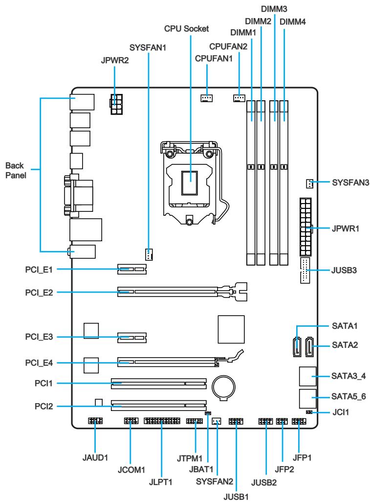
Connectors Reference Guide
| Port Name | Port Type | Page |
| Back Panel | CPU & Heatsink Installation | En-7 |
| CPU | LGA1150 CPU Socket | En-9 |
| CPUFAN1~2,SYSFAN1~3 | Fan Power Connectors | En-19 |
| DIMM1~4 | DDR3 Memory Slots | En-13 |
| JAUD1 | Front Panel Audio Connector | En-22 |
| JBAT1 | Clear CMOS Jumper | En-25 |
| JCI1 | Chassis Intrusion Connector | En-22 |
| JCOM1 | Serial Port Connector | En-23 |
| JFP1, JFP2 | System Panel Connectors | En-20 |
| JLPT1 | Parallel Port Connector | En-24 |
| JPWR1~2 | ATX Power Connectors | En-15 |
| JTPM1 | TPM Module Connector | En-23 |
| JUSB1~2 | USB 2.0 Expansion Connectors | En-21 |
| JUSB3 | USB 3.0 Expansion Connector | En-21 |
| PCI_E2,4 | PCIe x16 Expansion Slots | En-16 |
| PCI_E1,3 | PCIe x1 Expansion Slots | En-16 |
| SATA1~6 | SATA Connectors | En-18 |
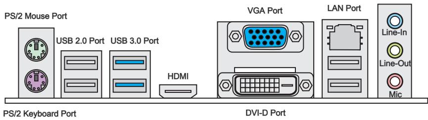
PS/2 Mouse/Keyboard Port
PS/2® mouse/ keyboard DIN connector for a PS/2® mouse/ keyboard.
USB 2.0 Port
The USB 2.0 port is for attaching USB 2.0 devices such as keyboard, mouse, or other USB 2.0-compatible devices.
USB 3.0 Port
USB 3.0 port is backward-compatible with USB 2.0 devices. It supports data transfer rate up to 5 Gbit/s (SuperSpeed).

Important
In order to use USB 3.0 devices, you must connect to a USB 3.0 port. If a USB cable is used, it must be USB 3.0 compliant.
> HDMI Port
HIGH-DEFINITION MULTIMEDIA INTERFACE
The High-Definition Multimedia Interface (HDMI) is an all-digital audio-video interface that is capable of transmitting uncompressed streams. HDMI supports all types of TV formats, including standard, enhanced, or high-definition video, plus multi-channel digital audio on a single cable.
VGA Port
The DB15-pin female connector is provided for monitor.
DVI-D Port
The DVI-D (Digital Visual Interface-Digital) connector can be connected to a LCD monitor, or a CRT monitor with an adapter. To connect a monitor, please refer to the monitor's manual for more information.
This platform supports dual-display and triple-display function.
| HDMI+VGA | HDMI+DVI | VGA+DVI | HDMI+VGA+DVI | |
| Extend mode (Extend the desktop to the second and third monitor) | ○ | ○ | ○ | ○ |
| Clone mode (Monitors have the same screen) | ○ | ○ | ○ | ○ |
LAN Port
The standard RJ-45 LAN jack is for connecting to a Local Area Network (LAN).
| LINK/ACT LED SPEED LED | LED | LED Status | Description |
| Link/ Activity LED | Off | No link | |
| Yellow | Linked | ||
| Blinking | Data activity | ||
| Speed LED | Off | 10 Mbps connection | |
| Green | 100 Mbps connection | ||
| Orange | 1 Gbps connection |
Audio Ports
These connectors are used for audio devices. The color of the jack refers to the function of the connector.
Blue-Line in: Used for connecting external audio outputting devices. - Green-Line out: Used as a connector for speakers or headphone. Pink-Mic: Used as a connector for a microphone.
Introduction to the LGA 1150 CPU
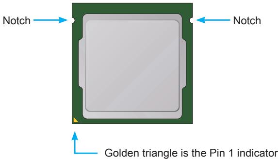
The surface of the LGA 1150 CPU has two notches and a golden triangle to assist in correctly lining up the CPU for motherboard placement. The golden triangle is the Pin 1 indicator.

Important
Overheating
Overheating can seriously damage the CPU and motherboard. Always make sure the cooling fans work properly to protect the CPU from overheating. Be sure to apply an even layer of thermal paste (or thermal tape) between the CPU and the heatsink to enhance heat dissipation.
Replacing the CPU
When replacing the CPU, always turn off the system's power supply and unplug the power supply's power cord to ensure the safety of the CPU.
Overclocking
This motherboard is designed to support overclocking. Before attempting to overclock, please make sure that all other system components can tolerate overclocking. Any attempt to operate beyond product specifications is not recommended. MSI does not guarantee the damages or risks caused by inadequate operation beyond product specifications.
CPU & Heatsink Installation
When installing a CPU, always remember to install a CPU heatsink. A CPU heatsink is necessary to prevent overheating and maintain system stability. Follow the steps below to ensure correct CPU and heatsink installation. Wrong installation can damage both the CPU and the motherboard.

Video Demonstration
Watch the video to learn how to install CPU & heatsink at the address below.
http://youtu.be/bf5La099url

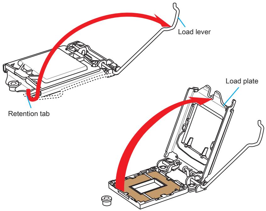
- Push the load lever down to unclip it and lift it to the fully open position.
- The load plate will automatically lift up as the load lever is pushed to the fully open position.

Important
Do not touch the socket contacts or the bottom of the CPU.
- Align the notches with the socket alignment keys. Lower the CPU straight down, without tilting or sliding the CPU in the socket. Inspect the CPU to check if it is properly seated in the socket.
- Close and slide the load plate under the retention knob. Close and engage the load lever.
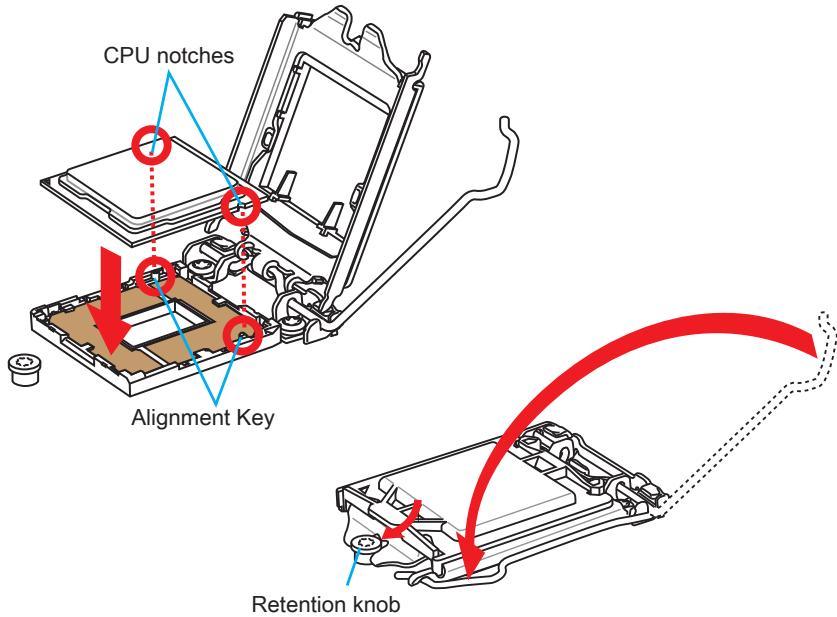
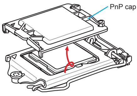
- When you press down the load lever, the PnP cap will automatically pop up from the CPU socket. Do not discard the PnP cap. Always replace the PnP cap if the CPU is removed from the socket.
- Evenly spread a thin layer of thermal paste (or thermal tape) on the top of the CPU. This will help in heat dissipation and prevent CPU overheating.
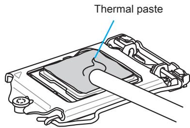
- Locate the CPU fan connector on the motherboard.
- Place the heatsink on the motherboard with the fan's cable facing towards the fan connector and the fasteners matching the holes on the motherboard.
CPU fan connector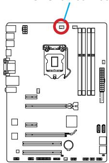
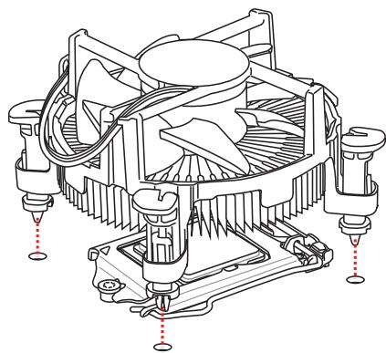
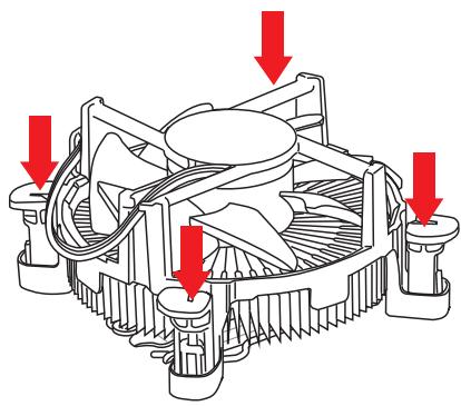
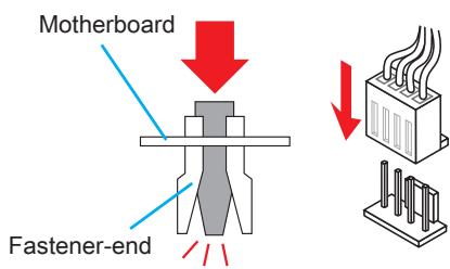
- Push down the heatsink until the four fasteners get wedged into the holes on the motherboard. Press the four fasteners down to fasten the heatsink. As each fastener locks into position, a click should be heard.
- Inspect the motherboard to ensure that the fastener-ends have been properly locked in place.
- Finally, attach the CPU fan cable to the CPU fan connector on the motherboard.

Important
- Confirm that the CPU heatsink has formed a tight seal with the CPU before booting your system.
- Whenever the CPU is not installed, always protect the CPU socket pins by covering the socket with the plastic cap.
- If you purchased a separate CPU and heatsink/cooler, please refer to the documentation in the heatsink/cooler package for more details about installation.
Memory
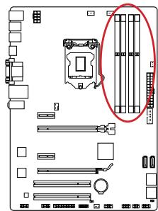
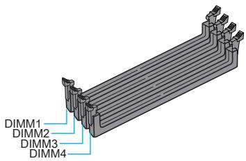
These DIMM slots are used for installing memory modules. For more information on compatible components, please visit http://www.msi.com/service/test-report/

Video Demonstration
Watch the video to learn how to install memories at the address below. http://youtu.be/76yLtJaKICQ

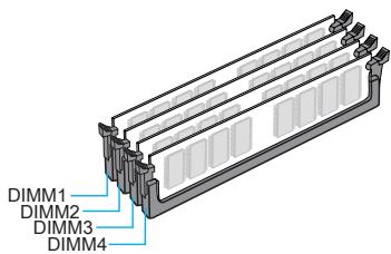
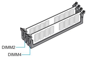
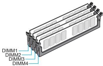
Dual-Channel mode Population Rule
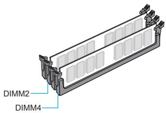
In Dual-Channel mode, the memory modules can transmit and receive data with two data bus channels simultaneously. Enabling Dual-Channel mode can enhance system performance. The following illustrations explain the population rules for Dual-Channel mode.

Important
- DDR3 memory modules are not interchangeable with DDR2, and the DDR3 standard is not backward compatible. Always install DDR3 memory modules in DDR3 DIMM slots.
- To ensure system stability, memory modules must be of the same type and density in Dual-Channel mode.
- Due to chipset resource usage, the system will only detect up to 31+ GB of memory (not full 32 GB) when all DIMM slots have 8GB memory modules installed.
Mounting Screw Holes
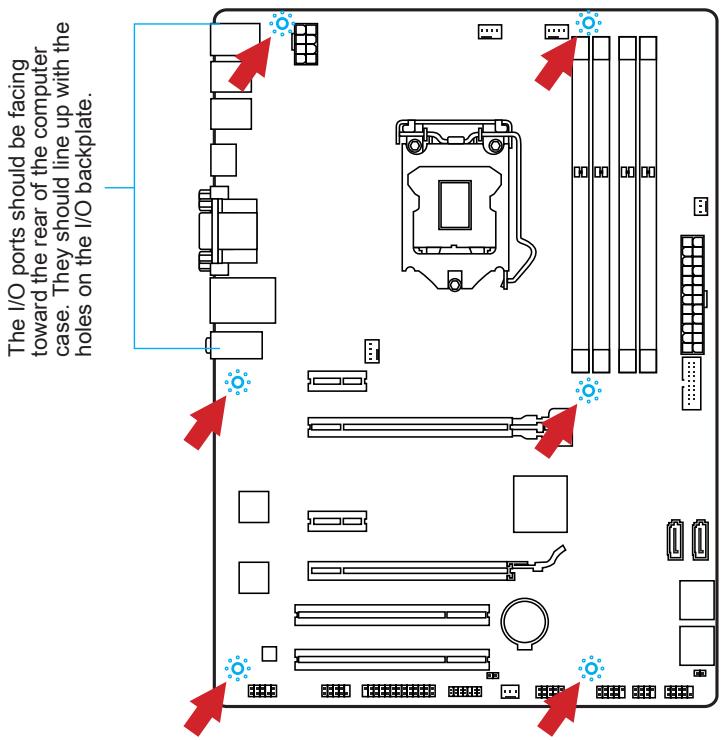
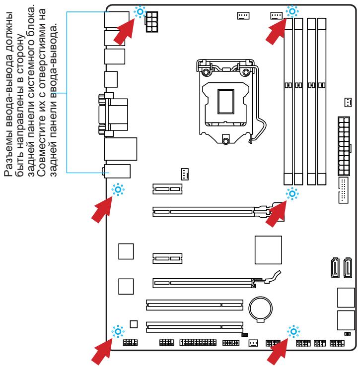
When installing the motherboard, first install the necessary mounting stands required for a motherboard on the mounting plate in your computer case. If there is an I/O back plate that came with the computer case, please replace it with the I/O backplate that came with the motherboard package. The I/O backplate should snap easily into the computer case without the need for any screws. Align the mounting plate's mounting stands with the screw holes on the motherboard and secure the motherboard with the screws provided with your computer case. The locations of the screw holes on the motherboard are shown below. For more information, please refer to the manual that came with the computer case.

Important
- Install the motherboard on a flat surface free from unnecessary debris.
- To prevent damage to the motherboard, any contact between the motherboard circuitry and the computer case, except for the mounting stands, is prohibited.
- Please make sure there are no loose metal components on the motherboard or within the computer case that may cause a short circuit of the motherboard.

Video Demonstration
Watch the video to learn how to install power supply connectors. http://youtu.be/gkDYyR_8314

JPWR1~2: ATX Power Connectors
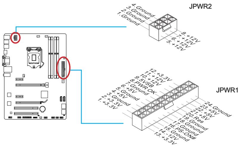
These connectors allow you to connect an ATX power supply. To connect the ATX power supply, align the power supply cable with the connector and firmly press the cable into the connector. If done correctly, the clip on the power cable should be hooked on the motherboard's power connector.

Important
Make sure that all the power cables are securely connected to a proper ATX power supply to ensure stable operation of the motherboard.
Expansion Slots
This motherboard contains numerous slots for expansion cards, such as discrete graphics or audio cards.
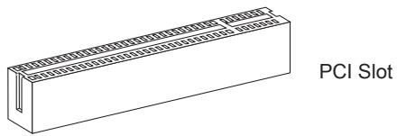
PCI_E1~4: PCIe Expansion Slots
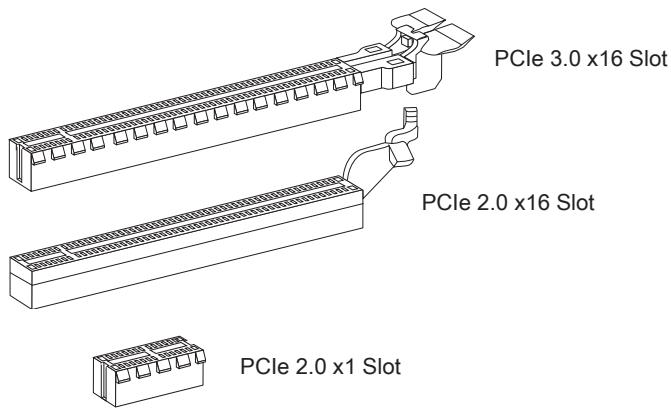
The PCIe slot supports the PCIe interface expansion card.
PCI1~2: PCI Expansion Slots
The PCI slot supports the PCI interface expansion card.

Important
When adding or removing expansion cards, always turn off the power supply and unplug the power cable from the power outlet. Read the expansion card's documentation to check for any necessary additional hardware or software changes.
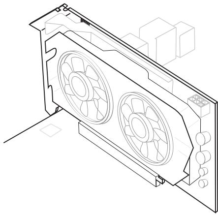
If available, this motherboard takes advantage of the CPU's integrated graphics processor, but discrete video cards can be installed by way of the motherboard's expansion slots. Adding one or more discrete video cards will significantly boost the system's graphics performance. For best compatibility, MSI graphics cards are recommended.

Video Demonstration
Watch the video to learn how to install a graphics card on PCIe x16 slot with butterfly lock.
http://youtu.be/mG0GZpr9w_A

Single Video Card Installation
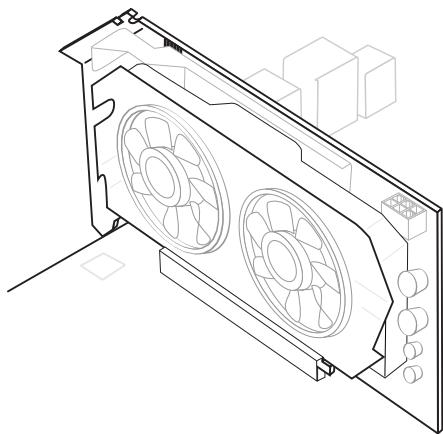
- Determine what type of expansion slot(s) the video card will use. Locate the expansion slot(s) on the motherboard. Remove any protective expansion slot covers from the computer case.
- Line up the video card on top of the expansion slot(s) with the display ports facing out of the computer case. For a single video card installation, using the PCI_E2 slot is recommended.
- Push the video card into its expansion slot(s). Depending on the expansion slot(s) used, there should be clip(s) on the expansion slot(s) that will lock in place.
- If needed, screw the edge of the graphics card to the computer case. Some video cards might require a power cable directly from the power supply.
- Please consult your video card's manual for further instructions regarding driver installation or other special settings.
SATA1~6: SATA Connectors
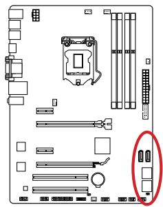
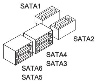
This connector is a high-speed SATA interface port. Each connector can connect to one SATA device. SATA devices include disk drives (HDD), solid state drives (SSD), and optical drives (CD/DVD/Blu-Ray).

Video Demonstration
Watch the video to learn how to install SATA HDD.
http://youtu.be/RZsMpqxythc

For Z87-G41 PC Mate/H87-G41 PC Mate
- SATA1~6 (6Gb/s, by Intel® Z87/H87)
For B85-G41 PC Mate
- SATA1, SATA2, SATA3, SATA4 (6Gb/s, by Intel® B85)
- SATA5, SATA6 (3Gb/s, by Intel® B85)

Important
- Many SATA devices also need a power cable from the power supply. Such devices include disk drives (HDD), solid state drives (SSD), and optical drives (CD / DVD / Blu-Ray). Please refer to the device's manual for further information.
- Many computer cases also require that large SATA devices, such as HDDs, SSDs, and optical drives, be screwed down into the case. Refer to the manual that came with your computer case or your SATA device for further installation instructions.
- Please do not fold the SATA cable at a 90-degree angle. Data loss may result during transmission otherwise.
- SATA cables have identical plugs on either sides of the cable. However, it is recommended that the flat connector be connected to the motherboard for space saving purposes.
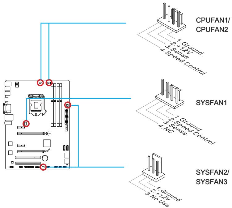
CPUFAN1~2, SYSFAN1~3: Fan Power Connectors
The fan power connectors support system cooling fans with +12V. If the motherboard has a System Hardware Monitor chipset on-board, you must use a specially designed fan with a speed sensor to take advantage of the CPU fan control. Remember to connect all system fans. Some system fans may not connect to the motherboard and will instead connect to the power supply directly. A system fan can be plugged into any available system fan connector.

Important
- Please refer to your processor's official website or consult your vendor to find recommended CPU heatsink.
- These connectors support Smart Fan Control with linear mode. The Command Center utility can be installed to automatically control the fan speeds according to the CPU's and system's temperature.
- If there are not enough ports on the motherboard to connect all system fans, adapters are available to connect a fan directly to a power supply.
- Before first boot up, ensure that there are no cables impeding any fan blades.
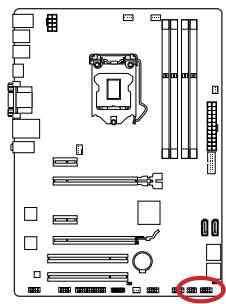
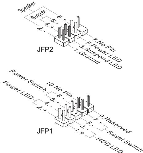
JFP1, JFP2: System Panel Connectors
These connectors connect to the front panel switches and LEDs. The JFP1 connector is compliant with the Intel® Front Panel I/O Connectivity Design Guide. When installing the front panel connectors, please use the optional M-Connector to simplify installation. Plug all the wires from the computer case into the M-Connector and then plug the M-Connector into the motherboard.

Video Demonstration
Watch the video to learn how to Install front panel connectors. http://youtu.be/DPELldVNZUI


Important
- On the connectors coming from the case, pins marked by small triangles are positive wires. Please use the diagrams above and the writing on the optional M-Connectors to determine correct connector orientation and placement.
- The majority of the computer case's front panel connectors will primarily be plugged into JFP1.
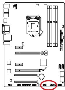
JUSB1~2: USB 2.0 Expansion Connectors
This connector is designed for connecting high-speed USB peripherals such as USB HDDs, digital cameras, MP3 players, printers, modems, and many others.
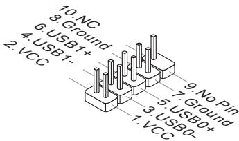

Important
Note that the VCC and GND pins must be connected correctly to avoid possible damage.
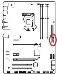
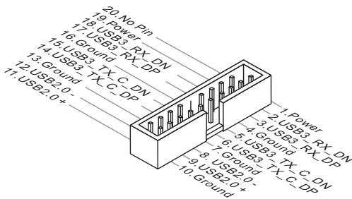
JUSB3: USB 3.0 Expansion Connector
The USB 3.0 port is backwards compatible with USB 2.0 devices. It supports data transfer rates up to 5Gbits/s (SuperSpeed).
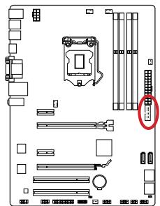
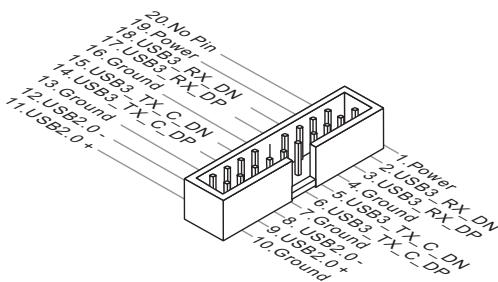

Important
- Note that the VCC and GND pins must be connected correctly to avoid possible damage.
- To use a USB 3.0 device, you must connect the device to a USB 3.0 port through an optional USB 3.0 compliant cable.
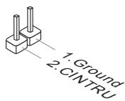
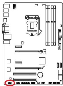
JCI1: Chassis Intrusion Connector
This connector connects to the chassis intrusion switch cable. If the computer case is opened, the chassis intrusion mechanism will be activated. The system will record this intrusion and a warning message will flash on screen. To clear the warning, you must enter the BIOS utility and clear the record.
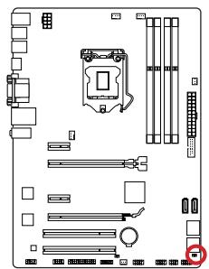
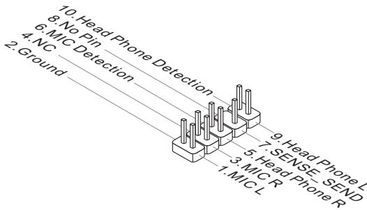
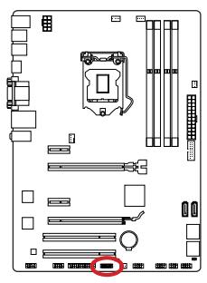
JAUD1: Front Panel Audio Connector
This connector allows you to connect the front audio panel located on your computer case. This connector is compliant with the Intel® Front Panel I/O Connectivity Design Guide.
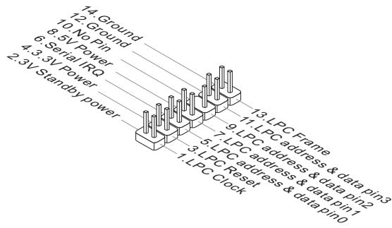
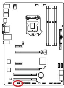
JTPM1: TPM Module Connector
This connector connects to a TPM (Trusted Platform Module). Please refer to the TPM security platform manual for more details and usages.
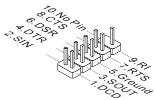
JCOM1: Serial Port Connector
This connector is a 16550A high speed communication port that sends/receives 16 bytes FIFOs. You can attach a serial device.
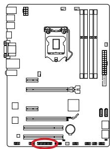
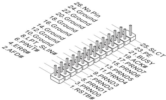
JLPT1: Parallel Port Connector
This connector is used to connect an optional parallel port bracket. The parallel port is a standard printer port that supports Enhanced Parallel Port (EPP) and Extended Capabilities Parallel Port (ECP) mode.
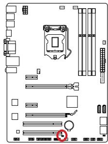
JBAT1: Clear CMOS Jumper
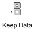
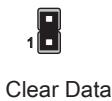
There is CMOS RAM onboard that is external powered from a battery located on the motherboard to save system configuration data. With the CMOS RAM, the system can automatically boot into the operating system (OS) every time it is turned on. If you want to clear the system configuration, set the jumpers to clear the CMOS RAM.

Important
You can clear the CMOS RAM by shorting this jumper while the system is off. Afterwards, open the jumper. Do not clear the CMOS RAM while the system is on because it will damage the motherboard.
After you install the operating system you will need to install drivers to maximize the performance of the new computer you just built. MSI motherboard comes with a Driver Disc. Drivers allow the computer to utilize your motherboard more efficiently and take advantage of any special features we provide.
You can protect your computer from viruses by installing the bundled security program. The bundle also includes a variety of powerful and creative utilities.
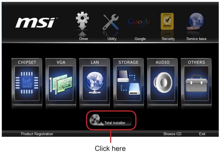
Total Installer
Total Installer is very easy to use and does a great job of finding necessary drivers. Please follow the steps below to install drivers and utilities for your new computer.
- Insert MSI Driver Disc into the optical drive. The setup screen will automatically appear if autorun is enabled in OS.
- Click Total Installer. A popup dialogue will appear listing all necessary drivers.
- Select all checkbox on driver listing dialog.
- Click Install button.
- The software installation will then be in progress, after it has finished it will prompt you to restart.
- Click OK button to finish.
- Restart your computer.
You can also use the same method to install the utilities.
BIOS Setup
CLICK BIOS is developed by MSI and provides a graphical user interface for setting BIOS parameters using the mouse and keyboard.
With CLICK BIOS, users can change BIOS settings, monitor CPU temperature, select the boot device priority, and view system information such as the CPU name, DRAM capacity, OS version, and BIOS version. Users can import and export parameter data for backup or sharing with friends.
Entering BIOS Setup
Power on the computer and the system will start the Power On Self Test (POST) process. When the message below appears on the screen, press the key to enter BIOS:
Press DEL key to enter Setup Menu, F11 to enter Boot Menu
If the message disappears before you respond and you still need to enter BIOS, restart the system by turning the computer OFF then back ON or pressing the RESET button. You may also restart the system by simultaneously pressing the Ctrl, Alt, and Delete keys.
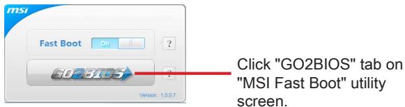
MSI additionally provides two methods to enter the BIOS setup. You can click the "GO2BIOS" tab on the "MSI Fast Boot" utility screen or press the physical "GO2BIOS" button (optional) on the motherboard to enable the system to go directly to BIOS setup at the next boot.

Important
- Please be sure to install the "MSI Fast Boot" utility before using it to enter the BIOS setup.
- The items under each BIOS category described in this chapter are under continuous update for better system performance. Therefore, the description may be slightly different from the latest BIOS and should be held for reference only.
Overview
After entering BIOS, the following screen is displayed.
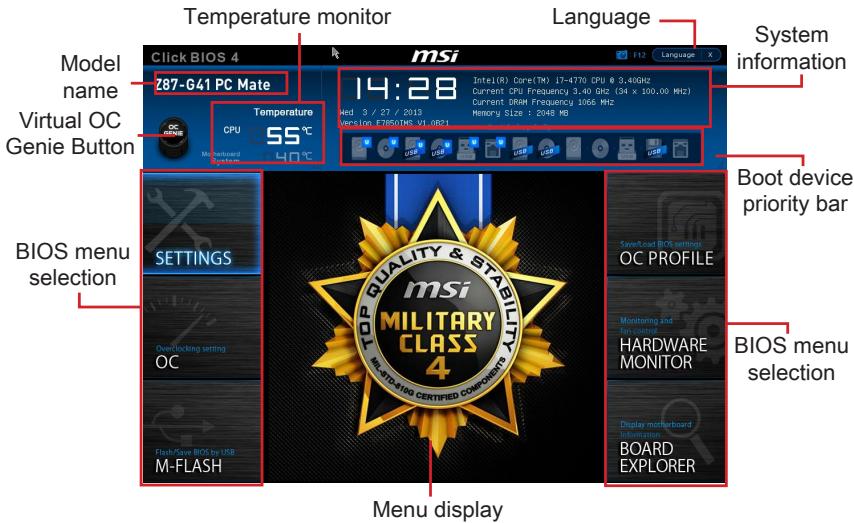
Temperature monitor Shows the temperatures of the processor and the motherboard. Language Allows you to select the language of the BIOS setup. System information Shows the time, date, CPU name, CPU frequency, DRAM frequency, DRAM capacity and the BIOS version.
BIOS menu selection
The following options are available:
- SETTINGS - Use this menu to specify the parameters for chipset and boot devices.
- OC - This menu contains the frequency and voltage adjustments. Increasing the frequency can get better performance, however high frequency and heat can cause instability, we do not recommend general users to overclock.
- M-FLASH - This menu provides the way to update BIOS with a USB flash disk. OC PROFILE - This menu is used to set various overclocking profiles.
- HARDWARE MONITOR - This menu is used to set the speeds of fans and monitor voltages of system. BOARD EXPLORER - It will provide the information of the installed devices on the motherboard.
Boot device priority bar
You can move the device icons to change the boot priority.
High priority Low priority
Menu display
This area provides BIOS settings and information to be configured.
Virtual OC Genie Button
Enables or disables the OC Genie function by clicking on this button. When enabled, this button will be light. Enabling OC Genie function can automatically overclock with MSI optimized overclocking profile.
Model Name
Shows the model name of the motherboard.
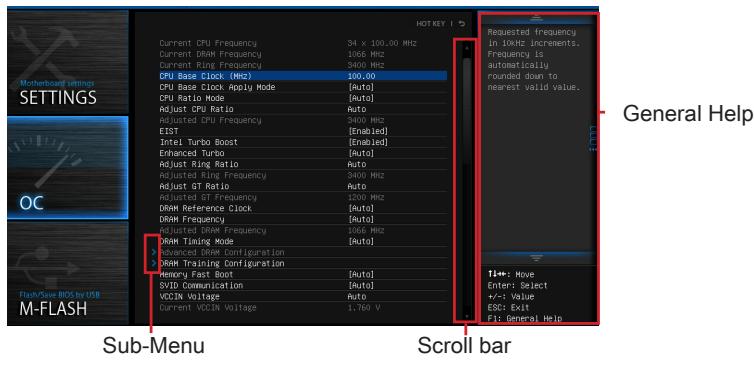
Sub-menu
If you see a point symbol to the left of certain items, it means a sub-menu can be launched for additional options. You can use the arrow keys or mouse to highlight the item and press or double-click the left mouse button to enter the sub-menu.
Scroll bar
Slide the scroll bar or use the arrow keys to display other items available in the "menu display" area.
General Help
The General Help displays a brief description to assist you in understanding the selected item.
Operation
You can control BIOS settings with the mouse and the keyboard. The following table lists and describes the hot keys and mouse operations.
| Hot key | Mouse | Description |
| <↑↓→←> | Move the cursor | Select Item |
| <Enter> | Click/ Double-click the left button | Select Icon/ Field |
| <Esc> | Click the right button | Jump to the Exit menu or return to the previous from a submenu |
| <++> | Click the right button | Increase the numeric value or make changes |
| <-> | Decrease the numeric value or make changes | |
| <F1> | General Help | |
| <F4> | CPU Specifications | |
| <F5> | Enter Memory-Z | |
| <F6> | Load optimized defaults | |
| <F8> | OC Profile Load From USB | |
| <F9> | OC Profile Save to USB | |
| <F10> | Save Change and Reset | |
| <F12> | Save a screenshot to a FAT/FAT32 USB drive |
OC Menu
This menu is for advanced users who want to overclock the mainboard.
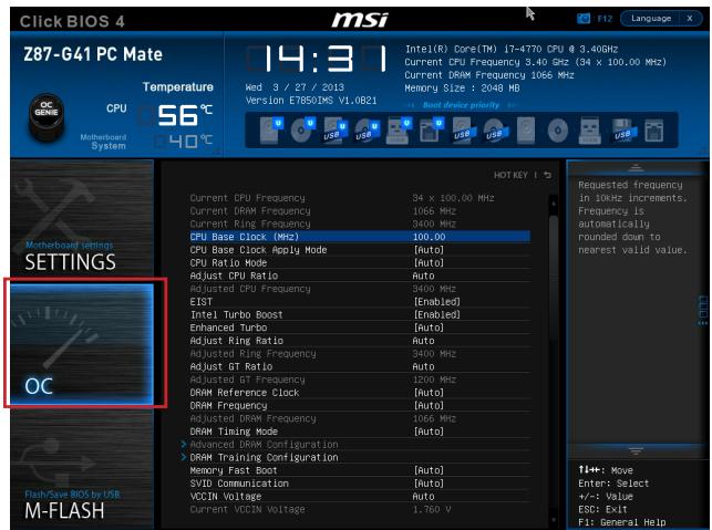

Important
- Overclocking your PC manually is only recommended for advanced users.
- Overclocking is not guaranteed, and if done improperly, can void your warranty or severely damage your hardware.
- If you are unfamiliar with overclocking, we advise you to use OC Genie for easy overclocking.
▸ Current CPU/DRAM/Ring Frequency
These items show the current frequencies of installed CPU, Memory and Ring. Read-only.
▸ CPU Base Clock (MHz) [Default]
Sets the CPU Base clock. You may overclock the CPU by adjusting this value. Please note that overclocking behavior and stability is not guaranteed. This item appears when the installed processor supports this function.
▸ Current CPU Base Clock Strap (for Z87-G41 PC Mate)
Shows the current CPU Base Clock Strap. Read only. This item can only be changed if the processor supports this function.
Adjust CPU Base Clock Strap [Auto]
Sets the CPU Base Clock Strap. You may overclock the CPU Base Clock by adjusting this value. Please note that overclocking behavior and stability is not guaranteed.
This item can only be changed if the processor supports this function. If set to "Auto", BIOS will configure this setting automatically. [Options: Auto, 1.00, 1.25, 1.67]
≻ CPU Base Clock Apply Mode [Auto]
Sets the applying mode for adjusted CPU base clock.
[Auto] This setting will be configured automatically by BIOS.
[Next Boot] CPU will run the adjusted CPU base clock after reboot.
[Immediate] CPU runs the adjusted CPU base clock immediately.
▸ CPU Ratio Mode [Auto]
Selects the CPU Ratio operating mode.
[Auto] This setting will be configured automatically by BIOS.
[Fixed Mode] Fits the CPU ratio.
[Dynamic Mode] CPU ratio will be changed dynamically according to the CPU loading.
Adjust CPU Ratio [Auto]
Sets the CPU ratio that is used to determine CPU clock speed. This item can only be changed if the processor supports this function.
Adjusted CPU Frequency
Shows the adjusted CPU frequency. Read-only.
EIST [Enabled]
Enables or disables the Enhanced Intel® SpeedStep Technology.
Intel Turbo Boost [Enabled]
Enables or disables the Intel® Turbo Boost. This item appears when the installed CPU supports this function.
[Enabled] Enables this function to boost CPU performance automatically above rated specifications when system request the highest performance state.
[Disabled] Disables this function.
Enhanced Turbo [Auto]
Enables or disables Enhanced Turbo function for all CPU cores to boost CPU performance.
[Auto] This setting will be configured automatically by BIOS.
[Enabled] All CPU cores would be increased to maximum turbo ratio.
[Disabled] Disables this function.
▸ OC Genie Switch [Gear1]
Selects a kind of overclocking profiles for OC Genie Function. This item appears when "OC Genie Function Control" sets to [By BIOS Options].
[Gear1] Enables Gear1 overclocking profile for overclocking.
[Gear2] Enables Gear2 overclocking profile for extreme overclocking.

Important
- We recommend that you do not make any modification in OC menu and do not load defaults after enabling the OC Genie function.
- Updating BIOS or clearing CMOS is not allowed in OC Genie mode, and it may cause OC Genie function fail or other effect.
Adjust Ring Ratio [Auto]
Sets the ring ratio. The valid value range depends on the installed CPU.
Adjusted Ring Frequency Shows the adjusted Ring frequency. Read-only. Adjust GT Ratio [Auto]
Sets the integrated graphics ratio. The valid value range depends on the installed CPU. Adjusted GT Frequency
Shows the adjusted integrated graphics frequency. Read-only.
DRAM Reference Clock [Auto]
Sets the DRAM reference clock. The valid value range depends on the installed CPU. This item appears when a CPU that supports this adjustment is installed.
DRAM Frequency [Auto] Sets the DRAM frequency. Please note the overclocking behavior is not guaranteed. Adjusted DRAM Frequency
Shows the adjusted DRAM frequency. Read-only.
Extreme Memory Profile (X.M.P) [Disabled]
X.M.P. (Extreme Memory Profile) is the overclocking technology by memory module. This item will be available when you install the memory modules that support X.M.P. technology.
[Disabled] Disables this function.
[Profile 1] Uses profile1 over-clocking settings of installed XMP memory module.
[Profile 2] Uses profile2 over-clocking settings of installed XMP memory module.
DRAM Timing Mode [Auto]
Selects the memory timing mode.
[Auto] DRAM timings will be determined based on SPD (Serial Presence Detect) of installed memory modules.
[Link] Allows user to configure the DRAM timing manually for all memory channel.
[UnLink] Allows user to configure the DRAM timing manually for respective memory channel.
Advanced DRAM Configuration
Press to enter the sub-menu. This sub-menu will be activated after setting [Link] or [Unlink] in "DRAM Timing Mode". User can set the memory timing for each memory channel. The system may become unstable or unbootable after changing memory timing. If it occurs, please clear the CMOS data and restore the default settings. (Refer to the Clear CMOS jumper/ button section to clear the CMOS data, and enter the BIOS to load the default settings.)
DRAM Training Configuration
Press to enter the sub-menu. Enables or disables the various training ways of DRAM. The system may become unstable or unbootable after changing these items in this sub-menu. If it occurs, please clear the CMOS data and restore the default settings. (Refer to the Clear CMOS jumper/ button section to clear the CMOS data, and enter the BIOS to load the default settings.)
Memory Fast Boot [Auto]
Enables or disables the initiation and training for memory every booting.
[Auto] This setting will be configured automatically by BIOS.
[Enabled] Memory will completely imitate the archive of first initiation and first training. After that, the memory will not be initialized and trained when booting to accelerate the system booting time.
[Disabled] The memory will be initialized and trained every booting.
SVID Communication [Auto]
Enables or disables SVID (Serial Voltage Identification) support.
[Auto] This setting will be configured automatically by BIOS.
[Enabled] PWM phase will be changed dynamically according to the CPU SVID (Serial Voltage Identification).
[Disabled] Disables SVID (Serial Voltage Identification) support.
VCCIN Voltage [Auto]
Sets the CPU input voltage. The CPU input voltage is the CPU power source that is shared with components of the CPU.
Current VCCIN Voltage
Shows current CPU VCCIN voltage. Read-only.
- CPU Core Voltage Mode/ CPU Ring Voltage Mode/ CPU GT Voltage Mode [Auto] Selects the control modes for these voltages.
[Auto] This setting will be configured automatically by BIOS.
[Adaptive Mode] Sets adaptive voltages automatically for optimizing the system performance.
[Override Mode] Allows you to set these voltages manually.
CPU Core Voltage/ CPU Ring Voltage/ CPU GT Voltage [Auto]
Sets these voltages. If set to "Auto", BIOS will set these voltages automatically or you can set it manually.
- CPU Core Voltage Offset Mode/ CPU Ring Voltage Offset Mode/ CPU GT Voltage Offset Mode/ CPU SA Voltage Offset Mode/ CPU IO Analog Voltage Offset Mode/ CPU IO Digital Voltage Offset Mode [Auto]
Selects the voltage offset modes.
[Auto] This setting will be configured automatically by BIOS.
[+] Allows you to set the positive offset voltage.
[-] Allows you to set the negative offset voltage.
- CPU Core Voltage Offset/ CPU Ring Voltage Offset/ CPU GT Voltage Offset/ CPU SA Voltage Offset/ CPU IO Analog Voltage Offset/ CPU IO Digital Voltage Offset [Auto]
Set the offset values for these voltages.
▸ Current CPU Core Voltage/ Current CPU Ring Voltage/ Current CPU GT Voltage/ Current CPU SA Voltage/ Current CPU IO Digital Voltage
Show the current voltages. Read-only.
Internal VR OVP OCP Protection [Auto]
Enables or disables the over-voltage protection and over-current protection for CPU internal VR (Voltage Regulator).
[Auto] This setting will be configured automatically by BIOS.
[Enabled] Sets the voltage limit on the CPU internal VR for over-voltage protection and over-current protection.
[Disabled] Disables this function for overclocking.
Internal VR Efficiency Management [Auto]
Enables or disables the CPU internal VR efficiency management.
[Auto] This setting will be configured automatically by BIOS.
[Enabled] Enables the VR efficiency management for power-saving control.
[Disabled] Disables this function.
▸ DRAM Voltage [Auto]
Sets the memory voltage. If set to "Auto", BIOS will set memory voltage automatically or you can set it manually.
Current DRAM Voltage
Shows current memory voltage. Read only.
▸ CPU Memory Changed Detect [Enabled]
Enables or disables the system to issue a warning message during boot when the CPU or memory has been replaced.
[Enabled] The system will issue a warning message during boot and then needs to load the default settings for new devices.
[Disabled] Disables this function and keeps the current BIOS settings.
▸ Spread Spectrum
This function reduces the EMI (Electromagnetic Interference) generated by modulating clock generator pulses.
[Enabled] Enables the spread spectrum function to reduce the EMI (Electromagnetic Interference) problem.
[Disabled] Enhances the overclocking ability of CPU Base clock.

Important
- If you do not have any EMI problem, leave the setting at [Disabled] for optimal system stability and performance. But if you are plagued by EMI, select the value of Spread Spectrum for EMI reduction.
- The greater the Spread Spectrum value is, the greater the EMI is reduced, and the system will become less stable. For the most suitable Spread Spectrum value, please consult your local EMI regulation.
- Remember to disable Spread Spectrum if you are overclocking because even a slight jitter can introduce a temporary boost in clock speed which may just cause your overclocked processor to lock up.
> CPU Specifications
Press to enter the sub-menu. This sub-menu displays the information of installed CPU. You can also access this information menu at any time by pressing [F4]. Read only.
> CPU Technology Support
Press to enter the sub-menu. The sub-menu shows what the key features does the installed CPU support. Read only.
> MEMORY-Z
Press to enter the sub-menu. This sub-menu displays all the settings and timings of installed memory. You can also access this information menu at any time by pressing [F5].
> DIMM1~4 Memory SPD
Press to enter the sub-menu. The sub-menu displays the information of installed memory. Read only.
CPU Features
Press to enter the sub-menu.
Hyper-Threading Technology [Enabled]
The processor uses Hyper-Threading technology to increase transaction rates and reduces end-user response times. Intel Hyper-Threading technology treats the multi cores inside the processor as multi logical processors that can execute instructions simultaneously. In this way, the system performance is highly improved.
[Enable] Enables Intel Hyper-Threading technology.
[Disabled] Disables this item if the system does not support HT function.
Active Processor Cores [All]
This item allows you to select the number of active processor cores.
Limit CPUID Maximum [Disabled]
Enables or disables the extended CPUID value.
[Enabled] BIOS will limit the maximum CPUID input value to circumvent boot problems with older operating systems that do not support the processor with extended CPUID value.
[Disabled] Use the actual maximum CPUID input value.
Execute Disable Bit [Enabled]
Intel's Execute Disable Bit functionality can prevent certain classes of malicious "buffer overflow" attacks where worms attempt to execute code to damage the system. It is recommended that this item be kept enabled always.
[Enabled] Enables NO-Execution protection to prevent malicious attacks and worms.
[Disabled] Disables this function.
Intel Virtualization Tech [Enabled]
Enables or disables Intel Virtualization technology.
[Enabled] Enables Intel Virtualization technology and allows a platform to run multiple operating systems in independent partitions. The system can function as multiple systems virtually.
[Disabled] Disables this function.
Hardware Prefetcher [Enabled]
Enables or disables the hardware prefetcher (MLC Streamer prefetcher).
[Enabled] Allows the hardware prefetcher to automatically pre-fetch data and instructions into L2 cache from memory for tuning the CPU performance.
[Disabled] Disables the hardware prefetcher.
Adjacent Cache Line Prefetch [Enabled]
Enables or disables the CPU hardware prefetcher (MLC Spatial prefetcher).
[Enabled] Enables adjacent cache line prefetching for reducing the cache latency time and tuning the performance to the specific application.
[Disabled] Enables the requested cache line only.
CPU AES Instructions [Enabled]
Enables or disables the CPU AES (Advanced Encryption Standard-New Instructions) support. This item appears when a CPU supports this function.
[Enabled] Enables Intel AES support.
[Disabled] Disables Intel AES support.
Intel Adaptive Thermal Monitor [Enabled]
Enables or disables the Intel adaptive thermal monitor function to protect the CPU from overheating.
[Enabled] Throttles down the CPU core clock speed when the CPU is over the adaptive temperature.
[Disabled] Disables this function.
Intel C-State [Auto]
C-state is a processor power management technology defined by ACPI.
[Auto] This setting will be configured automatically by BIOS.
[Enabled] Detects the idle state of system and reduce CPU power consumption accordingly.
[Disabled] Disable this function.
C1E Support [Disabled]
Enables or disables the C1E function for power-saving in halt state. This item appears when "Intel C-State" is enabled.
[Enabled] Enables C1E function to reduce the CPU frequency and voltage for power-saving in halt state.
[Disabled] Disables this function.
Package C State limit [Auto]
This item allows you to select a CPU C-state mode for power-saving when system is idle. This item appears when "Intel C-State" is enabled.
[Auto] This setting will be configured automatically by BIOS.
[C0~C7s] The power-saving level from high to low is C7s, C7, C6, C3, C2, then C0.
[No limit] No C-state limit for CPU.
LakeTiny Feature [Disabled]
Enables or disables Intel Lake Tiny feature with iRST for SSD. This item appears when an installed CPU supports this function and "Intel C-State" is enabled.
[Enabled] Enhances the dynamic IO load adjusted performance for accelerating the SSD speed.
[Disabled] Disables this feature.
Note: The following items will appear when "Intel Turbo Boost" is enabled.
Long Duration Power Limit (W) [Auto] Sets the long duration TDP power limit for CPU in Turbo Boost mode. Long Duration Maintained (s) [Auto] Sets the maintaining time for "Long duration power Limit(W)". Short Duration Power Limit (W) [Auto] Sets the short duration TDP power limit for CPU in Turbo Boost mode. CPU Current limit (A) [Auto]
Sets maximum current limit of CPU package in Turbo Boost mode. When the current is over the specified limit value, the CPU will automatically reduce the core frequency for reducing the current. 1/2/3/4-Core Ratio Limit [Auto]
These items only appear when a CPU that supports this function is installed. These items allow you to set the CPU ratios for different number of active cores in turbo boost mode. These items appear when the installed processor supports this function.
JPWR1~2: ATX power connectors
SATA1~6: SATA connectors
JFP1, JFP2: Front panel connectors
Current CPU/ DRAM/ Ring Frequency
Adjust CPU Base Clock Strap [Auto]
Adjust CPU Ratio [Auto]
Adjusted CPU Frequency
Adjusted GT Frequency
Adjusted DRAM Frequency
Current VCCIN Voltage
> CPU Core Voltage/ CPU Ring Voltage/ CPU GT Voltage [Auto]
> Current CPU Core Voltage/ Current CPU Ring Voltage/ Current CPU GT Voltage/ Current CPU SA Voltage/ Current CPU IO Digital Voltage
Internal VR Efficiency Management [Auto]
Current DRAM Voltage
> CPU Technology Support
> Adjacent Cache Line Prefetch [Enabled]
> Intel Adaptive Thermal Monitor [Enabled]
Intel C-State [Auto]
Long Duration Power Limit (W) [Auto]
Long Duration Maintained (s) [Auto]
Short Duration Power Limit (W) [Auto]
- CPU Current limit (A) [Auto]
Current CPU/DRAM/Ring Frequency
Current CPU Base Clock Strap (for Z87-G41 PC Mate)
Adjust CPU Base Clock Strap [Auto]
[Fixed Mode] Fix the CPU ratio.
Adjust CPU Ratio [Auto]
Adjusted CPU Frequency
Adjust Ring Ratio [Auto]
Enable or disable SVID (Serial Voltage Identification) support.
[Disabled] Disable SVID (Serial Voltage Identification) support.
VCCIN Voltage [Auto]
Current VCCIN Voltage
CPU Core Voltage/CPU Ring Voltage/CPU GT Voltage [Auto]
Current CPU Core Voltage/Current CPU Ring Voltage/Current CPU GT Voltage/Current CPU SA Voltage/Current CPU IO Digital Voltage
Internal VR Efficiency Management [Auto]
Current DRAM Voltage
CPU Technology Support
Adjacent Cache Line Prefetch [Enabled]
Enables or disables the hardware prefetcher (MLC Spatial prefetcher).
CPU AES Instructions [Enabled]
[Enabled] Enables Intel AES support.
[Disabled] Disables Intel AES support.
Intel Adaptive Thermal Monitor [Enabled]
Intel C-State [Auto]
Short Duration Power Limit (W) [Auto]
Installing the CPU Cooler
When installing the processor, be sure to install the CPU cooler. The CPU cooler prevents overheating and ensures stable system operation. Below are instructions for proper installation of the processor and CPU cooler. Improper installation may result in damage to the processor and motherboard.

Watch the Demo Video
Watch the video to learn how to install the processor and cooler: http://youtu.be/bf5La099url

Watch the video to learn how to install memory at the specified address.
http://youtu.be/76yLtJaKICQ

Fill in the blanks when using Dual-Channel mode.
In Dual-Channel mode, the memory modules can transmit and receive data simultaneously through two channels. Enabling Dual-Channel mode can increase system performance. The figures below show the rules for filling the memory slots when using Dual-Channel mode.

Attention
- DDR3 modules are not interchangeable with DDR2 modules; DDR3 does not support backward compatibility. DDR3 memory modules should be installed in DDR3 DIMM slots.
- To ensure stable system operation in Dual-Channel mode, install memory modules of the same type and capacity. Due to specific resource usage of the processor, when installing memory modules with a capacity of 8 GB in all DIMM slots, the system memory is only up to 31+ GB (not full 32 GB).
To install the motherboard on the mounting studs of the system chassis, first install the necessary mounting studs. If the system chassis package includes an I/O shield, replace it with the I/O shield that comes with the motherboard. The I/O shield is easily installed in the system chassis without screws. Align the mounting studs with the mounting holes on the motherboard and secure the motherboard with the screws provided with the system chassis. The figure below shows the location of the mounting holes for the screws. For additional information, refer to the system chassis manual.
! Attention
- Place the motherboard on a flat and dry surface. To avoid damage to the motherboard, secure electronic components on the mounting studs, and avoid contact with the system chassis. - Check the reliability of all metal components on the motherboard and inside the system chassis. Unsecured parts may cause a short circuit on the motherboard.

Video Demonstration
Watch the video to learn how to install the power connector. http://youtu.be/gkDYr_83l4

JPWR1~2: ATX Power Connectors
These connectors are designed for connecting the ATX power supply. To connect the ATX power connector, align the power cable with the connector and press it firmly. When properly connected, the latch on the power cable locks onto the connector on the motherboard.
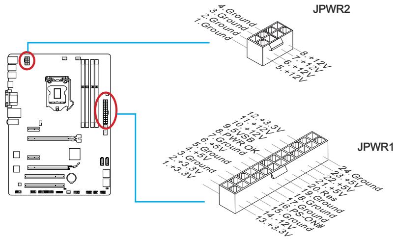

Attention
To ensure stable operation of the system board, check the reliability of all power cable connections to the corresponding ATX power supply.
Expansion Slots
Installation of Discrete Graphics Cards
Although the motherboard has integrated graphics, you can significantly improve the system's graphics performance by adding one or more discrete graphics cards to the expansion slots. For better compatibility, it is recommended to use graphics cards with MSI.

Video Demonstration
Watch the video to learn how to install a graphics card on a PCIe x16 slot with a lock.
http://youtu.be/mG0GZpr9w_A

Installing a Single Graphics Card
- Determine the expansion slot type used by the graphics card. Find the corresponding slot(s) on the motherboard. Remove the protective cover of the slot(s) from the system chassis.
- Place the graphics card over the slot(s) for expansion so that the connectors for monitors are facing the rear of the system chassis. For installing multiple graphics cards, it is recommended to use PCI_E2 slots.
- Insert the graphics card into the expansion slot(s). If the card is installed correctly, the latch(es) on the slot(s) should click into place.
- If necessary, secure the graphics card to the system chassis with screws. Some graphics cards require a direct connection to the power supply with a separate cable.
- Additional installation instructions for specific graphics cards are provided in the graphics card manuals.
SATA1~6: SATA Connectors
These connectors are high-speed SATA interfaces. Each SATA connector can connect one SATA device. SATA devices include hard drives, solid-state drives, and optical drives (CD/DVD/Blu-ray).

Video Demonstration
Watch the video to learn how to install.
SATA JeeCTKne DnCKn.
http://youtu.be/RZsMpqxthyC

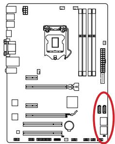

For Z87-G41 PC Mate/H87-G41 PC Mate
- SATA1~6 (6 Gb/s, based on Intel® Z87/H87)
For B85-G41 PC Mate
- SATA1, SATA2, SATA3, SATA4 (6 Gb/s, based on Intel® B85)
- SATA5, SATA6 (3 Gb/s, based on Intel® B85)

Warning
SATA devices require connection to a power supply via the power cable. Such devices include hard drives, solid-state drives, and optical drives (Compact Discs/DVDs/Blu-ray Discs). Additional information can be found in the manuals for the respective devices. - In many system cases, large SATA devices (including hard drives, solid-state drives, and optical drives) are attached using screws. For additional installation instructions, see the manuals for the system case or SATA device. - Avoid bending the SATA cable at sharp angles. Otherwise, data loss may occur during transfer. SATA cables are equipped with identical connectors on both ends. However, to save space, it is recommended that the motherboard use flat connectors.
CPUFAN1~2, SYSFAN1~3: Fan Power Connectors
Fan power connectors support fans with +12 V power. If the motherboard has a hardware monitoring chip, it is necessary to use special fans with speed sensors to utilize the fan control function. Be sure to connect all system fans. Some system fans cannot be connected to the motherboard. Instead, they connect to the power supply directly. System fans connect to available fan connectors.
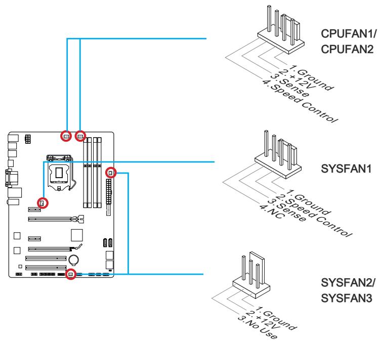

Warning
- For installation of coolers recommended for cooling the processor, refer to the official website of the processor manufacturer or to your local supplier.
- These connectors support the fan speed control function in silent mode. Install the Command Center utility for automatic control of fan speed depending on the temperature of the processor and system. In case the motherboard does not have enough connectors for connecting all system fans, fans can be connected directly to the power supply using an adapter.
- Before starting the system, make sure that the cables do not obstruct the rotation of the fans.
JFP1, JFP2: Front Panel Connectors
These connectors are used to connect the buttons and LED indicators located on the front panel. The JFP1 connector complies with the Intel® Front Panel I/O Connectivity Design standard. For ease of installation, the front panel connectors use adapter cables included in the package. Connect all the system case wires to the connectors, then connect the front panel connectors to the motherboard.

Video Demonstration
Watch the video to learn how to connect the front panel connectors.
http://youtu.be/DPELldVNZUI

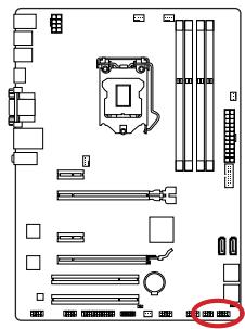
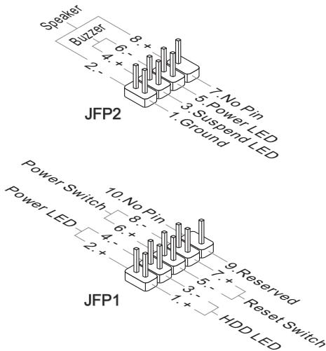

WARNING
On the connectors, the positive wires from the system case correspond to the contacts marked with small triangles. To determine the correct orientation, refer to the diagrams and labels on the additional connectors. Most of the buttons on the front panel of the system case are connected to the JFP1 connector.
JUSB1~2: USB 2.0 Expansion Connectors
These connectors are used for connecting high-speed peripheral devices such as USB hard drives, digital cameras, MP3 players, printers, modems, etc.
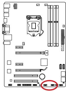
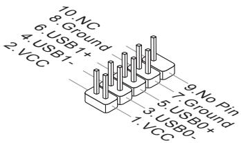

WARNING
Remember that to avoid damage, you must correctly connect the VCC and GND contacts.
JUSB3: USB 3.0 Expansion Connector
The USB 3.0 port is backward compatible with USB 2.0 devices. It supports data transfer speeds up to 5 Gb/s (SuperSpeed).

WARNING
Current CPU/ DRAM/ Ring Frequency
These items show the current status of the installed processor, memory, and Ring bus. These values cannot be changed.
CPU Base Clock (MHz) [Default]
Setting the base clock frequency. Changing this parameter provides the possibility of "overclocking". Please note that the company does not guarantee the success of overclocking and system stability. This item appears when the installed processor supports this function.
Current CPU Base Clock Strap (for Z87-G41 PC Mate)
Shows the current base clock strap. This value cannot be changed. Changing this item is possible only if the processor supports this function.
Adjust CPU Base Clock Strap [Auto]
Setting the current base clock strap. Changing this parameter provides the possibility of "overclocking" the base clock frequency. Please note that the company does not guarantee the success of overclocking and system stability. Changing this item is possible only
if the processor supports this function. If the value is set to "Auto", BIOS will automatically configure this parameter. [Options: Auto, 1.00, 1.25, 1.67]
CPU Base Clock Apply Mode [Auto]
Sets the method of applying changes or correcting the base clock frequency.
[Auto] This parameter will be configured automatically with the help of BIOS.
[Next Boot] The processor will switch to the corrected base clock frequency after reboot.
Adjust CPU Ratio [Auto]
Setting the processor multiplier for adjusting the processor clock frequency.
Changing this parameter is possible only if the processor supports this function.
Adjusted CPU Frequency
Displays the adjusted CPU frequency. This value cannot be changed.
EIST [Enabled]
Enables or disables the Enhanced Intel® SpeedStep technology.
Intel Turbo Boost [Enabled]
Enables or disables Intel® Turbo Boost. This item appears when the installed processor supports this function.
[Enabled] Enabling this function automatically increases the processor performance.
[Disabled] The function is disabled.
Enhanced Turbo [Auto]
Adjust Ring Ratio [Auto]
Sets the multiplier of the Ring bus. The range of allowable values depends on the installed processor. Adjusted Ring Frequency
Displays the adjusted Ring bus frequency. This value cannot be changed.
Adjust GT Ratio [Auto]
Sets the multiplier of the integrated graphics. The range of allowable values depends on the installed processor.
Adjusted GT Frequency
Displays the configured frequency of the integrated graphics. This value cannot be changed. ▸ DRAM Reference Clock [Auto]
Sets the reference clock for DRAM. The range of acceptable values depends on the installed processor. This item is available when a corresponding processor is installed.
▸ DRAM Frequency [Auto] Sets the memory frequency (DRAM). Note that successful overclocking is not guaranteed. Adjusted DRAM Frequency Displays the current DRAM frequency. This value cannot be changed. ▸ Extreme Memory Profile (X.M.P) [Disabled]
Current VCCIN Voltage
Displays the current CPU VCCIN voltage. This value cannot be changed.
▸ CPU Core Voltage Mode/ CPU Ring Voltage Mode/ CPU GT Voltage Mode [Auto]
▸ CPU Core Voltage/ CPU Ring Voltage/ CPU GT Voltage [Auto]
Sets the voltage. When set to "Auto", the BIOS will set the voltage automatically. You can also set the voltage manually.
- CPU Core Voltage Offset Mode/ CPU Ring Voltage Offset Mode/ CPU GT Voltage Offset Mode/ CPU SA Voltage Offset Mode/ CPU IO Analog Voltage Offset Mode/ CPU IO Digital Voltage Offset Mode [Auto]
Selects the offset voltage mode.
[Auto] The parameter will be configured automatically by the BIOS.
[+] Allows setting a positive offset voltage.
[-] Allows setting a negative offset voltage.
- CPU Core Voltage Offset/ CPU Ring Voltage Offset/ CPU GT Voltage Offset/ CPU SA Voltage Offset/ CPU IO Analog Voltage Offset/ CPU IO Digital Voltage Offset [Auto]
Allows setting the offset value for these voltages.
▸ Current CPU Core Voltage/ Current CPU Ring Voltage/ Current CPU GT Voltage/ Current CPU SA Voltage/ Current CPU IO Digital Voltage
These values are read-only. They cannot be modified.
Internal VR OVP OCP Protection [Auto]
Enables or disables the over-voltage and over-current protection for the internal voltage regulators of the processor.
[Auto] This parameter will be configured automatically with the help of the BIOS.
[Enabled] Sets the voltage limits on the internal regulators of the processor voltage to protect against over-voltage and over-current.
[Disabled] Disables the function.
Internal VR Efficiency Management [Auto]
Enables or disables the efficiency management of the internal voltage regulators of the processor.
[Auto] This parameter will be configured automatically with the help of the BIOS.
[Enabled] Enables the efficiency management of the regulators to control power saving.
[Disabled] Disables the function.
▸ DRAM Voltage [Auto]
Sets the memory voltage. If the value is set to "Auto", the BIOS sets the voltage on the memory automatically. You can also set it manually.
Current DRAM Voltage
This value is set by the system and cannot be modified.
CPU Memory Changed Detect [Enabled]
Enables or disables the warning messages during system boot when the CPU or memory has been changed.
[Enabled] The system will issue a warning during boot. You need to load the default settings for new devices.
[Disabled] Disables this function and keeps the current settings.
Spread Spectrum
CPU Technology Support
Press <Enter> to enter the submenu. This submenu displays the main functions supported by the installed processor. This value cannot be modified.
MEMORY-Z
Press <Enter> to enter the submenu. The submenu lists all parameters and timings of the installed memory. To view this information at any time, press [F5].
DIMM1~4 Memory SPD
Press <Enter> to enter the submenu. This submenu shows the information of the installed memory. This value cannot be modified.
CPU Features
Press <Enter> to enter the submenu.
Hyper-Threading Technology [Enabled]
The processor uses Hyper-Threading technology to increase performance. Intel Hyper-Threading technology allows each physical processor core to execute instructions simultaneously. This significantly increases system performance.
[Enable] Enables Intel Hyper-Threading technology.
[Disabled] Disables this function if the system does not support HT technology.
Active Processor Cores [All]
This item allows you to set the number of active processor cores.
Limit CPUID Maximum [Disabled]
Enable or disable the extended CPUID values.
[Enabled] The BIOS will limit the maximum CPUID input value to avoid boot problems with older operating systems that do not support processors with extended CPUID values.
[Disabled] Use the actual maximum CPUID input value.
[Disabled] Actual maximum CPUID input value.
Intel's Execute Disable Bit function helps protect against certain types of malicious attacks, such as buffer overflows, where some viruses attempt to execute code that can damage the system. It is recommended to enable this function.
[Enabled] No-Execution allows protection against malicious attacks and viruses.
[Disabled] Disables this function.
Intel Virtualization Tech [Enabled]
Intel Virtualization Technology [Enabled]
Enable or disable Intel Virtualization Technology.
[Enabled] Enables Intel Virtualization Technology and allows the platform to run multiple operating systems in independent partitions. The system can function as several systems practically.
[Disabled] Disables this function.
Hardware Prefetcher [Enabled]
Enable or disable the hardware prefetcher (MLC Streamer prefetcher).
[Enabled] Allows automatic prefetching of data and instructions from memory into the L2 cache to tune processor performance.
[Disabled] Disables the hardware prefetcher.
Adjacent Cache Line prefetch [Enabled]
Enable or disable the processor prefetcher (MLC Spatial prefetcher).
[Enabled] Enables adjacent cache line prefetching to reduce L3 cache latency and tune performance for specific usage.
[Disabled] Enables the requested cache line only.
CPU AES Instructions [Enabled]
Enable or disable support for CPU AES (Advanced Encryption Standard-New Instructions). This item appears when the processor supports these functions.
[Enabled] Enables Intel AES support.
[Disabled] Disables Intel AES support.
Intel Adaptive Thermal Monitor [Enabled]
Enabling or disabling this function to protect the processor from overheating.
[Enabled] Reduces the processor frequency when the processor exceeds the set temperature.
[Disabled] Disables the function.
Intel C-State [Auto]
C-state is a processor power management technology, defined by ACPI.
[Auto] The parameter will be configured automatically by the BIOS.
[Enabled] Determines the system idle state and significantly reduces processor power consumption.
[Disabled] Disables the function.
C1E Support [Disabled]
Enabling or disabling the C1E function for power saving in halt state. This item appears when "Intel C-State" is enabled.
[Enabled] Enables the C1E function to reduce processor frequency and voltage for power saving in halt state.
[Disabled] The function is disabled.
Package C State limit [Auto]
Long Duration Power Limit (W) [Auto]
Set the TDP power limit for the processor during the short duration in Turbo Boost mode.
Long Duration Maintained (s) [Auto]
Set the maximum time the processor can run with the power limit during Long Duration Power Limit.
Short Duration Power Limit (W) [Auto]
Set the TDP power limit for the processor during the short duration in Turbo Boost mode.
CPU Current limit (A) [Auto]
Sets the maximum current during Turbo Boost mode. When the current exceeds the specified limit, the processor will automatically reduce the core frequencies to reduce the current.
1/2/3/4-Core Ratio Limit [Auto]
These items are available only if the processor supports this function. These items allow you to set the processor multipliers in different cores in Turbo Boost mode. The items are available when the installed processor supports these functions.
Installation
This chapter provides demonstration diagrams about how to install your computer. Some of the installations also provide video demonstrations. Please link to the URL to watch it with the web browser on your phone or tablet. You may have even link to the URL by scanning the QR code.
The diagrams in this chapter are for reference only and may vary from the product you purchased.
- TRADEMARKS
- SMARTPHONE APPLICATION
- TECHNICAL SUPPORT
- SAFETY INSTRUCTIONS
- FCC-B RADIO FREQUENCY INTERFERENCE STATEMENT
- NOTICE
- CE CONFORMITY
- RADIATION EXPOSURE STATEMENT
- EUROPEAN COMMUNITY COMPLIANCE STATEMENT
- TAIWAN WIRELESS STATEMENTS
- WIRELESS EQUIPMENT WARNING STATEMENT
- JAPAN VCCI CLASS B STATEMENT
- CLASS B INFORMATION TECHNOLOGY EQUIPMENT
- KOREA WARNING STATEMENTS
- BATTERY INFORMATION
- WASTE BATTERIES PLEASE RECYCLE
- CHEMICAL SUBSTANCES INFORMATION
- ENGLISH
- DEUTSCH
- INSTALLATION/ INSTALLATION A
- IMPORTANT
- HDMI PORT
- LAN PORT
- AUDIO PORTS
- INTRODUCTION TO THE LGA 1150 CPU
- OVERHEATING
- REPLACING THE CPU
- OVERCLOCKING
- CPU & HEATSINK INSTALLATION
- VIDEO DEMONSTRATION
- MEMORY
- DUAL-CHANNEL MODE POPULATION RULE
- MOUNTING SCREW HOLES
- JPWR1~2: ATX POWER CONNECTORS
- EXPANSION SLOTS
- PCI_E1~4: PCIE EXPANSION SLOTS
- PCI1~2: PCI EXPANSION SLOTS
- SINGLE VIDEO CARD INSTALLATION
- SATA1~6: SATA CONNECTORS
- CPUFAN1~2, SYSFAN1~3: FAN POWER CONNECTORS
- JFP1, JFP2: SYSTEM PANEL CONNECTORS
- JUSB1~2: USB 2.0 EXPANSION CONNECTORS
- JUSB3: USB 3.0 EXPANSION CONNECTOR
- JCI1: CHASSIS INTRUSION CONNECTOR
- JAUD1: FRONT PANEL AUDIO CONNECTOR
- JTPM1: TPM MODULE CONNECTOR
- JCOM1: SERIAL PORT CONNECTOR
- JLPT1: PARALLEL PORT CONNECTOR
- JBAT1: CLEAR CMOS JUMPER
- TOTAL INSTALLER
- BIOS SETUP
- ENTERING BIOS SETUP
- PRESS DEL KEY TO ENTER SETUP MENU, F11 TO ENTER BOOT MENU
- OVERVIEW
- OPERATION
- OC MENU
- CPU SPECIFICATIONS
- CPU TECHNOLOGY SUPPORT
- MEMORY-Z
- DIMM1~4 MEMORY SPD
- CPU FEATURES
- HYPER-THREADING TECHNOLOGY [ENABLED]
- ACTIVE PROCESSOR CORES [ALL]
- LIMIT CPUID MAXIMUM [DISABLED]
- EXECUTE DISABLE BIT [ENABLED]
- INTEL VIRTUALIZATION TECH [ENABLED]
- JFP1, JFP2: FRONT PANEL CONNECTORS
- CURRENT CPU/ DRAM/ RING FREQUENCY
- ADJUST CPU BASE CLOCK STRAP [AUTO]
- CURRENT VCCIN VOLTAGE
- CPU CORE VOLTAGE/ CPU RING VOLTAGE/ CPU GT VOLTAGE [AUTO]
- ADJACENT CACHE LINE PREFETCH [ENABLED]
- INTEL ADAPTIVE THERMAL MONITOR [ENABLED]
- INTEL C-STATE [AUTO]
- CURRENT CPU/DRAM/RING FREQUENCY
- CURRENT CPU BASE CLOCK STRAP (FOR Z87-G41 PC MATE)
- VCCIN VOLTAGE [AUTO]
- CPU AES INSTRUCTIONS [ENABLED]
- INSTALLING THE CPU COOLER
- WATCH THE DEMO VIDEO
- FILL IN THE BLANKS WHEN USING DUAL-CHANNEL MODE
- ATTENTION
- INSTALLATION OF DISCRETE GRAPHICS CARDS
- INSTALLING A SINGLE GRAPHICS CARD
- WARNING
- CPU BASE CLOCK (MHZ) [DEFAULT]
- ▸ CPU CORE VOLTAGE MODE/ CPU RING VOLTAGE MODE/ CPU GT VOLTAGE MODE [AUTO]
- ▸ CPU CORE VOLTAGE/ CPU RING VOLTAGE/ CPU GT VOLTAGE [AUTO]
- INTEL'S EXECUTE DISABLE BIT FUNCTION HELPS PROTECT AGAINST CERTAIN TYPES OF MALICIOUS ATTACKS, SUCH AS BUFFER OVERFLOWS, WHERE SOME VIRUSES ATTEMPT TO EXECUTE CODE THAT CAN DAMAGE THE SYSTEM. IT IS RECOMMENDED TO ENABLE THIS FUNCTION
- INTEL VIRTUALIZATION TECHNOLOGY [ENABLED]
- HARDWARE PREFETCHER [ENABLED]
- INSTALLATION
Brand : MSI
Model : H87M-E33
Category : Motherboard