
MS-AC22 - Computer MSI - Free user manual and instructions
Find the device manual for free MS-AC22 MSI in PDF.
| Product type | Desktop computer |
| Brand | MSI |
| Model | MS-AC22 |
| Dimensions (W x D x H) | 200 x 400 x 400 mm |
| Weight | 8 kg |
| Power supply | 230 V AC, 50/60 Hz, 200 W |
| Processor | Intel Core i5 (10th Generation) |
| RAM Memory | 8 GB DDR4 |
| Storage | 256 GB SSD |
| Operating system | Windows 10 Home |
| Connectivity | Wi-Fi 5, Bluetooth 4.2, Gigabit Ethernet |
| Ports | USB 3.0 x 4, HDMI, VGA, 3.5 mm jack |
| Main functions | Data processing, internet browsing, multimedia, office work |
| Maintenance and cleaning | Clean with a soft, dry cloth. Avoid liquid products. |
| Safety | Unplug the device before cleaning. Do not expose to moisture. |
| Spare parts and repairability | Parts available from MSI after-sales service. Repairs by a qualified technician. |
| Operating temperature | 10 °C to 35 °C |
| Operating humidity | 20 % to 80 % (non-condensing) |
| Warranty | 2 years |
| Package contents | Computer, power cable, quick start guide, keyboard and mouse (optional) |
Frequently Asked Questions - MS-AC22 MSI
User questions about MS-AC22 MSI
0 question about this device. Answer the ones you know or ask your own.
Ask a new question about this device
Download the instructions for your Computer in PDF format for free! Find your manual MS-AC22 - MSI and take your electronic device back in hand. On this page are published all the documents necessary for the use of your device. MS-AC22 by MSI.
USER MANUAL MS-AC22 MSI
Wind Top AE2240 Series All-in-One (AIO) PC
MS-AC22 (V1.X) System
CONTENTS
Copyright Notice..
Trademarks . 3
U.S. Patent Numbers..
Revision History.
Upgrade and Warranty .iv
Acquisition of Replaceable Parts.. iv
Technical Support. iv
Green Product Features
Environmental Policy
Safety Instructions vi
CE Conformity VIII
FCC-B Radio Frequency Interference Statement. viii
WEEE Statement. ix
1. Overview 1-1
Packing Contents 1-2
System Overview 1-3
System Specifications 1-9
Component Replacement & Upgrade 1-10
2. Getting Started 2-1
Safety & Comfort Tips 2-2
Having Good Working Habits 2-3
Knowing the Keyboard (Optional) 2-4
Positioning your System 2-6
Connecting Peripheral Devices 2-7
Connecting Power 2-14
3. System Operations 3-1
System Booting Setup for the first time 3-2
Creating System Recovery Disk 3-3
Network Connection under Windows 3-9
RALINK Wireless LAN Connection (Optional) 3-14
THX TruStudio PRO (Optional) 3-16
On-Screen Display (OSD). 3-19
Power Management 3-22
System Recovery 3-24
Copyright Notice
The material in this document is the intellectual property of MICRO-STAR INTERNATIONAL. We take every care in the preparation of this document, but no guarantee is given as to the correctness of its contents. Our products are under continual improvement and we reserve the right to make changes without notice.
Trademarks
All trademarks are the properties of their respective owners.
MSI is a registered trademark of Micro-Star Int'l Co., Ltd.
Intel is a registered trademark of Intel Corporation.
Realtek is a registered trademark of Realtek Semiconductor Corporation.
Sound Blaster is a registered trademark of Creative Technology Ltd.
Windows is a registered trademark of Microsoft Corporation.
THX and THX TruStudio PRO are trademarks of THX Ltd., which may be registered in some jurisdictions. All rights reserved.
U.S. Patent Numbers
4,631,603; 4,819,098; 4,907,093; 5,315,448; and 6,516,132.
This product incorporates copyright protection technology that is protected by U.S. patents and other intellectual property rights. Use of this copyright protection technology must be authorized by Macrovision, and is intended for home and other limited viewing uses only unless otherwise authorized by Macrovision. Reverse engineering or disassembly is prohibited.
Revision History
Revision
V1.0
Revision History
First Release
Date
August 2010
Upgrade and Warranty
Please note that certain components preinstalled in the product may be upgradable or replaceable by user's request. To learn more about upgrade limitation, please refer to the specifications in the User's Manual. For any further information about the product users purchased, please contact the local dealer. Do not attempt to upgrade or replace any component of the product if you are not an authorized dealer or service center, since it may cause the warranty void. It is strongly recommended that you contact the authorized dealer or service center for any upgrade or replace service.
Acquisition of Replaceable Parts
Please be noticed that the acquisition of replaceable parts (or compatible ones) of the product users purchased in certain countries or territories may be fulfilled by the manufacturer within 5 years at most since the product has been discontinued, depending on the official regulations declared at the time.
- Please contact the manufacturer via http://www.msicomputer.com/msi_user/ msi_rma/ for the detailed information about the acquisition of spare parts.
Technical Support
If a problem arises with your system and no solution can be obtained from the user's manual, please contact your place of purchase or local distributor. Alternatively, please try the following help resources for further guidance.
Visit the MSI website for FAQ, technical guide, BIOS updates, driver updates and other information via http://www.msi.com/index.php?func=service
Contact our technical staff via http://ocss.msi.com/
Green Product Features
Reduced energy consumption during use and stand-by
Limited use of substances harmful to the environment and health
Easily dismantled and recycled
Reduced use of natural resources by encouraging recycling
Extended product lifetime through easy upgrades
Reduced solid waste production through take-back policy
Environmental Policy

The product has been designed to enable proper reuse of parts and recycling and should not be thrown away at its end of life.
Users should contact the local authorized point of collection for recycling and disposing of their end-of-life products.
Visit the MSI website and locate a nearby distributor for further recycling information: http://www.msi.com/index.php?func html&name service_. worldwide.
Users may also reach us at gpgreenteam@msi.com for information regarding proper Disposal, Take-back, Recycling, and Disassembly of MSI products.
Safety Instructions

Read the safety instructions carefully and thoroughly.
All cautions and warnings on the equipment or user's manual should be noted.

Keep the User's Guide that comes with the package for future reference.

Keep this equipment away from humidity and high temperature.
Lay this equipment on a reliable flat surface before setting it up.
Make sure that the power voltage is within its safety range and has been adjusted properly to the value of 100~240V before connecting the equipment to the power outlet. Do not disable the protective earth pin from the plug. The equipment must be connected to an earthed mains socket-outlet.
Always unplug the AC power cord before installing any add-on card or module to the equipment.
Always disconnect the AC power cord or switch the wall socket off if the equipment would be left unused for a certain time to achieve zero energy consumption.

The ventilator on the enclosure is used for air convection and to prevent the equipment from overheating. Do not cover the ventilator.

Do not leave the equipment in an unconditioned environment with a storage temperature above 60^ (140°F) or below 0^ (32°F), which may damage the equipment.
NOTE: The maximum operating temperature is around 40^ .

Never pour any liquid into the opening that could damage or cause electrical shock.
Place the power cord in a way that people are unlikely to step on it. Do not place anything on the power cord.
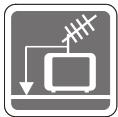
When installing the coaxial cable to the TV Tuner, it is necessary to ensure that the metal shield is reliably connected to protective earthing system of the building.
Cable distribution system should be grounded (earthed) in accordance with ANSI/NFPA 70, the National Electrical Code (NEC), in particular Section 820.93, Grounding of Outer Conductive Shield of a Coaxial Cable.

Always keep the strong magnetic or electrical objects away from the equipment.

If any of the following situations arises, get the equipment checked by service personnel:
The power cord or plug is damaged.
Liquid has penetrated into the equipment.
The equipment has been exposed to moisture.
The equipment does not work well or you can not get it work according to user's manual.
The equipment has dropped and damaged.
The equipment has obvious sign of breakage.
- The optical storage devices are classified as CLASS 1 LASER PRODUCT. Use of controls or adjustments or performance of procedures other than those specified is prohibited.
- Do not touch the lens inside the drive.

廢電池請回收
For better environmental protection, waste batteries should be collected separately for recycling or special disposal.

CAUTION:
Danger of explosion if battery is incorrectly replaced. Replace only with the same or equivalent type recommended by the manufacturer.
CE Conformity
Hereby, Micro-Star International CO., LTD declares that this device is in compliance with the essential safety requirements and other relevant provisions set out in the European Directive.

FCC-B Radio Frequency Interference Statement
This equipment has been tested and found to comply with the limits for a Class B digital device, pursuant to Part 15 of the FCC Rules. These limits are designed to provide reasonable protection against harmful interference in a residential installation. This equipment generates, uses and can radiate radio

frequency energy and, if not installed and used in accordance with the instruction manual, may cause harmful interference to radio communications. However, there is no guarantee that interference will not occur in a particular installation. If this equipment does cause harmful interference to radio or television reception, which can be determined by turning the equipment off and on, the user is encouraged to try to correct the interference by one or more of the measures listed below:
Reorient or relocate the receiving antenna.
■Increase the separation between the equipment and receiver.
Connect the equipment into an outlet on a circuit different from that to which the receiver is connected.
■Consult the dealer or an experienced radio/television technician for help.
Notice 1
The changes or modifications not expressly approved by the party responsible for compliance could void the user's authority to operate the equipment.
Notice 2
Shielded interface cables and AC power cord, if any, must be used in order to comply with the emission limits.
VOIR LA NOTICE D'INSTALLATION AVANT DE RACCORDER AU RESEAU.
This device complies with Part 15 of the FCC Rules. Operation is subject to the following two conditions:
- this device may not cause harmful interference, and
- this device must accept any interference received, including interference that may cause undesired operation.
WEEE Statement

(English) Under the European Union ("EU") Directive on Waste Electrical and Electronic Equipment, Directive 2002/96/EC, which takes effect on August 13, 2005, products of "electrical and electronic equipment" cannot be discarded as municipal waste anymore and manufacturers of covered electronic equipment will be obligated to take back such products at the end of their useful life.
The Wind Top AE2240 Series is integrated in design, selecting a stylish appearance with a glassy frame, which displays the simplicity of modern individualism and the comfort of home. Furthermore, it is accompanied with the best computer features, such as instant message, low acoustics, energy saving and 802.11 b/g/n wireless internet capability so you may roam freely in the realm of cyberspace.
PACKING CONTENTS
Wind Top Series
AC/DC Adapter
AC Power Cord

Driver/ Utility Disk
User Manual & Quick Guide

LCD Display Wiper
Keyboard (Optional)
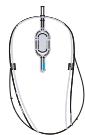
Mouse (Optional)
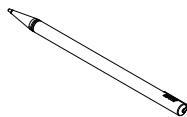
Stylus (Optional)
- Please contact us immediately if any of the items is damaged or missing.
- The illustrations are for reference only and your packing contents may slightly vary depending on the model you purchased.
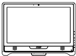
SYSTEM OVERVIEW

Front View
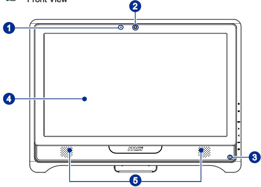
| 1 | Microphone - The built-in microphone can be used for video chatting online. |
| 2 | Webcam - The built-in webcam with the microphone can be used for picture tak- ing, video recoding, online conferencing and any other interactive ap- plications. |
| 3 | IR Receiver (Optional) - This infrared receiver is provided for remote control. |
| 4 | LCD Display - The 21.5-inch TFT LCD display is with an optimal resolution of 1920 X 1080 and standard proportion of 16:9 widenscreen. |
| 5 | Stereo Speakers - The built-in stereo speakers deliver high quality sound blaster with ste- reo system and Hi-Fi function supported. |

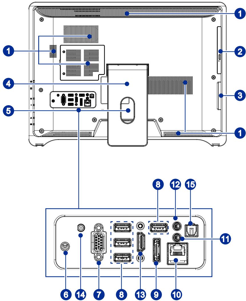
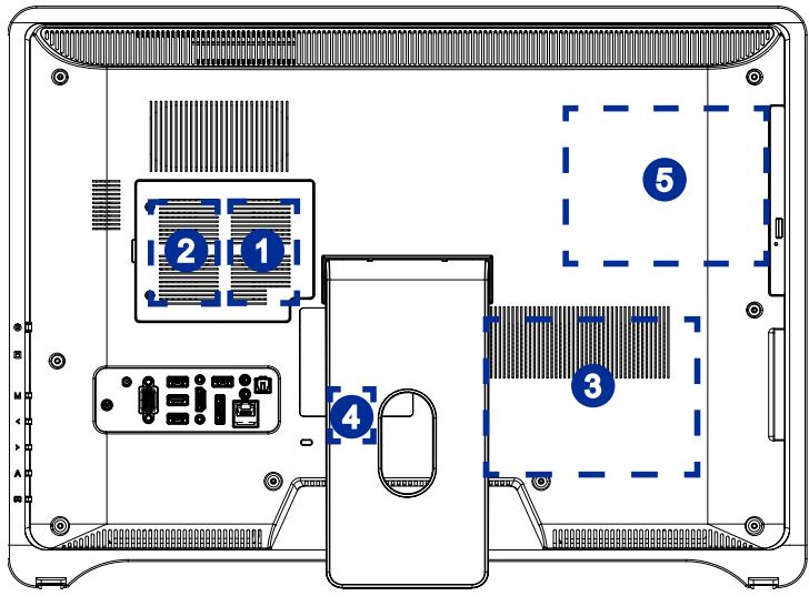
Rear View
Important
We suggest that you connect the AC/DC adapter to your AIO PC first and then connect the AC power cord to the socket-outlet for safety concerns.
| 1 | Ventilator - The ventilator on the enclosure is used for air convection and to prevent the equipment from overheating. Do not cover the ventilator. | |||
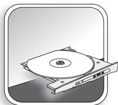
| 2 | Optical Disk Drive - A DVD Super-Multi drive is integrated for your home entertainment (Blu-ray is optional). | |||
| 3 | Card Reader Drive - The built-in card reader may support various types of memory card, such as XD (eXtreme Digital), SD (Secure Digital), SDHC (SD High Capacity), MS (Memory Stick), MS Pro (Memory Stick Pro) or MMC (Multi-Media Card) cards that usually used in devices like digital cameras, MP3 players, mobile phones and PDAs. Contact the local dealer for further information and please be noted that the supported memory cards may vary without notice. | |||
| 4 | Stand - Use this stand to position your system on a flat and stable surface. | |||
| 5 | Cable Routing Hole - Route the cables through the cable routing hole to avoid cable spaghetti when connecting devices. | |||
| 6 | Power Jack - The AC/DC adapter converts AC power to DC power for this jack. Power supplied through this jack supplies power to the PC. To prevent damage to the PC, always use the supplied AC/DC adapter. | |||
| 7 | VGA Port (Optional) - The DB15-pin female connector is provided for monitor. | |||
| 8 | USB Port - The USB (Universal Serial Bus) port is provided for attaching USB devices such as mouse, keyboard, printer, scanner, camera, PDA or other USB-compatible devices. | |||
| 9 | eSATA Port (Optional) - The eSATA (external SATA) port is provided for eSATA hard disk drives. | |||
| 10 | RJ-45 LAN Jack - The standard RJ-45 LAN jack is provided for connection to the Local Area Network (LAN). You can connect a network cable to it. Yellow——Green/ Orange | |||
| LED | Color | LED State | Condition | |
| Left | Yellow | Off | LAN link is not established. | |
| On (steady state) | LAN link is established. | |||
| On (brighter & pulsing) | The computer is communicating with another computer on the LAN. | |||
| Right | Green | Off | 10 Mbit/sec data rate is selected. | |
| On | 100 Mbit/sec data rate is selected. | |||
| Orange | On | 1000 Mbit/sec data rate is selected. | ||
| 11 | Microphone Jack - This connector is provided for microphones. | |||
| 12 | Headphone Jack - This connector is provided for headphones or speakers. | |||
| 13 | HDMI Port (Optional) - The High-Definition Multimedia Interface (HDMI) is an all-digital audio/video interface capable of transmitting uncompressed streams. HDMI supports all TV format, including standard, enhanced or high-definition video, plus multi-channel digital audio on a single cable. | |||
| 14 | TV Tuner Antenna Connector (Optional) - This connector is for TV antenna. | |||
| 15 | Optical S/PDIF-Out Jack (Optional) - This S/PDIF (Sony & Philips Digital Interconnect Format) jack is pro- vided for digital audio transmission to external speakers through an optical fiber cable. | |||

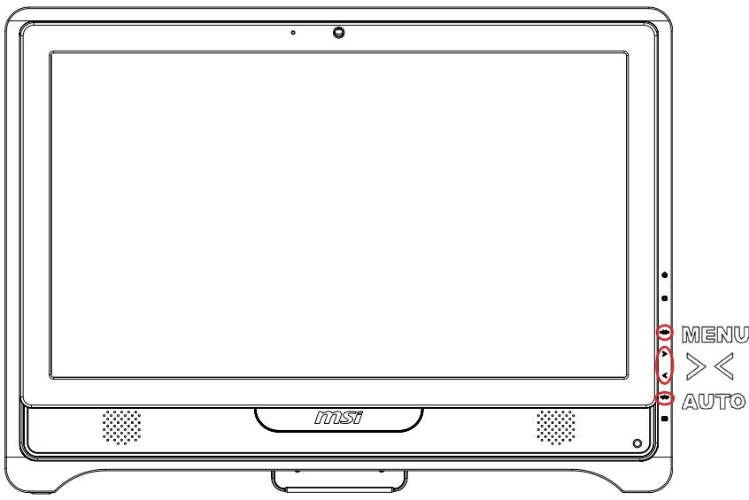
Side View
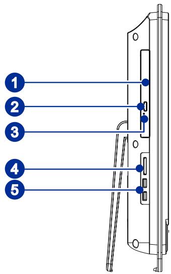
| 1 | Optical Disk Drive - A DVD Super-Multi drive is integrated for your home entertainment (Blu-ray is optional). |
| 2 | Eject Button - Press the eject button to open the optical disk drive. |
| 3 | Eject Hole - Insert a thin, straight object (such as a paper clip) into the eject hole to open the optical disk drive manually if the eject button does not work. |
| 4 | Card Reader Drive - The built-in card reader may support various types of memory card, such as XD (eXtreme Digital), SD (Secure Digital), SDHC (SD High Capacity), MS (Memory Stick), MS Pro (Memory Stick Pro) or MMC (Multi-Media Card) cards that usually used in devices like digital cameras, MP3 players, mobile phones and PDAs. Contact the local dealer for further information and please be noted that the supported memory cards may vary without notice. |
| 5 | USB Ports - The USB (Universal Serial Bus) port is provided for attaching USB devices such as mouse, keyboard, printer, scanner, camera, PDA or other USB-compatible devices. |
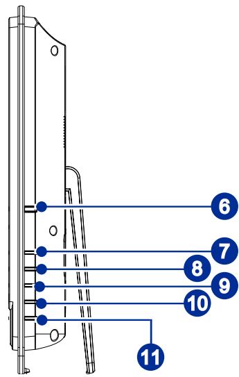
| 6 | System Power Button/ LED - Press the system power button to turn the system on or off. The power LED glows when the system is turned on and goes off when the system is shut down. In terms of power saving, the LED blinks in S3 (Suspend to RAM) mode and goes off in S4 (Suspend to Disk) mode. Pressing the system power button will wake the system up from power saving mode. |
| 7 | MENU Button MENU - Press this button to view the OSD menu or enter into the sub menu. |
| 8 | Right Button - This button indicates the cursor movement or OSD manual selection in incremental values. |
| 9 | Left Button - This button indicates the cursor movement or OSD manual selection in decremental values. |
| 10 | AUTO Button AUTO - Press this button to view the video mode menu or exit the submenu. |
| 11 | LCD Power Button - Press this button to power ON/ OFF the monitor. |
SYSTEM SPECIFICATIONS
Processor
Intel Pentium and Core™ i series processor
Chipset
Intel HM55 chipset
Memory
2 DDR3 SO-DIMM slots
Supports the maximum of 4GB
LAN
■ Wired LAN: supported by Realtek RTL8111DL Gigabit Ethernet controller
Wireless LAN: optionally supported through Mini PCI-E WLAN module
Audio
HDA Codec by Realtek ALC662
Compliant with Azalia 1.0 specs
Display
21.5-inch TFT LCD display with an optimal resolution of 1920 X 1080 and standard proportion of 16:9 widenscreen
Rear Panel I/O
1 DC power jack
1 VGA-In port (Optional)
4 USB ports
1 HDMI-Out port (Optional)
1 eSATA port (Optional)
1 RJ-45 LAN jack
1 microphone jack
1 headphone/ speaker jack
1 optical S/PDIF-Out jack (Optional)
Storage
Hard Disk Drive: 3.5", SATAI
Optical Disk Drive: Slim DVD Super Multi (Blu-ray is optional)
Card Reader: 4 in 1 (XD, SD, MMC, MS)
Stereo Speaker
2 Hi-Fi stereo speakers with THX TruStudio PRO (3W)
WebCam
1.3M WebCam with microphone
Power Supply
90~120 watt AC/DC adapter with active PFC
Input: 100-240V\~, 50-60Hz, 1.5A
Output: 19V 4.74A
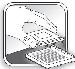
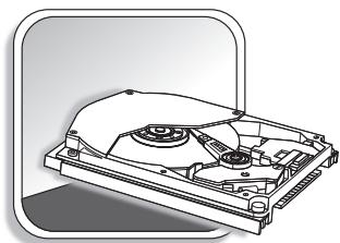
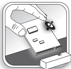
COMPONENT REPLACEMENT & UPGRADE
Please note that certain components preinstalled in the product may be upgradable or replaceable by user's request depending on the models users purchased.

Memory


CPU

Hard Disk Drive

Wireless LAN Card

Optical Disk Drive
If the specified component has been determined by the MSI engineer or store as problematic or defective and may incur the need for replacement, you may bring the product for repair along with the warranty card, purchase invoice or receipt to the MSI-authorized service center closest to your location for assistance.
To learn more about upgrade limitation, please refer to the specifications in the User's Manual. For any further information on the product users purchased, please contact the local dealer.
Do not attempt to upgrade or replace any component of the product if you are not an authorized dealer or service center, since it may cause the warranty void. It is strongly recommended that you contact the authorized dealer or service center for any upgrade or replace service.
Chapter 2 Getting Started
This chapter provides you with the information on hardware setup procedures. While connecting peripheral devices, be careful in holding the devices and use a grounded wrist strap to avoid static electricity.
SAFETY & COMFORT TIPS
The AIO PC is a portable platform that allows you to work anywhere. However, choosing a good workspace is important if you have to work with your PC for a long period of time.
- Your work area should have enough illumination.
Choose the proper desk and chair and adjust their height to fit your posture when operating. - When sitting on the chair, adjust the chair's back (if available) to support your back comfortably.
- Place you feet flat and naturally on the floor, so that your knees and elbows have the proper position (about 90-degree) when operating.
Put your hands on the desk naturally to support your wrists.
Adjust the angle/ position of the AIO PC to have an optimal view. -
Avoid using your PC in a place where discomfort may occur (such as on the bed).
The AIO PC is an electrical device. Please treat it with great care to avoid personal injury. -
Keep your hands and feet with optimal comfort.
- Adjust the angle and position of the monitor.
- Adjust the desk's height.
- Sit straight and keep a good posture.
- Adjust the chair's height.

HAVING GOOD WORKING HABITS
Having good working habits is important if you have to work with your AIO PC for long periods of time; otherwise, it may cause discomfort or injury to you. Please keep the following tips in mind when operating.
Change your posture frequently.
Stretch and exercise your body regularly.
Remember to take a break after working for a period of time.
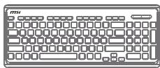
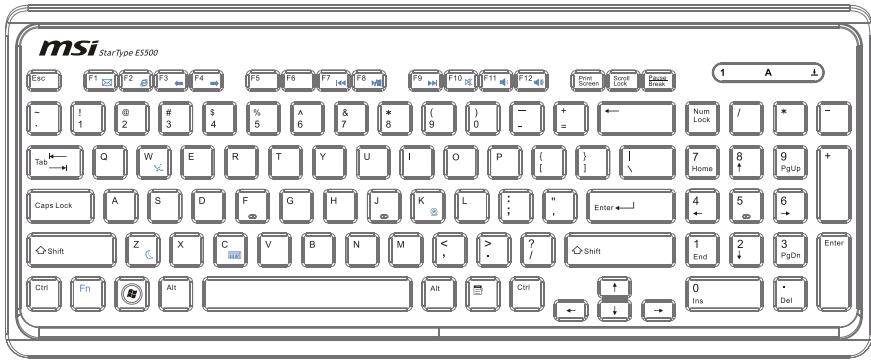
KNOWING THE KEYBOARD (OPTIONAL)
Specifications
Compatible with EU/ UK/ US/ JP/ KR language layout
Isolated keycap for easy typing
Low profile with silk printing technology
USB interface for all Windows OS
Keystroke life: 12 million
Dimensions: 376.4 (L) X 155.09 (W) X 21.91 (H) mm
Cable Length: 150cm
Weight: 440g
Features
Multimedia function keys with AIO PC
New isolated keycap for easy typing
Soft-touch and tactile feedback for comfortable typing
New concept elegant and slim keyboard in streamline shape
- Compact size for space saving
Especially fit for MSI LCD display
Compatible with Windows 2000/ ME/ XP/ Vista/ 7
Built-in function hot keys
Access favorite websites and applications with one touch hot keys
- The illustration of keyboard is for reference only. Actual product specifications may vary with territories.
Multimedia Keys
| Fn F7 | Fn + F7 | Backward to previous track |
| Fn F8 | Fn + F8 | Play and pause |
| Fn F9 | Fn + F9 | Forward to next track |
| Fn F10 | Fn + F10 | Mute function |
| Fn F11 | Fn + F11 | Volume down |
| Fn F12 | Fn + F12 | Volume up |
Hot Keys
| Fn F1 | Fn + F1 | Launch the default E-Mail applications |
| Fn F2 | Fn + F2 | Lanuch the default internet browser and go to the default home page |
| Fn F3 | Fn + F3 | Back to the previous web page |
| Fn F4 | Fn + F4 | Forward to the next web page |
| Fn C | Fn + C | Calculator |
| Fn Z | Fn + Z | Sleep mode (energy saving) |
| Fn W | Fn + W | Wireless LAN |
| Fn K | Fn + K | Camera |
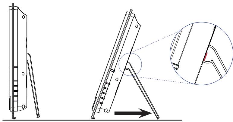
Step 1. Place your AIO PC on a flat and steady surface such as a table or desk.
Step 2. Pull the stand open and tilt the monitor. To stabilize the system, make sure that the stand has been pulled until the mark on its hinge aligns to the back of the system. Proper positioning helps to reduce your eye strain & muscle fatigue as well.
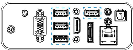
CONNECTING PERIPHERAL DEVICES
The I/O (input/output) ports on the rear panel allow you to connect peripheral devices. All devices listed here are for reference only.

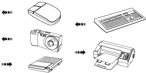
Connecting the USB Devices
This AIO PC provides USB ports for connecting various USB devices, such as mouse, keyboard, digital camera, webcam, printer, external optical storage device,... and etc. To connect these devices, install the drivers for each device first if necessary, and then connect the device to the AIO PC. This AIO PC is capable of auto detecting the USB devices installed, and if there is no detection of the devices, please manually enable the USB devices by going to Start Menu/ Control Panel / Add Hardware to add the new device.

Connecting VGA-In & HDMI-Out Devices (Optional)
This AIO PC provides a VGA port and an HDMI port for connection to external monitors, projectors, set-top boxes, DVD players, digital video cameras, mini notebooks, digital cameras, etc.
VGA (Video Graphics Array) is a graphics display system for PCs. VGA connectors and their associated cabling are always used solely to carry analog video signals along with digital clock and data.
HDMI (High Definition Multimedia Interface) is a new interface standard for PCs, displays and consumer electronics devices that supports standard, enhanced and high-definition video, plus multi-channel digital audio on a single cable.
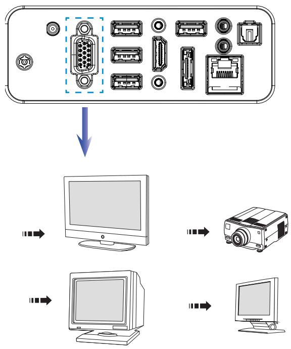
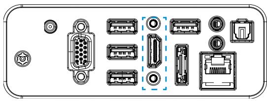

To connect the VGA/ HDMI device, first make sure the AIO PC and the targeted device are both powered off, and then connect the cable of the device to the VGA/ HDMI port of your AIO PC.

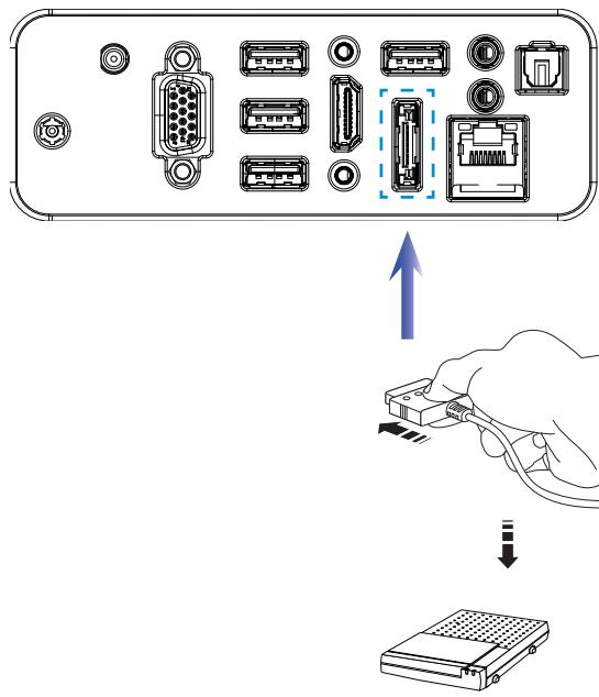
Connecting the External SATA Hard Disk Drive (Optional)
The eSATA Connector allows you to connect an external Serial ATA hard disk device. The eSATA standard interface supports "plug-and-play" technology, so that you can connect and remove the eSATA devices without turning off the AIO PC.
To connect the eSATA hard disk device, simply connect the cable of the device to the eSATA Connector of your AIO PC.

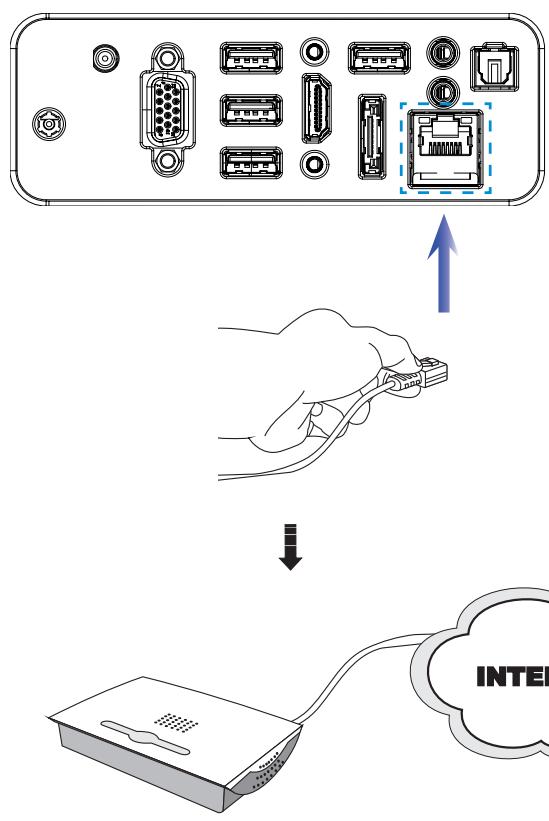
Connecting the Communication Device
Wired LAN
The RJ-45 connector of the AIO PC allows you to connect the LAN (local area network) devices, such as a hub, switch and gateway, to build a network connection.
For more instructions or detailed steps on connecting to the LAN, please ask your MIS staff or network manager for help.
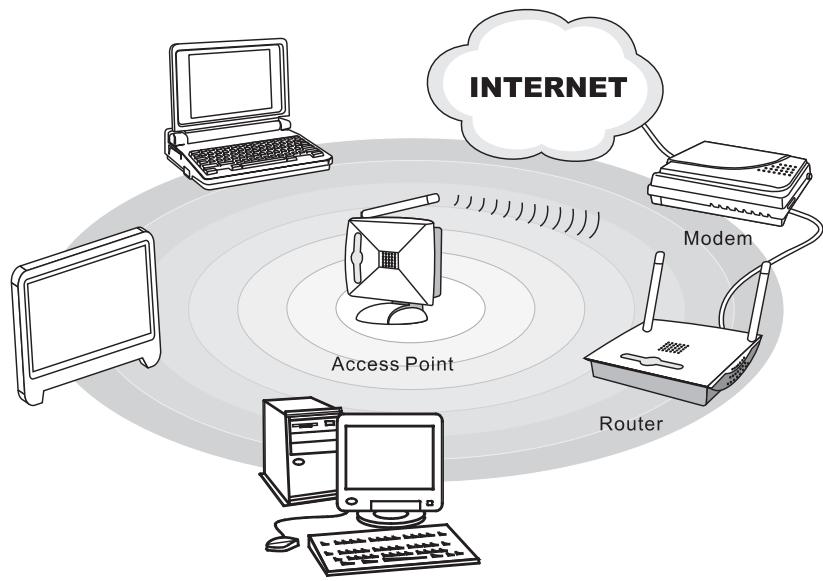
Wireless LAN (Optional)
This AIO PC is equipped with wireless LAN module which allows users to perform fast data transmission with standard IEEE 802.11 technology for wireless LAN. This gives users the mobility to move around within a broad coverage area and still be connected to the network.
By using the 64-bit/ 128-bit Wired Equivalent Privacy (WEP) encryption technology and Wi-Fi Protected Access feature, the optional built-in wireless LAN is capable to achieve a more efficient and a more secure solution to the wireless communication.
For more instructions or detailed steps on connecting to the Wireless LAN, please ask your MIS staff or network manager for help.
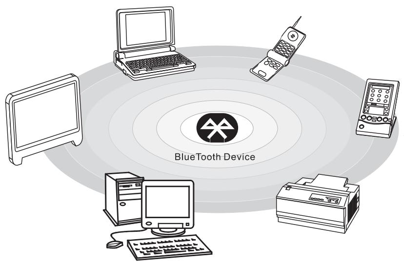
Bluetooth (Optional)
Optional USB-interfaced Bluetooth modules are available for users to establish connection with various Bluetooth-enabled devices.
Bluetooth provides a way to connect and exchange information between devices such as mobile phones, personal computers, printers, GPS receivers, PDAs, digital cameras, and video game consoles through a secure, globally unlicensed Industrial, Scientific and Medical (ISM) 2.4 GHz short-range radio frequency bandwidth.
For more instructions or detailed steps on using the Bluetooth function, please ask your MIS staff or network manager for help.
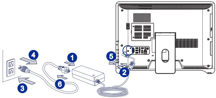
CONNECTING POWER

Connecting the AC Power
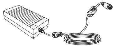
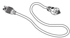
Step 1. Unpack the package to find the AC/DC adapter and AC power cord.
Step 2. Assemble the AC/DC adapter and the AC power cord.
Step 3. Plug the DC end of the adapter to the AIO PC, and the male end of the AC power cord to the electrical outlet.
Important
We suggest that you connect the AC/DC adapter to your AIO PC first and then connect the AC power cord to the socket-outlet for safety concerns.

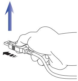
Disconnecting the AC Power
Step 4. Unplug the AC power cord from the electrical outlet first.
Step 5. Unplug the connector from the AIO PC.
Step 6. Disassemble the AC power cord and the AC/DC adapter.
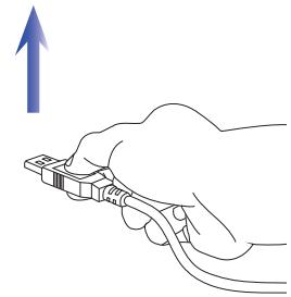
Important
When unplugging the AC power cord, always hold the connector part of the cord. Never pull the cord directly!
Chapter 3
System Operations
This chapter provides you with essential information on system operations, such as system boot setup, recovery disk creation, network connection, and so on.
Important
- It is highly recommended that you create a system recovery disk as the backup solution in the event of a catastrophic disk failure or other accidents.
- All information is subject to change without prior notice.
SYSTEM BOOTING SETUP FOR THE FIRST TIME
For the first-time use, you will need to go over the following steps to start using your Wind Top Series AIO PC. The entire booting setup will take you around 30 minutes.
Step 1. Windows setup starts running. Please wait until Windows setup finishes the progress loading.
Step 2. Select the language of the operating system and click [Next] to continue.
Step 3. Choose the "Country or region", "Time and currency", and "Keyboard layout" you need. Click [Next] to continue.
Step 4. Choose a user name for your account and name your computer to distinguish it on the network. Click [Next] to continue.
Step 5. Set a password for your account to protect your user account from unwanted users. (Leave this field blank if no need for password.) Click [Next] to continue.
Step 6. Please read the license terms. Check the "I accept the license terms" box and click [Next] to continue.
Step 7. Select [Use recommended settings] for "Help protect your computer and improve Windows automatically."
Step 8. Review your time and date settings. Click [Next] to continue.
Step 9. Please choose a wireless network you intend to join from the provided WLAN list. Click [Next] to continue. You may also click [Skip] to skip this step and set up the WLAN later.
Step 10. Followingly comes the anti-virus software screen. Click [Agree] to accept the license agreement terms and activate the anti-virus software. Alternatively, choose [No, I do not want to protect my PC.] to proceed without activating the anti-virus software.
Step 11. The "Software Installation Menu" pops up. Click [Install] to continue.
Step 12. The software is being installed. Please do not turn off the computer when software installation is running. When the progress bar completes loading, click [Finish] to continue.
Step 13. The system enters the Windows 7 OS to start its personalized settings. Get ready to explore your AIO PC after the personalized settings are done. Have fun with it!
CREATING SYSTEM RECOVERY DISK
For the first-time use, it is highly recommended that you create a system recovery disk as the backup solution in the event of a catastrophic disk failure or other accidents. Before moving forward, please make sure your system booting setup is complete and go over the following procedures to get it done.
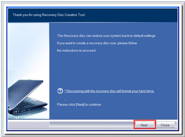
Step 1. Double-click the "BurnRecovery" icon on the desktop to launch the Recovery Disc Creation Tool. Please note that it may take a while for the operating system to prepare recovery files.

Step 2. Click [Next] to start the image creation of the recovery disk.
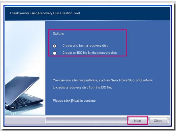
Step 3. Select [Create and burn a recovery disk] and click [Next] to continue. Alternatively, choose [Advanced] to bring forth advanced options.
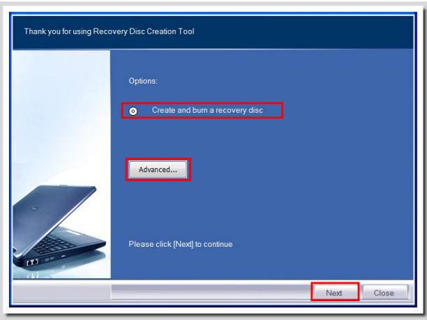
Choose between the provided options and click [Next] to continue.
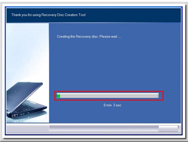
Step 4. The progress bar starts running to create the image of recovery disk. It takes some time to finish the processing.
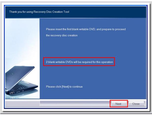
Step 5. Follow the on-screen instructions to prepare enough number of blank DVD disks. Insert the blank DVD disk into the optical disk drive and click [Next] to continue.
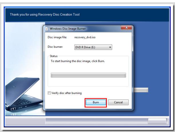
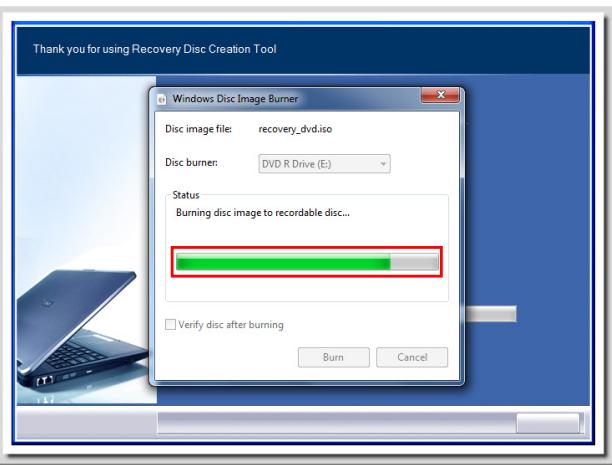
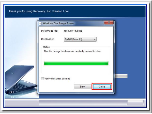
Step 6. The Windows Disc Image Burner pops up. Click [Burn] to start the burning progress. It takes a while to finish the processing.
Step 7. On completion of the disk creation, click [Close] to exit and take out the disk. Follow the on-screen instructions to create all recovery disks.
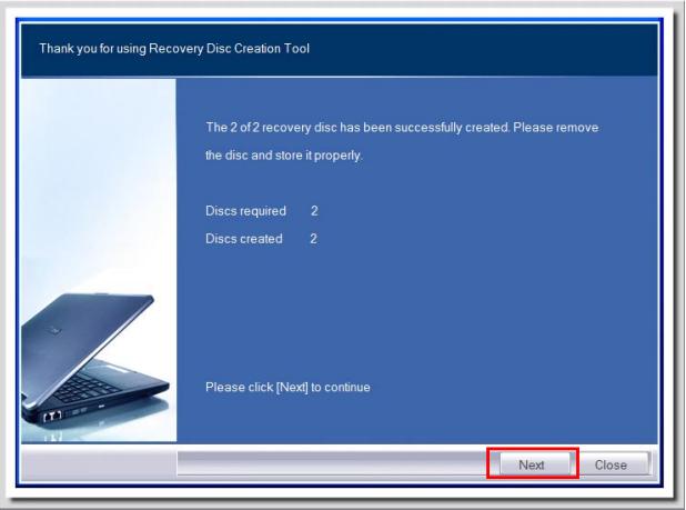
Step 8. All recovery disks have been successfully created. Please store the disks carefully and click [Next] to continue.
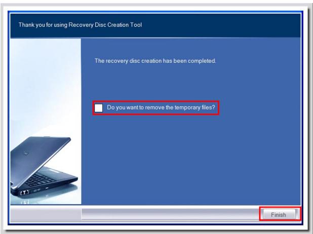
Step 9. Check the following box if you want to remove the temporary files. Click [Finish] to complete recovery disk creation.
NETWORK CONNECTION UNDER WINDOWS
Wired LAN
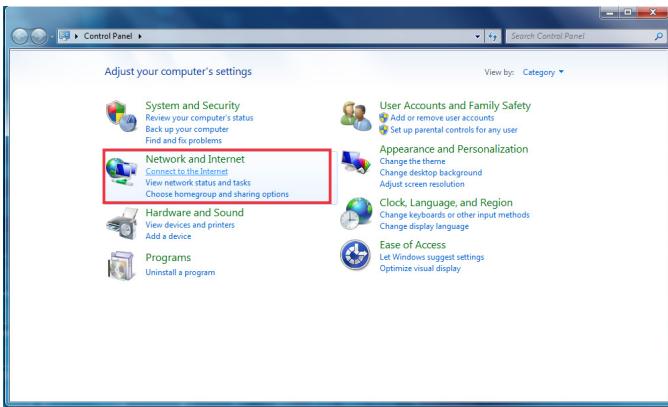
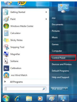
Step 1. Go to [Start] > [Control Panel].

Step 2. Select [Connect to the Internet] under [Network and Internet].
Step 3. Select [Broadband (PPPoE)] to connect using DSL or cable that requires a user name and password.
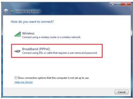
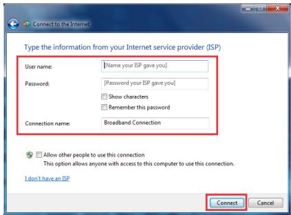
Step 4. Type the information from your Internet Service Provider (ISP) and click [Connect] to establish your LAN connection.
Wireless LAN
Step 1. Go to [Start] > [Control Panel].
Step 2. Select [Connect to the Internet] under [Network and Internet].

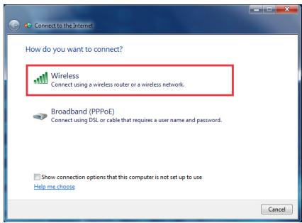
Step 3. Select [Wireless] to connect using a wireless router or a wireless network.
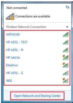
Step 4. A list of available WLAN connections pops up. Choose a connection from the list or click [Open Network and Sharing Center] to establish a new connection.
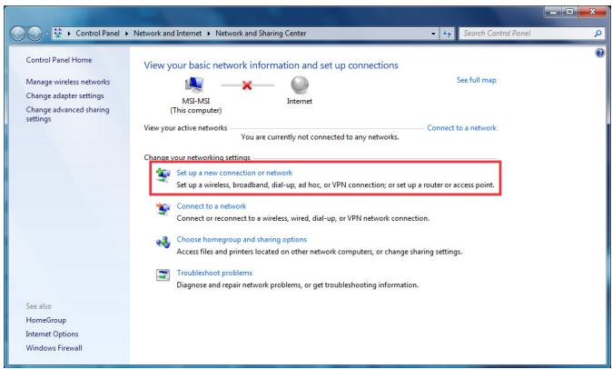
Step 5. To establish a new WLAN connection, select [Set up a new connection or network] in [Network and Sharing Center].
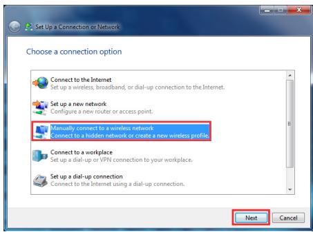
Step 6. Followingly, choose [Manually connect to a wireless network] and click [Next] to continue.
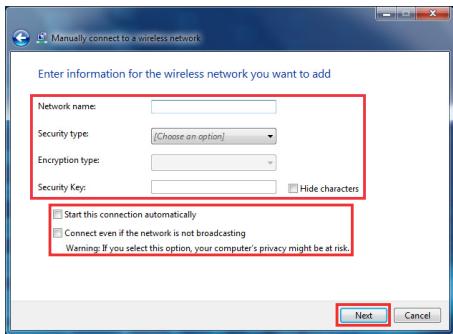
Step 7. Enter information for the wireless network you intend to add and click [Next] to proceed.
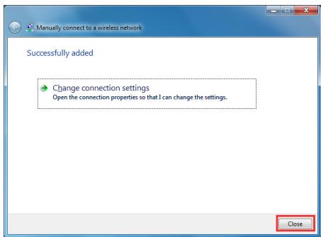
Step 8. A new WLAN connection has been made. Click [Close] to exit or select [Change connection settings] to modify the WLAN settings.
RALINK WIRELESS LAN CONNECTION (OPTIONAL)
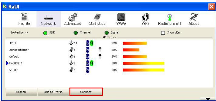
Step 1. Right-click the Ralink Wireless LAN Card status icon in the lower right corner, and then click Launch Config Utility.

Step 2. The window displays some available wireless networks. Choose a network, and then click Connect.
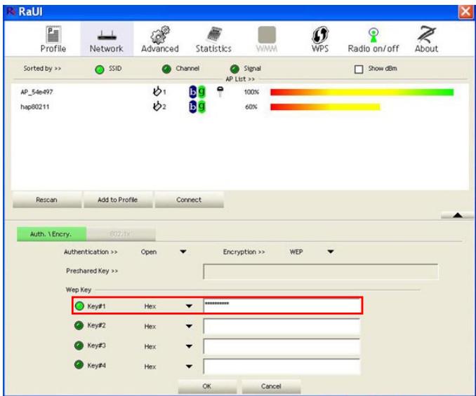
Step 3. There may prompt you to enter a key. Type the network key and then click OK.
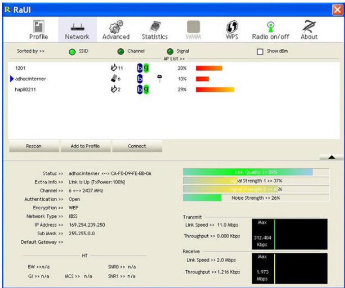
Step 4. Now, you're ready to browse the Web wirelessly.
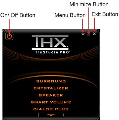
THX TRUSTUDIO PRO (OPTIONAL)
THX TruStudio PRO is specially designed to bring the same great audio experience found in live performances, films, and recording studios - to the PC. THX TruStudio provides the latest ground-breaking technologies that deliver the fullest audio experience for music, movies and games, while remaining true to the source and intention of the artists who created it.

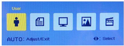
Using the THX TruStudio PRO
Step 1. To launch the THX TruStudio PRO, open its control panel from Start -> Program -> Creative -> THX TruStudio PRO or double-click the THX tray icon at the system tray.

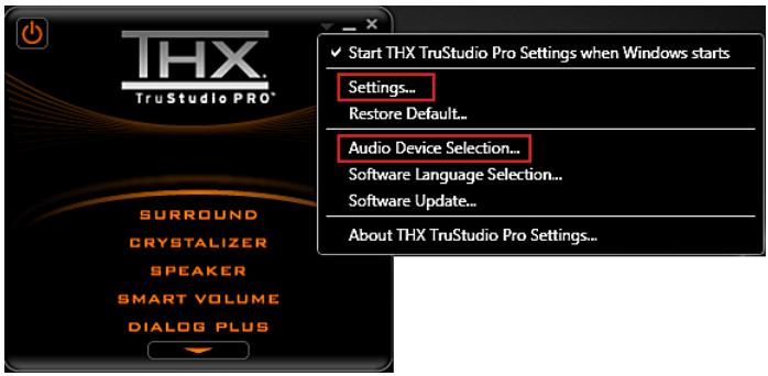
Step 2. Click the Menu Button. Enter Settings and Audio Device Selection to select and configure the audio source targeted for sound processing.
Step 3. Choose the audio effect you need and fine-tune the value to suit your preferences. The THX TruStudio PRO will process the specified audio signals to deliver enhanced audio performance.
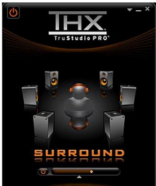
Surround controls the level of audio immersion in music, movies and games.
Instructions:
- Select Surround.
- Drag the slider left or right. Changes can be heard when adjusting the slider.
- Click the triangle under the slider to confirm the adjustment.
- Play an audio file.

Crystalizer enhances music and movies to make them sound livelier.
Instructions:
- Select Crystalizer.
- Drag the slider left or right. Changes can be heard when adjusting the slider.
- Click the triangle under the slider to confirm the adjustment.
- Play an audio file.

Speaker enhances the sound quality and bass of any speaker system for a better listening experience.
Instructions:
- Select Speaker.
- Drag the slider left or right. Changes can be heard when adjusting the slider.
- Click the triangle under the slider to confirm the adjustment.
- Play an audio file.
The bass slider will be disabled for 5.1 and 7.1 speaker configurations.

Smart Volume adjusts the loudness of your audio playback automatically to minimize sudden volume changes.
Instructions:
- Select Smart Volume.
- Drag the slider left or right. Changes can be heard when adjusting the slider.
- Click the triangle under the slider to confirm the adjustment.
- Play an audio file.
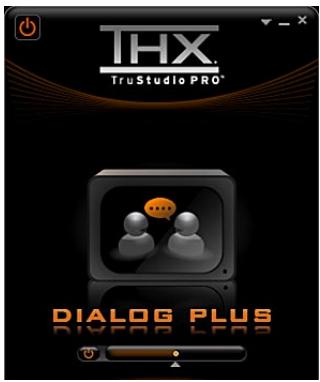
Dialog Plus enhances the voice in movies for clearer dialogs.
Instructions:
- Select Dialog Plus.
- Drag the slider left or right. Changes can be heard when adjusting the slider.
- Click the triangle under the slider to confirm the adjustment.
- Play an audio file with dialogs.
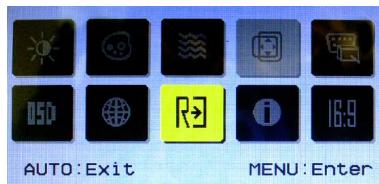
ON-SCREEN DISPLAY (OSD)
The on-screen display (OSD) allows you to tune the viewing options of the monitor, such as brightness, contrast, positioning, and language. It can be activated by buttons at the right side of the monitor.
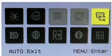
Step 1. Press the MENU button to bring up the OSD main menu. Use the Right and Left arrow buttons to select the desired function menu and press the MENU button to enter. Use the Right and Left arrow buttons to select or tune the values to suit your personal preferences. After the settings are done, press the AUTO button to exit.
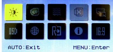
Adjusting contrast and brightness

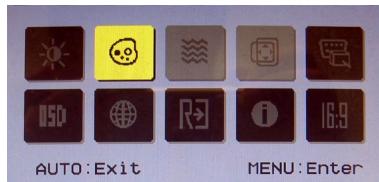
Adjusting color

Adjusting signal source
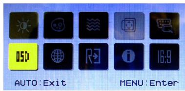
Adjusting positioning & timeout


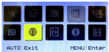
Specifying language


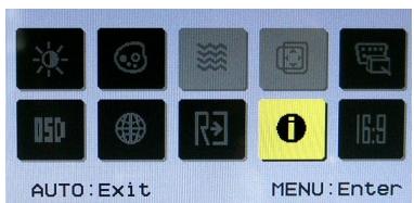
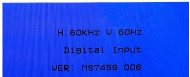
Reading system information
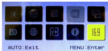
Adjusting wide screen mode

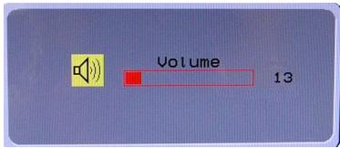
Step 2. Press the Right & Left arrow buttons to adjust the system volume.
Step 3. Press the AUTO button to view the video mode menu. Use the Right & Left arrow buttons to select a desired mode and press the AUTO button to exit after the selection is made.
POWER MANAGEMENT
Power management of personal computers (PCs) and monitors has the potential to save significant amounts of electricity as well as deliver environmental benefits.
To be energy efficient, turn off your display or set your PC to sleep mode after a period of user inactivity.
Power Management in Windows OS
- [Power Options] in Windows OS allow you to control the power management features of your display, hard drive, and battery. Go to [Start] > [Control Panel] > [System and Security].
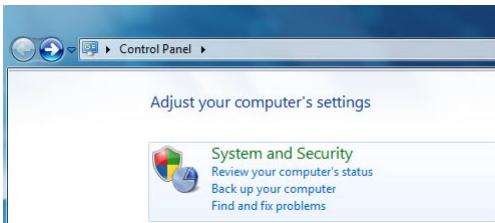
Then click on the [Power Options] link.

Power Options
Require a password when the computer wakes Change when the computer sleeps
Change what the power buttons do
Select a power plan that suits your personal needs. You may also finetune the settings by clicking [Change plan settings].
Select a power plan
Power plans can help you maximize your computer's performance or conserve energy. Make a plan active by selecting it, or choose a plan and customize it by changing its power settings. Tell me more about power plans
Preferred plans
Balanced (recommended)
Change plan settings
Automatically balances performance with energy consumption on capable hardware.
Power saver
Saves energy by reducing your computer's performance where possible.
Change plan settings
Show additional plans

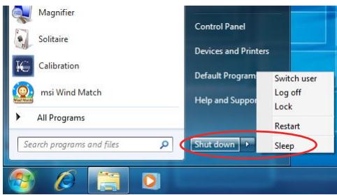
- The Shut Down Computer menu presents the options of Sleep (S3/ S4) & Shut Down (S5) for rapid and easy management of your system power.
Waking the System Up
The computer shall be able to wake up from power saving mode in response to a command from any of the following:
the power button,
the mouse,
the keyboard.

Energy Saving Tips:
- Turn off the monitor by pressing the LCD power button after a period of user inactivity.
Utilize the _n (Fn + Z) sleep mode keys to turn into power saving mode. - Tune the settings in Power Options under Windows OS to optimize your PC's power management.
Install power saving software to manage your PC's energy consumption.
Always disconnect the AC power cord or switch the wall socket off if your PC would be left unused for a certain time to achieve zero energy consumption.
SYSTEM RECOVERY
Important
The System Recovery Function is only available on systems bundled with Windows OS and MSI utilities by default.
The purposes for using the System Recovery Function may include:
- Restore the system back to the initial status of original manufacturer's default settings.
- When some errors have occurred to the operating system in use.
- When the operating system is affected by virus and is not able to work normally.
Before using the System Recovery Function, please backup the important data saved on your system drive to other storage devices.
If the following solution fails to recover your system, please contact the authorized local distributor or service center for further assistance.
Recover the System with the F3 Hotkey
If the system encounters non-recoverable problems, it is always recommended that you try the F3 hotkey to recover your system with the recovery partition of the hard disk drive first.
Follow the instructions below to continue:
- Restart the system.
- Press the F3 hotkey on the keyboard when the following image appears.

- Select [Windows Setup] from the Windows Boot Manager menu.
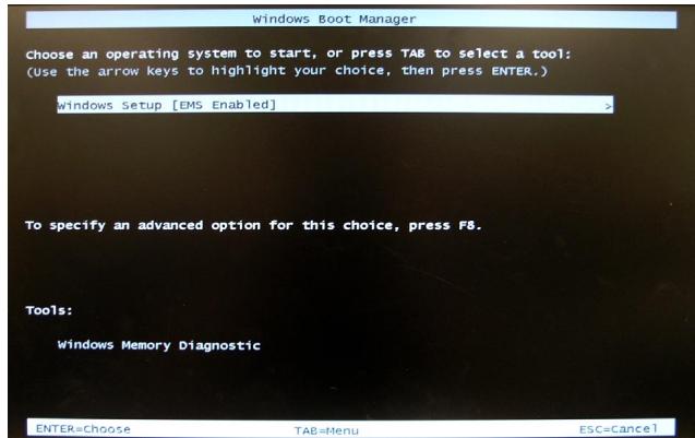
- Select [MSI Recovery Manager] to start the System Recovery Function; or select [EXIT] to restart the system.
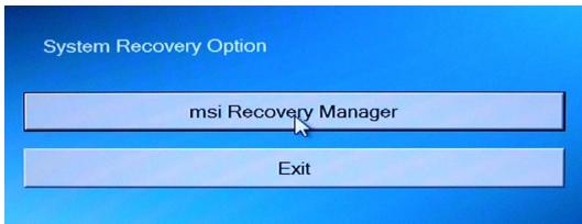
- The System Recovery Function will get your system back to default settings. Press [OK] to confirm.

- Press [OK] to reconfirm and start the System Recovery Function. Alternatively, press [Cancel] to stop.

- The System Recovery Function is proceeding now.
- The following message indicates successful system recovery. Press [OK] to restart the system and access the Windows operating system as usual.
Recovering the System with the Recovery Disks
If the F3 hotkey recovery cannot work, try recovering your system with the recovery disks that you created beforehand.
Follow the instructions below to continue:
- Insert the recovery disk into the optical disk drive and restart the system.
- Press the F11 hotkey on the keyboard when the following image appears.

- Select the [CD/DVD] device as the boot device and press [Enter] to confirm the selection.
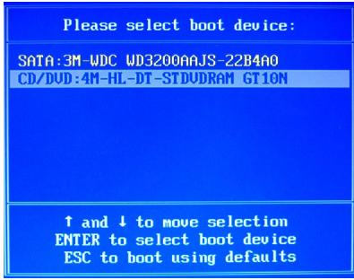
Press any key to reconfirm the selection when the following message appears.
Press any key to boot from CD or DVD ...
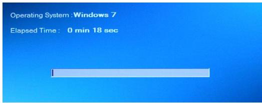
- The Windows OS starts loading files.
Windows is loading files ...
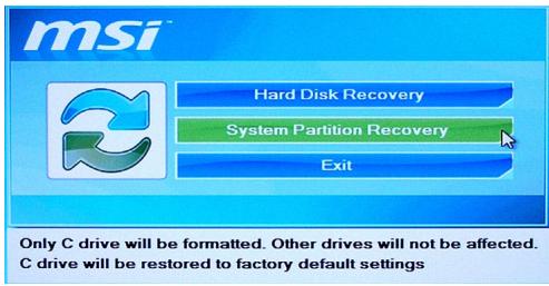
- The system recovery menu pops up. [Hard Disk Recovery] will format the whole HDD. All data on the HDD will be erased while all settings will be restored to manufacturer default. Select [Hard Disk Recovery] only when your HDD is infected with fatal viruses and no solution can be found except a clear cleanup of the HDD.
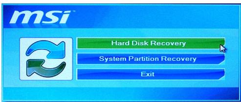
The whole hard disk will be formatted. All the data will be defragmented and restored to factory default settings.
[System Partition Recovery] will format the C drive only. Only the C drive will be restored to manufacturer default. Other drives will not be affected. It is highly recommended that users select [System Partition Recovery] to restore the system.
- The system recovery will format your HDD partition. Make sure that the important data have been backed up. Click [YES] to continue; click [NO] to stop the system recovery.
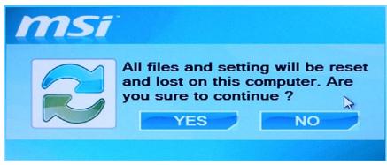
Click [YES] again to reconfirm; click [NO] to stop the system recovery.

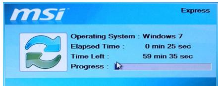
- DO NOT turn off the system power while performing the system recovery function, or it may cause unknown damage to the system.
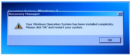
- The following message indicates successful system recovery. Press [OK] to restart the system and access the Windows operating system as usual.
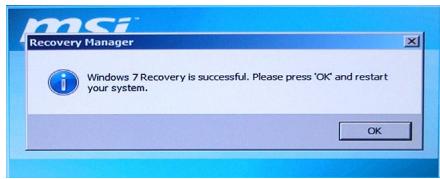
- If the recovery process is interrupted or failed, please repeat the recovery procedures from the beginning.