
GF615M-P33 - Laptop MSI - Free user manual and instructions
Find the device manual for free GF615M-P33 MSI in PDF.

| Product Type | Micro-ATX Motherboard |
| Chipset | NVIDIA® GeForce 6150SE & nForce 430 |
| Supported Processors | AMD® Phenom II / Athlon II / Sempron (socket AM3) |
| Memory | DDR3 800/1066/1333, max 8 GB, 2 DIMM slots |
| Network | Realtek® RTL8111DL 10/100/1000 (GF615M-P33) or Realtek® RTL8103EL 10/100 (GF615M-P31) |
| Audio | Realtek® ALC888S/ALC889, 7.1 channels, Azalia 1.0 compliant |
| Storage | 1 IDE port (Ultra DMA 66/100/133), 4 SATA 3Gb/s ports (RAID 0/1/5/10), 1 floppy port |
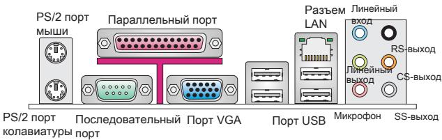
| Rear Connectors | PS/2 mouse and keyboard, COM, VGA, parallel (SPP/EPP/ECP), LAN, 4 USB 2.0, 6 audio jacks |
| Internal Connectors | 2 USB 2.0, SPDIF-Out, front audio, CD-In, TPM (optional), Chassis Intrusion, FSB overclock switch (optional) |
| Expansion Slots | 1 PCI Express x16, 1 PCI Express x1, 2 PCI (3.3V/5V) |
| Dimensions | 24.4 cm x 20.0 cm (Micro-ATX form factor) |
| Power Supply | ATX 24-pin + 4-pin, 350W power supply recommended |
| Main Features | AMD Cool'n'Quiet support, overclocking via FSB switch (10/15/20%), Dual Channel DDR3 |
| Maintenance and Cleaning | Use a dry, lint-free cloth. Avoid liquids. Disconnect before cleaning. |
| Safety | Comply with WEEE directive: do not dispose with household waste, recycle at a collection point. |
Frequently Asked Questions - GF615M-P33 MSI
User questions about GF615M-P33 MSI
0 question about this device. Answer the ones you know or ask your own.
Ask a new question about this device
Download the instructions for your Laptop in PDF format for free! Find your manual GF615M-P33 - MSI and take your electronic device back in hand. On this page are published all the documents necessary for the use of your device. GF615M-P33 by MSI.
USER MANUAL GF615M-P33 MSI
FCC-B RADIO FREQUENCY INTERFERENCE STATEMENT
This equipment has been tested and found to comply with the limits for a class B digital device, pursuant to part 15 of the FCC rules. These limits are designed
to provide reasonable protection against harmful interference in a residential installation. This equipment generates, uses and can


N1996
radiate radio frequency energy and, if not installed and used in accordance with the instruction manual, may cause harmful interference to radio communications. However, there is no guarantee that interference will occur in a particular installation. If this equipment does cause harmful interference to radio or television reception, which can be determined by turning the equipment off and on, the user is encouraged to try to correct the interference by one or more of the measures listed below.
Reorient or relocate the receiving antenna.
Increase the separation between the equipment and receiver.
Connect the equipment into an outlet on a circuit different from that to which the receiver is connected.
Consult the dealer or an experienced radio/ television technician for help.
Notice 1
The changes or modifications not expressly approved by the party responsible for compliance could void the user's authority to operate the equipment.
Notice 2
Shielded interface cables and A.C. power cord, if any, must be used in order to comply with the emission limits.
VOIR LA NOTICE D'INSTALLATION AVANT DE RACCORDER AU RESEAU.

Micro-Star International MS-7597
This device complies with Part 15 of the FCC Rules. Operation is subject to the following two conditions:
(1) this device may not cause harmful interference, and
(2) this device must accept any interference received, including interference that may cause undesired operation.
PART NUMBER
G52-75971X6
COPYRIGHT NOTICE
The material in this document is the intellectual property of MICRO-STAR INTERNATIONAL. We take every care in the preparation of this document, but no guarantee is given as to the correctness of its contents. Our products are under continual improvement and we reserve the right to make changes without notice.
TRADEMARKS
All trademarks are the properties of their respective owners.
MSI is registered trademark of Micro-Star Int'l Co., Ltd.
NVIDIA® is registered trademark of NVIDIA Corporation.
ATI® is registered trademark of ATI Technologies, Inc.
AMD is registered trademarks of AMD Corporation.
Intel is registered trademarks of Intel Corporation.
Windows® is registered trademarks of Microsoft Corporation.
AMI® is registered trademark of Advanced Micro Devices, Inc.
Award® is a registered trademark of Phoenix Technologies Ltd.
Sound Blaster® is registered trademark of Creative Technology Ltd.
Realtek® is registered trademark of Realtek Semiconductor Corporation.
■ JMicron® is registered trademark of JMicron Technology Corporation.
Netware is a registered trademark of Novell, Inc.
REVISION HISTORY
| Revision | Revision History | Date |
| V1.2 | Add a new model GF615M-P33 | May 2009 |
| V1.3 | For GF615M-P33/ P31 | December 2009 |
| V1.5 | Update JSP1 from V1.3 | July 2010 |
SAFETY INSTRUCTIONS
Always read the safety instructions carefully.
- Keep this User Manual for future reference.
- Keep this equipment away from humidity.
Lay this equipment on a reliable flat surface before setting it up.
- The openings on the enclosure are for air convection hence protects the equipment from overheating. Do not cover the openings.
- Make sure the voltage of the power source and adjust properly 110/220V before connecting the equipment to the power inlet.
- Place the power cord such a way that people can not step on it. Do not place anything over the power cord.
Always Unplug the Power Cord before inserting any add-on card or module.
All cautions and warnings on the equipment should be noted.
- Never pour any liquid into the opening that could damage or cause electrical shock.
If any of the following situations arises, get the equipment checked by a service personnel:
The power cord or plug is damaged.
Liquid has penetrated into the equipment.
The equipment has been exposed to moisture.
The equipment does not work well or you can not get it work according to User Manual.
The equipment has dropped and damaged.
The equipment has obvious sign of breakage.
- Do not leave this equipment in an environment unconditioned, storage temperature above 60^ (140^) , it may damage the equipment.
CAUTION
Danger of explosion if battery is incorrectly replaced. Replace only with the same or equivalent type recommended by the manufacturer.
警告使用者
For better environmental protection, waste batteries should be collected separately for recycling or special disposal.
ENGLISH
To protect the global environment and as an environmentalist, MSI must remind you that...
Under the European Union ("EU") Directive on Waste Electrical and Electronic Equipment, Directive 2002/96/EC, which takes effect on August 13, 2005, products of "electrical and electronic equipment" cannot be discarded as municipal waste anymore and manufacturers of covered electronic equipment will be obligated to take back

such products at the end of their useful life. MSI will comply with the product take back requirements at the end of life of MSI-branded products that are sold into the EU. You can return these products to local collection points.
DEUTSCH
Thank you for choosing the GF615M-P33/ P31 series (MS-7597 v1.x) Micro-ATX mainboard. The GF615M-P33/ P31 series is design based on NVIDIA® Geforce 6150SE & nForce 430 chipset for optimal system efficiency. Designed to fit the advanced AMD Phenom™ AM3 processor, the GF615M-P33/ P31 series deliver a high performance and professional desktop platform solution.

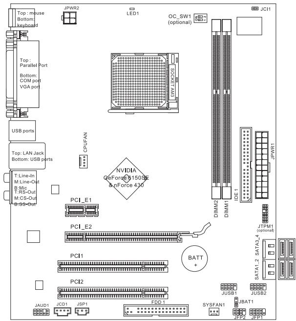
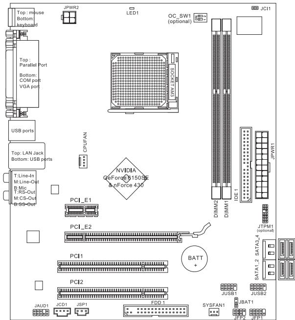
Layout
SPECIFICATIONS
Processor Support
Supports AMD Phenom II / Althon II / Sempron processors in the AM3 package.
(For the latest information about CPU, please visit
http://www.msi.com/index.php?func=cpuform2)
HyperTransport
HyperTransport 1.0
Chipset
NVIDIA® Geforce 6150SE & nForce 430 chipset
Memory Support
DDR3 800/1066/1333SDRAM(totalMax.8GB)
2 DDR3 DIMMs (240pin/ 1.5V)
(For more information on compatible components, please visit http://www.msi.
com/index.php?func=testreport)
LAN
Supports 10/100/1000 LAN by Realtek® RTL8111DL (GF615M-P33)
Or supports 10/100 LAN by Realtek® RTL8103EL (GF615M-P31)
Audio
Chip integrated by Realtek® ALC888S/ ALC889
Supports 7.1 channels audio out
Compliant with Azalia 1.0 Spec
IDE
1 IDE port
Supports Ultra DMA 66/100/133, PIO & Bus Master operation mode
SATA
4 SATA 3Gb/s ports by NVIDIA® nForce 430
RAID
SATA1~4 support RAID 0/1/5/10
Floppy
1 floppy port
Supports 1 FDD with 360 KB, 720 KB, 1.2 MB, 1.44 MB and 2.88 MB
Connectors
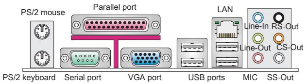
Back panel
-1PS/2 mouse port
- 1 PS/2 keyboard port
- 1 COM port
- 1 VGA port
- 1 parallel port supporting SPP/EPP/ECP mode
- 1 LAN jack
- 4 USB 2.0 Ports
- 6 flexible audio jacks
On-Board Connectors
- 2 USB 2.0 connectors
- 1 SPDIF-Out connector
- 1 Front Panel Audio connector
- 1 CD-In connector
- 1 TPM connector (optional)
- 1 Chassis Intrusion Connector
- 1 Overclock FSB Switch (optional)
Slots
1PCI Express 1.0 x16 slot
1 PCI Express 1.0 x1 slot
2 PCI slots, support 3.3V/5V PCI bus Interface
Form Factor
Micro-ATX (24.4cm X 20.0 cm)
Mounting
6 mounting holes
If you need to purchase accessories and request the part numbers, you could search the product web page and find details on our web address below http://www.msi.com/index.php
REAR PANEL
The rear panel provides the following connectors:
HARDWARE SETUP
This chapter provides you with the information about hardware setup procedures. While doing the installation, be careful in holding the components and follow the installation procedures. For some components, if you install in the wrong orientation, the components will not work properly. Use a grounded wrist strap before handling computer components. Static electricity may damage the components.
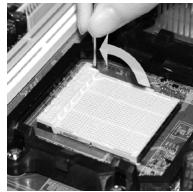
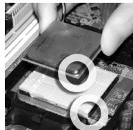
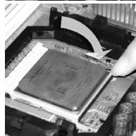
CPU & Cooler Installation for AM3
When you are installing the CPU, make sure the CPU has a cooler attached on the top to prevent overheating. Meanwhile, do not forget to apply some thermal paste on CPU before installing the heat sink/cooler fan for better heat dispersion.
Follow the steps below to install the CPU & cooler correctly. Wrong installation will cause the damage of your CPU & mainboard.
- Pull the lever sideways away from the socket. Make sure to raise the lever up to a 90-degree angle.
- Look for the gold arrow of the CPU. The gold arrow should point as shown in the picture. The CPU can only fit in the correct orientation.
- If the CPU is correctly installed, the pins should be completely embedded into the socket and can not be seen. Please note that any violation of the correct installation procedures may cause permanent damages to your mainboard.
- Press the CPU down firmly into the socket and close the lever. As the CPU is likely to move while the lever is being closed, always close the lever with your fingers pressing tightly on top of the CPU to make sure the CPU is properly and completely embedded into the socket.
- Position the cooling set onto the retention mechanism. Hook one end of the clip to hook first.
- Then press down the other end of the clip to fasten the cooling set on the top of the retention mechanism. Locate the Fix Lever and lift up it.
- Fasten down the lever.
- Attach the CPU Fan cable to the CPU fan connector on the mainboard.


IMPORTANT
- Mainboard photos shown in this section are for demonstration of the cooler installation for Socket AM3 CPUs only. The appearance of your mainboard may vary depending on the model you purchase.
- While disconnecting the Safety Hook from the fixed bolt, it is necessary to keep an eye on your fingers, because once the Safety Hook is disconnected from the fixed bolt, the fixed lever will spring back instantly.
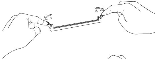
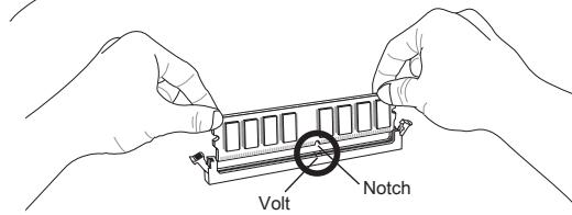
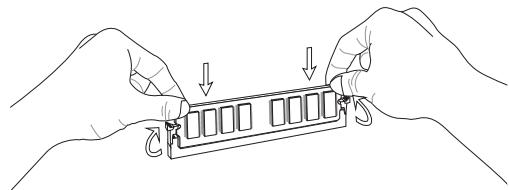
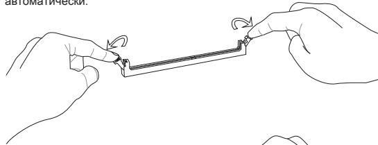
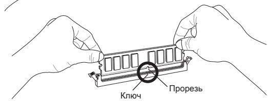
Installing Memory Modules
- The memory module has only one notch on the center and will only fit in the right orientation.
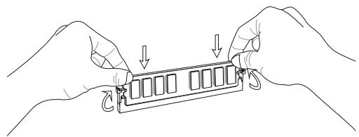
- Insert the memory module vertically into the DIMM slot. Then push it in until the golden finger on the memory module is deeply inserted in the DIMM slot. You can barely see the golden finger if the memory module is properly inserted in the DIMM slot.
- The plastic clip at each side of the DIMM slot will automatically close.
IMPORTANT
- DDR3 memory modules are not interchangeable with DDR2 and the DDR3 standard is not backwards compatible. You should always install DDR3 memory modules in the DDR3 DIMM slots.
- In Dual-Channel mode, make sure that you install memory modules of the same type and density in different channel DIMM slots.
- To enable successful system boot-up, always insert the memory modules into the DIMM1 first.
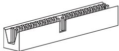
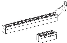
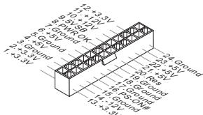
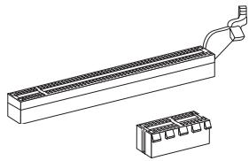
ATX 24-Pin Power Connector: JPWR1
This connector allows you to connect an ATX 24-pin power supply. To connect the ATX 24-pin power supply, make sure the plug of the power supply is inserted in the proper orientation and the pins are aligned. Then push down the power supply firmly into the connector.

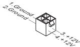
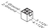
ATX 4-Pin Power Connector: JPWR2
This 12V power connector is used to provide power to the CPU.
IMPORTANT
- Make sure that all the connectors are connected to proper ATX power supplies to ensure stable operation of the mainboard.
- Power supply of 350 watts (and above) is highly recommended for system stability.
Floppy Disk Drive Connector: FDD1
This connector supports 360 KB, 720 KB, 1.2 MB, 1.44 MB or 2.88 MB floppy disk drive.

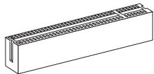
IDE Connector: IDE1
This connector supports IDE hard disk drives, optical disk drives and other IDE devices.
IMPORTANT
If you install two IDE devices on the same cable, you must configure the drives to cable select mode or separately to master / slave mode by setting jumpers. Refer to IDE device documentation supplied by the vendors for jumper setting instructions.
Serial ATA Connector: SATA1 ~ 4
This connector is a high-speed Serial ATA interface port. Each connector can connect to one Serial ATA device.
IMPORTANT
Please do not fold the Serial ATA cable into 90-degree angle. Otherwise, data loss may occur during transmission.
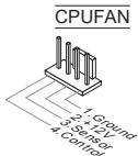
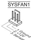
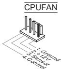
Fan Power Connectors: CPUFAN, SYSFAN1
The fan power connectors support system cooling fan with +12V . When connecting the wire to the connectors, always note that the red wire is the positive and should be connected to the +12V ; the black wire is Ground and should be connected to GND. If the mainboard has a System Hardware Monitor chipset onboard, you must use a specially designed fan with speed sensor to take advantage of the CPU fan control.
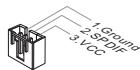
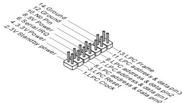
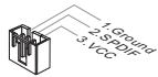
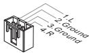
S/PDIF-Out Connector: JSP1
This connector is used to connect S/PDIF (Sony & Philips Digital Interconnect Format) interface for digital audio transmission.
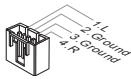
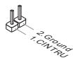
CD-In Connector: JCD1
This connector is provided for external audio input.
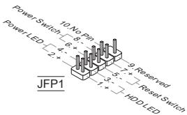
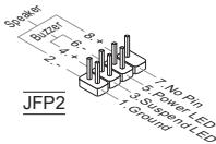
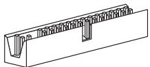
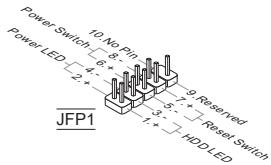
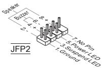
Front Panel Connectors: JFP1, JFP2
These connectors are for electrical connection to the front panel switches and LEDs. The JFP1 is compliant with Intel® Front Panel I/O Connectivity Design Guide.
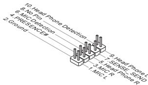
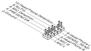
Front Panel Audio Connector: JAUD1
This connector allows you to connect the front panel audio and is compliant with Intel® Front Panel I/O Connectivity Design Guide.
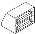
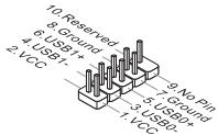
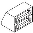
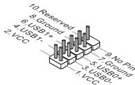
Front USB Connector: JUSB1/ JUSB2
This connector, compliant with Intel® I/O Connectivity Design Guide, is ideal for connecting high-speed USB interface peripherals such as USB HDD, digital cameras, MP3 players, printers, modems and the like.
TPM Module connector: JTPM1 (optional)
This connector connects to a TPM (Trusted Platform Module) module. Please refer to the TPM security platform manual for more details and usages.
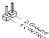
Chassis Intrusion Connector: JCI1
This connector connects to the chassis intrusion switch cable. If the chassis is opened, the chassis intrusion mechanism will be activated. The system will record this status and show a warning message on the screen. To clear the warning, you must enter the BIOS utility and clear the record.
APS LED Status Indicator:LED1
These APS (Active Phase Switching) LED indicates the current CPU power phase mode. Follow the instructions below to read.

| ON | The LED will light when CPU is in 3 phase power mode. |
| OFF | The LED off when CPU is in 1 phase power mode. |
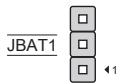
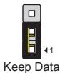
Clear CMOS Jumper: JBAT1
There is a CMOS RAM onboard that has a power supply from an external battery to keep the data of system configuration. With the CMOS RAM, the system can automatically boot OS every time it is turned on. If you want to clear the system configuration, set the jumper to clear data.
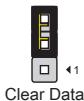
IMPORTANT
You can clear CMOS by shorting 2-3 pin while the system is off. Then return to 1-2 pin position. Avoid clearing the CMOS while the system is on; it will damage the mainboard.
Overclock FSB Switch: OC_SW1 (optional)
You can overclock the FSB to increase the processor frequency by changing the switch. Follow the instructions below to set the FSB.

Default

Increase 10% speed of FSB

Increase 15% speed of FSB

Increase 20% speed of FSB
IMPORTANT
- Make sure that you power off the system before setting the switch.
- When overclocking cause system instability or crash during boot. Please set the switch to default setting.
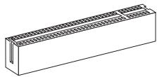
PCI Express Slot
The PCI Express slot supports the PCI Express interface expansion card.
The PCI Express 1.0 x16 slot
The PCI Express 1.0 x1 slot
PCI Slot
The PCI slot supports LAN card, SCSI card, USB card, and other add-on cards that comply with PCI specifications.
IMPORTANT
Make sure that you unplug the power supply first. Meanwhile, read the documentation for the expansion card to configure any necessary hardware or software settings for the expansion card, such as jumpers, switches or BIOS configuration.
PCI Interrupt Request Routing
When adding or removing expansion cards, make the IRQ, acronym of interrupt request line and pronounced I-R-Q, are hardware lines over which devices can send interrupt signals to the microprocessor. The PCI IRQ pins are typically connected to the PCI bus pins as follows:
| Order Slot | 1 | 2 | 3 | 4 |
| PCI 1 | C# | D# | A# | B# |
| PCI 2 | B# | C# | D# | A# |
BIOS SETUP
Power on the computer and the system will start POST (Power On Self Test) process. When the message below appears on the screen, press key to enter Setup.
Press DEL to enter SETUP
If the message disappears before you respond and you still wish to enter Setup, restart the system by turning it OFF and On or pressing the RESET button. You may also restart the system by simultaneously pressing <Ctrl> , <Alt> , and <Delete> keys.
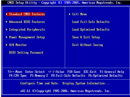
Main Page
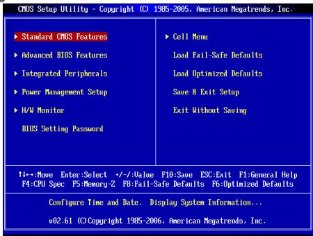
Standard CMOS Features
Use this menu for basic system configurations, such as time, date etc.
Advanced BIOS Features
Use this menu to setup the items of special enhanced features.
Integrated Peripherals
Use this menu to specify your settings for integrated peripherals.
Power Management Setup
Use this menu to specify your settings for power management.
H/W Monitor
This entry shows the status of your CPU, fan, warning for overall system status.
BIOS Setting Password
Use this menu to set BIOS setting Password.
Cell Menu
Use this menu to specify your settings for frequency/voltage control.
Load Fail-Safe Defaults
Use this menu to load the BIOS default values that are factory settings for system operations.
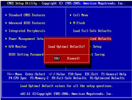
Load Optimized Defaults
Use this menu to load factory default settings into the BIOS for stable system performance operations.
Save & Exit Setup
Save changes to CMOS and exit setup.
Exit Without Saving
Abandon all changes and exit setup.
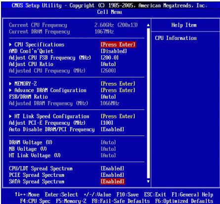
Cell Menu

Current CPU/ DRAM Frequency
It shows the current frequency of CPU/ Memory. Read-only.
CPU Specifications
Press
CPU Technology Support
Press
AMD Cool'n'Quiet
The Cool'n'Quiet technology can effectively and dynamically lower CPU speed and power consumption.
IMPORTANT
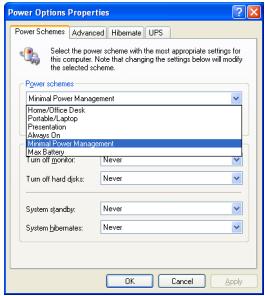
To ensure that Cool'n'Quiet function is activated and will be working properly, it is required to double confirm that:
- Run BIOS Setup, and select Cell Menu. Under Cell Menu, find AMD Cool'n'Quiet, and set this item to "Enabled".
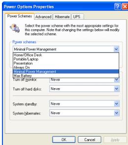
- Enter Windows, and select [Start]->[Settings]->[Control Panel]->[Power Options]. Enter Power Options Properties tag, and select Minimal Power Management under Power schemes.
Adjust CPU FSB Frequency (MHz)
This item allows you to adjust the CPU FSB frequency.
Adjust CPU Ratio
This item is used to adjust CPU clock multiplier (ratio). It is available only when the processor supports this function.
Adjusted CPU Frequency (MHz)
It shows the adjusted CPU frequency (FSB x Ratio). Read-only.
Memory-Z
Press
DIMM1~2 Memory SPD Information
Press
Advance DRAM Configuration
Press
DRAM Timing Mode
This field has the capacity to automatically detect the DRAM timing. If you set this field to [DCT 0], [DCT 1] or [Both], some fields will appear and selectable. DCT 0 controls channel A and DCT1 controls channel B.
1T/2T Memory Timing
When the DRAM Timing Mode is set to [Manual], the field is adjustable. This field controls the command rate. Selecting [1T] makes DRAM signal controller to run at 1 clock cycle rate. Selecting [2T] makes DRAM signal controller run at 2 clock cycles rate.
DCT Unganged Mode
This feature is used to Integrate two 64-bit DCTs into a 128-bit interface.
Bank Interleaving
Bank Interleaving is an important parameter for improving overclocking capability of memory. It allows system to access multiple banks simultaneously.
Power Down Enable
This is a memory power-saving technology. When the system does not access memory over a period of time, it will automatically reduce the memory power supply.
MemClk Tristate C3/ATLVID
This setting allows you to enable/disable the MemClk Tristating during C3 and ATLVID.
FSB/DRAM Ratio
This item will allow you to adjust the ratio of FSB to memory.
Adjusted DRAM Frequency (MHz)
It shows the adjusted memory frequency. Read-only.
HT Link Speed Configuration
Press
HT Link Speed Auto
Setting to [Enabled], the system will detect the HT link speed automatically.
HT Link Speed
This item allows you to set the Hyper-Transport Link speed.
Adjust PCI-E Frequency (MHz)
This item allows you to adjust the PCI-E frequency.
Auto Disable DRAM/PCI Frequency
When set to [Enabled], the system will remove (turn off) clocks from empty DIMM and PCI slots to minimize the electromagnetic interference (EMI).
DRAM Voltage (V)/ NB Voltage (V)/ HT Link Voltage (V)
These items are used to adjust the voltage of CPU, Memory and chipset.
CPU/LDT Spread Spectrum
This setting is used to enable or disable the CPU/LDT (HT Bus multiplier) Spread Spectrum feature.
PCIE Spread Spectrum
This setting is used to enable or disable the PCIE Spread Spectrum feature.
SATA Spread Spectrum
This setting is used to enable or disable the SATA Spread Spectrum feature.
IMPORTANT
- If you do not have any EMI problem, leave the setting at [Disabled] for optimal system stability and performance. But if you are plagued by EMI, select the value of Spread Spectrum for EMI reduction.
- The greater the Spread Spectrum value is, the greater the EMI is reduced, and the system will become less stable. For the most suitable Spread Spectrum value, please consult your local EMI regulation.
- Remember to disable Spread Spectrum if you are overclocking because even a slight jitter can introduce a temporary boost in clock speed which may just cause your overclocked processor to lock up.
Load Optimized Defaults
You can load the default values provided by the mainboard manufacturer for the stable performance.
中国
#
GF615M-P333/P31 SNIKZ (MS-7597 v1.x) Micro-ATX MfInBrdm 1000000000000000000000000000000000000000000000000000000000000000000000000000000000000000000000
Reioh
#
J
- AM3 끝지의 AMD® Phenom™ II X3/ X4 키 Athlon™ X2/ X3/ X4 키로터서 (CPU.org) entire exploit should be found http://www.msi.com/index.php?func=cpuform2 checkpoint
HyperTransport
HyperTransport 1.0
#
NVIDIA® GeForce 6150SE & nForce 430 击伐
J
DDR3800/1066/1333SDRAM(激活时置8GB)
2 DDR3 DIMMs (240 1/5V)
(荷兰:龍達海普服务网)
LAN
Realtek® RTL8111DL®の用10/100/1000 LAN対照(GF615M-P33)
Realtek® RTL8103EL® 10/100 LAN 软件 (GF615M-P31)
0
ATX24FJFJFJFJFJFJFJFJFJFJFJFJFJFJFJFJFJFJFJFJFJFJFJFJFJFJFJFJFJFJFJFJFJFJFJFJFJFJFJFJFJFJFJFJ
- 我們的「連同」詞詞號別為「羅馬達」ATX「連同」詞詞號別為「羅馬達」。
*SisTbAeEaH350WtEoEaH'0iEaH'0iEaH'0iEaH'0iEaH'0iEaH'0iEaH'0iEaH'0iEaH'0iEaH'0iEaH'0iEaH'0iEaH'0iEaH'0iEaH'0iEaH'0iEaH'0iEaH
普罗托迪斯克卡特列FDD1
Current CPU/ DRAM Frequency (端到CPU/DRAM 即合)
CPU Specifications (CPU Specification)
CPU Technology Support (CPU功能支持)
Adjust CPU FSB Frequency (CPU FSB 썸과수 죽지) (MHz)
Adjust CPU Ratio (CPU bit to 0)
Adjusted CPU Frequency (主锁则CPU主卡数) (MHz)
i
Memory-Z (AnMoRi-Z)
DIMM1~2 Memory SPD Information (DIMM1~2 返回 SPD 预览)
Advance DRAM Configuration (GoQ DRAM Nx)
Bank Interleaving (萌克入侵)
Press DEL to enter SETUP
Advanced BIOS Features
Integrated Peripherals
BIOS Setting Password
Current CPU/ DRAM Frequency
CPU Technology Support
Adjust CPU FSB Frequency (MHz)
Adjusted CPU Frequency (MHz)
Adjusted DRAM Frequency (MHz)
Adjust PCI-E Frequency (MHz)
CPU/LDT Spread Spectrum
Press DEL to enter SETUP
Advanced BIOS Features
Integrated Peripherals
BIOS Setting Password
Current CPU/ DRAM Frequency
CPU Technology Support
Adjust CPU FSB Frequency (MHz)
Adjusted CPU Frequency (MHz)
Adjusted DRAM Frequency (MHz)
Adjust PCI-E Frequency (MHz)
CPU/LDT Spread Spectrum
KOMHOENTbI CNCTEMHOI NaTbI
XAPAKTEPNUCTIKN
Пюцeccор
PioeessopbI AMD Phenol II / Althon II / Sempron B KOHcTpyKtBe AM3. (IJIa IONyEnHcAMoHOBn HNfoPmaQmO o CPU, nocTeHTe caIT http://www.msi.com/index.php?func=cpuform2)
HyperTransport
HyperTransport 1.0
Unncet
NVIDIA® GeForce 6150SE & nForce 430
PamrTb
DDR3 800/1066/1333SDRAM(Max.8GB)
3a cnota DDR3 DIMM (240kOH7 1.5V)
(3a dononHnTeBno INHΦoPmaUeN o nopeRkXbAeMbX MOyIpy NocTeTneCai http://www.msi.com/index.php?func=testreport)
LAN
Плобдөрхка 10/100/1000 LAN на чincete Realtek® RTL8111DL (GF615M-P33)
■Иип подөрхька 10/100 LAN на чинсerte Realtek® RTL8103 (GF615M-P31)
Aydno
INTerpnpoBaHHbYuNCeT Realtek ALC888S/ALC889
Aydno 7.1 c rnbkm npeha3naeHne pa3bemOB
CoBmecTnMoCTb co cneunfkaunei Azalia 1.0
IDE
1 nopT IDE
Подэржka рекимов pa60ы Ultra DMA 66/100/133, PIO& Bus Master
SATA
4 nopTa SATA 3Gb/s noDpeKmbaOT 4 npBIOOB SATA 3Gb/s
RAID
SATA1\~4 noDnepKnBaIoT peKmbl RAID 0/1/5/10
Φnonnn
1ФJIOONnnoT
Подержka 1 FDD c 360Kb, 720Kb, 1.2Mb, 1.44Mb u 2.88Mb
KoHHeKTopbl
3aDne nanei
-1PS/2npTMbIu
-1PS/2npTknabnAtypb
- 1 nopT COM
- 1 nopT VGA
- 1 napannelbHbI nopT noDepxNBAeT pexmbl SPP/EPP/ECP
- 1 pa3beM LAN
- 4 nopTa USB 2.0
-63ByKOBbIX pa3beMOB Cn6kIM npeHa3NaeHHeM
Pa3bembl,yctahOBnEHhIeHa nNaTe
- 2 pa3bema USB 2.0
- 1 pa3bem SPDIF-Out
- 1 pa3bem dny nodknoye na yndno ha nepehdne nahe
- 1 pa3bem CD-In
-1pa3bemTPM(onuohalbHO) - 1 pa3bem DaTcNka OTKpbBaHnna Kopnyca
- 1 nepeknquateiannapathoro pa3roha FSB (onuohalbho)
CnotbI
1cnotPCIExpress 1.0× 16
1cnotPCIExpress1.0x1
2 cnoTa PCI, noDnepKka INItepeca PCI uHbIC nTahHeM 3.3V/5V
ΦopM ΦakTop
Micro-ATX (24.4cm X 20.0 cm)
KpereHne
6 OTBepctn DnKpeHneHn
EcnI BAM Heo6xoIMIO pRIO6bCTN AKeCCCyapB IININ y3HATb apTIKyI Bauero IN3dien, 3Ty INHOpMaUIO MOXHO NAIIN B INTEpHET Ha Be6 caJIeNo aDpecy http://www.msi.com/index.php
3ADHЯ PAHEJIb
3aHnaH naHbI npedocabnre cneyuOuNcpepaBembl:
YCTAHOBKA OBOPUIOBAHIN
3Ta rnaBa nocBraIeHa BnOpocAM yCTaHOBKn Ipoceccopa, MoDyIe NamaTn, n nnat paacIneRnA, TAKKe yCTaHOBKe nepeMbueK HcNCTEMNoIaTe. B rnaBe TaKKe pacCKa3bIbAeTcO ToM, KAp NOkDIOuOaTb BHeUHNe YcTpOcTBA, TAKKe KaM bIbS, KNaBnATpy, u.T.D. PnIy TAYoBcK O6OpYDoBAnH 6yDbTe BHNMaTeIbHbI, cNeDuYe Yka3aHnM no YcTAHOBKe.
YctaHOBka npoecccopa n BeHTnIyTopa dIg AM3
Bo n36eJahnne nepepeba npn pa6ote 08aataenHb yctAHOBInBe BHTINIATOp npOecoppa. OndOBpemEHNO, YTObbl yBEniunHb TennopaccenBaHme, y6dntecb B TOM, Yo NaHecen CnTo TnIOnnpoBODJaSeN NaTb Ha npOeccope npn yCTAHOBKe BEHTNIATOpA.
CnedyTe daHbmy kya3aHnM dny npabInbHO uCTahOBKn. HenpabInbna yctahOBka npBBeD T NOBpeXdHIO pOucecoppa n CnCTeMHNO pNaTbl.
1.ПдниммerteВергкалhoeпоножиме рьнхоч,在纳亚姆斯C60kypa38ema。
2. 06pntte BnImaHne Ha 3oToTu cTpeNky (gold arrow)Ha CPU.OHa DOnJXHa 6bItb paCNoJoxHe TaK, KaK nokazao HApncyHke.CPU MOKHO BCTaBt ToIbKO npn erO npabInbHOBOpNEHTaUIN.
3. Pn npabInbHNOyCTAHOBKe CPU ero KOntakTbI NOHNHO BOyUTBpa3BeM, IN HE 6yDet BVIOHO. NOMHHTe, YTOIObIE pnpmeHENHe CINblPn yCtAHOBKe CPU MOKET BbIBaTBc cepE3HbE NobpeXdHnA CICTeMHNOIaTbI.
4.Akkyapatrno pnpxMMTE CPKpa3bemyu andyctne TpHaxok. Pocokby CPU npn onyckanHHpuhXkA moKET nepeMeCTTbC, octopOKHO npxKMITE CPN pIbIaMn BcHTpe TaK, tO6bIOn npabInbHo n oIIOHcTbO 3aФHKcPobBaON Cba3beE.
5. Pâzměctnéte Běvěnátropán Há yzéne kpenětnéhy. Bhučáne zážeřnéte odní ero kpnj.
6. 3aTeM HaxkMTe Ha dpyroI kpaI, Tc0bIy yctahOBnTb padmToH paY3en KpennEnHa. HauHtBe lyhar fikncsui n noDhIMntEero.
7. 3aФИнсчургte padinatop dalbneHIMNOBOPOTCMbpyarA.

- IopKIOHcTe Ka6eBbENTINaTOpa Cpu K COOTBeCTByIOUcEMy pa3bEmy CNCTEMMOI nptbI.
BHIMAHVE
* OToIpaPmN CnCTeMHo NnA tB B 3OM paZdene npBedeHb TOnIbKO nIa demOHcTpaun yCTAHOBM BeHTINrTaTOPa IJn pOuEccopa nod Socket AM3 CPU.BHeuHNI BnBauei Moedn MoKeT OTnWuTaBCr ot npBedeHHoro 3decb.
* PnI OTOCoEINHEnH P#KcNpyUoJero PbHuRa HeO6xOdImo Co6HIOaTb OCTopOxHocB, TAN KAK PbUar NpOnpyJmHEn H npri OTnyckaHOn OH BepHTcA C xDCQHoe NOIooKHeHne.
YCTaHOBKa MOyJeI NAMrTn
- Modynl namartn Imeot ToIbKO anHy npoe3B cepaHne. Moynb BoiDcB 1.
- BCTabbTe MoyIb B BEPTnKaIbHOM HapPabIeHm. 3aTem HaxMnte Ha Hero, YTO6bI zOIOueHbI KOtAKbI rIy60KO norp3yInncB B DIMM cnot. 3oNtBe KoHTaBc EBaBnbl, eCIN MOyIb NaMTn npaBilbNo pa3MeueHb B DIMM cnot.
3.Пл actikOBe 3aueJeknHa o6oXn KOHcax pa3bema 3akpoHTcR ABTOMATNHeCKn
BHIMAHHE
- Modynln DDR3 He bAaMOna3MeHReMb c ModynMaMn DDR2, n CTanIapr DDR3 He IMeet o6bpaTHoCobMeCTmocTeN. MoDyIb naPmT DDR3 cneJeyET yctahabNtBATb Tolsko B paaBem DDR3.
*IpaBostbB DByxKaHaHbHom pexIme yBeintecb, YTO B pa3beMaP a3hIx KaHaNoB y Bac yCTaHOBneHb MoyIn OOnHO rTnA uOnHaKOB eMKoCTn.
* Yto6bI cnTeMa 3aRpykanaB, BHaayane yctaHOBnTE moynb Ba3bEm DIMM1.
24-KoHTaKTHbI pa3bEm 6Ioka nITahnA ATX: JPWR1
3TOT pa3bEM no3BONJET NOKNIQUATb 24-KoHTaKTHbI b6NOK pNTAHnA ATX K CTNEHMH nIATE. NpeED NOkNDIOUHEm y6eINTEc, YTO BCE wITbIPsKn pa3bEMA OT bNOKA pNTAHNPOBbIe, IN OH npABINbHO copneHTnpOBaH. IINTHO BCTAbTe erO aPa3bEM Ha cNCTEMHnPnATE.
ATX 4-KoHTaKThbI pa3bem 6Joka nItaHn: JPWR2
3T0t pa3bEm nitaHn 12B mCnoIb3yeTc Dn o6eCneHn nItaHn npocecoppa.
BHIMAHHE
- Ybεdntεcb, ζτο BCE KOHHeKTOpbl έπιθηλΑXT πραβυMbno ΠοδκηύηeNb.
HactoerhboKeponohyTeCnONb3OaBt6bnoknHTAHN350BT(nBbIe) DnEcheHHeCTabINbHOHTCNCTbEm.
Pa3bEm FDD:FDD1
3TQTpaBempoIeepxHbAeFToONnniDnCKNEmKocTbO 360KB,720KB,1.2MB, 1.44MBn 2.88MB.
PazbEM IDE:IDE1
Pazbem nopepkjBaAeT noeknlochHne XeCTKHX DnCKOB IDE, ONtUHecknx DnCKOB nDpyrIX IDE yctpOCTB.

BHIMAHHE
Pnno ndknoe Hdyx yctpoiBt ha odHom kabe, cnedyet yctahOBntb yctpoIb a pekim master / slave nocpeCTbOM yctahOBKn pepeMbYek. 3a nHTcPTbXaMm OBpaTHeB KdoKemteAun mIRTOBHTen yCTpOCTBa.
Pa3bem Serial ATA: SATA1 ~ 4
Pa3bEm Serial ATA - 30 ByCOKOCOPOCTHOIN NOT HENTPcFepCa Serial ATA. 3OT pa3bEm p03BONJET NOKNIQHTB ToNko ODO yctPOIcTBo Serial ATA.
BHIMAHHE
IVsEgeraTe pe3kIX mIri6OB Ka6eRa Serial ATA. B npotBnHOM cnuyae MOryT BOBHKNHTb notepn dAnhix npi nepeDaue.
PazbemblntaHnBentnIyTopo:CPUFAN, SYSFAN1
PazbEmbl NtnaHBeHTNlTOpOB NOdEperKXBIAoBt BEHTNlTOpBcI NtNaHEM +12 B.PnNOdkIIOUeHN He06xOJIMO nOMNHb,TO Kpckbn NpOboD NOdkIIOuAeTcR K UINHe +12 A, a CepbH - K 3emNe GND. ccnC nCtEhemh NaIATA cOePKHIT MInKPOCXemy Annapathoro MOHOTOPINHa, He06xOJIMo IcNpOlb3OBaBt CneuaNbHbIe BeHTNlTOpBcI DaTChkOM CKOPOCTn DnpeaJIa3aMn FyHKuyn ynpAbeHNBeHTNlTOpOM.

Pa3bem S/PDIF-Out:JSP1
3ToT pAsbem nCOnIb3yETc4 dIe npOKnIOHEnH NHTeppeca S/PDIF (Sony & Philips Digital Interconnect Format) dIe nepeauch 3Byka B UΦpOBOM φopMaTe.
Pa3bEm CD-In: JCD1
3T0t p3abem npedna3nauhen nnoNDkIOUeHHI DOnOINHTbHOro aydno Ka6Ebn.
Pa3bEmblnnoKluOeHnnepeDHe naneHJFP1,JFP2
3TN pa3bEmbl o6ceNcHBAOT nOdknOueHne KHOON k INdMkatopoB nepeDnei naHEn. JFP1 cooTBeTCTByeT cneuФнkaunl Intel® Front Panel I/O Connectivity Design Guide.
Aydno pa3bem nepedne nahan:JAUD1
Pazbem no20bnet no2knohny aaynna ha nependne nanei. OH COOTBETCTBYET cneseiKuaini Intell Front Panel I/O Connectivity Design Guide.
Pazbem USB nepedne naneJUSB1/JUSB2
Pa3bem, KOtOpBIO COBMeTmCO cneuΦnKauaeH IntelI/O Connectivity Design Guide, uaeJeH NpOKnIOHeHry TAKHX BILcOKoKoPocThbIX nepiFepNIbHx yctpoCTB KAK USB HDD, uNΦpaBbIX KaMep, MP3 pIeepOB, npHTepeB, moDEM n T.D.
Pa3bEM TPM MoyJn: JTPM1 (onuohalbHo)
3T0T pa3bEm ppeHa3aHueN dno nnKIOUeHNTPM (Trusted Platform Module) MOyIy. 3a DoONHTeBHOIN HFOpMaueMe IN BO3MOXHOCTMn IcNOIb3OBAHry o6aPITTeB K yPKOBoCTBy nIATpOFmBy Be3onAChOCTn TPM.

Pa3bem DaTUnKa OTKpbIbAHnK Kopnyca: JCI1
K TOMY KONHEKTOPY NOKNIOVAeTc Ka6bEn DaTnHa KOTpbBAnHn KOPnyCa, yctAHOBENHH B KOpNy. Ppi ONtKpBbAHm KOpnyCa erO mExAH3M AKTN3NpyETc.CsTeMa 3aONMOHnAeT OTo Co6bItne H BiDaet npdynpexJdeHne Ha 3kaPme.PpeDynpexJdeHne MoKHO OTKnIOHHTB N HactpoiKaXBIOS.
INHdkaTOP COCTOHNAPS:LED1 (onuohalho)
3TNHnDnKatopb APS (Active Phase Switching) LED nok3aIbaIOT peXIM pa60tBuNCTOHNKa nTAnHn pnoecoppa. NHΦOpMaunO o cOToHN HnDnKaTopoB npBeDeHa bTaBnIe.


Ckopocb FSB noBbIaetcH a15%

Ckopocb FSB noBbIaetcH na 20%
BHIMAHHE
- Pēneρ περετάθουκόν περεκλίουσατέληγύδειπεςθυ ΜΤΟ, ΚΤΟ ΚΗΓΕΜΑ BbΚΙΝΥΗς.
Ecnn annapathbni pa3roH BbI3bIaET HeCTaBnIbHOCTb IIN ABAPNIHyo XtAHOBKY CNTeMbI npri 3arpy3ke, yctahOBITE nepeKInOAteINB 3haueHne no yomJIuHNo.
Cnot PCI Express
Cnot PCIE noDpeKnaeT KapbI paacunpeHn Hntepceca PCI Express.
PCI Express 1.0 x16 cnot
PCI Express 1.0 x1 cnot
Cnot PCI
Cnot PCI no30baonetay ctaHOBInb Kaptb LAN, SCSI, USB n npyrme doonHnTeBhBie Kaptb paacupeHnKOTOpbIe COoTBETCTBYIOT cneuNkaumPCI.
BHIMAHHE
Y6eintecb, yto Kaebnb nntanm OTKnOcven OT 3neKtpnuecko CETn. PpOHTNE dOKyMENTAUNH aKAPT pAcuPnEHN N BbIOnNHTe Heo6xoDnMbte annpaTHbe nn npOrpAMhbYe UCTAHOBKn DAnDAHNOIN PaTbI, TaKHe KAK nepeMbUKN, nepeKNoUoateInnn KOnHOFpyauNIOBIS.
MapuTn3aun 3anpocob npepbBaHnPCI
Pn yctaHOBke nIN OTKIOUeHn KAPt pacIupeHn y6eIntEcB, YTO IRQ - cokpaueHne ot interrupt request (line) - nINHn 3anpoca npebIBaHn, annapatna HnINHn, no KOTopoI yCTpoCTBa MOryT noCbIaNb TcHnA npepbIBaHn MIKponpoUeCCopy. ObIyHoe NoKIOUeHne PCI IRQ K KOHTaKTam IInhBi PCI nokaHO NIXe:
| Order Slot | 1 | 2 | 3 | 4 |
| PCI 1 | C# | D# | A# | B# |
| PCI 2 | B# | C# | D# | A# |
HACTPOIMKA BIOS
BKnUHTe NITAHNE KOMbIbTePAp. Ipn 3tOM 3anyCTnCPOueDpya POST (Tect BKNIOHEnI NITAHN). Korda Na 3kpeA NOBcTcP npiBeDeHNO HnKe COo6HeJIe, HAKMITE KANbIuSy < DEL> Inra BxOda B pEKm HAcTPOKn.
Main Page (OchOBHoe MeHIO)
Standard CMOS Features (CTaHdapTHbIe yHKm CMOS)
3TO MEO HIO 0BONJET YCTAHOBINT BCHOBHIE NAPAMETbI KOHNIGYPAaUNI CHTEMbl (DAyT, BPMAE, n T..d.)
Advanced BIOS Features (Доюнтьньгд Функш BIOS)
3To MeHIO nCnOJIb3yETcI dIa HAcTpoKn CneUaJIbHbIX fHyKcIINBIOS.
Integrated Peripherals (BCTpoehhble nepupepnhbye yctpoicta)
3TOmEHNOIbEyETcJnAHaTcPOIKnMapaMeTPOB BCTPOEHNbX npHnFepRnBHXyctPObCTB.
Power Management Setup (Hactpoika ynpablenia nitaHnem)
3TO MEHIO N03BOJAreT 3aDaTb npaMeTpbl ynpaBneHnI NITAHmE CNTeMbI.
H/W Monitor (MoHTop annapaTHou actn)
3TOT nyHKT OTO6pKaet COCTOHNe annapathOH Yactn PIK.
BIOS Setting Password (Паров дocун К hashpoikam BIOS)
3TO MEHIO NcNOJIb3yETcra, YTO6bl 3aadTb napOJIb.
Cell Menu (Mehio nra pa3roha)
3TO MEHIO NOBBOJET YNPABTb TAKTOBIMu cAChTOTAMn HANPRAKENAMM pN P aRHOte CHTeMb.
Load Fail-Safe Defaults
3To MEOHIO NCON5yETaI IN 3aqrpy3kn 3haeHNbBIOS,yCTaHOBENbIX npno3AHTIeTEnM IIN TcAStInbHbN paBOtI cnCTeMbI.
Load Optimized Defaults (YctahOBntb onTImmaIbHbIe HAcTpOki)
3TO MeHIO INCNOLIByETCnI YC TAHOBKM HACTPOEK INAGOBOTBNTELI DNYTOMNHABHO PNOINBDOTENHBOCTN CHTEMHNOI PnATb.
Save & Exit Setup (BbIXoD c coXpaHHeHem HactpoE)
3aIncb n3MeHEni B CMOS n BbIXoD n3 peKIma NaCTpOKn.
Exit Without Saving (BbIXoD 6e3 coxpaHEnn)
OTmeHa BcEx N3MeHeHn N bIXoD n3 pexIMa HAcTpoKN.
Cell Menu
Current CPU/ DRAM Frequency
3TNyHKtblnok3aBbAoiTeKyuIyo YactOTy CPU nCKopoCTb narnToTbKnOkD TyeHnE.
CPU Specifications
JahMkme
CPU Technology Support
Hakmite Enter] nBxOda b NOpdmHeo. B NOpdmHeo noka3aHbIy TeHONJorIn, KOTOpbeN OndepKmbAIOCTc BY tChAOBJIeHN CPM.
AMD Cool'n'Quiet
Texohonorha Cool'Quiet no3boJare 3ΦΦeTKBHO DnHAMMueckn 13MeHertb aactoy CPU n 3heponrtope6neHme CNTeMb.
BHIMAHVE
YtO6bIy 6eJntcB a B TOM, YTO texHONORNA Cool'Jniet BkUoyena n paB0aTe npAribNo, Heo6XoDMIO:
- 3aɪtɪn bɪpɒrρʌmmy BIOS Setup, nɪbɪsɒpər Cell Menu. Hauɪdɪte AMD Cool'n'Quiet noq Cell Menu, yctəhʊbəre ero b'Ena'de'.
- B Windows BBb6epnTe [Start->[Settings]->[Control Panel]->[Power Options].BoiDnTe B Power Options Properties, BBb6epnTe Minimal Power Management B Power schemes.
Adjust CPU FSB Frequency (Mfμ)
3TOT nyHKT no3BONJET Bb6paTb qacToTy FSB npoceccopa.
Adjust CPU Ratio
3TOT nyHKT nCnONbEycTd PeryNtPOBm MHOXKNTe NpOecccPO. OH DOctyHnToIbKO TOra, KOra nPoecocc NoedePKBaAET 3y fYHKNUO.
Adjusted CPU Frequency (Mμ)
3TOT nyHKT noka3bIbaET Tekyuyu yactoty CPU (FSB x Ratio).ToIbko dIy TcTeHnA.
Memory-Z
Haxmnte
DIMM1~2 Memory SPD Information
Haxmite
Advance DRAM Configuration
Haxmnte
DRAM Timing Mode
3TOT nyHKT no3B0BJeT ABOMATMueckn onpeIeIb Tbc BpeMeHNbIe napametbI yDRAM. Ipi ycTaHOBBe 3aueHenri [DCT 0], [DCT 1] iIN [Both], HekOTOpBy PnyKtBi NOBIAHOTcN a CTAHy DoCTyHbI. DCT 0 KOHTpONIpYeT Kahan A n DCT1 KOHTpONIpYeT Kahan B.
1T/2T Memory Timing
Pn yctahOBke DRAM Mode B [Manual], 3T0 TnyHK CTaHOBtca DoCTyNHbM. 3T0 TnyHK ONpeDeneT KcOPOCT bByIaHcKOMaHd SDRAM. Bby6op [1T] nepeBodT cHrHaNb hKOTpONeP SDRAM B pexm pa60tBu (T=KaTt REhepatOp). Bby6op [2T] BKnIuOaET cHrHaNb hKOTpONeP SDRAM B pexm pa60tBu cKoPCoTbU 2T.
DCT Unganged Mode
3TOTnyHKHCN0B3yETc4Ia6bEaHINeHnA DByx 64-6HTbIX DCT B OAn12 8-6HTNb HmTERPeFbc.
Bank Interleaving
Bank Interleaving JIJIETcB BAXHIM napametpOM, BINHOUMM HApON3BOJNTeJIbOCT naTmI. Ero BKOJUeHne no3BOJaTeT o6paatbcK HECKOLKM 6BANKAM nAMRTN ODHOBEMEHNO.
Power Down Enable
3TOT nyHK T KOHPTONIPYET PABOTY TEXHOORM N 3HEPROC6epeXeHHa. PnO tCYCTBm BOpaeeHN K NaMHTN B TeueHNE HeKOTOPORo BpEmEH, CNTcTeMa bAOTMACTeCKN yMeHbSAaETIANTAHNE IINr NaMHTN.
MemClk Tristate C3/ATLVID
3TOT NYHK TNOBIONET BIKHOATb/BbIKHOATb PEXKIM pa60tby c TPMER COCTHONYM BO BYPEM C3 uATLVID.
FSB/DRAM Ratio
3TOT nyHKT no3BONJET perynnpoBaTB qactOy FSB n DRAM.
Adjusted DRAM Frequency (Mf)
3TOT nyHKT noka3bIbaET kkyuO yactOtynamrT.Nolko dnyTeHnA.
HT Link Speed Configuration
Haxmte
HT Link Speed Auto
Pyr yctahOBBe B [Enabled], cHCTeMa aBToMaTHuCheKn OnpedEnaTe KcOpOCTb 1nHHI HT.
HT Link Speed
3TOT nyHKT no3B0BraRt yCTaHOBnBt cKOpOCTb nepeDaun no shne HyperTransport.
Adjust PCI-E Frequency (MΓu)
ETOTnyHKNTN03BONReTycTaHOBnTByactOTyPCIE.
Auto Disable DRAM/PCI Frequency
Pn yctahOBke 3naueHIna [Enabled], CnCTeMa OTKnOHT HeICNOnb3yEmbIe pa3BeMbI namrTn IPCI, TTO npBedeT K cnHexeHIO UpoBHr 3NeKtPOMaHrTHbIX nomex (EMI).
DRAM Voltage (V)/ NB Voltage (V)/ HT Link Voltage (V)
TOT nyHKT no3Bolaret perynpobatb hnapxkeHne CPU, namrtn uynnceta.
CPU/LDT Spread Spectrum
3T0T pyNKT hcnONbEyetc TnB KlnOHeHy/ BkInKHeHy TeXHOBrOg CPU/LDT (HT Bus multiplier) Spread Spectrum.
PCIE Spread Spectrum
3TOT NyHK TcNbONbEyTCa DnB BKNoHcHb/ BbKIOHcHbTexHONOrn PCIE Spread Spectrum.
SATA Spread Spectrum
3TOT YNHKT NCOINB3yETcA DnA BKNIOChENr/ BbKIOChENr TexHONrN SATA Spread Spectrum.
BHIMAHHE
- Ecni y BAC het npobnem c nomexamn, octabte 3nauehne [Disabled] (stanpeuho) dnyuwei ctabunbHOCTN i npou3BODIHTNBHOCTN. Ondako, ecni y BAC BOHNIKAIO TNEKTPOMARHNbIbe NOMEXN, Bblbepnte Spread Spec-trum dnia uxymehbEHHa.
* Yem 6oJIbwe 3naueHne Spread Spectrum, Tm Hnke oyDeT yOpeBHe 3eKtPOMaTHNtBx NOMex, Ho CnCTema cTahet Meehe StaBnHbON. IyBa IbObe npXoJMyE O3naueHne Spred SpareSpcDc BcpeTecb co 3naueHernMn yOpeBHe 3eKtPOMaTHNtBx NOMex, yctAHOBnEHhX 3AKOHDaTeNbCTBOM. - He 3a6yblte 3a9pntHb IcnoIb3ObaHne FyHKcMn Spread Spectrum, ecn bbl «pa3roHaHTe» CNTeMHy IO nATy. 3To Heo6xOJIMo, TAK KAK daXe HeoNlsWIO dpe6e3r CRIHANOB TAKTOBORO reHEPATOPa MOKeT npINBecTN K OTKa3y «pa3orHaHHOrO» IpoUeCCoppa.
YctaHObKa 3HaueHn no yMOnJauHnIO
Ia 3abHbno a60b tbc CTcEmbl Bbl Mokete 3ary3ntb 3haeHBIOS, yctahOBHeHbe pno3BdoHTenem CtchEMnPiTaB.

简体中文
简介
Press DEL to enter SETUP
(按DEL键进入设定)
CPU Specifications (CPU 属性)
CPU/LDT Spread Spectrum (CPU/LDT 频展)
硬體超頻FSB開關:OC_SW1(選配)
Press DEL to enter SETUP
(按DEL键進入設定)
Integrated Peripherals (整合型週邊)
使用本選單設定整合型週邊裝置。
Adjust CPU FSB Frequency (MHz) (调整CPUFSB频率)
Adjusted CPU Frequency (MHz) (調整後CPU頻率)
Press DEL to enter SETUP
(千米一押七设定画面呼出)
CMOS Setup Utility - Copyright (C) 1985-2005, American Negatrends, Inc.
Standard CHOS Features
Advanced BIOS Features
Integrated Peripherals
Power Management Setup
H/V Monitor
BIOS Setting Password
Cell Menu
Load Fail-Safe Defaults
Load Optimized Defaults
Save 8 Exit Setup
Exit Without Saving
Move Enter:Select +/-Value F10:Save ESC:Exit F1:General Help
F4:CPU Spec F5:Memory-2 F8:Fail-Safe Defaults F6:Optimized Defaults
Configure Time and Date. Display System Information...
002.61 (C) Copyright 1985-2006, American Megatrends, Inc.
CPU Technology Support(CPUtekNoJ-safo-1)
CPU/LDT Spread Spectrum
CPU/LDT (HT Bus multiplier) Spread Spectrum特性を有効/無効にしま�。
PCIE Spread Spectrum