
GF615M-P31 - Electronic component MSI - Free user manual and instructions
Find the device manual for free GF615M-P31 MSI in PDF.

| Product type | Micro-ATX Motherboard |
| Brand | MSI |
| Model | GF615M-P31 |
| Chipset | NVIDIA GeForce 6150SE & nForce 430 |
| Processor socket | AM3 |
| Supported processors | AMD Phenom II / Athlon II / Sempron |
| Supported memory | DDR3 800/1066/1333, up to 8 GB (2 x DIMM) |
| Storage | 1 IDE port (Ultra DMA 66/100/133), 4 SATA 3 Gb/s ports (RAID 0/1/5/10) |
| Integrated audio | Realtek ALC888S/ALC889, 7.1 channels, HD Audio |
| Network | Realtek RTL8103EL, 10/100 LAN |
| Rear panel connectors | 1 PS/2 mouse, 1 PS/2 keyboard, 1 COM, 1 VGA, 1 parallel, 1 RJ45, 4 USB 2.0, 6 audio jacks |
| Internal connectors | 2 USB 2.0, SPDIF-Out, front audio, CD-In, TPM, Chassis Intrusion, FSB overclock switch |
| Expansion slots | 1 PCIe x16, 1 PCIe x1, 2 PCI |
| Dimensions | 24.4 cm x 20.0 cm |
| Form factor | Micro-ATX |
| Required power supply | ATX 24-pin + 4-pin, recommended 350 W or more |
| Main features | Support Cool'n'Quiet, overclocking via FSB switch, power management, configurable BIOS |
| Maintenance and cleaning | Regular dusting with compressed air, avoid moisture, do not touch bare components |
| Safety | Discharge static electricity before handling, do not plug in while powered |
| Spare parts and repairability | Standard components (CPU, RAM, etc.) replaceable; repair by qualified technician recommended |
| General information | Reliable motherboard for desktop PC, compatible with Windows and Linux |
Frequently Asked Questions - GF615M-P31 MSI
User questions about GF615M-P31 MSI
0 question about this device. Answer the ones you know or ask your own.
Ask a new question about this device
Download the instructions for your Electronic component in PDF format for free! Find your manual GF615M-P31 - MSI and take your electronic device back in hand. On this page are published all the documents necessary for the use of your device. GF615M-P31 by MSI.
USER MANUAL GF615M-P31 MSI
FCC-B RADIO FREQUENCY INTERFERENCE STATEMENT
This equipment has been tested and found to comply with the limits for a class B digital device, pursuant to part 15 of the FCC rules. These limits are designed
to provide reasonable protection against harmful interference in a residential installation. This equipment generates, uses and can


N1996
radiate radio frequency energy and, if not installed and used in accordance with the instruction manual, may cause harmful interference to radio communications. However, there is no guarantee that interference will occur in a particular installation. If this equipment does cause harmful interference to radio or television reception, which can be determined by turning the equipment off and on, the user is encouraged to try to correct the interference by one or more of the measures listed below.
Reorient or relocate the receiving antenna.
Increase the separation between the equipment and receiver.
Connect the equipment into an outlet on a circuit different from that to which the receiver is connected.
Consult the dealer or an experienced radio/ television technician for help.
Notice 1
The changes or modifications not expressly approved by the party responsible for compliance could void the user's authority to operate the equipment.
Notice 2
Shielded interface cables and A.C. power cord, if any, must be used in order to comply with the emission limits.
VOIR LA NOTICE D'INSTALLATION AVANT DE RACCORDER AU RESEAU.

Micro-Star International MS-7597
This device complies with Part 15 of the FCC Rules. Operation is subject to the following two conditions:
(1) this device may not cause harmful interference, and
(2) this device must accept any interference received, including interference that may cause undesired operation.
PART NUMBER
G52-75971X6
COPYRIGHT NOTICE
The material in this document is the intellectual property of MICRO-STAR INTERNATIONAL. We take every care in the preparation of this document, but no guarantee is given as to the correctness of its contents. Our products are under continual improvement and we reserve the right to make changes without notice.
TRADEMARKS
All trademarks are the properties of their respective owners.
MSI is registered trademark of Micro-Star Int'l Co., Ltd.
NVIDIA® is registered trademark of NVIDIA Corporation.
ATI® is registered trademark of ATI Technologies, Inc.
AMD is registered trademarks of AMD Corporation.
Intel is registered trademarks of Intel Corporation.
Windows® is registered trademarks of Microsoft Corporation.
AMI is registered trademark of Advanced Micro Devices, Inc.
Award® is a registered trademark of Phoenix Technologies Ltd.
Sound Blaster® is registered trademark of Creative Technology Ltd.
Realtek® is registered trademark of Realtek Semiconductor Corporation.
■ JMicron® is registered trademark of JMicron Technology Corporation.
Netware is a registered trademark of Novell, Inc.
REVISION HISTORY
| Revision | Revision History | Date |
| V1.2 | Add a new model GF615M-P33 | May 2009 |
| V1.3 | For GF615M-P33/ P31 | December 2009 |
| V1.5 | Update JSP1 from V1.3 | July 2010 |
SAFETY INSTRUCTIONS
Always read the safety instructions carefully.
- Keep this User Manual for future reference.
- Keep this equipment away from humidity.
Lay this equipment on a reliable flat surface before setting it up.
- The openings on the enclosure are for air convection hence protects the equipment from overheating. Do not cover the openings.
- Make sure the voltage of the power source and adjust properly 110/220V before connecting the equipment to the power inlet.
- Place the power cord such a way that people can not step on it. Do not place anything over the power cord.
Always Unplug the Power Cord before inserting any add-on card or module.
All cautions and warnings on the equipment should be noted.
- Never pour any liquid into the opening that could damage or cause electrical shock.
If any of the following situations arises, get the equipment checked by a service personnel:
The power cord or plug is damaged.
Liquid has penetrated into the equipment.
The equipment has been exposed to moisture.
The equipment does not work well or you can not get it work according to User Manual.
The equipment has dropped and damaged.
The equipment has obvious sign of breakage.
- Do not leave this equipment in an environment unconditioned, storage temperature above 60^ (140^) , it may damage the equipment.
CAUTION
Danger of explosion if battery is incorrectly replaced. Replace only with the same or equivalent type recommended by the manufacturer.
警告使用者
For better environmental protection, waste batteries should be collected separately for recycling or special disposal.
ENGLISH
To protect the global environment and as an environmentalist, MSI must remind you that...
Under the European Union ("EU") Directive on Waste Electrical and Electronic Equipment, Directive 2002/96/EC, which takes effect on August 13, 2005, products of "electrical and electronic equipment" cannot be discarded as municipal waste anymore and manufacturers of covered electronic equipment will be obligated to take back

such products at the end of their useful life. MSI will comply with the product take back requirements at the end of life of MSI-branded products that are sold into the EU. You can return these products to local collection points.
DEUTSCH
Thank you for choosing the GF615M-P33/ P31 series (MS-7597 v1.x) Micro-ATX mainboard. The GF615M-P33/ P31 series is design based on NVIDIA® Geforce 6150SE & nForce 430 chipset for optimal system efficiency. Designed to fit the advanced AMD Phenom™ AM3 processor, the GF615M-P33/ P31 series deliver a high performance and professional desktop platform solution.
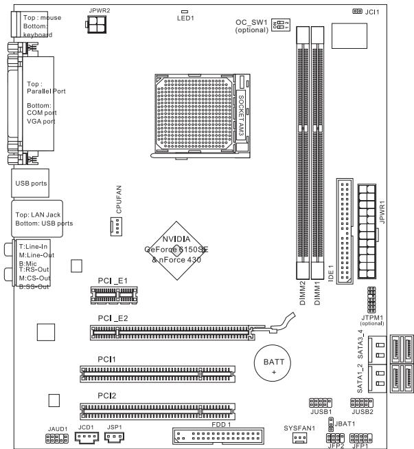
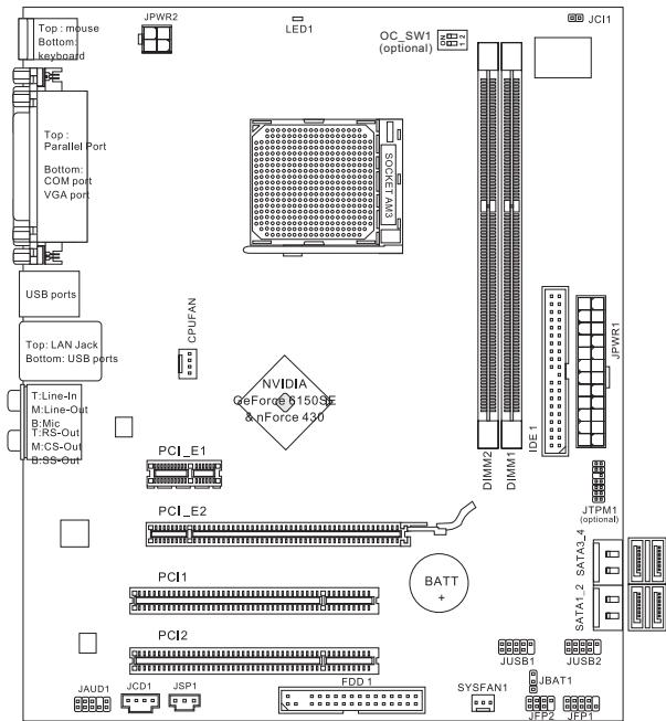
Layout
SPECIFICATIONS
Processor Support
Supports AMD Phenom II / Althon II / Sempron processors in the AM3 package.
(For the latest information about CPU, please visit
http://www.msi.com/index.php?func=cpuform2)
HyperTransport
HyperTransport 1.0
Chipset
NVIDIA® Geforce 6150SE & nForce 430 chipset
Memory Support
DDR3 800/1066/1333SDRAM(totalMax.8GB)
2 DDR3 DIMMs (240pin/ 1.5V)
(For more information on compatible components, please visit http://www.msi.
com/index.php?func=testreport)
LAN
Supports 10/100/1000 LAN by Realtek® RTL8111DL (GF615M-P33)
Or supports 10/100 LAN by Realtek® RTL8103EL (GF615M-P31)
Audio
Chip integrated by Realtek® ALC888S/ ALC889
Supports 7.1 channels audio out
Compliant with Azalia 1.0 Spec
IDE
1 IDE port
Supports Ultra DMA 66/100/133, PIO & Bus Master operation mode
SATA
4 SATA 3Gb/s ports by NVIDIA® nForce 430
RAID
SATA1~4 support RAID 0/1/5/10
Floppy
1 floppy port
Supports 1 FDD with 360 KB, 720 KB, 1.2 MB, 1.44 MB and 2.88 MB
Connectors
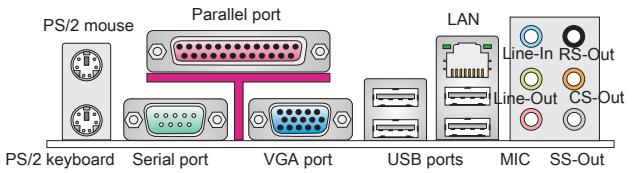
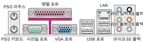
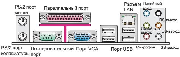
Back panel
-1PS/2 mouse port
- 1 PS/2 keyboard port
- 1 COM port
- 1 VGA port
- 1 parallel port supporting SPP/EPP/ECP mode
- 1 LAN jack
- 4 USB 2.0 Ports
- 6 flexible audio jacks
On-Board Connectors
- 2 USB 2.0 connectors
- 1 SPDIF-Out connector
- 1 Front Panel Audio connector
- 1 CD-In connector
- 1 TPM connector (optional)
- 1 Chassis Intrusion Connector
- 1 Overclock FSB Switch (optional)
Slots
1 PCI Express 1.0 x16 slot
1 PCI Express 1.0 x1 slot
2 PCI slots, support 3.3V/5V PCI bus Interface
Form Factor
Micro-ATX (24.4cm X 20.0 cm)
Mounting
6 mounting holes
If you need to purchase accessories and request the part numbers, you could search the product web page and find details on our web address below http://www.msi.com/index.php
REAR PANEL
The rear panel provides the following connectors:
HARDWARE SETUP
This chapter provides you with the information about hardware setup procedures. While doing the installation, be careful in holding the components and follow the installation procedures. For some components, if you install in the wrong orientation, the components will not work properly. Use a grounded wrist strap before handling computer components. Static electricity may damage the components.
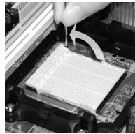
CPU & Cooler Installation for AM3
When you are installing the CPU, make sure the CPU has a cooler attached on the top to prevent overheating. Meanwhile, do not forget to apply some thermal paste on CPU before installing the heat sink/cooler fan for better heat dispersion.
Follow the steps below to install the CPU & cooler correctly. Wrong installation will cause the damage of your CPU & mainboard.
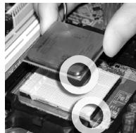
- Pull the lever sideways away from the socket. Make sure to raise the lever up to a 90-degree angle.
- Look for the gold arrow of the CPU. The gold arrow should point as shown in the picture. The CPU can only fit in the correct orientation.
- If the CPU is correctly installed, the pins should be completely embedded into the socket and can not be seen. Please note that any violation of the correct installation procedures may cause permanent damages to your mainboard.
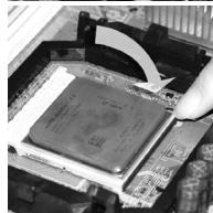
- Press the CPU down firmly into the socket and close the lever. As the CPU is likely to move while the lever is being closed, always close the lever with your fingers pressing tightly on top of the CPU to make sure the CPU is properly and completely embedded into the socket.
- Position the cooling set onto the retention mechanism. Hook one end of the clip to hook first.
- Then press down the other end of the clip to fasten the cooling set on the top of the retention mechanism. Locate the Fix Lever and lift up it.
- Fasten down the lever.
- Attach the CPU Fan cable to the CPU fan connector on the mainboard.

IMPORTANT
- Mainboard photos shown in this section are for demonstration of the cooler installation for Socket AM3 CPUs only. The appearance of your mainboard may vary depending on the model you purchase.
- While disconnecting the Safety Hook from the fixed bolt, it is necessary to keep an eye on your fingers, because once the Safety Hook is disconnected from the fixed bolt, the fixed lever will spring back instantly.
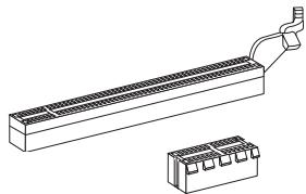
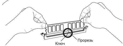
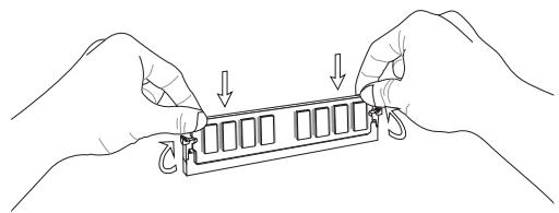
Installing Memory Modules
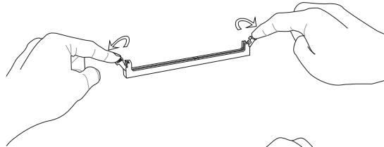
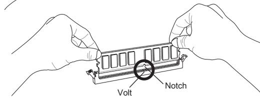
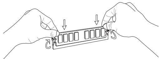
- The memory module has only one notch on the center and will only fit in the right orientation.
- Insert the memory module vertically into the DIMM slot. Then push it in until the golden finger on the memory module is deeply inserted in the DIMM slot. You can barely see the golden finger if the memory module is properly inserted in the DIMM slot.
- The plastic clip at each side of the DIMM slot will automatically close.
IMPORTANT
- DDR3 memory modules are not interchangeable with DDR2 and the DDR3 standard is not backwards compatible. You should always install DDR3 memory modules in the DDR3 DIMM slots.
- In Dual-Channel mode, make sure that you install memory modules of the same type and density in different channel DIMM slots.
- To enable successful system boot-up, always insert the memory modules into the DIMM1 first.
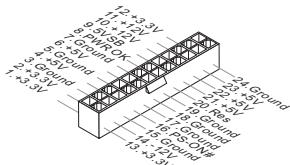
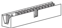
ATX 24-Pin Power Connector: JPWR1
This connector allows you to connect an ATX 24-pin power supply. To connect the ATX 24-pin power supply, make sure the plug of the power supply is inserted in the proper orientation and the pins are aligned. Then push down the power supply firmly into the connector.

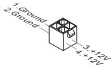
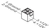
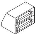
ATX 4-Pin Power Connector: JPWR2
This 12V power connector is used to provide power to the CPU.
IMPORTANT
- Make sure that all the connectors are connected to proper ATX power supplies to ensure stable operation of the mainboard.
- Power supply of 350 watts (and above) is highly recommended for system stability.
Floppy Disk Drive Connector: FDD1
This connector supports 360 KB, 720 KB, 1.2 MB, 1.44 MB or 2.88 MB floppy disk drive.
IDE Connector: IDE1
This connector supports IDE hard disk drives, optical disk drives and other IDE devices.
IMPORTANT
If you install two IDE devices on the same cable, you must configure the drives to cable select mode or separately to master / slave mode by setting jumpers. Refer to IDE device documentation supplied by the vendors for jumper setting instructions.
Serial ATA Connector: SATA1 ~ 4
This connector is a high-speed Serial ATA interface port. Each connector can connect to one Serial ATA device.
IMPORTANT
Please do not fold the Serial ATA cable into 90-degree angle. Otherwise, data loss may occur during transmission.
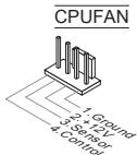
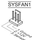
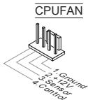
Fan Power Connectors: CPUFAN, SYSFAN1
The fan power connectors support system cooling fan with +12V . When connecting the wire to the connectors, always note that the red wire is the positive and should be connected to the +12V ; the black wire is Ground and should be connected to GND. If the mainboard has a System Hardware Monitor chipset onboard, you must use a specially designed fan with speed sensor to take advantage of the CPU fan control.
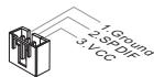
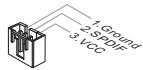
S/PDIF-Out Connector: JSP1
This connector is used to connect S/PDIF (Sony & Philips Digital Interconnect Format) interface for digital audio transmission.
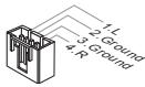
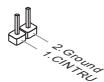
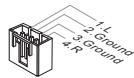
CD-In Connector: JCD1
This connector is provided for external audio input.
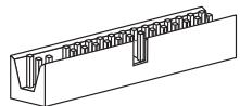
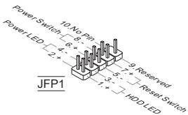
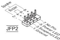
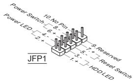
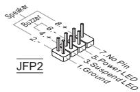
Front Panel Connectors: JFP1, JFP2
These connectors are for electrical connection to the front panel switches and LEDs. The JFP1 is compliant with Intel® Front Panel I/O Connectivity Design Guide.
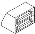
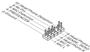
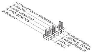
Front Panel Audio Connector: JAUD1
This connector allows you to connect the front panel audio and is compliant with Intel® Front Panel I/O Connectivity Design Guide.
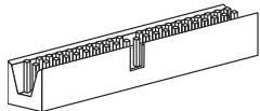
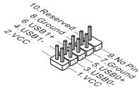
Front USB Connector: JUSB1/ JUSB2
This connector, compliant with Intel® I/O Connectivity Design Guide, is ideal for connecting high-speed USB interface peripherals such as USB HDD, digital cameras, MP3 players, printers, modems and the like.
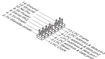
TPM Module connector: JTPM1 (optional)
This connector connects to a TPM (Trusted Platform Module) module. Please refer to the TPM security platform manual for more details and usages.
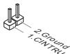
Chassis Intrusion Connector: JCI1
This connector connects to the chassis intrusion switch cable. If the chassis is opened, the chassis intrusion mechanism will be activated. The system will record this status and show a warning message on the screen. To clear the warning, you must enter the BIOS utility and clear the record.
APS LED Status Indicator:LED1
These APS (Active Phase Switching) LED indicates the current CPU power phase mode. Follow the instructions below to read.

| ON | The LED will light when CPU is in 3 phase power mode. |
| OFF | The LED off when CPU is in 1 phase power mode. |
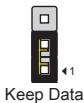
Clear CMOS Jumper: JBAT1
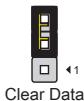
There is a CMOS RAM onboard that has a power supply from an external battery to keep the data of system configuration. With the CMOS RAM, the system can automatically boot OS every time it is turned on. If you want to clear the system configuration, set the jumper to clear data.
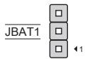
IMPORTANT
You can clear CMOS by shorting 2-3 pin while the system is off. Then return to 1-2 pin position. Avoid clearing the CMOS while the system is on; it will damage the mainboard.
Overclock FSB Switch: OC_SW1 (optional)
You can overclock the FSB to increase the processor frequency by changing the switch. Follow the instructions below to set the FSB.

Default

Increase 10% speed of FSB

Increase 15% speed of FSB

Increase 20% speed of FSB
IMPORTANT
- Make sure that you power off the system before setting the switch.
- When overclocking cause system instability or crash during boot. Please set the switch to default setting.
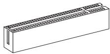
PCI Express Slot
The PCI Express slot supports the PCI Express interface expansion card.
The PCI Express 1.0 x16 slot
The PCI Express 1.0 x1 slot
PCI Slot
The PCI slot supports LAN card, SCSI card, USB card, and other add-on cards that comply with PCI specifications.
IMPORTANT
Make sure that you unplug the power supply first. Meanwhile, read the documentation for the expansion card to configure any necessary hardware or software settings for the expansion card, such as jumpers, switches or BIOS configuration.
PCI Interrupt Request Routing
When adding or removing expansion cards, make the IRQ, acronym of interrupt request line and pronounced I-R-Q, are hardware lines over which devices can send interrupt signals to the microprocessor. The PCI IRQ pins are typically connected to the PCI bus pins as follows:
| Order Slot | 1 | 2 | 3 | 4 |
| PCI 1 | C# | D# | A# | B# |
| PCI 2 | B# | C# | D# | A# |
BIOS SETUP
Power on the computer and the system will start POST (Power On Self Test) process. When the message below appears on the screen, press key to enter Setup.
Press DEL to enter SETUP
If the message disappears before you respond and you still wish to enter Setup, restart the system by turning it OFF and On or pressing the RESET button. You may also restart the system by simultaneously pressing <Ctrl> , <Alt> , and <Delete> keys.
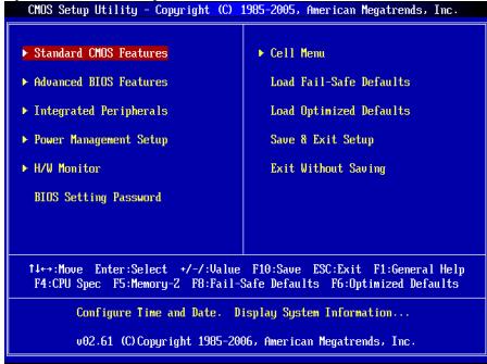
Main Page
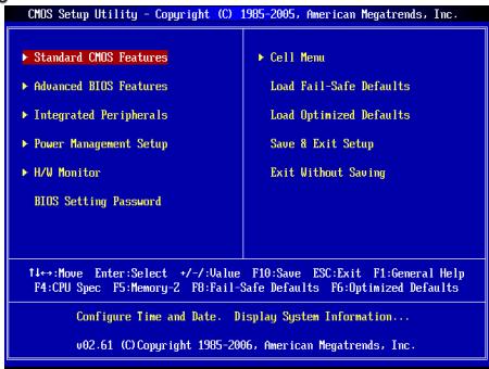
Standard CMOS Features
Use this menu for basic system configurations, such as time, date etc.
Advanced BIOS Features
Use this menu to setup the items of special enhanced features.
Integrated Peripherals
Use this menu to specify your settings for integrated peripherals.
Power Management Setup
Use this menu to specify your settings for power management.
H/W Monitor
This entry shows the status of your CPU, fan, warning for overall system status.
BIOS Setting Password
Use this menu to set BIOS setting Password.
Cell Menu
Use this menu to specify your settings for frequency/voltage control.
Load Fail-Safe Defaults
Use this menu to load the BIOS default values that are factory settings for system operations.
Load Optimized Defaults
Use this menu to load factory default settings into the BIOS for stable system performance operations.
Save & Exit Setup
Save changes to CMOS and exit setup.
Exit Without Saving
Abandon all changes and exit setup.
Cell Menu
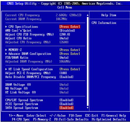
Current CPU/ DRAM Frequency
It shows the current frequency of CPU/ Memory. Read-only.
CPU Specifications
Press
CPU Technology Support
Press
AMD Cool'n'Quiet
The Cool'n'Quiet technology can effectively and dynamically lower CPU speed and power consumption.
IMPORTANT
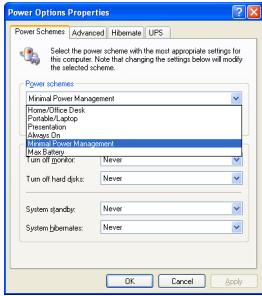
To ensure that Cool'n'Quiet function is activated and will be working properly, it is required to double confirm that:
- Run BIOS Setup, and select Cell Menu. Under Cell Menu, find AMD Cool'n'Quiet, and set this item to "Enabled".
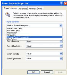
- Enter Windows, and select [Start]->[Settings]->[Control Panel]->[Power Options]. Enter Power Options Properties tag, and select Minimal Power Management under Power schemes.
Adjust CPU FSB Frequency (MHz)
This item allows you to adjust the CPU FSB frequency.
Adjust CPU Ratio
This item is used to adjust CPU clock multiplier (ratio). It is available only when the processor supports this function.
Adjusted CPU Frequency (MHz)
It shows the adjusted CPU frequency (FSB x Ratio). Read-only.
Memory-Z
Press
DIMM1~2 Memory SPD Information
Press
Advance DRAM Configuration
Press
DRAM Timing Mode
This field has the capacity to automatically detect the DRAM timing. If you set this field to [DCT 0], [DCT 1] or [Both], some fields will appear and selectable. DCT 0 controls channel A and DCT1 controls channel B.
1T/2T Memory Timing
When the DRAM Timing Mode is set to [Manual], the field is adjustable. This field controls the command rate. Selecting [1T] makes DRAM signal controller to run at 1 clock cycle rate. Selecting [2T] makes DRAM signal controller run at 2 clock cycles rate.
DCT Unganged Mode
This feature is used to Integrate two 64-bit DCTs into a 128-bit interface.
Bank Interleaving
Bank Interleaving is an important parameter for improving overclocking capability of memory. It allows system to access multiple banks simultaneously.
Power Down Enable
This is a memory power-saving technology. When the system does not access memory over a period of time, it will automatically reduce the memory power supply.
MemClk Tristate C3/ATLVID
This setting allows you to enable/disable the MemClk Tristating during C3 and ATLVID.
FSB/DRAM Ratio
This item will allow you to adjust the ratio of FSB to memory.
Adjusted DRAM Frequency (MHz)
It shows the adjusted memory frequency. Read-only.
HT Link Speed Configuration
Press
HT Link Speed Auto
Setting to [Enabled], the system will detect the HT link speed automatically.
HT Link Speed
This item allows you to set the Hyper-Transport Link speed.
Adjust PCI-E Frequency (MHz)
This item allows you to adjust the PCI-E frequency.
Auto Disable DRAM/PCI Frequency
When set to [Enabled], the system will remove (turn off) clocks from empty DIMM and PCI slots to minimize the electromagnetic interference (EMI).
DRAM Voltage (V)/ NB Voltage (V)/ HT Link Voltage (V)
These items are used to adjust the voltage of CPU, Memory and chipset.
CPU/LDT Spread Spectrum
This setting is used to enable or disable the CPU/LDT (HT Bus multiplier) Spread Spectrum feature.
PCIE Spread Spectrum
This setting is used to enable or disable the PCIE Spread Spectrum feature.
SATA Spread Spectrum
This setting is used to enable or disable the SATA Spread Spectrum feature.
IMPORTANT
- If you do not have any EMI problem, leave the setting at [Disabled] for optimal system stability and performance. But if you are plagued by EMI, select the value of Spread Spectrum for EMI reduction.
- The greater the Spread Spectrum value is, the greater the EMI is reduced, and the system will become less stable. For the most suitable Spread Spectrum value, please consult your local EMI regulation.
- Remember to disable Spread Spectrum if you are overclocking because even a slight jitter can introduce a temporary boost in clock speed which may just cause your overclocked processor to lock up.
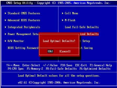
Load Optimized Defaults
You can load the default values provided by the mainboard manufacturer for the stable performance.
中国
#
GF615M-P33/ P31 肌力肌(MS-7597 v1.x)Micro-ATX 邮件编码为 1000000000000000000000000000000000000000000000000000000000000000000000000000000000000000000000

Reioh
☆
志园园是
- AM3対応지의 AMD® Phenom™ II X3/ X4 키 Athlon™ X2/ X3/ X4 키로터서 (CPU®详细介绍请点击 http://www.msi.com/index.php?func=cpuform2创建注)
HyperTransport
HyperTransport 1.0
#
NVIDIA® GeForce 6150SE & nForce 430 击战
自藏的
DDR3 800/1066/1333SDRAM(激活时置8GB)
2 DDR3 DIMMs (240 1/5V)
(荷兰:龍達海普服务网)
LAN
Realtek® RTL8111DL®の用10/100/1000 LAN対照(GF615M-P33)
Realtek® RTL8103EL® 10/100 LAN 软件 (GF615M-P31)
0
Realtek® ALC888S/ ALC889® 100000000000000000000000000000000000000000000000
7.1该日上口口
Azalia 1.0和
IDE
IDE互1
Ultra DMA 66/100/133, PIO及brss马斯托制作动多司
SATA
4个的SATA3Gb/s当机到机用
RAID
RAID0/1/5/10将资源绑定在SATA1~4
晋昱叫
晋罗司王旦1
1 FDD with 360 KB, 720 KB, 1.2 MB, 1.44 MB 同 2.88 MB
KuN
-
ACKSHERELIGUMAKNGTJHREHHTGADPHANJTHOHTBEN,HTTHT"HTp://www.msi.com/index.php"oetshkchhichhchhchhchhchhchhchhchhchhchhchhchhchhchhchhchhchhchhchhchhchhchhchhchhchhchhchhchhchhchhchhchhchhchhchhchhchhchhchhchhchhchhchhchhchhchhchhchhchhchhchhCH
吳
则用是的,如
huidweerher
ATX24FJFJFJFJFJFJFJFJFJFJFJFJFJFJFJFJFJFJFJFJFJFJFJFJFJFJFJFJFJFJFJFJFJFJFJFJFJFJFJFJFJFJFJFJ
CPU Specifications (CPU Specification)
Adjust CPU FSB Frequency (CPU FSB 썸과수 죽지) (MHz)
I 告默录电 CPU FSB 即可。
Adjust CPU Ratio (CPU bit to 0)
Adjusted CPU Frequency (主锁则CPU主卡数) (MHz)
i
Memory-Z (AnMoRi-Z)
DIMM1~2 Memory SPD Information (DIMM1~2 返回 SPD 防爆)
Advance DRAM Configuration (GoQ DRAM Nx)
Bank Interleaving (萌克入侵)
Press DEL to enter SETUP
Advanced BIOS Features
Integrated Peripherals
BIOS Setting Password
Current CPU/ DRAM Frequency
CPU Technology Support
Adjust CPU FSB Frequency (MHz)
Adjusted CPU Frequency (MHz)
Adjusted DRAM Frequency (MHz)
Adjust PCI-E Frequency (MHz)
CPU/LDT Spread Spectrum
Press DEL to enter SETUP
Advanced BIOS Features
Integrated Peripherals
BIOS Setting Password
Current CPU/ DRAM Frequency
CPU Technology Support
Adjust CPU FSB Frequency (MHz)
Adjusted CPU Frequency (MHz)
Adjusted DRAM Frequency (MHz)
Adjust PCI-E Frequency (MHz)
CPU/LDT Spread Spectrum
KOMHOENTbI CNCTEMHOI NaTbI
XAPAKTEPNUCTIKN
Пюцeccор
PioeessopbI AMD Phenol II / Althon II / Sempron B KOHcTpyKtBe AM3. (IJIa IONyEnHcAMoHOBn HNfoPmaQmO o CPU, nocTeHTe caIT http://www.msi.com/index.php?func=cpuform2)
HyperTransport
HyperTransport 1.0
Unncet
NVIDIA® GeForce 6150SE & nForce 430
PamrTb
DDR3 800/1066/1333SDRAM(Max.8GB)
3a cnota DDR3 DIMM (240kOH T 1.5V)
(3a dononHnTeBno INHΦoPmaUeN o nopeRexBaembX MoyIpy NocTeTneCaih://www.msi.com/index.php?func=testreport)
LAN
Плобдөрхка 10/100/1000 LAN на чincete Realtek® RTL8111DL (GF615M-P33)
■Иип подөрхька 10/100 LAN на чинсerte Realtek® RTL8103 (GF615M-P31)
Aydno
INTerpnpoBaHHbYuNCeT Realtek ALC888S/ALC889
Aydno 7.1 c rIbKm npeHa3NaeHnem pa3bEmOB
CoBmecTnMoCTb co cneunfkaunei Azalia 1.0
IDE
1 nopT IDE
Подэржka рекимов pa60ы Ultra DMA 66/100/133, PIO& Bus Master
SATA
4 nopTa SATA 3Gb/s noDpeKmbaOT 4 npBIOOB SATA 3Gb/s
RAID
SATA1\~4 noDnepKnBaIoT peKmbl RAID 0/1/5/10
Φnonnn
1ФJIOONnnoT
Подержka 1 FDD c 360Kb, 720Kb, 1.2Mb, 1.44Mb u 2.88Mb
KoHHeKTopbl
3aDne nanei
-1PS/2npTMbIu
-1PS/2npTknabnAtypb
- 1 nopT COM
- 1 nopT VGA
- 1 napannelbHbI nopT noDepxNBAeT pexmbl SPP/EPP/ECP
- 1 pa3beM LAN
- 4 nopTa USB 2.0
-63ByKOBbIX pa3beMOB Cn6kIM npeHa3NaeHHeM
Pa3bEmbl,yCTaHOBHeHHbIeHaIIaTe
- 2 pa3bema USB 2.0
- 1 pa3bem SPDIF-Out
-1pa3bEmIgnoNIOaynoHa nepeHnnaHei - 1 pa3bem CD-In
-1pa3bemTPM(onuohalbHO) - 1 pa3bem DaTcNka OTKpbBaHnna Kopnyca
- 1 nepeknioateiannapathoro pa3roha FSB (onuohalbho)
CnotbI
1cnotPCIExpress 1.0× 16
1cnotPCIExpress1.0x1
2 cnoTa PCI, noDnepKka INItepeeca PCI uHbIC nTahHeM 3.3V/5V
ΦopM ΦakTop
Micro-ATX (24.4cm X 20.0 cm)
Kpereenne
6OTBepctn DnKpeHneHn
EcnI BAM Heo6xoIMIO pRIO6bCTN AKeCCSYapBI N/INN y3HATb apTIKyB aWero I3dien, 3Ty INHOpMaUIO MOXHO NaHTB INTEpHET Ha Be6 caITe NO aDpecy http://www.msi.com/index.php
3ADHЯ PAHEJIb
3aHnaH naHbI npedocabnre cneyuOuNcpepaBembl:
YCTAHOBKA OBOPUIOBAHIN
3Ta rnaBa nocBraIeHa BnOpocAm yCTaHOBKn Ipoceccopa, MoDyIe NamaTn, n nnat paacIneRnA, TAKKe yCTaHOBKe nepeMbueK HcNCTEMNoIate. B rnaBe TaKKe pacCKa3bIbAeTcO ToM, KAp NOkDIOuOaTb BHeUHNe YcTpOcTBA, TAKKe KaMblS, KNaBnATpy, n T.D. PnY cTaHOBKe o6OpyDoBAnH 6yDbTe BHNMaTeIbHbI, CneDuYe Yka3aHnM no YcTAHOBKe.
YctahOBka npoecccopa n BENTINrTopa dIg AM3
Bo n36eJahnne nepepeba npn pa6ote 06raatelHo yCTAHOBIne BHTINaTOp npOeCCopa. OndHOBpEmHHo, YTObIy bEniunHt bennopaccenBaHme, y6dInTeBb TOM, Yo HAnHeCn cNoI TnIOnnpoBODJaIe NaIbHa npOeCCope npn yCTAHOBKe BEHTNIAToPA.
CnedyTe daHbmy kya3aHnM dny npabInbHO uCTaHOBKn. HenpabInbna yctahOBka npBBeD T NOBpeXdHIO pOucecoppa n CnCTeMHo PnAtbl.
1.Пдниммпь Вергкалhoe полженирьчakон,在纳亚姆斯сб60kyрабз.
2. 06pntte BnImaHne Ha 3oToTu cTpeNky (gold arrow)Ha CPU.OHa DOnJXHa 6bItb paCNoJoxHe TaK, KaK nokazao HApncyHke.CPU MOKHO BCTaBt ToIbKO npn erO npabInbHOBOpNEHTaUIN.
3.Пи npabnblhoуctahOBke CPU ero kOHTakTbI NOHOCtBO BOyUT B pa3BeM,Иnx He 6yETBnHO.NOMHITE,TOHIOble pnpmeHENe CInblp npCytahOBke CPU moKet BbIbTaBcpE3Hbne nobpekdeHnCtCEmHo nPaTbI.
4.Akkyapatrno pnpxkmnte CPU kpa3bemyu andyctne tpaHaxok. Pocokby CPU npn onnyckanHH paHxakka MOKET nepeMeCTTbC, octopOKHO npKMMnte CPU nIbIaMn BcHTpe TAK, YTO6bl OH npabInlbo H noNIOHcTbO 3aФHKcPobAONB B pa3bEme.
5. Pâzměctnéte Běvěnátropán Há yzéne kpenětnéhy. Bvháča zhážěnité odoh ero kpaí.
6. 3aTeM HaxkMTe Ha dpyroI kpaI, Tc0bIy yctahOBnTb padmToH paY3en KpennEnHa. HauHtBe lyhar fikncsui n noDhIMntEero.
7. 3aФИнсчypriTe pадиатор Дальншим 黝оворотом рьага.
8. IopKIOHOTe Ka6Bb BENTINaTOpa Cpu K COOTBeCTByKOUcEMy pa3bEmy CNCTEMMOI nPbTIb.


BHIMAHHE
* OToIpaFmN CnCTeMHo NnA tB B 3OM pa3dene npnbEeHb TOnIbKO nIa demOHcTpaun yctahOBm BEHTnIyTopa IpnoueCCOPa oN Socket AM3 CPU.BHeuHNI BnBaueM moEIN MoKeT OTnUaTbcraOt npnbEeHHoro 3decb.
* Pnir oToCoEiHEnHe nnKcNpyUoIero pbHaRa Heo6xOdImo cObIaDabT octopoxHocB, TaK kpaarNoOpnykMHe n npri OTyckaHm OH BepHTC C xDCHOe noTOXKeHHe.
YCTAHOBKa Mdyne namrtn
- Moynu namaŋTH ImeOT ToIbKO anHy npOe3B cepeiHne. Moynb BoYedT B pIa3em ToIbKO npI prAwnbHnO iOpEnTAunu.
- BCTabbTe MoyIb B BEPTnKaIbHOM HapPabIeHm. 3aTem HaxMnte Ha Hero, YTO6bI zOIOueHbI KOtAKbI rIy60KO norp3yInncB B DIMM cnot. 3oNtBe KoHTaBc EBaBnbl, eCIN MOyIb NaMTn npaBilbNo pa3MeueHb B DIMM cnot.
3.Пл actikOBe 3aueJeknHa o6oXn KOHcax pa3bema 3akpoHTcR ABTOMATNHeCKn

BHIMAHHE
- Modynln DDR3 He bAaMOna3MeHReMb c ModynMaMn DDR2, n CTanIapr DDR3 He IMeet o6bpaTHoCobMeCTmocTeN. MoDyIb naPmT DDR3 cneJyET yctahabNtBATb Tolsko B paaBem DDR3.
*IpaobToBbDByxKaHaHbHompeXmmeybeHtceb,yTOBa3bEmaxpa3hIx KaHaNoB yBaCtaHOBnHebMoynOndHO rTnA OINHAKOBOEMKoCTN.
* Yto6bI cInTeMa 3aRpykanaB, BHaayane yctaHOBnTE moynb B pa3bEm DIMM1.
24-KoHTaKTHbI pa3bEm 6Ioka nITahnA ATX: JPWR1
3TOT pa3bEM no3BONJET NOKNIQUATb 24-KoHTaKTHbI b6NOK pNTAHnA ATX K CTNEHMH nIATE. NpeED NOkNDIOUHEm y6eDInTeCb, YTO BCE wTbIPsKn pa3bEMA ot bNOKA pNTAHNPOBHBie, IN OH npABINbHO copneHTnpOBAH. IINTHO BCTAbTeERO bPA3bEM HA cNCTEMHnPnATE.
ATX 4-KoHTaKTHbI pa3bem 6Joka nItaHn: JPWR2
3T0t pābēm nīṭaḥn 12B mCnɒlβyěTc dIra oEcbnečeHn nɪtānɪya npóecoppa.
BHIMAHHE
- Ybεdntεcb, ζτο BCE KOHHeKTOpbl έπιθηλΑXT πραβυMbno ΠοδκηύηeNb.
HactoerhboKeponohyTeCnONb3OaBt6NkOHTAHN350BT(nBbIe) DnEcbHeHcTbnbHcyNTChTeMb.
Pa3bEm FDD:FDD1
3TQTpaBempoIeepxHbAeFTpONnniDnCKNEmKoCTbO 360KB,720KB,1.2MB, 1.44MBn 2.88MB.
PazbEM IDE:IDE1
Pazbem nopepkjBaAeT noeknlochHne XeCTKHX DnCKOB IDE, ONTNUecknx DnCKOB nDpyrIX IDE yctpOCTB.

BHIMAHHE
Pnno ndknoeHH mDyX yctpoiBCT hA OHm Kabe, cnedyet yctahOBntb yctpoiBa pekim master / slave nocpeCTbOM yctahOBKn pepeMbYek. 3a nHTCPTKUJIAMM OBPATNTteB k DOKUMEHTaUNI HZOTOBHTEN yCTPOCTBA.
Pazem Serial ATA: SATA1 ~ 4
Pa3bEm Serial ATA - 30 ByCOKOOPCOTNOH nort HENTPefCa Serial ATA. 3TOT pa3bEm p03BONJET NOKNIQHTB ToNko ODO yCTPOICTBO Serial ATA.
BHIMAHHE
IVsEgeraTe pe3kIX mIri6OB Ka6eRa Serial ATA. B npotBnHOM cnuyae MOryT BOBHKNHTb notepn dAnhix npi nepeDaue.
PazbemblntaHnBentnIyTopo:CPUFAN, SYSFAN1
PazbEmbl NtHAnaB BENTNIATOPOB NOdEperKXBAAOTB EBTNIIATOpblc NITNAHEM +12 B.PnI NOkDIOUeHN Heo6xOIMO NOMHTb, YK cPakbN npobod ONDkNOHaTcER K UINHe +12 B,aCepb- b-K 3EMe GND.EcN CnCTeMHNA Ptna TcOePKHT MInKPOCXemy AnnapathrO MOnHOTpHnA, Heo6xOIMO nCnOJb3OBatb CneuAlNbHbe BENTNIATOpblc DaTcHKOM CKOPoCTn DnpeaNt3aUM FyHKUynPABNEHN BENTNIATOpOM.

Pa3bem S/PDIF-Out:JSP1
3ToT pAsbem nCOnIb3yETc4 dnn PnOKnIOUeHn HInTePcEma S/PDIF (Sony & Philips Digital Interconnect Format) dnnpepaun 3Byka B UΦpOBOM φopMaTe.
Pa3bEm CD-In: JCD1
3T0t p3bem npedn3a3nueH dnn noDknIOeHHI DOnOHNHTbHO rayno Ka6Ebn.
PazbemblnnoKluOeHnnepeDne nnHeJ:JFP1,JFP2
3TN pa3bEmbl 6oceNnBaHOT nOdkIOueHne KHOOK nIHMkATOPOB nepeDnei naHEn. JFP1 cooTBeTCTByeT cneuФнkauzin Intel® Front Panel I/O Connectivity Design Guide.
Aydno pa3bem nepedne nahan:JAUD1
PazEm noBertn noKInOHT yAnIO na HepeNen HaneIN. OH COOTBETCTBYET cneIFmKauinl InteF Front Panel I/O Connectivity Design Guide.
Pazbem USB nepedne naneJUSB1/JUSB2
Pa3bem, KOTOpBIO COBMeTm CO cneuΦnKauniei Intel® I/O Connectivity Design Guide, upeJeHn Tn oNkIoUeHnra TAKnx BbCOKoKoPocSthIx nepuΦepuHnBx yctpoCTB kA K USB HDD, UΦpaBbIX KaMep, MP3 pIeepob, npInTePob, moDeMoB nT.D.

Pa3bEM TPM MoyJn: JTPM1 (onuohalho)
3T0T pa3bEm ppeHa3aHueN dno nnKIOUeHN TPM (Trusted Platform Module) MOyIy. 3a DoONHTeBHOIN HFOpMaueMn BO3MOXHOCTMn IcNOIb3OBAHry o6aPITTeB K yPKOBoCTBy nTnAPoMBy 6e2onAChOCTn TPM.

Pa3bem DaTUnKa OTKpbIbAHnK Kopnyca: JCI1
K TOMY KONHEKTOPY NOKNIOVAETC KABeB DaTnHa KOTKpbIBAHnN KOPnyCA, yCTAHOBENHb N B KOPNYC. PnI OTKpbIBAHnN KOPnyCA erO MEXAH3M AKTNB3NPyETc. CStema 3aONOMHaET 30 Co6bITne H BiDaET npDeynpExdHe n Ha 3kaPn. PpeynpExdHe MeKHO OTKnIOHtB N HactpoiKaX BIOS.
INHdkaTOP COCTOHNAPS:LED1 (onuohalho)
3TNHnDnKatopb APS (Active Phase Switching) LED nok3aIbaIOT peXIM pa60tBuNCTOHNKa NpOeecoppa. INHOpMaunO o cOToHN HnDnKaTOpOB npBBeDeHa TabNue.

Main Page (OchOBHoe MeHIO)
Standard CMOS Features (CTaHdapTHbIe yHKm CMOS)
3TO MEO HIO 0BONJET YCTAHOBINT BCHOBHIE NAPAMETbI KOHNIGYPAaUNI CHTEMbl (DAyT, BPMAE, n T..d.)
Advanced BIOS Features (Доюнтьньгд Функш BIOS)
3To MeHIO nCnOJIb3yETcI dIa HAcTpoKn CneUaJIbHbIX fHyKcIINBIOS.
Integrated Peripherals (BCTpoehhble nepupepnhbye yctpoicta)
3TOmEHNOIbEyETcJnAHaTcPOIKnMapaMeTPOB BCTPOEHNbIX npHHePnHbIXyctPOCTB.
Power Management Setup (Hactpoika ynpablenia nitaHnem)
3TO MEHIO N03BOJAreT 3aDaTb npaMeTpbl ynpaBneHnI NITAHmE CNTeMbI.
H/W Monitor (MoHTop annapaTHou actn)
3TOT nyHKT OTO6pKaet COCTOHNe annapathOH Yactn PIK.
BIOS Setting Password (Паров дocун К hashpoikam BIOS)
3TO MEHIO NcNOJIb3yETcra, YTO6bl 3aadTb napOJIb.
Cell Menu (Mehio nra pa3roha)
3TO MEHIO NOBBOJET YNPABTb TAKTOBIMu cAChTOAMn HAnPRAKEHMAIMn PnI PAHORe CTCHMEL.
Load Fail-Safe Defaults
3To MEOHIO NCON5yETA IN 3aqrpy3n 3haeHNBIOS,yCTaHOBENbIX npno3ABTINEMENI TO CTsInbHOB PAoTBi CNCTMEL.
Load Optimized Defaults (YctahOBntb onTImmaIbHbIe HAcTpOki)
3TO MeHIO IcNOpIbEycterD qy IcTAHOBm HACTPoeO INATOBOTeTEnI DnI ONTMALBOI PPOINBOIDENTBHOCTN CHTEMHNO IPIaIb.
Save & Exit Setup (BbIXoD c coXpaHHeHem HactpoE)
3aIncb n3MeHEni B CMOS n BbIXoD n3 peKIma NaCTpOKn.
Exit Without Saving (BbIXoD 6e3 coxpaHEnn)
OTmeHa BcEx N3MeHeHn N bIXoD n3 pexIMa HaCTpOKn.

Cell Menu
Current CPU/ DRAM Frequency
3TNyHKtblnok3aBbAoiTeKyuIyo Yactoty CPU nCKopocbTnamrToN.ToBko dnyTHEN.
CPU Specifications
HAnKMMte
CPU Technology Support
Hakmite Enter] nBxOda b NOpdmHeo. BnOpdmHeo noka3aHbIy TeHONIOrnn, KOTOpbeN OndepKmbAioTcB yCTahOHBoJIeHN CPM.
AMD Cool'n'Quiet
TexhONORa Cool'Quiet No3B0Jare 3e4KtHbHO DnHAMMueckn 13MeHNrTaCTOy CPU n3hePronTOpe6NEHNE CHTeMbI.
BHIMAHVE
YtObIy b6 eJntbc r B TOM, YTO texHONIOHc Cool'Nyt BKNUChEnu npabotaert npabInbNo, Heo6XdoHIMO:
- 3aɪtɪn bɪ noprammMy BIOS Setup,ɪn bɪbɪbpatr Cell Menu. Haidɪnte AMD Cool'nQuiet noct Cell Menu, yctənəbiər er o'Enabled".
- B Windows BBb6epHTe [Start]->[Settings]->[Control Panel]->[Power Options].BoiDnTE B Power Options Properties, BBb6epHTe Minimal Power Management B Power schemes.
Adjust CPU FSB Frequency (Mfμ)
3TOT nyHKT no3BONJET BbIbpaTb YacToTy FSB npoceccopa.
Adjust CPU Ratio
3TOT NYKTH ICNOLBAYETC dner pyreynipOBKO MHOKNTEI npOeCCPO. OH DOCTyHN ToNtko TOrda, KOrda npOeCCOP NoDpekXBAeT 3Ty FyHKnIOA.
Adjusted CPU Frequency (Mμ)
3TOT nyHKT noka3bIaBae TekuIyU qactOty CPU (FSB x Ratio).ToJIbKO dIyTeHnI.
Memory-Z
Haxmnte
DIMM1~2 Memory SPD Information
Hajmnte
Advance DRAM Configuration
Haxmnte
DRAM Timing Mode
3TOT nyHKT no3B0IeR abTOMaTHUeCKn onpeJeIb Tce BpeMeHNbIe napametbI DRAM. Ipi yctAHOBKe 3haueHEnia [DCT 0], [DCT 1] iIN [Both], HekOTOpBe nyHKTb NOBRAHOTcN cTaNyt DOCTyNbI. DCT 0 KOHTpONIpyeT Kahan A n DCT1 KOHTpONIpyeT Kahan B.
1T/2T Memory Timing
Pn yctahOBke DRAM Mode B [Manual], 3T0 TnyHK CTaHOBtca DoCTyNHbM. 3T0 TnyHK ONpeDeneT KcOPOCT bByIaHcKOMaHd SDRAM. Bby6op [1T] nepeBodT cHrHaNb hKOTpONeP SDRAM B pexm pa60tBu (T=KaTt REhepatOpA). Bby6op [2T] BkIIOuAe TcHrHaNb hKOTpONeP SDRAM B pexm pa60tBu co CkOpcOtBu 2T.
DCT Unganged Mode
3TOTnyHKHCN0B3yETc4Ia6bEaHINeHbYdByx64-6nTHbIXDCTB OaHIN12 8-6nTHbINHTpeFbeC.
Bank Interleaving
Bank Interleaving JIJIETcB BAXHIM napametpOM, BINHOUMM HApON3BOJNTeJIbOCT naTmI. Ero BKOJUeHne no3BOJaTeT o6paatbcK HECKOLKM 6BANKAM nAMrTn ODHOBEMEHo
Power Down Enable
3TOT nyHK T KOHPTONIPYET PABOTY TEXHOORM N 3HEPROC6epeXHeHN. PnO tCYCTBmB opaeeHH K nAMTN B TEeHHE KEOTOPO R BpEMEH, CNTcTeMa bOMATCHENQ YMeHbSAaETIANTAHNE IINr nAMTNs.
MemClk Tristate C3/ATLVID
3TOT NYHKT N03BOJENT BIKHOATb/BbIKHOATb PEXKIM pa60tbl c TPEM COCTHOARMOB BO BPEM C3 n ATLVID.
FSB/DRAM Ratio
3TOT nyHKT no3BONJET perynnpoBaTB qactOy FSB n DRAM.
Adjusted DRAM Frequency (Mf)
3TOT nyHKT noka3bIbaET kkyuO yactOtynamrT.Nolko dnyTeHnA.
HT Link Speed Configuration
Haxmte
HT Link Speed Auto
Pyr yctahOBBe B [Enabled], cHCTeMa aBToMaTHuCheKn OnpedEnaTe KcOpOCTb 1nHHI HT.
HT Link Speed
3TOT nyHKT no3B0BraE rYCTaHOBnBt cKOpOCTb nepeDaun no shne HyperTransport.
Adjust PCI-E Frequency (MΓu)
3TOT nyHKT NO3BONAEYCTAHOBNTb yactOTy PCIE.
Auto Disable DRAM/PCI Frequency
Pn yctahOBke 3aueHInn [Enabled], CnCTeMa OTKnOHT HeICNOnb3yEmbte pa3BeMb namrTn PCI, TTO npBedeT K cnHexeHIO YpOBHr 3NeKtPOMaHrTHbIX nomex (EMI).
DRAM Voltage (V)/ NB Voltage (V)/ HT Link Voltage (V)
TOT nyHKT no3Bolaret perynpobatb hnapxkeHne CPU, namrtn uynnceta.
CPU/LDT Spread Spectrum
3TOT nyHKI hONJIbEyetc TnB KNUOeHn/ BkNUOeHn TEXHOrOg CPU/LDT (HT Bus multiplier) Spread Spectrum.
PCIE Spread Spectrum
3TOT yHKT NcNbONbEyTCaIy BkNcHcHb/ BbKnOcHcHbTexHONOrn PCIE Spread Spectrum.
SATA Spread Spectrum
3TOT YNHKT NCOINB3yETcA DnRA BKNIOChENr/ BbKIOChENr TEXHOrNr SATA Spread Spectrum.
BHIMAHHE
Ecni y BAC het npobnem c nomexamn, octabte 3hauehme [Disabled] (stanpeuho) dnyuwec stcbnbohcnt u npou3b0dntelbhoctn. Ondako, ecni y BAC BO3HnKAIO TneKpromarHnthe bomex, Bb6epTe Spad Spectrum dlya uy mHeBHeHia.
* Yem 6oIbIwe 3naueHne Spread Spectrum, tem Hnke oydeT ypoBHeN b3eKpOMaTHnBix nomex, Ho cIncTeMa stahet Mehee TaobnBHO. Iyra BbIObe npXODaJero 3naueHne Spread Spectrum, CbePbTeCb co 3naueHernM ypoBHeN 3eKpOMaTHnBix nomex, yctahOBnEHHbx 3akOHdaTeJIbCTBOM.
He 3a6yblte 3a9pntHb IcnoIb3ObaHne FyHKcMn Spread Spectrum, ecn bIy [pa3oHnHeT] CNTeMHy IO nATy. 3To Heo6xOJIMo, TAK KAK daxke HeoNlsuoi Dpe6e3r CRIHANOB TAKTOBORO reHEPATOPa MOKeT npINBeCTN K OTKa3y [pa3oRHaHHOrO] IpoUeCCoppa.
YctaHObKa 3HaueHn no yMOnJauHnIO
Ia 3abHbno a60bT bCt CteMbl Bb moKete 3ary3ntb 3HaeneBHOS, yctAHOBHeBnpeoN3BOdHTenemCtEHmO nPbTa.

简体中文
简介
Press DEL to enter SETUP
(按DEL键进入设定)
CPU Specifications (CPU 属性)
CPU/LDT Spread Spectrum (CPU/LDT 频展)
硬體超頻FSB開關:OC_SW1(選配)
Press DEL to enter SETUP
(按DEL键進入設定)
Integrated Peripherals (整合型週邊)
使用本選單設定整合型週邊裝置。
Adjust CPU FSB Frequency (MHz) (调整CPUFSB频率)
Adjusted CPU Frequency (MHz) (調整後CPU頻率)
Press DEL to enter SETUP
(千米一押七设定画面呼出)
CMOS Setup Utility - Copyright (C) 1985-2005, American Negatrends, Inc.
Standard CHOS Features
Advanced BIOS Features
Integrated Peripherals
Power Management Setup
H/V Monitor
BIOS Setting Password
Cell Menu
Load Fail-Safe Defaults
Load Optimized Defaults
Save 8 Exit Setup
Exit Without Saving
Move Enter:Select +/-Value F10:Save ESC:Exit F1:General Help
F4:CPU Spec F5:Memory-2 F8:Fail-Safe Defaults F6:Optimized Defaults
Configure Time and Date. Display System Information...
002.61 (C) Copyright 1985-2006, American Megatrends, Inc.
CPU Technology Support(CPUtekNoJ-safo-1)
CPU/LDT Spread Spectrum
CPU/LDT (HT Bus multiplier) Spread Spectrum特性を有効/無効にしま�。
PCIE Spread Spectrum
- FCC-B RADIO FREQUENCY INTERFERENCE STATEMENT
- Notice 1
- Notice 2
- PART NUMBER
- COPYRIGHT NOTICE
- TRADEMARKS
- REVISION HISTORY
- SAFETY INSTRUCTIONS
- CAUTION
- 警告使用者
- ENGLISH
- DEUTSCH
- SPECIFICATIONS
- Processor Support
- HyperTransport
- Chipset
- Memory Support
- LAN
- Audio
- IDE
- SATA
- RAID
- Floppy
- Connectors
- Back panel
- On-Board Connectors
- Slots
- Form Factor
- Mounting
- REAR PANEL
- HARDWARE SETUP
- CPU & Cooler Installation for AM3
- IMPORTANT
- Installing Memory Modules
- ATX 24-Pin Power Connector: JPWR1
- ATX 4-Pin Power Connector: JPWR2
- Floppy Disk Drive Connector: FDD1
- IDE Connector: IDE1
- Serial ATA Connector: SATA1 ~ 4
- Fan Power Connectors: CPUFAN, SYSFAN1
- S/PDIF-Out Connector: JSP1
- CD-In Connector: JCD1
- Front Panel Connectors: JFP1, JFP2
- Front Panel Audio Connector: JAUD1
- Front USB Connector: JUSB1/ JUSB2
- TPM Module connector: JTPM1 (optional)
- Chassis Intrusion Connector: JCI1
- APS LED Status Indicator:LED1
- Clear CMOS Jumper: JBAT1
- Overclock FSB Switch: OC_SW1 (optional)
- PCI Express Slot
- PCI Slot
- PCI Interrupt Request Routing
- BIOS SETUP
- Press DEL to enter SETUP
- Main Page
- Standard CMOS Features
- Advanced BIOS Features
- Integrated Peripherals
- Power Management Setup
- H/W Monitor
- BIOS Setting Password
- Cell Menu
- Load Fail-Safe Defaults
- Load Optimized Defaults
- Save & Exit Setup
- Exit Without Saving
- Current CPU/ DRAM Frequency
- CPU Specifications
- CPU Technology Support
- AMD Cool'n'Quiet
- Adjust CPU FSB Frequency (MHz)
- Adjust CPU Ratio
- Adjusted CPU Frequency (MHz)
- Memory-Z
- DIMM1~2 Memory SPD Information
- Advance DRAM Configuration
- DRAM Timing Mode
- 1T/2T Memory Timing
- DCT Unganged Mode
- Bank Interleaving
- Power Down Enable
- MemClk Tristate C3/ATLVID
- FSB/DRAM Ratio
- Adjusted DRAM Frequency (MHz)
- HT Link Speed Configuration
- HT Link Speed Auto
- HT Link Speed
- Adjust PCI-E Frequency (MHz)
- Auto Disable DRAM/PCI Frequency
- DRAM Voltage (V)/ NB Voltage (V)/ HT Link Voltage (V)
- CPU/LDT Spread Spectrum
- PCIE Spread Spectrum
- SATA Spread Spectrum
- 中国
- #
- ☆
- 志园园是
- 自藏的
- 0
- 晋昱叫
- KuN
- -
- 吳
- huidweerher
- ATX24FJFJFJFJFJFJFJFJFJFJFJFJFJFJFJFJFJFJFJFJFJFJFJFJFJFJFJFJFJFJFJFJFJFJFJFJFJFJFJFJFJFJFJFJ
- CPU Specifications (CPU Specification)
- Adjust CPU FSB Frequency (CPU FSB 썸과수 죽지) (MHz)
- Adjust CPU Ratio (CPU bit to 0)
- Adjusted CPU Frequency (主锁则CPU主卡数) (MHz)
- Memory-Z (AnMoRi-Z)
- DIMM1~2 Memory SPD Information (DIMM1~2 返回 SPD 防爆)
- Advance DRAM Configuration (GoQ DRAM Nx)
- XAPAKTEPNUCTIKN
- Пюцeccор
- Unncet
- PamrTb
- Aydno
- Φnonnn
- KoHHeKTopbl
- CnotbI
- ΦopM ΦakTop
- Kpereenne
- 3ADHЯ PAHEJIb
- YCTAHOBKA OBOPUIOBAHIN
- YctahOBka npoecccopa n BENTINrTopa dIg AM3
- BHIMAHHE
- YCTAHOBKa Mdyne namrtn
- 24-KoHTaKTHbI pa3bEm 6Ioka nITahnA ATX: JPWR1
- ATX 4-KoHTaKTHbI pa3bem 6Joka nItaHn: JPWR2
- Pa3bEm FDD:FDD1
- PazbEM IDE:IDE1
- Pazem Serial ATA: SATA1 ~ 4
- PazbemblntaHnBentnIyTopo:CPUFAN, SYSFAN1
- Pa3bem S/PDIF-Out:JSP1
- Pa3bEm CD-In: JCD1
- PazbemblnnoKluOeHnnepeDne nnHeJ:JFP1,JFP2
- Aydno pa3bem nepedne nahan:JAUD1
- Pazbem USB nepedne naneJUSB1/JUSB2
- Pa3bEM TPM MoyJn: JTPM1 (onuohalho)
- Pa3bem DaTUnKa OTKpbIbAHnK Kopnyca: JCI1
- INHdkaTOP COCTOHNAPS:LED1 (onuohalho)
- Main Page (OchOBHoe MeHIO)
- Standard CMOS Features (CTaHdapTHbIe yHKm CMOS)
- Advanced BIOS Features (Доюнтьньгд Функш BIOS)
- Integrated Peripherals (BCTpoehhble nepupepnhbye yctpoicta)
- Power Management Setup (Hactpoika ynpablenia nitaHnem)
- H/W Monitor (MoHTop annapaTHou actn)
- BIOS Setting Password (Паров дocун К hashpoikam BIOS)
- Cell Menu (Mehio nra pa3roha)
- Load Optimized Defaults (YctahOBntb onTImmaIbHbIe HAcTpOki)
- Save & Exit Setup (BbIXoD c coXpaHHeHem HactpoE)
- Exit Without Saving (BbIXoD 6e3 coxpaHEnn)
- BHIMAHVE
- Adjust CPU FSB Frequency (Mfμ)
- Adjusted CPU Frequency (Mμ)
- Adjusted DRAM Frequency (Mf)
- Adjust PCI-E Frequency (MΓu)
- YctaHObKa 3HaueHn no yMOnJauHnIO
- 简体中文
- 简介
- (按DEL键进入设定)
- CPU Specifications (CPU 属性)
- 硬體超頻FSB開關:OC_SW1(選配)
- (按DEL键進入設定)
- (千米一押七设定画面呼出)
Brand : MSI
Model : GF615M-P31
Category : Electronic component