
G52-75221XI - Laptop MSI - Free user manual and instructions
Find the device manual for free G52-75221XI MSI in PDF.
| Product type | Laptop |
| Brand | MSI |
| Model | G52-75221XI |
| Processor | Intel Core i7 (socket LGA1366), up to 6.4 GT/s |
| Chipset | Intel X58 (North Bridge) + Intel ICH10R (South Bridge) |
| Memory | 6 slots DDR3 DIMM, DDR3 2133 (OC)/ 1800 (OC)/ 1600 (OC)/ 1333/ 1066/ 800, max 24 GB, dual/triple channel |
| Storage | 7 SATA 3 Gb/s ports (SATA1~6 via ICH10R, SATA9 via JMicron), 2 SATA 6 Gb/s ports (SATA7~8 via Marvell), 1 rear eSATA port |
| Audio | Realtek ALC892, 8 channels, True Blu-ray Audio, Azalia 1.0 compliant |
| Network | LAN 10/100/1000 Fast Ethernet (Realtek RTL8111E) |
| USB | 8 rear USB 2.0 ports, 2 internal USB 2.0 connectors, 2 USB 3.0 ports (NEC uPD720200F1), 1 internal USB 3.0 connector |
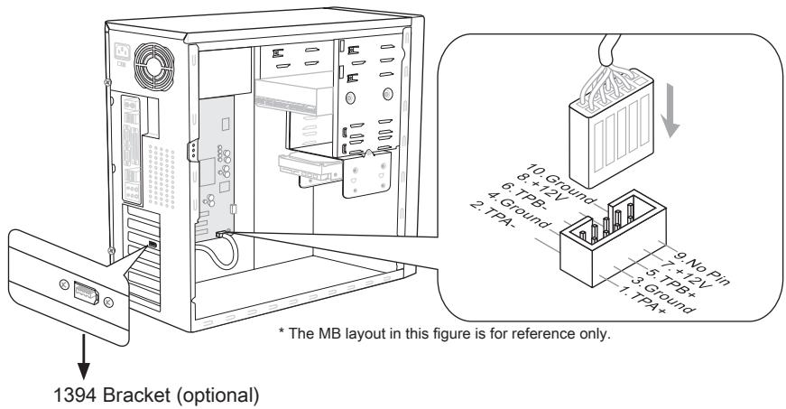
| IEEE 1394 | 2 ports (1 internal connector, 1 rear) via VIA VT6308 |
| Rear connectors | 1 PS/2 keyboard, 1 PS/2 mouse, 1 CMOS clear button, 1 optical S/PDIF, 1 coaxial S/PDIF, 1 IEEE 1394, 8 USB 2.0, 1 eSATA, 1 LAN, 6 audio jacks |
| Internal connectors | 2 USB 2.0, 1 USB 3.0, 1 IEEE 1394, 1 chassis intrusion, 1 TPM, 1 serial, 1 CD-In, 1 S/PDIF-Out, 1 front audio, 1 reset button, 1 power button |
| Expansion slots | 2 PCIe 2.0 x16, 1 PCIe 1.0 x16 (x4 max), 3 PCIe 2.0 x1, 1 PCI |
| Dimensions (motherboard) | 24.4 x 30.5 cm (ATX form factor) |
| BIOS | AMI/AWARD/PHOENIX, advanced settings, overclocking, power management |
| Special features | Supports RAID 0/1/5/10 (Intel Matrix Storage), overclocking, APS (Active Phase Switching) LEDs |
Frequently Asked Questions - G52-75221XI MSI
User questions about G52-75221XI MSI
0 question about this device. Answer the ones you know or ask your own.
Ask a new question about this device
Download the instructions for your Laptop in PDF format for free! Find your manual G52-75221XI - MSI and take your electronic device back in hand. On this page are published all the documents necessary for the use of your device. G52-75221XI by MSI.
USER MANUAL G52-75221XI MSI
The material in this document is the intellectual property of MICRO-STAR INTERNATIONAL. We take every care in the preparation of this document, but no guarantee is given as to the correctness of its contents. Our products are under continual improvement and we reserve the right to make changes without notice.
Trademarks
All trademarks are the properties of their respective owners.
MSI is registered trademark of Micro-Star Int'l Co., Ltd.
NVIDIA® is registered trademark of NVIDIA Corporation.
ATI® is registered trademark of ATI Technologies, Inc.
AMD® is registered trademarks of AMD Corporation.
Intel® is registered trademarks of Intel Corporation.
Windows® is registered trademarks of Microsoft Corporation.
AMI is registered trademark of American Megatrends, Inc.
Award® is a registered trademark of Phoenix Technologies Ltd.
Sound Blaster® is registered trademark of Creative Technology Ltd.
Realtek® is registered trademark of Realtek Semiconductor Corporation.
- JMicron® is registered trademark of JMicron Technology Corporation.
Netware® is a registered trademark of Novell, Inc.
Revision History
| Revision | Revision History | Date |
| V5.0 | First release for Europe | November 2010 |
Technical Support
If a problem arises with your system and no solution can be obtained from the user's manual, please contact your place of purchase or local distributor. Alternatively, please try the following help resources for further guidance.
Visit the MSI website for FAQ, technical guide, BIOS updates, driver updates, and other information: http://www.msi.com/index.php?func=service
Contact our technical staff at: http://ocss.msi.com
Safety Instructions
Always read the safety instructions carefully.
- Keep this User's Manual for future reference.
- Keep this equipment away from humidity.
Lay this equipment on a reliable flat surface before setting it up.
- The openings on the enclosure are for air convection hence protects the equipment from overheating. DO NOT COVER THE OPENINGS.
- Make sure the voltage of the power source and adjust properly 110/220V before connecting the equipment to the power inlet.
- Place the power cord such a way that people can not step on it. Do not place anything over the power cord.
Always Unplug the Power Cord before inserting any add-on card or module.
All cautions and warnings on the equipment should be noted.
- Never pour any liquid into the opening that could damage or cause electrical shock.
If any of the following situations arises, get the equipment checked by service personnel:
The power cord or plug is damaged.
Liquid has penetrated into the equipment.
The equipment has been exposed to moisture.
The equipment does not work well or you can not get it work according to User's Manual.
The equipment has dropped and damaged.
The equipment has obvious sign of breakage.
DO NOT LEAVE THIS EQUIPMENT IN AN ENVIRONMENT UNCONDITIONED, STORAGE TEMPERATURE ABOVE 60^ (140°F), IT MAY DAMAGE THE EQUIPMENT.
CAUTION: Danger of explosion if battery is incorrectly replaced.
Replace only with the same or equivalent type recommended by the manufacturer.
警告使用者:
For better environmental protection, waste batteries should be collected separately for recycling special disposal.
FCC-B Radio Frequency Interference Statement
This equipment has been tested and found to comply with the limits for a Class B digital device, pursuant to Part 15 of the FCC Rules. These limits are designed to provide reasonable protection against harmful inter

ference in a residential installation. This equipment generates, uses and can radiate radio frequency energy and, if not installed and used in accordance with the instructions, may cause harmful interference to radio communications. However, there is no guarantee that interference will not occur in a particular installation. If this equipment does cause harmful interference to radio or television reception, which can be determined by turning the equipment off and on, the user is encouraged to try to correct the interference by one or more of the measures listed below.
Reorient or relocate the receiving antenna.
- Increase the separation between the equipment and receiver.
- Connect the equipment into an outlet on a circuit different from that to which the receiver is connected.
Consult the dealer or an experienced radio/television technician for help.
Notice 1
The changes or modifications not expressly approved by the party responsible for compliance could void the user's authority to operate the equipment.
Notice 2
Shielded interface cables and A.C. power cord, if any, must be used in order to comply with the emission limits.
VOIR LA NOTICE D'INSTALLATION AVANT DE RACCORDER AU RESEAU.

Micro-Star International
MS-7522
This device complies with Part 15 of the FCC Rules. Operation is subject to the following two conditions:
1) this device may not cause harmful interference, and
2) this device must accept any interference received, including interference that may cause undesired operation.
WEEE (Waste Electrical and Electronic Equipment) Statement
ENGLISH
To protect the global environment and as an environmentalist, MSI must remind you that...
Under the European Union ("EU") Directive on Waste Electrical and Electronic Equipment, Directive 2002/96/EC, which takes effect on August 13, 2005, products of "electrical and electronic equipment" cannot be discarded
as municipal waste anymore and manufacturers of covered electronic equip-
ment will be obligated to take back such products at the end of their useful life. MSI will comply with the product take back requirements at the end of life of MSI-branded products that are sold into the EU. You can return these products to local collection points.

DEUTSCH
Mainboard Specifications
Processor Support
Intel® i7 processor in the LGA1366 package (For the latest information about CPU, please visit http://www.msi.com/index.php?func=cpuform2)
QPI
Up to 6.4 GT/s
Chipset
North Bridge : Intel® X58 chipset
South Bridge : Intel® ICH10R chipset
Memory Support
6 DDR3 DIMMs support DDR3 2133(OC)/ 1800(OC) /1600*(OC)/ 1333/ 1066 / 800 DRAM (24GB Max)
Supports Dual-Channel/ Triple-Channel mode *For more information on compatible components, please visit http://www.msi.com/index.php?func=testreport)
LAN
IEEE 1394
Supports LAN 10/100/1000 Fast Ethernet by Realtek® RTL8111E
2 IEEE 1394 ports by VIA®VT6308 (pinheader x1, rear panel x1)
Audio
Chip integrated by Realtek® ALC892 (True Blu-ray Audio)
Flexible 8-channel audio with jack sensing
Compliant with Azalia 1.0 Spec
SATA
7 SATA 3Gb/s ports (SATA1~6) by Intel® ICH10R and (SATA9) by JMicron® JMB362
2 SATA 6Gb/s ports (SATA7~8) by Marvell® SE9128
1 eSATA ports (back panel) by JMicron® JMB362
USB 3.0
2 USB 3.0 ports by NEC® uPD720200F1
RAID
SATA1~6 support Intel® Matrix Storage Technology (AHCI/ RAID 0/1/5/10) by Intel® ICH10R
SATA7~8 ports support RAID 0/1 mode by Marvell® SE9128
Connectors
Back panel
- 1 PS/2 keyboard port
- 1 PS/2 mouse port
- 1 Clear CMOS button
- 1 Optical S/PDIF-Out
- 1 Coaxial S/PDIF-Out
- 1 1394 port
- 8 USB 2.0 ports
- 1 eSATA port
- 1 LAN port
- 6 flexible audio jacks
On-Board
- 2 USB 2.0 connectors
- 1 USB 3.0 connector
- 1 1394 connector
- 1 Chassis Intrusion connector
- 1 TPM Module connector
- 1 Serial connector
- 1 CD-In connector
- 1 S/PDIF-Out connector
- 1 Front panel audio connector
- 1 Reset button
- 1 Power button
Slots
2 PCIE 2.0 x16 slots (PCI_E2, PCI_E5)
1 PCIE 1.0 x16 slot (PCI_E6), supports up to PCIEx4 speed.
- When you install expansion cards into the PCIEx1 slots (PCI_E1, PCI_E3 or PCI_E4), the PCI_E6 lans will auto arrange from x4 to x1.
3 PCIE 2.0 x1 slots
1 PCI slot
Form Factor
ATX (24.4cm X 30.5 cm)
Mounting
9 mounting holes
- If you need to purchase accessories and request the part numbers, you could search the product web page and find details on our web address below
http://www.msi.com/index.php
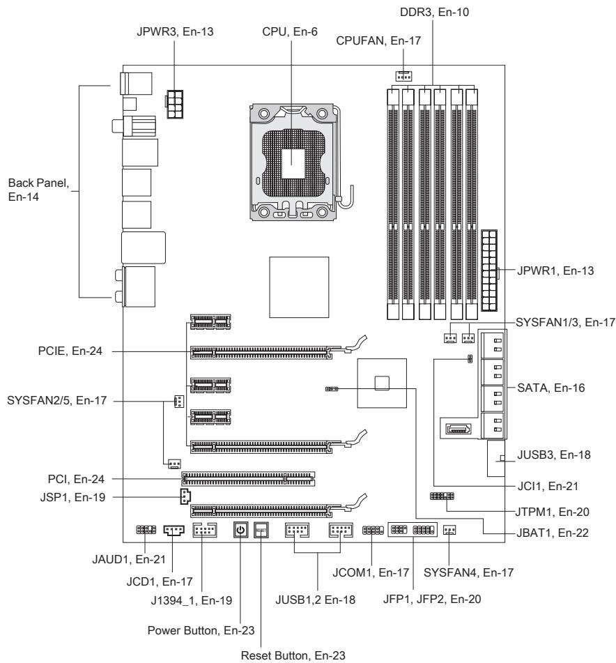
Quick Components Guide
Screw Holes
When you install the mainboard, you have to place the mainboard into the chassis in the correct direction. The locations of screws holes on the mainboard are shown as below.
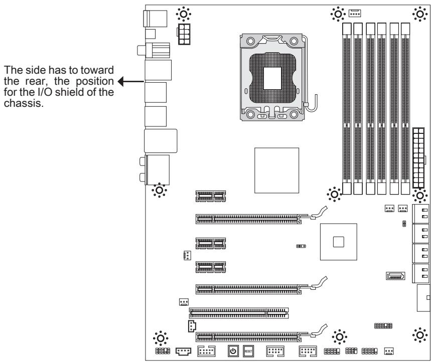

Refer above picture to install standoffs in the appropriate locations on chassis and then screw through the mainboard screw holes into the standoffs.
Important
- To prevent damage to the mainboard, any contact between the mainboard circuit and chassis or unnecessary standoffs mounted on the chassis is prohibited.
- Please make sure there is no metal components placed on the mainboard or within the chassis that may cause short circuit of the mainboard.
CPU (Central Processing Unit)
When you are installing the CPU, make sure to install the cooler to prevent overheating. If you do not have the CPU cooler, consult your dealer before turning on the computer. For the latest information about CPU, please visit http://www.msi.com/index.php?func=cpuform2
Important
Overheating
Overheating will seriously damage the CPU and system. Always make sure the cooling fan can work properly to protect the CPU from overheating. Make sure that you apply an even layer of thermal paste (or thermal tape) between the CPU and the heatsink to enhance heat dissipation.
Replacing the CPU
While replacing the CPU, always turn off the ATX power supply or unplug the power supply's power cord from the grounded outlet first to ensure the safety of CPU.
Overclocking
This mainboard is designed to support overclocking. However, please make sure your components are able to tolerate such abnormal setting, while doing overclocking. Any attempt to operate beyond product specifications is not recommended. We do not guarantee the damages or risks caused by inadequate operation or beyond product specifications.
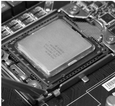
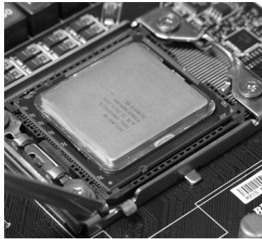
Introduction to LGA 1366 CPU
The pin-pad side of LGA 1366 CPU.
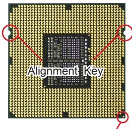
Yellow triangle is the Pin 1 indicator
The surface of LGA 1366 CPU. Remember to apply some thermal paste on it for better heat dispersion.
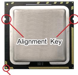
Yellow triangle is the Pin 1 indicator
CPU & Cooler Installation
When you are installing the CPU, make sure the CPU has a cooler attached on the top to prevent overheating. Meanwhile, do not forget to apply some thermal paste on CPU before installing the heat sink/cooler fan for better heat dispersion.
Follow the steps below to install the CPU & cooler correctly. Wrong installation will cause the damage of your CPU & mainboard.
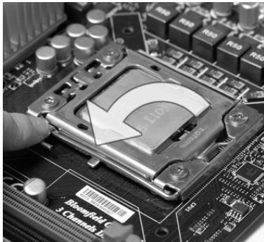
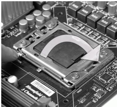
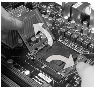
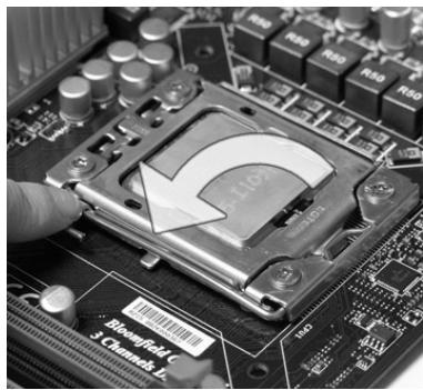
- Open the load level.
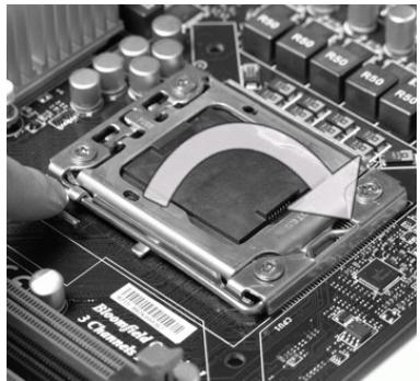
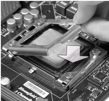
- Lift the load lever up and open the load plate.

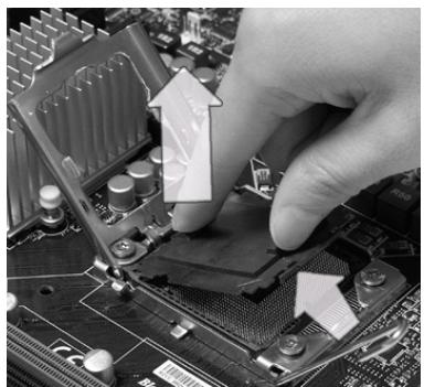
- The CPU socket has a plastic cap on it to protect the contact from damage. Before you install CPU, always cover it to protect the socket pin. Remove the cap (as the arrow shows).
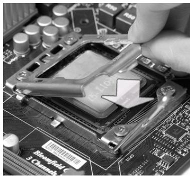
- After confirming the CPU direction for correct mating, put down the CPU in the socket housing frame. Be sure to grasp on the edge of the CPU base. Note that the alignment keys are matched.
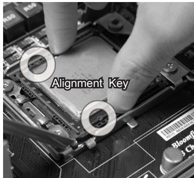
- Visually inspect if the CPU is seated well into the socket. If not, take out the CPU with pure vertical motion and reinstall.
- Press down the load lever lightly onto the load plate, and then secure the lever with the hook under retention tab.
- Cover the load plate onto the package.
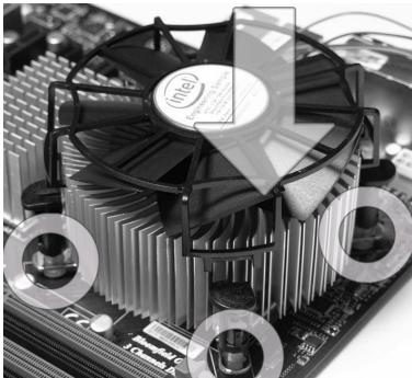
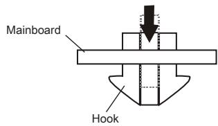
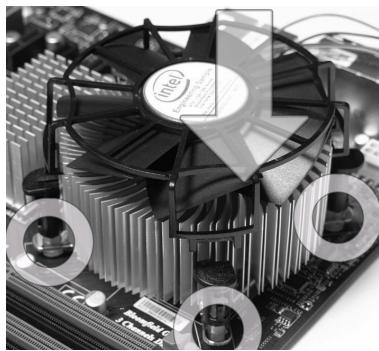
- Align the holes on the mainboard with the heatsink. Push down the cooler until its four clips get wedged into the holes of the mainboard.
Important
- Confirm if your CPU cooler is firmly installed before turning on your system.
-
Do not touch the CPU socket pins to avoid damaging.
-
Press the four hooks down to fasten the cooler.
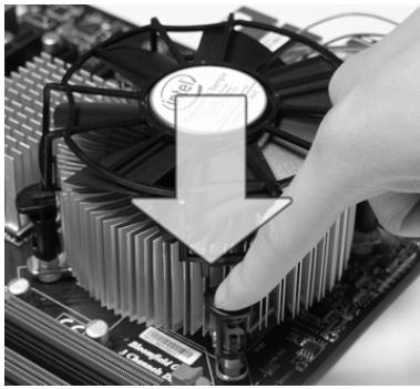
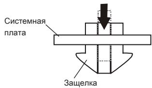
- Turn over the mainboard to confirm that the clip-ends are correctly inserted.
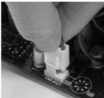
- Finally, attach the CPU Fan cable to the CPU fan connector on the mainboard.
Important
- Read the CPU status in BIOS.
- Whenever CPU is not installed, always protect your CPU socket pin with the plastic cap covered (shown in Figure 1) to avoid damaging.
- Mainboard photos shown in this section are for demonstration of the CPU/ cooler installation only. The appearance of your mainboard may vary depending on the model you purchase.
- Please refer to the documentation in the CPU fan package for more details about the CPU fan installation.
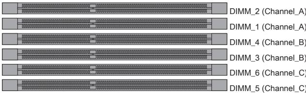
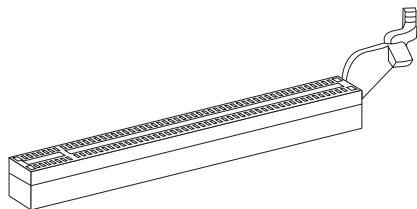
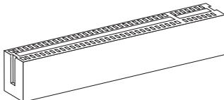
Memory
These DIMM slots are used for installing memory modules. For more information on compatible components, please visit http://www.msi.com/index.php?func=testreport
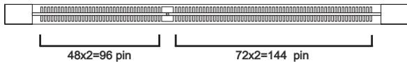
DDR3
240-pin, 1.5V
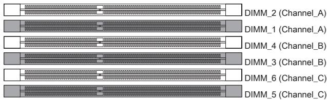
Memory Population Rule
Please refer to the following illustrations for memory population rules.
Single-Channel mode Population Rule
When you have only one memory module, please always insert it into the DIMM_1 first.


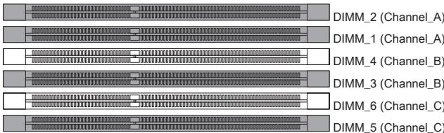
Dual-Channel mode Population Rule
In Dual-Channel mode, the memory modules can transmit and receive data with two data bus lines simultaneously. Enabling Dual-Channel mode can enhance the system performance. When you have two memory modules, please always insert them as the figures shown in below.


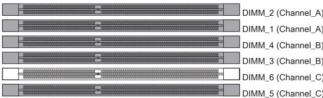
Triple-Channel mode Population Rule
In Triple-Channel mode, the memory modules can transmit and receive data with three data bus lines simultaneously. Enabling Triple-Channel mode can enhance the best system performance. When you have three or more memory modules, please always insert them as the figures shown in below.
(3)
4
(5)
6
Important
- DDR3 memory modules are not interchangeable with DDR2 and the DDR3 standard is not backwards compatible. You should always install DDR3 memory modules in the DDR3 DIMM slots.
-
In Triple-Channel/ Dual-Channel mode, make sure that you install memory modules of the same type and density in different channel DIMM slots.
-
To enable successful system boot-up, always insert the memory modules into the DIMM_1 first.
- Due to the chipset resource deployment, the system density will only be detected up to 23+GB (not full 24GB) when each DIMM is installed with a 4GB memory module.
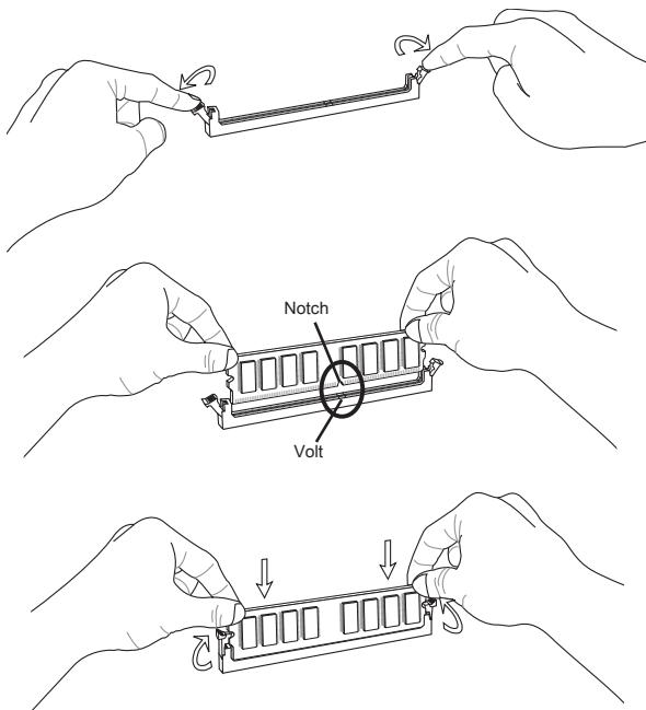
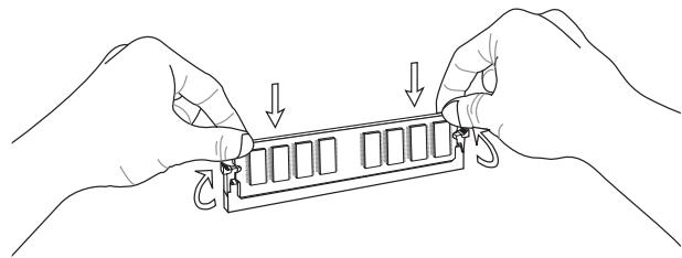
Installing Memory Modules
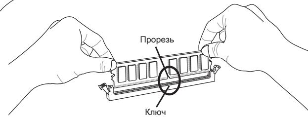
- The memory module has only one notch on the center and will only fit in the right orientation.
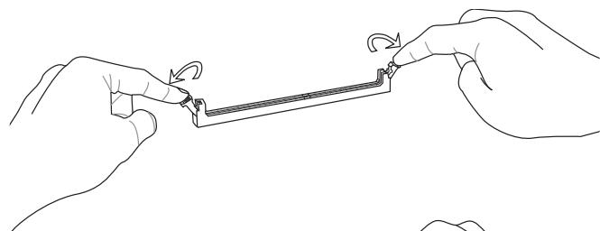
- Insert the memory module vertically into the DIMM slot. Then push it in until the golden finger on the memory module is deeply inserted in the DIMM slot. The plastic clip at each side of the DIMM slot will automatically close when the memory module is properly seated.
- Manually check if the memory module has been locked in place by the DIMM slot clips at the sides.
Important
You can barely see the golden finger if the memory module is properly inserted in the DIMM slot.
Power Supply
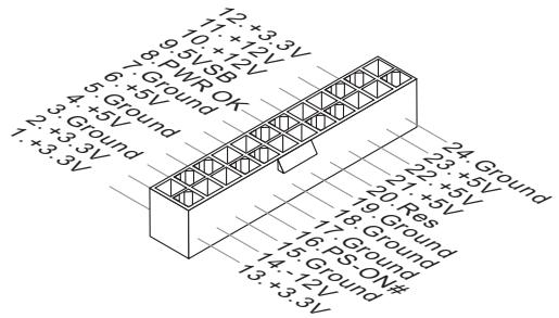
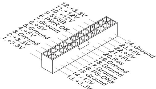
ATX 24-pin Power Connector: JPWR1
This connector allows you to connect an ATX 24-pin power supply. To connect the ATX 24-pin power supply, make sure the plug of the power supply is inserted in the proper orientation and the pins are aligned. Then push down the power supply firmly into the connector.
You may use the 20-pin ATX power supply as you like. If you'd like to use the 20-pin ATX power supply, please plug your power supply along with pin 1 & pin 13.
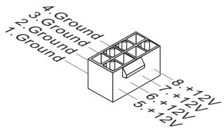
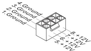
ATX 8-pin Power Connector: JPWR3
These connectors provide 12V power output to the CPUs.
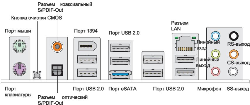
Back Panel
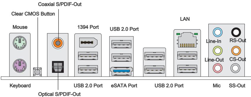
Mouse/Keyboard
The standard PS/2® mouse/keyboard DIN connector is for a PS/2® mouse/keyboard.
Clear CMOS Button
There is a CMOS RAM on board that has a power supply from external battery to keep the system configuration data. With the CMOS RAM, the system can automatically boot OS every time it is turned on. If you want to clear the system configuration, use the button to clear data. Press the button to clear the data.
Important
-
Make sure that you power off the system before clearing CMOS data.
-
After pressing this button to clear CMOS data in power off (G3) state, the system will boot automatically.
Coaxial S/PDIF-Out
This SPDIF (Sony & Philips Digital Interconnect Format) connector is provided for digital audio transmission to external speakers through a coaxial cable.
Optical S/PDIF-Out
This SPDIF (Sony & Philips Digital Interconnect Format) connector is provided for digital audio transmission to external speakers through an optical fiber cable.
IEEE 1394 Port
The IEEE 1394 port on the back panel provides connection to IEEE 1394 devices.
>USB2.0Port
The USB (Universal Serial Bus) port is for attaching USB devices such as keyboard, mouse, or other USB-compatible devices. Supports data transfer rate up to 480Mbit/s (Hi-Speed).
eSATA Port
The eSATA (External SATA) port is for attaching the eSATA hard drive.
LAN
The standard RJ-45 LAN jack is for connection to the Local Area Network (LAN). You can connect a network cable to it.
Yellow Green/Orange
| LED | Color | LED State | Condition |
| Left | Yellow | Off | LAN link is not established. |
| On(Steady state) | LAN link is established. | ||
| On(brighter & pulsing) | The computer is communicating with another computer on the LAN. | ||
| Right | Green | Off | 10 Mbit/sec data rate is selected. |
| On | 100 Mbit/sec data rate is selected. | ||
| Orange | On | 1000 Mbit/sec data rate is selected. |
Audio Ports
These audio connectors are used for audio devices. It is easy to differentiate between audio effects according to the color of audio jacks.
- Line-In (Blue) - Line In, is used for external CD player, tape-player or other audio devices.
Line-Out (Green) - Line Out, is a connector for speakers or headphones. - Mic (Pink) - Mic, is a connector for microphones.
RS-Out (Black) - Rear-Surround Out in 4/5.1/7.1 channel mode.
CS-Out (Orange) - Center/ Subwoofer Out in 5.1/ 7.1 channel mode.
SS-Out (Gray) - Side-Surround Out 7.1 channel mode.
Connectors
Serial ATA Connector: SATA1~9
This connector is a high-speed Serial ATA interface port. Each connector can connect to one Serial ATA device.
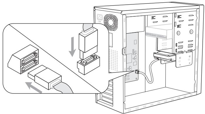
* The MB layout in this figure is for reference only.
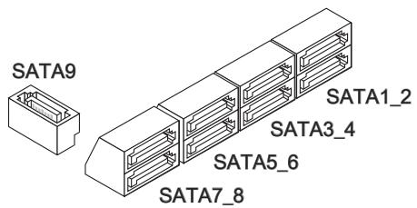
SATA1~6 (3Gb/s)
supported by Intel® ICH10R
SATA7/ SATA8 (6Gb/s)
supported by Marvell® SE9128
SATA9 (3Gb/s)
supported by JMicron® JMB362
Important
Please do not fold the Serial ATA cable into 90-degree angle. Otherwise, data loss may occur during transmission.
Fan Power Connectors: CPUFAN,SYSFAN1~5
The fan power connectors support system cooling fan with +12V . When connecting the wire to the connectors, always note that the red wire is the positive and should be connected to the +12V ; the black wire is Ground and should be connected to GND. If the mainboard has a System Hardware Monitor chipset on-board, you must use a specially designed fan with speed sensor to take advantage of the CPU fan control.
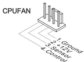

SYSFAN1~5
Important
- Please refer to the recommended CPU fans at processor's official website or consult the vendors for proper CPU cooling fan.
- CPUFAN support Smart fan control. You can install Control Center utility that will automatically control the CPUFAN speeds according to the actual CPUFAN temperatures.
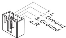
CD-In Connector: JCD1
This connector is provided for external audio input.
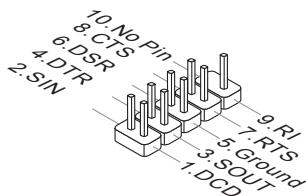
Serial Port Connector: JCOM1
This connector is a 16550A high speed communication port that sends/receives 16 bytes FIFOs. You can attach a serial device.
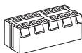
Front USB Connector: JUSB1, JUSB2
This connector, compliant with Intel® I/O Connectivity Design Guide, is ideal for connecting high-speed USB interface peripherals such as USB HDD, digital cameras, MP3 players, printers, modems and the like.
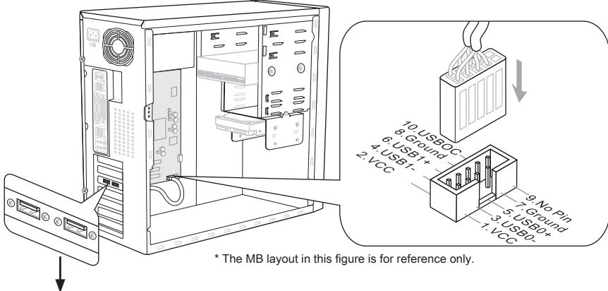
USB 2.0 Bracket (optional)
Front USB Connector: JUSB3
USB 3.0 port is backward-compatible with USB 2.0 devices. Supports data transfer rate up to 5 Gbit/s (SuperSpeed).
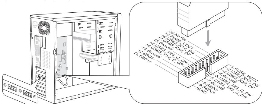
* The MB layout in this figure is for reference only.
USB 3.0 Bracket (optional)
Important
- Note that the pins of VCC and GND must be connected correctly to avoid possible damage.
- If you want to use a USB 3.0 device, you must use the USB 3.0 cable to connect to the USB 3.0 port.
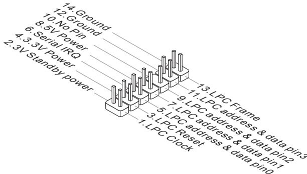
IEEE1394 Connector: J1394_1
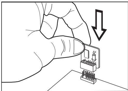
This connector allows you to connect the IEEE1394 device via an optional IEEE1394 bracket.
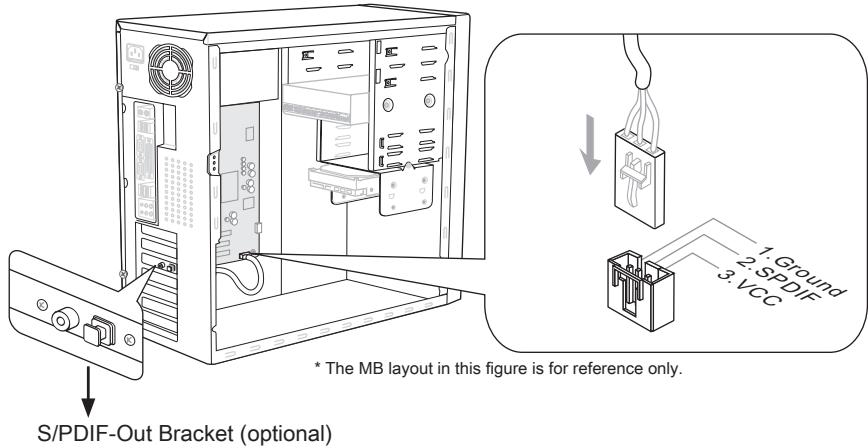
S/PDIF-Out Connector: JSP1
This connector is used to connect S/PDIF (Sony & Philips Digital Interconnect Format) interface for digital audio transmission.
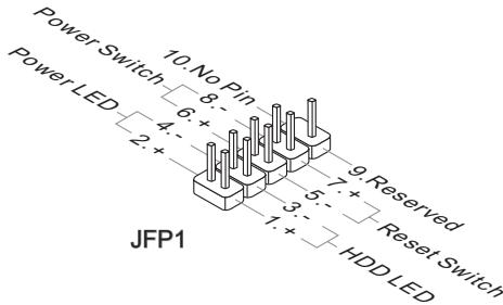
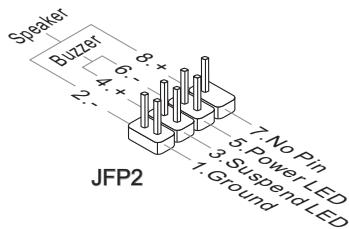
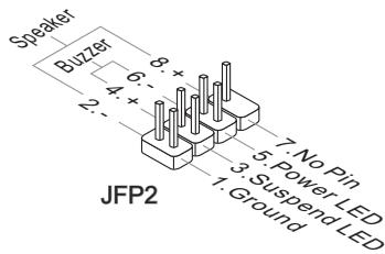
Front Panel Connectors: JFP1, JFP2
These connectors are for electrical connection to the front panel switches and LEDs. The JFP1 is compliant with Intel® Front Panel I/O Connectivity Design Guide.
TPM Module connector: JTPM1
This connector connects to a TPM (Trusted Platform Module) module (optional). Please refer to the TPM security platform manual for more details and usages.
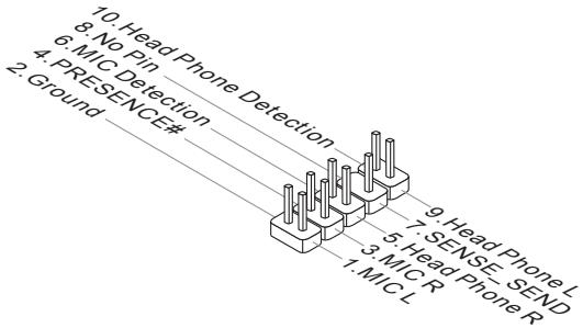
Front Panel Audio Connector: JAUD1
This connector allows you to connect the front panel audio and is compliant with Intel® Front Panel I/O Connectivity Design Guide.
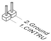
Chassis Intrusion Connector: JCI1
This connector connects to the chassis intrusion switch cable. If the chassis is opened, the chassis intrusion mechanism will be activated. The system will record this status and show a warning message on the screen. To clear the warning, you must enter the BIOS utility and clear the record.
Jumpers
Clear CMOS Jumper: JBAT1
There is a CMOS RAM on board with an external battery power supply to preserve the system configuration data. With the CMOS RAM, the system can automatically boot OS every time it is turned on. If you want to clear the system configuration, set the jumper to clear data.

JBAT1

Keep Data

Clear Data
Important
You can clear CMOS by shorting 2-3 pin while the system is off. Then return to 1-2 pin position. Avoid clearing the CMOS while the system is on; it will damage the mainboard.
Buttons
The mainboard provides the following buttons for you to set the computer's function. This section will explain how to change your mainboard's function through the use of button.
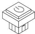
Power Button
This button is used to turn-on or turn-off the system. Press the button to turn-on or turn-off the system.
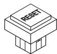
Reset Button
This button is used to reset the system. Press the button to reset the system.
Slots
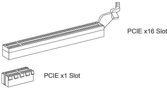
PCIE (Peripheral Component Interconnect Express) Slot
The PCIE slot supports the PCIE interface expansion card.
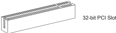
PCI (Peripheral Component Interconnect) Slot
The PCI slot supports LAN card, SCSI card, USB card, and other add-on cards that comply with PCI specifications.
Important
When adding or removing expansion cards, make sure that you unplug the power supply first. Meanwhile, read the documentation for the expansion card to configure any necessary hardware or software settings for the expansion card, such as jumpers, switches or BIOS configuration.
PCI Interrupt Request Routing
The IRQ, acronym of interrupt request line and pronounced I-R-Q, are hardware lines over which devices can send interrupt signals to the microprocessor. The PCI IRQ pins are typically connected to the PCI bus pins as follows:
| Order1 | Order2 | Order3 | Order4 | |
| PCI Slot1 | INT E# | INT F# | INT G# | INT H# |
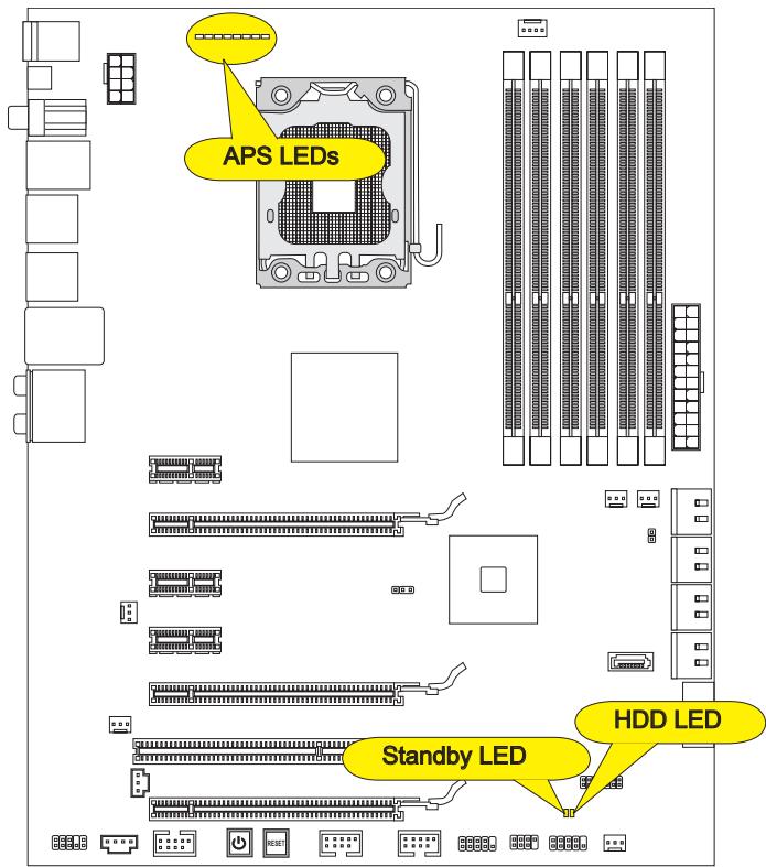
LED Status Indicators
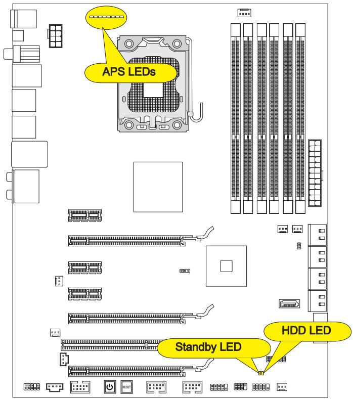
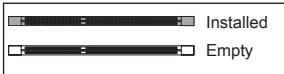
APS LEDs
These APS (Active Phase Switching) LEDs indicate the current CPU power phase mode. Follow the instructions below to read.
:Lights
□:Off
□□□□□□□CPU is in 1 phase power mode.
CPU is in 2 phase power mode.
CPU is in 3 phase power mode.
CPU is in 4 phase power mode.
CPU is in 5 phase power mode.
CPU is in 6 phase power mode.
CPU is in 7 phase power mode.
CPU is in 8 phase power mode.
HDD LED
Lights red when the hard drive is operating.
Standby LED
Lights orange when the system is in standby (S4/S5) status.
BIOS Setup
This chapter provides basic information on the BIOS Setup program and allows you to configure the system for optimum use. You may need to run the Setup program when:
- An error message appears on the screen during the system booting up, and requests you to run BIOS SETUP.
You want to change the default settings for customized features.
Important
- The items under each BIOS category described in this chapter are under continuous update for better system performance. Therefore, the description may be slightly different from the latest BIOS and should be held for reference only.
- Upon boot-up, the 1st line appearing after the memory count is the BIOS version. It is usually in the format:
A7522IMS V5.2 102810 where:
1st digit refers to BIOS maker as A = AMI , W = AWARD , and P = PHOENIX . 2nd - 5th digit refers to the model number.
6th digit refers to the chipset as I = Intel, N = NVIDIA, A = AMD and V = VIA.
7th - 8th digit refers to the customer as MS = all standard customers.
V5.2 refers to the BIOS version.
102810 refers to the date this BIOS was released.
Entering Setup
Power on the computer and the system will start POST (Power On Self Test) process. When the message below appears on the screen, press key to enter Setup.
Press DEL to enter SETUP
If the message disappears before you respond and you still wish to enter Setup, restart the system by turning it OFF and On or pressing the RESET button. You may also restart the system by simultaneously pressing <Ctrl> , <Alt> , and <Delete> keys.
Getting Help
After entering the Setup menu, the first menu you will see is the Main Menu.
Main Menu
The main menu lists the setup functions you can make changes to. You can use the arrow keys (↑↓) to select the item. The on-line description of the highlighted setup function is displayed at the bottom of the screen.
Sub-Menu
If you find a right pointer symbol appears to the left of certain fields that means a submenu can be launched from this field. A sub-menu contains additional options for a field parameter. You can use arrow keys (↑↓) to highlight the field and press
The BIOS setup program provides a General Help screen. You can call up this screen from any menu by simply pressing <F1> . The Help screen lists the appropriate keys to use and the possible selections for the highlighted item. Press <Esc> to exit the Help screen.
The Main Menu
Once you enter BIOS CMOS Setup Utility, the Main Menu will appear on the screen. The Main Menu allows you to select from the setup functions and two exit choices. Use arrow keys to select among the items and press
| Standard CMOS Features | Cell Menu |
| Advanced BIOS Features | M-Flash |
| Integrated Peripherals | Overclocking Profile |
| Power Management Setup | Load Fail-Safe Defaults |
| H/W Monitor | Load Optimized Defaults |
| Green Power | Save & Exit Setup |
| BIOS Setting Password | Exit Without Saving |
Standard CMOS Features
Use this menu for basic system configurations, such as time, date etc.
Advanced BIOS Features
Use this menu to setup the items of special enhanced features.
Integrated Peripherals
Use this menu to specify your settings for integrated peripherals.
Power Management Setup
Use this menu to specify your settings for power management.
H/W Monitor
This entry shows your PC health status.
Green Power
Use this menu to specify the power phase.
BIOS Setting Password
Use this menu to set the password for BIOS.
Cell Menu
Use this menu to specify your settings for frequency/voltage control and overclocking.
M-Flash
Use this menu to read/ flash the BIOS from storage drive (FAT/ FAT32 format only).
Overclocking Profile
Use this menu to save/ load your settings to/ from CMOS for BIOS.
Load Fail-Safe Defaults
Use this menu to load the default values set by the BIOS vendor for stable system performance.
Load Optimized Defaults
Use this menu to load the default values set by the mainboard manufacturer specifically for optimal performance of the mainboard.
Save & Exit Setup
Save changes to CMOS and exit setup.
Exit Without Saving
Abandon all changes and exit setup.
When entering the BIOS Setup utility, follow the processes below for general use.
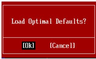
- Load Optimized Defaults: Use control keys ( ) to highlight the Load Optimized Defaults field and press < Enter>, a message as below appears:
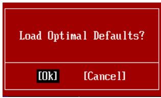
Select [Ok] and press Enter to load the default settings for optimal system performance.
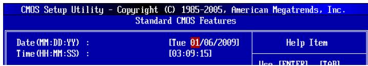
- Setup Date/ Time : Select the Standard CMOS Features and press
to enter the Standard CMOS Features-menu. Adjust the Date, Time fields.
- Save & Exit Setup: Use control keys ( ) to highlight the Save & Exit Setup field and press
, a message as below appears:

Select [Ok] and press Enter to save the configurations and exit BIOS Setup utility.
Important
The configuration above are for general use only. If you need the detailed settings of BIOS, please see the complete version of English manual on MSI website.
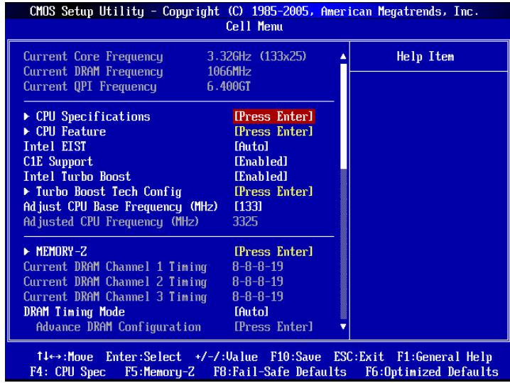
- Cell Menu Introduction : This menu is for advanced user who want to overclock the mainboard.
Important
Change these settings only if you are familiar with the chipset.
Current CPU / DRAM / QPI Frequency
These items show the current frequencies of CPU, Memory and QPI. Read-only.
CPU Specifications
Press
CPU Technology Support
Press
CPU Feature
Press
Intel EIST
The Enhanced Intel SpeedStep technology allows you to set the performance level of the microprocessor. This field will appear after you installed the CPU which supports speedstep technology.
Intel C-STATE
C-state is a power management state that significantly reduces the power of the processor during idle. This field will appear after you installed the CPU which supports c-state technology.
C State package limit setting
This field allows you to select a C-state level. We recommend that you leave this setting to Auto.
C1E Support
To enable this item to read the CPU power consumption while idle. Not all processors support Enhanced Halt state (C1E).
Overspeed Protection
Overspeed Protection function can monitor the current CPU draws as well as its power consumption. If it exceeds a certain level, the processor automatically reduces its clock speed. If you want to overclock your CPU, set it to [Disabled].
Hyper-Threading Function
The processor uses Hyper-Threading technology to increase transaction rates and reduces end-user response times. The technology treats the two cores inside the processor as two logical processors that can execute instructions simultaneously. In this way, the system performance is highly improved. If you disable the function, the processor will use only one core to execute the instructions. Please disable this item if your operating system doesn't support HT Function, or unreliability and instability may occur.
Important
Enabling the functionality of Hyper-Threading Technology for your computer system requires ALL of the following platform Components:
- CPU: An Intel® Processor with HT Technology;
- Chipset: An Intel® Chipset that supports HT Technology;
- BIOS: A BIOS that supports HT Technology and has it enabled;
- OS: An operating system that supports HT Technology.
For more information on Hyper-threading Technology, go to:
http://www.intel.com/products/ht/hyperthreading_more.htm
Execute Bit Support
Intel's Execute Disable Bit functionality can prevent certain classes of malicious "buffer overflow" attacks when combined with a supporting operating system. This functionality allows the processor to classify areas in memory by where application code can execute and where it cannot. When a malicious worm attempts to insert code in the buffer, the processor disables code execution, preventing damage or worm propagation.
Set Limit CPUID MaxVal to 3
The Max CPUID Value Limit is designed limit the listed speed of the processor to older operating systems.
Intel Virtualization Tech
This item is used to enable/disable the Intel Virtualization technology. For further information please refer to Intel's official website.
Intel VT-d
This item is used to enable/disable the Intel Virtualization Technology for Directed I/O (VT-d). For further information please refer to Intel's official website.
Intel EIST
The Enhanced Intel SpeedStep technology allows you to set the performance level of the microprocessor whether the computer is running on battery or AC power. This field will appear after you installed the CPU which supports speedstep technology.
C1E Support
To enable this item to read the CPU power consumption while idle. Not all processors support Enhanced Halt state (C1E).
Intel Turbo Boost
This item will appear when you install a CPU with Intel Turbo Boost technology. This item is used to enable/ disable Intel Turbo Boost technology. It can scale processor frequency higher dynamically when applications demand more performance and TDP headroom exists. It also can deliver seamless power scalability (Dynamically scale up, Speed-Step Down). It is the Intel newly technology within i7 CPU.
Turbo Boost Tech Config
Press
Turbo Ratio Limit Program
This item is used to enable/ disable the turbo ratio limit program. Setting to [Enable] activates the following fields.
1/2/3/4/5/6-Core Ratio Limit
These items allow you to select the CPU core ratio limit.
TDC Limit Override
Setting to [Enable] activates the TDC Limit value field, and use the TDC Limit value field to set the CPU TDC value.
TDC Limit value (A)
This item allows you to select the CPU TDC value (ampere).
TDP Limit Override
Setting to [Enable] activates the TDP Limit value field, and use the TDP Limit value field to set the CPU TDP value.
TDP Limit value (W)
This item allows you to select the CPU TDP value (watt).
Adjust CPU Base Frequency (MHz)
This item allows you to set the CPU Base clock (in MHz). You may overclock the CPU by adjusting this value. Please note the overclocking behavior is not guaranteed.
Adjusted CPU Frequency (MHz)
It shows the adjusted CPU frequency. Read-only.
MEMORY-Z
Press
DIMM1~6 Memory SPD Information
Press
Current DRAM Channel Timing
It shows the installed DRAM Timing. Read-only.
DRAM Timing Mode
Select whether DRAM timing is controlled by the SPD (Serial Presence Detect) EEPROM on the DRAM module. Setting to [Auto] enables DRAM timings and the following "Advance DRAM Configuration" sub-menu to be determined by BIOS based on the configurations on the SPD. Selecting [Manual] allows users to configure the DRAM timings and the following related "Advance DRAM Configuration" sub-menu manually.
Advance DRAM Configuration
Press
CH1/ CH2/ CH3 1T/2T Memory Timing
This item controls the SDRAM command rate. Select [1N] makes SDRAM signal controller to run at 1N (N=clock cycles) rate. Selecting [2N] makes SDRAM signal controller run at 2N rate.
CH1/ CH2/ CH3 CAS Latency (CL)
This controls the CAS latency, which determines the timing delay (in clock cycles) before SDRAM starts a read command after receiving it.
CH1/ CH2/ CH3 tRCD
When DRAM is refreshed, both rows and columns are addressed separately. This setup item allows you to determine the timing of the transition from RAS (row address strobe) to CAS (column address strobe). The less the clock cycles, the faster the DRAM performance.
CH1/ CH2/ CH3 tRP
This setting controls the number of cycles for Row Address Strobe (RAS) to be allowed to precharge. If insufficient time is allowed for the RAS to accumulate its charge before DRAM refresh, refresh may be incomplete and DRAM may fail to retain data. This item applies only when synchronous DRAM is installed in the system.
CH1/ CH2/ CH3 tRAS
This setting determines the time RAS takes to read from and write to memory cell.
CH1/ CH2/ CH3 tRFC
This setting determines the time RFC takes to read from and write to a memory cell.
CH1/ CH2/ CH3 tWR
Minimum time interval between end of write data burst and the start of a precharge command. Allows sense amplifiers to restore data to cells.
CH1/ CH2/ CH3 tWTR
Minimum time interval between the end of write data burst and the start of a column-read command. It allows I/O gating to overdrive sense amplifiers before read command starts.
CH1/ CH2/ CH3 tRRD
Specifies the active-to-active delay of different banks.
CH1/ CH2/ CH3 tRTP
Time interval between a read and a precharge command.
CH1/ CH2/ CH3 tFAW
This item is used to set the tFAW timing.
- Current CH1/ CH2/ CH3 tdrRdTd/ tddRdTd/ tsrRdTWr/ tdrRdTWr/ tddRdTWr/ tsrWrTDr/ tddWrTWr/ tsrRDTRd/ tsrWrTWr
These item show the advanced DRAM timings.
Channel 1/ Channel2 Advanced Memory Setting
Setting to [Auto] enables the advance memory timing automatically to be determined by BIOS. Setting to [Manual] allows you to set the following advanced memory timings.
Memory Ratio
This item allows you to set the memory multiplier.
Adjusted DRAM Frequency (MHz)
It shows the adjusted DRAM frequency. Read-only.
Uncore Ratio
This item allows you to set the uncore multiplier.
Adjusted Uncore Frequency (MHz)
It shows the adjusted uncore frequency. Read-only.
QPI Configuration
Press
QPI Links Speed
This item allows you to select the QPI links speed type.
QPI Frequency
This item allows you to select the QPI frequency.
ClockGen Tuner
Press
CPU Amplitude Control/PCI Express Amplitude Control
These items are used to select the CPU/PCI Express clock amplitude.
CPU CLK Skew/MCH CLK Skew
These items are used to select the CPU/ MCH chipset clock skew. They can help CPU to reach the higher overclocking performance.
Adjust PCI Frequency (MHz)
This field allows you to select the PCI frequency (in MHz).
Adjust PCI-E Frequency (MHz)
This field allows you to select the PCIE frequency (in MHz).
Auto Disable PCI/PCI-E Frequency
When set to [Enabled], the system will remove (turn off) clocks from empty PCI and PCI-E slots to minimize the electromagnetic interference (EMI).
- CPU Voltage (V)/ CPU PLL Voltage (V)/ QPI Voltage (V)/ DRAM Voltage (V)/ DDR_VREF_CA_A (V)/ DDR_VREF_CA_B (V)/ DDR_VREF_CA_C (V)/ DDR_VREF_DQ_A (V)/ DDR_VREF_DQ_B (V)/ DDR_VREF_DQ_C (V)/ IOH Voltage (V)/ ICH Voltage (V)
These items are used to adjust the voltage of CPU, Memory and chipset.
Spread Spectrum
When the mainboard's clock generator pulses, the extreme values (spikes) of the pulses create EMI (Electromagnetic Interference). The Spread Spectrum function reduces the EMI generated by modulating the pulses so that the spikes of the pulses are reduced to flatter curves.
Important
- If you do not have any EMI problem, leave the setting at [Disabled] for optimal system stability and performance. But if you are plagued by EMI, select the value of Spread Spectrum for EMI reduction.
- The greater the Spread Spectrum value is, the greater the EMI is reduced, and the system will become less stable. For the most suitable Spread Spectrum value, please consult your local EMI regulation.
- Remember to disable Spread Spectrum if you are overclocking because even a slight jitter can introduce a temporary boost in clock speed which may just cause your overclocked processor to lock up.
Important
Failed Overclocking Resolution
This mainboard supports overclocking greatly. However, please make sure your peripherals and components are bearable for some special settings. Any operation that exceeds product specification is not recommended. Any risk or damage resulting from improper operation will not be under our product warranty.
Two ways to save your system from failed overclocking...
Reboot
Press the Power button to reboot the system three times. Please note that, to avoid electric current to affect other devices or components, we suggest an interval of more than 10 seconds among the reboot actions.

At the fourth reboot, BIOS will determine that the previous overclocking is failed and restore the default settings automatically. Please press any key to boot the system normally when the following message appears on screen.
Warning !!! The previous overclocking had failed, and system will restore its defaults setting, Press any key to continue......
Clear CMOS
Please refer to "how to clear CMOS data" section for more information about how to clear CMOS data.
Software Information
Take out the Driver/Utility DVD that is included in the mainboard package, and place it into the DVD-ROM drive. The installation will auto-run, simply click the driver or utility and follow the pop-up screen to complete the installation. The Driver/Utility DVD contains the:
- Driver menu : The Driver menu shows the available drivers. Install the driver by your desire and to activate the device.
- Utility menu : The Utility menu shows the software applications that the mainboard supports.
Important
Please visit the MSI website to get the latest drivers and BIOS for better system performance.

Deutsch
X58A-GD45
Serie
Spezifikationen
Prozessoren
Frontpanel Anschlüsse: JFP1, JFP2
Press DEL to enter SETUP
| Standard CMOS Features | Cell Menu |
| Advanced BIOS Features | M-Flash |
| Integrated Peripherals | Overclocking Profile |
| Power Management Setup | Load Fail-Safe Defaults |
| H/W Monitor | Load Optimized Defaults |
| Green Power | Save & Exit Setup |
| BIOS Setting Password | Exit Without Saving |
Overclocking Profile
CPU Technology Support
http://www.intel.com/products/ht/hyperthreading_more.htm
Execute Bit Support
Intel Virtualization Tech
Adjust CPU Base Frequency (MHz)
Adjusted CPU Frequency (MHz)
Current DRAM Channel Timing
Adjusted DRAM Frequency (MHz)
Adjusted Uncore Frequency (MHz)
Adjust PCI Frequency (MHz)
Adjust PCI-E Frequency (MHz)
Warning !!! The previous overclocking had failed, and system will restore its defaults setting, Press any key to continue......
Clear CMOS
Emplacement PCIE (Peripheral Component Interconnect Express)
Emplacement PCI (Peripheral Component Interconnect)
Press DEL to enter SETUP
| Standard CMOS Features | Cell Menu |
| Advanced BIOS Features | M-Flash |
| Integrated Peripherals | Overclocking Profile |
| Power Management Setup | Load Fail-Safe Defaults |
| H/W Monitor | Load Optimized Defaults |
| Green Power | Save & Exit Setup |
| BIOS Setting Password | Exit Without Saving |
Standard CMOS Features (Fonctions CMOS standard)
Current CPU / DRAM / QPI Frequency
CPU Technology Support
http://www.intel.com/products/ht/hyperthreading_more.htm
Intel Virtualization Tech
Adjust CPU Base Frequency (MHz)
Adjusted CPU Frequency (MHz)
Warning !!! The previous overclocking had failed, and system will restore its defaults setting,
Press any key to continue.....
Effacer CMOS
XeTbnTrepyoBnHKn BnBnETcN nHkATOP 1 KOHT.
YctaHOBka npoceccopa n BENTNJIATOPA
Bo n36ekahne neperpeba npa pabote o6ra3atebho yctahOBHTe BHTnIaTOp npoecccopa. Ondobpemehno, yTO6bI yJyUHNTb TeNIOOTBOD, y6eINTEcB TOM, yTO HAnecEHN CNoI TeNlnonpoBOdauei NaCTbHa npOceCCope nepeD yCTAHOBKOB BeHTnIaTopa.
CneyuTe daHbIM yka3aHnM dIy npabInbHO yCTaHOKn. HenpaBnBnaY cTaHOBA npBeDeT K NOBpeKdEHHIO pOceccopa n CNTeMHo INaTbI.
- Notarynte 3a pbyar kpenneHna.
- Pa3bem npoceccopa 3akpbIT pnaCTNKOBON KpbIshKoN, KOtopa 3aunuzaet KOHTaKTbI pa3bema OT nobpejdeHNI. Pn OTCyTCTBNI npoceccopa, Heo6xOdmo Bcerda 3akpbIBaTb pa3bem pnaCTNKOBON KpbIshKoN dJr 3aunuTbI erO KOHTaKTOB. CnIMnte KpbIshKy (kak noka3bIbaet cTpeJka).
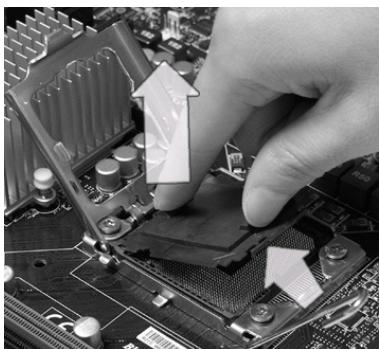
- Пдимпе рьuar n OTKpoIte MeTaalmYeCKyU KpbIuKу ДЯ yctahOBkn npOceccopa.
- Y6eDnBwncb B npaBnJIbHoI opneHTaun npoceccopa, nOJoxNte npoceccop B pa3beM. O6paTnte BHImaHne, yTO BbEMKn Ha npoceccope DOJXhbl COOTBeTCTBOBaTb BbICTyNam Ha npoceccopHom pa3beMe.
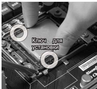
- Bn3yaJIbHOpOBepbTe npabINbHocTb yCTaHOBKn npOeCCopa B pa3beM. Ecnn npoecCop yCTaHOBNeH He npaBnIbHO, TO BBInbTe npOeCCop n nepeycTaHOBIne.
- AkkypaTHO onyctnte pbUar Ha KpbIuKy MexaHn3Ma KpeNJIeHn I 3aФИKcnpyTe erO.ДЯ PhIKCaUNI pyUra B MEXaHn3Me KpeNJIeHn IpeDycmOTpeh CneUaJIbHbI BBICTyI.
- Onyctnte MaTaJIHnueckyo KpbIshky MexaHn3Ma KpeJIeHnI.
- CoBmecntte OTBepCTnCnCTEmHOI PnAbl C 3aueKamn KpePJIeHnBEHTNJTOpa.PnIXMNTe paDnATOp C BeHTNJTOpOM K npOceCCopy INpocLeNDte, YTO6bI YeTBIpE 3aueKIN BOJIN B OTBepCTnCnCTEmHOI PnAbl.
BhimaHue
-
Ipeed BkIoueHneM CNTeMbI yBeIuTeCb, YTO BeHTnIaTOp npaBnIbHO yCTaHOBnEh.
-Bo n36ekanHe noBpeKdEnH He npKacaiTeCb K KOHTaKtAm CokeTa npOceccopa. -
Haxmnte Ha yetbipe 3auekeni n 3akpenITE BENTnIaTOp.
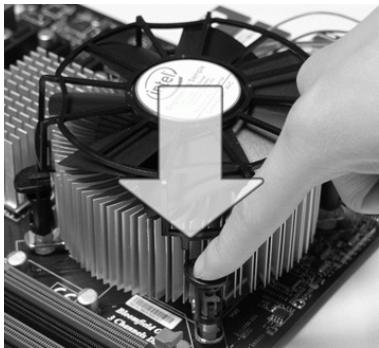
10.Перевернite систмунлалуи ybeintecb,чTo 3aшелкн haedжHo ydeprxnbAOT BeHTnIaTOp.
UcTaHOBKa MoDyJIe NAmrTn
- Moулп памят ИмеOTToьКО OndHy npope3bВcepeINHe.Moуль BoДeТВ pa3bemToьКОпрnpaBnIbHOnOpneHTaUIN.
- BCTaBbTe Moynb DIMM cnot B BeptnKaIbHOM HappaJIeHm. 3aTeM haxMtte Ha Hero, yTo6bl 3oNoJeHbE KoHTaKtbl rny60KO norpTy3nIncb B DIMM cnot. Ecnn Moynb NaMaTn BCTaBJIeH npaBnIbHO, To pNaCTNkoBbIE 3aUeJIkN Ha o6Ox KOHcX 3aKpOHcR abTomAtuYeCKn.
- BpyuHny u6eIntecb, yTo moUyIb 3aKpeIenB CnOte DIMM 3aUeJIkamn c o6eHX CTOpOH.
BHMNAHNE
30notbke KOHTaKtbl eDBA BnHbI,ecN MOnyN nAmrTn npaBnBHO pa3MeueHbIBDIMM cnote.
Pa3bem NHTaHn
24-KoHTaKTbI pa3bem nITaHnA TX: JPWR1
3TOT pa3bem NO3BOJRAET NOKNIHOHTb 24-KoHTaKTbH KOHKeTOp nHTAHN ATX. IJIra erO noKJIIOUeHn y6eIInTeCb, YTO KOHKeTOp N KOHTaKTbI pa3bema npabUNbHO copHeHTPOBaHbI. 3aTeM NIOTHO BCTaBbTe erO B pa3bem Ha CNTcEMHO nIATE.
BbI TAKKe MoKTe NcNoJIb3OBAtB 20-KoHTaKTHbIy ATX 6nok nTahnI. PpN IcNoJIb3OBAHmN 20-KoHTaKTHOro pa3bema, NoJckJIouaYte erO BdoJI KoHTaKToB 1 n 13.
8-KoHTaKThbI pa3bem nHTaHnA TX: JPWR3
3Tn pa3bembl nCnOlb3yIOTc dIJI o6ecneueHn IITaHn Ipoceccopob 12V.
3aHnaHaHeIb
KoHneKToPbI nepeDHeN paHeN: JFP1, JFP2
ÖTN KOHNÉKTopbI NcONJb3yOToTcДЯ NpOKnIQUeHnKHOPOK INHdNkAToPoB, paCNoLoXeHHbIX Ha nepeDnei naHenn KOpnyca. KoHNéKTop JFP1 coOTBeTCTByeT pyKOboODCTBy Intel® Front Panel I/O Connectivity Design.

Pa3bEm TPM MoynjA: JTPM1
Cnot PCIE (Peripheral Component Interconnect Express)
Cnot PCIE noDepknaeT KapbI paCSnpeHn INTepeCa PCIE.
PCIE x16 cnot
PCIEx1cnot
Cnot PCI (Peripheral Component Interconnect)
CnotPCI no3Bolraet yctahOBnTB KapbI LAN, SCSI, USB nDpyrme doonHnTeNbHbIe KapbI paacupeHn, KOtOpblc COOTBeTCTByOT cneunkaunn PCI.
32-bitPCIcnot
BHHMaHHe
Ipepe yctahOBKO uINu IN3BneueHem KapT pacuHpeHn y6eNTecb, yTO Ka6enb nITAHnO TKNUChEN OT 3NeKtpNuecko cTeN. IpoHTte DokyMeNTaCuH No KAPTy pacuHpeHn N BblONHIne Heo6xOdHMble annapaTHbE uIN npOrpaMhBe yCTAHOBKn dJaHHo INaTbI, TaKne KaK nepeMbUcKn, nepeKluOaTeIN uIN KOHNpyauCIO BIOS.
CBeTOBbIe INHdNkAToPbI
ИндикаТоры APS (APS LEDs)
3TN INdikatopbl APS (Active Phase Switching) noka3bIbaHT pekIM pa60tbl NCTOCHNA pNTaHnI npoecccopa. INΦopMaunO coCToHNm INdikatopOB npuBeDeHa B Tablne.
■:BKJIIOUeyE □:BbIKJIIOUeyEH
CPU nCnoIb3yeT 1 pa3y nIITaHnI.
CPU nCnoIb3yeT 2 pa3bl nHTaHn.
CPU nCnoB3yeT 3 pa3bI nHTaHn.
CPU nCnoB3yeT 4 pa3bI nHTaHnA.
CPU nCnoJb3yeT 5 pa3 nIITAHnI.
CPU nCnoJb3yeT 6 pa3 nIITaHnI.
CPU nCnoJb3yeT 7 pa3 nIITaHnI.
CPU nCnoJb3yET 8 pa3 nItaHna.
INHdkaTOp JKcKTOO DnCKa (HDD LED)
Tognt KpaChbim npa6oTe JeCTkoRIO nIcKa.
Индikatop сяшero ржима (Standby LED)
Topn opaHKeBbIM npn cnIaIe m pexIme cInTeMbI (S4/S5).
Hactpoika BIOS
B 3toi rnaBe npnboaTcO cHOBbIe CBeEHHa O pexmHe hactpoKn BIOS (BIOS SETUP), KOtOpbI nO3BOJAEr YCTaHOBHT oNTMmaIbHyIO KOHpIpyaUHO CnCTeMbI. 3TO T pexm MoKeT NOTpe6oBaTcBcA B CneDyUOx CNyuaX:
Bo Bpem3aarp3kn cncTeMbI NOBbIeTcOo6ueHne 06 OuN6Ke C tpe6obAHnEM 3anyctntb BIOS SETUP.
B cnyuae Heo6xoJIMOCtN 3aMeHnTb 3aBOcKne HacTpOKn Ha co6CTBeHHbIe.
BhimhaHue
Press DEL to enter SETUP
(HaXmnte DEL nIy BxoJaB SETUP)
Ecni coo6eHHe nCue3I, a BbI He ycneI hXaKbNHy, nepe3anyctnte cncTeMy, BbIKNoUHB u ChOBA BKnIOuHB nITaHHe, IIN Hxab KhoNky RESET. MoXHo, TaKKe, nepe3anyctntb CnCTeMy, Hxab OndHOBpeMeHHo KnaBUns
Pexim HactpoiK
BoiIaBpeXIMHacTpoiKn, BbIcpa3y yBvIaNTe TlaBHOe MeHIO.
Main Menu (Главhoe мени)
Главhoe MeHIO codepxNT cNICOK HAcTpoE, KOTOpBIE bbl MoKTe N3MeHnTb.ДЯ BbIbopa moXHO nCNoJIb3OBAtB kNaBnSiOn CO tpeKNaMn (↑↓). CnpabKa O bblpaHHOH NaCTpoJKe OTObpaJaTaC T B HIXHe Yactn 3KpHaHa.
Повменно
EcnBbObHApYKNTe,TO CnBea OT nyHKTa MeHIO NMeETc 3HaK npaBOr Oyka3aTeJRA 3To O3NaHaeT HAnuHne NOmEHIO, CoepXaUero DOnONHtEnbHbe HAcTPOiKN KOTOpBle MOxHcCdeIaTb B 3Tom NyHKTe. NcNoIb3yIte ynpabJIouIe KlaBnSi (↑ ↓) dIra Bbl6op a, a 3aTeM haxMtTe
POnpo6Na cnpaBka
B pexime hactpoikn BIOS nmeetcra Bo3MOxHocTh npolyehnnpo6ho cnpaBkn. Ee moKHO BbI3BaTbN 3JIIO6OTo MeHIO npocTbIM HaxKaTneM
The Main Menu (Главhoe мени)
Pn Bxode B pexkim HacptpoKBIOS Ha 3kpahe OTo6paxaetcra TnaBHOe MeHIO. TnaBHOe MeHIO N03BOJRAET Bb6paTb FyHKmN HAcTPOKn N IMeET Dba BapnAHTa BbIXoJa. IJIpeMeueHnI IO NyHKtAm NCNoJIb3yOTcR KNaBUn Co cTrpeKamN
| Standard CMOS Features | Cell Menu |
| Advanced BIOS Features | M-Flash |
| Integrated Peripherals | Overclocking Profile |
| Power Management Setup | Load Fail-Safe Defaults |
| H/W Monitor | Load Optimized Defaults |
| Green Power | Save & Exit Setup |
| BIOS Setting Password | Exit Without Saving |
Standard CMOS Features (CTaHdapTHbIe yHKuIN CMOS)
3To MeHIO N03BOJnEYcTaHOBtB OCHOBHbIe NapaMeTpbl KOHfNpyaCINN CnCTEmbl (daTy, Bpemr n T.I.).
Advanced BIOS Features (Дононтелови phкии BIOS)
3To MeHIO nCNoB3yeTcra nIa HacTpoNk CneuaNbHbXf yHKuBIOS.
Integrated Peripherals (BcTpoeHbIe nepupepiHbIe yctpoicta)
3To MeHIO NcNoJIb3yETcA dIa HAcTpoiKn IapaMeTPOB BCTpoeHHbIX nepuΦepnHbIX yCTpoiCTB.
Power Management Setup (Hactpojka ynpablenia nntaHneM)
3To MeHIO no3B0JraET 3aDaTb npaMeTpbl ynpaBHeHnI NITaHnEM CnCTeMbI.
H/W Monitor (MonHTop annapatnoi qactn)
3TOT nyHKT OTo6paKaJaTe COCTOaHne annapaTHou qactn PIK.
Green Power
3To MeHIO NcIOnb3yETcI dIaHa3HaueHnpeXIMa PITaHnI.
BIOS Setting Password (Парол дocуна К несторкam BIOS)
3To MeHIO NcNOJIb3yETcra, YTO6bl 3aDaTb npOJIb.
Cell Menu (MeHIO y3Ja "Cell")
3TO MeHIO NO3BOJIAReT ynpabJIaTb TaKToBbIMu YacTOTAMN IN HaprJKeHnMn npn pa3roHe CNTEmbl.
M-Flash
Исплььетсдячтени/пршовBIOSсВишиноюнakонителя(TолькоFAT/FAT32).
Overclocking Profile
IcnoIb3yETcIa coxpanenH/ 3arpy3kn HacTpoek B/ n3 CMOS namrtn BIOS.
Load Fail-Safe Defaults
3To MeHIO nCnOJIb3yETcI dIa 3arpy3Kn 3NaueHnBIOS, yCTaHOBJIeHHbIX npOn3BOIDTeIeM dIra CTA6NJbHOI CNCTeMbI.
Load Optimized Defaults (YctaHOBnTb ONTMaJIbHbHe NaCTpoKn)
3To MeHIO NcNoJIb3yeTcI dIg 3aRpy3Kn HAcTpoE KN3rOToBtTeJ IJr ONTImaJIbHOI npOn3BOUInTeJIbHOCTn CnCTeMHoI PJIaTbI.
Save & Exit Setup (BbIXoD c coxpaHHeM hAcTpoE)
3aIncb nImMeHenn B CMOS n BbIXoN n3 peKIma HacTpoKn.
Exit Without Saving (BbIXoN 6e3 coxpaHEnn)
OTmeHa BcEx N3MeHeHn N BbIXoD n3 peKIma HaCTpOKn.
B obuem clyuae, haxoJcB b pexnme hactpoKBIOS, pekomeHnyetc BbINOHNITb cIeDyUOUIne deICTBIA.
- Load Optimized Defaults: KnaBnIaMn ynpaBJIeHnra ( ) BbIbepnte npHKT Load Optimized Defaults n haxmTe
, noRbTc sCneDyUoee coo6uHHe:
HaxmTe [Ok], yTo6bI 3arpy3nTb HacTpoKn IOn yMOJIuaHInIO IJRA ONTImaJIbHOI npOn3BOAnTeJIbHOCTN CnCTeMbI.
HaxmTe [Ok], yTo6bI coXpaHnTb KoHpyrugaIu I BbItn n3 BIOS Setup.
BhimhaHue
PnBVeDHHa BbIe KOHpNrgpaunnoJIOXoOIT nJor oBsqero npMmeHnE. EcnJxBe Bam TpebYOTcB 60Je ToKHe NaCTpoiKnBIOS, oBaPATtec b K aHrnnckoB vepnnpykoBDCTBa Ha Be6-caTe MSl.
Current CPU / DRAM / QPI Frequency
3TN nyHKtbI noka3bIbaIOT Tekyu yO yactOTy CPU n ckopocTb namrtnn QPI. TOnbko dIryteHn.
CPU Specifications
Haxmnte
CPU Technology Support
Haxmte
CPU Feature
HaxmTe
Intel EIST
TexHONorIg Enhanced Intel SpeedStep no3B0JraT yCTaHOBt b ypoBeHb npOn3BOiNTeNbHocTn MkPonpOceccopa. 3ToT nyHKT nOBnErc TcNoCte yCTaHOBKn npOceccopa, KOTOpB IOndepKnaBaET TexHONorIO SpeedStep.
Intel C-STATE
C-state - 3TO texhONoru ynpablennnaTaNHeM, npk KTHBaunK KOtopo3NaHTeJIbHO naaet 3Nepro nOtpbeLHeHne npoceccopa B cPAnE m pexnme. 3TOT nyHKT DocTyneH ToIbKO npn NcNoB3OBaHm CPU c noDdepKko TexhONoru Cstate.
C State package limit setting
3TOT nyHKT NO3BOJAEr BbI6paTb ypoBeHb C-state. PekomeHdyETcra yctaHOBnTb 3TOT nyHKT B Auto.
C1E Support
BkIouHte 3OT nyHKT dIy CHNKeHn 3HeprOnotpe6JIeHn CPU, KOrda OH he pa6oTaET. He BCE npOeCCopbI noDdepKmBAOT Enhanced Halt state (C1E).
Overspeed Protection
Функця Overspeed Protection oTo6paxaet notok BbIuHcIeHn CPU n er0 3hepronotpe6IeHne. Ecn OHO npBeBicNT onpeJeIeHHybl ypoBeHb, To npoceccop abTomatueckn noHn3HT TAKTOByo cactOty. Ecn Bbl co6npaTecb pa3roHrTB CPU, To yctahOBITE 3TOT napaMeTp B [Disabled].
Hyper-Threadsing Function
Ipoceccop nCnoB3yET texHOnIgNIO Hyper-Threading Iny ByeNueHn npOn3BOUInTeNbHocTn. 3Ta texHOnIgNIA No3BOJAE Tbym HabOpam perncTPOB B npOeCCope nCnoHNrTB NcHCTpyKcIM OndOBpeMHNO. 3To yBeNnuBaet npOn3BOUInTeNbHocTb CnCTembl. PnB bIKNUeHn 3ToI yHKm, npOceccop nCnoHReT NcHCTpyKcIM c NOMoCbIO OndHO rApoba rPeNCtPOB. BbIKNUOHTe 3TO npHKT, ecn OnepauNoHHa CnCTema BaWero KOMMbIoTepa He npDdepKNaBaet fynKcIMHO HT, B npOTNBHom Cnyae 3TO MoKeT pINBeCTn K HectaBnHocTn.
BhimhaHne
Дпя paBOTocno6bOCTn TexHONOrn Hyper-Threading, Tpe6yETcra HAnuYe Bcex HIXKeCNeDyUOnX KOMNoHErTOB:
http://www.intel.com/products/ht/hyperthreading_more.htm
Execute Bit Support
IcnoB3oBaHne TexHONorN Execute Disable Bit Intel no3bOJraTb y3BMocTeB B3bBAeMbIX BpeHOChbIMn IpORpAMMaM NkCnJIpyUOUMM Ou6Kn Tnpa "buffer overflow",ecn3TaTexHONOrN NOdepXNBaETcR OepaOnHOcCTemO. OHa No3BOJraTn PPOCECPy pa3deJIb 30hB bPamrN B COOTBcTBN C TeM, xpaHITcJ LIN B pAmrN nCNOHReMbI KOD nIN HET. KorDa BpeHOCHa npORpAMMa NOnblTaetcBCTaBnTB KOD B 6byFep, IpOeCCOP 3anPeTNT NcNoJIHeHne KOA, YTO OCTaHOBnT paCNPocTpaHEnHe BpeHOHOCHn IpORpAMMbI.
Set Limit CPUID MaxVal to 3
Параметр Мax CPUID Value Limit npedna3nauhen Ддя орагиени динны иdentидационною Homepa npoceccopa nepedabaemoro B onepaquohnyocntemy.
Intel Virtualization Tech
3TOT nyHKT hONb3yeTc IaI BKNIOUeHn/BykNIOUeHn TEXHOJrnn Intel Virtualization. 3a DOnoHNHTeBHOINHOpMaueNe CMOPTNE OΦΦuNaIbHbY Be6caNT Intel.
Intel VT-d
ТOTpyнкИСПОЛБ3уETСДЯВКПUCHENI/ВБКПUCHENITEXHONORINIntel VirtualizationДЯDirected I/O (VT-d).3aДоноНITEьнOHиHΦOPMaUNeCMOTPnTe oФфциальнь Вбсай Intel.
Intel EIST
TexHONorra Enhanced Intel SpeedStep no3B0JareT yCTaHOHTb ypoBeHb npOn3BOUnteHbOCTn MmKpOnpoueccopa. 3TO T nyHKT nO8BJIaTeTc nocIe yCTaHOBKn npOceccopa, KOTOpB I NOdEepKINBaET TexHONorruo SpeedStep.
C1E Support
BkIouHte 3OT nyHKT IJIa CHNKeHnIe HeproTope6IeHnI CPU, KOrda OH He pa6oTaet. He BCE npOeessCopbI noIDepxmbaOT Enhanced Halt state (C1E).
Intel Turbo Boost
3TOT nykHT nOABnIETcA, KOrDa BbY yCTaHOBnI CPU, NOdEprKbBAUoIy I TeXHOLrIO Intel Turbo Boost. 3TOT nyHKT nCOnb3yETcA dNra BKJIOUeHn/ BByKJIIOUeHn TeXHOLrIO Intel Turbo Boost. OH nobblaaet cactoty npouecccopa, KOrDa npIKLaIhIbe nporpamMbI tpe6yI0 6OJIbSei npoi3BOIDntleHoctn i TDP npouecccopa 3TO nO3BOJRAET. 3Ta texHONrna TaKke oBeceuBaet PnabHyO MacuTaBnpyEmoctb 3HEprONOTpe6JIeHn (Dynamically scale up, Speed-Step Down). OH HOBeIIaA TeXHOLrna npouecccopob i7.
> Turbo Boost Tech Config
Haxmnte
Turbo Ratio Limit Program
3TOT nyHKT nCOnNoB3yeTcA JnB KJIIOUeHn/ BbIKIOUeHn npOrpAMMbI turbo ratio limit. YctahOBka B [Enabled] akTINBn3Npyet CneDyOuJe nyHKtbl.
1/2/3/4/5/6-Core Ratio Limit
3Tn NykTBI N03B0JHOT BbIbpaTb JIMNT MHOXHTeJIa RJaCPU.
TDC Limit Override
YctaHOBka B [Enable] akTbU3npye TnyKt TDC Limit value, n no3BoJAEr yCTaHOBtB 3NaueHne TDC CPU.
TDC Limit value (A)
3TOT nyHKT no3BONJET BbI6paTB 3HaueHnra CPU TDC (amnepbI).
TDP Limit Override
YctaHOBka B [Enable] akTbN3npye TnyKt TDP Limit value, n no3BoJareT yCTaHOBtB 3NaueHne TDP CPU.
TDP Limit value (W)
3TOT nyHKT no3BONJe TBb6paTb CPU TDP value (BaTTbl).
Adjust CPU Base Frequency (MHz)
3TOT nyHKT no3BONJET yCTaHOBTb TAKTOBy 0acToTy Base clock CPU (B MfU). IV3meHHe 3TOro napameTp a6eCneuBaet BO3MOXHOCTb pa3roHa CPU. BHImaHHe, BO3MOXHOCTb ycNeuHoro pa3roHa He rapaHTnpyetcra.
Adjusted CPU Frequency (MHz)
3TOT nyHKT noka3bIbaeT KekuIyIO TaKTOByIO aCtOty CPU. TOnbKO dNry TeHnA.
MEMORY-Z
Haxmnte
DIMM1~6 Memory SPD Information
Haxmte
Current DRAM Channel Timing
ТOT nyнт поаьаet усановенhhу DRAM Timing. TolькдячehиЯ.
DRAM Timing Mode
OnpeJeIeT 6ydyt IIN BpeMeHHbIe npaMeTpbl DRAM KOHTpOJInpoBaTcBcAaHHbIMn3 SPD (Serial Presence Detect) EEPROM Ha moJyIe DRAM. Ppi BbIbOpE 3NaueHnra [Auto] BpeMeHHbIe npaMeTpbl DRAM, BkIIOUaY pNHTb MeHIO, nepeuCIneHHbIe HIXKe, yCTaHaBJIbaOTcBIOS B COOTBeTCTBUN C daHHbIMn n3 SPD. Ppi ycTaHOBKe 3NaueHnra [Manual], 3OT nyHKT no3BOJIaRET BpyHyO peyInpoBaTb BpeMeHHbIe npaMeTpbl DRAM DoCTynhble B 3tOM MeHIO.
Advance DRAM Configuration
HaxmTe
CH1/ CH2/ CH3 1T/2T Memory Timing
3TOT nyHKT onpeJeIeT ckOpocb pa60tI naMrtu SDRAM. Bb6op [1N] nepeBOJNT KOHTPOJIeP naMrtu SDRAM B pexm pa60tI 1N (N=clock cycles). Bb6op [2N] nepeBOJNT KOHTPOJIeP naMrtu SDRAM B pexm pa60tI 2N.
CH1/ CH2/ CH3 CAS Latency (CL)
3TOT nyHKT KOHTpOJIpyET BPEM 3aIepKKn CAS, KOTOpoe onpeJeT nepIOd (B TaKtax reHepaTopa) Mekdy nolnyeHnem naMaTbTO SDRAM KOMaHdbI UTeHnra NaHaJlOM ee BbINOJIHeHn.
CH1/ CH2/ CH3 tRCD
Adjust PCI Frequency (MHz)
3TOT nyHKT no3B0JraET yCTaHOBnTB yactoty PCI (B MfU).
Adjust PCI-E Frequency (MHz)
3TOT nyHKT no3BONJET yCTAHOBNTb YACTOTy PCIE (B MfU).
Auto Disable PCI/PCI-E Frequency
Пиустановke 3наченя [Enabled], систema OTКПIOUHT HeINCNOJIb3yemble pa3bEmblamЯгпи nPCI,чTo пив徴ET K ChINJKeHnIO yOpOBN 3ЛeКТРOMaRHTnTHbIX NOMEX (EMI).
- CPU Voltage (V)/ CPU PLL Voltage (V)/ QPI Voltage (V)/ DRAM Voltage (V)/ DDR_VREF_CA_A (V)/ DDR_VREF_CA_B (V)/ DDR_VREF_CA_C (V)/ DDR_VREF_DQ_A (V)/ DDR_VREF_DQ_B (V)/ DDR_VREF_DQ_C (V)/ IOH Voltage (V)/ ICH Voltage (V)
TOTnyHKnno3BOJareperyIINPOBaTB HanpJKeHne CPU, namrtnuYInCeTa.
Spread Spectrum
Tak kak TakTOBbI rHeHApOp CnCTeMHoN IJIaTbI NmNyIbChbI, To erO paBOta BblBaET 3JIeKTPomarHHTbIe nomExn - EMI (Electromagnetic Interference).ФункцЯ Spread Spectrum cHIXKaET 3TN NOMEXn, reHepnpy crJaXeHHble IMnyIbCbl.
BHIMAHWE
- Ecnn y Bac Het npo6blem c nomexamn, octabte 3naeHne [Disabled] (3anpeucho) Дялушew CTa6nIbHOCTN n npOIN3BOJNTeBHOCTN. Ondako, ecnn y Bac BO3HnkaOT 3NeKTPomarHHTbIe nomexn, Bbl6epnte Spread Spectrum dny nx yMeHbSeHnry.
-Чмбльше зачени Spread Spectrum, Tem Нжke 6удет уровьн Зелктомагнг themselves NOMex, HO систema ctaHET MeHee CTaBnIbHoN.Дя Вьбopa похаяцero зачени Spread Spectrum, CBepbTeceb co 3haeHЯMu ypOBHei ZelktpomarHngTHbIX NOMex, yctaHOBNeHHbIX 3aKHOHaTeNbCTBOM. - He 3a6ydbTe 3anpeTntb nCOnb3ObaHne yHKnN Spred Spectrum, cInn Bbl "pa3roHaeTe" cnCTeMHyIO pNaTy. 3To Heo6xOIMo, TaK kAJaKe He6oBbOoi Dpe6e3r CnHAnOB TaKTOBOrO rHePaTopa MoKet npNBecTn K OTKa3y "pa3orHaHHoro" npouceccopa.
BhimhaHue
BocctaHOBJIeHne IocNe HeydauHoro pa3roHa
3Ta cIcTeMna I nata noDcePknBaet pa3roH. Ondako, y6eIntecb TOM, qTO Baun nepiΦepnIhble yctpoCTba N KOMNHOENTbl dOnyckaOT HeCTaHapTbIe HAcTPOKn. He peKomeHdyETcNcONb3OBAt b POnyKT B peximax, HE COOTBeTCTByUoix Yka3aHbIM B cneuΦnkaunx. Mbl He rapaHTnpyem OTCyTCTBne BO3MOXhIx NOBpeKdEHHbBb3BaHHbIX 3KcIIpyataueB H HeTuTHOM peXime.
Два сиобоба ВOCSTAHOBLENHЯ СИСТЕМЛ NOСпЕ HeydachHOro pa3roHa...
-Пepe3arpy3ka
Hakmnte KhoNky nepe3arpy3kn CnCTeMb 3 pa3a. O6paTnte BHNMaHne, yTo BO n36eKahne NOBpeKdEHH 3JeKTPnueCeKM TOKOM nepupepnHbIX yCTpoiCTB IN KOMNoHEtOB CnCTeMb, peKomeHnyetc npOJdaTb He MeHee 10 cekynd Mekdy HaxatmaN KhoNky nepe3arpy3kn.

PnueTBeToI nepe3arpy3ke, BIOS onpeDeneT, YTO pa3roH OKa3anC HeydauHbIM, n ABtOMaTuYeCKN BOCCTaHaBnBaet HAcTPOKn no yMOJUAnHIO. HaxMITE JIObYK KONKy dIg PNOJIXeHn 3aRpy3Kn CnCTeMbI, KOJa NOABJIeTc DaHHe Oo6Hne Ha 3kpaHe.
Warning !!! The previous overclocking had failed, and system will restore its defaults setting, Press any key to continue......
Ouuctka CMOS
3aДононтьнов Инфорmaц neuropашитесь к pa3dency "kaK c6pocntb NaCTpoiKN CMOS".
CBeHeHry O npOrpaMMHom o6ecneueHn
YctahOBtBe B DVD npBOD nCK Driver/Utility (ДраьВерыи yTuNTnIbI) n3 KOMPNeKta noctabKn CnCTeMHOn nIaTbI. ABToMaTnYeCKn 3aNyCTnTCra NcHCTaJIpyu. HaxMITE Ha ha3BaHne dpaBepa/ yTuNTnIbI nCleDyIte nHcTpkyuqm Ha ekpaH e nla 3aBepSeHnHaNCTaJIpyu. Dnck Driver/Utility codepKHT:
- Driver menu (Mehio dpaiBepo) - IpeiDctabJnEeIpeueHbIOCTynhIx dpaiBepo. YcTahOBInTe DpaBepbI dNra NOkJIuOeHnHEo6xOIMbIX yCTpoINCTB.
- Utility menu (Meho ytni) - Poka3bBaet ytniTbI, KOTOpBie noDepKnaOTcCnCTeMHo nlaToI.
BhimhaHue
Ioxayncta, noceitte Be6caT MSI nna onnyeHn cambix HObIX dpaiBepOB IN BIOS, KOtOpblie no3BOJAT ynuuHT npOn3BOJNTeHbOCTb CnCTeMbl.
- Trademarks
- Revision History
- Technical Support
- Safety Instructions
- FCC-B Radio Frequency Interference Statement
- Notice 1
- Notice 2
- WEEE (Waste Electrical and Electronic Equipment) Statement
- ENGLISH
- DEUTSCH
- Mainboard Specifications
- Processor Support
- QPI
- Chipset
- Memory Support
- LAN
- IEEE 1394
- Audio
- SATA
- USB 3.0
- RAID
- Connectors
- Back panel
- On-Board
- Slots
- Form Factor
- Mounting
- Quick Components Guide
- Screw Holes
- Important
- CPU (Central Processing Unit)
- Overheating
- Replacing the CPU
- Overclocking
- Introduction to LGA 1366 CPU
- CPU & Cooler Installation
- Memory
- Memory Population Rule
- Dual-Channel mode Population Rule
- Triple-Channel mode Population Rule
- Installing Memory Modules
- Power Supply
- ATX 24-pin Power Connector: JPWR1
- ATX 8-pin Power Connector: JPWR3
- Mouse/Keyboard
- Clear CMOS Button
- Coaxial S/PDIF-Out
- Optical S/PDIF-Out
- IEEE 1394 Port
- >USB2.0Port
- eSATA Port
- Audio Ports
- Serial ATA Connector: SATA1~9
- Fan Power Connectors: CPUFAN,SYSFAN1~5
- CD-In Connector: JCD1
- Serial Port Connector: JCOM1
- Front USB Connector: JUSB1, JUSB2
- Front USB Connector: JUSB3
- IEEE1394 Connector: J1394_1
- S/PDIF-Out Connector: JSP1
- Front Panel Connectors: JFP1, JFP2
- TPM Module connector: JTPM1
- Front Panel Audio Connector: JAUD1
- Chassis Intrusion Connector: JCI1
- Jumpers
- Clear CMOS Jumper: JBAT1
- Buttons
- Power Button
- Reset Button
- PCIE (Peripheral Component Interconnect Express) Slot
- PCI (Peripheral Component Interconnect) Slot
- PCI Interrupt Request Routing
- LED Status Indicators
- APS LEDs
- HDD LED
- Standby LED
- BIOS Setup
- Entering Setup
- Press DEL to enter SETUP
- Getting Help
- Main Menu
- Sub-Menu
- The Main Menu
- Intel VT-d
- Intel EIST
- C1E Support
- Intel Turbo Boost
- Turbo Boost Tech Config
- Adjust CPU Base Frequency (MHz)
- Adjusted CPU Frequency (MHz)
- MEMORY-Z
- Failed Overclocking Resolution
- Reboot
- Clear CMOS
- Software Information
- X58A-GD45
- Serie
- Spezifikationen
- Prozessoren
- Frontpanel Anschlüsse: JFP1, JFP2
- Overclocking Profile
- Emplacement PCIE (Peripheral Component Interconnect Express)
- Emplacement PCI (Peripheral Component Interconnect)
- Effacer CMOS
- YctaHOBka npoceccopa n BENTNJIATOPA
- BhimaHue
- UcTaHOBKa MoDyJIe NAmrTn
- BHMNAHNE
- Pa3bem NHTaHn
- 24-KoHTaKTbI pa3bem nITaHnA TX: JPWR1
- 8-KoHTaKThbI pa3bem nHTaHnA TX: JPWR3
- 3aHnaHaHeIb
- KoHneKToPbI nepeDHeN paHeN: JFP1, JFP2
- Pa3bEm TPM MoynjA: JTPM1
- Cnot PCIE (Peripheral Component Interconnect Express)
- Cnot PCI (Peripheral Component Interconnect)
- BHHMaHHe
- CBeTOBbIe INHdNkAToPbI
- ИндикаТоры APS (APS LEDs)
- INHdkaTOp JKcKTOO DnCKa (HDD LED)
- Индikatop сяшero ржима (Standby LED)
- Hactpoika BIOS
- BhimhaHue
- (HaXmnte DEL nIy BxoJaB SETUP)
- Pexim HactpoiK
- Main Menu (Главhoe мени)
- Повменно
- POnpo6Na cnpaBka
- The Main Menu (Главhoe мени)
- BhimhaHne
- > Turbo Boost Tech Config
- Current DRAM Channel Timing
- DRAM Timing Mode
- Advance DRAM Configuration
- BHIMAHWE
- CBeHeHry O npOrpaMMHom o6ecneueHn
Brand : MSI
Model : G52-75221XI
Category : Laptop