
G52-75191X6 - Laptop MSI - Free user manual and instructions
Find the device manual for free G52-75191X6 MSI in PDF.

User questions about G52-75191X6 MSI
0 question about this device. Answer the ones you know or ask your own.
Ask a new question about this device
Download the instructions for your Laptop in PDF format for free! Find your manual G52-75191X6 - MSI and take your electronic device back in hand. On this page are published all the documents necessary for the use of your device. G52-75191X6 by MSI.
USER MANUAL G52-75191X6 MSI
The material in this document is the intellectual property of MICRO-STAR INTERNATIONAL. We take every care in the preparation of this document, but no guarantee is given as to the correctness of its contents. Our products are under continual improvement and we reserve the right to make changes without notice.
Trademarks
All trademarks are the properties of their respective owners.
NVIDIA, the NVIDIA logo, DualNet, and nForce are registered trademarks or trademarks of NVIDIA Corporation in the United States and/or other countries.
AMD, Athlon™, Athlon™ XP, Thoroughbred™, and Duron™ are registered trademarks of AMD Corporation.
Intel® and Pentium® are registered trademarks of Intel Corporation.
PS/2 and OS®/2 are registered trademarks of International Business Machines Corporation.
Windows® 95/98/2000/NT/XP are registered trademarks of Microsoft Corporation.
Netware® is a registered trademark of Novell, Inc.
Award® is a registered trademark of Phoenix Technologies Ltd.
AMI^® is a registered trademark of American Megatrends Inc.
Revision History
Revision
V1.0
Revision History
First release for Europe
Date
June 2008
Technical Support
If a problem arises with your system and no solution can be obtained from the user's manual, please contact your place of purchase or local distributor. Alternatively, please try the following help resources for further guidance.
Visit the MSI website for FAQ, technical guide, BIOS updates, driver updates, and other information: http://global.msi.com.tw/index.php? func=service
Contact our technical staff at: http://ocss.msi.com.tw
- Always read the safety instructions carefully.
- Keep this User's Manual for future reference.
- Keep this equipment away from humidity.
- Lay this equipment on a reliable flat surface before setting it up.
- The openings on the enclosure are for air convection hence protects the equipment from overheating. DO NOT COVER THE OPENINGS.
- Make sure the voltage of the power source and adjust properly 110/220V before connecting the equipment to the power inlet.
- Place the power cord such a way that people can not step on it. Do not place anything over the power cord.
- Always Unplug the Power Cord before inserting any add-on card or module.
- All cautions and warnings on the equipment should be noted.
- Never pour any liquid into the opening that could damage or cause electrical shock.
- If any of the following situations arises, get the equipment checked by service personnel:
† The power cord or plug is damaged.
† Liquid has penetrated into the equipment.
† The equipment has been exposed to moisture.
† The equipment does not work well or you can not get it work according to User's Manual.
† The equipment has dropped and damaged.
† The equipment has obvious sign of breakage.
- DONOT LEAVE THIS EQUIPMENT INAN ENVIRONMENT UNCONDITIONED, STORAGE TEMPERATURE ABOVE 60^ (140°F), IT MAY DAMAGE THE EQUIPMENT.

CAUTION: Danger of explosion if battery is incorrectly replaced. Replace only with the same or equivalent type recommended by the manufacturer.

警告使用者:
For better environmental protection, waste batteries should be collected separately for recycling or special disposal.
This equipment has been tested and found to comply with the limits for a Class B digital device, pursuant to Part


N1996
15 of the FCC Rules. These limits are designed to provide reasonable protection against harmful interference in a residential installation. This equipment generates, uses and can radiate radio frequency energy and, if not installed and used in accordance with the instructions, may cause harmful interference to radio communications. However, there is no guarantee that interference will not occur in a particular installation. If this equipment does cause harmful interference to radio or television reception, which can be determined by turning the equipment off and on, the user is encouraged to try to correct the interference by one or more of the measures listed below.
† Reorient or relocate the receiving antenna.
† Increase the separation between the equipment and receiver.
Connect the equipment into an outlet on a circuit different from that to which the receiver is connected.
Consult the dealer or an experienced radio/television technician for help.
Notice 1
The changes or modifications not expressly approved by the party responsible for compliance could void the user's authority to operate the equipment.
Notice 2
Shielded interface cables and A.C. power cord, if any, must be used in order to comply with the emission limits.
VOIR LANOTICE D'INSTALLATIONAVANT DE RACCORDERAU RESEAU.

This device complies with Part 15 of the FCC Rules. Operation is subject to the following two conditions:
(1) this device may not cause harmful interference, and
(2) this device must accept any interference received, including interference that may cause undesired operation.

ENGLISH
To protect the global environment and as an environmentalist, MSI must remind you that...
Under the European Union ("EU") Directive on Waste Electrical and Electronic Equipment, Directive 2002/96/EC, which takes effect on August 13, 2005, products of "electrical and electronic equipment" cannot be discarded as municipal waste anymore and manufacturers of covered electronic equipment will be obligated to take back such products at the end of their useful life. MSI will comply with the product take back requirements at the end of life of MSI-branded products that are sold into the EU. You can return these products to local collection points.
DEUTSCH
| Processor Support |
| - Intel® Core 2 Extreme, Core 2 Quad, Core 2 Duo, Pentium Dual-Core and Celeron Dual-Core processors in the LGA775 package - Intel® next generation 45 nm Multi-core CPU *(For the latest information about CPU, please visit http://global.msi.com.tw/index.php?func=cpuform) |
| Supported FSB |
| - 1600* (OC)/ 1333/ 1066/ 800 MHz |
| Chipset |
| - North Bridge: Intel® P45/ G45/ P43 chipset - South Bridge: Intel® ICH10 chipset |
| Memory Support |
| - 4 DDR2 DIMMs support DDR2 1066**/ 800/ 667 SDRAM (240pin / 1.8V / 16GB Max) (**For more information on compatible components, please visit http://global.msi.com.tw/index.php?func=testreport) |
| LAN |
| - Supports PCIE LAN 10/100/1000 Fast Ethernet by Realtek 8111C |
| Audio |
| - Chip integrated by Realtek® ALC888 - Flexible 8-channel audio with jack sensing - Compliant with Azalia 1.0 Spec - Meets Microsoft Vista Premium spec |
| IDE |
| - 1 IDE port by JMicron JMB 368 - Supports Ultra DMA 66/100 mode - Supports PIO, Bus Master operation mode |
| SATA |
| - 6 SATAI ports by ICH10 (SATA1~6) - Supports storage and data transfers at up to 3 Gb/s |
| 1394 (optional) |
| - Supports 1394 by JMicron JMB381 |
FDD
- 1 floppy port
- Supports 1 FDD with 360KB, 720KB, 1.2MB, 1.44MB and 2.88MB
Connectors
Back panel
- 1 PS/2 mouse port
- 1 PS/2 keyboard port
-1 Parallel port - 1 Serial port
- 1 VGA port (for G45 only)
- 4 USB 2.0 Ports
-1 LAN jack - 6 flexible audio jacks
- 1 1394 port (optional)
- On-Board Pinheaders / Connectors
- 4 USB 2.0 pinheaders
- 1 1394 pinheader (optional)
- 1 chassis intrusion connector
-1SPDIF-out pinheader - 1 CD-in connector
- 1 front audio pinheader
- 1 TPM Module connector (optional)
- 2 Hardware Overclock FSB jumpers (JB1 & JB2)
TPM (optional)
- Supports TPM
Slots
- 1 PCI Express x16 slot, supports up to PCI Express 2.0 x16 speed
- 2 PCI Express x1 slots
- 3 PCI slots, support 3.3V/ 5V PCI bus Interface
Form Factor
-ATX (30.5cm× 22.0cm)
Mounting
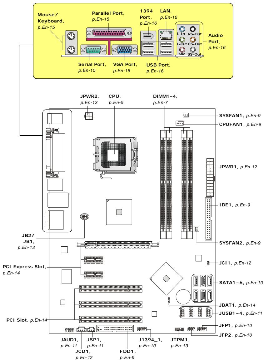
- 6 mounting holes
Quick Components Guide of P45 Neo/ G45 Neo/ P43 Neo Series (MS-7519 v1.X) Mainboard
Central Processing Unit: CPU
The mainboard supports Intel® processor. The mainboard uses a CPU socket called Socket 775 for easy CPU installation. If you do not have the CPU cooler, consult your dealer before turning on the computer.
For the latest information about CPU, please visit http://global.msi.com.tw/index.php? func=cpuform

Important
Overheating
Overheating will seriously damage the CPU and system. Always make sure the cooling fan can work properly to protect the CPU from overheating. Make sure that you apply an even layer of thermal paste (or thermal tape) between the CPU and the heatsink to enhance heat dissipation.
Replacing the CPU
While replacing the CPU, always turn off the ATX power supply or unplug the power supply's power cord from the grounded outlet first to ensure the safety of CPU.
Overclocking
This mainboard is designed to support overclocking. However, please make sure your components are able to tolerate such abnormal setting, while doing overclocking. Any attempt to operate beyond product specifications is not recommended. We do not guarantee the damages or risks caused by inadequate operation or beyond product specifications.
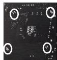
CPU & Cooler Installation Procedures for Socket 775
-
The CPU socket has a plastic cap on it to protect the contact from damage. Before you have installed the CPU, always cover it to protect the socket pin.
-
Remove the cap from lever hinge side.
-
The pins of socket reveal.
-
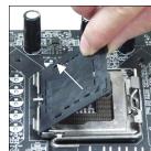
Open the load lever.
-
Lift the load lever up and open the load plate.
-
After confirming the CPU direction for correct mating, put down the CPU in the socket housing frame. Be sure to grasp on the edge of the CPU base. Note that the alignment keys are matched.
-
Visually inspect if the CPU is seated well into the socket. If not, take out the CPU with pure vertical motion and reinstall.
-
Cover the load plate onto the package.
-
Press down the load lever lightly onto the load plate, and then secure the lever with the hook under retention tab.
-
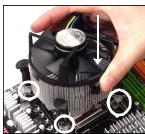
Align the holes on the mainboard with the cooler. Push down the cooler until its four clips get wedged into the holes of the mainboard.
-
Press the four hooks down to fasten the cooler. Then rotate the locking switch (refer to the correct direction marked on it) to lock the hooks.
-
Turn over the mainboard to confirm that the clip-ends are correctly inserted.
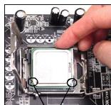
alignment key

Important
- Read the CPU status in BIOS.
- Whenever CPU is not installed, always protect your CPU socket pin with the plastic cap covered to avoid damaging.
- Mainboard photos shown in this section are for demonstration of the CPU/ cooler installation only. The appearance of your mainboard may vary depending on the model you purchase.
Memory
DDR2: DIMM1~4
These DIMM slots are used for installing memory modules.
For more information on compatible components, please visit http://global.msi.com.tw/index.php?func=testreport
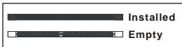
Dual-Channel Memory Population Rules
In Dual-Channel mode, the memory modules can transmit and receive data with two data bus lines simultaneously. Enabling Dual-Channel mode can enhance the system performance. Please refer to the following illustrations for population rules under Dual-Channel mode.
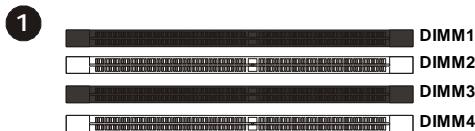
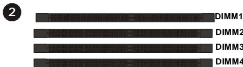

Important
- DDR2 memory modules are not interchangeable with DDR and the DDR2 standard is not backwards compatible. You should always install DDR2 memory modules in the DDR2 DIMM slots.
- In Dual-Channel mode, make sure that you install memory modules of the same type and density in different channel DIMM slots.
- To enable successful system boot-up, always insert the memory modules into the DIMM1 first.
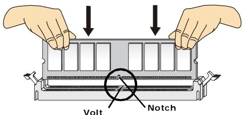
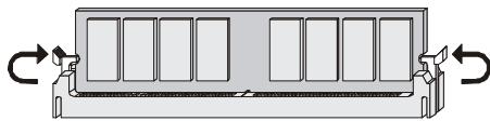
Installing Memory Modules
You can find the notch on the memory module and the volt on the DIMM slot. Follow the procedures below to install the memory module properly.
- The memory module has only one notch on the center and will only fit in the right orientation.
- Insert the memory module vertically into the DIMM slot. Then push it in until the golden finger on the memory module is deeply inserted in the DIMM slot. The plastic clip at each side of the DIMM slot will automatically close when the memory module is properly seated.

Important
You can barely see the golden finger if the memory module is properly inserted in the DIMM slot.
- Manually check if the memory module has been locked in place by the DIMM slot clips at the sides.
Connectors, Jumpers, Slots
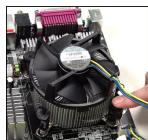
Fan Power Connectors: CPUFAN1/ SYSFAN1/ SYSFAN2
The fan power connectors support system cooling fan with +12V . The CPU FAN supports Smart FAN function. When connect the wire to the connectors, always take note that the red wire is the positive and should be connected to the +12V , the black wire is Ground and should be connected to GND. If the mainboard has a System Hardware Monitor chipset on-board, you must use a specially designed fan with speed sensor to take advantage of the fan control.
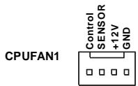


Important
- Please refer to the recommended CPU fans at processor's official website or consult the vendors for proper CPU cooling fan.
- CPUFAN supports fan control. You can install Dual Core Center utility that will automatically control the CPU fan speed according to the actual CPU temperature.
- Fan cooler set with 3 or 4 pins power connector are both available for CPUFAN.
Floppy Disk Drive Connector: FDD1
This connector supports 360KB, 720KB, 1.2MB, 1.44MB or 2.88MB floppy disk drive.
IDE connector: IDE1
This connector supports IDE hard disk drives, optical disk drives and other IDE devices.

Important
If you install two IDE devices on the same cable, you must configure the drives separately to Master/ Slave mode by setting jumpers. Refer to IDE device's documentation supplied by the vendors for jumper setting instructions.
Serial ATA Connector: SATA1~6
This connector is a high-speed Serial ATA interface port. Each connector can connect to one Serial ATA device.


Important
Please do not fold the Serial ATA cable into 90-degree angle. Otherwise, data loss may occur during transmission.
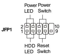
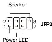
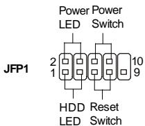
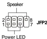
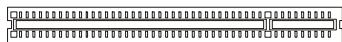
Front Panel Connectors: JFP1, JFP2
These connectors are for electrical connection to the front panel switches and LEDs. The JFP1 is compliant with Intel® Front Panel I/O Connectivity Design Guide.
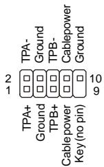
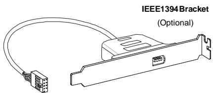
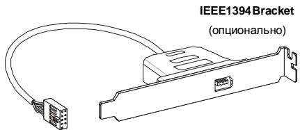
IEEE1394 Connector (Green): J1394_1 (optional)
This connector allows you to connect the IEEE1394 device via an optional IEEE1394 bracket.
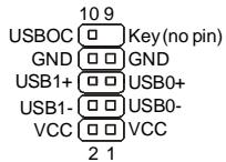
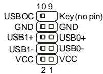
Front USB Connector (Yellow): JUSB1~4
This connector, compliant with Intel® I/O Connectivity Design Guide, is ideal for connecting high-speed USB interface peripherals such as USB HDD, digital cameras, MP3 players, printers, modems and the like.
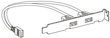
USB 2.0 Bracket
(Optional)

Important
Note that the pins of VCC and GND must be connected correctly to avoid possible damage.
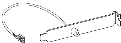
S/PDIF-Out Connector: JSP1
This connector is used to connect S/PDIF (Sony & Philips Digital Interconnect Format) interface for digital audio transmission.
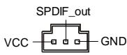

SPDIF Bracket (Optional)
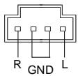
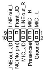
Front Panel Audio Connector: JAUD1
This connector allows you to connect the front panel audio and is compliant with Intel® Front Panel I/O Connectivity Design Guide.

CD-In Connector: JCD1
This connector is provided for external audio input.
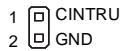
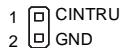
Chassis Intrusion Connector: JCI1
This connector connects to the chassis intrusion switch cable. If the chassis is opened, the chassis intrusion mechanism will be activated. The system will record this status and show a warning message on the screen. To clear the warning, you must enter the BIOS utility and clear the record.
Power Supply Attachment
Before inserting the power supply connector, always make sure that all components are installed properly to ensure that no damage will be caused. All power connectors on the mainboard have to connect to the ATX power supply and have to work together to ensure stable operation of the mainboard.
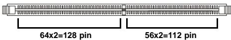
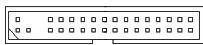
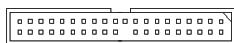
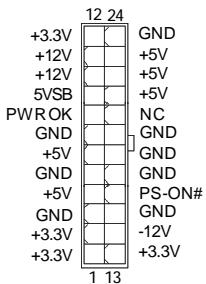
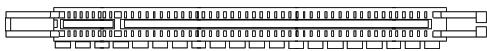
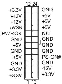
ATX 24-Pin Power Connector: JPWR1
This connector allows you to connect an ATX 24-pin power supply. To connect the ATX 24-pin power supply, make sure the plug of the power supply is inserted in the proper orientation and the pins are aligned. Then push down the power supply firmly into the connector.
You may use the 20-pin ATX power supply as you like. If you'd like to use the 20-pin ATX power supply, please plug your power supply along with pin 1 & pin 13.
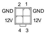
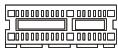
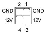
ATX 12V Power Connector (2x2-Pin): JPWR2
This 12V power connector is used to provide power to the CPU.
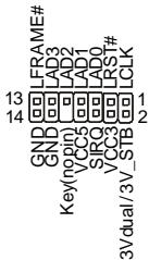
TPM Module Connector: JTPM1 (optional)
This connector connects to a TPM (Trusted Platform Module) module (optional). Please refer to the TPM security platform manual for more details and usages.
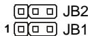
Hardware Overclock FSB Jumpers: JB1, JB2 (optional)
You can overclock the FSB to increase the processor frequency by changing the jumpers JB1 and JB2. Follow the instructions below to set the FSB.
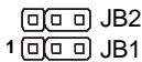
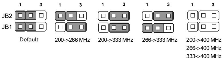

Important
- Make sure that you power off the system before changing the jumpers.
- Overclocking may cause instability or crash during boot, then please restore the jumpers to default.
Clear CMOS Jumper: JBAT1
There is a CMOS RAM onboard that has a power supply from an external battery to keep the data of system configuration. With the CMOS RAM, the system can automatically boot OS every time it is turned on. If you want to clear the system configuration, set the jumper to clear data.

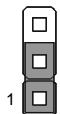
Keep Data (default)
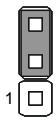
Clear Data

Important
You can clear CMOS by shorting 2-3 pin while the system is off. Then return to 1-2 pin position. Avoid clearing the CMOS while the system is on; it will damage the mainboard.
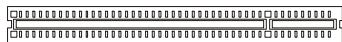
PCI Express Slot (x16/x1)
The PCI Express slot supports the PCI Express interface expansion card.
PCI Express x 16 Slot
PCI Express x 1 Slot
PCI (Peripheral Component Interconnect) Slot
The PCI slot supports LAN card, SCSI card, USB card, and other add-on cards that comply with PCI specifications.

Important
When adding or removing expansion cards, make sure that you unplug the power supply first. Meanwhile, read the documentation for the expansion card to configure any necessary hardware or software settings for the expansion card, such as jumpers, switches or BIOS configuration.
Back Panel
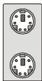
Mouse/Keyboard
The standard PS/2® mouse/keyboard DIN connector is for a PS/2® mouse/keyboard.

PS/2 Mouse connector (Green/ 6-pin female)
PS/2 Keyboard connector (Purple/ 6-pin female)
Parallel Port
A parallel port is a standard printer port that supports Enhanced Parallel Port (EPP) and Extended Capabilities Parallel Port (ECP) mode.
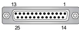
(25-pin female connector)
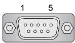
Serial Port
The serial port is a 16550A high speed communications port that sends/ receives 16 bytes FIFOs. You can attach a serial mouse or other serial devices directly to the connector.
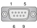
(9-Pin Male Connector)
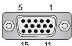
VGA Port
The DB15-pin female connector is provided for monitor.
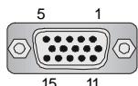
(15-Pin Female DIN Connector)
1394 Port
The IEEE1394 port on the back panel provides connection to IEEE1394 devices.

LAN
The standard RJ-45 LAN jack is for connection to the Local Area Network (LAN). You can connect a network cable to it.

| LED | Color | LED State | Condition |
| Left | Orange | Off | LAN link is not established. |
| On (steady state) | LAN link is established. | ||
| On (brighter & pulsing) | The computer is communicating with another computer on the LAN. | ||
| Right | Green | Off | 10 Mbit/sec data rate is selected. |
| On | 100 Mbit/sec data rate is selected. | ||
| Orange | On | 1000 Mbit/sec data rate is selected. |
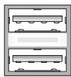
USB Port
The USB (Universal Serial Bus) port is for attaching USB devices such as keyboard, mouse, or other USB-compatible devices.
Audio Port Connectors
These audio connectors are used for audio devices. You can differentiate the color of the audio jacks for different audio sound effects.

Line-In (Blue) - Line In, is used for external CD player, tape player or other audio devices.
Line-Out (Green) - Line Out, is a connector for speakers or headphones.
MIC (Pink) - Mic In, is a connector for microphones.
RS-Out (Black) - Rear-Surround Out in 4/5.1/7.1 channel mode.
CS-Out (Orange) - Center/ Subwoofer Out in 5.1/ 7.1 channel mode.
SS-Out (Gray) - Side-Surround Out 7.1 channel mode.
BIOS Setup
This chapter provides basic information on the BIOS Setup program and allows you to configure the system for optimum use. You may need to run the Setup program when:
- An error message appears on the screen during the system booting up, and requests you to run BIOS SETUP.
- You want to change the default settings for customized features.

Important
- The items under each BIOS category described in this chapter are under continuous update for better system performance. Therefore, the description may be slightly different from the latest BIOS and should be held for reference only.
- Upon boot-up, the 1st line appearing after the memory count is the BIOS version. It is usually in the format:
A7519IMS V1.0 051508 where:
1st digit refers to BIOS maker as A = AMI , W = AWARD , and P = PHOENIX .
2nd - 5th digit refers to the model number.
6th refers to the Chipset vender as A = AMD , I = Intel , V = VIA , N = Nvidia , U = ULi .
7th - 8th digit refers to the customer as MS = all standard customers.
V1.0 refers to the BIOS version.
051508 refers to the date this BIOS was released.
Entering Setup
Power on the computer and the system will start POST (Power On Self Test) process. When the message below appears on the screen, press key to enter Setup.
Press DEL to enter SETUP
If the message disappears before you respond and you still wish to enter Setup, restart the system by turning it OFF and On or pressing the RESET button. You may also restart the system by simultaneously pressing <Ctrl> , <Alt> , and <Delete> keys.
Getting Help
After entering the Setup menu, the first menu you will see is the Main Menu.
Main Menu
The main menu lists the setup functions you can make changes to. You can use the arrow keys (↑↓) to select the item. The on-line description of the highlighted setup function is displayed at the bottom of the screen.
Sub-Menu
If you find a right pointer symbol (as shown in the right view) appears to the left of certain fields that means a sub-menu containing additional options can be launched from this field. You can use control keys ( ) to highlight the field and press
SATA1
SATA2
SATA3
SATA4
keys to enter values and move from field to field within a sub-menu. If you want to return to the main menu, just press <Esc> .
General Help
The BIOS setup program provides a General Help screen. You can call up this screen from any menu by simply pressing <F1>. The Help screen lists the appropriate keys to use and the possible selections for the highlighted item. Press <Esc> to exit the Help screen.
The Main Menu
Once you enter AMI® or AWARD® BIOS CMOS Setup Utility, the Main Menu will appear on the screen. The Main Menu allows you to select from ten setup functions and two exit choices. Use arrow keys to select among the items and press
| Standard CMOS Features | Cell Menu |
| Advanced BIOS Features | Load Fail-Safe Defaults |
| Integrated Peripherals | Load Optimized Defaults |
| Power Management Setup | Save & Exit Setup |
| H/W Monitor | Exit Without Saving |
| BIOS Setting Password |
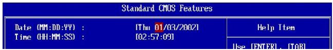
Standard CMOS Features
Use this menu for basic system configurations, such as time, date etc.
Advanced BIOS Features
Use this menu to setup the items of special enhanced features.
Integrated Peripherals
Use this menu to specify your settings for integrated peripherals.
Power Management Setup
Use this menu to specify your settings for power management.
H/W Monitor
This entry shows your PC health status.
BIOS Setting Password
Use this menu to set the Password.
Cell Menu
Use this menu to specify your settings for frequency/voltage control and overclocking.
Load Fail-Safe Defaults
Use this menu to load the default values set by the BIOS vendor for stable system performance.
Load Optimized Defaults
Use this menu to load the default values set by the mainboard manufacturer specifically for optimal performance of the mainboard.
Save & Exit Setup
Save changes to CMOS and exit setup.
Exit Without Saving
Abandon all changes and exit setup.
When enter the BIOS Setup utility, follow the processes below for general use.
- Load Optimized Defaults: Use control keys ( ) to highlight the Load Optimized Defaults field and press
, a message as below appears:

Select [Ok] and press Enter to load the default settings for optimal system performance.
- Setup Date/ Time : Select the Standard CMOS Features and press
to enter the Standard CMOS Features-menu. Adjust the Date, Time fields.
- Save & Exit Setup : Use control keys (↑ ↓) to highlight the Save & Exit Setup field and press
, a message as below appears:
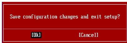
Select [Ok] and press Enter to save the configurations and exit BIOS Setup utility.

Important
The configuration above are for general use only. If you need the detailed settings of BIOS, please see the manual in English version on MSI website.
Software Information
Take out the Driver/Utility CD that is included in the mainboard package, and place it into the CD-ROM driver. The installation will auto-run, simply click the driver or utility and follow the pop-up screen to complete the installation. The Driver/Utility CD contains the:
Driver menu - The Driver menu shows the available drivers. Install the driver by your desire and to activate the device.
Utility menu - The Utility menu shows the software applications that the mainboard supports.
WebSite menu- The WebSite menu shows the necessary websites.

Important
Please visit the MSI website to get the latest drivers and BIOS for better system performance.
P45 Neo/ G45 Neo
/P43 Neo
Benutzerhandbuch
Deutsch
Spezifikationen
Prozessoren
FSB (Front-Side-Bus)
- 1600* (OC)/ 1333/ 1066/ 800 MHz
Chipsatz
- North-Bridge: Intel® P45/ G45/ P43 Chipsatz
- South-Bridge: Intel® ICH10 Chipsatz
Speicher
Frontpanel Anschlüsse: JFP1, JFP2
PCI (Peripheral Component Interconnect) Slot
Press DEL to enter SETUP
Standard CMOS Features
Advanced BIOS Features
Integrated Peripherals
Power Management Setup
H/V Monitor
BIOS Setting Password
Cell Menu Load Fail-Safe Defaults Load Optimized Defaults Save 8 Exit Setup Exit Without Saving
Standard CMOS Features
Advanced BIOS Features
Integrated Peripherals
BIOS Setting Password
Slot PCI (Peripheral Component Interconnect)
| Standard CMOS Features | Cell Menu |
| Advanced BIOS Features | Load Fail-Safe Defaults |
| Integrated Peripherals | Load Optimized Defaults |
| Power Management Setup | Save & Exit Setup |
| H/W Monitor | Exit Without Saving |
| BIOS Setting Password |
Standard CMOS Features (Fonctions CMOS standard)
KoHneKTopbI nepeDneHaeneJ: JFP1, JFP2
3TN KOHHeKTopbl NcNoIb3yIOCTa IIN NOKlnOeHn KHOJOK INHdNKaTOPOB, paCNOJoxeHHbIX Ha nepeDne HaneHn Kopnyca. KOHHeKTop JFP1 COOTBeTCTByET pykoBoDCTby Intel® Front Panel I/O Connectivity Design Guide.
IEEE1394 Connector (3eIeHbI): J1394_1 (onzioHOaJIbHO)
3TOT KOHNKTop no3BONJET NOdkNIOUHTb NOPtI IEEE1394 Ha BbHOCHOIJaHKe IEEE1394.

BbIOCHbIe NopTbI USB (KeJIbI KOHHeKTop):JUSB1\~4
Pa3bem, COOTBeTCTByET cneuΦnKaunl Intel® I/O Connectivity Design, nIealbHO IOxODHTI JIIOKIIHcHn TaKHX BILCOKOCOPoCThIX nepuΦepnHBIX yCTpoCTB, KaK USB HDD, uΦpObIe KAmepbl, MP3 nIeepbl, npInHTepbl nM nIo06HbIe.
SPDIF Bracket
(ONUHOHaJIbHO)
BbHocHoi pa3bem aydno:JAUD1
3TOT KOHHeKTop P03B0JnEeIPOkJIIOuHTb BbIOHOcHoi pa3bEm ayDnO Ha nepeJeHne NaHeHn COOTBeTCTByeT pyKOBoDCTBy I/O Connectivity Design Guide.
KOHHekTop CD-In: JCD1
3TOT KOHHeKTop npEHa3NaueH IJI NOIKNIOeHn BHeuHO BXOa ayNo.

Pa3bEm DaTUnka OTKpbIbAHnK Kopnyca: JCI1
K 3TOMY KOHHeKToPny noKnHouaetc Ka6eJIb DaTuNka, yCTaHOBneHHORo B Kopnyce. PnO tKpbIbAHnn KOpnyca erO mexAHn3M aKtINBn3npyeCz.CnCTema 3anOMnHaet 3TO c6bItne N BbIaet npEynpeXJdHne Ha 3kpaH. PpeynpeXJdHne MoXHO OTKnHOnHTb B NaCTpOikax BIOS.
DONONHEHNE HCTOCHNKA NITAHNA
Ipeep noiklnouhenem pa3bema nitaHnra, BO n36bexaHne nobpexdeHn o63ateJbHo y6eintecb, yTO BCE KOMnoHentbl yctahOBHeHbl npabInbHo. Bce pa3beMbl nItanHndoJXhbl 6b1b noKIOKNoHcHbl K 6nOky nItanHnA TX dna o6nnerHn ctaBnBHO pa60tbnCnCTEMHO nIaTbl.
24-KoHTaKTHbI pa3bEm nHTaHn ATX: JPWR1
3TOT pa3bem IO3BOJnIeT NOkJIyOuHTb 24-KoHTaKTHbI NITAHmA ATX.ДЯ NOkJIyOeHnI INCTOHyNka y6eIntecb, YTO erO pa3bem I KOHTaKtBIpaBnIbHO copneHTnpoBaHbI. 3aTeM IIIOTHO BCTaBbTe erO B pa3bem Ha cnCTeMHOn PnATE.
Bb taKxe moXeTe nCnoIb3ObaTb 20-koTHaKTHbI ATX 6nok nItaHnI. Pp nCnoIb3ObaHmN 20-koTHaKTHoro pa3bema, noDkJIouaIte erO BdoJI bKOHTaKTOB 1 n 13.
Pa3bem nHTaHnATX 12V (2x2-Pin): JPWR2
3ToT pa3bem nItaHn 12B nCnoJb3yetc dIy oBecepeHn nItaHn npOeccopa.
Pa3bemTPM MoDyIa: JTPM1 (OuHOnaJIbHO)
Ipepebny annapaTHoro pa3roHa FSB:JB1,JB2 (onuHOaHbHo)
IpeceTaHOBka nepeMbueK JB1 n JB2 no3BoJraT pa3oHaTb FSB dIy yBeIuYeHnna YacToTb npouecoppa. CneDuYte HnKeCneDyuOuM yka3aHnem dIy ycTaHOBKn FSB.
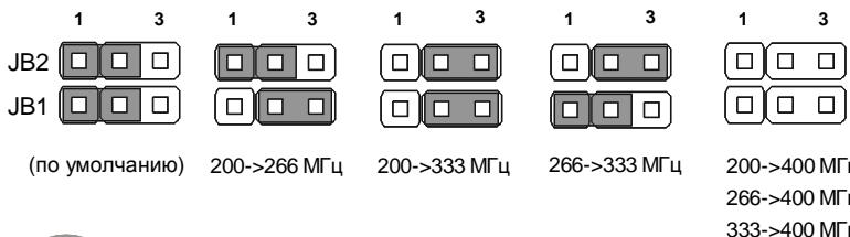

BhimaHne
- Перед пексановский лесьчес уб dedumecь в мом, чу осменник риманя omknioyuhen.
- EcIu pa3a0n 6b3b1eaem Hecma6unbHocmb Cucmembu unu npo6neMb npu 3aay3ke, mo 8occmahOusme nepembyku e noJoxeHue no ymonuaHIO.
Cnot PCI (Peripheral Component Interconnect)
Cnot PCI no3b0n8eYcTaHOBnTB KapTy LAN, SCSI, USB n dpyrne donoHnTeHbHbe KapTb paCunpeHHa, KOToPbE COOTBeCTByOT xapaKtepunctkam PCI.

BHMaHne
Peped ycmaHOKou unu u3eneueHuem Kapm paWupHeu y6eDumecb,mo Kaebn numaHua omKnIOHeu om 3neKmpueCko cemu. Pnpumme dokyEmHaUo Ha Kapmy paWupHeu u bInOnHume HeobxOdbMble annapamMbte unu npOapAmMbte ycmaHOku dR daHou nnambl, maKue ka Kepmblyku, nepeKnIOaHenu unu konfouyaPauu BOIS.
3aHnaHeIb
Pa3bemblmbiwn/KnabNaTpybl
CtaHapThbIe pa3bEmbl DIN PS/2® dЯ noДКЛЮЧЕня Мыш/NkaBnAtypblc nHTeppeiom PS/2®.
Pa3bem PS/2ДПЯ МbliIN (6-KoHTaKTHaJ 3eJIeHaj p03eTKa)
Pa3bem PS/2ДЯ КлаваТурь (6-KoHTaKTHaФиОЛTeВа роЗЕТka)
Pa3bem npapJIeJIbHoro nopTa
IpaannelbHn npot - 3to cTaNapThb npot IJnI npntepa. OH noDaepxNbae pexmbEPP (ycobepwehctBoBaHHn npapannelbHn npot) n ECP (napanneJIbHn npot cdoONHTeBbIMN BO3MOXHOCTMn).

(25-KoHTaKTHaY po3eTKa)
Pa3bem nocJeIOBaTeJIbHoro nopTa
3TO BbICOKocopocTHoN NOcJIeOBaTeNbHbI NOpT Cb3n 16550A c 16-6HTHO nepeaueFIFO.K 3ToMy pa3bEmy MoKHO HeNoCpeDCTBeHHO NODKJIIOHTbMbIb dIa NocJIeOBaTeNbHorO NoP Ta HIN DpyroE yCTpOCTBO.
6 9
(9-KOHTaKTHaBbNka)
Pa3bem VGA
15-KoHTaKTHa pO3eKa DB nI NOkJIIOUeHnMa MOHITopa.
(15-KoHTaKTHaRa po3eTka DIN)
Ioprt 1394
BbXoD Line (Tony60) - NHeHb BxO, nCNoIb3yETc dIg NOKIOUeHn BHeuHrO CD npOnrpBaTeJ, mHarntofoHa nn DpynX 3ByKObIx yCTpoNCTB.
BbIXoD Line (3eIeHbI) -JIInHeHbI BbIXoD IJIЯ NOJKnIOUChEHNa HayuHnKOB INI KONOHOK.
MIC (Po30BbI) - Pa3bEmДлЯ подклоченma MnkpofoHa.
BbIXoR RS (UepHbI) - BbIXoHa 3aAnHe KOIoHKn BpeKmE 4/5.1/7.1.
BbIXoD CS (OpaXeBbI) - BbIXoHa ueHTpaJIbHyU KOIoHky u ca6ByΦep B pexIme 5.1/7.1.
BbIXoD SS (Cepb) - BbIXoHa 60KOBbie KOJIOHKn BpeKIme 7.1.
Hac troponka BIOS
B 3toi rnaBe npnboaTcO cHOBhIe CbeEHHo pexmHe hactpoKn BIOS (BIOS SETUP), KOtOpbI n03BoJrEt yCTaHOBHTb ONTMaJIbNHyO KOHfNpyauuNo cntembl. 3ToT peKIM MoKET NOTpe6oBaTbcra B cJeDyUoJx CNyuaX:
1a8ykea coomeemcyeem u3oomeumnIO BIOS (A = AMI, W = AWARD, u P = PHOENIX).
Cneyouue 4 ucpbcoomemcmeyiom Homepy Modeu.
Cleedyouza byka obozhaem noctema quncema (A = ATi, I = Intel, V = VIA, N = Nvidia, U = ULi).
Cneyouue 26kybbl o63naum 3ka3uKa MS = cmahdapmbl 3ka3uk.
V1.0 coomecmeyem Homepy eepcuu BIOS.
051508 dama binycka BIOS.
Bxod B pexm HactpoKn
BkIIOHTe nITaHne KOMbIOTepa. PnI 3OTm 3aNcyTcT npOeUpya POST (TeCT BkIIIOUeHnIITAHn).KOrDa Ha 3KpaHe NpOBuTcR npNBedeHHOe HnJke coo6UeHne, HauKMITE KNaBnSy ДЯ BXOa B pexMn HacTpOKn.
Press DEL to enter SETUP
Ecni coo6eHne nCue3IIO, a BbI He ycneIIN HaxaTB KIaNbIuY, nepe3anyctnte CnCTeMy, BblKnIOuNIB nCHOBa BKJIIOUH NITaHNe, IIN HaxaTB KONKy RESET. MoKHO, TaKKe, nepe3anyctntb CnCTeMy, Haxab OndOBpemEnHO KNaBUns
PexmHaCTpoKn
BoiIaBpeKIM HacTpoKIn, Bbl cpa3y yBnDnte InaBHOe MeHIO.
Main Menu(TnaBHe MeHIO)
Главhoe MeHIO COdepKHT CnncOK HAcTpoEK, KOtOpbIe Bbl MoKTe N3MeHNTb.ДлЯ Bbl6opa MoXHO NcNoJIb3ObATb KNaBnIu C O CtrpenKaMn (↑↓).CnpaBka O bbl6paHHo HAcTpoKe OTobpaKaTaCBAHKnHeY qactn 3KpaHa.
IopmeHIO
EcIn Bbl ObnapyKHTe, YTO CnEBA OT NyHKTa MeHIO NMeETc3Nak npaboro yka3aTeTn (kak NOKa3aHO Cnpaba) 3TO O3NaayehaJIuYne NOmHeo, CoedePjAaero DOnOJHNTeNbHbIe HAcTPOKn KOTOpBle MOXHO CdeJaB B 3Tom NyHKTe.
SATA1
SATA2
SATA3
SATA4
IcnoB3yTe ynpabnlouine KnaBnun ( ) nIe BbIbopa, a 3aTe m Haxmnte
Побрбая справka
B pexime hactpoi KN BIOS nmeetc B03MOXHOCTb nolyeHnnoDpOboHn cnpaBKn. Ee moxHO Bbl3BaTb n3 lioboro meHIO npocTbIM haxaTneM F1>. B okHe cnpaBKn 6ydt nepeuNCJIeHb BCE BO3MOXHbIe HacTpoi KN B bbl6paHHom nyHKTe MeHIO. HaxMMTe
The Main Menu (Главhoe MeHIO)
| Standard CMOS Features | Cell Menu |
| Advanced BIOS Features | Load Fail-Safe Defaults |
| Integrated Peripherals | Load Optimized Defaults |
| Power Management Setup | Save & Exit Setup |
| H/W Monitor | Exit Without Saving |
| BIOS Setting Password |
Standard CMOS Features (CtahapThbIe yHKcIM CMOS)
3To MeHIO N03BONJe TcTaHOBnTb OCHOBHbIe npaMeTpbl KOHpNpyaun CnCTembl (daTy, BpeMra, n T.d.)
Integrated Peripherals (BcTpoeHHbIe nepuΦepnHbIe yctpoiCTBa)
3To MeHIO NcNoJIb3yETcIЯ NaCTpoIKI npaMeTPOB BCtPoEHhIx nepiΦepnIHbIX ycTPOICTB.
Power Management Setup (HactpoKa ynpaBLeHnI nITaHnEM)
3To MeHIO N03B0Jare 3aadTb npaMeTpbl ynpaBHeHn nTuHnem CnCTeMbI.
H/W Monitor (Montop annapathouactn)
3TOT nyHKT OTO6paxaet COCTOARHe annpapathoJyactn PK.
HaxmTe [Ok], cyobc coxpaHTb KOhpyaunu N BbTn n3 BIOS Setup.

BHMaHne
Ppueedennn a bIwe konduaypaun noxdum dna oou npumehn. Ecnne am mpeyomc6oonee monkue hacmpouku BIOS, opbamecb K anauckou eepcuu pykoodmehaee-caume MSl.
CBeDeHnO npOrpaMMHom o6ecneueHn
YctaHOBInTe B CD npNbOd nck Driver/Utility (IpaaiBepbl yTuNTnbl) n3 KOMPNeKta NOCTABKn CnCTeMHo NpTaBl. AToMaTnuecck 3anyCTnTCr IHCTaJIpyu. IpoCtO HaxMITE Ha Ha3BaHHe dpaiBepa/ yTuNTbl n CneDuYte IHCTpyKzUm Ha 3kPaHe dJa 3aBepSeHHa HcTaNauu. DnCK Driver/Utility codepXHT:
Driver menu (Mehio dpaBepOB) - 13 ImeIoUxCra dpaBepOB Bb6epnte HxKbI dJaakTBAcun yctpOCTBa.
Utility menu (Meho ytnnt) - Coepknt npknadhble nporpaMMbl nnoedpKcnCTemHn nnatbl.
WebSite menu (MeHIO Be6caTob) - CopejXnt CnncOK Heo6xOIMbIX Be6caTob.

BhimaHne
Ecnu je aam mpebyomc8oonee moKue hacmpoukU BIOS, obpamumecb K anuuckou epcuu pykoedcmba ha eeb-caume MSl.