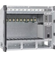
UFG 810 - Server KATHREIN - Free user manual and instructions
Find the device manual for free UFG 810 KATHREIN in PDF.


| Product Type | Server |
| Brand | Kathrein |
| Model | UFG 810 |
| Dimensions (W x H x D) | Approx. 430 x 44 x 300 mm (19-inch rack mount) |
| Weight | Approx. 4.5 kg |
| Power Supply | 100-240 V AC, 50-60 Hz, max. 60 W |
| Operating Temperature | 0°C to 40°C |
| Storage Temperature | -20°C to 60°C |
| Main Functions | Data processing, streaming, network storage, media server |
| Interfaces | Ethernet (RJ45), USB 3.0, HDMI, audio out |
| Supported Protocols | HTTP, FTP, DLNA, UPnP |
| Storage Capacity | Supports up to 2 HDDs (3.5-inch SATA, not included) |
| RAID Support | RAID 0/1 (optional) |
| Software Features | Web-based management, remote access, backup scheduling |
| Cooling | Internal fan, temperature-controlled |
| Maintenance & Cleaning | Disconnect power, wipe with dry cloth, avoid liquids |
| Safety | CE, RoHS compliant; use only supplied power adapter |
| Spare Parts & Repairability | Replaceable fan and power supply; HDDs user-replaceable |
Frequently Asked Questions - UFG 810 KATHREIN
User questions about UFG 810 KATHREIN
0 question about this device. Answer the ones you know or ask your own.
Ask a new question about this device
Download the instructions for your Server in PDF format for free! Find your manual UFG 810 - KATHREIN and take your electronic device back in hand. On this page are published all the documents necessary for the use of your device. UFG 810 by KATHREIN.
USER MANUAL UFG 810 KATHREIN
natural_image
Technical line drawing of a mechanical component with mounting holes and a button (no text or symbols)
ACHTUNG
natural_image
Internal view of a network equipment chassis with multiple Ethernet ports and cables (no visible text or labels)UFOcompact plus® Base Unit
UFO compact plus
About This Manual
This document is part of the product.
▶ Install and use the unit only after you have read and understood this document.
▶ Keep this document for reference throughout the life of the device. Pass this document on to the next owner and user of the device.
For the current version of this manual, go to the Kathrein website www.kathrein-ds.com.
Features
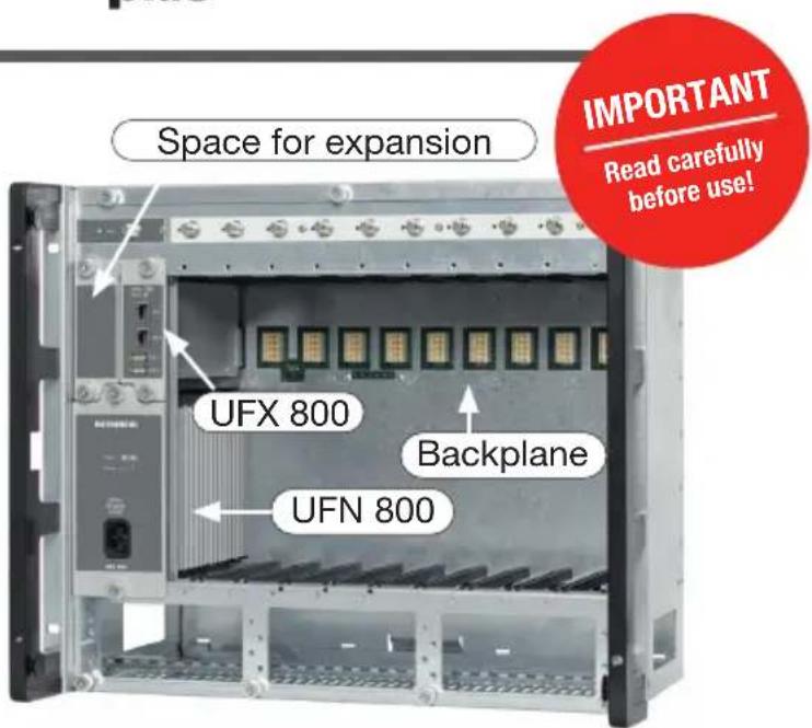
■ Ten hot-plug insert positions for UFOcompact plus® modules
■ Three separate hot-plug system insert positions for power supply unit (UFN 800), control module (UFX 800) and extensions (e.g. UVO 830, etc.)
■ UFO® compact series channel units can be installed and operated over the UFZ 800 adapter. The system is downwards compatible
■ Module voltage supply and communication over high-speed backplane
Scope of Delivery
- base unit UFG 810
- power cable
- set of screws for installation in 19" cabinet
- instructions for use UFG 810, open Source license texts
• 9 x terminating resistor 75 Ω
- Secure heat dissipation is ensured using two energy-saving, monitored extractor fans and optimised air ducting over the module's cooling elements
■ Height: Nine RUs for wall mounting or 19" racks
■ Ample free space at the bottom of the module carrier for insertion of the external leads and adapter
■ Completely pre-assembled, with power supply, output coupler, cover and control module
■ Three input splitters (UFZ 300) can be affi xed to the UFG 810 housing
Intended Use
The base unit UFG 810 is used for the accommodation and operation of headend modules and channel units from the UFOcompact plus and UFOcompact range of products. A channel unit adapter of the UFZ 800 type is required for the operation of UFOcompact channel units.
The UFG 810 provides infrastructure for ten modules of channel units. The base unit is equipped with the UFN 800 power supply unit and the UFX 800 control unit ex works. As an option, it is possible to insert the UVO 830 amplifier at the specified location.
The UFG 810 is actively ventilated, remotely controlled over an IP connection, cascadable and redundancy-capable due to the UFZ 810 cable. The latter is used to connect two base units, the power supply units of which automatically switch to the half-load parallel operation.
All components of the UFG 810 are intended exclusively for the application in the UFG 810 as well as in satellite, cable or antenna reception systems. Any other use of failure to comply with these instructions will result in voiding of the guarantee or warranty.
Transportation and Storage
▶ Transport and storage the unit in its original packaging.
▶ Protect the unit against dust, dirt, moisture and direct sunlight.
▶ Transport and store the unit in the permissible temperature range from -25 to +70 °C. Make sure there is no water condensation bildup.
Safety Instructions

WARNING Hot surfaces!
During normal operation and increased ambient temperature, the surface temperature may exceed 60 °C. Should thermal cut-out occur, there is danger due to hot metal parts.
▶ Do not touch!

WARNING Current-carrying device!
▶ Do not open or tamper with the device.
When working on the system always unplug the power supply unit from the wall socket.
▶ Ensure adequate clearance of at least 5 cm to all sides.
▶ Do not mount the unit overhead.
▶ Free circulation of air must be possible to discharge the heat emitted by the unit. Danger of overheating!
▶ Bear in mind that the only reliable method of disconnecting the UFG 810 power supply from the mains is to unplug it.
▶ Connect the module carrier to the wall outlet with a protective earthing.
▶ Make sure that the mains plug are easily accessible and operable.

WARNING
Risk of serious injury!
▶ Keep fingers and other body parts away from any moving components, at all times, e.g. extractor fans.
The unit must be installed by qualified personnel in compliance with the local and national security standards and regulations.
The equipment may only be installed in dry areas indoors on a solid surface.
▶ Do not mount it on or against easily fl ammable materials.
▶ Connect the equipment to the equipotential bonding rail (Cu, at least 4 mm²).
▶ Make sure the safety regulations set out in the current EN 60728-11 and EN 60065 standards are complied with.
▶ Use an RF connector,75 Ω (series F) according to EN 61169-24.

For wall installation, earth the system with the earthing clamp pictured. If required, the earthing clamp may also be installed on the opposite side of the base unit.

natural_image
Technical line drawing of a vehicle rear panel with buttons and a battery symbol (no text or labels)
NOTICE
Risk of damage to the product!
▶ Do not ship the base unit with modules inserted.
When using UFOcompact plus® in publicly accessible spaces, close the front cover of the system.
▶ Measurements on the backplane plugs are not allowed (Risk of short circuits!)
▶ Do not cover the louvres.
Do not place liquid-fi lled items on top of the power supply unit or the fans.
▶ Do not expose the power supply unit and louvres to dripping or splashing water.
▶ Only operate the unit with functioning extractor fans.
Mounting the Unit
Mounting Possibilities
The base unit UFG 810 is not only designed for wall mounting but also for installation in 19" cabinets.
Wall mounting:
The module carrier can be directly fixed to the wall using three screws ( 6 – 8 mm):
• Weight when fully equipped: approx. 25 kg.
- Dimensions for wall mounting: (see illustration of UFG 810 rear panel below, values in mm)

Installation in 19" Cabinet
In air-conditioned rooms with a maximum ambient temperature of 40 °C, up to four base units can be stacked one above the other in a standard 19" cabinet (with 40 RU).
A minimum of one height unit (1 RU) clearance must be left between each of the units.
Tipp
For installation in 19" racks, the two side pieces and the earth clip must be removed.
Mounting the Unit
- Fit the base unit.
- Connect potential equalisation according to the regulations (DIN EN 60728-11 and DIN EN 60065).
- Prepare/park Sat-IF cables/drop cables (H and V) in the bottom section. The bottom plate can be removed to insert or install cables.
- Connect the 230 V power cable which can also be lead/laid in the bottom section.
Setting the Unit into Operation
- Install the system as described in Mounting the Unit.
- Insert UFOcompact plus modules and tighten. It is also possible to build in older UFOcompact channel units. To do so, one UFZ 800 (order no. 20610124) channel unit adapter is required per one UFOcompact channel unit
- Sat-IF drop cables (H and V) can be inserted directly into the modules (F-type connector) or through a matrix. All UFOcompact plus® modules are DiSEqC™-capable.
- Insert RF connector cable(s) (F-Quick) between the output socket(s) of the module (F-type connector) and the output coupler in the head piece of the base unit. Fit unused RF female connectors with terminating resistors.
- Connect system to network
- Confi gure the UFOcompact plus® modules and UFOcompact® channel units over a management interface of the UFX 800 central control module. This can be done on site with a laptop or over remote control via TCP/IP using the USW 800 management software (available for free download at www.kathrein-ds.com).
Tipp
If the power supply system does not maintain the specified permissible voltage values (230 V\~ ± 10%), we recommend using an uninterrupted power supply unit that compensates this weakness of the electricity network.
Operating the Unit
Control of the channel unit is done over the UFX 800 control module, the control interface for all modules and channel units installed in the UFG 810 base unit.
Operation of the channel unit is performed via the graphical user interface (GUI) of the USW 800 control software. Instructions on how to operate are found in the USW 800 operating manual supplied as a pdf in the management software.
Tipp
The current version of the USW 800 and its operation manual are available for free download at the Kathrein website www.kathrein-ds.com.
Operating the USW 800 Management Software
-
Install the USW 800 Management software on your computer.
-
Connect your computer's LAN/Ethernet port to one of the two LAN/Ethernet ports on the UFX 800 (CAT 5 or higher is recommended, twisted pair).
→ You have access to all the device parameters.
- Consult the USW 800 user manual for further setting instructions.
Set-up Variant (Example)

natural_image
Internal view of an industrial control module with multiple Ethernet modules and visible wiring (no text or symbols)In the picture above you see a UFG 810 fitted with two different types of modules:
- on the left the new UFOcompact plus® modules,
• and on the right the old UFOcompact® channel units.
The channel unit adapter UFZ 800 required for connection of the UFOcompact® channel units is positioned between the backplane and the UFOcompact® channel units.
Technical Data
| Type of Mounting Installation in 19" Cabinets or for Wall Mounting | |
| Number of hot-plug system insert positions | |
| Power supply (UFN 800, 20610121) | |
| Mains voltage V/Hz 230 ± 10 % / 50 ... 60 | |
| Power consumption, nax. W 437 | |
| Secondary voltage/ max. permissible current | V/A 12.3/32.5 |
| Signalisation LED Green (normal operation); red (undervoltage or excess current); red, fl ashing (overvoltage) | |
| Output Data | |
| Connection loss dB typ. 15 | |
| General | |
| Extractor fan 2 | |
| Dimensions (H x W x D) mm 399 x 483 x 266 | |
| Permissible ambient tem-perature | °C -20 ... +50 |
| Weight | kg 12.8 |
Maintenance

WARNING
Risk of injury!
▶ Keep fingers and other body parts away from any moving components at all times, e.g. extractor fans.
In order to guarantee a long and undisturbed service life, we recommend servicing the systems on a regular basis, e.g. cleaning the fans or louvres at least once a year to remove dust and other impurities. Furthermore, we recommend exchanging the fans every 6 – 7 years. The fan unit can be completely removed for exchange. The fans can also be exchanged without interrupting operation; however, this is not recommended.
In general, no tools are required.
▶ Perform the fan exchange quickly in order to prevent system overheating.
The exchange procedure is to be done as follows:
- Loosen the three fixing screws (thumbscrews) on the front.
- Lift the fan unit a few centimetres and loosen the two optical connectors for the individual fans (12 V) in the left section of the system.
- Completely pull out the fan unit towards the front.
- Exchange individual fans.
- Assemble the fan unit in reverse order.
Repair and Replacement
If, after having read this manual you still have unanswered questions or cannot solve a problem, contact our Customer Service Helpline at +49 731 270 909 70.
For information about repairs, visit our website https://www.kathrein-ds.com.
Furthermore, you can contact our regional service centre:
Regional Service Centre
Electronic equipment is not household waste in accordance with directive 2002/96/EC OF THE EUROPEAN PARLIAMENT AND THE COUNCIL dated 27th January 2003 on used electrical and electronic equipment, it must be disposed of properly.
At the end of its service life, take this unit for disposal to an appropriate official collection point.


- ACHTUNG
- UFOcompact plus® Base Unit
- UFO compact plus
- About This Manual
- Features
- Scope of Delivery
- Intended Use
- Transportation and Storage
- Safety Instructions
- WARNING Hot surfaces!
- WARNING Current-carrying device!
- WARNING
- Risk of serious injury!
- NOTICE
- Risk of damage to the product!
- Mounting the Unit
- Mounting Possibilities
- Wall mounting:
- Installation in 19" Cabinet
- Tipp
- Setting the Unit into Operation
- Operating the Unit
- Operating the USW 800 Management Software
- Set-up Variant (Example)
- Maintenance
- Risk of injury!
- Repair and Replacement
- Regional Service Centre
Brand : KATHREIN
Model : UFG 810
Category : Server