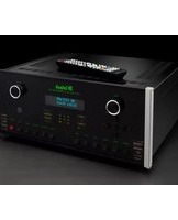
MX123 - Controller MCINTOSH - Free user manual and instructions
Find the device manual for free MX123 MCINTOSH in PDF.


| Product Type | A/V Controller (Preamp/Processor) |
| Dimensions (W x H x D) | 17.5 in x 7.5 in x 19 in (44.5 cm x 19 cm x 48.3 cm) |
| Weight | 45 lbs (20.4 kg) |
| Power Consumption | 150W (standby <0.5W) |
| Power Supply | 100-240V AC, 50/60 Hz |
| Video Inputs | 7 x HDMI 2.1 (8K/60Hz, 4K/120Hz), 2 x Component Video |
| Video Outputs | 2 x HDMI 2.1 (eARC), 1 x Composite Monitor |
| Audio Inputs | 6 x Analog RCA, 2 x XLR, 3 x Digital Optical, 2 x Digital Coaxial |
| Audio Outputs | 12-channel XLR balanced, 12-channel RCA unbalanced, 2 x Subwoofer RCA |
| Surround Formats | Dolby Atmos, DTS:X, Auro-3D, IMAX Enhanced |
| Room Correction | Dirac Live (full bandwidth) |
| Video Processing | 8K upscaling, HDR10+, Dolby Vision, HLG |
| Streaming | Supports external streamers via HDMI/optical; AirPlay 2 built-in |
| Control | IR, RS-232, Ethernet, Trigger, IP control (web UI) |
| Front Panel Display | High-resolution LCD with McIntosh blue meters |
| Maintenance | Clean exterior with a soft, dry cloth; do not use abrasives or liquids |
| Safety | Do not obstruct ventilation slots; avoid moisture and extreme temperatures |
| Repair & Spare Parts | Contact an authorized McIntosh service center for repairs or parts |
| Warranty | 3-year limited warranty (parts and labor) |
Frequently Asked Questions - MX123 MCINTOSH
User questions about MX123 MCINTOSH
0 question about this device. Answer the ones you know or ask your own.
Ask a new question about this device
Download the instructions for your Controller in PDF format for free! Find your manual MX123 - MCINTOSH and take your electronic device back in hand. On this page are published all the documents necessary for the use of your device. MX123 by MCINTOSH.
USER MANUAL MX123 MCINTOSH
McIntosh Laboratory, Inc. 2 Chambers Street Binghamton, New York 13903-2699 Phone: 607-723-3512 www.mcintoshlabs.com
MX123
A/V Processor
Owner's Manual


The MX123 Audio/Visual Processor marries a long tradition of uncompromising quality with the latest home theater technologies to bring you an unsurpassed luxury entertainment experience.
- 8K Video Support
- 8K/60 and 4K/120 Fast refresh rates
• HDR, Dynamic HDR and HDR 10+, HLG and Dolby Vision
• eARC, Dynamic Lip-Sync as well as the latest decoding and post-processing formats - Variable Refresh Rate (VRR) reduces or eliminates lag, stutter and frame tearing for more fluid and better detailed gameplay
- Quick Media Switching (QMS) for movies and video eliminates the delay that can result in blank screens before content is displayed
- Quick Frame Transport (QFT) reduces latency for smoother no lag gaming, and real time interactive virtual reality
- Auto Low Latency Mode (ALLM) allows the ideal latency setting to automatically be set allowing for smooth, lag free and uninterrupted viewing and interactivity
Thank you from all of us at McIntosh
You have invested in a precision instrument that will provide you with many years of enjoyment. Please take a few moments to familiarize yourself with the features and instructions to get the maximum performance from your equipment.
If you need further technical assistance, please contact your dealer who may be more familiar with your particular setup including other brands. You can also contact McIntosh with additional questions or in the unlikely event of needing service.
McIntosh Laboratory, Inc.
2 Chambers Street
Binghamton, New York 13903
Technical Assistance: (607) 723-3512
Customer Service: (607) 723-3515
Fax: (607) 724-0549
Email: support@mcintoshlabs.com
Website: mcintoshlabs.com
Make a Note
For future reference, you can jot down your serial number and purchase information here. We can identify your purchase from this information if the occasion should arise.
| Serial Number: | |
| Purchase Date: | |
| Dealer Name |
List of Figures
Figure 01- MX123 Dimensions....6
Figure 02- Custom cutout dimensions....7
Figure 03- MX123 Rear View 8
Figure 04— Mini plug for RS232 connection.....9
Figure 05- DB9 connector pin layout ...... 9
Figure 06- IR 3.5mm connector....9
Figure 07— Setting the Remote Control Lock.....9
Figure 08- Power control (trigger) mini plug..... 11
Figure 09- Data Out mini plug .... 11
Figure 10- MX123 Front panel 12
Figure 11- Display in Setup Mode 14
Figure 12- Browser Setup Menu.... 14
Figure 13- Sample Browser Warning screen ..... 15
Figure 14—Speaker Positions and abbreviations 17
Figure 15-Auro-3D layout example 17
Figure 16— Dolby Atmos Enabled speakers ..... 18
Figure 17- Audyssey® main listening position .. 28
Figure 18- Speaker angles....28
Figure 19- Audyssey® Setup Start ...... 29
Figure 20— Audyssey® Beg in Test....29
Figure 21- Speaker Detection.... 29
Figure 22- Microphone positioning .... 29
Figure 23- Measurements complete.... 30
Figure 24- Dynamic EQ 30
Figure 25- Audyssey® error message .... 30
Figure 26— Audyssey® restore....30
Figure 27- Error table 31
Figure 28- Re-packing diagram....34
Copyright 2021 © by McIntosh Laboratory, Inc
Table of Contents
Thank you from all of us at McIntosh 2
Make a Note....2
Safety First....4
Trademark and License Information .... 5
What is in the box 6
Where to put it 6
Making the Cuts....7
Connections on the Back 8
The Inputs 8
The Outputs 8
Making Connections....8
Bluetooth/Wi-Fi Antenna 8
10baseT LAN 8
HDMI 9
USB 9
Microphone....9
RS232 9
Wired IR Inputs 9
Digital Inputs 10
Analog Audio Inputs....10
AC Power 10
Balanced Audio Outputs....10
Power Control (Trigger) Outputs....11
Analog Audio Output 11
Data Out....11
Setup Assistant.... 11
The Front Panel....12
Standby On 12
The Input Knob....12
The Volume Knob....12
The Arrow and Enter Buttons 12
Status 12
Sound Mode Buttons 13
Zone Select 13
Zone On/Off 13
Dimmer....13
Sleep Timer.... 13
Changing GUI Language/Video Format ..... 13
LED Channel Status Indicators 14
Setup 14
The Setup Menu.... 14
Browser Security Warning 15
Speakers- Setup Menu 15
Amp Assign 15
Speaker Types and Positions....16
Speaker Configuration....17
Speaker Distances....18
Speaker Levels.... 18
Crossovers.... 18
Bass....18
Front Speaker.... 19
2 Channel Playback 19
Audio- Setup Menu....19
Subwoofer Level Adjust....19
Bass Sync....19
Sound Parameter 19
DFR....19
Audio Delay 19
Volume Setup.... 19
Audyssey® Options Menu.... 20
Video- Setup Menu....20
Picture Adjust 20
HDMI Setup 21
Output Settings 21
HDMI Video Output....21
Video Mode 22
Video Conversion 22
Analog Video Out....22
On Screen Display 22
4K/8K Signal Format.... 23
TV Format 23
Inputs Setup Menu....23
Input Assign....23
Source Rename 23
Hide Sources.... 23
Source Level 23
Input Select 23
Network 24
General Setup 24
Save & Load 25
Description of Remote Control Buttons 26
Firmware 26
Remote Control Batteries 28
Audyssey ^® 28
Audyssey ^® Setup 28
Error Messages 30
Factory Reset 31
Bluetooth....32
The Option Button 32
The Headphone Question 32
Online Music....32
Spotify Connect 32
Compatible Audio Formats.... 32
Supported Video Signals 33
USB File and Folder Limits 33
About ARC and CEC 33
Packing the MX123 34
Audio Specifications 35
Video Specifications 35
General Specifications....35
Safety First
Important Safety Information is supplied in a separate document "Important Additional Operation Information Guide"
FCC Information (For US Customers)
1. IMPORTANT NOTICE: DO NOT MODIFY THIS PROF
This product, when installed as indicated in the instructions contained in this manual, meets FCC requirements. Modification not expressly approved by McIntosh may void your authority, granted by the FCC, to use the product.
2. CAUTION:
- To comply with FCC RF exposure compliance requirement, separation distance of at least 20cm must be maintained between this product and all persons.
- This product and its antenna must not be co-located or operating in conjunction with any other antenna or transmitter.
3. COMPLIANCE INFORMATION:
• Product Name: A/V Processor
• Model Number: MX123
• This product contains FCC ID:RAX-AIOS4-0S:
McIntosh Laboratory, Inc.
2 Chambers Street
Binghamton, NY 13903
Tel. (607) 723-3512
IC Information (For Canadian Customers)
1. PRODUCT:
This product contains IC: 4711A-AIOS40S This product complies with RSS-210 of Industry Canada. Operation is subject to the following two conditions: (1) this product may not cause harmful interference, and (2) this product must accept any interference received, including interference that may cause undesired operation. This Class B digital apparatus complies with Canadian ICES-003.
2. CAUTION:
To reduce potential radio interference to other users, the antenna type and its gain should be so chosen that the equivalent isotropically radiated power (e.i.r.p.) is not more than that permitted for successful communication.
Canadian Customers: CAN ICES-3 (B)/NMB-3 (B) RF Exposure Information
This equipment complies with FCC/IC radiation exposure limits set forth for an uncontrolled environment and meets the FCC radio frequency (RF) Exposure Guidelines in Supplement C to OET65 and RSS-102 of the IC radio frequency (RF) Exposure rules. This equipment has very low levels of RF energy that are deemed to comply without testing of specific absorption ratio (SAR).
1. DECLARATION OF CONFORMITY
Our products follow the provisions of EC/EU directives:
LV: 200695/EC
EMC: 2004/108/EC
RoHS: 2015/863/EU
ErP: EC regulation 1275/2008 and its frame work directive 2009/125/EC
R&TTE Directive 1999/5/EC.
2. IMPORTANT NOTICE: DO NOT MODIFY THIS PRODUCT
This product, when installed as indicated in the instructions contained in this manual, meets R&TTE directive requirements. Modification of the product could result in hazardous Radio and EMC radiation.
3. CAUTION:
Separation distance of at least 20cm must be maintained between this product and all persons.
This product and its antenna must not be co-located or operating in conjunction with any other antenna or transmitter.
Trademark and License Information
The McIntosh MX123 incorporates copyright protected technology that is protected by U.S. patents and other intellectual property rights. The MX123 uses the following technologies:
This item incorporates copy protection technology that is protected by U.S. patents and other intellectual property rights of Rovi Corporation. Reverse engineering and disassembly are prohibited.
| Trademark Logo License Information | |
 | Manufactured under license from Auro Technologies. Auro-3D® and the related symbols are registered trademarks of Auro Technologies. All materials contained in this work are protected by copyright law and may not be reproduced, distributed, transmitted, displayed, published or broadcast without the prior written permission of Auro Technologies NV or in case of third party materials, the owner of that content. You may not alter or remove any trademark, copyright or other notice from copies of the content.Auro Technologies: mail info@auro-technologies.com, phone +32-(0)-14314343, fax +32-(0)-14321224, www.auro-tcchnologics.com. |
  COMPATIBLE WITH COMPATIBLE WITH | Manufactured under license from Dolby Laboratories. Dolby, Dolby Atmos, Dolby Audio, Dolby Surround, Dolby Vision and the double-D symbol are trademarks of Dolby Laboratories. |
 HIGH DEFINITION MULTIMEDIA INTERFACE HIGH DEFINITION MULTIMEDIA INTERFACE | HDMI, the HDMI Logo and High-Definition Multimedia Interface are trademarks or registered trademarks of HDMI Licensing LLC in the United States and other countries. |
  | The Bluetooth® word mark and logos are registered trademarks owned by Bluetooth SIG, Inc. and any use of such marks by McIntosh Laboratory is under license. Other trademarks and trade names are those of their respective owners. |
 CERTIFIED CERTIFIED | The Wi-Fi CERTIFIED Logo and the Wi-Fi CERTIFIED On-Product Logo are registered trademarks of the Wi-Fi-Alliance. |
HIGH DEFINITION MULTIMEDIA INTERFACE
CERTIFIED
| Trademark Logo License Information | |
  MULTEQ XT68LPCDYNAMIC VOLUME MULTEQ XT68LPCDYNAMIC VOLUME | Manufactured under license from Audyssey LaboratoriesTM. U.S. and foreign patents pending. Audyssey MultEQ®XT32, Audyssey Dynamic EQ®, Audyssey Dynamic Volume* and Audyssey LFCTM arc registered trademarks of Audyssey Laboratories. |
 Works withApple AirPlay Works withApple AirPlay | Apple, AirPlay, iPad, iPad Air, iPad Pro, and iPhone are trademarks of Apple Inc., registered in the U.S. and other countries. The trademark “iPhone” is used in Japan with a license from Aiphone K.K. |
  ENHANCED ENHANCED | Manufactured under license from IMAX Corporation. IMAX®is a registered trademark of IMAX Corporation in the United States and/or other countries. |
  Pro Pro | For DTS patents, see http://patents.dts.com.Manufactured under license from DTS, Inc. (for companies headquartered in the U.S./Japan/Taiwan) or under license from DTS Licensing Limited (for all other companies). DTS, DTS:X Pro, DTS:X, and the DTS:X logo are registered trademarks or trademarks of DTS, Inc. in the United States and other countries. © 2020 DTS, Inc. ALL RIGHTS RESERVED. |
 Spotify® Spotify®  | The Spotify Software is subject to third party licenses found here: https://www.spotify.com/connect/third-party-licenses. |
Works with
Apple AirPlay
ENHANCED
Pro
Spotify

What is in the box
Here is what is in the box besides all the shipping foam: One MX123 A/V Processor
One accessory package including:
- Microphone with attached cable
- Microphone stand
• 1/2 inch male to 5/8 inch female adapter - Two Bluetooth/Wi-Fi antennas
One manual package including this manual
One AC power cord
Where to put it
The MX123 can be placed upright on a table or shelf, standing on its four feet. It also can be custom installed in a piece of furniture or cabinet. The four feet may be removed for custom installations. The four feet together with the mounting screws should be retained for possible future use. Do not use different size screws when re-installing the feet. With the feet removed, the MX123 requires a ventilation cutout. Dimensions for the panel cutout and bottom ventilation cutout are shown in Figure 02 on page 7.
Always provide adequate ventilation for your MX123. Cool operation ensures the longest possible operating life for any electronic instrument. Do not install the MX123 directly above a heat generating component such as a high-powered amplifier. If all the components are installed in a single cabinet, a quiet running ventilation fan can be a definite asset in maintaining all the system components at the coolest possible operating temperature.
A custom cabinet installation should provide the following minimum spacing dimensions for cool
Front View of the MX123

Side View of the MX123

Rear View of the MX123

Figure 01- MX123 Dimensions
operation:
• 2 inches (5.1cm) above the top
• 2 inches (5.1cm) below the bottom
- 1 inch (2.5cm) on each side of the MX123 so that airflow is not obstructed
• 20 inches (50.8cm) depth behind the front panel
- 1-7/16 inch (3.7cm) in front of the mounting panel for knob clearance
Be sure to cut out a ventilation hole in the mounting shelf according to the dimensions in the drawing. See Figure 02 on page 7.
Making the Cuts
Here are the dimensions for the cutouts needed for custom installation. A ventilation opening is essential
for any installation with the four feet removed.


Figure 03 MX123 Rear View
Connections on the Back
The Inputs
Seven HDMI Inputs (six 4K, one 8K)
One pair balanced XLR Inputs (AES/EBU)
Eight pairs RCA analog stereo Inputs including one MM (moving magnet) RCA stereo pair and ground connection
Two coaxial digital audio Inputs
Two Toslink optical Inputs
Four RCA video Inputs
Three sets of three component video RCA jacks
One 7.1 CH Input with eight analog RCA jacks
One USB port to supply power
One USB port to connect storage
One 10baseT LAN connector
One 1/8 inch jack for microphone Input
One 1/8 inch jack for RS232 connector
One 1/8 inch jack for wired IR Input
One AC power connector
The Outputs
Three HDMI Outputs (Two MON 8K, ZONE 2 4K)
15 balanced XLR audio Outputs
17 unbalanced RCA Outputs
Two 1/8 inch jack Power Control (trigger) Outputs
Two RCA stereo pairs Output to two additional zones
One set of three component video RCA Outputs
Two RCA video Outputs
One 1/8 inch Data Output jack
Making Connections
- Do not plug in the power cord until all connections have been completed.
Bluetooth/Wi-Fi Antenna
Attach the two Bluetooth/Wi-Fi antennas that are included in the MX123 accessory package. Each antenna screws into a connector labeled BLUETOOTH/WI-FI ANT located in the top right and left corners of the rear panel. After attaching the antennas, point them upward.
10baseT LAN
Use an Ethernet cable to connect the MX123 to a network router. The network connector is located on the top left rear of the MX123. It is labeled NETWORK. By default, the MX123 has DHCP set to ON and will automatically receive an IP address from the router. This setting can be changed. (See "Network" on page 24.)
HDMI
The MX123 has seven HDMI Inputs, one of which is capable of 8K video. To take advantage of this new capability, the use of certified "Ultra High Speed HDMI" cables according to the 2.1 HDMI specification is recommended. This would include support for 8K@60Hz, HDR, Ethernet, and ARC. Though, HDMI is backward compatible, older cables may have issues with the higher bandwidth. Use HDMI OUT MONITOR 1 when connecting to an ARC (Audio Return Channel) enabled television. ARC can provide two-way communication between units allowing for volume control and lip-syncing functions to ensure audio and video are perfectly matched. This allows for more intelligent operation between components as well as less cable clutter. Make sure the ARC is enabled in your TV's setup menu.
USB
There are two type-A ports on the rear of the MX123. The port labeled POWER SUPPLY is used to supply power (5 volts / 1.5 amps) via a USB cable. The second port, labeled USB, is for USB memory devices. Use this second port for accessing music from USB storage devices. Plug the USB memory device directly into the port. USB hubs will not work. Because of the vast array of USB memory devices available from countless manufacturers, McIntosh does not guarantee that all USB memory devices will operate or receive power.
Microphone
The microphone Input is for connecting the supplied MX123 Microphone using the microphone's attached cable and an 1/8 inch connector. The microphone is used in the Audyssey® calibration for tuning the system to your room. For instructions see
"Audyssey" on page 28.
RS232
The RS232 jack is used to connect the MX123 to automation controller devices with RS232 connectors. To utilize this feature, you will need an appropriate RS232 Data Cable. The RS232 Data Cable should be an 1/8 inch (3.5mm) stereo mini phone plug to a subminiature DB9 connector.

Figure 04- Mini plug for RS232 connection
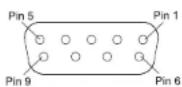
Figure 05—DB9 connector pin layout
RS232 DB9 Connector Pin Layout
-
N/C (no connection) 6. N/C
-
Data In (RXD) 7. N/C
-
Data Out (TXD) 8. N/C
-
N/C 9. N/C
-
Gnd
Typical RS232 settings are:
- 8 data bits, no parity and one stop bit
- Baud rate fixed at 115,200 bits per second
Wired IR Inputs
The IR Input allows an external IR receiver to be attached to the MX123. The Input is labeled IR IN. By attaching an IR receiver using a 3.5mm cable (See Figure 06), the MX123's Remote Control can
be used in another location without a line-of-sight to the MX123's front IR sensor. In this way, if ZONE 2 is another room, a Remote Control can be used to adjust the MX123.

Figure 06- IR 3.5mm connector
If using an external IR receiver for the MAIN ZONE in the same room as the MX123, you may wish to disable the front IR sensor, which also controls the MAIN ZONE. This will avoid potential timing issues of receiving the Remote Control's commands from two different Inputs. The front IR can be turned on/off by doing the following:
- Put the MX123 in STANDBY mode
- While pressing and holding the front panel ENTER and RETURN buttons, press the STANDBY button (a 3-button push)
- Use the Down Arrow on the Front Panel or Remote Control to navigate to the RC LOCK Off option to enable the front panel IR sensor or choose RC LOCK On to disable the front panel IR sensor. See Figure 07
- Pushing ENTER will make the selection and reboot the MX123

Figure 07 Setting the Remote Control Lock

Digital Inputs
There are four digital Inputs in the MX123:
- Two Toslink Optical Inputs
- Two Coaxial Digital audio Inputs
The two Coaxial Inputs are labeled:
• 1 (CBL/SAT)
• 2 (DVD)
The two Optical Inputs are labeled:
• 1 (TV AUDIO)
• 2 (CD)
The default names and assignments can be changed in setup.
The Optical Inputs require a Digital Optical Audio Cable Toslink Cable. The Coaxial Inputs use Digital Audio Coaxial Cables with male RCA type connectors.
Analog Audio Inputs
There are eight pairs of gold-plated RCA jacks. The left jack of the stereo pair is on top, and the right jack is below it. They are labeled as follows:
- PHONO
- TUNER
- CBL/SAT
- DVD
- BLU-RAY
- GAME
- CD
- MP
To the left of the PHONO jacks is a ground connection labeled GND for connecting a turntable's ground wire. The PHONO section of the MX123 is designed to work with Moving Magnet cartridges.
There is one pair of Balanced XLR Inputs. It is
labeled XLR BALANCED Input. Looking at the back of the unit, the Right Input is on the left and the Left Input is on the right.
There are eight gold plated RCA jacks designed for 7.1 Channel Input. They are located under the heading 7.1 CH Input. They are labeled:
- FL (Front Left)
- FR (Front Right)
• C (Center) - SUB (Subwoofer)
- SL (Surround Left)
- SR (Surround Right)
• SBL (Surround Back left)
• SBR (Surround Back Right)
All the Input names can be customized in the SETUP program, as well as hidden and restored. Hiding Inputs spares you from scrolling through unused Inputs.
AC Power
This connection is essential. Plug the female end of the supplied AC Power Cord into the AC connector located in the rear right corner of the MX123. Plug the male end of the AC Power Cord into a grounded and functioning AC outlet.
Balanced Audio Outputs
There are 15 male balanced XLR connections on the back of the MX123 to accommodate a wide variety of speaker configurations. Connect balanced XLR cables to the corresponding powered speakers or amplifiers. Here are the possible connections:
- FL (Front Left)
- FR (Front Right)
• C (Center) -
SW1 (Subwoofer 1)
-
SW2 (Subwoofer 2)
• SR (Surround Right) - SL (Surround Left)
• SBR (Surround Back Right)
• SBL (Surround Back left) - HR1 (Height Right 1)
- HL1 (Height Left 1)
• HR2 (Height Right 2) - HL2 (Height Left 2)
• HR3 (Height Right 3) - HL3 (Height Left 3)
This is all easier said than done. Setting up speakers for a surround setup takes planning, measuring and installation. Depending on your level of expertise and available time, you may wish to employ the services of your McIntosh dealer for expert setup of your system. Professional installation of in-ceiling speakers is particularly important due to gravity and the location above your head.
The number, types and locations of speakers are key elements in setting up the system. There is a multitude of possible configurations, and the MX123 is very flexible in its setup to adapt to many of these configurations.
Often surround setups are referred to by numbers for example 7.1.4 or 9.1.2. The first number refers to the number of traditional surround speakers (front, center and surround). The second number is the number of subwoofers that can be connected, and the third number refers to the number of in-ceiling or upward firing speakers in the setup.
The type of speaker (size and location) will be entered later during Speaker setup. The distance of the speaker from the listening location will be entered in the Audyssey® setup. Make note of this information.
At this stage, the connection from the MX123 to the various amplifiers and powered speakers should be made using quality balanced XLR cables.
Power Control (Trigger) Outputs
The MX123 has two Power Control Outputs or Triggers. Power Control enables power on/off signals to go to connected components so that other components can automatically power on (or off) as called for by the MX123. For example, you may want a DVD player and a certain monitor to power on when HDMI 1 Input is selected, or you may want all components to power off when powering off the MX123. For Setup instructions see “General Setup” on page 24.
Connect components using a 3.5mm stereo mini plug. See Figure 08.
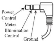
Figure 08- Power control (trigger) mini plug
Analog Audio Output
Two additional Zones labeled ZONE2 and ZONE3 can be fed analog signals using a pair of RCA cables for each Zone. The jacks are located under ANALOG AUDIO OUT on the right side of the rear of the MX123.
Data Out
The MX123 will convert IR Remote Control data to share with McIntosh components connected to the Data Ports. This will allow units that are out of range of an IR signal to receive commands.
To connect a McIntosh unit to a Data Port, use a 3.5mm stereo mini phone plug cable. See Figure 09.
When the MX123 A/V Processor is initially powered on (or after a Factory Reset- see page 31), the Setup assistant will appear on the Display and a connected monitor. After choosing a language, follow the guide's instructions to setup your Bluetooth/Wi-Fi Antenna Connection as well as Network Setup. For more information on Network Setup see "Network" on page 24.

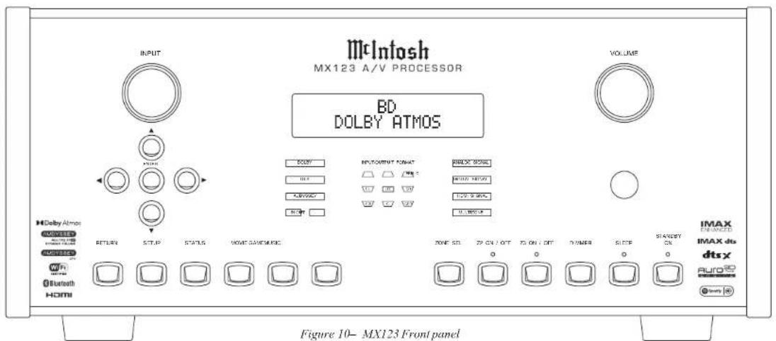
The Front Panel
The iconic front glass panel of the MX123 provides knobs and buttons to control the unit as well as an informational display and LED status lights that display the current mode.
Standby On
The red STANDBY ON button toggles the MX123 between on and standby mode. The STANDBY button will only work with AC Power connected (see "AC Power" on page 10). When the unit is in standby mode, it can also be toggled on/off using the Remote Control or the browser interface.
If Zone2 or 3 is on, those Zones will continue to be on. Those Zones can be toggled on and off using the ZONE ON / OFF buttons. See "Zone On/Off" on page 13.
The Input Knob
The Input Knob can be turned clockwise or counterclockwise to scroll through all the Inputs that are enabled in Setup. All Inputs are available by default.
The Volume Knob
Turn this knob clockwise to raise the volume and go the other way to make it quieter. A maximum volume of 70% is the factory default for each zone. The value of the Volume Limit can be set in the General Setup section for each Zone. Options are 60, 70, or 80 percent. You can defeat the Volume limit by choosing the "Off" option. A maximum volume prevents the MX123 from accidentally sending higher signals than your situation permits.
The Arrow and Enter Buttons
These buttons are used to navigate menu screens and selections in the Trim menus. The arrows allow scrolling up, down, left, and right when those are menu choices. The ENTER button accepts an option and the left button returns to the previous menu when a value is not being selected. If a value needs to be selected, the left and right arrows will scroll through the options. Push ENTER to select the chosen value.
Status
Repeated presses of the Front Panel or Remote Control STATUS Push-button will step through the type of incoming Audio Signal, the selected Input (along with type of A/V Connection) and audio processing mode.
Sound Mode Buttons
There are three buttons on the front panel that give you quick access to a selected sound/surround mode. The buttons are:
These buttons can also be accessed from the Remote Control with the added choice of PURE.
The following choices are available when selecting the MOVIE, MUSIC and GAME buttons:
- Stereo
• Dolby Audio – Dolby Surround - DTS Neural:X
• Auro-3D or DTS Virtual:X - Auro-2D Surround
- Multi Ch Stereo
For Auro-3D to be available, Front Height speakers must be enabled. DTS Virtual:X is available if no Height, Top or Dolby Enabled speakers are used.
Choosing a button will switch to the last mode selected. The mode can be switched using the up ▲ and down ▼ arrows.
The PURE button on the remote offers the following modes:
- Direct- This mode plays back audio as recorded in the source
- Pure Direct- This mode plays back an even higher quality sound than the “Direct” mode. In order to further improve sound quality, the display indicator circuit of the main body will be disabled (display will go off), and the analog video Input/Output switcher and processor is disabled
• Auto- In this mode, the type of digital signal
Input, such as Dolby Digital, Dolby TrueHD, Dolby Digital Plus, Dolby Digital EX, Dolby Atmos, DTS, DTS-HD, DTS:X, DTS-ES, or PCM (multi-channel) is detected, and the playback mode switches automatically to the corresponding mode. If the Input signal is analog or PCM (2-channel), stereo playback is used. For Dolby Digital or DTS, the music is played back according to the respective channel number
The display screen, if on, will leave the Sound Mode screen after 5 seconds.
Zone Select
The ZONE SEL button allows you to adjust the volume and input of Zone2 and Zone3 using the front panel knobs. Pressing the ZONE SEL button will toggle between Zone2 and Zone3. Stop at the Zone in which you wish to change the volume. After 5 seconds of not adjusting the volume for the chosen zone, the VOLUME knob will default to Main Zone.
Zone On/Off
The MX123 has three Zones. Zone1 is called the Main Zone and is the default for the display. Analog stereo signals can be sent to Zone2 and Zone3. The Z2 ON / OFF and Z3 ON / OFF buttons toggle these zones on and off.
If you push the STANDBY ON button to power off the unit, Zone2 and/or Zone3 will remain on if they are currently on. To shut off these zones, use their respective Z2 ON / OFF or Z3 ON / OFF buttons. These buttons can be used to turn on the desired zone if the MX123 is in standby mode.
If the Main Zone is off and one or both of the other Zones are on, this information will appear on the
display.
Dimmer
Pressing the DIMMER button cycles through 4 levels of Display brightness:
- Bright (Default): Normal display brightness
• Dim: Reduced display brightness
• Dark: Very low display brightness - Off: Turns the display off
Sleep Timer
The SLEEP button allows you to set a sleep timer between 10 minutes and 120 minutes for the Main Zone. Pressing the button will set the timer in 10 minute increments to the maximum or set the Sleep Timer to off. When a Sleep Timer is set for the Main Zone, the red LED above the SLEEP button will illuminate.
When the MX123 goes to sleep, the Zone2 and Zone3 will remain on. To set a Sleep Timer for these zones, use the SLEEP button on the Remote Control. Set the Remote Control to the desired zone using the ZONE SELECT button. The Remote Control's SLEEP button will function the same as the front panel's SLEEP button. Each Zone can have a separate sleep timer set.
Changing GUI Language/Video Format
By holding both the STATUS button and the ZONE SEL button simultaneously for three seconds, the following setup option can be changed using the Arrow Buttons:

| Setting | Options |
| Use up anddown to select | Use left ▲nd right ▲tselect |
| GUI English, French or Spanish | |
| Video Format NTSC or PAL | |
| 4K Format Standard or Enhanced | |
LED Channel Status Indicators
The yellow LEDs, in the center of the MX123 front panel, provide a visual display of the status of the main zone's signal for either Input or Output.
The Left Column Displays:
• DOLBY
• DTS
• AUDYSSEY
• IN OUT
Either IN or OUT will be lit depending on what has been chosen in Setup for the Front Display setting. (See "Front Display" under "General Setup" on page 2425.) Other features will be lit if currently enabled for the current Input.
The middle section shows speaker channels that are active. Here are the channel abbreviations used:
- FL-Front Left
• C- Center - FR-Front Right
- SL-Surround Left
• LFE- Low Frequency Effects - SR- Surround Right
• SBL- Surround Back Left
• S- Surround (RS + LS)
• SBR- Surround Back Right
Channels currently used will be lit.
The right display has the following information:
• ANALOG SIGNAL
• DIGITAL SIGNAL
- HDMI SIGNAL
- MULTIZONE
The Main Zone's signal type will be lit. If Zone2 and/or 3 is active, the MULTIZONE will light. Pushing the INFO button on the MX123 Remote Control will show the following information on an attached monitor:
- SOURCE
- SOUND
• SIGNAL
• INPUT SIGNAL (CHANNELS)
• ACTIVE SPEAKERS
The indicators for Input SIGNAL include the speaker channels listed above plus:
- FHL-Front Height Left
• FHR- Front Height Right - FWL-Front Wide Left
- FWR- Front Wide Right
- EXT-extension channel
The extension channel will light when a channel other than the listed ones is part of the Input.
Setup
Pushing the SETUP button will bring up the Setup Menu on an attached monitor. When in setup mode, the Display will show the current level and option (See Figure 11). You can navigate using the Display, but an attached monitor is easier.
To exit setup mode, push the SETUP button again.
\*SETUP MENU Audio
Figure 11—Display in Setup Mode
The Setup Menu
The factory default settings will allow you to use the MX123 as soon as you properly connect your components. However, sooner or later, you may wish to fine tune your system. You can utilize the MX123's robust setup program for customization and optimization of your Audio Visual environment. MX123 setup can be performed by using either the SETUP button on the Front Panel or the Remote Control and using an attached monitor (local setup), or through a web browser on a computer if the MX123 is connected to your network. See Figure 12.

Figure 12- Browser Setup Menu
The procedures and screens are essentially the same for all methods. The availability of a mouse and a keyboard in the browser method may be easier to navigate than using the arrow buttons on the Front Panel or Remote Control that are used for local setup. You can choose to use the Front Panel Display to navigate setup, but the limited screen size would make this the least desirable setup method.
To use a browser to navigate setup, type the IP address for the MX123 in the address bar of your browser. You can find the IP address under the Information submenu under the Network section of
setup (see "Network" on page 24).
Setup has the following sub-menus:
- Audio
- Video
- Inputs
- Speakers
- Network
- General
In this manual, sub menus are denoted in the style "Setup Menu>General>Front Display>Dimmer" which means from the "SETUP Menu" choose "General" and then choose "Front Display" and then "Dimmer".
Browser Security Warning
When you attempt to load the Setup Menu on a browser, you will likely see some version of a Warning that you are about to experience a Potential Security Risk or some computer attack. Do not worry about this scary warning generated from your browser. It is a result of the MX123 using the more secure HTTPS connection and the browser is not recognizing the local certificate. The connection is actually more secure than past software interfaces by using this secure connection. To use this more secure connection, you must first proceed using your browser's Advanced setting options. Choose the advanced option or "continue anyway" option to proceed to the Setup Menu page against all your browser's warnings. The advanced options will be slightly different depending on your browser, but all of them will allow the choice to continue the Setup Menu page. After initially bypassing this screen, your browser should open this page in the future without hesitation.

Your connection is not private
Attackers might be trying to steal your information from 192.168.1.110 (for example, passwords, messages, or credit cards). Learn more
NET:ERR_CERT_AUTHORITY,INVALID
□ Help improve Safe Browsing by sending some system information and page content to Google Privacy policy


Figure 13- Sample Browser Warning screen
Speakers- Setup Menu
The Speakers Setup menu has two main parts:
- Audyssey ®
- Manual Setup
Audyssey® Setup is detailed starting with "Audyssey® Setup" on page 28. Audyssey® will provide much of the information that can be set in the Manual Setup portion. The Manual Setup allows you to tell the MX123 what your speaker setup and preferences are. We will begin by covering the Manual Setup.
Amp Assign
Setup Menu>Speakers>Manual Setup>Amp Assign
In Amp Assign, you select how to use the preamplifier section of the MX123. In the Amp Assign section of Setup, you can tell the MX123 what speaker setup scheme you will be using. This affects what speaker types are available in the Manual Setup for speakers explained in the next section.
The default setting is 13.1 channels which will provide great flexibility in the speaker setup. Some
available options are dependent on other setup choices. Here are all the available setup options for Amp Assign:
| SettingUse up ▲down▼ to select | OptionsUse left ◄nd right t▶ select |
| Layout 13.1 channel | 11.1 channel (Bi-Amp)11.1 channel + Front BPre-out for Bi-Amp andFront B options:Surround BackHeight 2Height 3 |
| Floor -Layout 5 channel | 5 channel & FW5 channel & SB |
| Height Sp None | 2 channel4 channel5 channel6 channel7 channel8 channel |
| Dolby Sp None | 2 channel4 channel |
| Height -Layout Front DolbyLayout | Surround DolbyBack Dolby |
| Height -Front Layout | Front HeightFront & Center Height |
| Height -Middle Layout | Top SurroundSurr. Height & Top Surround |

| Setting | Options |
| Use up ▲down▼ to select | Use left ◁nd right t▶ select |
| Height -Rear Layout | Top RearRear HeightSurround HeightTop MiddleTop Rear |
Speaker Types and Positions
The following table and diagrams show possibilities for speaker setup as well as the terms used to describe them.
You will need the number and types of speakers as well as the distance of each from the main listening position for the Speaker Configuration in Setup.
| FL/FR (Front speaker Left/Right) | FRONT Left and Right speakers should be an equal distance from the main listening position. The distance between each speaker and your TV should also be about the same. |
| C (Center) The | CENTER speaker should be between the Front speakers and above or below your TV. |
| SL/SR(Surround speaker Left/Right) | The SURROUND Left and Right speakers should be an equal distance from the left and right sides of the main listening position. If you don’t have Surround Back speakers, move the surround speakers slightly behind your listening position. |
| FWL/FWR(Front Wide speaker Left/Right) | The FRONT WIDE Left and Right speakers should be outside of the front Left and Right speakers so that there is an equal distance between all Front speakers. |
| SBL/SBR(Surround Back Left/Right) | Place the SURROUND BACK Left and Right speakers an equal distance from the main listening position and directly behind the main listening position. When using a single Surround Back speaker (SB), place it directly behind the listening position. |
| SW 1/2(Subwoofer) | Place the SUBWOOFER at a convenient location near the Front speakers. If you have two Subwoofers, place them asymmetrically across the front of your room. |
| FDL/FDR(Front Dolby speaker Lcfl/Right) | Place the FRONT Dolby Atmos Enabled speaker on the Front speaker. For a Dolby Atmos Enabled integrated with a Front speaker, place the Dolby Atmos Enabled speaker instead of the Front speaker. |
| SDL/SDR(Surround Dolby speaker Lcfl/Right) | Place the SURROUND Dolby Atmos Enabled speaker on the Surround speaker. For a Dolby Atmos Enabled speaker integrated with a Surround speaker, place the Dolby Atmos Enabled speaker instead of the Surround speaker. |
| BDL/BDR(Back Dolby speaker Left/Right) | Place the BACK Dolby Atmos Enabled speaker on the surround back speaker. For a Dolby Atmos Enabled speaker integrated with a Surround Back speaker, place the Dolby Atmos Enabled speaker instead of the Surround Back speaker. |
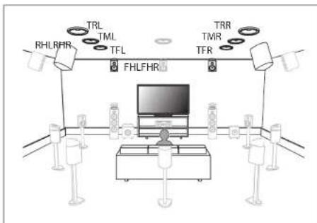
| FHL/FHR(Front Height speaker Left/Right) | FRONT HEIGHT Left and Right speakers are mounted directly above the Front speakers. Mount them as close to the ceiling as possible and aim them towards the main listening position. |
| TFL/TFR(Top Front speaker Left/Right) | Mount the TOP FRONT Left and Right speakers on the ceiling slightly in front of your main listening position and align with the Left and Right Front speakers. |
| TML/TMR(Top Middle speaker Left/Right) | Mount the TOP MIDDLE Left and Right speakers directly above the main listening position and align with the Left and Right Front speakers. |
| TRL/TRR(Top Rear speaker Left/Right) | Mount the TOP REAR Left and Right speakers on the ceiling slightly behind your main listening position and align with the Left and Right Front speakers. |
| RHL/RHR(Rear Height speaker Left/Right) | Place the REAR HEIGHT Left and Right speakers directly behind the main listening position. Mount them as close to the ceiling as possible and align with the Left and Right Front speakers. |
| SHL/SHR(Surround Height speaker Left/Right) | Place the SURROUND HEIGHT Left and Right speakers directly above the Surround speakers. |
| CH (Center Height speaker) | Place the CENTER HEIGHT speaker directly above the Center speaker. Mount it as close to the ceiling as possible and aim it towards the main listening position. |
| TS (Top Surround speaker) | Place the TOP SURROUND speaker directly above the main listening position and align with the Center channel speaker. |
Note that the Amp Assign default setting of 13.1 is recommended for 5.1, 7.1, 9.1 and of course 13.1 playback. 11.1 channel playback should be used for 11.1 channel Bi-amp and 11.1 channel second pair of front speakers playback.
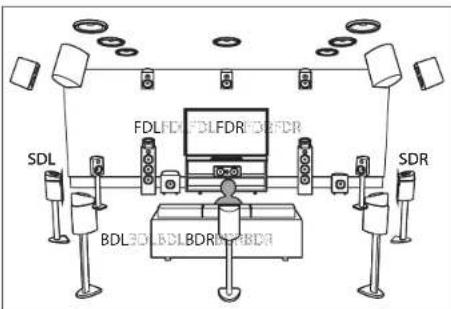
Figure 14—Speaker Positions and abbreviations

flowchart
graph TD
    A["SHL"] --> B["TS"]
    B --> C["CH"]
    C --> D["SHR"]
    D --> E["Control Panel"]
    style A fill:#f9f,stroke:#333
    style B fill:#ccf,stroke:#333
    style C fill:#cfc,stroke:#333
    style D fill:#fcc,stroke:#333
    style E fill:#ffc,stroke:#333


Figure 15-Auro-3D layout example
The above example is a combination of 5.1 channel speakers with Front Height/Surround Height/Center Height/Top Surround speakers.
For the best Auro-3D experience Surround Height speakers are recommended, however you may substitute Rear Height speakers from a Dolby Atmos speaker setup in place of Surround Height speakers.
You will need at least Front Heights for Auro-3D to be an option.
Speaker Configuration
Setup Menu>Speakers>Manual Setup>Speaker Config
Here is where you tell the MX123 what type of speakers are connected. The available speaker categories are based on the settings in Amp Assign (See "Speakers- Setup Menu" on page 15).
Speakers are defined as Large or Small (or None). A Large Speaker is a full-range speaker. (Technically, a speaker able to reproduce bass frequencies down to 35Hz within -3dB of the midrange frequencies.) If it is not Large, then it is Small. If it doesn't exist, choose None.

natural_image
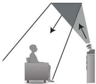
Illustration of a person sitting at a desk receiving an inverted angle from a lamp, with no visible text or symbols.Figure 16—Dolby Atmos Enabled speakers
Dolby Atmos Enabled speakers reflect the sound off the ceiling to allow the sound to come from over your head by using a special upward-pointing speaker that is placed on the floor. See Figure 16. You can enjoy the Dolby Atmos 3D sound even in an environment where speakers cannot be installed on the ceiling.
| Speaker Options |
| Front Large / Small |
| Center Large / Small / None |
| Subwoofer None/ 1 spkr / 2 spkrs |
| Surround Large / Small / None |
| Surr. Back Large / Small / None1 spkr / 2 spkrs |
| Front Wide Large / Small / None |
| Front Height Large / Small / None |
| Rear Height Large / Small / None |
| Center Height Large / Small / None |
| Top Surround Large / Small / None |
Speaker Distances
Setup Menu>Speakers>Manual Setup>Distances
In this section, the distances of the speakers from the main listening position should be entered. This will aid in perfecting 3D imaging. A laser pointer may be a helpful tool to measure the distance from a speaker to the main listening position. In the Distances submenu, there are two menu settings, Unit and Step, that each have two options. For Unit, you can choose Feet or Meters as the unit of measurement.
Step sets the value of each button push for setting the distances. The Step values are 0.1 or 1. You can use the larger Step value to Input the rough measurements and then the smaller Step value to fine tune. This may save you many button pushes.
Speaker Levels
Setup Menu>Speakers>Manual Setup>Levels
Selecting Levels allows you to make changes to the Output levels of each speaker -12.0dB to +12.0dB. These set levels are reflected in all sound modes. Select Test Tone Start. You will then be able to play a Test Tone on all available speakers and adjust the relative Output levels. You can choose Set Defaults on the Test Tone Start screen to set all levels to factory defaults (0.0dB).
Crossovers
Setup Menu>Speakers>Manual Setup>Crossovers
Crossovers can be set when the "Subwoofer Mode"
setting is "LFE+Main", or when you have a speaker that is set to "Small".
The default crossover frequency is "80Hz", which will work best with the widest variety of speakers. We recommend setting to a higher frequency when small speakers are used. For example, set to "250Hz" when the frequency range of the speakers is 250Hz to 20kHz.
Sound below the crossover frequency is cut off from the Output to "Small" speakers and is outputted to the subwoofer or front speakers.
You can choose Individual or All. The Individual option will allow each available speaker's crossover frequency to be set individually. The All option will globally set the Crossover Frequency to the chosen value. Available values are:
40 Hz / 60 Hz / 80 Hz / 90 Hz / 100 Hz / 110 Hz / 120 Hz / 150 Hz / 200 Hz / 250 Hz
Bass
Setup Menu>Speakers>Manual Setup>Bass
The Subwoofer Mode can be set for:
• LFE (Low Frequency Effects) which would provide only the LFE channel
• LFE+Main which would include the Main channel as well as the LFE channel
LPF for LFE allows the LPF (Low Pass Filter) setting for the Subwoofer Mode to be changed. The options are:
80 Hz / 90 Hz / 100 Hz / 110 Hz / 120 Hz / 150 Hz / 200 Hz / 250 Hz
Front Speaker
Setup Menu>Speakers>Manual Setup>Front Speaker
If Amp Assign is set to the Front B option, the Front Speaker setting will be available. See Layout under Amp Assign on page 15.
Options for the Front Speaker setting are: A / B / A+B.
2 Channel Playback
Setup Menu>Speakers>Manual Setup>2ch Playback
2 Channel Playback can be set automatically or manually. Here are the setup options:
| 2ch Setting Options | |
| Setting Manual / Automatic | |
| Front Small / Large | |
| Subwoofer Yes / No | |
| SW (Subwoofer) Mode | LFE / LFE+Main |
| Crossover 40/60/80/90/1 | 100/110/120/150/200/250 Hz |
| Distance FL 0 feet to 32 | feet0 meters to 9.6 meters |
| Distance FR 0 feet to 32 | feet0 meters to 9.6 meters |
| Level FL -12 dB to +12 | dB |
| Level FR -12 dB to +12 | dB |
Audio- Setup Menu
Setup Menu>Audio
Depending on your speaker configuration and options, the following settings may be adjusted in the Audio Setup section:
- Subwoofer Level Adjust
- Bass Sync
- DFR
- Audio Delay
- Volume
- Audyssey
- Graphic EQ
Subwoofer Level Adjust
Setup Menu>Audio>Subwoofer Level Adjust
This setting allows you to adjust the level of Subwoofer 1 and the level of Subwoofer 2 (if they exist) from -12dB to +12dB in .5dB increments.
Bass Sync
Setup Menu>Audio>Bass Sync
For contents recorded in multi-channel such as Blu-ray discs, the recorded Low Frequency Effects (LFE) may be out of sync and delayed. This function allows you to correct the delay with an adjustment of 0 ms to 16 ms.
Sound Parameter
Setup Menu>Audio>Sound Parameter
This allows Cinema EQ to be turned On or Off. Cinema EQ softens the treble range of a movie soundtrack using Dynamic Compression and Dialogue Normalization for better understanding of movie dialogue.
The Sound Parameter option is only available for the current sound mode if it applies. Settings are saved for each individual sound mode.
DFR
Setup Menu>Audio>DFR
DFR, which stands for Dynamic Frequency Restorer, restores compressed audio formats to near their original sound before compression. DFR will work on compressed audio formats such as MP3, WMA, and MPEG4 AAC. The options for the DFR setting are:
- OFF- DFR is disabled
- High- Optimized mode for compressed sources with very weak highs (64 kbps and under)
- Medium- Applies suitable bass and treble boost for compressed sources (96 kbps and under)
- Low- Optimized mode for compressed sources with normal highs (96 kbps and over)
Audio Delay
Setup Menu>Audio>Audio Delay
Audio Delay compensates for incorrect timing between video and audio. When Auto Lip Sync is set to On, the timing difference will be automatically corrected with compatible TVs. The Adjust option allows you to manually adjust the delay correction from the Default of 0 ms up to 500 ms.
Volume Setup
Setup Menu>Audio>Volume
There are four variables that can be changed in the Volume setup:
- Scale- There are two choices for how to display the Volume. The default is a scale of 0 to 98. The second option is to show the decibel (dB) level. The decibel scale is from -79.5dB to 18dB

- Limit-There are four options for setting a maximum allowable volume level- Off, 60 (-20dB), 70 (110dB), and 80 (0dB). Setting a Volume Limit can protect equipment and/or ears from unintended extreme volume
- Power On Level- You can set the Volume level which the MX123 will power on to. Choices are Mute, Last (last volume used) or any other available volume level from 1 (-79dB) to the maximum volume or the Volume Limit if one is set
- Mute- You can set what volume reduction occurs when the MUTE button on the Remote Control is pushed. Options are Full, -40dB and -20dB
Audyssey® Options Menu
Setup Menu>Audio>Audyssey ^®
After Audyssey® Setup (see “Audyssey® Setup” on page 28) has been performed, the following setup options may be available:
- MultEQ XT32
- Dynamic EQ
- Audyssey ^® LFC
MultEQ XT32 optimizes the frequency response of your speakers. It compensates for both time and frequency characteristics of the listening area based on Audyssey® Setup. The default setting is Reference. Reference provides a compensation curve that is optimized for movies with a slight roll off at the higher frequencies. The Flat setting is optimized for small rooms where your listening position is closer to the speakers. Keep in mind that many movie soundtracks are optimized for large theaters. The options in the Audyssey® setup section help maintain the theater experience in smaller
spaces as well as at lower volumes. The third MultEQ XT32 choice is Off which will turn off the MultEQ XT32 equalization.
Dynamic EQ solves the problem of deteriorating sound quality as volume is decreased by taking into account human perception and room acoustics. Dynamic EQ can be turned On and Off. If it is On (the default), the Reference Level Offset option appears. Audyssey ^8 Dynamic EQ ^9 is referenced to the standard film mix level. It makes adjustments to maintain the reference response and surround envelopment when the volume is turned down from 0dB. However, film reference level is not always used in music or other non-film content. Dynamic EQ Reference Level Offset provides three offsets from the film level reference (5dB, 10dB, and 15dB) that can be selected when the mix level of the content is not within the standard.
| Offset Content | |
| 0dB (Default) Optimized for movies | |
| 5dB Select this setting for content that has a very wide dynamic range, such as classical music | |
| 10dB Select this setting for jazz or other music that has a wider dynamic range. This setting should also be selected for TV content as that is usually mixed at 10dB below film reference | |
| 15dB Select this setting for pop/rock music or other program material that is mixed at very high listening levels and has a compressed dynamic range |
Dynamic Volume solves the problem of large variations in volume level between TV, movies and other content (between quiet passages and loud
passages, etc.) by automatically adjusting to the user's preferred volume setting.
The settings available for Dynamic Volume ranging from least adjustment are: Off, Light, Medium and Heavy. Medium is the default set if Dynamic Volume is set to Yes in Audyssey® Setup.
Audyssey® LFC™ cuts the excessive low frequencies that plague your neighbor, but without removing bass perception in the room where the home theater system is operating. This is accomplished by dynamically monitoring low frequencies and reducing the “offending” ones. Audyssey® LFC™ can be turned On and Off. If On, the Containment Amount may be set between 1 and 7. The default is 4. The higher the setting the greater the containment of low frequencies.
Video- Setup Menu
Setup Menu>Video
The Video Setup section has the following submenus:
- Picture Adjust
- HDMI Setup
- Output Settings
- Analog Video Out
- On Screen Display
- 4K/8K Signal Format
- TV Format
Picture Adjust
Setup Menu>Video>Picture Adjust
Picture Adjust allows you to select a Picture Mode that best matches the video content to the viewing environment. Picture Mode options are:
- Off- No picture adjustment
- Standard- best choice for most living room environments
- Movie- best suited for watching movies in a darkened room (such as a theater room)
• Vivid-brightens images, suitable for gaming - Streaming- designed for watching low bit video sources
- Custom- allows manual picture quality adjustments. Contrast, Brightness, and Saturation can be adjusted on a scale of -50 to +50. Video Noise Reduction can be changed from its default of Off to Low, Medium or High. Enhancer emphasizes picture contours and is set on a scale from a default of 0 to 12
HDMI Setup
Setup Menu>Video>HDMI Setup
HDMI Setup provides options for HDMI Audio Out, HDMI Pass Through and HDMI Control settings:
- HDMI Audio Out setting is available only when the HDMI Control is set to off. This setting channels the HDMI Audio Output HDMI to either AVP, which would be speakers controlled through the MX123, or TV which would use the TV's speakers
- Vertical Stretch- The abiltiy to stretch the video signals vertically can be toggled On or Off
- HDMI Pass Through can be toggled On and Off. HDMI Pass Through transmits the selected HDMI Input through this unit's HDMI Output while the unit is in standby power mode. If HDMI Pass Through is On, a Pass Through Source can be selected. Source choices are the seven HDMI Inputs
listed under their assigned names. The default source is CBL/SAT. If you choose Last as the source, the last used HDMI source will be the one used in Standby mode. RC Source Select tells the MX123 how to respond, when in Standby Mode, to a Source command from the Remote Control. If the default Power On + Source option is selected, pressing a source button on the Remote Control will turn the MX123 on and select that Input source. With the Source Select Only option, the HDMI Input will change, but the MX123 will remain in Standby
- HDMI Control can be toggled On and Off to allow a connected CEC compatible TV connected to HDMI MONITOR 1 to send control functions over the HDMI cable. CEC (Consumer Electronics Control) is an addition to the HDMI standard which allows control signals from one device to communicate with another device via an HDMI cable connection. If you change HDMI Control settings, reset power to connected devices. Make sure CEC is enabled on all devices
The table below shows additional options for HDMI Control:
| Options HDMI | Control On | HDMI Control Off |
| ARC (Audio Return Channel) | On On/Off* | (*Default) |
| TV Audio Switching-automatically select a TV Audio Input when receiving a command from the TV | On/Off Not | Available |
| Options HDMI | Control On | HDMI Control Off |
| Power Off Control-MX123 will enter Standby Mode when a connected TV is turned off regardless of Input source for All, and for HDMI, COMP and VIDEO Input sources with Video selected | All/Video/Off | Not Available |
| Power Saving- use Power Saving functions when enabled | On/Off Not | Available |
Output Settings
Setup Menu>Video>Output Settings
In this section, adjustments can be made to the video Output.
HDMI Video Output
Setup Menu>Video>Output Settings> HDMI Video Output
HDMI Video Output selects the HDMI monitor to be used. Options are:
| Auto (Dual) | The presence of a TV connected to the HDMI MONITOR 1 or HDMI MONITOR 2 connector is detected automatically, and that TV connection is used |
| Monitor 1 A | TV connected to the HDMI MONITOR 1 connector is always used |

| Monitor 2 A | TV connected to the HDMI MONITOR 2 connector is always used |
Video Mode
Setup Menu>Video>Output Settings>Video Mode
Video Mode configures the processing method to match the type of video content. Options are:
| Auto (Default) | Process video automatically based on the HDMI content information |
| Game Always | process video for game content. Minimize the video delay when the video is delayed compared to the button operations on the controller of the game console |
| Movie Perform | image processing that is suitable for contents other than games |
If Video Mode is set to Auto, the mode is switched according to the Input contents.
Video Conversion
Setup Menu>Video>Output Settings>Video Conversion
Video Conversion enables the conversion of non-HDMI sources to the HDMI Output. Video signals will be converted to the proper monitor Output format.
Options are On and Off. Off will disable Video Conversion. If disabled, on-screen graphics, such as the volume bar, may not be displayed over the video
signal.
When Video Conversion is enabled (On), the following settings are available:
i/p Scaler sets the video Input signal to be subjected to i/p Scaler processing. i/p Scaler will convert the resolution of the Input video signal to the value set in Resolution (see Resolution below). i/p Scaler options are:
| Analog Use | i/p (interlace-to-progressive) scaler function for analog video signals |
| Analog & HDMI | Use i/p Scaler function for analog and HDMI video signal |
| Off Do not use | i/p Scaler function |
If i/p Scaler is enabled the following options for these settings will be available:
Resolution can be set to Auto which will automatically select the resolution based on the attached monitor's capabilities. The following resolutions can be manually selected: 480p/576p, 1080i, 720p, 1080p, 1080p:24Hz, and 4K. These settings can be set for analog resolution and HDMI resolution independently.
Sharpness can be turned On and Off. Off is the default. The video enhancer sharpness feature provides image edge contouring which is optimized for converting lower resolution standard definition video to 4K.
Progressive Mode sets an appropriate progressive conversion mode for the source video signal. Options are:
| Auto (Default) The video | signal is automatically detected and the appropriate mode is set |
| Video Mode suitable for | video playback |
| Video and Film Mode su | table for video and 30-frame film material playback |
Aspect Ratio can be set for the default 16:9 Output or 4:3 Output with black bars on the sides of a 16:9 screen (except for 480p/576p Output). Aspect Ratio is expressed in terms of width:height.
Analog Video Out
Setup Menu>Video>Video Out
Analog Video Out allows you to select which zone receives video and component video Output. Options are:
| Component Video Output | Main ZoneZone2Zone3 |
| Video Output Main Zone | Zone3 |
On Screen Display
Setup Menu>Video>On Screen Display
On Screen Display preferences can be selected as follows:
| Volume- display of volume level | Bottom (default)TopOff |
| Info- temporarily displays status of Input source when switched | On (default)Off |
| Now Playing- on-screen display for Online Music Source | Always on (default)Auto Off- show for 30 seconds |
4K/8K Signal Format
Setup Menu>Video>4K Signal Format
There are three options for 4K/8K playback when connected to an HDMI 4K or 8K signal compatible device.
| Standard Select if your TV and playback devices support standard 4K 60p 4:2:0 8 bit video signals | |
| Enhanced (default) | Select if your TV, playback devices, and cables support high quality 4K 60p 4:4:4, 4:2:2 or 4K 60p 4:2:0 10 bit video signals |
| 8K Enhanced | Select if your TV, playback devices, and cables support high quality 8K 60p or 4K 120p video signals. |
Use of a Ultra High Speed HDMI cable is recommended for Enhanced playback (see "HDMI" on page 9). Make sure the connected 4K/8K device's settings are properly set.
TV Format
Setup Menu>Video>TV Format
There are two options for the video signal Output format to be sent to your TV:
- NTSC (Default)
PAL
NTSC is the video standard used in North America and most of South America. PAL is commonly used in most of Western Europe, China, India, Australia, and most of Africa.
Inputs Setup Menu
Setup Menu>Inputs
The MX123 will work without making any changes to the Inputs. The following Input options can be
customized:
- Input Assign
- Source Rename
- Hide Sources
- Source Level
- Input Select
Input Assign
Setup Menu>Inputs>Input Assign
Different Input Sources can be assigned to different Input connectors. The default assignments are as follows:
| Input Source | Input Connector | ||||
| HDMI | DIGITAL | ANALOG | COMP | VIDEO | |
| CBL/SAT | 1 | 0AX1 | 1 | 1 | |
| DVD | 2 | 0AX2 | 2 | 2 | |
| Blu-ray | 3 | - | 3 | ||
| Game | 4 | - | 4 | ||
| Media Player | 5 | - | - | ||
| TV Audio | - | OPT1 | - | - | |
| AUX | 7(8K) | - | - | - | |
| CD | 6 | OPT2 | 5 | - | - |
Use the arrows to scroll up ▲, down▼, left ◀, and right ▶ in the Input Assign table. On a cell you wish to change, press ENTER. Use the left ◀ and right ▶ arrows to scroll through available values. Press ENTER to make your choice.
Only available options will be choices. For example, only OPT1, OPT2, COAX1 and COAX2 are available for Digital Inputs. When an HDMI channel is selected, it will be removed from its previous assignment. Also, when HDMI Control or ARC is set to On in the menu, HDMI cannot be assigned to
TV Audio.
Source Rename
Setup Menu>Inputs>Source Rename
All Input source's names can be customized. The new name will appear whenever that Input is displayed.
The Set Defaults button will return ALL names back to their original names.
Hide Sources
Setup Menu>Inputs>Hide Sources
You can hide any unused Input from being displayed. This will save you the trouble of scrolling through them. Select Hide for any Input you wish to hide. Selecting Show, which is the default, will make the Input visible once again.
Source Level
Setup Menu>Inputs>Source Level
Difference in Input volumes may be corrected with Source Level. Analog Inputs and Digital Inputs can each be adjust from -12dB to +12dB. The adjustment is saved for the currently selected Input source.
Input Select
Setup Menu>Inputs Animation Select
Input Select allows you to set the audio Input mode of each Input source. The Input modes available for selection may vary depending on the Input source.
Options for Input Mode are:
- Auto- this default mode is recommended for most circumstances. It will automatically detect an Input signal and perform playback accordingly
• HDMI- plays only HDMI signals

• Digital-plays only digital audio Input
- Analog-plays only analog audio Input
- 7.1CH IN-only plays signals from the 7.1CH Input connector
Network
Setup Menu>Network
The MX123 A/V Processor can be connected to your home network through a wired or wireless LAN connection. The Network section of Setup allows you to configure your network settings.
The Network menu has the following submenus:
• Information
- Connection
- Settings
• Network Control
- Friendly Name
• Diagnostics
Information displays the following information: Friendly Name, Connection, SSID, DHCP status, IP Address, MAC Address (Ethernet), MAC Address (Wi-Fi) as well as a graphic representing Wi-Fi signal strength.
Connection has two options: Wired (Ethernet) and Wireless (Wi-Fi). Wireless is the default. Choosing the Wi-Fi option will bring up a Wi-Fi Setup button. There will be four options for connecting to a Wi-Fi network:
- Scan Networks- select from a list of discovered networks. Choose Rescan to refresh the list. Choose a network, then enter the password and select OK
- Use iOS Device- if you have an Apple device (iPhone, iPod, iPad) running iOS 7 or later, launch the settings app on your device and select "Wi-Fi" and then choose "McIntosh
- Scan Networks- select from a list of discovered networks. Choose Rescan to refresh the list. Choose a network, then enter the password and select OK
- Use iOS Device- if you have an Apple device (iPhone, iPod, iPad) running iOS 7 or later, launch the settings app on your device and select "Wi-Fi" and then choose "McIntosh
MX123" under SET UP NEW AIRPLAY SPEAKER. Follow your device's instructions
- WPS Router- Press the WPS switch on your router. Press Connect on the WPS Router submenu screen within two minutes
- Manual- allows you to manually enter the SSID, Security encryption method and password for your wireless network. Select Connect when done
Settings configures the IP address of the MX123. The default setting is DHCP On. In most cases, the MX123 will receive the required information from the router.
If you switch DHCP to Off, you can manually enter the IP address information which is handy if you want to use a particular unchanging IP address. You will need the following information to manually set the IP address:
- IP address
- Subnet Mask address (Typically 255.255.255.0)
- Default Gateway address (Address of your router)
- DNS address
Network Control gives you the option of suspending the network function when the MX123 is in standby mode. This will conserve some power in standby mode, but the MX123 can not be woken from a network controller when Off In Standby is selected.
The default setting for Network Control is Always On. This allows the MX123 to be operable with a network compatible controller.
Friendly Name allows you to select what name will be displayed for the MX123 on your network. Options are: Home Theater / Living Room / Family Room / Guest Room / Kitchen / Dining Room /
Master Bedroom / Bedroom / Den / Office / Other. Choosing Other will allow you to Input a custom name.
Diagnostics will test the network connection and report any errors.
General Setup
Setup Menu>General
The General Menu contains the following submenus to make changes to various settings:
- Language
- ZONE2 Setup
- ZONE3 Setup
- Zone Rename
- Quick Select Names
- Trigger Out 1
- Trigger Out 2
- Auto Standby
- Front Display
- Firmware
- Information
- Save & Load
- Setup Lock
Language allows you to set the language for the display menus. The default is English, but the language can be changed to French or Spanish.
Zone2 and Zone3 Setup has the following options:
| Menu Item Zone Settings | |
| Bass -10dB to + | 0dB (Default 0dB) |
| Treble -10dB to - | 10dB (Default 0dB) |
| High Pass Filter (HPF) attenuates low frequencies to reduce distortion | On / Off (Default) |
| Lch Level (Left channel Output Level) | -12dB to +12dB (Default 0dB) |
| Rch Level (Right channel Output Level) | -12dB to +12dB (Default 0dB) |
| Channel Stereo (Default) / Mono | |
| HDMI Audio (Zone2 only) | Through (Default- HDMI audio signal passed to ZONE2 device) / PCM (HDMI is converted to PCM for ZONE2) |
| Volume Level Variable / Fixed at a set volume of 1 to 98 (-79dB to 18dB) | |
| Volume Limit (if Volume Level is Variable) | Off (no max) / 60 (-20dB) /70 (-10dB) / 80 (0dB)-sets a maximum allowable volume |
| Power On Volume (if Volume Level is Variable) | Initial power on volume settings: Last (default) / Mute / 1 to 98 (-79dB to 18dB). |
| Mutc Level Full (default) / 40dB / -20dB | |
Zone Rename allows you to set custom names of up to 10 characters for each zone. Choosing the Set Defaults button will return to factory default names.
Quick Select Names allows you to set custom names for the four Quick Select buttons. This name will appear on the display. Choosing the Set Defaults button will return to factory default names.
Trigger Out 1 and Trigger Out 2 menus allow you to set conditions for activating each Trigger Out. Inputs, Zones and monitors can be set to On to activate the respective Trigger Out. If the selection is set to ---, the Trigger Out will not be activated when that Zone, Input or HDMI monitor is chosen.
Auto Standby sets when each zone enters standby mode.
The MAIN ZONE can be set to go into standby mode after 15, 30, or 60 minutes of no audio or video signals. Setting Auto Standby to Off (which is the default) will prevent the MAIN ZONE from turning off.
ZONE2 and ZONE3 can be set to shut off after 2, 4 or 8 hours of no operation being performed. These zones will shut off automatically even if there is audio or video playing if no user input has been detected for the set time period.
Front Display provides options for the display brightness and whether the front panel signal display shows information for Input or Output. The current mode of the signal display is shown by either the IN or OUT Channel Indicators being lit. Dimmer options are (in order of decreasing brightness):
- Bright (Default)
- Dim
- Dark
- Off (Display will turn off)
The Channel Indicator has two options:
- Input
- Output (default)
Information shows the status of the following:
- Audio- indicates current Sound Mode, Input Signal Type, Sample Rate, Channel Format, Offset (the dialogue normalization correction value)
- Video- shows HDMI Signal information (Resolution, Color Space and Pixel Depth); HDMI Monitor 1 (Interface and available resolutions); HDMI Monitor 2 (Interface and available resolutions)
- ZONE- has the option to display information for the MAIN ZONE (Select Source, Name, Sound Mode, Input Mode and Decode Mode, Type and Number of Connections -HDMI, Digital, Analog, Component Video and Composite Video, Video Mode, Content Type, Video Conversation, i/p Scaler) and for ZONE2/3 (Power, Select Source and Volume Level)
Setup Lock can be set to On to protect the MX123 from inadvertent changes. When Setup Lock is enabled, no other Setup options are displayed except for Setup Lock. To access other Setup items, set Setup Lock to Off (default).
Save & Load
Setup Menu>General>Save & Load
The Save & Load menu allows you to back up and restore configurations for the MX123. If you spent some time customizing your settings, it makes sense to create a backup. You will need a compatible USB memory device formatted to FAT32 with at least 128 MB of free space. Insert the USB memory device into the USB port labeled USB on the rear of the unit (see "USB" on page 9). Choose Save Configuration. Do not shut the power off until the operation is complete. A file named config.avi will be created. Do not change the name or it will not be recognized for restoring the configuration. To restore the saved configuration, insert the USB memory device with the config.avi file and choose Load Configuration. Do not shut the power off during this process. When it is complete, "Loaded" will appear on the display and the MX123 will automatically restart.

Firmware
Description of Remote Control Buttons
Setup Menu>General>Firmware
The MX123 A/V Processor can be setup to automatically download and install new firmware to make sure the unit has the latest updates. Updates can also be shutoff or manually performed. Options for this menu are:
Check Update will check for any available newer update. Use the BACK button on the Remote Control or the RETURN button to return to the previous menu.
Auto-Update can be turned On or Off. When On, new updates are downloaded and installed when the MX123 is in standby mode. The change Time Zone button allows you to set the proper time zone for where your unit resides.
Allow Update tells the MX123 whether updates are allowed. When set to Off all the other menu options for the Firmware menu will be greyed out. To have access to update options select On.
Upgrade Notifications can be set to On (default) or Off. When enabled, the MX123 will display an upgrade message upon powering on if a firmware upgrade is available. The notification will be displayed for about 40 seconds. If you do not wish to see these notifications, select Off for this option.
Add New Feature will check to see if new features are available and provide you with the option of upgrading if available.
NEVER TURN OFF THE MX123 WHILE UPDATES ARE BEING INSTALLED.
If a message appears that an update or an upgrade failed, hold the red STANDBY ON button for more than 5 seconds or remove and re-insert the power cord. After about 1 minute, "Please wait" appears on the display and update restarts. If the error continues, please check the network environment.

| # | Name Description | |
| 1 | Display | Screen will display information. For most functions, “AVP” should be shown |
| 2 | SELECT | Pushing SELECT once will display the current Zone. Additional pushes will scroll through the available Zones. Stop on the Zone that you wish to control |
| 3 | SET | The SET button allows codes for other components to be entered. If you know a component’s 4-digit code, enter it by pressing and holding the corresponding source button and then, also hold the SET button. Release when “PRESET” flashes. Enter the code when 4 dashes appear. “OK” will flash. The Display will show the source name. Manufacturers may have different codes for different models of the same type of product and not all codes are compatible with this remote |
| 4 | DEVICE | These buttons can be used to control Source components after Remote Control codes have been entered |
| 5 | SOURCES | Select from 14 available Audio Sources.(Note: the iPod/USB button will access the USB Input for the MX123. The iPod choice is for compatibility with older models.) |
| 6 | INPUT Steps | through available Inputs |
| 7 | CH/PAGE | Use to scroll through available Channels or Information pages |
| 8 | SLEEP | Sets Sleep timer from OFF to 120 minutes in 10 minute increments |
| 9 | INFO | Shows On-Screen information for the currently selected Input when in the Main Zone |
| 10 | Navigation | The four arrow buttons and center ENTER button allow for navigation and Input for various menus |
| # | Name Description | |
| 11 | BACK Returns to previous SETUP menu | |
| 12 | HOME | When the Source is Online Music or USB, the HOME button will bring up the Home Screen or Top Screen |
| 13 | TUNE | Selects Tuner presets and Disc tracks. Can be used as skip and search in Internet Radio |
| 14 | QUICK SELECT | Four buttons used to recall previously programmed presets such as Input, Volume Level and Sound Mode for the currently selected Zone |
| 15 | AVP | Pressing AVP will show “AVP” in the display which is needed for commands like SETUP and MENU |
| 16 | POWER Press to power the MX123 ON and OFF | |
| 17 | TV | These buttons will control a TV if the TV code was SET (#3) |
| 18 | STATUS | Displays the Status of the selected assignable Input |
| 19 | Light Activates Display backlight | |
| 20 | VOLUME Adjusts Volume level up or down | |
| 21 | MUTE Mutes the audio or unmutes if muted | |
| 22 | OPTION | Activates On-Screen Menu for Audio/Visual features |
| 23 | SETUP Activates Setup mode. Press again to go back | |
| 24 | DEVICE CONTROL | Controls transport Stop, Pause and Play functions |
| 25 | (SEEK) Seeks selected Tuner station Up or Down | |
| 26 | SOUND MODE | Offers various sound choices in Movie, Music, Game or Pure categories |
| 27 | Numbers For number Input | |
| 28 | ENTER | ENTER key for data Input |

Remote Control Batteries
The Remote Control, part number HR088, included with the MX123 is powered by two AAA batteries. To insert or remove batteries, open the battery compartment by removing the cover located on the back of the Remote Control. To open, pull the clasp located just above the opening downward.
Audyssey®
Audyssey® is an intelligent system which will fine-tune your system to properly interact with the room's

flowchart
graph TD
    A["Left Front"] --> B["Focus Position"]
    C["Center Front"] --> B
    D["Right Front"] --> B
    E["Subwoofer"] --> B
    F["Left Back Surround"] --> B
    G["Right Back Surround"] --> B
    H["SURFOOD"] --> B
    I["SURFOOD"] --> B
    J["SURFOOD"] --> B
    K["SURFOOD"] --> B
    L["SURFOOD"] --> B
    M["SURFOOD"] --> B
    N["SURFOOD"] --> B
    O["SURFOOD"] --> B
    P["SURFOOD"] --> B
    Q["SURFOOD"] --> B
    R["SURFOOD"] --> B
    S["SURFOOD"] --> B
    T["SURFOOD"] --> B
    U["SURFOOD"] --> B
    V["SURFOOD"] --> B
    W["SURFOOD"] --> B
    X["SURFOOD"] --> B
    Y["SURFOOD"] --> B
    Z["SURFOOD"] --> B
    AA["SURFOOD"] --> B
    AB["SURFOOD"] --> B
    AC["SURFOOD"] --> B
    AD["SURFOOD"] --> B
    AE["SURFOOD"] --> B
    AF["SURFOOD"] --> B
    AG["SURFOOD"] --> B
    AH["SURFOOD"] --> B
    AI["SURFOOD"] --> B
    AJ["SURFOOD"] --> B
    AK["SURFOOD"] --> B
    AL["SURFOOD"] --> B
    AM["SURFOOD"] --> B
    AN["SURFOOD"] --> B
    AO["SURFOOD"] --> B
    AP["SURFOOD"] --> B
    AQ["SURFOOD"] --> B
    AR["SURFOOD"] --> B
    AS["SURFOOD"] --> B
    AT["SURFOOD"] --> B
    AU["SURFOOD"] --> B
    AV["SURFOOD"] --> B
    AW["SURFOOD"] --> B
    AX["SURFOOD"] --> B
    AY["SURFOOD"] --> B
Figure 17- Audyssey® main listening position
acoustics through precise calibration. This will get the highest possible performance from your complete system providing a tighter and more detailed sound
with increased imaging.
Audyssey LFCTM solves the problem of low frequency sounds disturbing people in neighboring rooms or apartments. Audyssey LFCTM dynamically monitors the audio content and removes the low frequencies that pass through walls, floors and ceilings. It then applies psychoacoustic processing to restore the perception of low bass for listeners in the room. The result is great sound that no longer disturbs the neighbors.
The MX123 has two subwoofer Output capability and can adjust the level and delay for each subwoofer individually. Audyssey Sub EQ HT™ makes the integration seamless by first compensating for any level and delay differences between the two subwoofers and then applying Audyssey MultEQ® XT32 to both subwoofers together for improved deep bass response and detail.
Audyssey® Setup uses multiple measurement locations in the listening room to achieve the best possible acoustical results. The Focus Position or Main Listening Position is typically where one would be during serious viewing/listening.
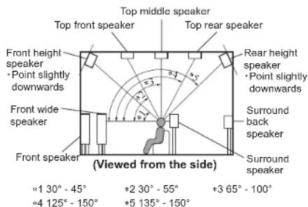
Figure 18- Speaker angles
Before proceeding with Audyssey® Auto Setup, it is very important to first go into the Setup Mode to establish the correct settings for your specific Loudspeaker complement and location in the Home Theater Room. This will not only assure the best acoustic performance using Audyssey® Room Equalization Correction, but it will also assure the best sonic performance using the latest in surround sound technology built into the MX123.
The acoustic characteristics of the connected speakers and listening room are measured and the optimum settings are made automatically.
Audyssey® Setup
Assemble the supplied setup microphone and stand, then place it in the Main Listening Position or Focus Position. See Figure 17 on page 28.
For best results:
- Make the room as quiet as possible. Background noise can disrupt the room measurements. Close windows and turn off the power on electronic devices (radios, air conditioners, fluorescent lights, etc.). The measurements could be affected by the sounds emitted by such devices
- During the measurement process, place cell phones outside the listening room. Cell phone signals could disrupt the measurements
- Do not stand between the speakers and Sound calibration microphone or allow obstacles in the path while the measurements are being made. Also, install the Sound calibration microphone at least 20 inches (50cm) away from the wall. Failure to do so will result in inaccurate readings
- During the measurement process, audible test tones will come from the speakers and subwoofer(s), but this is part of normal
operation. If there is background noise in the room, these test signals will increase in volume
- Operating VOLUME on the Remote Control unit or VOLUME on the main unit during the measurements will cancel the measurements With the MX123 connected to a TV/Monitor, the supplied microphone connected to the SETUP MIC Jack on the Rear Panel and placed in the "Main Listening Location", perform the following steps along with the instructions appearing On-Screen:
- Press the AVP Push-button, then press the SETUP Push-button.
- Using the Remote Control Directional Push-buttons first select "Speakers" followed by "Audyssey Setup". See Figure 19 below.

Figure 19- Audyssey® Setup Start
- Select "Start", then press Enter.
- Follow the instructions on the screen display and press "Next" to proceed further.
- When the following screen is displayed, select "Begin Test" and press Enter. The first position measurement will start. See Figure 21.
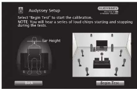
Figure 20— Audyssey® Begin Test
- A test tone will be sent to all channels, one at a time to identify the channels making up your system.
Notes:
- Depending on the number of channels in your system, the illustrations in this Owner's Manual might differ from the actual On-Screen Graphics.
- During the setup process On-Screen error messages may appear, if they do, refer to page 31 for assistance.
- When the detected speakers are displayed, select "Next" and then press Enter. This will start the Measurement Process. A special audio test signal will be sent to all previously detected channels, one at a time. See Figure 21.
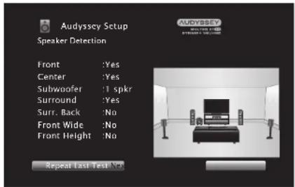
Figure 21 Speaker Detection
Audyssey® Setup will take measurements from eight different locations in the room to achieve the best possible sonic results. The additional measurement locations are indicated on your monitor by numbered blue balloons in the room illustration, placed around the sitting area and the Main sitting position. The Main sitting location is indicated by number "1".
- Following the On-Screen instructions, place the microphone in the 2nd listening position and then press the ENTER Push-Button on the Remote Control to select highlighted on-screen button "Continue". See Figure 22.

Figure 22- Microphone positioning
- Continue following the On-Screen instructions and repeat the measurement process until all eight listening positions have been measured. The On-Screen message will now indicate the measurements are finished. See Figure 23 on page 30.


Figure 23—Measurements complete
Note: Measurement of 3 listening positions are required to enable MultEQ ^® XT32.
- Select "Continue", then press Enter.
- Perform the settings for Audyssey Dynamic EQ® and Audyssey Dynamic Volume®.
The following screen is displayed during the analysis. See Figure 24.

Figure 24 Dynamic EQ
Configure the settings as preferred.
- Dynamic EQ corrects the frequency response in consideration of the audio characteristics of the room and human hearing ability so that sound can
be heard even at low volume.
This is recommended when using the unit with the volume turned down, e.g. when enjoying a movie or TV program in the middle of the night.
- Dynamic Volume adjusts the Output volume to the optimal level while constantly monitoring the level of the audio Input to the unit. Optimal volume control is performed automatically without any loss in the dynamism and clarity of the sound when, for example, the volume suddenly increases for commercials shown during television programs.
- When the analysis and storage ends, unplug the Sound Calibration Microphone from the SETUP MIC Jack on the Rear Panel and press Next.
- Select "Details" and press Enter to verify the measurement results.
- Subwoofers may measure a greater reported distance than the actual distance due to added electrical delay common in subwoofers.
Note: Do not change the speaker connections or subwoofer volume after Audyssey® Setup. If these are changed, run Audyssey® Setup again in order to configure the optimum equalizer settings.
Error Messages
An error message is displayed if Audyssey® Setup could not be completed due to speaker placement, the measurement environment, etc. If an error message is displayed, check the relevant items and perform the necessary measures. Be sure to turn off the power before checking speaker connections.
Subwoofer level error message and how to adjust
The optimal level of each subwoofer channel for Audyssey ^® Setup measurement is 75dB.
During subwoofer level measurement, an error message is displayed when one level of subwoofer
is outside the 72-78dB range. See Figure 25.
Error message
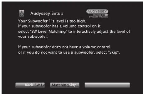
Figure 25 Audyssey® error message
When using a subwoofer with a built-in amplifier (active type), adjust the subwoofer volume so the subwoofer level is within the 72-78dB range.
Retrieving Audyssey® Setup settings
If you set "Restore..." to "Restore", you can return to Audyssey® Setup measurement result (value calculated at the start by MultEQ® XT32) even when you have changed each setting manually. See
Figure 26.

Figure 26 Audyssey ^4 restore
An error message is displayed if Audyssey ^® Setup could not be completed due to speaker placement, the measurement environment, etc. If an error message is displayed, check the relevant items and perform the necessary measures. See Figure 27.
Be sure to turn off the power before checking speaker connections.
| Examples Error Details Corrective Measures | ||
| No Speakers found Sound calibration | tion microphone is not detectedNot all speakers could be detected | Connect the included Sound Calibration Microphone to the SETUP MIC jack on the Rear PanelCheck the speaker connections |
| Ambient noise is too high or level is too low | There is too much noise in the roomSpeaker or subwoofer sound is too low | Either turn off any device generating noise or move it awayPerform again when the surroundings are quieterCheck the speaker installation and the direction in which the speakers are facingAdjust the subwoofer's volume |
| Front R: None The displayed speaker could not be detected | Check the connections of the displayed speaker | |
| Front R: Phase | The displayed speaker is connected with the polarities reversed | Check the polarity of the displayed speakerFor some speakers, this error message may be displayed even if the speaker is properly connected. If you are sure the connection is correct, press ▶ to select “Ignore”, then press ENTER |
Figure 27— Error table
Factory Reset
Use the Factory Reset options to restore the MX123 back to its original factory defaults. These options will erase all changes made to the settings. The firmware will remain the latest installed version.
There are two portions to the Factory Reset. The first is the MCU (microcontroller unit) settings which includes all changes from the default settings. The second includes Network functions such as credentials for Online services. Each part can be reset individually or you can choose to reset both.
To perform a Factory Reset:
- Simultaneously, press and hold two buttons [A] and [B] while powering on the MX123 with the STANDBY/ON button
- Hold all three Buttons for at least 3 seconds while the power is on
- Release the buttons
Choose the two buttons, [A] and [B], according to what you want reset:
| Button A Button B Function | |
| MOVIE MUSIC Reset MCU only | |
| RETURN SLEEP Reset MCU and Network module | |
| RETURN ENTER Reset Network module only |

Bluetooth
The MX123 can pair with many Bluetooth devices. A maximum of 8 Bluetooth device pairings will be remembered. A ninth pairing will replace the oldest registered device. For Bluetooth Remote Control of the MX123 to function, the device must support the AVRCP profile. Supported functions are play, pause, stop, next, and previous. The connected device's volume will control the level of the signal sent to the MX123.
To pair a Bluetooth device with the MX123:
- Activate the Bluetooth setting on your mobile device
- Press and hold the Bluetooth button on the MX123 Remote Control for at least 3 seconds
- Select the MX123 from the list of discovered devices on your mobile Bluetooth device
The Option Button
The Remote Control's OPTION button can be used in the MAIN Zone to adjust settings for the selected Input. Adjustments include:
- Dialog Enhancer- this function adjusts the center channel frequency band to enhance the dialog in the movies and vocals in music for easier listening
- Channel Level Adjust - each channel can be adjusted -12dB to +12dB while listening to music
- Tone-tone can be adjusted and stored for each channel. Tone can not be set if Sound Mode is set to Direct or Pure Direct or when Dynamic EQ is set to On
• Picture Mode- sets Picture Mode for
supported Inputs. For options see "Picture Adjust" on page 20
- All Zone Stereo- allows you to play music from the MAIN ZONE into ZONE2 and ZONE3. This will work for all Input modes except 7.1CH IN
The Headphone Question
The All Zone Stereo option allows you to send analog stereo sound from a compatible HDMI signal to a unit such as a headphone amplifier connected to Zone2 or Zone3. This will allow you to listen via headphones given that you have headphones and an amplifier. You can mute the MAIN ZONE and continue to listen to stereo signals from units connected to the other Zones.
Online Music
Choosing the Online Music Input provides three Input options for playing content:
- TuneIn Internet Radio
- Music Servers
- USB Music
Tuneln Internet Radio provides access to both local and international stations. Stations can be searched by music genre, location, station format or many other search criteria. There are over 120,000 stations (including McIntosh Music) so there is plenty of content that can be freely enjoyed.
Here are playable broadcast station specifications:
| Sampling frequency Bit rate | ||
| WMA (.wma) | 32/44.1/48 kHz | 48-192 kbps |
| MP3 (.mp3) | 32/44.1/48 kHz | 32-320 kbps |
| Sampling frequency Bit rate | ||
| MPEG-4 AAC (.aac/.m4a/.mp4) | 32/44.1/48 kHz | 16-320 kbps |
Music Servers gives you access to files stored on a DLNA compatible server on a PC or NAS connected to your network. Select the server you wish to access from the list under Music Servers. You can browse and search the files. The following formats can be played:
• WMA
• MP3
• WAV
- MPEG-4 AAC
- FLAC
- Apple Lossless
• DSD
Music can also be accessed from a USB memory device inserted into the USB port (labeled USB) in the rear of the MX123. The USB memory device must be formatted as either FAT16 or FAT32. The same file formats listed above for Music Servers are supported.
Spotify Connect
Use your phone, tablet or computer as a remote control for Spotify. Go to spotify.com/connect to learn how.
Compatible Audio Formats
From USB Memory Devices, PC and NAS
The MX123 can play 2-channel audio that is not copyright protected in the following audio formats:
| Format Sampling frequency Bit rate | ||
| WMA(.wma) | 32/44.1/48 kHz 48-192 kbps | |
| MP3(.mp3) | 32/44.1/48 kHz 32-320 kbps | |
| WAV(.wav) | 32/44.1/48/88.2/96/176.4/192 kHz | NA |
| MPEG-4AAC(.aac/.m4a/.mp4) | 32/44.1/48 kHz 16-320 kbps | |
| FLAC(.flac) | 32/44.1/48/88.2/96/176.4/192 kHz | NA |
| AppleLossless(m4a) | 32/44.1/48/88.2/96/176.4/192 kHz | |
| DSD(.dsf/.diff) | 2.8/5.6 MHz NA | |
From HDMI
The MX123 can play the following audio formats via HDMI:
| 2-channel Linear PCM | 2-channel, 32 kHz – 192 kHz, 16/20/24 bit |
| Multi-channel Linear PCM | 7.1-channel, 32 kHz – 192 kHz, 16/20/24 bit |
| Bitstream Dolby Digital / DTS / Dolby Atmos / Dolby TrueHD /Dolby Digital Plus / DTS:X / DTS-HD Master Audio /DTS-HD High Resolution Audio / DTS Express | |
| DSD 2-channel – 5 MHz | 1-channel, 2.8 |
Supported Video Signals
The MX123 supports the HDCP copyright protection system. For proper playback the conencted video device must also support HDCP. Here are supported video signals:
• 480i
• 480p
• 576i
• 576p
- 720p 60/50Hz
• 1080i 60/50Hz
• 1080p 120/100/60/50/24Hz
• 4K 120/100/60/50/30/25/24Hz
• 8K 60/50/30/25/24Hz
USB File and Folder Limits
The MX123 can support up to 5,000 files with a maximum of 500 folders and eight directory levels. Different USB memory devices may have different allowable number of files dependent of capacity and file size.
Memory capacity is 2GB with a FAT16 formatted device and 2TB with FAT32 formatting.
About ARC and CEC
Note that the default setting for ARC (Audio Return Channel) is Off. To use ARC, it must be set to On. Turning HDMI Control On will also enable ARC. HDMI Control enables CEC (Consumer Electronics Control) commands to be transmitted over the HDMI cable so your television and MX123 can better communicate. ARC and HDMI Control (CEC) is factory defaulted to Off because the world of ARC and CEC is not yet perfect. It is certainly getting
better, but not every component in the world is speaking precisely the same language. These features can be enabled or disabled at any time on the MX123. See HDMI Setup on page 21. Remember to enable CEC on your television if you want to use CEC with the MX123.
HDMI Control (CEC) should also be set to Off, if you are using a third-party control system so that CEC does compete with your external controller.
The ARC feature, when enabled, will work with the TV Audio input and a television connected to the HDMI Monitor 1 (ARC/eARC) Output. eARC allows for even higher bandwidth and will allow for higher quality audio including uncompressed 7.1 surround, Dolby Atmos and DTS:X.

Packing the MX123
When shipping the MX123, it is highly recommended that the unit be packed as it was originally shipped to avoid damage. Failure to properly pack the unit will likely result in damage. (The front panel is made of glass!) If you need any of the packing material, you can contact McIntosh Customer Service. Use only packing material that is in good condition and replace any material that has seen better days.
It is very important that the four plastic feet are attached to the bottom of the equipment. This will ensure the proper equipment location on the bottom pad. Failure to do this will result in shipping damage.
Quantity Part Number Description
1 034256 Shipping carton only
4 033887 End cap
2 034493 Spacer pad
1 033697 Inside carton only
1 033725 Inner carton top pad
1 034576 Bottom pad
2 034446 Foam plug
4 017937 Plastic foot
4 400159 #10-32 x 3/4" screw
4 404080 #10 Flat washer
1 034499 Accessory Box
2 034500 Slotted foam
1 034501 Divider foam

Figure 28- Re-packing diagram
Audio Specifications
Unless otherwise noted, the below MX123
Specifications where taken with Audyssey ^® bypassed.
Frequency Response
±0.5dB from 20Hz-20,000Hz
Subwoofer:
±0.5dB from 20Hz-8,000Hz
Total Harmonic Distortion
0.005% maximum from 20Hz to 20,000Hz at rated Output
Signal To Noise Ratio
Phono: 86dB below 10mV Input (A Weighted)
High Level: 96dB below rated Output (A Weighted)
Rated Output Voltage
2.5V Unbalanced Outputs (Main)
5.0V Balanced Outputs (Main)
Maximum Voltage Output
6V Unbalanced
12V Balanced
Output Impedance
220 Ohms
Input Impedance
High Level: 20k Ohms Unbalanced and Balanced
Sensitivity for Rated Output
Phono: 4.5mV
High Level: 450mV Unbalanced
900mV Balanced
Maximum Input Signal
Phono: 50mV
High Level: 4.5V Unbalanced and Balanced
Video Specifications
Signal System
NTSC/PAL
HDMI (Inputs and Outputs)
7 inputs, Zone 1 has two 8K outputs, Zone 2 has one 4k output, HDR, Dynamic HDR, HDR 10+ , HLG, Dolby Vision, cARC, Dynamic Lip-sync, 4:4:4 Color, REC. 2020, 3D Video pass-through
HDMI/Coaxial/Optical Digital Input Rate
32kHz to 192kHz, 24-Bit, Dolby Digital, DTS, PCM
Video Resolution
8K/60Hz
4k/120Hz
Fixed Rate Link (FRL)
40 Gbps
18 Gbps TMDS
HDCP
Version 2.3
Gaming
Variable Refresh Rate (VRR)
Quick Media Switching (QMS)
Quick Frame Transport (QFT)
Auto Low Latency Mode (ALLM)
Scaling
Analog and Digital Video Inputs scaled to a 8K Digital Signal
Component Video Output Level
Y Output Level 1.0Vp-p (75 OHM)
PB/CB Output Level 0.7Vp-p (75 OHM)
PR/CR Output Level 0.7Vp-p (75 OHM)
Composite Video Output Level
1Vp-p (75 OHM)
General Specifications
Power Requirements
Field AC Voltage conversion of the MX123 is not possible. The MX123 is factory configured for one of the following AC Voltages:
100 Volts, 50/60Hz at 75 watts
110 Volts, 50/60Hz at 75 watts
120 Volts, 50/60Hz at 75 watts
127 Volts, 50/60Hz at 75 watts
220 Volts, 50/60Hz at 75 watts
230 Volts, 50/60Hz at 75 watts
240 Volts, 50/60Hz at 75 watts
Standby, less than 0.5 watt
Note: Refer to the rear panel of the MX123 for the
correct voltage.
Overall Dimensions
Width is 17-1/2 inches (44.5cm)
Height is 7-5/8 inches (19.4cm) including feet
Depth is 19-1/2 inches (49.53cm) including the Front
Panel, Knobs, Rear Panel Connections and USB
Drive
Weight
31 pounds (14Kg) net, 55 pounds (25Kg) in shipping carton
Shipping Carton Dimensions
Width is 25 inches (63.5cm)
Depth is 28 inches (71.12cm)
Height is 18-3/8 inches (46.67cm)

The continuous improvement of its products is the policy of McIntosh Laboratory Incorporated who reserve the right to improve design without notice.
Printed in the U.S.A.
McIntosh Part No. 24114400
- MX123
- The MX123 Audio/Visual Processor marries a long tradition of uncompromising quality with the latest home theater technologies to bring you an unsurpassed luxury entertainment experience.
- Thank you from all of us at McIntosh
- McIntosh Laboratory, Inc.
- Make a Note
- List of Figures
- Table of Contents
- Safety First
- Important Safety Information is supplied in a separate document "Important Additional Operation Information Guide"
- FCC Information (For US Customers)
- IMPORTANT NOTICE: DO NOT MODIFY THIS PROF
- CAUTION:
- COMPLIANCE INFORMATION:
- IC Information (For Canadian Customers)
- PRODUCT:
- Canadian Customers: CAN ICES-3 (B)/NMB-3 (B) RF Exposure Information
- DECLARATION OF CONFORMITY
- IMPORTANT NOTICE: DO NOT MODIFY THIS PRODUCT
- CAUTION:
- Trademark and License Information
- What is in the box
- Where to put it
- operation:
- Making the Cuts
- Connections on the Back
- The Inputs
- The Outputs
- Making Connections
- Bluetooth/Wi-Fi Antenna
- 10baseT LAN
- HDMI
- USB
- Microphone
- RS232
- Wired IR Inputs
- Digital Inputs
- Analog Audio Inputs
- AC Power
- Balanced Audio Outputs
- Power Control (Trigger) Outputs
- Analog Audio Output
- Data Out
- The Front Panel
- Standby On
- The Input Knob
- The Volume Knob
- The Arrow and Enter Buttons
- Status
- Sound Mode Buttons
- Zone Select
- Zone On/Off
- Dimmer
- Sleep Timer
- Changing GUI Language/Video Format
- LED Channel Status Indicators
- Setup
- \*SETUP MENU Audio
- The Setup Menu
- Browser Security Warning
- Your connection is not private
- Speakers- Setup Menu
- Amp Assign
- Setup Menu>Speakers>Manual Setup>Amp Assign
- Speaker Types and Positions
- Speaker Configuration
- Setup Menu>Speakers>Manual Setup>Speaker Config
- Speaker Distances
- Setup Menu>Speakers>Manual Setup>Distances
- Speaker Levels
- Setup Menu>Speakers>Manual Setup>Levels
- Crossovers
- Setup Menu>Speakers>Manual Setup>Crossovers
- Bass
- Setup Menu>Speakers>Manual Setup>Bass
- Front Speaker
- Setup Menu>Speakers>Manual Setup>Front Speaker
- Channel Playback
- Setup Menu>Speakers>Manual Setup>2ch Playback
- Audio- Setup Menu
- Setup Menu>Audio
- Subwoofer Level Adjust
- Setup Menu>Audio>Subwoofer Level Adjust
- Bass Sync
- Setup Menu>Audio>Bass Sync
- Sound Parameter
- Setup Menu>Audio>Sound Parameter
- DFR
- Setup Menu>Audio>DFR
- Audio Delay
- Setup Menu>Audio>Audio Delay
- Volume Setup
- Setup Menu>Audio>Volume
- Audyssey® Options Menu
- Setup Menu>Audio>Audyssey ®
- Video- Setup Menu
- Setup Menu>Video
- Picture Adjust
- Setup Menu>Video>Picture Adjust
- HDMI Setup
- Setup Menu>Video>HDMI Setup
- Output Settings
- Setup Menu>Video>Output Settings
- HDMI Video Output
- Setup Menu>Video>Output Settings> HDMI Video Output
- Video Mode
- Setup Menu>Video>Output Settings>Video Mode
- Video Conversion
- Setup Menu>Video>Output Settings>Video Conversion
- Analog Video Out
- Setup Menu>Video>Video Out
- On Screen Display
- Setup Menu>Video>On Screen Display
- 4K/8K Signal Format
- Setup Menu>Video>4K Signal Format
- TV Format
- Setup Menu>Video>TV Format
- Inputs Setup Menu
- Setup Menu>Inputs
- Input Assign
- Setup Menu>Inputs>Input Assign
- Source Rename
- Setup Menu>Inputs>Source Rename
- Hide Sources
- Setup Menu>Inputs>Hide Sources
- Source Level
- Setup Menu>Inputs>Source Level
- Input Select
- Setup Menu>Inputs Animation Select
- Network
- Setup Menu>Network
- General Setup
- Setup Menu>General
- Save & Load
- Setup Menu>General>Save & Load
- Firmware
- Description of Remote Control Buttons
- Setup Menu>General>Firmware
- NEVER TURN OFF THE MX123 WHILE UPDATES ARE BEING INSTALLED.
- Remote Control Batteries
- Audyssey®
- Audyssey® Setup
- For best results:
- Error Messages
- Subwoofer level error message and how to adjust
- Retrieving Audyssey® Setup settings
- Factory Reset
- To perform a Factory Reset:
- Bluetooth
- The Option Button
- The Headphone Question
- Online Music
- Spotify Connect
- Compatible Audio Formats
- From HDMI
- Supported Video Signals
- USB File and Folder Limits
- About ARC and CEC
- Packing the MX123
- Audio Specifications
- Video Specifications
- General Specifications
Brand : MCINTOSH
Model : MX123
Category : Controller