
P705ESBE - Hob SMEG - Free user manual and instructions
Find the device manual for free P705ESBE SMEG in PDF.

| Product type | Built-in gas hob |
| Brand | SMEG |
| Model | P705ESBE |
| Number of burners | 5 (auxiliary, semi-rapid, medium rapid, large rapid, UR) |
| Surface material | Stainless steel with EVERSHINE treatment |
| Dimensions (W x D x H) | 70 x 50 x 5 cm (estimated) |
| Weight | Approximately 10 kg |
| Power supply | 230 V ~ 50 Hz for electronic igniter |
| Gas supply | Natural gas G20 20 mbar (convertible to LPG G30/G31 28/37 mbar) |
| Burner power | Auxiliary 1.0 kW, Semi-rapid 1.6 kW, Medium rapid 2.3 kW, Large rapid 3.0 kW, UR 3.6 kW |
| Ignition | Integrated electronic ignition with safety device |
| Safety | Thermocouple safety device that cuts off gas if flame goes out |
| Main functions | Cooking and reheating food |
| Maintenance and cleaning | Clean after each use with non-abrasive products; grids and caps washable in hot water |
| Spare parts and repairability | Spare injectors supplied for different gases; SMEG after-sales service |
| Warranty | 2 years standard |
| General information | Household use only; installation by qualified professional |
Frequently Asked Questions - P705ESBE SMEG
User questions about P705ESBE SMEG
0 question about this device. Answer the ones you know or ask your own.
Ask a new question about this device
Download the instructions for your Hob in PDF format for free! Find your manual P705ESBE - SMEG and take your electronic device back in hand. On this page are published all the documents necessary for the use of your device. P705ESBE by SMEG.
USER MANUAL P705ESBE SMEG
- Instructions for safe and proper use 19
- Positioning of hob 20
2.1 Attachment to support structure 20
3. Electrical connection 22
4. Gas connection 23
4.1 Connection to LPG 24
4.2 Ventilation of rooms 24
4.3 Discharge of combustion products 24
- Adapting to different types of gas 25
5.1 Removing the hob 25
5.2 Regulation for LPG 26
5.3 Regulation for natural gas 26
5.4 Regulation of primary air 27
5.5 Reassembling the hob 27
5.6 Regulation of minimum for natural gas 27
5.7 Regulation of minimum for LPG 28
5.8 Arrangement of burners on hob 28
5.9 Lubrication of gas taps 28
6.Description of controls 29
6.1 Front control panel 29
- Using the hob 30
7.1Burner lighting with safety device 30
7.2 Practical advice for using the burners 30
7.3 Diameter of containers 30
- Cleaning and maintenance 31
8.1 Cleaning stainless steel 31
8.2 Cleaning of components 31
THESE INSTRUCTIONS ARE VALID ONLY FOR END USER COUNTRIES WHOSE IDENTIFICATION SYMBOLS APPEAR ON THE COVER OF THIS MANUAL.
THIS BUILT-IN HOB IS CLASS 3.

INSTRUCTIONS FOR THE INSTALLER: these are for the qualified technician who must carry out a suitable check of the gas system, install the appliance, set it functioning and carry out an inspection test.
INSTRUCTIONS FOR THE USER: these contain user advice, description of the commands and the correct procedures for cleaning and maintenance of the appliance.
Further information about the products can be found at www.smeg.com.
1. Instructions for safe and proper use
THIS MANUAL IS AN INTEGRAL PART OF THE APPLIANCE AND THEREFORE MUST BE KEPT IN ITS ENTIRETY AND IN AN ACCESSIBLE PLACE FOR THE WHOLE WORKING LIFE OF THE COOKING HOB. WE ADVISE READING THIS MANUAL AND ALL THE INSTRUCTIONS THEREIN BEFORE USING THE COOKING HOB. ALSO KEEP THE SERIES OF NOZZLES SUPPLIED. INSTALLATION MUST BE CARRIED OUT BY QUALIFIED PERSONNEL IN ACCORDANCE WITH THE REGULATIONS IN FORCE. THIS APPLIANCE IS INTENDED FOR DOMESTIC USES AND CONFORMS TO CURRENT REGULATIONS IN FORCE. THE APPLIANCE HAS BEEN BUILT TO CARRY OUT THE FOLLOWING FUNCTIONS: COOKING AND HEATING-UP OF FOOD. ALL OTHER USES ARE CONSIDERED IMPROPER.
THE MANUFACTURER DECLINES ALL RESPONSIBILITY FOR IMPROPER USE.
DO NOT LEAVE THE PACKING IN THE HOME ENVIRONMENT. SEPARATE THE VARIOUS WASTE MATERIALS AND TAKE THEM TO THE NEAREST SPECIAL GARBAGE COLLECTION CENTRE.
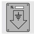
IT IS OBLIGATORY FOR THE ELECTRICAL SYSTEM TO BE GROUNDED ACCORDING TO THE METHODS REQUIRED BY SAFETY RULES.
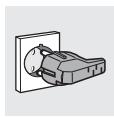
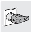
THE PLUG TO BE CONNECTED TO THE POWER CABLE AND THE SOCKET MUST BE THE SAME TYPE AND MUST CONFORM TO CURRENT REGULATIONS.
THE SOCKET MUST BE ACCESSIBLE AFTER THE APPLIANCE HAS BEEN BUILT IN.
NEVER UNPLUG BY PULLING ON THE CABLE.
IMMEDIATELY AFTER INSTALLATION CARRY OUT A BRIEF INSPECTION TEST OF THE COOKING HOB, FOLLOWING THE INSTRUCTIONS BELOW. SHOULD THE APPLIANCE NOT FUNCTION, DISCONNECT IT FROM THE SUPPLY AND CALL THE NEAREST TECHNICAL ASSISTANCE CENTRE. NEVER ATTEMPT TO REPAIR THE APPLIANCE.
ALWAYS CHECK THAT THE CONTROL KNOBS ARE IN THE "ZERO" (OFF) POSITION WHEN YOU FINISH USING THE HOB.
DO NOT PUT PANS WITHOUT PERFECTLY SMOOTH AND FLAT BOTTOMS ON THE COOKING HOB GRIDS.
DO NOT USE RECIPIENTS OR GRIDDLE PLATES THAT EXTEND BEYOND THE EXTERNAL PERIMETER OF THE HOB.
THE I.D. PLATE WITH TECHNICAL DATA, REGISTRATION NUMBER AND BRAND NAME IS POSITIONED VISIBLY UNDER THE CASING, ATTACHED TO THIS MANUAL AND APPLIED TO THE QUALITY CERTIFICATE.
THE PLATE ON THE CASING MUST NOT BE REMOVED.
THE HOB IS TO BE USED BY ADULTS ONLY. DO NOT LET UNSUPERVISED CHILDREN PLAY WITH THE HOB.
THIS APPLIANCE IS MARKED ACCORDING TO THE EUROPEAN DIRECTIVE 2002/96/EC ON WASTE ELECTRICAL AND ELECTRONIC EQUIPMENT (WEEE).
THIS GUIDELINE IS THE FRAME OF A EUROPEAN-WIDE VALIDITY OF RETURN AND RECYCLING ON WASTE ELECTRICAL AND ELECTRONIC EQUIPMENT.

The manufacturer declines all responsibility for damage to persons or things caused by non-observation of the above prescriptions or by interference with any part of the appliance or by the use of non-original spares.
2. Positioning of hob
The following operation requires building and/or carpentry work so must be carried out by a competent tradesman.
Installation can be carried out on various materials such as masonry, metal, solid wood or plastic laminated wood as long as they are heat resistant (T 90^ ).
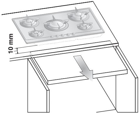
2.1 Attachment to support structure
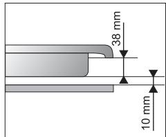
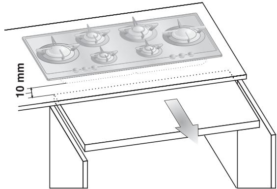
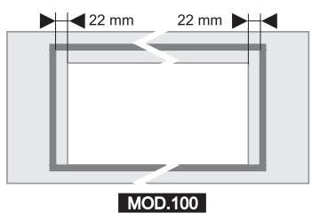
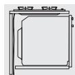
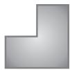
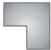
Create an opening with the dimensions shown in the figure in the top surface of the counter, keeping a minimum distance of 50~mm from the rear border. This unit may be set against walls that are higher than the hob as long as distance "X" (see figure) is maintained to prevent damage to the walls due to overheating. Make sure there is a minimum of 750~mm between the hot plate flames and any shelf that may be installed directly above them. In case of installation on a hollow compartment with doors, a separating panel has to be placed under the hob. Keep a minimum distance of 10~mm between the bottom of the unit and the panel surface. The panel has to be easily removable to allow access in the event of technical service.
MOD.70
Whenever a cooker hood is to be installed above the hob, refer to the instruction manual to ensure it is installed at the correct distance.
MOD.60
X=220mm
X=280mm
100 = x - 8
12 =
MOD:100
X = 280mm
MOD.100
一
50 > x < 100
3^x = - 2 + 22
Instructions for the installer
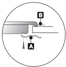
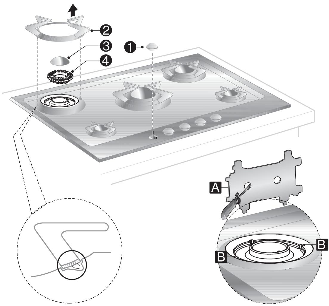
Carefully position the insulation gasket (supplied) on the external perimeter of the hole made in the top surface (see figures below) and try to make it stick to the entire surface by applying light pressure with your hands. Refer to the distances shown in the figure for the model to be installed, keeping in mind that for both models the long front side has to skim the hole. Secure the hob to the counter with brackets A (supplied). Carefully trim any excess from border B of the gasket. The distances in the following drawing refer to the hole on the inner side of the gasket.
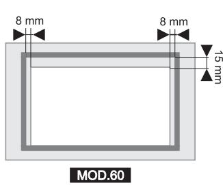
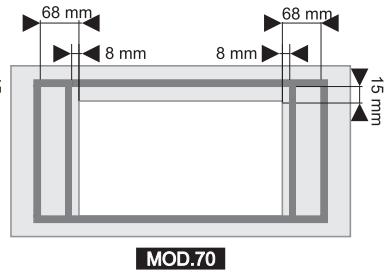
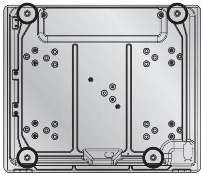
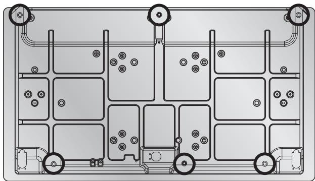
The diagram below shows the exact positions of the holes to be used for clamping the hob to the top correctly.
3. Electrical connection
Make sure that the voltage and capacity of the power line conform to the data shown on the plate located under the casing. Do not remove this plate for any reason.
The plug on the end of the supply cable and the wall socket must be the same type and conform to the current electrical system regulations. Check that the power line is adequately grounded.
Pass the power supply cable through the back of the unit, taking care that it does not touch the bottom casing of the hob or the oven (if any) installed underneath it.
On the power line, install an omnipolar cut-off device with contact cut-off distance greater than or equal to 3 mm, located in an easily accessible position near the unit.
Do not use reducers, adapters or shunts.
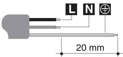
If the power cable is replaced, the wire section on the new cable must not be less than 0.75 mm^2 (3 x 0.75 cable), keeping in mind that the end to be connected to the hob must have the ground wire (yellow-green) longer by at least 20 mm . Use only H05V2V2-F cable or similar which has a maximum temperature of 90^ . Any replacement needed should be carried out by a specialised technician who should make the mains connections according to the following diagram.
L = brown
N = blue
12 = yellow-green

The power lead must be changed by the manufacturer or by an authorised service centre to prevent any risks.

The manufacturer will not be liable for any damage to persons or property caused by non-observation of the above instructions or deriving from the tampering of even a single part of the hob.
4. Gas connection
If the appliance is installed on an oven, the gas pipe must not be passed along the back of the oven, as this may cause overheating.
Connection to the gas mains may be made with a rigid copper pipe or with a flexible pipe and conforming to the provisions defined by standard regulations in force.
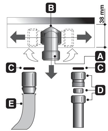
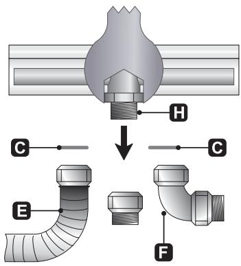
On some models, for easier connection the union A on the back of the appliance can be adjusted sideways. For this purpose, loosen hexagon nut B, turn fitting A to the desired position, and retighten hexagon nut B (tightness is ensured by a biconical brass ring). Use a soapy solution to check for proper tightness. Never use a free flame. On some model the connection to the pipe must be made using a 90^ union. The union H cannot be turned.
The hob has been inspected for G20 (2H) natural gas at a pressure of 20 mbar. For use with other types of gases, see Section "5. Adapting to different types of gas". The gas intake fitting is 12 " gas external threaded (ISO 228-1).
Connection with rigid copper pipe: the connection to the gas mains must not provoke stress of any kind on the hob. Connection may be made by using biconical adapter D with insertion of gasket C (supplied).
Connection with copper pipe and 90^ union (only on some models): the connection to the gas mains must not provoke stress of any kind on the hob. The connection must be made using a 90^ F union, fitting the seal C provided in all cases. Screw the union F onto the gas train H of the hob using 2 spanners in opposite directions.
Connection with flexible pipe (All models): use only flexible pipes conforming to standard regulations in force, inserting gasket C (supplied) between fitting A and flexible pipe E.
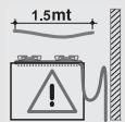
The flexible pipe has to be installed so that pipe length does not exceed 1.5 meters of maximum extension. Make sure that the pipes do not touch any moving parts or become damaged.
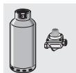
4.1 Connection to LPG
Use a pressure regulator and make the connection to the tank according to the provisions of standards regulations in force. Make sure that feed pressure conforms to the levels shown in the table in Section "5.2 Regulation for LPG".
4.2 Ventilation of rooms
The hob may be installed only in rooms with permanent ventilation, as required by standards regulations in force. The room in which the hob is installed must have sufficient air flow to satisfy the requirements of normal gas combustion and of necessary air exchange in the room. The air intakes, protected by screens, must be appropriately sized (regulations in force) and placed so as not to be blocked in any way.
The room where the oven is installed should be suitably ventilated to avoid overheating or excess humidity produced by cooking, and in the case of lengthy use a window should be opened or the speed of any ventilators should be increased.
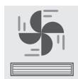
4.3 Discharge of combustion products
Discharge of combustion products must be guaranteed by means of hoods connected to a natural draught flue with certain efficiency, or by means of forced aspiration.
An efficient aspiration system requires careful planning by a specialist capable of installing it, respecting the positions and distances prescribed by standards. After installation, the installer must issue a certificate of conformity.
5. Adapting to different types of gas

Before performing any cleaning or maintenance work, detach the hob from the electrical socket.
The hob has been inspected for G20 (2H) natural gas at a pressure of 20 mbar.
For functioning with other types of gas the nozzles must be replaced and the primary air adjusted.
To replace the nozzles and regulate the burners, you have to remove the top as described in the following paragraph.
5.1 Removing the hob
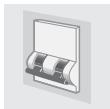
Remove all of the burner components by following the numerical sequence shown in the figure:
- remove all of the knobs (1) by pulling them upward;
- remove the grids (2), lifting up one of the two horizontal spokes;
- remove the burner caps (3) and flame caps (4);
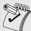
- with wrench A (supplied), open the bayonet clamps on the burner rings by levering on guides B;
- after having removed all of the above-described components, raise the surface to access the burners and gas taps.
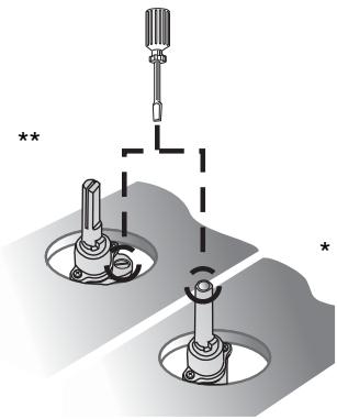
5.2 Regulation for LPG
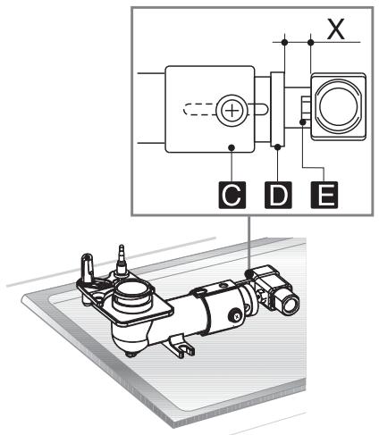
Loosen screw C and push air regulator D to the bottom.
With a 7 mm wrench, remove nozzle E and replace it with the proper one (follow the instructions on the reference tables for the type of gas to be used). The torque wrench setting of the nozzle must not exceed 3 Nm.
Regulate the air by sliding regulator D until reaching distance "X" shown in the table in paragraph "5.4 Regulation of primary air".
Lock regulator D by tightening screw C.
| Burner | Rated heating capacity (kW) | LPG – G30/G31 28/37 mbar | ||||||
| Nozzle diameter 1/100 mm | By-pass mm 1/100 | Reduced flowrate (W) | Flowrate g/h G30 | Flowrate g/h G31 | ||||
| Auxiliary | 1.0 | 48 | 30(**) | 30 (*) | 450 | 73 | 72 | |
| Semi rapid | 1.6 | 62 | 30(**) | 33 (*) | 500 | 116 | 114 | |
| Medium rapid | 2.3 | 75 | 40(**) | 40 (*) | 700 | 167 | 164 | |
| Large rapid | 3.0 | 82 | 40(**) | 45 (*) | 800 | 218 | 215 | |
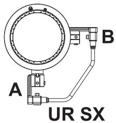
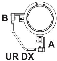
| UR | A | 3.6 | 76 | 48(**) | 50 (*) | 1000 | 261 | 257 |
| B | 48 | |||||||
^/^* diameters marked * and ** must be fitted respectively on valves marked * and ** shown inpoint "5.6 Regulation of minimum for natural gas".
CAUTION: for references A and B on the In UR and rh UR burners, see drawings at side.
5.3 Regulation for natural gas
The hob has been inspected for G20 (2H) natural gas at a pressure of 20 mbar. To allow the unit to work with this type of gas, perform the same operations described in paragraph "5.2 Regulation for LPG", but choose the nozzles and regulate the primary air for natural gas, as shown in the following table and in paragraph "5.4 Regulation of primary air".
| Burner | Rated heating capacity (kW) | Natural gas - G20 20 mbar | ||
| Nozzle diameter 1/100 mm | Reduced flowrate (W) | |||
| Auxiliary | 1.0 | 73 | 400 | |
| Semi rapid | 1.65 | 92 | 500 | |
| Medium rapid | 2.3 | 110 | 700 | |
| Large rapid | 3.0 | 126 | 800 | |
| UR | A | 3.6 | 115 | 1000 |
| B | 73 | |||
5.4 Regulation of primary air
Referred to distance "X" in mm.

| BURNER | G20 20 mbar | G30/G31 28/37 mbar | |
| Auxiliary | 4 | open | |
| Semi rapid | 3 | 2 | |
| Medium rapid | 2 | 2.5 | |
| Large rapid | 2 | 2.5 | |
| UR | A | 2 | 14 |
| B | 2 | 14 | |
To identify the burners on your hob, refer to the drawings in point "5.8 Arrangement of burners on hob
If after air setting the flame appears as shown in the diagram:
A
B
C
the following adjustments must be made:
A: the flame is noisy and unstable and comes away from the burner; the primary air intake is open too far.
B: The flame is cloudy and dull or has yellow dots and wraps round the burner; the primary air intake is closed too far.
C: The flame is blue, clear and stable and neither comes away from or wraps round the burner; the air is set correctly.
5.5 Reassembling the hob
Follow the instructions given in paragraph "5.1 Removing the hob", but in the reverse order.
When replacing the burner rings, remember that they have to be tightened completely by means of the wrench supplied, otherwise the flame interruption zones on the flame caps will not be aligned with the grid spokes.
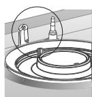
When positioning the grids, make sure that the pins are aligned with their seats in the surface, then press them in with the palm of your hand until they lock in place.
5.6 Regulation of minimum for natural gas
Replace the components on the burner and slide the knobs on the gas tap pins.
Light the burner and set it at minimum position.
Remove the knob and turn the regulation screw inside or next to the gas tap pin (depending on the model) until you get a suitable minimum flame.
Replace the knob and check flame stability by rapidly turning the knob from maximum to minimum. The flame should not go out.
5.7 Regulation of minimum for LPG
To regulate the minimum for LPG, completely tighten (clockwise) the screw inside or next to the gas tap pin (depending on the model).
The diameters of the by-passes for each burner are given in table "5.2 Regulation for LPG".
After regulation for a gas other than that inspected, replace the label on the casing with one for the new gas. The label is inside the bag that contains the nozzles.
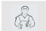
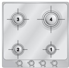
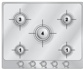
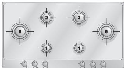
5.8 Arrangement of burners on hob
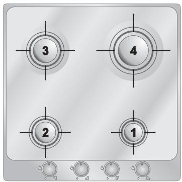
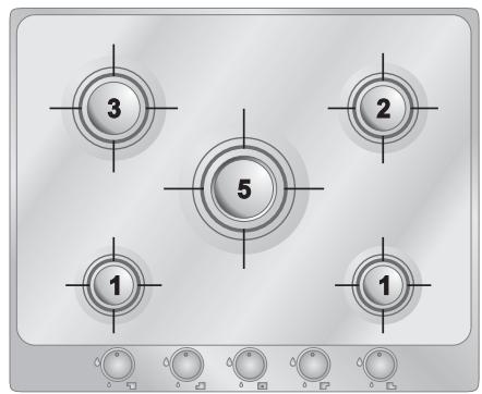
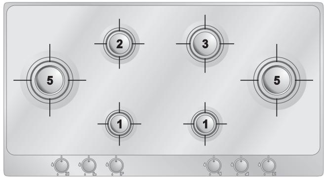
BURNERS
1 Auxiliary
2 Semi rapid
3 Medium rapid
4 Large rapid
5 UR
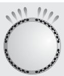
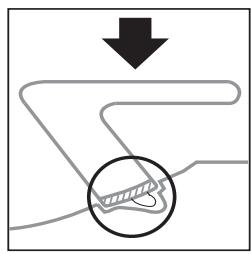
If the flame of the UR burners have unstable flame (the ring does not ignite or has difficulty igniting), clean the perforated ring carefully to remove any residues deposited in the holes. If the problem persists after this cleaning, contact an authorised service centre.
5.9 Lubrication of gas taps

After a while, the gas tap may become hard to turn or lock. If this happens, it has to be cleaned inside and re-greased.
This must be done by a qualified technician.
Instructions for the user
6. Description of controls
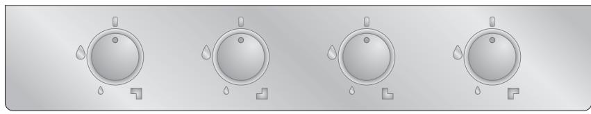
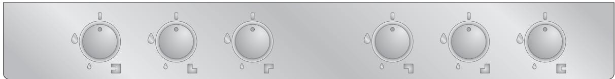
6.1 Front control panel
All of the commands and controls for the hob are found on the front panel.
MODEL 60 CONTROL PANEL
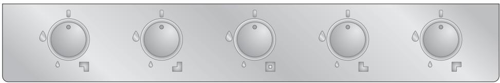
MODEL 70 CONTROL PANEL
MODEL 100 CONTROL PANEL
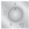
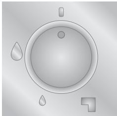
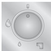
DESCRIPTION OF THE KNOB
The flame is lit by pressing the knob and simultaneously turning it anticlockwise to the minimum flame symbol .
To adjust the flame, turn the knob to the zone between maximum and minimum.
Turn off the flame by turning the knob to position
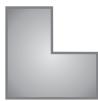
ARRANGEMENT OF BURNERS - Description of symbols
REAR RIGHT
(REAR LEFT ON 100 CM. MOD.)
REAR LEFT
(REAR RIGHT ON 100 CM. MOD.)

FRONT RIGHT
(FRONT LEFT ON 100 CM. MOD.)
FRONT LEFT
(FRONT RIGHT ON 100 CM. MOD.)

MIDDLE LEFT

MIDDLE RIGHT

MIDDLE
7. Using the hob
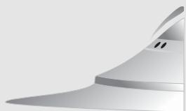
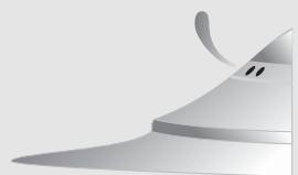
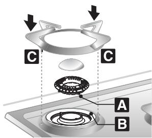
Check that the flame cap crowns, the burner caps and grids are correctly assembled.
Pins A of the flame cap crowns must be inserted in housings B of the burner rings, and pins C on the grids must be blocked in their respective housings on the hob.
7.1 Burner lighting with safety device
Each knob shows the burner it is for (the example at the side corresponds to the front left burner).
The appliance is equipped with an electronic lighter. Just press and simultaneously turn the knob anticlockwise to the minimum flame symbol until the burner lights. Keep the knob pressed down for about 2 seconds to keep the flame alight and activate the safety device. It may happen that the burner goes out when the knob is released. In this case, repeat the operation, keeping the knob pressed down for a longer time.
If the burners should go out accidentally, after a roughly 20 second interval the safety device intervenes to block gas flow, including when the tap is open.
7.2 Practical advice for using the burners
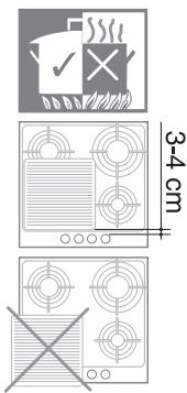
For better burner performance and minimum gas consumption, flat bottomed, even recipients must be used, with covers and proportional in size to the burners (see paragraph "7.3 Diameter of containers").
To avoid overcooking or damage to the surface top while cooking, all recipients or griddles must be positioned within the cooking hob perimeter and must be a minimum distance of 3-4 cm from the knobs.
7.3 Diameter of containers
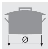

BURNERS
1 Auxiliary 7-18
2 Semi rapid 10-24
3 Medium rapid 18-24
4 Large rapid 20-24
5 UR 20-28
min. and max. (in cm)
8. Cleaning and maintenance

- Do not use steam jets to clean the hob and its components.
- Do not use cleaning products containing chlorine, ammonia or bleach.

Before any intervention, disconnect the power supply of the device.

8.1 Cleaning stainless steel
To keep the hob in good condition, you should clean it after every use (after it has cooled).
8.1.1 Regular daily cleaning of the hob
To clean and preserve the stainless steel surfaces, always use only specific products that do not contain abrasives or chlorine-based acids.
How to use: pour the product on a damp cloth and wipe the surface, rinse thoroughly and dry with a soft cloth or deerskin.
8.1.2 Food stains or residues
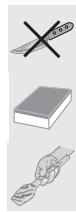
Do not use metallic sponges or sharp scrapers: they will damage the surface.
Use normal, non-abrasive products for steel together with non-scratch sponges and, if necessary, wooden or plastic utensils.
Rinse thoroughly and dry with a soft cloth or deerskin.
8.2 Cleaning of components
8.2.1 Knobs
The knobs are made of stainless steel and therefore should be cleaned in the same way as the hob.
8.2.2 Pan stands and burner caps (EVERSHINE treatment)
The special EVERSHINE treatment makes the polished stainless-steel burners and pan stands highly heat resistant and prevents yellowing due to the exposure to high temperatures. Follow the cleaning instructions below for the best results and to avoid damaging the treatment:
- Remove the burner cap.
- Pull one of the two horizontal spokes of the pan stand upwards to extract it.
- Wash these components with hot water and a non-abrasive cleaner, taking care to remove any deposits. Do not use metal pan scourers, abrasive sponges or sharp scrapers.
- Dry the components.
- Replace the burner caps on their corresponding crowns; position the pan stands, ensuring that the pins C line up with their holes on the hob, then push them down with the palm of your hand until they click into place.
- In case of contact with overly harsh detergents, hard water or spills (cooking water, sauce, coffee etc.), clean the hob as soon as it has cooled.
- Never wash in the dishwasher

8.2.3 Flame cap crowns
The flame cap crowns are removable. Wash them with hot water and non-abrasive detergent. Be careful to remove all deposits.
When you replace them, make sure that they are completely dry and inserted correctly in their housings (see Section "7 Using the hob").
8.2.4 Ignition plugs and safety devices
For good functioning of the lighting ignition plugs and the safety devices, keep them very clean.
Check frequently and clean with a damp cloth when necessary.


- Instructions for safe and proper use
- Positioning of hob
- Attachment to support structure
- Instructions for the installer
- Electrical connection
- Gas connection
- Connection to LPG
- Ventilation of rooms
- Discharge of combustion products
- Adapting to different types of gas
- Removing the hob
- Regulation for LPG
- Regulation for natural gas
- Regulation of primary air
- Reassembling the hob
- Regulation of minimum for natural gas
- Regulation of minimum for LPG
- Arrangement of burners on hob
- BURNERS
- Lubrication of gas taps
- Instructions for the user
- Description of controls
- Front control panel
- DESCRIPTION OF THE KNOB
- ARRANGEMENT OF BURNERS - Description of symbols
- Using the hob
- Burner lighting with safety device
- Practical advice for using the burners
- Diameter of containers
- min. and max. (in cm)
- Cleaning and maintenance
- Cleaning stainless steel
- Regular daily cleaning of the hob
- Food stains or residues
- Cleaning of components
- Knobs
- Pan stands and burner caps (EVERSHINE treatment)
- Flame cap crowns
- Ignition plugs and safety devices
Brand : SMEG
Model : P705ESBE
Category : Hob