TJ550 - Home Automation HAGER - Free user manual and instructions
Find the device manual for free TJ550 HAGER in PDF.


| Product Type | Time Switch |
| Model | TJ550 |
| Brand | Hager |
| Dimensions (H x W x D) | 85 mm x 85 mm x 60 mm |
| Weight | 0.2 kg |
| Power Supply | 230 V AC, 50/60 Hz |
| Switching Capacity | 16 A (resistive load) |
| Number of Channels | 1 |
| Programming Options | Daily and weekly schedules |
| Minimum Switching Interval | 1 minute |
| Display | LCD with backlight |
| Memory Backup | Battery backup (CR2032) |
| Protection Rating | IP20 |
| Operating Temperature | -10°C to +50°C |
| Mounting | DIN rail (35 mm) |
| Maintenance | Clean with dry cloth; avoid liquids |
| Safety | Double insulation, meets EN 60730 |
| Spare Parts | Available from Hager authorized dealers |
| General Information | For indoor use only, not for dimming |
Frequently Asked Questions - TJ550 HAGER
User questions about TJ550 HAGER
0 question about this device. Answer the ones you know or ask your own.
Ask a new question about this device
Download the instructions for your Home Automation in PDF format for free! Find your manual TJ550 - HAGER and take your electronic device back in hand. On this page are published all the documents necessary for the use of your device. TJ550 by HAGER.
USER MANUAL TJ550 HAGER
natural_image
Blank white image with a rounded corner border and faint gray geometric shapes at the bottom (no text or symbols)
natural_image
Close-up of a mechanical component with three numbered parts (1, 2, 3) and no visible text or symbols.

natural_image
Close-up of a gray rectangular button with a white connector, next to a partial view of a device (no visible text or symbols)



natural_image
Completely blank white image with no visible content, text, or symbols.
natural_image
Close-up of a row of 3D keyboard keys in grayscale (no text or symbols visible)
natural_image
Close-up of a white electrical fuse with a black socket and indicator lights (no text or symbols visible)
natural_image
Pure horizontal lines with no text or symbols, no discernible objects or symbols

natural_image
Close-up of a metallic bracket with flanges and a small protrusion (no text or symbols visible)
natural_image
Close-up of a transparent cylindrical object with no visible text or symbols
SUMMARY
Page
- INTRODUCTION .... 3
1.1 PURPOSE OF THE DOCUMENT 3
- GENERAL DESCRIPTION......4
2.3 THE DOMOVEA SOLUTION....5
2.4 FRONT OF THE TJA450 DOMOVEA SERVER 6
- HARDWARE AND SOFTWARE INSTALLATION......8
3.1 HARDWARE INSTALLATION OF THE TJA450 DOMOVEA SERVER ...... 9
3.1.1 Connection diagram....9
3.1.2 Network Installation 9
3.1.3 Update of domovea software version 10
3.2 INSTALLING THE DOMOVEA SOFTWARE PACKAGE (TJ701A) 11
3.2.1 Composition.... 11
3.2.2 Connection diagram.... 11
3.3 INSTALLING THE SOFTWARE....11
3.3.1 32 or 64 bit Windows?....11
3.3.2 Installing the server software (TJ701A only) 12
3.3.3 Installing the client software and configuration tool 12
3.3.4 installation of software on iOS and Android OS devices 12
3.3.5 installation of software on Android touch screens.... 12
- CONFIGURATION TOOL DESCRIPTION 14
4.1 CONNECTING A TERMINAL TO THE DOMOVEA SERVER 14
4.1.1 Connection behind a DHCP server.... 14
4.1.2 Connecting without a DHCP server.... 15
4.2 NAVIGATION INTERFACE 18
4.3 MAIN MENU 19
5.5 CREATING KNX LINKS....32
5.5.1 ETS Project....32
| Date: 2015-09-016T 8200-02h | INSTALLER MANUALSUMMARY | :hager |
5.5.2 Project TXA100....50
5.6 CURVES (SENSORS) 51
5.6.1 Different types of comparison 53
- CONFIGURATION TOOL ADVANCED FUNCTIONS....58
6.1 GROUPS....58
6.2 DEVICES....58
6.3 CAMERAS 60
6.3.1 Creating a link with a camera 62
6.3.2 Dashboard....63
6.3.3 Importing a camera template 64
6.3.4 Doorphone 65
6.4 AUTOMATION....65
6.4.1 Sequences....65
6.4.2 Programs 65
6.4.3 Measurements 65
6.4.4 Profiles....65
6.5 ICONS AND BACKGROUNDS....74
- APPENDIXES....77
7.1 DEVICE LIST AND DETAILS....77
7.1.1 Lighting....77
7.1.2 Switched socket 79
7.1.3 Command....79
7.1.4 Shutter 80
7.1.5 HVAC 83
7.1.6 Ventilation 87
7.1.7 KNX scene....89
7.1.8 Energy Management 89
7.1.9 Sensor....89
7.1.10 Security 91
7.1.11 Others....92
| Date: 2015-09-016T 8200-02h | INSTALLER MANUALINTRODUCTION |  |
1. INTRODUCTION
1.1 PURPOSE OF THE DOCUMENT
The descriptions in this manual are intended to familiarize the installer with the domovea system provided by Hager.
The procedures in this manual are intended to assist the installer during the domovea system installation and configuration through appropriate software tools.
For better understanding, a specific example will be described and illustrated.
2. GENERAL DESCRIPTION
2.1 SYSTEM OVERVIEW
domovea is the control and visualization software for Tebis installations. It provides access to all features for home automation from computer terminals (PC, touch screens) in the house. Under the normal Tebis commands, domovea adds new comfort and safety elements: triggering sequences (planned or immediate action sequences), changing the configuration of the house based on events or periods, viewing via images the proper execution of prior commands, or commands in progress, all with a single click.
2.2 OVERVIEW OF THE SYSTEM
The domovea system consists of three modules:
- Server:
A TJA450, a hardware interface between the KNX bus and the local network of the house OR
A server PC linked to KNX/USB (TJ701A) media coupler able to perform the same function.
- Client:
This software is the client interface. It must be installed on a touch screen, PC or a mobile device. The maximum number of clients that can be installed behind a server is 30.
- Configuration Tool:
This software is used to configure and program the client interface. It can be loaded on the installer's laptop.
The following diagram describes the hardware architecture of a Tebis/domovea installation:

flowchart
graph TD
    A["KNX"] --> B["Device 1"]
    A --> C["Device 2"]
    A --> D["Device 3"]
    A --> E["Device 4"]
    B --> F["Router"]
    C --> F
    D --> F
    E --> F
    F --> G["LAN"]
    G --> H["PC"]
    G --> I["Computer"]
    G --> J["Desktop"]
    F --> K["web"]
    K --> L["www.domovea.com"]
    style F fill:#f9f,stroke:#333
    style G fill:#ccf,stroke:#333
    style K fill:#cfc,stroke:#333
    style L fill:#fcc,stroke:#333
The domovea system is based on two different networks in a building:
- The KNX network (cable, wireless or mixed) in which all KNX sensors, actuators, switches, etc., are installed.
- The Ethernet network where all the IP clients are connected to the LAN (local network): PC, touch screens, cameras and so on.
The TJA450 domovea server provides a gateway between the two networks.
Domovea remote access is carried out via the www.domovea.com portal.
2.3 THE DOMOVEA SOLUTION
| Reference | Description | Composition |
| TJA450 | Local visualisation and automation server | - TJA450: domovea server- USB key containing the software |
| TJ701A | Command software- visu.KNX | - TH201: KNX/USB media coupler- USB cable- USB key containing the software |
| TJ550 | domovea remote access key | - USB Key containing the remote access license for the domovea.com portal |
| TGA200 | 24 VDC power supply | - 230VAC/24VDC 1A power supply |
| TJA451 | domovea system kit | - TJA450: domovea server pre-activated for remote access- TGA200: 24 VDC power supply- USB key containing the software |
| Date: 2015-09-016T 8200-02h | INSTALLER MANUALGENERAL DESCRIPTION |  |
2.4 FRONT OF THE TJA450 DOMOVEA SERVER
The following table summarizes the meaning of each LED (1, 2 and 3):
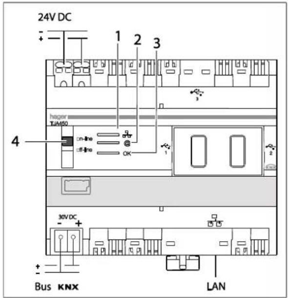
| LED | Status | Meaning | Fault correction |
| 1 | Off | Network cable unplugged | Connect the network cable |
| Solid red | IP address conflict | Check the IP addresses used on the network | |
| Flashing green | Waiting on IP address from the DHCP server | / | |
| Solid green | IP address received | / | |
| @2 | Off | No connection to the portal | / |
| Solid red | Portal is not available or connection refused | Check Internet access | |
| Flashing green | Connection to the portal in progress | / | |
| Solid green | Connection to the portal established | / | |
| OK3 | Flashing red | Power problem | Check the power supply |
| Solid red | Application software fault | Perform a server reset. If the problem persists, contact Hager technical support | |
| Flashing green | domovea server starting up | / | |
| Solid green | domovea server operational | / |
The two switch positions (4) are:
On-line:
- The IP network is connected,
- The domovea portal is connected,
- The KNX bus is connected,
- If the server is configured for a DHCP (factory default) connection, the server expects an IP address from a DHCP server. After 40 seconds, if no IP address is assigned, the server automatically enters the fallback IP address (192.168.0.253).
- If the server is configured with a static IP address, it will immediately take into account the IP address it has been assigned. In this case, it will never revert to the fallback IP address.
Off-line:
- The IP network is connected,
- The domovea portal is disconnected,
- The KNX bus is disconnected,
- Regardless of the server configuration (fixed IP or DHCP) for the connection, the server waits for an IP address from a DHCP server. After 40 seconds, if no IP address is assigned, the server automatically enters the fallback IP address (192.168.0.253).
Recommendations:
In general, the switch (4) must always be set to on-line.
Switch to off-line in the following cases:
- Need to be able to disconnect from the portal and the KNX network
- Loss of the server IP address in fixed IP configuration: in this case, the off-line mode will allow reading or reconfiguring the server's IP address through the domovea configuration software.
The TJA450 domovea server has three USB ports: two in the fronts behind the rubber caps and one on top.
These three USB connectors are used to perform the update of the server's software version.
| Date: 2015-09-016T 8200-02h | INSTALLER MANUALHARDWARE AND SOFTWARE INSTALLATION |  |
3. HARDWARE AND SOFTWARE INSTALLATION
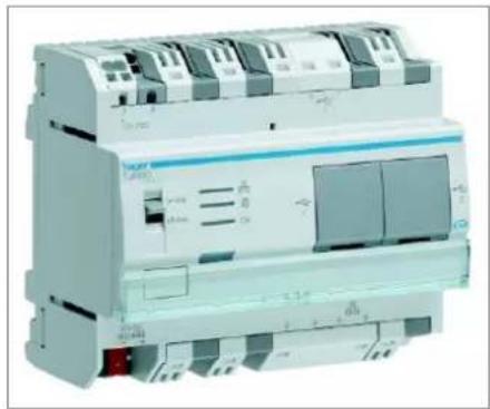
The TJA450 domovea server must be installed in the electrical panel or in the VDI (Voice, Data, Images) panel.
natural_image
Exterior view of a white industrial circuit breaker with multiple fuses and control panel (no visible text or symbols)The TJ701A media coupler must be installed close to the server PC

natural_image
Coiled black cable connected to a beige electronic device (no visible text or symbols)The Server software must be installed on the Server PC with a Microsoft operating systems: Windows XP, Windows Vista, Windows 7, Windows 8, 32 or 64 bits.
The Client software and the Configuration Tools can be installed on a computer terminal equipped with a Microsoft operating system (Windows XP, Windows Vista, Windows 7, Windows 8, 32 or 64 bits).


domovea Client domovea Configuration Tool
3.1 HARDWARE INSTALLATION OF THE TJA450 DOMOVEA SERVER
3.1.1 CONNECTION DIAGRAM
The TJA450 domovea server must be installed in the electrical panel or in the VDI panel.
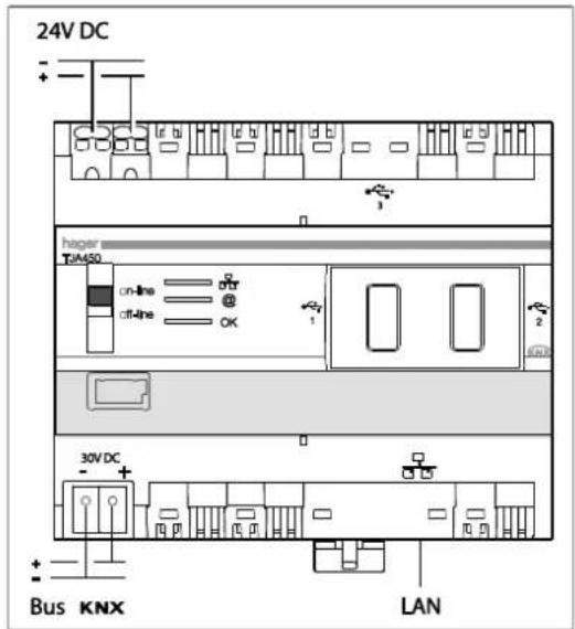
NOTE: If there is no VDI distribution panel, the server can be installed in the electrical distribution panel. In this case, the ELV (Extra Low Voltage) connections and the SELV (Safety Extra Low Voltage) connections must be secured in an appropriate way.
NOTE: The server should not be connected to a PoE (Power over Ethernet) network.
3.1.2 NETWORK INSTALLATION
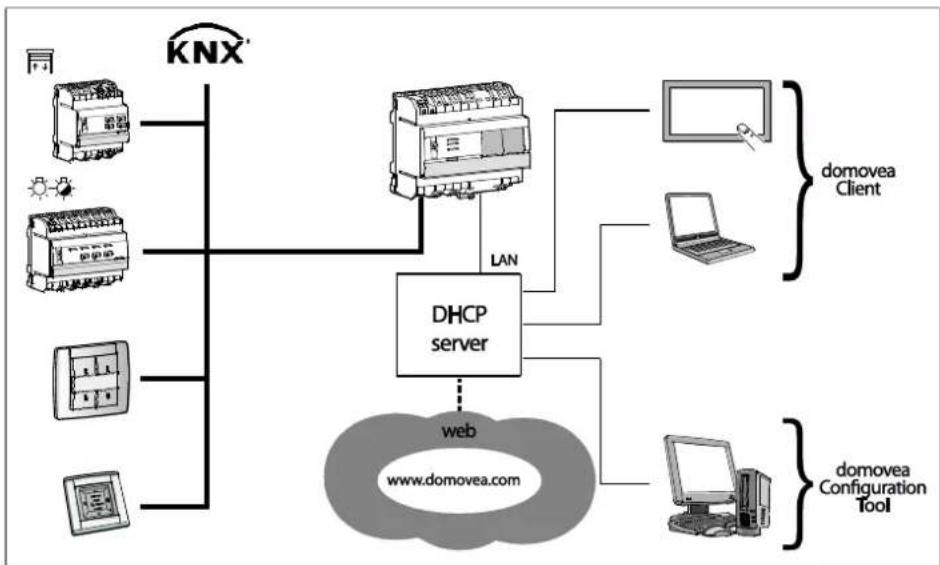
Installation behind a DHCP server
The TJ450 domovea server is connected to a DHCP server (router or other device with DHCP). In this case, the server automatically obtains an IP address from the DHCP server.
flowchart
graph TD
    A["同"] --> B["KNX"]
    C["同"] --> D["LAN"]
    E["同"] --> F["LAN"]
    G["同"] --> H["LAN"]
    I["同"] --> J["LAN"]
    K["同"] --> L["LAN"]
    M["同"] --> N["LAN"]
    O["同"] --> P["LAN"]
    Q["同"] --> R["LAN"]
    S["同"] --> T["LAN"]
    U["网"] --> V["网"]
    W["网"] --> X["网"]
    Y["网"] --> Z["网"]
    AA["网"] --> AB["网"]
    AC["网"] --> AD["网"]
    AE["网"] --> AF["网"]
    AG["网"] --> AH["网"]
    AI["网"] --> AJ["网"]
    AK["网"] --> AL["网"]
    AM["网"] --> AN["网"]
    AO["网"] --> AP["网"]
    AQ["网"] --> AR["网"]
    AS["网"] --> AT["网"]
    AU["网"] --> AV["网"]
    AW["网"] --> AX["网"]
    AY["同"] --> AZ["LAN"]
    BA["同"] --> BB["DHCP server"]
    BC["同"] --> BD["domovea Client"]
    BE["同"] --> BF["domovea Client"]
    BG["同"] --> BH["domovea Client"]
    BI["同"] --> BJ["domovea Client"]
    BK["同"] --> BL["domovea Client"]
    BM["同"] --> BN["domovea Client"]
    BO["同"] --> BP["domovea Client"]
    BQ["同"] --> BR["domovea Client"]
    BS["同"] --> BT["domovea Client"]
    BU["同"] --> BV["domovea Client"]
    BW["同"] --> BX["domovea Client"]
    BY["同"] --> BZ["domovea Client"]
    CA["同"] --> CB["domovea Client"]
    CC["同"] --> CD["domovea Client"]
    CE["同"] --> CF["domovea Client"]
    DG["同"] --> DH["domovea Client"]
    DI["同"] --> DJ["domovea Client"]
    DK["同"] --> DL["domovea Client"]
    DM["同"] --> DE["domovea Client"]
    DF["同"] --> DG
    DG --> DG
NOTE: Connecting to the domovea.com Web portal requires a VPN connection.
| Date: 2015-09-016T 8200-02h | INSTALLER MANUALHARDWARE AND SOFTWARE INSTALLATION |  |
Installing without a DHCP server
It is possible to connect the TJ450 domovea server directly to the installer's PC where the Configuration Tool is installed. In this case, after 40 seconds, the server will adopt the following configuration:
- IP address: 192.168.0.253,
- Subnet Mask: 255.255.255.0.

flowchart
graph TD
    A["KNX"] --> B["LAN"]
    A --> C["domovea Configuration Tool"]
    D["Image 1"] --> E["Computer"]
    F["Image 2"] --> G["Computer"]
    H["Image 3"] --> I["Computer"]
    J["Image 4"] --> K["Computer"]
    L["Sun icon"] --> M["Light Bulb"]
    N["Radio panel"] --> O["Radio System"]
3.1.3 UPDATE OF DOMOVEA SOFTWARE VERSION
The update file is available from the Hager Customer Support Centre or by download from the portal at: www.domovea.com.
To update the domovea server software version:
- Copy the folder named "autorun" containing the update file with the extension .cab to the root folder of a USB device.
- Insert the USB into a USB port on the TJA450 domovea server.
The "OK" LED flashes for about a minute then turns off.
The server then restarts with the new software version.
NOTE: If you also copy the folder named "softwares" to the root folder of this USB device and you leave the USB device connected to the server after the update, domovea customers (apart from iOS and Android) and the domovea web configurator will automatically be updated upon completion.
3.2 INSTALLING THE DOMOVEA SOFTWARE PACKAGE (TJ701A)
3.2.1 COMPOSITION
The TJ701A domovea software package TJ701A consists of:
- A KNX/USB media coupler
- A USB cable
- A USB key containing the software for the domovea installation
3.2.2 CONNECTION DIAGRAM
The TJ701A media coupler must be installed close to the server PC

flowchart
graph LR
    A["KNX"] --> B["TJ701"]
    B --> C["Server PC"]
    D["KNX connector"] --> B
    E["USB connector"] --> B
3.3 INSTALLING THE SOFTWARE
3.3.1 32 OR 64 BIT WINDOWS?
The installation of the Client software and the Configuration Tools can be carried out on a computer terminal equipped with a Microsoft operating system (Windows XP, Windows Vista, Windows 7: 32 or 64 bits).
To determine the 32 or 64 bit Windows version:
- Access the System Properties window by holding down the Windows + Pause keys. The operating system is displayed on the General tab:
- For a 64-bit operating system, the x64 reference appears after the name of the operating system,
- For a 32-bit operating system, no reference appears after the name of the operating system.
3.3.2 INSTALLING THE SERVER SOFTWARE (TJ701A ONLY)
The Server software (with TJ701A only) can be installed on a PC with a Microsoft operating system: Windows XP SP3, Windows Vista, Windows 7, Windows 8, 32 or 64 bits.
The installation file is available at the Hager customer support center or can be downloaded on www.domovea.com.
To install the software version of the domovea server:
- Open the "softwares" folder
- Choose the 32 (x86) or 64 (x64) bit Windows version.
- Double click on the software to be installed
NOTE: domovea requires Microsoft.NET Framework 4.0 and 4.5 to function. Failing this, install the software.
NOTE: The installation of domovea requires administrator rights on the PC server where it is installed.
3.3.3 INSTALLING THE CLIENT SOFTWARE AND CONFIGURATION TOOL
The Client software and Configuration Tool can be installed on computer terminals which have a Microsoft operating system: Windows XP SP3, Windows Vista, Windows 7, Windows 8, 32 or 64 bits.
The installation file is available at the Hager customer support center or can be downloaded on www.domovea.com.
To install domovea software:
- Open the "softwares" folder
- Select Windows version 32 (x86) or 64 (x64) bits.
- Double click on the software to be installed
NOTE: domovea requires Microsoft.NET Framework 4.0 and 4.5 to run. If necessary, install the software.
NOTE: Installing domovea requires administrator rights for the PC server on which it is installed.
NOTE: During an update, the older version of the application will be auto un-installed. It is also possible to auto update the software from the domovea server (see chapter 3.1.3).
3.3.4 INSTALLATION OF SOFTWARE ON IOS AND ANDROID OS DEVICES
On devices using iOS and Android, the installation and update of domovea software can be done directly from the App Store and from Google Play Store.
3.3.5 INSTALLATION OF SOFTWARE ON ANDROID TOUCH SCREENS
On Android touch screens with reference WDI070 and WDI100, domovea updates must be completed manually.
| Date: 2015-09-016T 8200-02h | INSTALLER MANUALHARDWARE AND SOFTWARE INSTALLATION | |
The installation file is available at the Hager customer support center or can be downloaded on www.domovea.com.
- Copy the *.apk file onto a USB device
- Insert the USB device into the touch screen's mini USB port via a mini USB accessory/the USB provided with the product
- After launching, go to the final page and click on the "settings" menu
- Use the administrator password: 8273
- Click on the "Start app" button
- Select the "OI File manager" application
- Click on the file previously copied into the "Home\mnt\usb_host" folder
- The touch screen will show a pop up: "The application that you are installing will replace another application. All previous user data will be saved"
- Click "OK" and then "Install"
- The update will begin.
NOTE: It is possible that in certain cases, the application will have to be uninstalled beforehand.
4. CONFIGURATION TOOL DESCRIPTION
4.1 CONNECTING A TERMINAL TO THE DOMOVEA SERVER
4.1.1 CONNECTION BEHIND A DHCP SERVER
To connect the configuration tool to the domovea server:
- Start the configuration tool.
It finds all servers connected to the existing Ethernet network.
If a DHCP server is present, it will be automatically recognized (1).
NOTE: If applicable, disable the wireless terminal which is installed the configuration tool.
- Select the domovea server (1),
- Click Connect (2),
If the domovea: server is not automatically detected:
- Provide the server's IP address (192.168.0.253) (3),
- Click Connect (4).


| Date: 2015-09-016T 8200-02h | INSTALLER MANUALCONFIGURATION TOOL DESCRIPTION |  |
The initialization icon appears. The configuration tool is ready for use.

4.1.2 CONNECTING WITHOUT A DHCP SERVER
Before you connect to the domovea server, change the terminal's IP address:
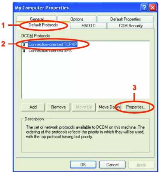
- Right-click on My Computer and then click Properties to access the Windows desktop properties,
- Click on the Default Protocols tab (1),
- Select Connection-oriented TCP/IP (2) then click on Properties... (3),
| Date: 2015-09-016T 8200-02h | INSTALLER MANUALCONFIGURATION TOOL DESCRIPTION |  |
- Select Internet Protocol Version 4 (TCP/IPv4) (4),
- Click Properties (5),
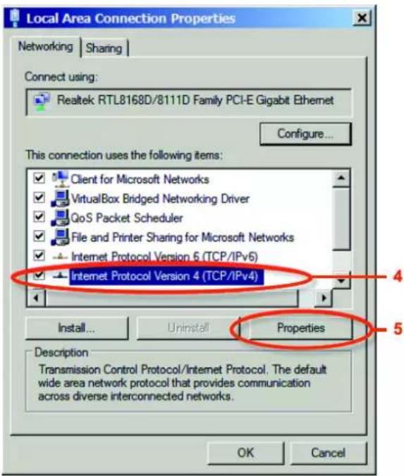
- Check the Use the following IP address box: (6),
- Provide the following items:
• IP address (7): 192.168.0.xxx (with xxx included between 2 and 252),
- Subnet mask (8): 255.255.255.0.
NOTE: If a firewall is active on the local network, the client traffic to the domovea server must be authorized. The domovea server uses the TCP port 4504 and UDP port 3702. The firewall must be properly configured to authorize incoming traffic through these ports.
- Click OK to accept the changes and then close all open windows.

| Date: 2015-09-016T 8200-02h | INSTALLER MANUALCONFIGURATION TOOL DESCRIPTION |  |
To connect the configuration tool to the domovea server:
- Start the configuration tool.
It finds all servers connected to the existing Ethernet network.
The domovea server is automatically recognized (9).
NOTE: If applicable, disable the wireless terminal which is installed the configuration tool.
- Select the domovea server (9),
- Click Connect (10).
If the domovea: server is not automatically detected:
- Provide the server's IP address (192.168.0.253) (11),
- Click Connect (12).


- The initialization icon appears. The configuration tool is ready for use.

| Date: 2015-09-016T 8200-02h | INSTALLER MANUALCONFIGURATION TOOL DESCRIPTION |  |
4.2 NAVIGATION INTERFACE
The navigation interface of the domovea configuration tool displayed below:
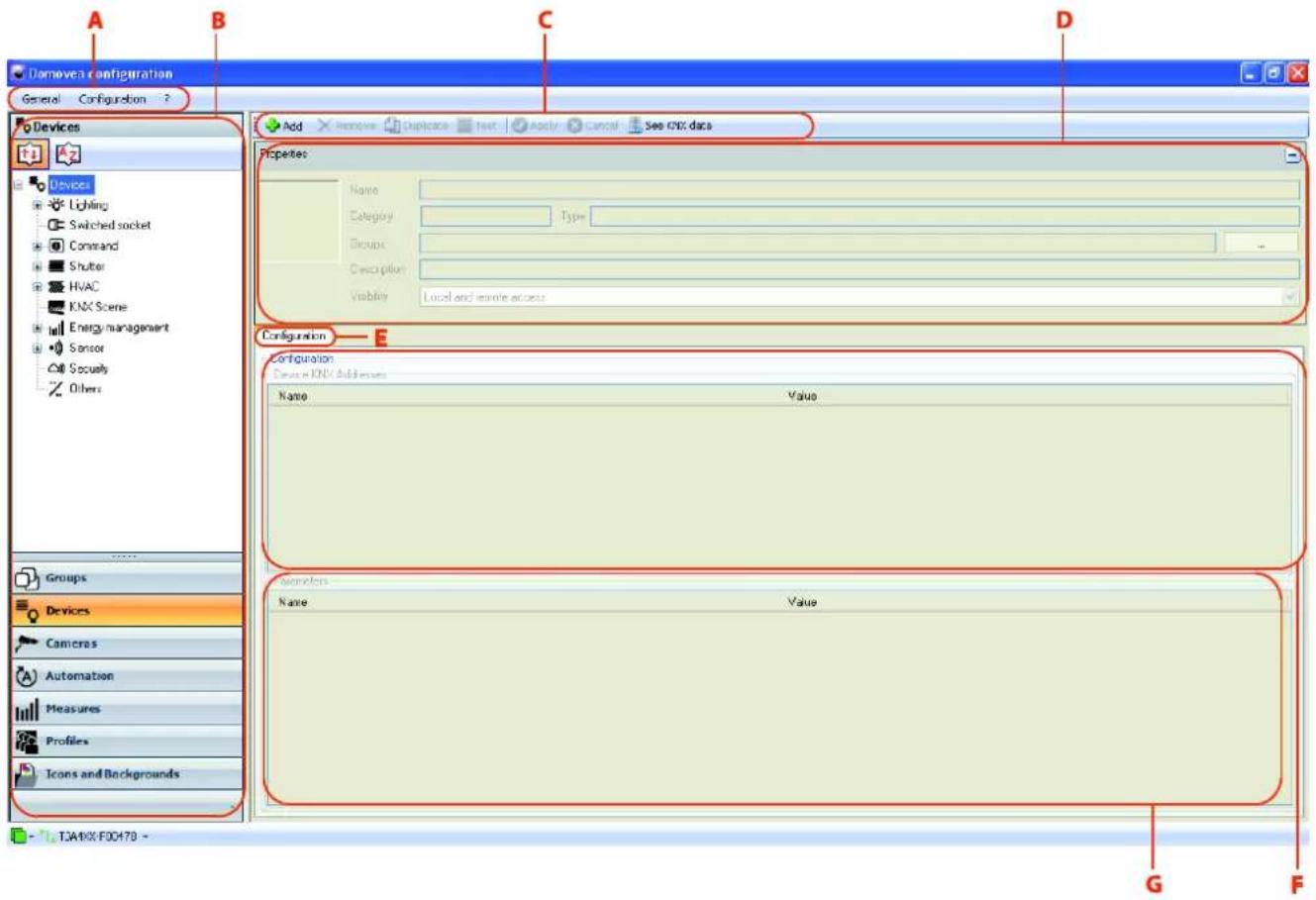
A: Main menu bar E: List of tabs
B: Link list F: Objects window
C: Menu bar G: Configuration window
D: Properties window
4.3 MAIN MENU
Select the General menu in the main menu bar.
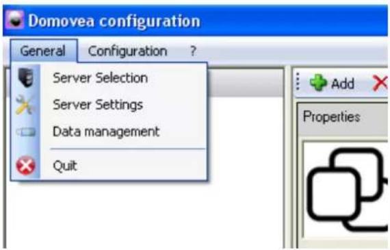
Server Selection:
Allows you to select a server. The selection is performed automatically at the configuration tool launch, but it is possible to select another one from this window.
Server Settings: Allows you to configure the server settings.

| Date: 2015-09-016T 8200-02h | INSTALLER MANUALCONFIGURATION TOOL DESCRIPTION |  |
KNX Connexion: Allows you to configure the KNX connection.
Configure the KNX clock...: Allows you to configure a synchronization KNX clock from which the date and time will be sent at regular, configurable intervals.
Sending frequency:
Used to define the sending frequency to the KNX bus
Possible value: 15min, 30min, 1h, 6h, 12h or every day
Sending format:
Used to define the sending format on the KNX bus
1 group address

1 KNX address for the date and time (8 octets)
2 group addresses

2 KNX addresses
One for the date (3 octets) and one for the time (3 octets)
Configure connection... : Enables the serial port used by the KNX/USB media coupler to be selected

Available ports: Enables the available ports to be selected.
Port used: Enables the name of the selected port to be entered.
State: Enables the device connection status to be entered.
Physical address: Displays the physical address of the device on the KNX bus.
Version: Displays the software version of the connected device.
| Date: 2015-09-016T 8200-02h | INSTALLER MANUALCONFIGURATION TOOL DESCRIPTION |  |
Configure address....: Allows you to set the physical address of the KNX interface (default value: 15.15.254).

Portal configuration: Allows you to set the domovea portal configuration (for more details, see "configuring remote access to the portal").
Mail and contacts: Allows you to set the e-mail and address book.
Mail configuration (SMTP): Allows you to set the email address used for transmitting email.
Mail From: Allows you to provide the email address used for sending emails.
Outgoing mail server (SMTP): Allows you to provide the address of the SMTP server used for sending emails.
Port: Allows you to select the port used for sending e-mails (default: 25).
User name: Allows you to provide the username used for authentication when sending emails.
Password: Allows you to provide the password used for authentication when sending emails.
Encryption protocol: Used to choose to use an encryption protocol or not to secure transactions made via Internet.

Contacts configuration: Allows you to manage the recipient list.
| Date: 2015-09-016T 8200-02h | INSTALLER MANUALCONFIGURATION TOOL DESCRIPTION |  |
Regional options:
Date and time properties:
Allows you to set the date (if no time server is available on the network). It also allows you to set the server geolocation to automatically calculate the sunrise and sunset time that will be displayed in the domovea client dashboard or to be used in the sequences.
Time server: Allows you to provide the appropriate address of the Internet time server.


NOTA : It is possible to change the time display mode (12/24 or AM / PM) from the profiles (see §.6.6)
Server: Displays the server resources and the error log. Restarting the server can also be performed from this interface.
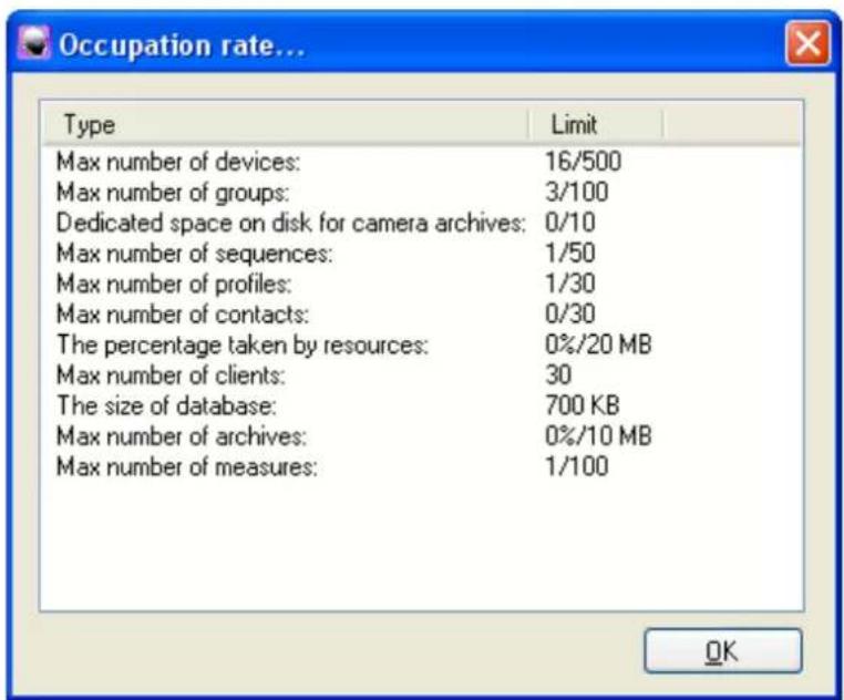
Occupation rate:
Number of devices, groups, cameras, sequences, profiles and contacts: indicates the number of resources used and the maximum number.
Occupation rate of icons and backgrounds: shows the percentage of space used and the maximum space available for storing backgrounds and icons.
Size of configuration data: shows the space used for storing configuration data.
Occupation rate of archives: shows the percentage of space used and the maximum space available for storing archives.
Data management: Allows you to manage the configuration of domovea projects. The configuration archive files have the.ddb format and their storage location is defined by the user during the backup operation.

Restore: Allows you to restore a previously saved configuration from the domovea server, from user-defined disk reader, or from the domovea portal.
Save: Allows you to save the current configuration on the domovea server, on a user-defined disk reader, or on the domovea portal.
NOTE: After each modification to the configuration, it is recommended to create a backup copy on the domovea server, as well as locally or on the domovea Web portal.
NOTE: The configuration backup on the domovea Web portal does not include the cameras' Measurements and Archives items.
| Date: 2015-09-016T 8200-02h | INSTALLER MANUALCONFIGURATION TOOL DESCRIPTION |  |
Reset: Allows you to start a new project configuration from a blank project. Saved data is not deleted.
Other actions: Delete: Deletes the selected archives.
Define as a reference archive: Allows you to set the selected archives as reference archives on the server or on the portal.
Display archive information: Displays the selected archive data.
Change data: Allows you to add a comment to the selected archive data.
NOTE: Five projects can be saved on the server. One of these archives can be declared as an reference archive. In this case, the reference archive will not be deleted during a server reboot.
Select the Configuration menu in the main menu bar.

Hexadecimal - 2 Levels - 3 Levels: Allows choosing the format of the KNX group addresses.
Confirmation Popup: Allows enabling/disabling the display of the confirmation popups that appear before committing changes.
Languages: Used to configure the domovea software language.
5. CONFIGURATION PROJECT EXAMPLE
5.1 DEFINING THE PROJECT STRUCTURE
To facilitate understanding, this chapter will use a specific example that represents the majority of cases.
Hosting example with different applications:
- Lounge (lighting ON / OFF, shutters up / down, thermostat setting).
- Kitchen (lighting ON / OFF, shutters up / down, Smoke detector, Ventilation ON / OFF).
- Outdoor (lighting ON / OFF, Gate operator / closing, Weather station).
Content of these three zones:
| LOUNGE:Lounge general lightingMood lightingReading lightLounge window blindTerrace shutter loungeHeating thermostat | KITCHEN:Kitchen general lightingKitchen worktop lightingSmoke detectorKitchen window blindKitchen terrace shutterVentilation | OUTDOOR:Outdoor lightingGate operatorWeather Station |
5.2 CREATING GROUPS
A group is a part of the installation consisting of a room, one floor of the building, one zone or one part of a set of rooms, floors or areas (for example: kitchen, lounge, outdoor).
The groups are the structure of the project (maximum 100 groups per installation)
| Date: 2015-09-016T 8200-02h | INSTALLER MANUALCONFIGURATION PROJECT EXAMPLE |  |
To create the Kitchen group:
- Select Groups (1) in the link list,
- Click on Add (2) in the menu bar and click New Group,
- Provide Kitchen in the Name field (3) of the Properties window,
- Click Apply (4) in the menu bar to complete the change.
NOTE: For more details about other fields in the Properties window, see §.6.1.
![Removea configuration General Configuration ? Groups My home Kitchen [updated] Add Remove Duplicate Apply Cancel Properties Name Kitchen Description Background None Current group items Groups Devices Cameras Automation Measures Profiles Icons and Backgrounds All items No files Devices Groups](/content/2026/06/1370333/images/b4a3a61758842c74cd819904afdbfaebf0d94d17514495f547bf8bd1463d926a.jpg)
| Date: 2015-09-016T 8200-02h | INSTALLER MANUALCONFIGURATION PROJECT EXAMPLE |  |
Create the Outdoor and Lounge groups following the same procedure. The project structure is shown below:

Select the Groups icon for the domovea client. The following page appears:

5.3 CREATING DEVICES
A device is an equipment unit connected to an element of a KNX installation which can be controlled or viewed via the domovea client such as lighting, blinds, heating, etc. (500 devices maximum per installation).
NOTE: domovea cannot access the data taken from installation products. Please verify that KNX products that you wish to add to domovea offer object formats which are compatible with domovea device objects.
To create the Kitchen general lighting:
- Select Devices (1) in the link list,
- Click on Add (2) in the menu bar and select the Lighting category and click on the Dimmer device,
- Enter Kitchen general lighting in the Name field (3) of the Properties window,
- Click Apply (4) in the menu bar to complete the change.
NOTE: For more details on the properties, objects and configuration windows, see §.6.2.
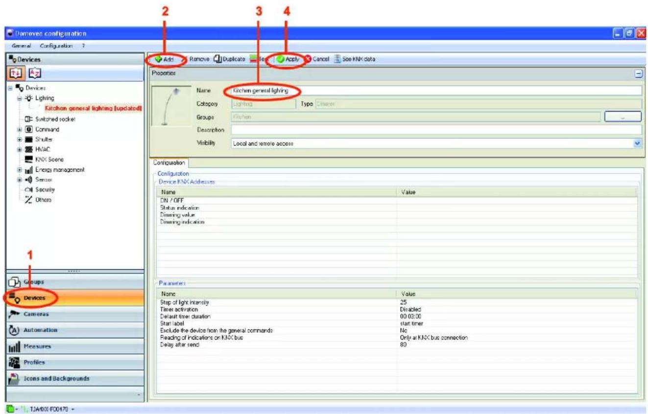
Create all devices previously defined (see §5.1) following the same procedure by associating the name of the device (3) to the type of device. The table below lists the names and types of devices to associate.
| Device name (3) | Category / type of device |
| Mood lighting | Lighting / Dimmer |
| General kitchen lighting | Lighting / Dimmer |
| Lounge general lighting | Lighting / Dimmer |
| Kitchen worktop lighting | Lighting / Light |
| Reading lighting | Lighting / Light |
| Outdoor lighting | Lighting / Light |
| Lounge window blind | Shutter / Extended Shutter / Blind |
| Kitchen window blind | Shutter / Extended Shutter / Blind |
| Lounge terrace shutter | Shutter / Extended Shutter |
| Kitchen terrace shutter | Shutter / Extended Shutter |
| Heating thermostat | HVAC / Thermostat |
| Smoke detector | Sensor / Binary input |
| Ventilation | Command / ON / OFF |
| Gate operator | Command / Pulse |
| Weather Station | Sensor / Weather Station |
5.4 ASSIGNING A DEVICE TO A GROUP
All devices appear in the Groups link in the same tree level as the Kitchen, Lounge and Outdoor groups.
![Domovea configuration General Configuration 7 Groups My home [10] Kitchen Lounge Outdoor Heating thermocostal Kitchen general lighting Kitchen terrace shutter Kitchen window blind Lounge general lighting Lounge terrace shutter Lounge window blind Mood lighting Outdoor lighting Gate operator Reading light Smoke detector Ventilation Weather station Kitchen workshop lighting Properties Name Myhome Description Background None Current group item Kitchen Lounge Outdoor Heating thermocostal Kitchen general lighting Kitchen terrace shutter Kitchen window blind Lounge general lighting Lounge terrace shutter Lounge window blind Moodlighting Outdoor lighting Gate operator Pleading light Smoke detector Ventilation Weather station Kitchen workshop lighting Groups Devices Cameras Automation Measures Profiles Icons and Backgrounds All items (15) All items (16) Heating thermocostal Kitchen general lighting Kitchen terrace shutter Kitchen window blind Lounge general lighting Lounge terrace shutter Lounge window blind Mood lighting Outdoor lighting Gate operator Reading light Smoke detector Ventilation Weather station Kitchen workshop lighting Lighting (8) Command (2) Shakes (4) HVAC (1) Sensor (2) Groups (3) Kitchen Loungo Outdoor](/content/2026/06/1370333/images/1c989e6a05574d93bf5f4bc4285d35323070345f00e40207be5ab7a2fe9d88bb.jpg)
| Date: 2015-09-016T 8200-02h | INSTALLER MANUALCONFIGURATION PROJECT EXAMPLE |  |
To assign a device to its group:
- Drag/drop the device (Kitchen general lighting in this case) (1) into the group (Kitchen in this case) (2).

- Assign all devices in their respective groups following the same procedure and according to the structure defined previously (see §5.1). The project structure is shown below:

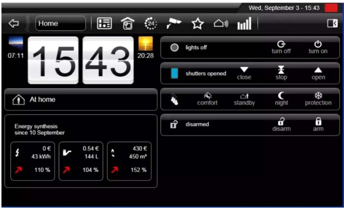
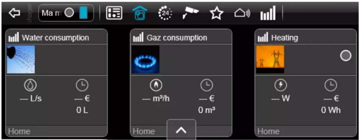
Select the Dashboard icon on the domovea client. The following page appears:
- Select the Groups icon 📋 on the domovea client. The following page appears:
| Date: 2015-09-016T 8200-02h | INSTALLER MANUALCONFIGURATION PROJECT EXAMPLE |  |
5.5 CREATING KNX LINKS
Export the Project created in TX100 or ETS then import this project in the configuration tool to set the KNX links.
5.5.1 ETS PROJECT
Exporting an ETS project
Export OPC (esf file):
From ETS, it is possible to export an OPC file containing all the group's addresses information.
To export an esf file:
- Click on Extras and then click Export OPC in the menu bar and select the path to save the file.

Export xml (xml file):
It is also possible to export the list of group addresses in xml format.
To export an xml file:
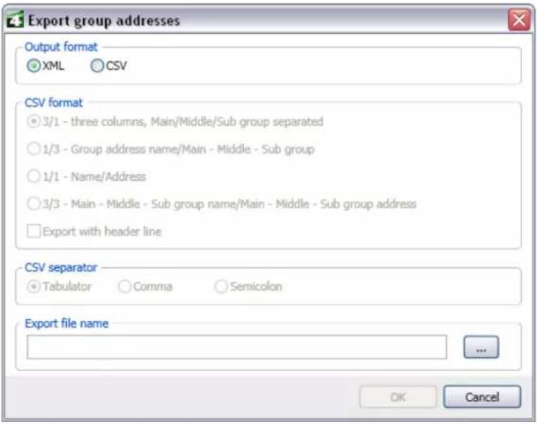
- Right-click on the list of group addresses and then click Export Group Addresses.

| Date: 2015-09-016T 8200-02h | INSTALLER MANUALCONFIGURATION PROJECT EXAMPLE |  |
- Select XML format and then provide the backup file's path.
Importing an ETS project
To import an ETS project:
- Select Devices (1) in the link list,
- Click on See KNX data (2) in the menu bar and select Configured by ETS.

| Date: 2015-09-016T 8200-02h | INSTALLER MANUALCONFIGURATION PROJECT EXAMPLE |  |
- Click ETS Import (3).

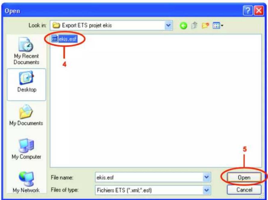
- Select the current project's ETS export file in .esf format (4),
- Click Open (5).
| Date: 2015-09-016T 8200-02h | INSTALLER MANUALCONFIGURATION PROJECT EXAMPLE |  |
The project created in ETS is displayed in the ETS Import window (6):

| Date: 2015-09-016T 8200-02h | INSTALLER MANUALCONFIGURATION PROJECT EXAMPLE |  |
Associating a KNX group address to a device output
Associate the KNX group addresses created with ETS to a command or a device status indication in the domovea configuration.
To associate the KNX group addresses with the Lighting device outputs:
- Select Devices (1) in the link list,
- Create the Lighting set and then select the Kitchen general lighting device (2),
- Create the Lighting sets (3), cmd (4), and ie (5) in the KNX data import window.
NOTE: the cmd abbreviation stands for command, and ie stands for status indication.
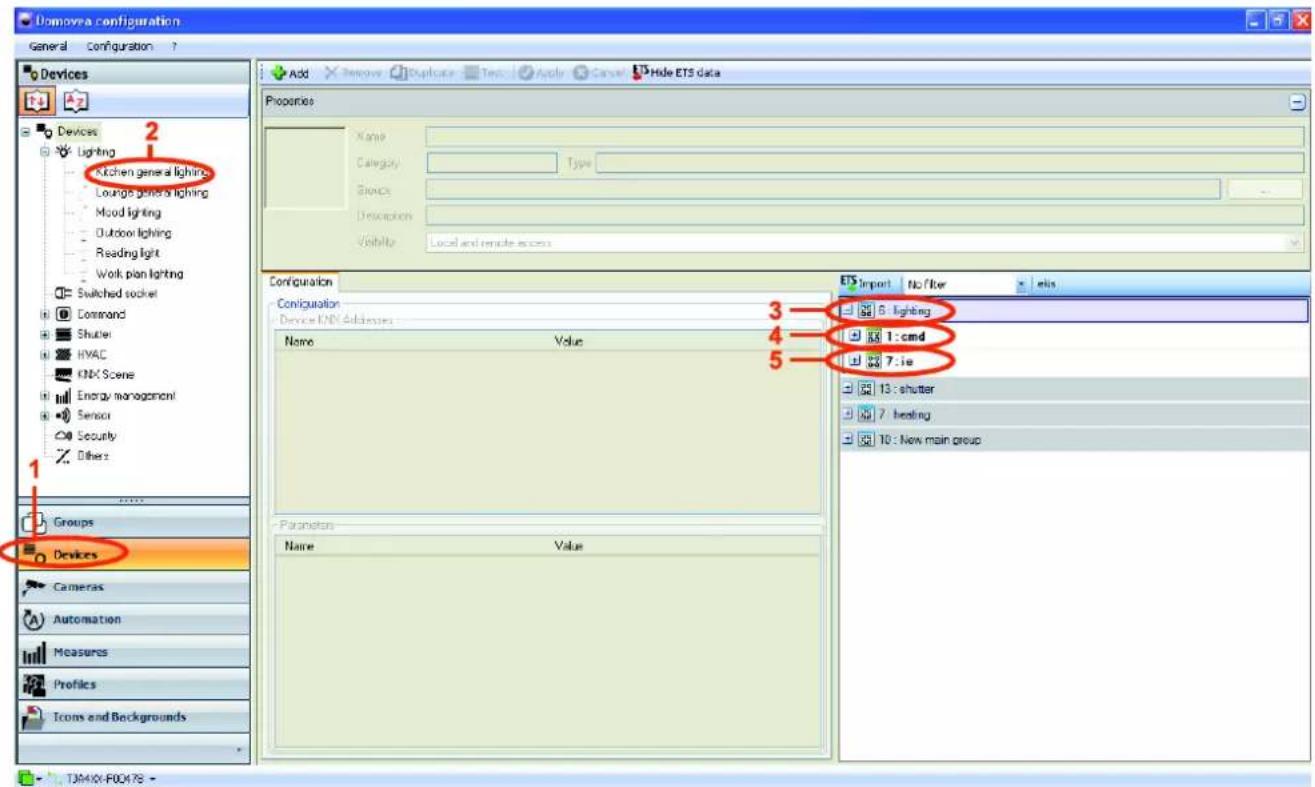
- Select TXA213 - output 1 (6) in the cmd set (4) and then drag and drop it from this output into the ON / OFF command value field (7).
NOTE: The TXA213 indicates the domovea installation dimmer module.
- Select TXA213 - output 1 value (8) and then drag and drop it from this output into the Dimming command value field (9).
NOTE: You can also provide directly the KNX group address, visible in the ETS export in the objects window value field. For example, for the ON / OFF command, you can provide directly the address 6/1/11 in the associated value field. Likewise, for the dimming command value, you can provide directly the address 6/1/11 in the associated value field.

- Select TXA213 - output 1 (10) in the ie set (5) and then drag and drop it from this output into the status indication value field (11).
- Select TXA213 - output 1 value (12) and then drag and drop it from this output into the Dimming indication value field (13).

- Select the Groups icon 📋, the Lounge group, and then Mood lighting device on the domovea client. Objects previously defined in the configuration utility are displayed on the client:
- The turn on / turn off command (7) with its Dimming status indication (11),
- The Dimming value command (9) with the Dimming indication value (13).

- Provide the KNX group addresses of the Kitchen general lighting and Lounge general lighting devices following the same procedure and using the outputs 2 and 3 of the TXA213.
To associate the KNX group addresses to the Outdoor lighting device outputs:
- Select Devices in the link list,
- Create the Lighting set and then select the Outdoor lighting device,
- Select TXA206 - output 1 (14) in the Lighting set, then cmd and drag and drop it from this output into the ON / OFF command value field (15).
NOTE: The TXA206 indicates the domovea installation lighting module.

- Select TXA206 - output 1 (16) in the ie set and then drag and drop it from this output into the Status indication value field (17).
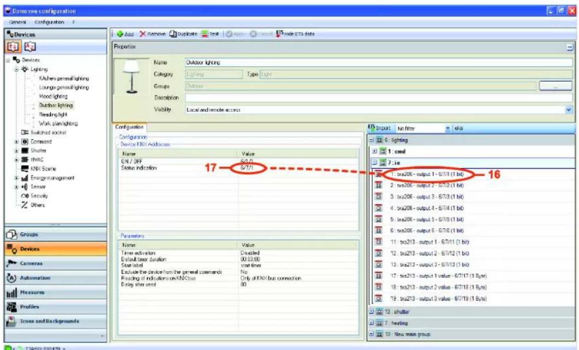
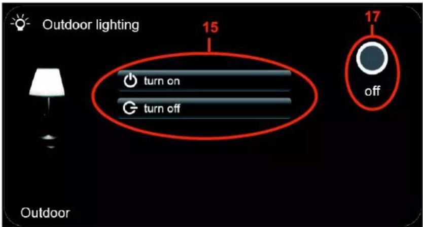
- Select the Groups icon 📄, the Lounge group, and then Outdoor lighting device on the domovea client. Objects previously defined in the configuration utility are displayed on the client:
- The turn on / turn off command (15) with its lighting status indication (17).
- Provide the KNX group addresses of the Reading light and Kitchen worktop lighting devices following the same procedure and using the outputs 2 and 3 of the TXA206.
To associate the KNX group addresses to the Heating thermostat device outputs:
- Select Devices in the link list,
- Create the HVAC set and then select the Heating thermostat device,
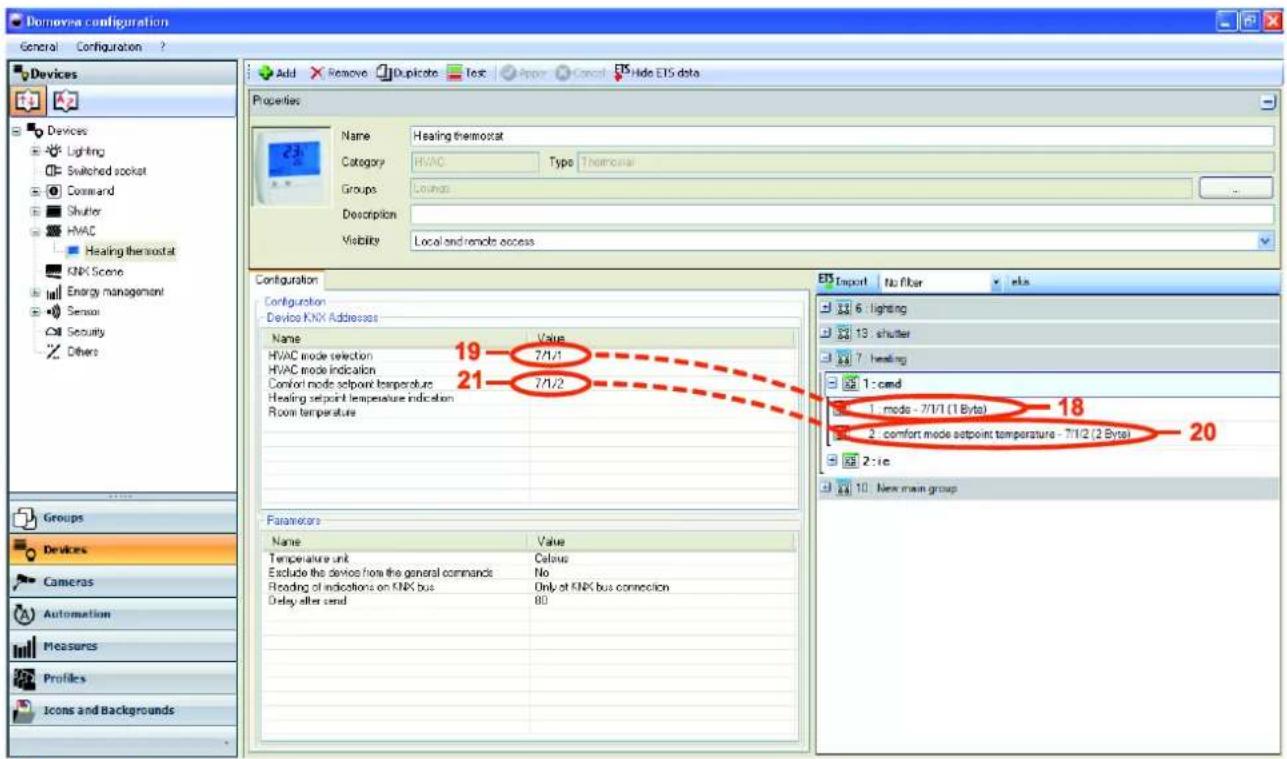
- Select mode (18) in the heating set, then cmd and drag and drop it from this output into the HVAC mode selection command value field (19).
- Select comfort mode setpoint temperature (20) and then drag and drop it from this output into the comfort setpoint temperature setting command value field (21).
1J9401-F00478
- Select room temperature (22) in the ie set and then drag and drop it from this output into the room temperature indication value field (23).
- Select mode (24) and then drag and drop it from this output into the HVAC mode indication value field (25).
- Select setpoint temperature (26) and then drag and drop it from this output into the Heating setpoint temperature indication value field (27).

| Date: 2015-09-016T 8200-02h | INSTALLER MANUALCONFIGURATION PROJECT EXAMPLE |  |
- Select the Groups icon 📋, the Lounge group, and then Thermostat device on the domovea client. Objects previously defined in the configuration utility are displayed on the client:
• The Mode Selection (19) with its status indication of the Current mode (25),
- The Temperature Setting of the Comfort Setpoint Temperature (21) with its status indication (27),
• The Room Temperature indication (23).

To associate the KNX group addresses to the Kitchen terrace shutter outputs:
- Select Devices in the link list,
- Create the Shutter set and then select the Kitchen terrace shutter device,
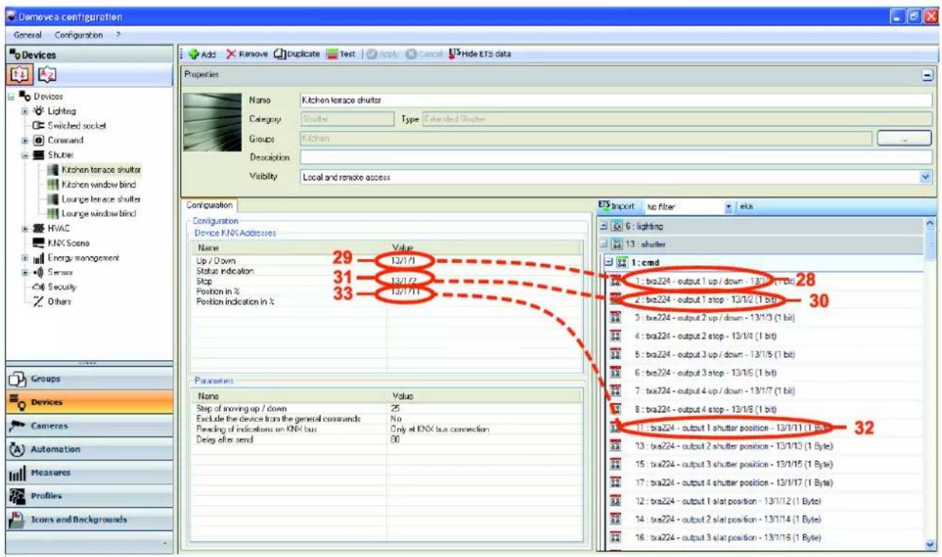
- Select TXA224 - output 1 up / down (28) in the shutters set, then cmd and drag and drop it from this output into the Up / Down command value field (29).
NOTE: The TXA224 indicates the domovea installation shutter / blind module.
- Select TXA224 - output 1 stop (30) and then drag and drop it from this output into the Stop command value field (31).
- Select TXA224 - output 1 shutter position (32) and then drag and drop it from this output into the Position in % command value field (33).
-1, T2A4XX-F00H78 -
- Select TXA224 - output 1 shutter position (34) in the ie set and then drag and drop it from this output into the Position indication in % value field (35).

- Select the Groups icon 📋, the Kitchen group, and then Kitchen terrace shutter device on the domovea client. Objects previously defined in the configuration utility are displayed on the client:
- open / close commands (29),
- stop command (31),
- shutter position command (33).

- Provide the KNX group addresses of the device Lounge terrace shutter device following the same procedure and using the output 2 of the TXA224.
To associate the KNX group addresses to the Kitchen window blind outputs:
- Select Devices in the link list,
- Create the Shutter set and then select the Kitchen window blind device,
- Select TXA224 - output 3 up / down (36) in the shutters set, then cmd and drag and drop it from this output into the Up / Down command value field (37),
- Select TXA224 - output 3 stop (38) and then drag and drop it from this output into the Stop command value field (39),
- Select TXA224 - output 3 shutter position (40) and then drag and drop it from this output into the Position indication in % command value field (41),
- Select TXA224 - output 3 slat position (42) and then drag and drop it from this output into the Slat angle in ° command value field (43).

| Date: 2015-09-016T 8200-02h | INSTALLER MANUALCONFIGURATION PROJECT EXAMPLE |  |
- Select TXA224 - output 3 shutter position (44) in the ie set and then drag and drop it from this output into the Position indication in % value field (45).
- Select TXA224 - output 3 slat position (46) and then drag and drop it from this output into the Slat angle indication in ° value field (47).

| Date: 2015-09-016T 8200-02h | INSTALLER MANUALCONFIGURATION PROJECT EXAMPLE |  |
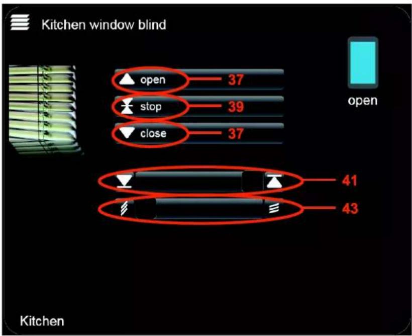
- Select the Groups icon 📄, the Kitchen group, and then Kitchen window blind device on the domovea client. Objects previously defined in the configuration utility are displayed on the client:
- open / close commands (37),
- stop command (39),
• blind position command (41),
• blind slat angle command (43),
- Provide the KNX group addresses of the device Lounge window blind device following the same procedure and using the output 4 of the TXA224.
To associate the group KNX addresses to the Weather station status indications:
- Select Devices in the link list,
- Create the Sensor set and then select the Weather station device,
- Provide the KNX 10/1/1 group address in the temperature status indication value field,
- Provide the KNX 10/1/2 group address in the wind speed status indication value field,
- Provide the KNX 10/1/3 group address in the brightness status indication value field,
- Provide the KNX 10/1/4 group address in the rain status indication value field,
- Select the Groups icon 📋, the Outdoor group, and then Weather station device on the domovea client. Objects previously defined in the configuration utility are displayed:
• The temperature status indication (48),
• The wind speed status indication (49),
• The brightness status indication (50),
• The no rain status indication (51),

bar
| Condition | Temperature (°C) | Frequency | |---|---|---| | Weather station | 23.6 | 48 | | Outdoor | | | | 10,8 km/h | | 49 | | Outdoor | | 50 | | no rain | | 51 || Date: 2015-09-016T 8200-02h | INSTALLER MANUALCONFIGURATION PROJECT EXAMPLE |  |
To associate the group KNX addresses to the Ventilation command:
NOTE: In this example, input 1 of the TXA306 module of the domovea installation is used.
- Select Devices in the link list,
- Create the Command set and then select the Ventilation device,
- Provide the KNX 9/1/1 group address in the restart / off command value field,
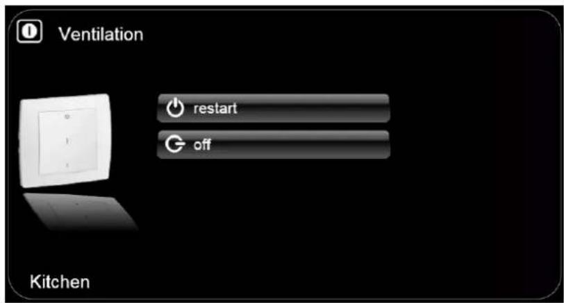
- Select the Groups icon 📋, the Kitchen group, and then Ventilation device on the domovea client. The ON / OFF command previously defined in the configuration utility is displayed:
To associate the group KNX addresses to the Gate operator command:
NOTE: In this example, input 2 of the TXA306 module of the domovea installation is used.
- Select Devices in the link list,
- Create the Command set and then select the Gate operator device,
- Provide the KNX 9/1/2 group address in the ON / OFF command value field,
- Select the Groups icon 📄, the Outdoor group, and then Gate operator device on the domovea client. The pulse command previously defined in the configuration utility is displayed:

To associate the KNX group addresses to the of Smoke detector status indication:
NOTE: In this example, input 3 of the TXA206A module of the domovea installation is used.
| Date: 2015-09-016T 8200-02h | INSTALLER MANUALCONFIGURATION PROJECT EXAMPLE |  |
- Select Devices in the link list,
- Create the Sensor set and then select the Smoke detector device,
- Provide the KNX 6/7/3 group address in the Status indication value field,
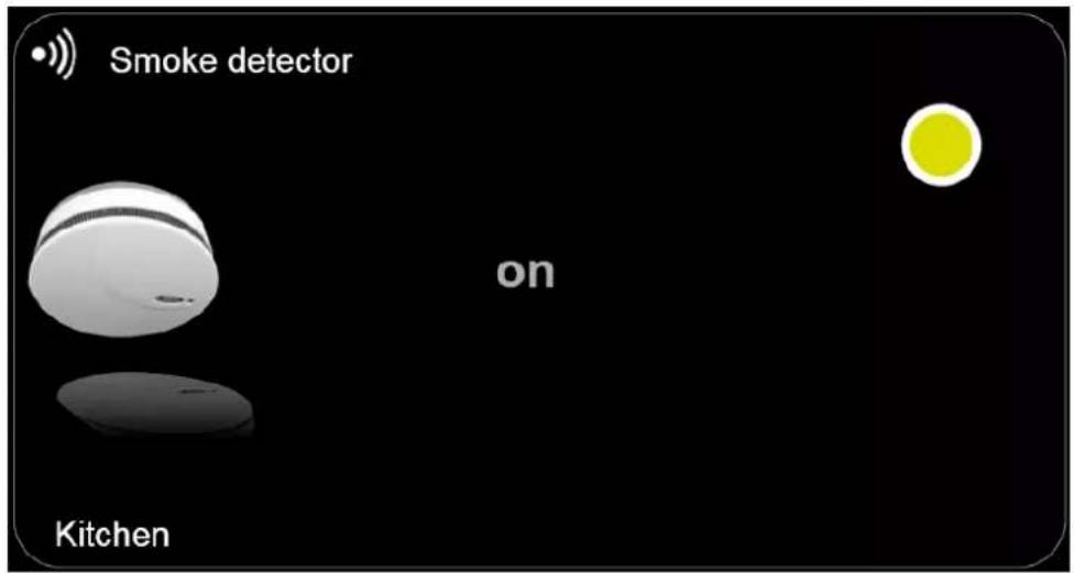
- Select the Groups icon 📄, the Kitchen group, and then Smoke detector device on the domovea client. The status indication previously defined in the configuration utility is displayed:
5.5.2 PROJECT TXA100
To import a TXA100 project, click on "General" in the menu bar, then on "Import TXA100 data". The domovea configuration will then be automatically created, resulting in a database containing groups and devices (including group addresses and adequate settings). For more information, please refer to the TXA100 documentation.
| Date: 2015-09-016T 8200-02h | INSTALLER MANUALCONFIGURATION PROJECT EXAMPLE |  |
5.6 CURVES (SENSORS)
The Sensor curve function is used to display the evolution of the some sensor values over a given period :
- Temperature
- CO2
- Wind
- Luminosity
- Humidity
- Configurator view (example with thermostat)
A Thermostat (1) can be added in the HVAC category in the configurator. To make it clearer, it can be renamed by modifying the Name field (2).
- Click on Oui (3) (Yes) to save.

Compatible devices:
- Thermostat
o Thermometer
o Weather station
o Luminosity sensor
o Humidity sensor
o CO2 sensor
| Date: 2015-09-016T 8200-02h | INSTALLER MANUALCONFIGURATION PROJECT EXAMPLE |  |
- Client view
- Display the "Devices" view using the icon (4).
- Select the device to view

In this example the thermostat salon (sitting room thermostat) is selected.
- Click on the icon (5) to display the temperature curve.

The temperature curve for the sitting room is shown for an entire day.

| Date: 2015-09-016T 8200-02h | INSTALLER MANUALCONFIGURATION PROJECT EXAMPLE |  |
5.6.1 DIFFERENT TYPES OF COMPARISON
- Value comparison:
To compare the temperature values with other rooms, select the (6) icon.
A window opens.
- Select Value comparison and one or more thermostats in different rooms.
In this example, the comparison is made with the station météo (weather station) and the thermostat chambre (bedroom thermostat).

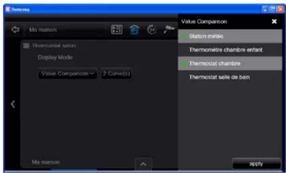
In this example, the station météo (weather station) is deselected by clicking on the tab (7) to compare just the two thermostats.
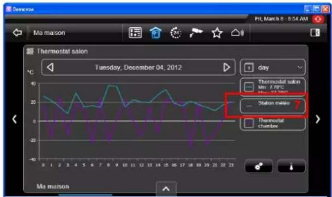
By clicking on the curve, a pop-up opens showing the temperature at 3pm in the sitting room, the bedroom and outside.
It also gives the minimum and maximum temperatures, plus the average temperature for the day obtained by the following formula: average = (minimum temperature + maximum temperature) / 2.

| Date: 2015-09-016T 8200-02h | INSTALLER MANUALCONFIGURATION PROJECT EXAMPLE |  |
- Time comparison:
To compare temperature values in relation to a set date or over a sliding period. For this example:
- Select Time comparison, then Fixed date, and select the date using the + and - signs.
- Click on apply.


The temperature curves are displayed for the period between 3rd and 4th December.

By clicking on the curve, a pop-up opens with the temperature comparison for 3rd and 4th December at 9am in the sitting room.

- Choosing a period:
- Click on the icon (8) to choose the period,
- Select "week" (9) for this example.


The temperature curves are shown for one week.

The screens below show energy consumption:
- over 1 month

- over 1 year.

| Date: 2015-09-016T 8200-02h | INSTALLER MANUALCONFIGURATION PROJECT EXAMPLE |  |
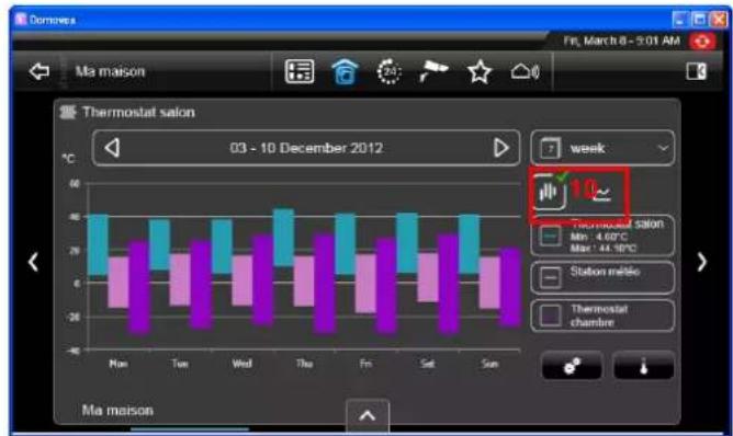
• STANDARD DEVIATION display:
The weeks, months and years views can also be displayed in "standard deviation" mode. This mode shows the differences between the average minimum and maximum temperatures for each day.
- To switch between the displays, click on the icon (10).
6. CONFIGURATION TOOL ADVANCED FUNCTIONS
6.1 GROUPS
When creating a Group (see §.5.1.1), it is possible to fill additional fields in the Properties window:
- Description (1): Allows you to describe the group in detail.
- Background (2): Allows you to select a background that will be visible on the domovea client by accessing the group.
- Icon (3): Allows you to customize the icon. Click on the icon, double-click on the icon you wish to be in the icon list and then click Apply in the menu bar to confirm the changes.

6.2 DEVICES
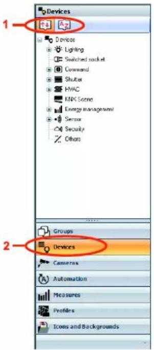
The buttons on the tool bar (1) of the Devices link (2) allows modifying the display of the set of devices according to various criteria:
- ↑↓ : Allows you to sort devices by category (lighting, shutter, sensor, etc.).
- : Allows you to sort the devices alphabetically,
| Date: 2015-09-016T 8200-02h | INSTALLER MANUALCONFIGURATION TOOL ADVANCED FUNCTIONS |  |
When creating a Device (see §.5.1.2), it is possible to fill additional fields in the Properties window:
- Groups (...) (3): Allows assigning the device to one or more groups.
- Description (4): Describes the device in detail.
- Visibility (5): Three visibility options available:
Local and remote access: Provides access to the device or the automation with the domovea client and via the www.domovea.com portal.
Local access: Provides access to the device only with the domovea client.
Never: Prevents access to the device with the domovea client and via the www.domovea.com portal.
- Icon (6): Allows you to customize the icon. Click on the icon, double-click on the icon you wish to be in the icon list and then click Apply in the menu bar to confirm the changes.
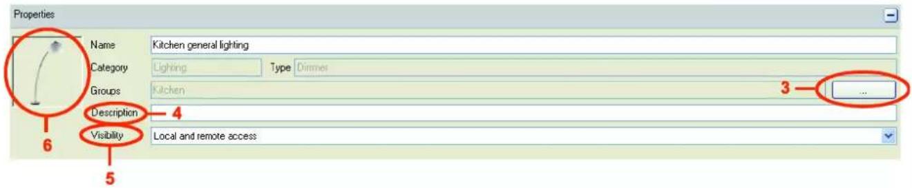
To assign the device to one or more groups, click on the Groups button (3). Now you can find pre-defined groups. Check the box of the group or groups to which the device must be assigned.

6.3 CAMERAS
This section describes how to create a link between a network camera and a domovea installation (10 cameras maximum per installation).
The following list shows the brands and models of the cameras supported:
| Brand | Model |
| Axis | 207 |
| 207MW | |
| 209FD | |
| 209MFD | |
| 210 | |
| 211 | |
| 211M | |
| 212PTZ | |
| 213PTZ | |
| 214PTZ | |
| 215PTZ | |
| 216FD | |
| 216MFD | |
| 221 | |
| 223M | |
| 225FD | |
| 231D+ | |
| 232D+ | |
| 233D | |
| 24xQ(A) Series | |
| 24xS(A) Series | |
| M1013 | |
| M1014 | |
| M1033-W | |
| M1034-W | |
| M1054 | |
| M10xx Series | |
| M1114 | |
| M3004-V | |
| M3005-V | |
| M3006-V | |
| M3011 | |
| M3014 | |
| M3203 | |
| M3204 | |
| M5013 | |
| M5014 | |
| M7001 |
| Brand | Model |
| Axis | P1204 |
| P1214 | |
| P13xx Series | |
| P3301 | |
| P3343 | |
| P3344 | |
| P3346 | |
| P5512 | |
| P5534 | |
| Q1755 | |
| Q6032 | |
| Q6034 | |
| Q6035 | |
| Q7401 | |
| Q7404 | |
| D-Link | DCS-1130 |
| DCS-2100 | |
| DCS-2120 | |
| DCS-2121 | |
| DCS-2130 | |
| DCS-2132L | |
| DCS-2210/DCS-2230 | |
| DCS-2310L | |
| DCS-3200 | |
| DCS-3420 | |
| DCS-5300 | |
| DCS-5605 | |
| DCS-7xxx Series | |
| DCS-900 | |
| DCS-930L | |
| DCS-932 | |
| DCS-942L | |
| DCS-950G |
| Brand | Model |
| Mobox | D12 |
| D22 | |
| D24 | |
| D25 | |
| M12 | |
| M22 | |
| M24 | |
| M25 | |
| Q22 | |
| Q24 | |
| Q25 | |
| S14 | |
| T24 | |
| T25 | |
| Panasonic | BL-xxx PTZ series |
| BL-xxx Series | |
| WV-xxx PTZ series | |
| WV-xxx series | |
| Sony | SNC-CH160 |
| SNC-CHxxx Series | |
| SNC-CSxxP Series | |
| SNX-CX600W | |
| SNC-DFxxP Series | |
| SNC-DHxxx Series | |
| SNC-EM632R | |
| SNC-EP580 | |
| SNC-Px Series | |
| SNC-Rx550P Series | |
| SNC-RZxxN Series | |
| SNC-RZxxP Series | |
| SNC-VM600B | |
| SNC-XM632 | |
| SNC-Z20P Series |
| Date: 2015-09-016T 8200-02h | INSTALLER MANUALCONFIGURATION TOOL ADVANCED FUNCTIONS | :hager |
| Brand | Model |
| Vivotek | 21xx Series |
| 31xx PTZ series | |
| 31xx Series | |
| 61xx PTZ Series | |
| 61xx Series | |
| 7142 | |
| 71xx PTZ Series | |
| 71xx Series | |
| 7330 | |
| 813x Series | |
| BB5116 | |
| BB5315 | |
| CC8130 | |
| FD8131 | |
| FD8133/FD8134 | |
| FD8135H | |
| FD8136 | |
| FD8162 | |
| IP8132/IP8133 | |
| IP8332 | |
| IP8362 | |
| MD7560D | |
| PD8136 | |
| PT8133 | |
| PZ7151/7152 | |
| PZ8111 | |
| PZ8121 | |
| SD8111 | |
| SD8121 | |
| SD8311E | |
| SD8321E |
6.3.1 CREATING A LINK WITH A CAMERA
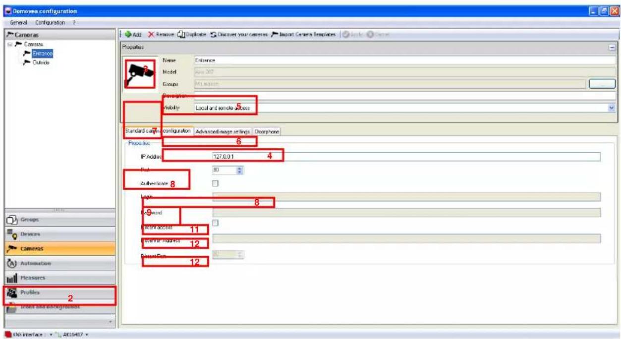
To create a link between a camera and the domovea system:
- Select Cameras (1) in the list of links,
- Click on Add (2) in the menu bar, then select the brand and model of the camera,
-
Fill in the following fields in the properties window:
-
Name (3): Allows you to name the camera.
• Description (4): Allows you to describe the camera more precisely. - Visibility (5): There are three visibility options available:
Local and remote access: Allows access to the camera with the domovea client and via the www.domovea.com web portal.
Local access: Allows access to the camera with the domovea client only.
No access: Prevents access to the camera with either the domovea client or through the www.domovea.com web portal.
- Icon (6): Allows you to customize the icon. Click on the icon, then double-click on the desired icon in the list of icons.
In the Standard camera configuration tab (7):
○ In local mode (in your local network)
IMPORTANT: the camera must be authorized on the network and its ports must be open.
- Enter the IP address of the camera (8),
- Enter the port (9) used by the camera,
- Check the Authenticate box (10) if authentication is required, then enter the login for connection (11) and the password (12) for the camera,
- Click on Apply to confirm the modifications.
Two additional tabs are available for more advanced camera settings:
- Advanced image settings: Allows more advanced configuration of the image settings, such as quality, compression, fluidity, etc.
- Doorphone: See doorphone chapter.
| Date: 2015-09-016T 8200-02h | INSTALLER MANUALCONFIGURATION TOOL ADVANCED FUNCTIONS |  |
- In distant access mode
If the box is not checked, the cameras will be visible in distant access mode (domovea.com web portal or mobile applications) with a refresh rate of just one image per minute.
If the box is checked, the user will be able to view a video flow from mobile applications (but not from the domovea.com web portal)
IMPORTANT: the camera must be authorized to communicate to the internet and the ports used must be redirected.
- Enter the distant IP address of the camera,
- Enter the distant port of the camera.
6.3.2 DASHBOARD
To display the cameras on the dashboard, please refer to the Profiles chapter.
| Date: 2015-09-016T 8200-02h | INSTALLER MANUALCONFIGURATION TOOL ADVANCED FUNCTIONS |  |
6.3.3 IMPORTING A CAMERA TEMPLATE
The cameras compatible with domovea are given in the previous list (see §.6.3). Nevertheless, as the market for this type of product is constantly developing, Hager will supply templates for other cameras from the six compatible brands. The corresponding configuration files will be available on the www.domovea.com web portal and will be renewed each time the software is updated.
To import a new camera template:
- Download the configuration file on the www.domovea.com web portal.
- Select Cameras (1) in the list of links,
- Click on Import camera templates (2) in the menu bar,
- Select the file with the extension .exam then click on Open.

Once this procedure has been performed, you can select your camera from the list of new camera templates among the six compatible brands.
6.3.4 DOORPHONE
A video doorphone may be created (without the audio function) using any camera by activating the function in the doorphone tab.
It is also possible to create a door entry system IP with audio function by adding an ELCOM brand camera.
For more details, see "Doorphone" document.
6.4 AUTOMATION
6.4.1 SEQUENCES
A sequence is a list of actions to perform on one or more elements of an electrical installation.
These actions can be performed according to various events such as pressure on the touch screen or pressing a bell.
For more details, see the "Sequences" document.
6.4.2 PROGRAMS
A program is a list of actions to perform on one or more elements of an electrical installation. These actions are based on a time range.
For more details, see the "Programming" document.
6.4.3 MEASUREMENTS
The domovea power display function responds to a growing desire to reduce energy needs.
After the different KNX products acquire data, it is transmitted to the domovea server through the KNX TP bus.
The domovea software and server archive this data, which after processing, will be displayed on a display device (touch screen, laptop, etc.).
For more details, see the "Energy" document.
6.4.4 PROFILES
This section describes how to create profiles to customize the appearance and access rights of the various clients in the system (a maximum of 30 profiles per system).
E.g. 1: In a family home, the young son must have access to his bedroom but not to the other rooms.
E.g. 2: In a hotel, it is important for the receptionist to be able to manage all the rooms, but a guest in room "X" must not be able to access or modify the parameters of room "Y". The guest must not even be able to view them.
To create a profile:
- Select Profiles (1) in the list of links,
- Click on Add (2) in the menu bar,
- Enter the Name (3) to be given to the profile in the properties window,
- Fill in the Description (4) field in the properties window to give a more detailed description of the profile.
In the Configuration tab and then in General settings (5) choose:
| Date: 2015-09-016T 8200-02h | INSTALLER MANUALCONFIGURATION TOOL ADVANCED FUNCTIONS |  |
- The Language used by the client,
- The format of the time display (0-24, AM/PM)
- The Default group to select the first level view,
- The Temperature sensor to select the temperature sensor used,
- Use the following sort for groups and devices to select the way elements are displayed (by category, in alphabetical order or customized (see § Customized sort display mode)),
- Enable confirmations to enable confirmation messages,
- Background image to select a background image.
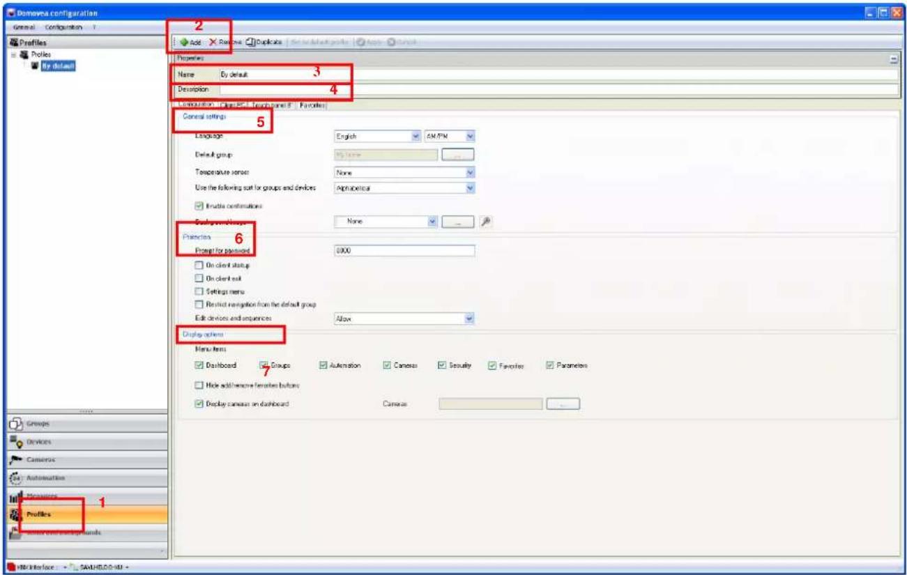
Password protection for access to certain functions can be defined in the Configuration tab, then in Protection (6):
Prompt for password allows you to define the password to be used:
- on client startup,
- on client exit,
- when accessing the settings menu,
- to restrict navigation from the default group,
It is also possible to authorise or prevent users from using the edit devices and sequences option.
The appearance of the client tool bar domovea can be defined in the Configuration tab then in Display options (7):
| Date: 2015-09-016T 8200-02h | INSTALLER MANUALCONFIGURATION TOOL ADVANCED FUNCTIONS |  |
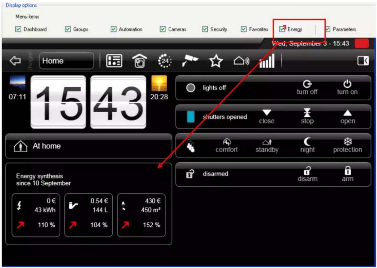
Menu items: Allows you to select your choice of favorite buttons that will be visible on the domovea client (Dashboard, Groups, Automation, Cameras, Security, Favorites, Energy, Settings).
| Date: 2015-09-016T 8200-02h | INSTALLER MANUALCONFIGURATION TOOL ADVANCED FUNCTIONS |  |

You can also display the image of one or more cameras on the dashboard:
- Check "Display cameras on dashboard" (1),
- Select the Outside and Entrance cameras (2).

| Date: 2015-09-016T 8200-02h | INSTALLER MANUALCONFIGURATION TOOL ADVANCED FUNCTIONS |  |
The energy overview may be viewed on the dashboard:
- Check "Energy" (3) in display options in the configurations.
Client PC display mode
The Client PC tab (8) allows configuration of the client domovea program operating on the PC.

Default view for groups/sequences/cameras: Allows the default display mode to be defined for the groups/sequences/cameras (ribbon, list, scheduler, mosaic).
Footer bar visibility: Display or not of the toolbar which appears at the bottom of the screen in client view.
Size of items: Allows the size of items to be selected.
Screen type: Selection of simple screen or touchscreen use.
Fullscreen mode: Allows full-screen mode to be selected for start-up,
Screen sensibility: allows definition of the scroll sensitivity,
Touch panel display mode 8"
The Touch panel 8" tab (9) enables configuration of the domovea program operating on the touch panel 8" (TJD080).
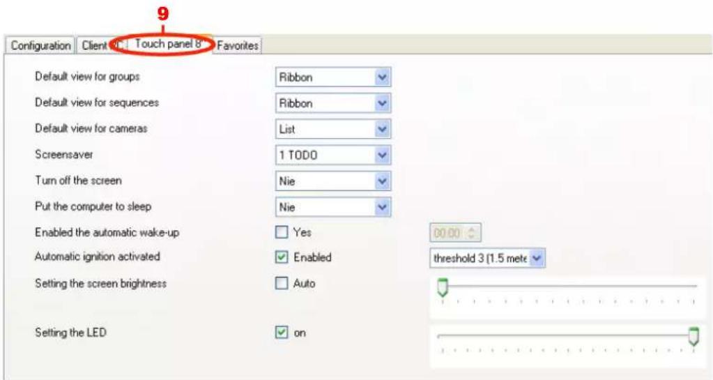
Default view for groups/sequences/cameras: Allows the default display mode to be defined for the groups/sequences/cameras (ribbon, list, scheduler, mosaic).
Screensaver/Turn off screen/Put the computer to sleep: Allows adjustment of the various power management times. There are 3 types:
- Screensaver': Display of the standby view
- Turn off screen: Turns off the screen (black screen)
- Switch computer to standby': Switches the CPU to standby mode
The times available are from 1 minute to 10 hours. The function is deactivated if the term ‘never’ is selected
Enabling the automatic wake-up: Automatically wake up the screen at a specific time.
- YES: wake-up is activated.
- NO: wake-up is disabled.
- Wake-up time: Enter the wake-up time in the time field.
Automatic ignition activated: Automatically turns on the screen when a person approaches it physically.
- activated: detection is activated
- disabled: detection is disabled
- Wake-up screen threshold: defines the distance at which the screen leaves standby mode. Six thresholds from 0.5 m to 3 m are adjustable. When these zones are exited, the system will automatically return to standby.
Setting the screen brightness: Allows adjustment of the luminosity of the screen:
- automatic: the luminosity automatically adjusts in response to the ambient light intensity.
- manual: You can adjust the luminosity using the associated cursor.
Setting the LED: Allows adjustment of the indicator light function:
- switched off: The indicator light on the front is always switched off.
- switched on: The indicator light on the front is switched on.
You can adjust the luminosity of this indicator light using the associated cursor.
| Date: 2015-09-016T 8200-02h | INSTALLER MANUALCONFIGURATION TOOL ADVANCED FUNCTIONS |  |
Favourites
The Favourites tab (10) allows configuration of the favourites view for the domovea program.

To configure the devices in the favourites view:
- Select Devices in the list of links,
- Select the device of your choice,
- Drag and drop the device to the current favorite window.
The selected device appears in the domovea client program favorite view.

| Date: 2015-09-016T 8200-02h | INSTALLER MANUALCONFIGURATION TOOL ADVANCED FUNCTIONS |  |
Custom Sort Display Mode
An additional Custom sort tab (11) appears when the display mode is selected.
To sort the icons:
- Select the device group in the tree (12),
- Select the type of view for the devices (13):
• Mosaic view shows the devices as an icon with their name,
- Details view shows the devices in a list with their icon, their name and description.
- Click on the device to move (14).
- Select the type of motion (15):
• ▶: Moves the device totally to the left (or top) of the group view,
• ▶ : Moves the device totally to the right (or bottom) of the group view,
- ▲: Moves the device one place to the left (or towards the top) of the group view,
- ▶: Moves the device one place to the right (or towards the bottom) of the group view,
- Click Apply (16) to confirm the changes.
![Domovea configuration General Configuration ? Profiles Profiles EKIS [updated] Add Remove Duplicate Set as default copy Apply Cancel Properties Name EKS Description 11 Configuration Favorites Custom sort My home (3) Kitchen (6) Lounge (6) Outdoor (3) Cameras menu Sequences menu Favorites menu 12 15 Mosaic Kitchen garden lighting Kitchen Interface shutter Kitchen window blind Snake detector Ventilation Kitchen workshop lighting 13 14 Groups Devices Cameras Automation Measures Profiles Icons and Backgrounds TJA10X-F00478 -](/content/2026/06/1370333/images/35729fab7f50e43e7b4fe5c3fc33a0efe04c0336d82d9cb74615ef54c10b36cb.jpg)
6.5 ICONS AND BACKGROUNDS
This section describes the domovea client display customization. Personal images can be imported and can be used as icons or backgrounds.
Backgrounds: To maximize the visual interface, it is necessary to adjust the background resolution to match that of the screen on which the domovea client is installed.
Three main display formats are available: 4/3, 16/9 and 8/5.
The main 4/3 resolutions are: 800x600 - 1024x768 - 1152x864 - 1280x960 and 1600x1200. For the 16/9: 1366x766 - 1920x1080 and 2048x1152. For the 8/5: 1280x800 - 1440x900 - 1680x1050 and 1920x1200.
Therefore, it is necessary to process the majority of photographs using dedicated software, to obtain an optimal image size for your screen, and to save it as the suggested image format and optimal for the domovea system, which is jpeg format.
NOTE: The size limit of a background image is set at 1 MB, but for an optimal smooth display, a maximum size of 200 KB is suggested.
To customize a background:
- Select Icons and Backgrounds (1) in the link list,
- Click Add (2) in the menu bar and select Backgrounds,
- Select the image file and click Open; A window is displayed asking whether you want to create an icon from the view

- Click on No to continue or Yes to create an icon (see paragraph create icons).
- Name the background using the Name field (3).
| Date: 2015-09-016T 8200-02h | INSTALLER MANUALCONFIGURATION TOOL ADVANCED FUNCTIONS |  |
Icons: To customize the used icons, it is necessary to optimize their size.
The image resolution maximum used for icons is 140x140. Jpeg is the optimal format for the domovea system.
To customize an icon:
- Select Icons and Backgrounds (1) in the link list,
- Click Add (2) in the menu bar and select Icon,
- Select the image file and click Open; A window is displayed asking whether you want to create an icon from the view

- Click on No to continue (in this case the icon will represent the entire image) or Yes to create an icon from part of the image (see paragraph create icons).
- Name the icon using the Name field (3).

| Date: 2015-09-016T 8200-02h | INSTALLER MANUALCONFIGURATION TOOL ADVANCED FUNCTIONS |  |
Create icons: In order to customize icons, you can create your own icons from an image.
- After selecting your image, go to the Icon generator window as described above
- Select the part of the image representing the icon desired

- Click on Validate image to confirm the selection
Comment: If you click on Cancel, you will create the icon from the full image.
7. APPENDIXES
7.1 DEVICE LIST AND DETAILS
This section lists all the devices made available to the installer to create a domovea project.
The objects and parameters of each device are listed. In some cases, additional information is provided for better understanding.
NOTE: domovea cannot access the data taken from installation products. Please verify that KNX products that you wish to add to domovea offer object formats which are compatible with domovea device objects.
7.1.1 LIGHTING
Light:
Objects:
ON/OFF: ON/OFF Command (1 bit).
Status indication: Device status indication (1 bit).
Parameters:
Timer activation.
Default timer duration.
Text on the button to launch the timer: Name of the turn on button which appears on the client.
Exclude the device from general commands: Exclude the device from general commands or groups to which it belongs.
Reading of indications on KNX bus: Rate of reading the status indications on the KNX bus.
Delay after send: Waiting time after sending the command in ms.
Dimmer:
Objects:
ON / OFF: ON / OFF Command (1 bit).
Status indication: Device status indication (1 bit).
Dimming value: Lighting value command (1 byte).
Dimming value indication: Current lighting value indication (1 byte).
Parameters:
Step of light intensity: Allows you to set the dimming rate to increase/ decrease the brightness.
Timer activation.
Default timer duration.
Start label: Name of the timer start button which appears on the client.
Exclude the device from general commands: Exclude the device from general commands or groups to which it belongs.
Reading of indications on KNX bus: Rate of readout of the status indications on the KNX bus.
Delay after send: Waiting time after sending the command in ms.
Relative dimmer:
Objects:
ON/OFF: ON/OFF Command (1 bit).
Status indication: Device status indication (1 bit).
Dimming value: Dimming command (4 bits).
Dimming indication: Current lighting value indication (1 byte).
Parameters:
Step of light intensity: Allows you to set the dimming rate to increase/ decrease the brightness.
Timer activation.
Default timer duration.
Start label: Name of the timer start button which appears on the client.
Exclude the device from general commands: Exclude the device from general commands or groups to which it belongs.
Reading of indications on KNX bus: Rate of readout of the status indications on the KNX bus.
Delay after send: Waiting time after sending the command in ms.
RGB light :
Objects:
Red (or green, or blue) ON/OFF: ON/OFF Command (1 bit).
Red (or green, or blue) Status indication: Device status indication (1 bit).
Red (or green, or blue) value: Dimming command (1 byte).
Red (or green, or blue) value indication: Current lighting value indication (1 byte).
Parameters:
Step of light intensity: Allows you to set the dimming rate to increase/ decrease the brightness.
Timer activation.
Default timer duration.
Start label: Name of the timer start button which appears on the client.
Exclude the device from general commands: Exclude the device from general commands or groups to which it belongs.
Reading of indications on KNX bus: Rate of readout of the status indications on the KNX bus.
Delay after send: Waiting time after sending the command in ms.
7.1.2 SWITCHED SOCKET
Binary Output:
Objects:
ON/OFF: ON/OFF Command (1 bit).
Status indication: Device status indication (1 bit).
Parameters:
ON Message: Name that appears in the status indication on the client and which is set to the ON value.
OFF Message: Name that appears in the status indication on the client and which is set the OFF value.
Timer activation.
Default timer duration.
Start label: Name of the turn on button which appears on the clie
Reading of indications on KNX bus: Rate of readout of the status indications on the KNX bus.
Delay after send: Waiting time after sending the command in ms.
7.1.3 COMMAND
Dead man:
Objects:
Up / Down: Up / Down command (1 bit).
Stop: Stop or Slat angle / Stop command (1 bit).
Parameters:
Text on the open button: Name of the open button which appears on the client.
Text on the close button: Name of the close button which appears on the client.
Delay after send: Waiting time after sending the command in ms.
Pulse:
Objects:
ON/OFF: ON/OFF Command (1 bit).
Parameters:
Text on the turn on button: Name of the turn on button which appears on the client.
Pulse duration.
Delay after send: Waiting time after sending the command in ms.
On / Off:
Objects:
ON/OFF: ON/OFF Command (1 bit).
Parameters:
Text on the turn on button: Name of the turn on button which appears on the client.
Text on the turn off button: Name of the turn off button which appears on the client.
Delay after send: Waiting time after sending the command in ms.
7.1.4 SHUTTER
Other shutter:
Objects:
Up / Down: Up / Down command (1 bit).
Status indication: Device status indication (1 byte or 2 x 1 bit).
Stop: Stop command (1 bit).
Activation of automatisms: Activation of shadow tracking and warmth protection/recuperation automatisms (only useful if weather comfort device has been created) (1 bit).
Indication of automatism activation: The indication of the activation of shadow tracking and warmth protection/recuperation automatisms (only useful if weather comfort device has been created) (1 bit).
Parameters:
Type of state indication - None, 1 byte or 2 x 1 bit: Allows you to select the format of state indication objects.
Using the shadow tracking function: Allows you to define the facade on which the shutter will be placed to show the corresponding state indication (only useful if weather comfort device has been created).
Using the warmth protection/recuperation function: Allows you to show the corresponding state indication (only useful if weather comfort device has been created).
Using the wind alarm: Allows you to choose whether to show the corresponding state indications for the wind alarm (only useful if weather station device has been created).
Using the frost alarm: Allows you to choose whether to show the corresponding state indications for the frost alarm (only useful if weather station device has been created).
Exclude the device from general commands: Exclude the device from general commands or groups to which it belongs.
Reading of indications on KNX bus: Rate of readout of the status indications on the KNX bus.
Delay after send: Waiting time after sending the command in ms.
Extended Shutter:
Objects:
Up / Down: Up / Down command (1 bit).
Status indication: Device status indication (1 byte or 2 x 1 bit).
Stop: Stop command (1 bit).
Position in %: Position command in % (1 byte).
Indication of position in %: Indication of the position state in % (1 byte).
| Date: 2015-09-016T 8200-02h | INSTALLER MANUALAPPENDIXES | |
Activation of automatisms: Activation of shadow tracking and warmth protection/recuperation automatisms (only useful if weather comfort device has been created) (1 bit).
Indication of automatism activation: The indication of the activation of shadow tracking and warmth protection/recuperation automatisms (only useful if weather comfort device has been created) (1 bit).
Parameters:
Type of state indication - None, 1 byte or 2 x 1 bit: Allows you to select the format of state indication objects.
Active position: Used to define if you wish to use positioning objects or not.
Up / Down rate: Allows you to set the variation rate to move the shutter up/ down.
Using the shadow tracking function: Allows you to define the facade on which the shutter will be placed to show the corresponding state indication (only useful if weather comfort device has been created).
Using the warmth protection/recuperation function: Allows you to show the corresponding state indication (only useful if weather comfort device has been created).
Using the wind alarm: Allows you to choose whether to show the corresponding state indications for the wind alarm (only useful if weather station device has been created).
Using the frost alarm: Allows you to choose whether to show the corresponding state indications for the frost alarm (only useful if weather station device has been created).
Exclude the device from general commands: Exclude the device from general commands or groups to which it belongs.
Reading of indications on KNX bus: Rate of readout of the status indications on the KNX bus. Delay after send: Waiting time after sending the command in ms.
Extended Shutter / Blind:
Objects:
Up / Down: Up / Down command (1 bit).
Status indication: Device status indication (1 byte or 2 x 1 bit).
Stop: Stop or Slat angle / Stop command (1 bit).
Position in %: Position in % command (1 byte).
Position indication in % : Indication of the position state in % (1 byte).
Slat angle in: Slat angle command in % or in ° (1 byte).
Slat angle indication : Indication of the position state in % or in ° (1 byte).
Activation of automatisms: Activation of shadow tracking and warmth protection/recuperation automatisms (only useful if weather comfort device has been created) (1 bit).
Indication of automatism activation: The indication of the activation of shadow tracking and warmth protection/recuperation automatisms (only useful if weather comfort device has been created) (1 bit).
Parameters:
Type of state indication - None, 1 byte or 2 x 1 bit: Allows you to select the format of state indication objects.
Manage the position and slat angle: Used to define the method used to manage the position and slat angle of the blind (position and angle as a % or position as a % and angle in °).
Up / Down rate: Allows you to set the variation rate to move the blind up / down.
Using the shadow tracking function: Allows you to define the facade on which the shutter will be placed to show the corresponding state indication (only useful if weather comfort device has been created).
Using the warmth protection/recuperation function: Allows you to show the corresponding state indication (only useful if weather comfort device has been created).
Using the wind alarm: Allows you to choose whether to show the corresponding state indications for the wind alarm (only useful if weather station device has been created).
Using the frost alarm: Allows you to choose whether to show the corresponding state indications for the frost alarm (only useful if weather station device has been created).
Exclude the device from general commands: Exclude the device from general commands or groups to which it belongs.
Reading of indications on KNX bus: Rate of readout of the status indications on the KNX bus.
Delay after send: Waiting time after sending the command in ms.
Weather comfort:
Objects:
Shadow tracking - facade x: Activation of shadow tracking mode for relevant facade (1 bit).
Shadow tracking indication - facade x: Indication of activation state for shadow tracking mode for relevant facade (1 bit).
Warmth protection/recuperation: Activation of warmth protection/recuperation mode (1 bit).
| Date: 2015-09-016T 8200-02h | INSTALLER MANUALAPPENDIXES | |
Indication of warmth protection/recuperation: Indication of activation state for warmth protection/recuperation mode (1 bit).
Indication of warmth protection/recuperation in progress: Indication of warmth protection/recuperation mode state. This is to say, the mode is enabled and as the temperature and luminosity conditions are satisfied, the mode is in progress (1 bit).
Settings:
Facade names (personalized section)
Using the shadow tracking functions: Allows you to hide corresponding objects.
Using the warmth protection/recuperation functions: Allows you to hide corresponding objects.
Reading state indications on KNX bus: Frequency of reading state indications on KNX bus.
Delay after sending: Waiting time after sending order in ms.
NOTE: This device is intended to function with the TXE530 Hager weather station
7.1.5 HVAC
Water heating control:
Objects:
Override: Override the device to stop (2 bits).
Exemption: Launch an exemption (or relaunch) (1 bit).
Status indication: Device status indication (1 bit).
Current mode: Current mode indication (1 byte).
Parameters:
Reading of indications on KNX bus: Rate of readout of the status indications on the KNX bus.
Delay after send: Waiting time after sending the command in ms.
Global heating control:
Objects in the Configuration tab:
Heating Zone - ON / OFF: Turn on / turn off all heating zones (1 bit).
Load shedding- status indication: Load shedding status indication (1 bit).
Heating zone - Current mode: Status indication of all heating zones (auto, none, manual, etc.) (1 byte).
| Date: 2015-09-016T 8200-02h | INSTALLER MANUALAPPENDIXES |  |
Objects in Zone X tabs:
Zone name: Allows you to name the selected area.
Current setpoint: Current setpoint indication (2 bytes).
Current temperature: Current setpoint indication (2 bytes).
Current mode: Current mode indication (1 byte).
Parameters in the Configuration tab:
Reading of indications on KNX bus: Rate of readout of the status indications on the KNX bus.
Delay after send: Waiting time after sending the command in ms.
Temperature unit.
Thermometer:
Objects:
Temperature indication: Room temperature indication (2 bytes).
Parameters:
Temperature unit.
Reading of indications on KNX bus: Rate of readout of the status indications on the KNX bus.
Thermostat:
Objects:
| Name | Size |
| Heating/Air conditioning | 1 bit |
| Heating/Air conditioning Indication | 1 bit |
| Mode selection (comfort/eco/night/protection) | 1 byte |
| Mode indication | 1 byte |
| Comfort mode | 1 bit |
| Economy mode | 1 bit |
| Night mode | 1 bit |
| Frost protection/Warmth protection mode | 1 bit |
| Comfort set point temperature adjustment - heating mode | 2 bytes |
| Eco set point temperature adjustment - heating mode | 2 bytes |
| Night set point temperature adjustment - heating mode | 2 bytes |
| Frost protection set point temperature adjustment - heating mode | 2 bytes |
| Comfort set point temperature adjustment - air conditioned mode | 2 bytes |
| Eco set point temperature adjustment - air conditioned mode | 2 bytes |
| Night set point temperature adjustment - air conditioned mode | 2 bytes |
| Frost protection set point temperature adjustment - air conditioned mode | 2 bytes |
| Comfort set point temperature indication - heating mode | 2 bytes |
| Date: 2015-09-016T 8200-02h | INSTALLER MANUALAPPENDIXES |  |
| Eco set point temperature indication - heating mode | 2 bytes |
| Night set point temperature indication - heating mode | 2 bytes |
| Frost protection set point temperature indication - heating mode | 2 bytes |
| Comfort set point temperature indication - air conditioned mode | 2 bytes |
| Eco set point temperature indication - air conditioned mode | 2 bytes |
| Night set point temperature indication - air conditioned mode | 2 bytes |
| Frost protection set point temperature indication - air conditioned mode | 2 bytes |
| Set point temperature 8 bytes - heating mode | 8 bytes |
| Set point temperature indication 8 bytes - heating mode | 8 bytes |
| Set point temperature 8 bytes - air conditioned mode | 8 bytes |
| Set point temperature indication 8 bytes - air conditioned mode | 8 bytes |
| Difference | 2 bytes |
| Difference indication | 2 bytes |
| Ambient temperature | 2 bytes |
| Heating in progress | 1 bit |
| Air conditioning in progress | 1 bit |
Parameters:
| Name | Values |
| Type of thermostat | Hager/Berker/ATC/Personalized |
| Type of installation | Heating/Air conditioning/Heating & Air conditioning |
| Functioning mode format (Comfort, Eco, Night, Protection) | Do not use the functioning mode/1 byte/4 x 1 bit |
| Type of return state | Do not use return state/functioning mode/advanced |
| Selection method for the set point temperature | Do not adjust/Directly/in increments of 0.5°/ATC 1 byte/ATC 8 bytes |
| Operation light | Use/Do not use |
| Set point temperature base | 7 to 40 |
| Adjustment range for the set point temperature | -10;+10 to -0.5;+0.5 (-3;+3 by default) |
| Temperature unit | °C/°F |
| Date: 2015-09-016T 8200-02h | INSTALLER MANUALAPPENDIXES |  |
The "type of thermostat" setting determines the display of other settings (masking of settings or of some settings):
| Name | Hager Thermostat | Berker Thermostat | Thermostat ATC | Personalized Thermostat |
| Type of installation | Heating/Air conditioning/Heating & Air conditioning | Heating/Air conditioning/Heating & Air conditioning | Heating/Air conditioning/Heating & Air conditioning | Heating/Air conditioning/Heating & Air conditioning |
| Functioning mode format (Comfort, Economy, Night, Protection) | Do not use/1 byte | Do not use/1 byte/4 x 1 bit | Do not use/1 byte | Do not use/1 byte/4 x 1 bit |
| Type of return state | Do not use/normal | Do not use/advanced | Do not use/normal | Do not use/normal/advanced |
| Selection method for the set point temperature | Do not adjust/directly | Do not adjust/directly/in increments of 0.5^ | Do not adjust/ATC 1 byte/ATC 8 bytes | Do not adjust/directly/in increments of 0.5^ /ATC 1 byte/ATC 8 bytes |
| Operation light | Use/Do not use | Use/Do not use | Use/Do not use | Use/Do not use |
| Set point temperature base | - | Yes (if type of state of return = advanced) | - | Yes (if type of state of return = advanced) |
| Adjustment range for the set point temperature | - | Yes | Yes | Yes |
| Temperature unit | Yes | Yes | Yes | Yes |
| Date: 2015-09-016T 8200-02h | INSTALLER MANUALAPPENDIXES |  |
7.1.6 Ventilation
The device ventilation parameters must be set according to the KNX participant used. The group address format depends on the parameters selected.
Parameters:
| Name | Values | Default value |
| Number of ventilation speeds | 1 to 6 | 2 |
| Activation of general on/off | Yes/No | No |
| Ventilation speed selection type | Percentage, ON/OFF | Percentage |
| Ventilation speed recurrence type | Do not use recurrence, ON/OFF, Value, Percentage | Value |
* if not used, the client's on/off buttons will directly set the ventilation speed.
Objects:
If the "ventilation speed selection type" parameter is set to "Percentage":
| Name | Size | Resolution | Value |
| ON/OFF* | 1 bit | 1 | 0 or 1 |
| Ventilation speed | 1 byte | 1 | 0 to 100 |
If the "ventilation speed selection type" parameter is set to "ON/OFF":
| Name | Size | Resolution | Value |
| ON/OFF* | 1 bit | 1 | 0 or 1 |
| Speed 1 | 1 bit | 1 | 0 or 1 |
| Speed 2** | 1 bit | 1 | 0 or 1 |
| Speed 3** | 1 bit | 1 | 0 or 1 |
| Speed 4** | 1 bit | 1 | 0 or 1 |
| Speed 5** | 1 bit | 1 | 0 or 1 |
| Speed 6** | 1 bit | 1 | 0 or 1 |
* If activated in the settings
** If number of speeds selected via settings.
| Date: 2015-09-016T 8200-02h | INSTALLER MANUALAPPENDIXES |  |
If the "ventilation speed return type" parameter is set to "Value":
| Name | Size | Resolution | Value |
| Indication of state | 1 bit | 1 | 0 or 1 |
| Indication of ventilation speed | 1 byte | 1 | 1 to 6 |
If the "ventilation speed return type" parameter is set to "Percentage":
| Name | Size | Resolution | Value |
| Indication of state | 1 bit | 1 | 0 or 1 |
| Indication of ventilation speed | 1 byte | 1 | 0 to 100 |
If the "ventilation speed return type" parameter is set to "ON/OFF":
| Name | Size | Resolution | Value |
| Indication of state | 1 bit | 1 | 0 or 1 |
| Return state speed 1 | 1 bit | 1 | 0 or 1 |
| Return state speed 2* | 1 bit | 1 | 0 or 1 |
| Return state speed 3* | 1 bit | 1 | 0 or 1 |
| Return state speed 4* | 1 bit | 1 | 0 or 1 |
| Return state speed 5* | 1 bit | 1 | 0 or 1 |
| Return state speed 6* | 1 bit | 1 | 0 or 1 |
* If number of speeds set via parameters
If several states provide a value of 1, use the highest speed.
Turbo Function:
A timer must be set (see light fixture), this timer will act as a "turbo" function.
A chosen speed value will be activated for a configured time.
At the end of the timer, the device will reactivate the speed selected before it starts up.
The speed value and the time on the timer may be set in the configuration section and for the clients (in the device settings).
7.1.7 KNX SCENE
KNX scene:
Objects:
Scene (1 byte).
Scene Login: Scene number.
Parameters:
Delay after send: Waiting time after sending the command in ms.
7.1.8 ENERGY MANAGEMENT
For more details, see "Energy" document.
7.1.9 SENSOR
Wind speed sensor:
Objects:
Wind speed indicator (2 bytes).
Parameters:
Speed unit.
Reading of indications on KNX bus: Rate of readout of the status indications on the KNX bus.
CO2 sensor:
Objects:
CO2 concentration indication (2 bytes).
Parameters:
Readout of the status indications on the KNX bus: Rate of readout of the status indications on the KNX bus.
Luminosity sensor:
Objects:
Luminosity indication (2 bytes).
Parameters:
Reading of indications on KNX bus: Rate of readout of the status indications on the KNX bus.
| Date: 2015-09-016T 8200-02h | INSTALLER MANUALAPPENDIXES | |
Humidity Sensor:
Objects:
Humidity indication (2 bytes).
Parameters:
Reading of indications on KNX bus: Rate of readout of the status indications on the KNX bus.
Rain sensor:
Objects:
Rain indication (1 bit).
Parameters:
Readout of the status indications on the KNX bus: Rate of readout of the status indications on the KNX bus.
Binary input:
Objects:
Status indication: Device status indication (1 bit).
Parameters:
Input behaviour: Defines binary input behaviour.
ON Message: Message corresponding to ON value.
OFF Message: Message corresponding to OFF value.
Reading of indications on KNX bus: Rate of readout of the status indications on the KNX bus.
Weather Station:
Objects:
Brightness indication (2 bytes).
No rain indication (1 bit).
Temperature indication (2 bytes).
Wind speed indicator (2 bytes).
Wind alarm (1 bit).
Frost alarm (1 bit).
Parameters:
Using the wind alarm.
Using the frost alarm.
Temperature unit.
Speed unit.
Reading of indications on KNX bus: Rate of readout of the status indications on the KNX bus.
7.1.10 SECURITY
Alarm sensor:
Objects:
Alarm indication (1 bit).
Parameters:
ON Message: Name that appears in the status indication on the client and which is set to the ON value.
OFF Message: Name that appears in the status indication on the client and which is set the OFF value.
Reading of indications on KNX bus: Rate of readout of the status indications on the KNX bus.
Intrusion alarm manager:
Objects:
ON/OFF: ON/OFF Command (1 bit).
Alarm centre status indication (1 bit).
Issue opened : Fault origin indication (1 bit).
Anomaly: Indication on default origin (1 bit).
Weak pre-alarm: Indication on default origin (1 bit).
Strong pre-alarm: Indication on default origin (1 bit).
Intrusion: Indication on default origin (1 bit).
Intrusion confirmed: Indication on default origin (1 bit).
Alert: Indication on default origin (1 bit).
Silent alarm: Indication on default origin (1 bit).
Fire alarm: Indication on default origin (1 bit).
Technical alarm: Indication on default origin (1 bit).
Objects per zone (maximum 4 zones):
Zone name (personalized text area) On/Off (1 bit)
State On/Off (1 bit)
Parameters:
Reading of indications on KNX bus: Rate of readout of the status indications on the KNX bus.
Delay after send: Waiting time after sending the command in ms.
7.1.11 Others
Priority:
Objects:
Override (2 bits).
Parameters:
Override start message: Message corresponding to the override Start operation.
Override end message: Message corresponding to the override End operation
Override mode.
Delay after send: Waiting time after sending the command in ms.
Audio Zone:
Objects:
ON / OFF: ON / OFF Command (1 bit).
Status indication: Device status indication (1 bit).
Volume: Volume command (1 byte).
Volume indication (1 byte).
Mute mode: Mute mode command (1 bit).
Mute mode indication: Indication of silent mode state (1 bit).
Next / Previous source: Next / Previous source command (1 bit).
Parameters:
No volume change: Sets varying pace to increase / decrease the sound volume.
Reading of indications on KNX bus: Rate of readout of the status indications on the KNX bus.
Delay after send: Waiting time after sending the command in ms.
Generic device :
Objects :
Write: address used to write the value on the bus.
Read: address used for reading a value from the bus.
Parameters :
Read / write mode: Allows you to select the type of action to perform (read only, write only, or both).
Communication mode : Allows you to select the mode to use (use the bus or virtual device).
Value Format: Allows you to define the type of data (datapoint type to use).
Unsigned Value, scaled values : Percent, angle, etc... [0-255] (1 Byte)
Signed Value [-128,127] (1 Byte)
Unsigned Value [0-65535] (2 Bytes)
Signed counter value [-32768,32767] (2 Bytes)
| Date: 2015-09-016T 8200-02h | INSTALLER MANUALAPPENDIXES | |
Float Value used for temperatures [-671088.64, 670760.96] (2 Bytes)
Unsigned Value [0,4294967295] (4 Bytes)
Signed Value [-2147483648,2147483647] (4 Bytes)
Float Value [-2.14748 e+009, 2.14748 e+009] (4 Bytes)
String Value (14 Bytes)
Unit : Free field used to fill the unit.
Roundisch: allows to automatically round a value.
Reading of indications on KNX bus: Rate of readout of the status indications on the KNX bus.
Delay after send: Waiting time after sending the command in ms.



- SUMMARY
- Page
- INTRODUCTION
- PURPOSE OF THE DOCUMENT
- GENERAL DESCRIPTION
- SYSTEM OVERVIEW
- OVERVIEW OF THE SYSTEM
- THE DOMOVEA SOLUTION
- FRONT OF THE TJA450 DOMOVEA SERVER
- On-line:
- Off-line:
- Recommendations:
- HARDWARE AND SOFTWARE INSTALLATION
- HARDWARE INSTALLATION OF THE TJA450 DOMOVEA SERVER
- CONNECTION DIAGRAM
- NETWORK INSTALLATION
- Installation behind a DHCP server
- Installing without a DHCP server
- UPDATE OF DOMOVEA SOFTWARE VERSION
- INSTALLING THE DOMOVEA SOFTWARE PACKAGE (TJ701A)
- COMPOSITION
- CONNECTION DIAGRAM
- INSTALLING THE SOFTWARE
- 32 OR 64 BIT WINDOWS?
- INSTALLING THE SERVER SOFTWARE (TJ701A ONLY)
- INSTALLING THE CLIENT SOFTWARE AND CONFIGURATION TOOL
- INSTALLATION OF SOFTWARE ON IOS AND ANDROID OS DEVICES
- INSTALLATION OF SOFTWARE ON ANDROID TOUCH SCREENS
- CONFIGURATION TOOL DESCRIPTION
- CONNECTING A TERMINAL TO THE DOMOVEA SERVER
- CONNECTION BEHIND A DHCP SERVER
- CONNECTING WITHOUT A DHCP SERVER
- NAVIGATION INTERFACE
- MAIN MENU
- Server Selection:
- Regional options:
- Date and time properties:
- Occupation rate:
- CONFIGURATION PROJECT EXAMPLE
- DEFINING THE PROJECT STRUCTURE
- CREATING GROUPS
- CREATING DEVICES
- ASSIGNING A DEVICE TO A GROUP
- CREATING KNX LINKS
- ETS PROJECT
- Exporting an ETS project
- Export OPC (esf file):
- Export xml (xml file):
- Importing an ETS project
- - Click ETS Import (3).
- Associating a KNX group address to a device output
- PROJECT TXA100
- CURVES (SENSORS)
- - Client view
- DIFFERENT TYPES OF COMPARISON
- - Time comparison:
- - Choosing a period:
- • STANDARD DEVIATION display:
- CONFIGURATION TOOL ADVANCED FUNCTIONS
- GROUPS
- DEVICES
- CAMERAS
- CREATING A LINK WITH A CAMERA
- - In distant access mode
- DASHBOARD
- IMPORTING A CAMERA TEMPLATE
- DOORPHONE
- AUTOMATION
- SEQUENCES
- PROGRAMS
- MEASUREMENTS
- PROFILES
- Client PC display mode
- Touch panel display mode 8"
- Favourites
- Custom Sort Display Mode
- ICONS AND BACKGROUNDS
- APPENDIXES
- DEVICE LIST AND DETAILS
- LIGHTING
- Light:
- Objects:
- Parameters:
- Dimmer:
- Relative dimmer:
- RGB light :
- SWITCHED SOCKET
- Binary Output:
- COMMAND
- Dead man:
- Pulse:
- On / Off:
- SHUTTER
- Other shutter:
- Extended Shutter:
- Extended Shutter / Blind:
- Weather comfort:
- Settings:
- HVAC
- Water heating control:
- Global heating control:
- Objects in the Configuration tab:
- Objects in Zone X tabs:
- Parameters in the Configuration tab:
- Thermometer:
- Thermostat:
- Ventilation
- Turbo Function:
- KNX SCENE
- KNX scene:
- ENERGY MANAGEMENT
- SENSOR
- Wind speed sensor:
- CO2 sensor:
- Luminosity sensor:
- Humidity Sensor:
- Rain sensor:
- Binary input:
- Weather Station:
- SECURITY
- Alarm sensor:
- Intrusion alarm manager:
- Objects per zone (maximum 4 zones):
- Others
- Priority:
- Audio Zone:
- Generic device :
- Objects :
- Parameters :
Brand : HAGER
Model : TJ550
Category : Home Automation