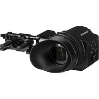
VariCam AU-VCVF20G - Camera PANASONIC - Free user manual and instructions
Find the device manual for free VariCam AU-VCVF20G PANASONIC in PDF.


| Product Type | Cinema Camera |
| Model Number | AU-VCVF20G |
| Brand | Panasonic |
| Sensor | Super 35mm CMOS, 4K |
| Lens Mount | PL Mount |
| Recording Media | P2 cards, microP2 cards |
| Maximum Resolution | 4096 x 2160 |
| Frame Rates | Up to 120 fps in 2K |
| Dynamic Range | 14+ stops (V-Log) |
| Weight | Approx. 3.7 kg (8.2 lbs) |
| Dimensions (W x H x D) | 152 x 209 x 295 mm (6.0 x 8.2 x 11.6 in) |
| Power Supply | DC 12V (AC adapter included) |
| Power Consumption | Approx. 40 W |
| Monitor | 3.2-inch LCD, 720x480 |
| Audio Input | 2 x XLR, 4 channels |
| Video Output | SDI (BNC), HDMI |
| Control | Ethernet, RS-422, USB 2.0 |
| Operating Temperature | 0°C to 40°C (32°F to 104°F) |
| Storage Temperature | -20°C to 60°C (-4°F to 140°F) |
| Repairability | User-replaceable lens mount and fan |
| Cleaning Instructions | Clean sensor with approved swabs; wipe exterior with dry cloth |
| Safety Precautions | Avoid direct sunlight; use specified batteries and power supply |
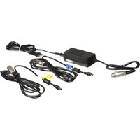
| Accessories Included | AC adapter, power cord, shoulder pad, tripod adapter |
Frequently Asked Questions - VariCam AU-VCVF20G PANASONIC
User questions about VariCam AU-VCVF20G PANASONIC
0 question about this device. Answer the ones you know or ask your own.
Ask a new question about this device
Download the instructions for your Camera in PDF format for free! Find your manual VariCam AU-VCVF20G - PANASONIC and take your electronic device back in hand. On this page are published all the documents necessary for the use of your device. VariCam AU-VCVF20G by PANASONIC.
USER MANUAL VariCam AU-VCVF20G PANASONIC
natural_image
Technical line drawing of a mechanical device with gears and housing (no text or symbols)Before operating this product, please read the instructions carefully and save this manual for future use.
Before using this product, be sure to read "Read this first!" (pages 2 to 5).
Read this first!

indicates safety information.
WARNING:
- To reduce the risk of fire, do not expose this equipment to rain or moisture.
- To reduce the risk of fire, keep this equipment away from all liquids. Use and store only in locations which are not exposed to the risk of dripping or splashing liquids, and do not place any liquid containers on top of the equipment.
WARNING:
Always keep slider unit mounting screws (accessory) out of the reach of babies and small children.
CAUTION:
Do not remove panel covers by unscrewing. No user serviceable parts inside.
Refer servicing to qualified service personnel.
CAUTION:
To reduce the risk of fire and annoying interference, use the recommended accessories only.
CAUTION:
Do not point the eyepiece directly at the sun.
FCC NOTICE (USA)
This device complies with part 15 of the FCC Rules. Operation is subject to the following two conditions:
(1) This device may not cause harmful interference, and (2) this device must accept any interference received, including interference that may cause undesired operation.
CAUTION:
This equipment has been tested and found to comply with the limits for a Class B digital device, pursuant to Part 15 of the FCC Rules. These limits are designed to provide reasonable protection against harmful interference in a residential installation. This equipment generates, uses and can radiate radio frequency energy and, if not installed and used in accordance with the instructions, may cause harmful interference to radio communications. However, there is no guarantee that interference will not occur in a particular installation. If this equipment does cause harmful interference to radio or television reception, which can be determined by turning the equipment off and on, the user is encouraged to try to correct the interference by one or more of the following measures:
- Reorient or relocate the receiving antenna.
- Increase the separation between the equipment and receiver.
- Connect the equipment into an outlet on a circuit different from that to which the receiver is connected.
- Consult the dealer or an experienced radio/TV technician for help.
The user may find the booklet “Something About Interference” available from FCC local regional offices helpful.
FCC Warning:
To assure continued FCC emission limit compliance, follow the attached installation instructions and the user must use only shielded interface cables when connecting to host computer or peripheral devices. Also, any unauthorized changes or modifications to this equipment could void the user's authority to operate this device.
NOTIFICATION (Canada)
CAN ICES-3(B)/NMB-3(B)
For Turky
AEEE Complies with Directive of Turkey.
The rating plate is on the underside of the unit.
Manufactured by: Panasonic Corporation, Osaka, Japan
Importer's name and address of pursuant to EU rules:
Panasonic Marketing Europe GmbH
Panasonic Testing Centre
Winsbergring 15, 22525 Hamburg, Germany
Disposal of Old Equipment
Only for European Union and countries with recycling systems
This symbol on the products, packaging, and/or accompanying documents means that used electrical and electronic products must not be mixed with general household waste.
For proper treatment, recovery and recycling of old products, please take them to applicable collection points in accordance with your national legislation.
By disposing of them correctly, you will help to save valuable resources and prevent any potential negative effects on human health and the environment.
For more information about collection and recycling, please contact your local municipality, dealer or supplier.
Penalties may be applicable for incorrect disposal of this waste, in accordance with national legislation.
- All names, company names, product names, etc., contained in this document are trademarks or registered trademarks of their respective owners.
How to read this document
■Illustrations
- Illustrations may differ from the actual product.
■Conventions used in this manual
- Words and phrases in [ ] brackets indicate details and content displayed in the viewfinder or control panel.
- Words and phrases in < > brackets indicate design text used on this camera, such as button names.
■Reference pages
- Reference pages in this document are indicated by (page 00).
Contents
Read this first!
Before using the camera
Accessories
Description of Parts
Left side
Front
Rear
Top
Adjusting and setting the viewfinder
Adjustment method....
Viewfinder status display
Lamp display
Status display
Storing
Cautions when storing the camera recorder 18
Specifications
19
Before using the camera
- Since the viewfinder uses organic EL, if the same image or letters are allowed to be displayed for a long time, the image may be burned into the screen. There is no problem with the recorded images. Switch the screen by turning off the screen or by using the eye sensor, etc.
Accessories
- DC cable
•BNC cable
-Slider unit
-Slider unit mounting screw (2 pcs.) - Eye cup (already attached to the electronic HD color view finder)
- Eye piece filter (already attached to the electronic HD color view finder)

• After unpacking the product, dispose of the packing material properly.
Description of Parts
Left side
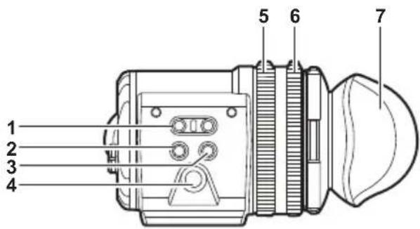
1
User-selected functions can be assigned to each button. Pressing a button performs the assigned function. Functions are set on the viewfinder menu.
2
Displays the camera menu screen.
3
Displays the viewfinder menu screen.
4 Jog dial
Operation dial.
Used for setting, moving, and selecting in menus.
5 Zoom ring
Ring which enlarges/reduces the size of the viewfinder display screen.
This is used to enlarge the display when adjusting the focus. When the display is enlarged, some parts of the video may be hidden.
6 Visibility adjustment ring
Ring which adjusts the visibility. Turn this ring while pressing and holding the upper button.
7 Eye cup
Front

1 Tally LED
Lights up in red during recording or when red tally signals are received. This can be disabled in the viewfinder menu.
2 Video signal input terminal
An input terminal for 3G/HD-SDI video signal input.
Use the supplied BNC cable or the 5C-FB equivalent double-shielded cable for the cable to connect to this terminal.
3 terminal
An input terminal for power supply input.
Connect to the electronic HD color view finder power supply terminal on the camera.
Use the supplied DC cable when connecting a cable to this terminal.
Using the external DC power supply
To use it by itself, connect the
■ External DC power supply
Connect after making sure that the output voltage of the external DC power supply is compatible with the rated voltage of the camera.
When the power of the camera is turned on, inrush current is generated. Insufficient power supply when turning on the power may cause a malfunction. Use of the external DC power supply that can secure power more than twice the total power consumption of the camera is recommended.
- Make sure of the pin alignment of the DC output terminal of the external DC power supply and the camera
Connecting the GND terminal to +12 V power supply by mistake may cause fire or malfunction.
DC IN
| 4○ 1○ |
| 3○ 2○ |
1 GND
2 Data communication (from the viewfinder to the camera body)
3 Data communication (from the camera body to the viewfinder)
4 +12 V
Cable connector
HR10A-7R-4SC (73) (Hirose Electric Co.)
Rear
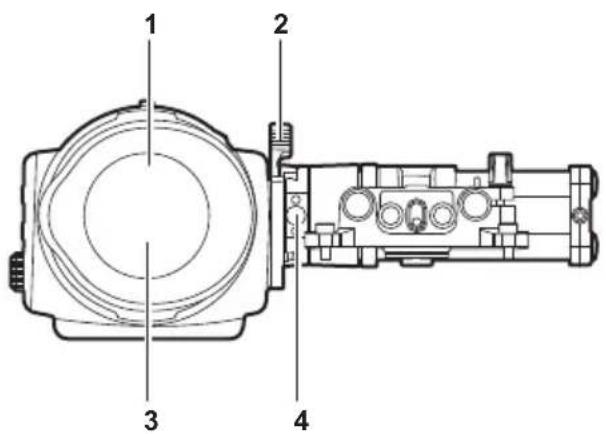
1 Eye sensor
Screen is displayed on the viewfinder when an eye is brought close.
The eye sensor may not work properly depending on the shape of glasses in use, how you hold the camera, or the strong light hitting around the eye piece.
2 Lock lever
Secures the viewfinder in place.
3 Eye piece filter
Protective filter against dust, water, and moisture. Use the camera with this attached.
4 Stopper
Used when removing the viewfinder from the slider unit.
Top

1 Lock lever (left/right position)
Adjusts the position of the viewfinder (left/right).
2 Lock lever (front/back position)
Adjusts the position of the viewfinder (front/back).
Adjusting and setting the viewfinder
The camera's panel is OLED (organic EL).
Positioning your eye near the viewfinder will trigger the eye sensor to automatically display the image.
Adjustment method

a: Lock lever (left/right position)
b: Lock lever (front/back position)
c: Visibility adjustment ring
d: Zoom ring
■Left/right position adjustment
1 Loosen the lock lever (left/right positions).
2 Slide the viewfinder from side to side.
Adjust to a comfortable position.
3 Lock the lock lever (left/right position).
■Front/back position adjustment
1 Loosen the lock lever (front/rear positions).
2 Slide the viewfinder back and forth.
Adjust to a comfortable position.
3 Lock the lock lever (front/back position).
■Visibility adjustment
1 Turn the visibility adjustment ring while pressing holding the upper button.
Visibility adjustment range: -3.6 D - +1.4 D
■Zoom adjustment
1 Adjust by turning the zoom ring.
Adjust to a comfortable view angle while checking the video.
Perform adjustment when adjusting the focus.
Vignetting may occur around the screen of the enlarged image.
Viewfinder status display
In addition to video, the viewfinder displays messages, a center marker, safety zone marker, zebra patterns, and other information that indicate the camera settings and operation status.
Lamp display

flowchart
graph TD
    A["1"] --> B[" "]
    C["2"] --> D[" "]
    E["3"] --> F[" "]
    G["4"] --> H[" "]
1 Green tally lamp
Lights up in green when green tally signals are received.
2 Red tally/recording lamp
Lights up in red during recording or when red tally signals are received.
This will illuminate in red during recording with an external device when [SDI REC REMOTE] is set to [ON], or [SDI RAW] is set to anything other than [OFF].
3 Warning lamp
Flashes or lights up when a warning occurs with the camera.
4 Battery lamp
Starts flashing when the remaining battery level is low. Illuminates when it reaches the battery end.
Status display
Adjusting the screen
1 Press the
Screen adjustment items are displayed on the upper part of the screen.
2 Turn the jog dial button to select the items you want to adjust.
3 Press the jog dial button.
4 Turn the jog dial button to make adjustments.
5 Press the jog dial button.
6 Press the
The screen adjustment items display disappears.
This can also be done in [EVF MENU] → [DISPLAY SETUP].
[EVF MENU] operation
1 Press and hold the button for at least two seconds.
[EVF MENU] is displayed.
[EVF MENU] list
■[DISPLAY SETUP]
| Item Description of settings | |
| [COLOR] Adjusts the color level. | [-32] - [31]•Factory setting: [0] |
| [CONTRAST] Adjusts the contrast. | [-32] - [31]•Factory setting: [0] |
| [BRIGHT] Adjusts the brightness. | [-32] - [31]•Factory setting: [0] |
| [PEAKING] Adjusts the outline of the image in the viewfinder. | [0] - [9]•Factory setting: [0] |
| [R BRT] Adjusts the red color brightness. | [-32] - [31]•Factory setting: [0] |
| [G BRT] Adjusts the green color brightness. | [-32] - [31]•Factory setting: [0] |
| [B BRT] Adjusts the blue color brightness. | [-32] - [31]•Factory setting: [0] |
■[SW MODE]
| Item Description of settings | |
| [FRONT TALLY] Switches enable/disable of the front tally lamp function. [ON]/[OFF] •Factory setting: [ON] | |
| [EYE SENSOR] Sets sensitivity of eye sensor. [NORMAL]: Displays the viewfinder screen according to the eye sensor. [1min]: Keeps the viewfinder screen display for one minute after the eye sensor is released. [5min]: Keeps the viewfinder screen display for five minutes after the eye sensor is released. •Factory setting: [NORMAL] | |
| [B/W] | Switches to monochrome mode. [ON]: Display will be all black and white. [OFF]: Disables the monochrome mode. •Factory setting: [OFF] |
| Item Description of | settings |
| [SCAN] Reverses the display. | [NORMAL]/[REVERSE]•Factory setting: [NORMAL] |
| [PIC. SIZE] Adjusts the image size displayed in the viewfinder.[0] - [3]•Factory setting: [0] | |
| [WFM] (Displays when combined with anything other than the memory card camera-recorder AU-V35LT1G)Sets the display format of the waveform monitor.[Y], [G], [B], [R], [PARADE]•Factory setting: [Y] | |
| [- TRANSPARENCE] (Displays when combined with anything other than the memory card camera-recorder AU-V35LT1G)Sets the transparency of the waveform monitor display.[25%], [50%]•Factory setting: [25%] | |
■ [USER SW 1] (when combined with anything other than the memory card camera-recorder AU-V35LT1G)
The following function is assigned to the
- [EXPAND1]: Switches enable/disable of the enlargement display function.
The setting for enlargement rate is changed by pressing the jog dial.
The setting for position is changed by turning the jog dial.
■ [USER SW 2] (when combined with anything other than the memory card camera-recorder AU-V35LT1G)
The following function is assigned to the
•[WFM]: Switches display/hide of the waveform monitor.
■[INFORMATION]
| Item Description of | settings |
| [OPERATION TIME] Displays the total display time of the organic EL panel of the viewfinder. | |
| [VERSION] Displays the firmware version of the viewfinder. | |
![PANASONIC VariCam AU-VCVF20G - [EVF MENU] list - 1](/content/2026/06/1367953/images/a3d797a24771fce81a4e6c9cdc527003ab82a7cc691e41579717043ccbe0c719.jpg)
- For the function that can be selected when connected to the memory card camera-recorder AU-V35LT1G, visit the Panasonic website (https://pro-av.panasonic.net/manual/en/index.html) and refer to the Operating Guide for VariCam LT (HTML version).
Storing
Cautions when storing the camera recorder
Store each in a location with low humidity and that the temperature is relatively constant.
■Camera body
- Wrap the camera recorder with a soft cloth so that dust does not get into it.
Specifications
Power
DC === 12 V (supplied from the camera body)
4.0 W

indicates safety information.
| Ambient operating temperature 0 °C | -40 °C (32 °F - 104 °F) |
| Ambient operating humidity 10% - 85% (no condensation) | |
| Storage temperature | -20 °C - 60 °C (-4 °F - 140 °F) |
| Weight | Approx. 1.0 kg (2.2 lbs.) |
| Dimensions (W×H×D) | 94.0 mm × 88.0 mm × 111.0 mm(3-23/32 inches × 3-15/32 inches × 4-3/8 inches)(excluding protrusions and accessories) |
| Display panel OLED (organic EL) 0.7 type | |
| Video input method 1080/59.94p, 1080/50p, 1080/60p, 1080/23.98psF, 1080/24psF,1080/25psF, 1080/29.97psF, 1080/59.94i, 1080/50i | |

- Read this first!
- WARNING:
- CAUTION:
- FCC NOTICE (USA)
- FCC Warning:
- NOTIFICATION (Canada)
- For Turky
- Disposal of Old Equipment
- Only for European Union and countries with recycling systems
- How to read this document
- ■Illustrations
- ■Conventions used in this manual
- ■Reference pages
- Contents
- Before using the camera
- Accessories
- Description of Parts
- Left side
- Front
- Video signal input terminal
- terminal
- Using the external DC power supply
- ■ External DC power supply
- Rear
- Eye sensor
- Lock lever
- Eye piece filter
- Stopper
- Top
- Adjusting and setting the viewfinder
- Adjustment method
- ■Zoom adjustment
- Adjust by turning the zoom ring.
- Viewfinder status display
- Lamp display
- Green tally lamp
- Red tally/recording lamp
- Warning lamp
- Battery lamp
- Status display
- Adjusting the screen
- [EVF MENU] operation
- Press and hold the button for at least two seconds.
- [EVF MENU] list
- Storing
- Cautions when storing the camera recorder
- ■Camera body
- Specifications
Brand : PANASONIC
Model : VariCam AU-VCVF20G
Category : Camera