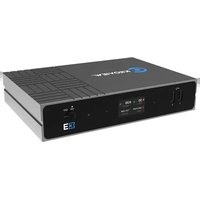
E3 - Server Kiloview - Free user manual and instructions
Find the device manual for free E3 Kiloview in PDF.


| Brand | Kiloview |
| Model | E3 |
| Product Type | Video Streaming Server |
| Video Input | HDMI, SDI |
| Video Output | HDMI, SDI, IP |
| Max Video Resolution | 3840x2160p60 |
| Encoding Formats | H.264, H.265 |
| Streaming Protocols | RTMP, RTSP, SRT, HLS |
| Network Interface | Gigabit Ethernet (RJ45) |
| Audio Support | Embedded HDMI/SDI, 3.5mm jack |
| Control | Web UI, Front Panel Buttons |
| Power Input | 12V DC, 2A |
| Power Consumption | Max 15W |
| Dimensions (W x D x H) | 200 x 150 x 44 mm |
| Weight | 1.5 kg |
| Operating Temperature | 0°C to 45°C |
| Storage Temperature | -20°C to 60°C |
| Humidity | 10% to 90% (non-condensing) |
| Chassis Material | Aluminum alloy |
| Cooling | Passive (fanless) |
| Mounting | Desktop, optional rack mount |
| Accessories Included | Power adapter, HDMI cable, quick start guide |
| Warranty | 1 year limited |
Frequently Asked Questions - E3 Kiloview
User questions about E3 Kiloview
0 question about this device. Answer the ones you know or ask your own.
Ask a new question about this device
Download the instructions for your Server in PDF format for free! Find your manual E3 - Kiloview and take your electronic device back in hand. On this page are published all the documents necessary for the use of your device. E3 by Kiloview.
USER MANUAL E3 Kiloview
E3 4K HDMI/3G-SDI H.265 Video Encoder
User Manual
KILOVIEW ELECTRONICS CO.,LTD
Legal Statement
Subject to the receiving of this document from Changsha Kiloview Electronics Co., Ltd., (Hereina referred to “Kiloview”), the following terms are understood and agreed. Or else, please stop using this document.
This document is copyright of Kiloview, all rights reserved. The document covers the proprietary information of the company. No company or individual may copy, transmit, distribute, use or dis the document and any images, forms, data and other information contained in the document with the prior written permission of the company.
C is the registered trademark of Kiloview. The name and logo are the trademarks or registered trademarks of the company. Other products or company names mentioned in this document may the trademarks or registered trademarks of their respective owners. The reading of this document without the prior written consent of the company or the third-party rights holder does not imply the reader is given any right to use any of the marks appearing in this document by implicati evidence or otherwise.
This product complies with the design requirements related to environmental protection and person safety. The storage, usage and disposal of the product shall be in accordance with the product relevant contract or relevant national laws and regulations.
This document is provided "as is" and "only in this state". Products and technical updates are subject to change without prior notice.
For matters not covered in this document, please visit our website www.kiloview.com for informa and technical support.
Contents
1 Product Introduction....1
1.1 Advantages.... 1
2 Parameters....4
3 Packing List and Device Interface 5
3.1 Packing List 5
3.2 Device Interface 5
3.3 Device Indicators 5
4 Installation and Connection....6
4.1 Video Signal Connection....6
4.2 Network Connection....6
4.3 Power Connection 7
5 Display Screen and Touch Buttons....8
5.1 Use of Touch Buttons....8
5.2 Use of Display Screen 9
5.2.1 Status of Device 9
5.2.2 HDMI Video Source Information 10
5.2.3 SDI Video Source Information 10
5.2.4 Network Status Information....10
6 Login and Network Configuration....11
6.1 Device Login....11
6.2 Network Configuration....11
6.2.1 Ethernet....11
6.2.2 Advanced Settings 12
7 Parameter Configuration....14
7.1 Encoding Mode Selection....14
7.2 Information Bar 15
7.3 Video Encoding Parameter 17
7.4 Audio Encoding Settings....19
7.4.1 Audio Signal Source Settings.... 19
7.4.2 Audio Encoding Parameter Settings 20
7.5 Image and OSD Overlay 22
7.5.1 Image Overlay 22
7.5.2 OSD Overlay....23
7.6 Recording 25
8 Streaming Service 26
8.1 NDI|HX....27
8.2 NDI Discovery Server 28
8.3 RTSP 30
8.4 RTMP Streaming (Live Streaming) 31
8.5 SRT 37
8.6 HLS Streaming....38
8.7 TS-UDP Streaming (Unicast and Multicast) 39
9 User Management....40
10 Area and Time Management....41
11 System Settings....42
11.1 Language....42
11.2 Restore 42
11.3 Reboot 43
11.4 Firmware Upgrade 43
11.4.1 Web Page for Upgrade....44
11.4.2 Recovery 44
12 Others 46
1 Product Introduction
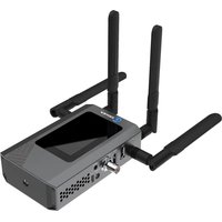
E3 is a new generation of 4K UHD H.265 video encoder. It supports 3G-SDI, HDMI dual interface input/loop output, resolution up to 4KP30, supports all mainstream protocols such as NDI/SRT/RTMP, etc and can realize multi-protocol and multi-platform streaming to 16 live broadcast platforms at the same time. It is a cost-effective equipment with "multiple streams" and "multiple functions" all in one.

1.1 Advantages
● Comprehensive functions, superior performance, all in one
◆ HDMI+SDI dual-interface input, both interfaces support loop through, which can help you adapt to image acquisition devices with different interfaces. HDMI 1.4b standard and UHD video input up to 3840×2160p 30Hz. SDI conforms to SMPTE 424M(3G-SDI) standard, compatible with SMPTE 292M (HD-SDI) and SMPTE 259M (SD-SDI), allowing SDI video signal input up to 1920×1080p 60Hz.
◆ 4K UHD resolution (HDMI) supported, with optional H.264(AVC) and H.265(HEVC) encoding. H.264(AVC) supports Baseline/Main/High profile, up to Level 5.1. H.265(HEVC) supports Main profile, up to Level 5.0.
◆ High-quality video interlaced format(interlaced) to progressive format (progressive) capability, it can convert 480i/576i/1080i format to high-quality, smooth progressive video and output after encoding.
Under the condition of 1920×1080 and below resolution, it supports dual-channel video encoding and output IP video stream at the same time.
It can also choose one encoding or picture-in-picture (MIX) encoding in dual video input.
◆ HDMI and SDI multi-channel audio embedded, channel selection and exchange/mapping: HDMI supports up to 4 channels/SDI supports up to 8-channel audio embedded, channel selection, channel exchange and mapping functions. Support audio input from the Line-in analog audio interface.
◆ Supports multiple audio encoding formats such as AAC/MPEG-4/MPEG-3/MPEG-2/Opus/G.711, etc and can encode up to 4 different audio formats at the same time to meet the streaming requirements of different media protocols.
◆ Support Logo/picture/text overlay function, support video rotation/cropping, mirroring, color adjustment and other advanced capabilities.
◆ Support NDI|HX, which can integrate into the NDI system more efficiently.
◆ Many IP streaming protocols supported: SRT, RTMP/RTMPS (push), HLS (service or push), TS over UDP, RTP/RTSP, WebRTC, Onvif and more protocols can be extended in the future.
◆ Support up to 8 streams of different IP protocols or different destinations of the same protocol, realizing "one device with multiple streams" and "one device with multiple functions". E3 realizes the function superposition of Kiloview's previous successful products E1 and E2. Only one device can have the functions of two products; in addition, it also has 4K UHD video processing capabilities, H.264 AVC/H.265 HEVC support capabilities and more powerful performance, with unparalleled cost-effective advantages.
● Professional and rich business functions for broadcast
production and Pro AV applications
It surpasses the same-level H.264/H.265 video coding quality and excellent color quality, and can still maintain excellent image decoding and restoration quality under low bit rate/ultra-low bit rate conditions, and the video is
smooth without frame loss.
◆ Expandable local recording function based on USB: the input video can be recorded on the local USB disk into a professional .mov/.mp4 video file format, the recorded file has precise synchronous time code, and post-editing can be based on the time of the recorded file code to achieve inter-frame alignment.
◆ Support NFS/CIFS/SMB/FTP and other NAS protocols to realize video recording function based on network storage.
Tally indication based on high-brightness LCD screen: NDI tally control capability is supported by default, tally status is displayed with high brightness on the large-size LCD screen on the front panel; other tally control functions can be supported through API or software function expansion.
It seamlessly connects with TriCaster/vMix/OBS/Kiloview Multiview/NDI Studio Monitor and other professional video monitoring and production software based on NDI; combined with free NDI Virtual Input software, it can also realize the function of network virtual camera/video capture card.
◆ Through USB to RS-232/RS-485/RS-422, NDI/Onvif and other remote camera PTZ control and iris, focus and white balance adjustment functions can be realized.
◆ After connecting to the USB headset, it can work with Kiloview Intercom Server (KIS), so as to realize the functions of IP voice call and voice command and dispatch.
2 Parameters
| Model | E3 |
| Input Interface | 1*3G-SDI1*HDMI 1.4b |
| Output Interface | 1*3G-SDI (LOOP OUT)1*HDMI 1.4b (LOOP OUT) |
| Audio Interface | 8 channel of SDI embedded audio4 channel of HDMI embedded audio1*3.5mm Line in audio interface |
| USB Interface | 2*USB 2.0 Type-C1*USB 2.0 Type-A |
| Network Interface | 1*10M/100M/1000M RJ45 Ethernet PortPoE supported (802.3af class 3) |
| Transmission | Gigabit wired network |
| Streaming Protocols | NDI|HX2/NDI|HX3/SRT/RTMP/ RTMPS/HLS/TS over UDP/RTP/RTSP Onvif(Extensible for SIP/GB-T2818) |
| Video Resolution | HDMI support input and loop out3840x2160p30fps/1920x1080p60fps/1920x1080i50/59.94/60fpsSDI support input and loop out:1920x1080p60fps/1920x1080i50/ 59.94/60fps/1280x720p25/29.97/30/50/59.94/60fps |
| Video Resolution Input | Up to 4Kp30(HDMI) |
| Video Encoding | H.265(HEVC)/ H.264(AVC) |
| Encoding Resolution | Up to 4KP30 |
| Management | Web UI/ Remote management with KILOVIEW KiloLink Ser |
| Power Supply | DC 12V/1A |
| Power Consumption | 6w |
| Working Temperature | -20°C~45°C |
3 Packing List and Device Interface
3.1 Packing List
| Name | Quantity |
| E3 Encoder | 1 |
| DC 12V power supply | 1 |
| Warranty card | 1 |
| Cold shoe | 1 |
| Quick Start Guide | 1 |
3.2 Device Interface

| 1. Power supply Interface | 2. 3.5mm LINE IN | 3. USB TYPE-A | 4. SDI Loop |
| 5. SDI Input | 6. HDMI Loop | 7. HDMI Input | 8. 1000M Ethernet (POE) |
| 9. USB TYPE-C | 10. USB TYPE-C | 11. LCD screen and Touch button | 12. Power Switch |
3.3 Device Indicators
| LCD Screen | Status |
| Green Color | PVW | |||
| Red Color | PGM | |||
| LED Indicators | Name | Color | Status | Description |
| Power | White | ON | Power connected | |
| Off | Power off or failure | |||
4 Installation and Connection
4.1 Video Signal Connection
Connect HDMI signal from a source (such as camera) to the device HDMI port through a cable.

natural_image
Diagram of electronic device rear panel with labeled ports and connectors (no text or symbols)4.2 Network Connection
Connect the network cable to Ethernet port, and connect the other end to the network switch or directly to the network port of the computer.

natural_image
Diagram of electronic device rear panel with labeled ports and connectors (no text or symbols)4.3 Power Connection
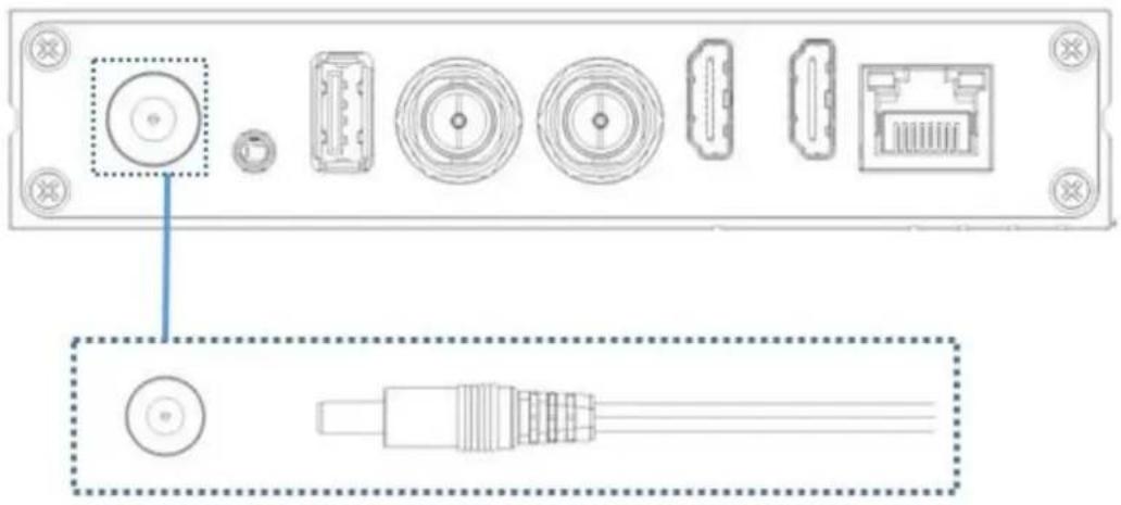
Plug in the power adapter and turn on the power switch, the light will be on. Then the device starts working, it will take 30\~40s.
natural_image
Diagram of an electronic device rear panel with labeled ports and connectors (no text or symbols present)
Note: If your switcher supports POE, there is no need to connect the power supply.
5 Display Screen and Touch Buttons
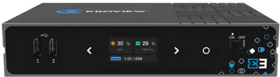
The E3 is equipped with a color LCD screen and touch buttons on the front panel. With the built-in screen, you can easily check the device status, input source and network, etc. The LCD screen is also a big-sized Tally to display the preview/program status.
5.1 Use of Touch Buttons
The touch button can switch the display module, enter the current display module, check the working mode, view the current status and restart the device and so on.
Touch it to go to the previous page.
Touch it to next page.
Touch it to confirm.
5.2 Use of Display Screen
5.2.1 Status of Device
The first page of the LCD display shows: the current working status, CPU usage, memory usage and the current version of the device.
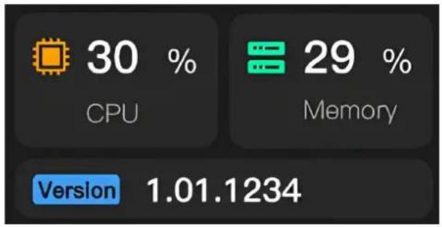
CPU: Indicates the CPU usage.
Memory: Indicates memory usage.
Version: Indicates the firmware version currently running on the device.
Touch the OK button on this page to enter the internal settings of the module. In this interface, you can choose to quickly reset, reboot and restore the factory settings. Select BACK and touch the OK button to exit the current page.
Screen Protector: Indicates the device screen saver time.
Restore Factory: Indicates restoring to factory settings.
Reboot: Indicates device restart.
Keyboard Clicks: Indicates a device keyboard click.


5.2.2 HDMI Video Source Information
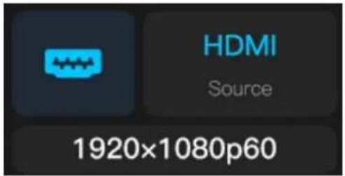
The second page of the LCD display shows: the current HDMI video input source and parameters of the device.
When the HDMI video input source is connected, the system will automatically identify and display the parameter information of the video source such as the resolution, and display Disconnected when there is no video input source.
5.2.3 SDI Video Source Information
The third page of the LCD display shows: the current SDI video input source and parameters of the device.
When the SDI video input source is connected, the system will automatically identify and display the parameter information of the video source, and display Disconnected when there is no video input source.

5.2.4 Network Status Information
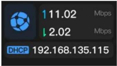
The fourth page of the LCD display shows: the current network status of the device.
The up and down arrows indicate the real-time network uplink and downlink rates.
DHCP: Indicates the dynamic IP address obtained by the device.
STATIC: Indicates the static IP address obtained by the device.
6 Login and Network Configuration
6.1 Device Login
1. Network Settings for your PC
Connect the computer to the network where the E3 is located, and check that the network communication between the E3 and the computer is reachable. Users can use the CMD tool that comes with the window to test.
2. WEB management page login
Open the browser on the computer, enter the IP address obtained by E3 in the browser URL, and enter the username and password in the login dialog box.
Both default username and password are admin.

Note: Due to the browser compatibility issues, it may cause the web page display abnormal, it
is recommended to use Chrome or Edge.
6.2 Network Configuration
6.2.1 Ethernet
After login, you could configure internet IP by DHCP or manually (Default is DHCP). This IP address could be used for network streaming and device management. Once IP address configured, you could directly visit this IP address to login to the device.
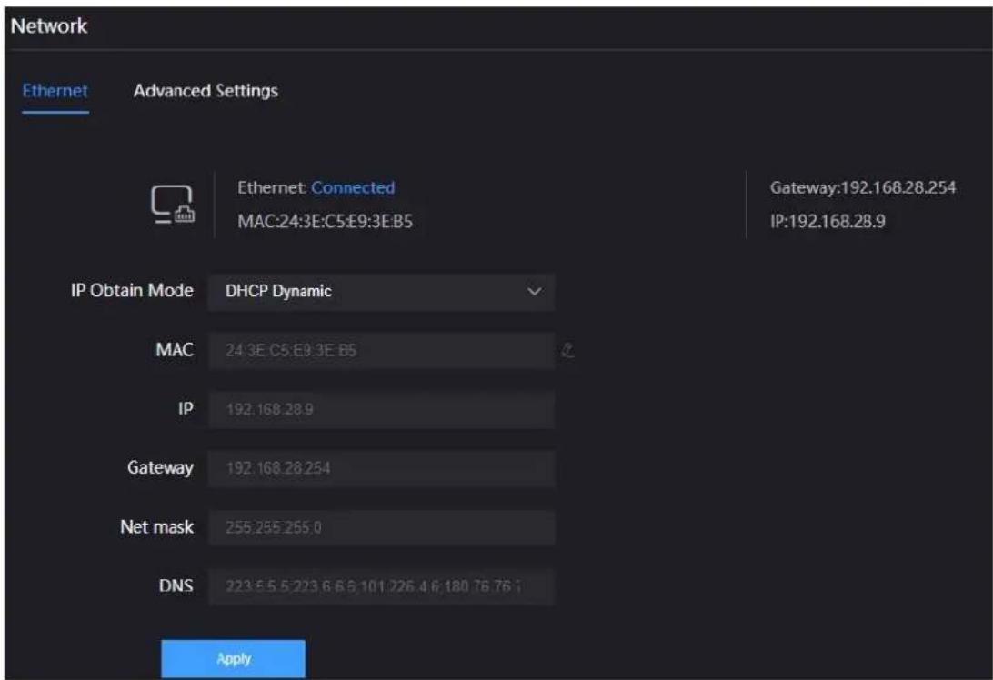
There are two ways to get the address, one is DHCP, and the other is manual. To use DHCP, please ensure that the router or switch has enabled the DHCP service. This method is simple and convenient, but the IP obtained by DHCP changes continuously, and you cannot directly know what IP address the encoder gets.
To select manual IP address obtaining, you need to enter a fixed IP to the device, and this IP address is fixed as long as the device does not restore the factory settings, which is relatively stable. The automatic allocation is to automatically allocate an IP address according to the MAC address of the device. If the device needs to share the network with other devices, this method can avoid the problem of IP address conflicts, but the IP address allocation strategy needs to be maintained regularly. Manual assignment and automatic allocation both have their own advantages and disadvantages, depending on the specific requirements. Therefore, the choice between manual assignment and automatic allocation can be made based on the actual needs.
6.2.2 Advanced Settings
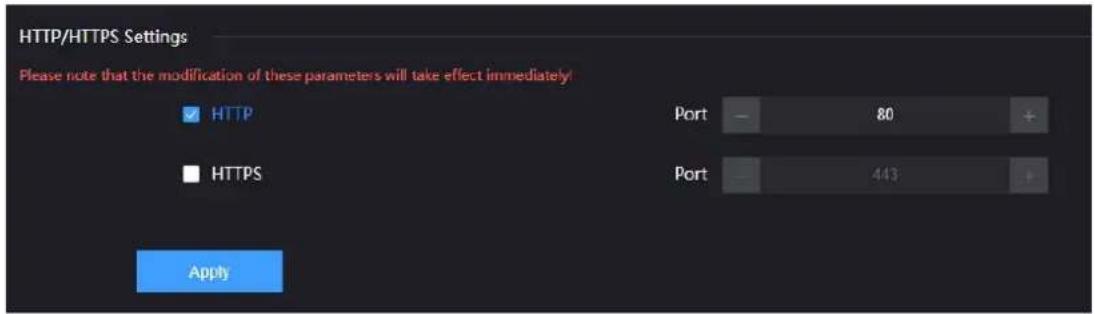
- HTTP/HTTP Setting
The default web service port is 80 (https port is 443). You can change it (range: 1-65535) accordingly. After revising the port, visit device configuration page. You need to add the changed port behind the device IP address before you visit. For example, the device normal login IP address is 192.168.1.168, change Web service port from 80 to 90, HTTPS service port from 443 to 450, then enter 192.168.1.168:90 or https://192.168.1.168:450 to visit device respectively.
By HTTPS, if the web browser prompts certificate errors which is caused by the browser certificate security authentication, you will need to add it to the safe list of the browser.
- Routing Strategy
The routing strategy is for routing release and reception. Its operation object is data package. According to the needs, the data packet transmission path can be changed according to a certain strategy. When the device is connected to multiple network links, the different data link can be sent according to the appointed network link through designated strategy, which improves the utilization efficiency of the link.

Note: It is required that professional person with knowledge of the current network routing
table or network to operate routing strategy. Incorrect configuration may cause device abnormal.
7 Parameter Configuration
7.1 Encoding Mode Selection
E3 supports 3G-SDI, HDMI dual interface input/loop out. Users can choose the HDMI or/and SDI interfaces as the video input source, and can dynamically switch the input source. Users can also choose to synthesize the video input of HDMI and SDI and then encode the output. Modify the encoding parameters of the device by clicking the HDMI, SDI, and Mix switches on the page.
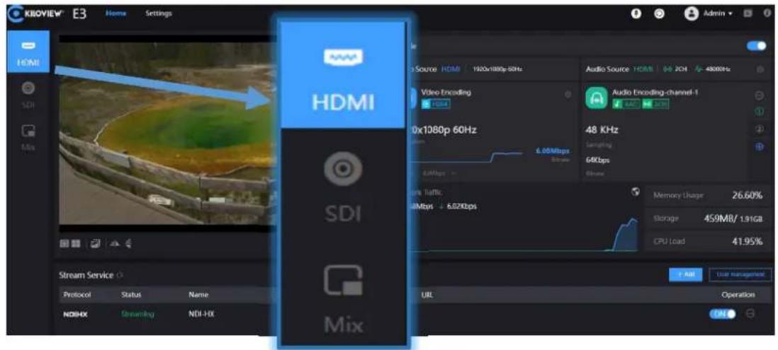
- Mix (mix coding) settings
Click the Mix encoding mode on the left side of the home page, and then click the encoding switch button on the right, a dialog box will pop up to prompt that this operation will exit the HDMI/SDI encoding mode and switch to the mixed encoding mode that supports picture-in-picture, click OK.
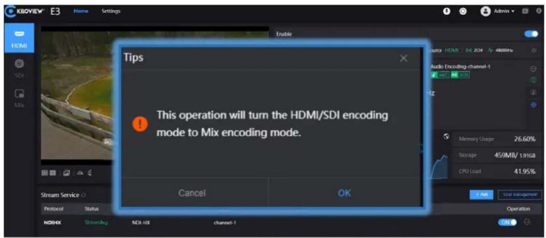
- Mix(mix coding) layout settings
Click on the button in the information bar, users can switch the video sources of the main and sub video and set the layout. The layout setting only sets the sub video parameters, and each parameter has 7 preset parameter icons for selection. The parameter settings are as follows:
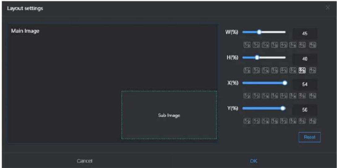
● W (%) : Modify the width of the secondary video.
● H (%) : Modify the height of the secondary video.
● X (%) : Modify the X axis of the secondary video.
- Y (%): Modify the Y axis of the secondary video.
- : Reset all parameters of the secondary video.
7.2 Information Bar
In the information bar of the HOME page, the left window is the preview window of the input video source, which supports picture/video preview. When the user previews the video using the picture mode, the picture stream is displayed, which shows a change of a picture in about three seconds. Using the video preview, the picture is a smooth video. The switch between picture mode and video mode can be controlled by the button in the lower right corner of the preview window.
☑ is picture mode ☑ is video mode. After selecting the preview mode, you need to click the video status next to the preview mode, select Refresh Preview, and the preview window will switch to the selected preview mode.
If the preview window is displayed in black, it means that the device has not detected the video input source, and you need to check whether the input cable is correct.
☐ : Enable safety frame for the video.
: Enable centerline for preview
: Flip the video horizontally (Mirror).
4 : Flip the video vertically (Flip).

The right window displays the video and audio encoding parameter information, click the encoding button to open/close encoding.
The switching of HDMI encoding, SDI encoding and Mix encoding pages can be completed by clicking the upper left corner of the window. The following is a brief introduction to the relevant encoding parameters and interfaces:
- Video Encoding: Displays the resolution and real-time frame rate of the input video source.
● Video Source: Displays the connector of the input signal source.
● Encoding Format: Displays the encoding method of the signal source.
● Resolution: Displays the encoding resolution of the source.
● Bit rate: Displays the encoded frame rate of the source.
● Audio Sources: Displays the interface, channel and sampling rate of the input audio source.
● Audio Format: Displays the encoded audio format of the source.
● Audio Sampling: Displays the encoded audio sample rate of the source.
● Audio Channels: Displays the encoded audio channels of the source.
● Network Traffic: Displays the real-time uplink and downlink network speeds of the current device.
● Memory Usage: Display device memory status.
● Storage: Displays the storage space of the device.
● CPU Load: Displays the CPU load of the device.
7.3 Video Encoding Parameter
Click the setting button in the upper right corner of the video encoding on the information bar page to modify the video encoding parameters, and click the bit rate on the video interface to modify the video bit rate in any time.

The video encoding parameters are as shown as below:
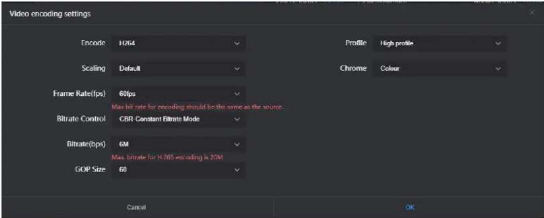
- There are two encoding formats, you can choose H.264 or H.265 according to your needs.
- There are 7 options for "Scaling". The default setting is the default size, which means, after encoding, the resolution remains the same as the input video resolution. You can also upscale or downscale the resolution after encoding.
- "Frame Rate(fps)" supports adjustment between 24FPS-60FPS, and you can also customize the bitrate size. Customization is to manually specify the frame rate after video encoding. Theoretically, it cannot be set higher than the original frame rate of the video.
- There are two types of "Bitrate Control": CBR and VBR. CBR means constant bitrate mode and VBR means dynamic bitrate mode. CBR is a stable bit rate, and VBR is constantly changing bit rate according to the actual content. Generally, CBR is used for network transmission to ensure the transmission quality, and VBR is used for file storage to ensure the quality of video files. The default setting is CBR;
- "GOP Size (I-frame interval)" has 7 options and supports custom selection. The GOP (Group of Pictures) strategy affects the encoding quality. GOP means group of pictures, and a GOP is a group of continuous pictures. This can be adjusted according to the actual situation, the default is 60, this value can also meet most of the needs.
- "Profile" supports three levels: Baseline, Main profile and High profile. This should be set according to the encoding level supported by the platform. High profile has the highest compression efficiency, that is, the image quality is the best under the same bitrate, and baseline is the most widely supported. The default setting is high profile, which should be set according to the actual platform support.
- "Chrome" has two options: Gray and Color. Gray is black and white, while Color is to keep the original color. The default setting is color.
7.4 Audio Encoding Settings
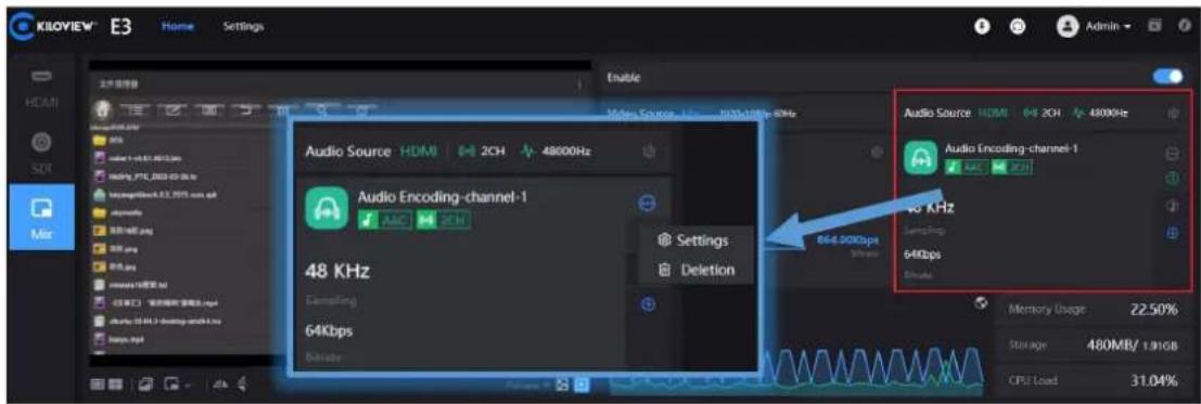
Click the setting button in the information bar to enter the audio and video encoding setting interface, the user can configure the audio source and audio encoding parameters, and click quickly add an audio preset template.
7.4.1 Audio Signal Source Settings
There are three audio signal source modes for audio input: HDMI, SDI input and analog input (LINE IN). The default audio signal source is HDMI.

7.4.2 Audio Encoding Parameter Settings
Click the settings button in the information bar to enter the audio and video encoding setting interface.

There are two audio encoding modes optional: AAC and G.711. The audio sampling rate can be selected according to actual needs. There are two ways of audio channels: stereo and mono. The encoding bit rate can be adjusted within the range of 16K-512K, and the default is 64Kbps.


Note: After modifying the audio resampling policy or sampling rate, the user needs to perform a "quick reset" or "device restart" to make it work.
7.5 Image and OSD Overlay
7.5.1 Image Overlay
- Click the "button" button in the information bar, select picture management, and click "Add Images".
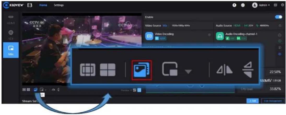

- In the “add images” box, fill in the name, choose to upload a picture, and then save it. After the picture is uploaded successfully, it will be displayed in the picture list. The image format must be JPG/JPEG/PNG, and the size should not exceed 5M.

- Click "Image Management" again to return to the image overlay interface, and click "Add Material".

- Enter the setting interface, select picture for overlay type, then select the picture to be added and the overlay position, and click "OK".

- The configured overlay image will appear in the status bar, check the overlay image, and finally check the overlay to make it work.


Note: Due to the limited storage space, there is a limit on uploading pictures, up to 10 pictures can be uploaded, and the maximum size of a single picture is 5M. The pixels of the overlay Logo image should not be too large, otherwise too much video will be covered. The picture format supports JPG, JPEG and PNG. The effect of overlaying image can not be seen in the preview window, and it can only be displayed by software decoding or decoder on the computer side and outputting to the monitor.
7.5.2 OSD Overlay
Information bar "OSD" - "Overlay" - "Add Material".

Enter the configuration page, select the overlay type such as "Text" and "Time And Date".

Overlay Type: "Text, Date, Time, Date/Time and Image" can be selected.
Overlay Position: 7 preset display positions and custom positions can be selected, and the display position can be selected according to actual needs.
Text Size: There are three automatic sizes of "Auto-Large, Auto-Medium and Auto-Small" to choose, and can also be adjusted between 9px-96px.
Text Style: Normal and Bold.
Text Border: Border ranges from 0 to 10px.
Text Color: The user can choose the text color.
Border Color: The user can choose the Border color.
7.6 Recording
E3 supports both local and NAS video recording.
Take local video recording as an example, the specific operations are as follows:
- Insert the USB memory into E3.
- Start recording on E3.
- For video Settings, open "Settings" in the WEB page and click recording management. Users can see the display and setting of video parameters in the column of video management.
![Main Stream Sub Stream [ REC ] Video Source HDMI 1920x1080@59.9Hz Audio Source HDMI 2CH 48000Hz Video Encoding 1920x1080@59Hz Audio Encoding-Channel-1 48000 Hz Sampling 64Kbps Network Traffic 165.25Kbps ↓ 25.00Kbps Use Memory 19.15% Storage 218MB/ 251MB CPU Load 30.96%](/content/2026/06/1366286/images/b7de270aa2ebc5d5e6d0eca9fe6eb3787dd0fc64bcbee42ce125306a55c92c56.jpg)
- By clicking "Stop recording", the user can check the "Recording status" in the recording, check the utilization rate of the memory, or download the video files that have been stored in the memory to the computer.


Note:
When the user unplugs the memory during the recording process, if the format of .avi/.mp4 is used, the video file may be permanently damaged and cannot be played. Using the video file in TS format can avoid this problem well. At the same TS format is also supported by most mainstream video players.
If non-TS format is used for recording, when the recording is completed, please the recording manually, and then remove the storage device to ensure that the recording can be played normally.
8 Streaming Service
E3 currently support most of the streaming protocols: NDI | HX2 / NDI | HX3 / SRT/RTMP/RTMPS/HLS/TS over UDP/RTP, RTSP/Onvif, etc. One stream of the E3 encoder can be pushed up to 8 different streaming services at the same time. By using HDMI and SDI encoding, it can be pushed simultaneously up to 16 different live-streaming platforms.
8.1 NDI|HX
The E3 encoder currently supports NDI|HX2/NDI|HX3, and the stream service is set as "on" by default. Click the [on] switch to turn on or off the NDI|HX stream service.

Click the Settings button behind the streaming service to enter the streaming parameter configuration page.

Name: The name can be customized, and Chinese, English and numeric characters are supported.
Audio: Audio channel source can be selected.
Group: Group names can contain English letters and numbers. Multiple group names are allowed to be configured, and the group names are separated by English commas. The default group is the public group. If the user does not want other devices on the network to be able to search for it, the user can set a specified group name, and other devices need to use the specified group name to search for this device.
Channel Name: When there are multiple NDI sources on the same network, the channel names of the devices can be modified to identify different devices.
Connection: There are two connection modes: UNICAST and MULTICAST, and UNICAST is used for transmission by default. UNICAST is a one-to-one communication mode between devices, and multicast is a device-to-group communication mode, that is, devices that join the same group can receive all data sent by the device.
Server Address: Register the discovery of the source with the discovery server. See the Discovery Server section for details.
After the configuration is completed, the user can find and output the NDI source via NDI-based software, and distinguish different NDI sources by the device name and channel name.

8.2 NDI Discovery Server
The NDI discovery server can replace NDI automatic discovery with a server, all NDI sources are registered to the server, and the receiving end obtains the NDI source from the server. Users can also configure this function to send the output video stream to the receiving end across network segments.
Use a computer (server) to log in to the NEWTEK official website (https://ndi.tv/sdk/) to download and install the NDI SDK. After installation, run Bin\Utilities\x64\NDI Discovery Service.exe in the installation directory.
![DXProgram Files\NewTek\NDI 4 SDK\Bin\UtilBesud64\NewTek NDI Discovery Service.exe NDI Discovery Service v1.00 (c)2019 NewTek, int. 0:00:01 [----] 0 Sources, 0 Listeners.](/content/2026/06/1366286/images/584f63e9a03e7808b8a107c4f9bab86418c6f7cd5401ce620ef10e7adaee7545.jpg)
The NDI encoder configures the receiving end IP address in the discovery server, and NDI will register to the server. It is recommended that the receiving end address be configured as a static IP address to prevent NDI connection loss caused by IP reassignment.
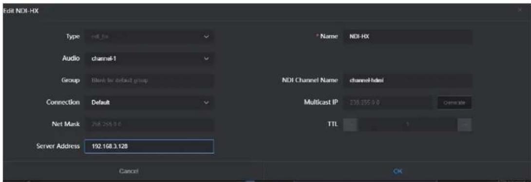
Click "Discovery Server" on the configuration page of the decoder, open the function, and set the discovery server address as the IP address of the computer (The one that open discovery server function). After saving the configuration, the receiving end can discover the NDI streams registered to the server.


Note: After enabling this function, the mDNS automatic discovery function is invalid. The video stream output by the encoder can only be sent to the specified server, and the receiver must register with the same discovery server to pull the NDI stream.
8.3 RTSP
The encoder can add one RTSP stream by default. As long as the RTSP stream is not being pulled and decoded, there will be no additional load on the encoder. As shown in the figure below, if the IP address of the encoder is 192.168.43.228, and the set service port is 554, then the stream address of the RTSP service is
rtsp://192.168.43.228:554/ch01.


Under the same LAN, the computer can pull the RTSP stream through VLC, test whether the encoding is normal and view parameter information. After installing and opening VLC, select "Network", then "Enter Network URL", you will enter an interface for entering the network URL, fill in the URL address of the encoder's RTSP service, and you can start playing.


Note: The URL cannot contain Chinese, the content needs to be copied completely, and the punctuation marks must not be missing.
8.4 RTMP Streaming (Live Streaming)
When using RTMP streaming, the user must first determine the platform that supports RTMP service, and the platform must be able to provide the RTMP stream address, otherwise the encoder cannot make the streaming.

Note: The principle of RTMP streaming is that it must be pushed from the encoder to the platform, and the computer/decoder then pulls the RTMP stream from the platform for playing. The encoder cannot directly push the RTMP stream to the computer/decoder for playing.
1) Push the stream to YouTube live broadcast platform.
First, register an account on the YouTube platform, log in to the YouTube webpage, click the Create button in the upper right corner of the webpage, select Go live, and the system will automatically jump to the Live Streaming setup page.
![YouTube Search Home Python Electrical Engineering Music Debubbles Gaming Camera Live Tablet computers Editing Background music Live xamps Manga Matures Sick by Unread videos (+) Go Live Share One:有CPBbanking,5分接手问题! What is Kikovise Factory Info? How is a circuit board... Kikovise Electronics 253 views > 2 years ago Learn Se Programming - Golang Tutorial for Beginners NewCodeCamp.org 8.0M views > 4 years ago 异形系列1 [普罗米纳斯]解读 删减37分钟超秘密 易布系列是10颗,四万手解读《音 罗米纳斯》。完成37分钟超秘密... 大视频电影 1.4M views > 5 years ago NOI EXPLAINED! Add network Input to ATEM MINI & OBS wilt... Ask PdRill 77K views > 2 years ago Explore Teaching Music Works Live Saming Sports Fashion & Beauty More from YouTube YouTube Premium YouTube Studio YouTube Music WordPress Tutorial For Beginners Build a COMPLETE React Admin Dashboard App | React, Materials... Build a COMPLETE React Admin Dashboard App | React, Materials... Relaxing Music to Relieve Stress, Anxiety & Depression Mind... Live Youself! 4.5M views - Streamed 11 episodes ago PyTorch for Beginners PyTorch for Deep Learning & Machine Learning - Full Course NewCodeCamp.org 762K views > 10 months ago MSFS2020 LIVE ESMQ - EFKI Kalimar Airport, Sweden - Kapla... Windows Production MHR views > Documented 9 months ago](/content/2026/06/1366286/images/8eccbcb8c7b2d255a08736ffeb978fa899f7ab7f2690d84a7787bdedd3646283.jpg)
The first time you enable live streaming, you may need to wait 24 hours. Once enabled, you can go live immediately.


Note: There are two streaming codes that come out, and they must be combined to form a complete RTMP streaming address. The format is rtmp address/live code, and a "/" must be added after the rtmp address, and then the live code. There cannot be spaces in the address. The live broadcast code of the YouTube platform is constantly changing, so the next time you push the stream, you need to fill in the address again.
Click Select Stream Key and select Create New Stream Key, in the pop-up dialog box.
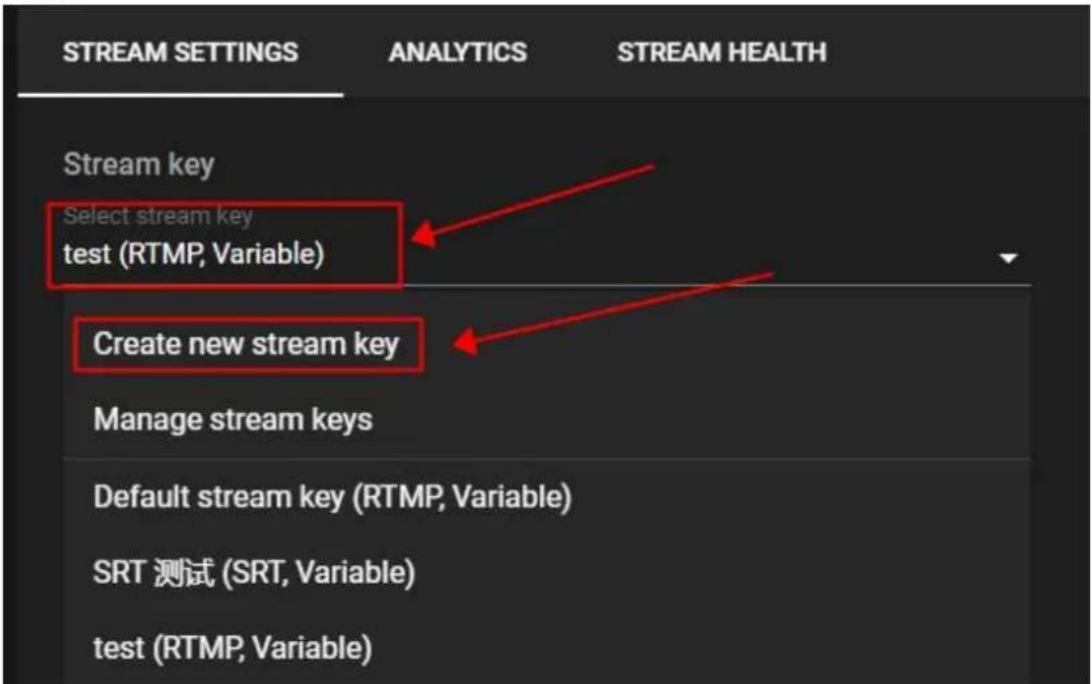
Enter a name and select RTMP for the streaming protoc YouTube automatically detects a stream's resolution and frame rate. Turn on manual settings to select your own.
Create new stream key
Name (required)
Add a name
Description
Add a description (optional)
Streaming protocol
Select how you want to transfer the video stream between your encoder and YouTube. RTMP is the default and works for most cases.
RTMP (Default)

Stream resolution
YouTube automatically detects a stream's resolution and frame rate. Turn on manual settings to select your own.

Turn on manual settings
Resolution

Select the streaming key we just created

After setting up on YouTube platform, you need to set up push stream on encoder side. Connect the encoder network and login to the encoder's management interface-streaming service, click "Add" button to add a streaming service, in the pop-up setting window type select RTMP, fill in the push streaming address on YouTube to the push address (the format of RTMP address is: rtmp address/live code), and then click "OK" on it. If the push stream is not successful, please check the encoder network.



Note: If the platform requires RTMPS streaming, the encoder also supports it. Enter the RTMP push parameter setting, write the URL in RTMPS format in the "push point"
2) RTMP Streaming to other platforms
If you need to push to other RTMP platforms, you must first obtain an RTMP stream
address, otherwise you cannot make the streaming. If you have any questions about obtaining the streaming address, you can contact the technical support of the live broadcast platform for help.

Note: Most of the live broadcast platforms only provide streaming URLs. You can push the video stream to the live broadcast platform through the encoder and watch it online through the platform website or by scanning the QR code on your mobile phone. If you need to pull the video stream of the live broadcast platform to the local, the platform needs to be able to provide the pull stream address, which can only be supported by some specific platforms.
8.5 SRT
- Click the "Add" button to add an SRT stream in the streaming service on the home page.
- Correctly fill the stream ID and port on the SRT stream settings, save the settings, and the encoder starts to push the SRT stream.
The streaming parameters of SRT are as follows (can be set according to the actual network conditions, in general, you can choose the default settings):
➢ Rendezvous: Caller, Listener and Rendezvous optional. In general, Caller mode and Listener mode are used. In LAN, Caller mode and Listener mode can be used in encoder and decoder. After one uses the Caller mode, the other end uses the Listener mode. In Internet transmission, the end with the public IP always uses the Listener mode.
➢ Public IP: Set the IP address of the receiver.
Name: The name displayed when the streaming service pushes.
➢ Listener Port: Set the listener port corresponding to the receiving end;
Latency: It is set based on the performance of the current network link. The Latency can be set at both ends of the SRT source device and the SRT target device. In the end, the larger of the two values will be taken as the SRT transmission delay.
Encryption Mode: Support AES-128 AES-192、AES-256.
SRT Streaming ID: SRT Streaming identification.
AES Key: Encryption key, fill in 10-32 characters of letters or numbers according to the encryption method.


Note: The SRT stream ID and AES key are not required options, and if they are required, the bonding information is also required at the decoder.
8.6 HLS Streaming
To use the HLS service of the encoder, you must first "add a streaming service". After adding it correctly, enter the setting interface of the streaming service. The parameters of the HLS service are relatively simple. If there are no special requirements, then there is no need to set them. Just enter the name and click OK to start the streaming service.
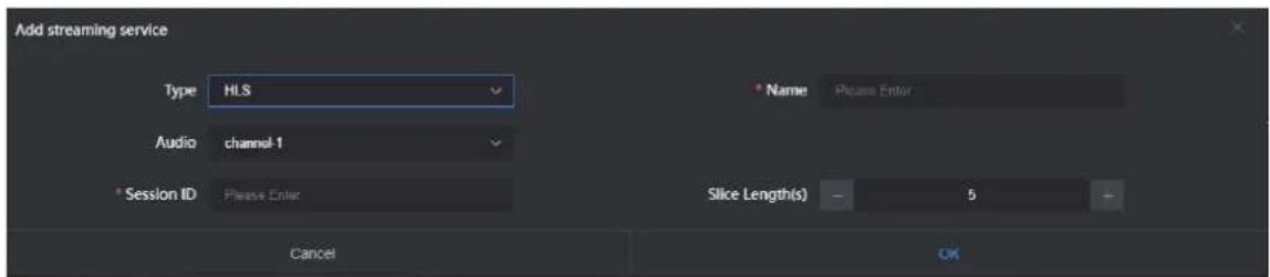
After starting the service, you can get a publishing point of the HLS server. With this stream address, you can use VLC and other decoding devices to decode and play.

8.7 TS-UDP Streaming (Unicast and Multicast)
Click “+” to add a stream service and selects “TS-UDP” as type.
The TS-UDP includes two ways: unicast and multicast. If use unicast, the "Target Address" is the IP address of the device that receives the TS stream, and the "Target Port" is a port that not conflict with the ports of other services, and the "Multicast TTL" does not need to be modified. Unicast can only be decoded and played at the target address. If use multicast, fill a correct multicast address (address range: 224.xxx \~ 239.xxx) in the "Target Address". "Target Port" is a port that not conflict with the ports of other services. For other parameters, if there is no special requirement, it is recommended to use the default.


Note: Multicast can only be decoded and played within the same network segment. Both the encoder and the player need to configure a gateway to decode and play multicast normally.
After the setting is complete, a URL address will be generated in the TS-UDP push bar, which can be decoded and played by decoding devices such as VLC. If the multicast is decoded and played on the computer, the computer needs to close the firewall, and the network needs to configure the gateway.


Note: When the URL obtained by the multicast push stream mode is udp://225.6.6.6:1234, if VLC Player is used to play, an @ symbol needs to be inserted in the URL to play normally, that is udp://@225.6.6.6:1234.
9 User Management
Click setting page>user management, add and delete users, change the password, etc.

10 Area and Time Management
Click "Location & Time" to change the system time of the encoder. If there are no special requirements, please select "Follow current PC" and click "Settings".
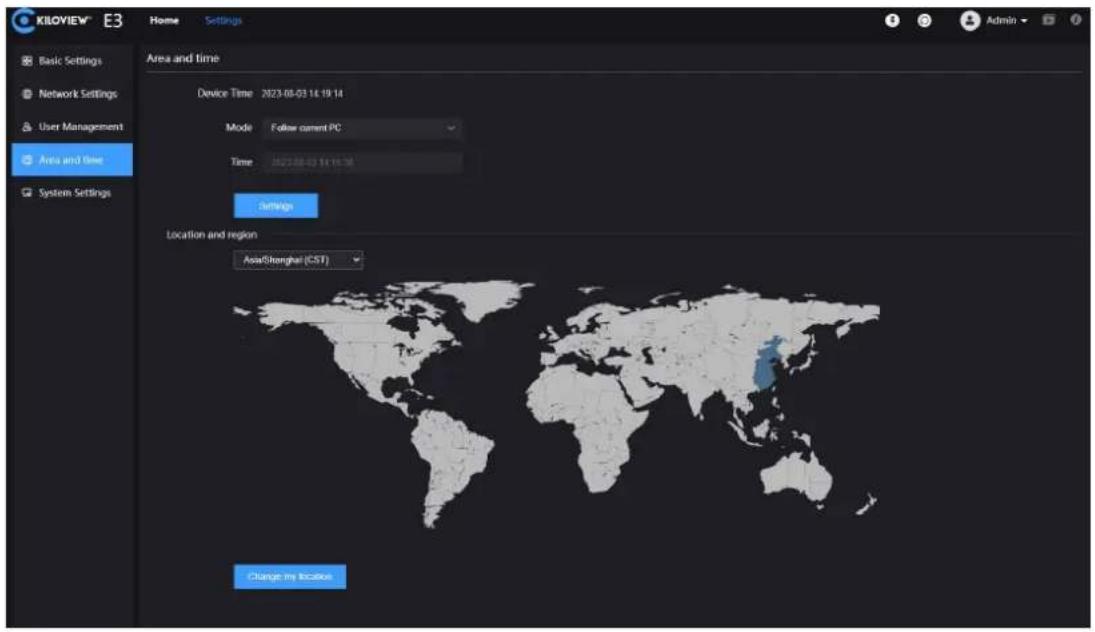
11 System Settings
11.1 Language
Click the language window to switch the system language, currently it supports simplified Chinese, traditional Chinese and English.

11.2 Restore
If your device failed to work because of the parameter changes (the most typical one is failure to log in the device due to network address change), you are suggested to restore the factory settings to default values.
There are two ways to restore the factory settings:
- Web Page "Settings"> "Basic Settings"> "Restore Factory".
- When the device fails to log in to the Web management page normally, enter the Recovery mode of E3 (see Section 11.4.2 for details) to restore the factory settings.
On the first page of the E3 LCD display, press to enter the system settings, select Restore factory, and press to restore factory settings.

11.3 Reboot
Click on the upper right corner of the web page, the device software restarts, which is equivalent to restarting the device, and it lasts about 1 minute.
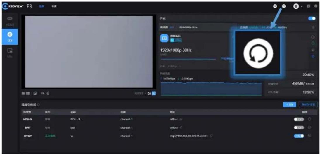
11.4 Firmware Upgrade
Each product undergoes continuous improvement, so we constantly perform functional upgrades and address bugs for our devices. Support for new features or bug fixes for the devices will be delivered in the form of upgrade packages. If necessary, please visit the company's official website's download page to obtain the upgrade package.

Kiloview will continue to provide firmware updates and bug fixes for E3 device
Visit: https://www.kiloview.com/en/support/download/
In the filtered list, select Video Encoders > E3 and find the latest firmware dow the Programs tab.
11.4.1 Web Page for Upgrade
Log in to the E3 management page, click "Settings" > "System Settings" > "Firmware Upgrade" to enter the firmware upgrade page. Check whether the latest software version downloaded is newer than the current software version. If the version is the same or lower, there is no need to upgrade. To upgrade, just upload the firmware file downloaded from the official website, and then click "Firmware Upgrade".
After uploading the firmware successfully, the system will prompt to restart. Click OK, the device will restart. Please wait patiently. After the device restarts, refresh the WEB management page to re-enter the page.

11.4.2 Recovery
When the device cannot log in to the web management page normally, there are three buttons on the LCD display: left and right buttons, the OK button. Connect the power supply, after the LCD display shows KILOVIEW, press and hold the OK button for more than 10s to enter the Recovery mode.
Step 1: Get a USB flash drive and copy the firmware files you downloaded from the official website to it.
Step 2: Insert the USB into E3, after the device is turned on (about 2s), wait for the Kiloview logo to appear on the screen, and hold OK button for more than 10s until the device enters Recovery mode

KILOVIEW ^TM
E3 4K HDMI/3G-SDI Encoder User Manual

Step 3: Click the touch button to select "Recover from USB" (install firmware from USB), and press after the selection is completed to start the upgrade.

Step 4: During the E3 firmware update, the device will prompt "Updating! Please keep the power on."

Step 5: When the screen displays "Firmware updated successfully", it means that the E3 has completed the firmware upgrade. At this time, any operation of the touch button will help you return to the Recovery menu, please select Reboot to restart the device.

flowchart
graph LR
    A["Firmware updated successfully"] --> B["RECOVERY"]
    B --> C["Reboot"]

Note:
During the upgrade process, please do not cut off the power, otherwise the device may fail to start.
Generally, the upgrade process takes about 3-5 minutes. If the upgrade is still completed after 5 minutes, please try to refresh the web page; if you still access normally, please try to contact technical support
If you need to use a USB flash drive to upgrade the firmware, it is recommended that the file system format of the USB flash drive be FAT32.
12 Others
To prolong the device life, please unplug the power and keep it properly if you do not use it for a long time.
Thanks for your reading!
KILOVIEW Electronics CO., LTD
Tel: 86-731-88315979
Website: www.kiloview.com
Support Email: support@kiloview.com
WhatsApp : +86-18573195156/18573195256
Address: B4-106/109, Jiahua Intelligence Valley Industrial Park, 877
Huijin Road, Yuhua District, Changsha City, Hunan Province, China
- User Manual
- Legal Statement
- Contents
- Product Introduction
- Advantages
- ● Professional and rich business functions for broadcast
- production and Pro AV applications
- Packing List and Device Interface
- Packing List
- Device Interface
- Device Indicators
- Installation and Connection
- Video Signal Connection
- Network Connection
- Power Connection
- Display Screen and Touch Buttons
- Use of Touch Buttons
- Use of Display Screen
- Status of Device
- HDMI Video Source Information
- SDI Video Source Information
- Network Status Information
- Login and Network Configuration
- Device Login
- Network Settings for your PC
- WEB management page login
- Network Configuration
- Ethernet
- Advanced Settings
- - HTTP/HTTP Setting
- - Routing Strategy
- Parameter Configuration
- Encoding Mode Selection
- - Mix (mix coding) settings
- - Mix(mix coding) layout settings
- Information Bar
- Video Encoding Parameter
- Audio Encoding Settings
- Audio Signal Source Settings
- Audio Encoding Parameter Settings
- Image and OSD Overlay
- Image Overlay
- OSD Overlay
- Recording
- Note:
- Streaming Service
- NDI|HX
- NDI Discovery Server
- RTSP
- RTMP Streaming (Live Streaming)
- Create new stream key
- Streaming protocol
- Stream resolution
- 2) RTMP Streaming to other platforms
- SRT
- HLS Streaming
- TS-UDP Streaming (Unicast and Multicast)
- User Management
- Area and Time Management
- System Settings
- Language
- Restore
- Reboot
- Firmware Upgrade
- Web Page for Upgrade
- Recovery
- Others
- Thanks for your reading!
- KILOVIEW Electronics CO., LTD
Brand : Kiloview
Model : E3
Category : Server