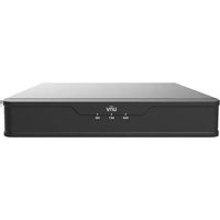
NVR301-08-P8 - VCR UniView - Free user manual and instructions
Find the device manual for free NVR301-08-P8 UniView in PDF.


| Product Type | Network Video Recorder (NVR) |
| Model | NVR301-08-P8 |
| Brand | UniView |
| Channels | 8 channels (8 PoE ports) |
| Video Compression | H.265+ / H.265 / H.264+ / H.264 |
| Recording Resolution | Up to 12MP per channel (depending on camera) |
| PoE Standard | IEEE 802.3af/at, total power budget 120W |
| Hard Drive Support | 1 SATA HDD (up to 10TB) |
| Network Interface | 1 RJ45 10/100/1000 Mbps |
| Remote Access | Via web browser, UniView app (iOS/Android) |
| Dimensions (W x D x H) | 300 x 250 x 50 mm |
| Weight | 2.5 kg |
| Power Supply | 48V DC, 2A (external adapter) |
| Power Consumption | < 10W (without HDD and cameras) |
| Operating Temperature | -10°C to 55°C |
| Mounting | Desktop or rack-mountable (bracket included) |
| Maintenance | Clean with a dry cloth; keep vents unobstructed |
| Safety | Use only provided power adapter; do not expose to moisture |
| Spare Parts | Power adapter, hard drive (not included), mounting bracket |
| Repairability | Hard drive user-replaceable; other repairs by authorized service |
| General Information | UniView NVR301-08-P8 is a 8-channel PoE NVR for IP cameras, supports ONVIF |
Frequently Asked Questions - NVR301-08-P8 UniView
User questions about NVR301-08-P8 UniView
0 question about this device. Answer the ones you know or ask your own.
Ask a new question about this device
Download the instructions for your VCR in PDF format for free! Find your manual NVR301-08-P8 - UniView and take your electronic device back in hand. On this page are published all the documents necessary for the use of your device. NVR301-08-P8 by UniView.
USER MANUAL NVR301-08-P8 UniView
Network Video Recorders
User Manual
V3.02
Contents
About this Manual....1
1 Local Operations....2
1.1 Before You Begin....2
1.2 Local Operations....2
2 Initial Configuration....4
2.1 Preparation....4
2.2 Login....4
2.3 Wizard....9
3 Live View.... 11
3.1 Live View Status....12
3.2 Window Toolbar....12
3.3 Screen Toolbar....14
3.4 Shortcut Menu....18
4 Channel Configuration....20
4.1 Channel Management.... 21
4.1.1 IPC Configuration....21
4.1.2 Fisheye Configuration.... 29
4.1.3 Advanced Functions....31
4.1.4 Camera Type....32
4.2 Audio & Video.... 33
4.2.1 Encoding Settings....33
4.2.2 Audio Configuration....35
4.3 Display Configuration....37
4.3.1 OSD Configuration.... 37
4.3.2 OSD Content.... 38
4.3.3 Image Settings.... 39
4.3.4 Privacy Mask....44
4.4 PTZ Configuration.... 45
4.5 Panoramic Linkage....50
4.6 Radar Configuration....52
5 Search....53
5.1 Recording Backup.... 53
5.2 Image Backup....56
5.3 Event....58
5.4 Object....60
5.4.1 Person Search....60
5.4.2 Motor Vehicle Search....66
5.4.3 Non-Motor Vehicle Search....67
5.5 Statistics....68
5.5.1 People Counting Report....69
5.5.2 Heat Map....70
6 VCA....71
6.1 VCA Configuration....71
6.1.1 Face Recognition....73
6.1.2 Perimeter Protection....77
6.1.3 Object Detection....84
6.1.4 Exception Detection & Statistics....85
6.1.5 Temperature Detection....89
6.1.6 People Counting....91
6.1.7 Plate Detection....94
6.1.8 Alarm-triggered Actions....95
6.1.9 Arming Schedule....103
6.2 Analyzer Configuration.... 104
6.3 Library Management.... 105
6.3.1 Face List.... 105
6.3.2 Work Clothes Library.... 107
6.4 Plate List....107
6.5 Smart Preview....109
6.5.1 Face Recognition....110
6.5.2 Perimeter Protection.... 111
6.5.3 Vehicle Monitoring.... 112
6.5.4 Object Detection....112
6.5.5 People Flow Counting....113
7 Network Configuration....114
7.1 Basic Configuration....114
7.1.1 Network Configuration.... 114
7.1.2 EZCloud.... 115
7.1.3 DDNS....117
7.1.4 Email....119
7.2 Platform Configuration.... 121
7.2.1 SNMP....121
7.2.2 Alarm Service....122
7.2.3 Configure VIID Local.... 123
7.2.4 Configure VIID Server.... 124
7.3 Advanced Configuration.... 125
7.3.1 PPPoE.... 125
7.3.2 Port....126
7.3.3 Port Mapping....127
7.3.4 Multicast....128
7.3.5 FTP....129
7.4 Wireless Local Area Network....131
7.5 Wi-Fi AP....131
7.5.1 Wi-Fi AP.... 131
7.5.2 Wi-Fi Cascade....132
8 System Configuration....133
8.1 General Configuration....133
8.1.1 Basic Configuration....133
8.1.2 Time Configuration.... 135
8.1.3 DST.... 135
8.1.4 Camera Time Synchronization.... 135
8.1.5 Holiday Configuration....136
8.2 Preview Configuration.... 137
8.2.1 Preview Configuration.... 137
8.2.2 Advanced Configuration.... 140
8.3 POS Configuration....140
8.3.1 POS OSD Configuration....140
8.3.2 POS Configuration....141
8.4 User Configuration....143
8.5 Security Configuration.... 145
8.5.1 IP Address Filtering....145
8.5.2 ONVIF Authentication....146
8.5.3 802.1x....146
8.5.4 ARP Protection....147
8.5.5 Watermark....147
8.5.6 Secure Password....148
8.6 Advanced.... 148
8.6.1 Serial Port.... 148
8.6.2 Hot Spare....149
8.6.3 Unit.... 150
9 Storage....150
9.1 Recording Schedule.... 151
9.2 Snapshot Schedule....153
9.2.1 Configure Snapshot Schedule....153
9.2.2 Snapshot Type....154
9.3 Array....155
9.4 Disk Management....159
9.5 Disk Group....162
9.6 Space Allocation....163
9.7 Advanced Settings.... 164
10 Alarm Configuration....165
10.1 Motion Detection.... 165
10.2 Tampering Detection.... 167
10.3 Human Body Detection.... 168
10.4 Video Loss....169
10.5 Alarm Input and Output....169
10.5.1 Alarm Input....169
10.5.2 Alarm Output....171
10.6 Thermal Imaging....172
10.7 Temperature Alarm....174
10.8 Alert.... 174
10.9 Audio Detection....175
10.10 Buzzer....176
10.11 People Present Alarm....177
10.12 One-Key Disarming.... 179
10.13 Manual Alarm.... 180
11 System Maintenance....181
11.1 System Info.... 181
11.1.1 Basic Info....181
11.1.2 Camera Status....182
11.1.3 Recording Status.... 183
11.1.4 Online User....183
11.1.5 HDD Status....184
11.1.6 Decoding Card Status....184
11.2 Network Information....185
11.2.1 Network Traffic.... 185
11.2.2 Packet Capture....185
11.2.3 Network Check....187
11.2.4 Network Status.... 188
11.2.5 Network Resource Statistics....189
11.2.6 PoE and Network Port Status....189
11.3 Log Search....190
11.4 Maintenance.... 191
11.4.1 Maintenance.... 191
11.4.2 Diagnosis Info....192
11.4.3 One-Click Collection....194
11.5 System Upgrade....194
11.5.1 NVR Upgrade.... 194
11.5.2 IPC Upgrade....195
11.6 HDD Check....196
11.6.1 Run S.M.A.R.T. Test.... 196
11.6.2 Bad Sector Detection....197
12 Playback....198
12.1 Instant Playback....198
12.2 Normal Playback....199
12.3 Smart Playback.... 201
12.4 Corridor Playback....203
12.5 External File Playback....203
12.6 Tag Playback....203
12.7 Playback by Search.... 205
12.8 File Management....206
13 Shutdown....207
14 Web-Based Operations....208
14.1 Preparation....208
14.2 Login....208
14.3 Live View....209
14.4 Playback....210
14.5 Configuration....210
14.6 Smart....211
15 Appendix FAQ....211
Copyright Statement
©2022-2023 Zhejiang Uniview Technologies Co., Ltd. All rights reserved.
No part of this manual may be copied, reproduced, translated or distributed in any form by any means without prior content in writing from Zhejiang Uniview Technologies Co., Ltd (referred to as Uniview or us hereafter).
The product described in this manual may contain proprietary software owned by Uniview and its possible licensors. Unless permitted by Uniview and its licensors, no one is allowed to copy, distribute, modify, abstract, decompile, disassemble, decrypt, reverse engineer, rent, transfer, or sublicense the software in any form by any means.
Disclaimer
Due to such reasons as product version upgrade or regulatory requirement of relevant regions, this manual will be periodically updated.
This manual is only for informational purpose, and all statements, information, and recommendations in this manual are presented without warranty.
The illustrations in this manual are for reference only and may vary depending on the version or model. The screenshots in this manual may have been customized to meet specific requirements and user preferences. As a result, some of the examples and functions featured may differ from those displayed on your monitor.
Safety Symbols
The symbols in the following table may be found in this manual. Carefully follow the instructions indicated by the symbols to avoid hazardous situations and use the product properly.
| Symbol Description | |
| [G00X]NOTE! | Indicates useful or supplemental information about the use of product. |
 CAUTION! CAUTION! | Indicates a situation which, if not avoided, could result in damage, data loss or malfunction to product. |
 WARNING! WARNING! | Indicates a hazardous situation which, if not avoided, could result in bodily injury or death. |
1 Local Operations
This chapter introduces operation methods and matters needing attention on the local interface.
1.1 Before You Begin
- Please be aware that functions may vary with NVR model.
- The figures in this manual are for illustration purpose only and may vary with NVR model.
- The parameters that are grayed out on the local interface cannot be edited. The parameters and values displayed may vary with NVR model and version.
1.2 Local Operations
This section introduces mouse operations and front panel buttons.
You can refer to Initial Configuration and complete a quick configuration.

Note: Unless otherwise specified, all operations described in this manual are performed with a mouse by the right hand.
Mouse Operations
Table 1-1: Mouse Operations
| Name Operation | Description | |
| Left button | Click • Select or confirm an item. • Select to edit digits, symbols, uppercase or lowercase letters in a field. | |
| Double-click Switch single window or multi-window in live view. | ||
| Drag • Draw or move a rectangle on the screen. • Sort windows in a multi-window layout. | ||
| Right button Click | • Show the shortcut menu. • Exit digital zoom. • Exit the current window when Cancel or Exit is displayed. | |
| Scroll wheel | Scroll up • Scroll up a list, window, or scroll bar. • Zoom in on the screen when digital zoom is enabled. | |
| Scroll down • Scroll down a list, window, or scroll bar. • Zoom out on the screen when digital zoom is enabled. | ||
| Long press Restore to the lowest resolution. | ||
Front Panel Buttons
The front panel buttons may vary with NVR model.
Table 1-2: Front Panel Buttons 1
| Button Description | |||
 | Display the main menu. | ||
 | Switch to the next tab on the screen or switch the input method. | ||
 | Auxiliary function button. | ||
| Button Description | |||
 | Exit the current window. | ||
 | Direction button: Switch windows or menu items; or control rotation direction of a PTZ camera when the PTZ toolbar is closed. PTZ stands for pan, tilt, and zoom. | ||
 | •  / /  ind or forward 30 seconds in full screen. ind or forward 30 seconds in full screen. | ||
 |  | •  / /  able-speed forward or rewind in full screen. able-speed forward or rewind in full screen. | |
 | Confirm an operation, or start/pause the playback. | ||
 | Long press at least 3 seconds to start up or shut down the NVR.Note: For certain devices, you can press and hold this button for at least 3 seconds to start the device. | ||
Table 1-3: Front Panel Buttons 2
| Button Description | |
 | Enter 1; or display the main menu. |
 | Enter 2, A, B, or C; or start instant playback. |
 | Enter 3, D, E, or F; or start manual recording. |
 | Enter 4, G, H, or I; or enter the PTZ control interface. |
 | Enter 5, J, K, or L; or switch the screen layout in live view or playback mode. |
 | Enter 6, M, N, or O; or enable or disable arming. |
 | Enter 7, P, Q, R, or S; or take a snapshot. |
 | Enter 8, T, U, or V. |
 | Enter 9, W, X, Y, or Z. |
 | Enter 0 or a space. |
 | Delete. |
 | Switch the input method. |
 | Auxiliary function button. |
 — — | Exit the current window. |
— — — | Switch to the next tab. |
 | Switch windows or menu items; or control rotation directions of a PTZ camera when the PTZ toolbar is closed. PTZ stands for pan, tilt, and zoom.Rewind or forward 30 seconds in full screen.Variable-speed forward or rewind in full screen.: Confirm an operation, or start/pause the playback. |
 | Long press at least 3 seconds to start up or shut down the NVR.Note: For certain devices, you can press and hold this button for at least 3 seconds to start the device. |
2 Initial Configuration
This chapter describes the initial configuration of the NVR.
2.1 Preparation
- Make sure that at least one monitor is correctly connected to the VGA or HDMI interface on the rear panel of the NVR, otherwise, you cannot view the local interface.

Note: If no images are displayed after the NVR is powered on, it may be because the monitor does not support the current output resolution of the NVR. Please press and hold the scroll wheel of the mouse to restore to the lowest resolution.
- Make sure that the hard disk(s) are correctly installed. For detailed installation steps, please refer to the quick guide shipped with the NVR.
2.2 Login
Device Login
- Select the desired language after startup.

- On the Login page, select the default user (admin), enter the default password (123456), and then click Login.


Note: If you enable Remember Password, the username and password will be automatically filled in the next time.
- Click Yes in the pop-up window to change the password into a strong one.
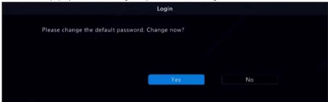
- On the Change Password page, enter the old password, new password, and confirm the new password. You may check Email to enter your email address, and then click OK.


Note:
- Use the default username and password (admin/123456) to log in for the first time. After login, you have to change the password, and use the new password to log in the next time.
- For security, you are strongly recommended to set a strong password with at least 9 characters including all three elements: letter, digit, and special character.
-
It is recommended to enter your email address in case you need to reset the password. You may also enter it when you need to retrieve the password. See Reset Password for details.
-
The Password Sync Attention dialog box appears. Select the checkbox below as needed, and then the new NVR password will be synced to all the online cameras via the Plug & Play.

- (Optional) Set an unlock pattern, or click Skip to proceed.


Note:
- You can set the unlock pattern later at anytime or disable it under Menu > System > User.
- If an unlock pattern is set, it will replace the password at login.
Reset Password
- If you forgot the admin password or want to reset the password, click Forgot Password on the login page.

- (Skip this step if you have already entered your email address) Enter your email address so as to receive the security code, that is, the temporary password.

- Follow the instructions on the screen to obtain the security code.

Note: The app may vary with NVR model.
- Enter the security code received from the email address, and click OK.
- Enter the password, and confirm the password, and then click OK to reset the password.

- Use the new password to log in again.
2.3 Wizard
The wizard page appears after you login. Follow the wizard to complete the most basic setup, or click Exit to skip this step.
Note: You can also go to Menu > System > General > Basic Setup to set the basic parameters.
- Scan the QR code and follow the on-screen instructions to add the NVR to your app, and then click Next or click 2. This page shows the network connection status.

• Network connected:

flowchart
graph LR
    A["Server"] <--> B["Cloud Icon"]
• Network unconnected:

- Set the time parameters, including time zone, date format, time format, and system time, and then click Next.
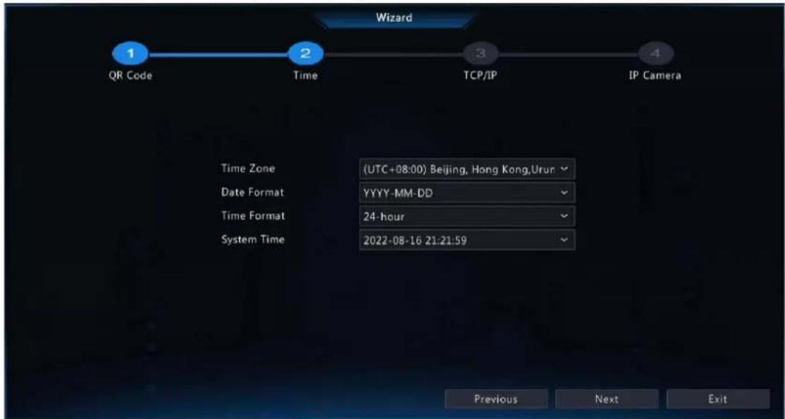
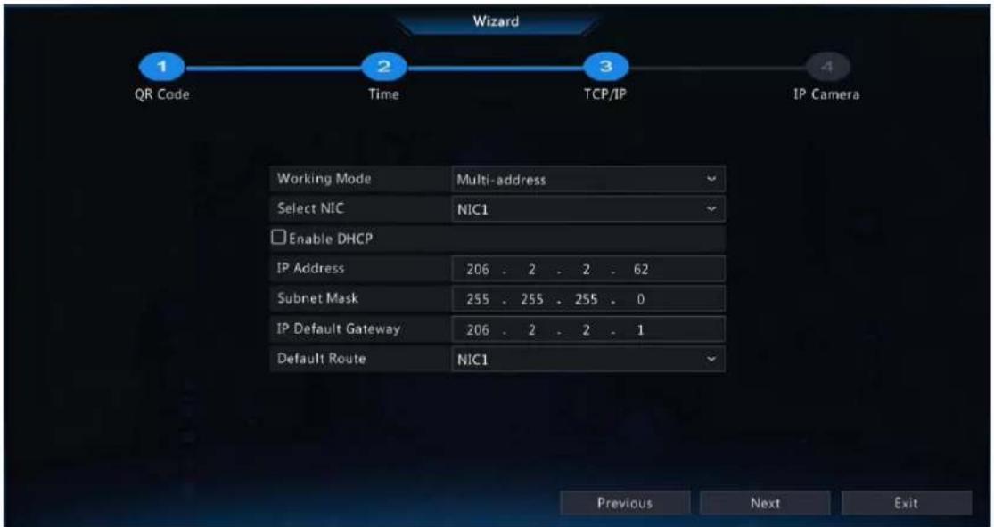
- Configure TCP/IP. Select the working mode and NIC. Check Enable DHCP to automatically obtain the IP address, subnet mask and IP default gateway. You can also enter the information manually. Then, click Next.
- Add IP devices. Select the IP devices to add in the discovered device list, and click Add.


Note:
• To add IP devices through PoE ports, see Option 6: Connect via Cable in Add IPC for details.
- The added IP devices can go online and start live view only if the password is still the default password. If the password has been changed, you need to enter the correct password for the camera to go online.
- If the desired IP device is not in the device list, you may add it in a preview page or under Menu > Camera > Camera > Camera. See Channel Management for details.
- Click OK.
3 Live View
This chapter introduces the live view page, including window toolbar, screen toolbar, shortcut menu, digital zoom, sequence operation, etc.

Note: The operations may vary with NVR model.
3.1 Live View Status
The following icons are used to indicate alarms, recording status, and audio status in a live view window.
Table 3-1: Live View Window Icons
| Icon Description | |
 | Tampering |
 | Recording |
 | Two-way audio |
 | Alarm |
3.2 Window Toolbar
Click a window to display the window toolbar for quick configuration.
Table 3-2: Window Toolbar
| Button Name Description | ||
 | PTZ Control • Available | for PTZ cameras only. Click to display the PTZ control window.You can also configure PTZ under Menu > Camera > PTZ. See PTZ Configuration for details. |
 | Fisheye Mode Set the | mount mode and display mode for fisheye cameras. This button appears only for fisheye cameras. |
 | Local Recording | Record live video in the window to the hard disk. Click to stop recording.Note: Similar to manual recording, local recording is a scheduled recording and has higher priority over other video recording schedules. You can play the local recording in normal mode. |
 | Instant Playback Click | to play the video recorded during the past 5 minutes. |
 | Digital Zoom | Zoom in on an area of interest in the window. See Digital Zoom for details. |
 | Image Settings • Click | to set the image mode and parameters so as to get optimal images in the window.You can also edit image settings under Menu > Camera > Image > Image Settings. See Image Enhancement for details. |
 | Take Snapshot Click to | take a snapshot. The window borders will flash white. You may view and back up snapshots under Menu > Backup > Image. |
 | OSD • Click to set OSD. | You can also set OSD under Menu > Camera > OSD. See Display Configuration for details. |
 | Two-way Audio | Start two-way audio with the camera. The sound volume is adjustable. Click to stop.Note: Correct audio input and output (AUDIO IN/OUT) connections between NVR and IPC are required. |
 | Turn Audio On | Click to turn on audio. The sound volume is adjustable. Clickto turn off audio.Note:When you turn on audio in the current window, audio of the previous window is turned off. |
| [XXXXY] | Quick IPC Disarming | The iconears when an alarm occurs. If the alarm comes from a connected IPC, you can clickto cancel the action(s) configured for the IPC. |
 | Camera Info Hover over the button to view the bit rate of the current window; click the button to view the camera information, change the user name or password. | |
Digital Zoom
Zoom in on an area of images in a window for details.
- On the preview page, click the window, and then click on the window toolbar.

- Move your mouse to the area you want to zoom in on, then use your scroll wheel to zoom in. The enlarged image is as follows.

natural_image
Aerial view of three cars parked on a wet road with trees and a paved area in the background (no visible text or symbols)- Right-click to exit zoom.
3.3 Screen Toolbar
Move your mouse to the bottom of the preview page to display the screen toolbar. Click to lock the toolbar.
Table 3-3: Screen Toolbar
| Button Description | |
 | Click to select menu, playback, logout, restart, shutdown. |
 | Select the screen layout, including single window and 4/6/8/9/16/25/36 windows. |
 | Previous or next screen. |
 | Start or stop sequence. SeeSequencefor details. |
 | Click to go to thePlaybackpage. |
 | Click to go to theFace Recognitionpage. SeeFace Recognitionfor details. |
 | Click to go to theVehicle Recognitionpage. SeeVehicle Recognitionfor details. |
 | Switch to multi-sensor preview mode. SeeMulti-Sensor Previewfor details.Note:This function is only available for dual-channel cameras. |
 | Click to go to theEpidemic Controlpage. For temperature measurement results, seeThermal Imagingfor details. |
 | Click to display the cloud service window. You may scan the QR code and download an app to manage your NVR.Note:This function is only available to certain NVR models. |
 | Click to view camera information, including camera status and alarm status. |
 | Click to view NVR alarm and camera alarm. |
 | Show device time. Hover over the button to view the date; Click to edit time settings. |
 | Lock/hide the screen toolbar. |
Sequence
Use sequence when you want to view live videos from different cameras at the same time and ensure the image clarity. The function requires you to configure the screen layout, windows, linked cameras, and the sequence interval.
The following example describes how to configure sequence for five cameras based on a 4-window screen layout.
- On the preview page, right-click and select Multi-Window > 4 Windows.

natural_image
Composite image showing urban infrastructure, a residential building, and a police station with pedestrians (no visible text or symbols)Note: The number of windows that can be displayed may vary with NVR model.
- Click on the screen toolbar to start sequence.
The system starts to display images of four cameras in four windows on the first screen, and then displays the fifth camera' image on the second screen after the set interval.

natural_image
Exterior view of a modern building with parked cars and greenery (no visible text or signage)Note: The default sequence interval is 8 seconds. You can set it under Menu > System > Preview. See Preview Configuration for details.
- Click to stop sequence.
Face Recognition
To view face snapshot records, you need to configure Face List, Face Comparison, and Face Detection first.
- Click on the screen toolbar.
In this page, you can view the historical face comparison records on the left, and view face snapshots, snapshot details, and prompt message on the right. 1 view is displayed by default, and you can switch to 4 or 9 views to view more face snapshots in the page.

- Click configure face recognition parameters, and then click OK.

| Item Description | |
| Page Name The default is face | recognition. Set it as needed. |
| Match Message If the face has | a match in the face library, the default match messageWelcomeappears. You can customize the message as needed.Click Hide, the page will not show the match message. |
| Unregister Message If the face | does not have a match in the face library, the default messageStrangerappears. You can customize the message as needed.Click Hide, the page will not show the message. |
- Click □ exit the face recognition page.
Vehicle Recognition
To view vehicle recognition details, you need to configure Plate List and Plate Comparison first.
- Click on the screen toolbar, and then you can view pass-through records, vehicle snapshot information, etc.

- Click C exit the vehicle recognition page.
Multi-Sensor Preview
This function is only available to dual-channel cameras that support Panoramic Linkage.

| Button Description | |
 | Drag to zoom. Drag to select a specific area in the left panoramic image, and then the corresponding area will be linked and magnified in the right close-up image. |
 | Track manually. After configuring detection rules forPerimeter Protectionfunctions, when the camera detects moving objects (motor vehicle/non-motor vehicle/pedestrian) in the detection area, you can click the bounding box in the left window to zoom in on and track the object in the right window.Note:To use this function, enablePanoramic Linkageon the Trigger Actionspage of perimeter protection functions. SeeCamera Linkagefor details. |
 | Click to link. Click anywhere in the left panoramic image, and then the right close-up image will move to the corresponding position. |
 | PTZ configuration. Configure and control PTZ cameras.Note:To use this function, the channel 2 should be a PTZ camera. SeePTZ Configurationfor details. |
 | Previous screen. |
 | Next screen. |
 | Exit the multi-sensor preview. |
3.4 Shortcut Menu
A shortcut menu as shown below appears when you right-click in a window.

Shortcut Menu
Table 3-4: Shortcut Menu
| Item Description | |
| Menu Display the main menu. | |
| Common Menu | Go to the Camera, Network Config, and Backup page. |
| Single Window Switch to single window. | |
| Multi-Window Select the screen layout, including 4/6/8/9/16/25/36 windows. | |
| Corridor Display video images in corridor mode. You can set the number of windows from the Preview Windows drop-down list under Menu > System > Preview. See Preview Configuration for details.Note:To display images in corridor mode, make sure the camera is installed correctly (rotated 90° clockwise or counterclockwise), and then set the Image Rotation parameter under Menu > Camera > Image to rotate images accordingly.When a channel is in corridor mode, all the operations (such as digital zoom and drawing motion detection area) are performed in corridor mode.Wide mode Switch to the wide mode. Support the screen layout of 2/3/6/7/8/9/12 windows. | |
| Main/Aux Monitor Switch live video from different video outputs. Press and hold the right mouse button to switch between main monitor and auxiliary monitor. | |
| Playback Play the video of the current day for the camera linked to the current window. You can also choose to play videos from other days as needed. | |
| Preview Mode | Switch between Normal and Smart. The default is Normal mode. |
| VCA Search Search the VCA snapshots and recordings on the Search page. | |
| Light Config Set image parameters for the selected camera, including image enhancement, smart illumination, exposure, white balance, and advanced configuration. See Image Settings for details. | |
| Output Mode Choose a video output mode, including standard, soft, bright, vivid, and custom. Brightness, saturation, and other parameters are also configurable. | |
| Manual Manual settings include manual recording, manual snapshot, and manual alarm, buzzer, let through manually. See Manual Operations for details. | |
Manual Operations
Manual operations include manual recording, manual snapshot, manual alarm, buzzer, and let through manually. Manual Recording

Note: Similar to local recording 📄 on the screen toolbar, manual recording is a scheduled recording and has higher priority over other recording schedules. You can play manual recordings in normal mode.
- Right-click and select Manual > Manual Recording.
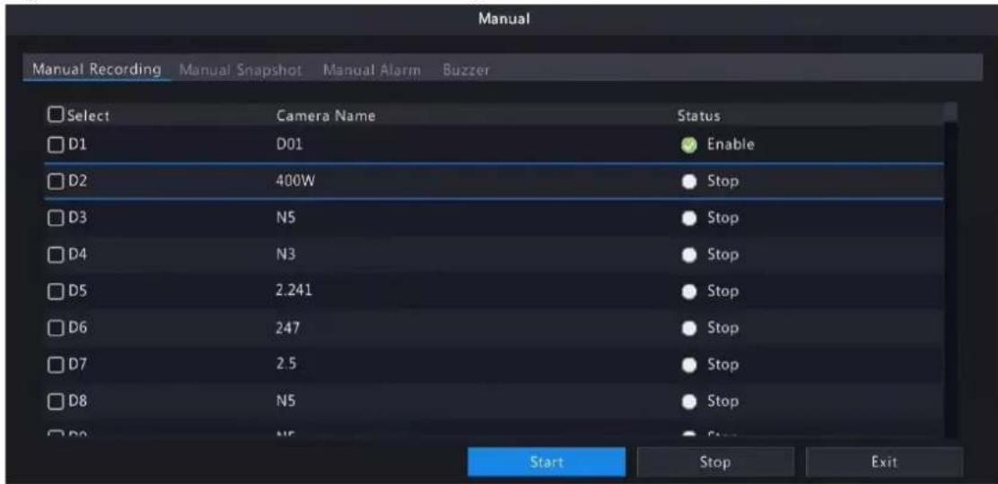
- Start or stop manual recording.
- Start recording: Select the desired camera(s) and then click Start.
- Stop recording: Select the camera(s) being recorded and then click Stop.
Manual Snapshot
- Right-click and select Manual > Manual Snapshot.

-
Start or stop manual snapshot.
-
Start snapshot: Select the desired camera(s) and then click Start.
- Stop snapshot: Select the camera(s) that has enabled snapshot, and click Stop.
Manual Alarm
Right-click and select Manual > Manual Alarm. You can trigger or clear an alarm output manually. See Manual Alarm for details.
Buzzer
Right-click and select Manual > Buzzer. You can stop the buzzer manually. See Buzzer for details.
Let Through Manually
If a license plate not match alarm occurs, and the IPC cannot lift the barrier automatically, you can trigger the IPC to lift the barrier manually on the NVR side as needed.

Note:
- This function requires you to configure plate not match alarm first. See Plate Comparison for details.
-
This function is available to cameras that support controlling barrier gates.
-
Right-click and select Manual > Let Through Manually.
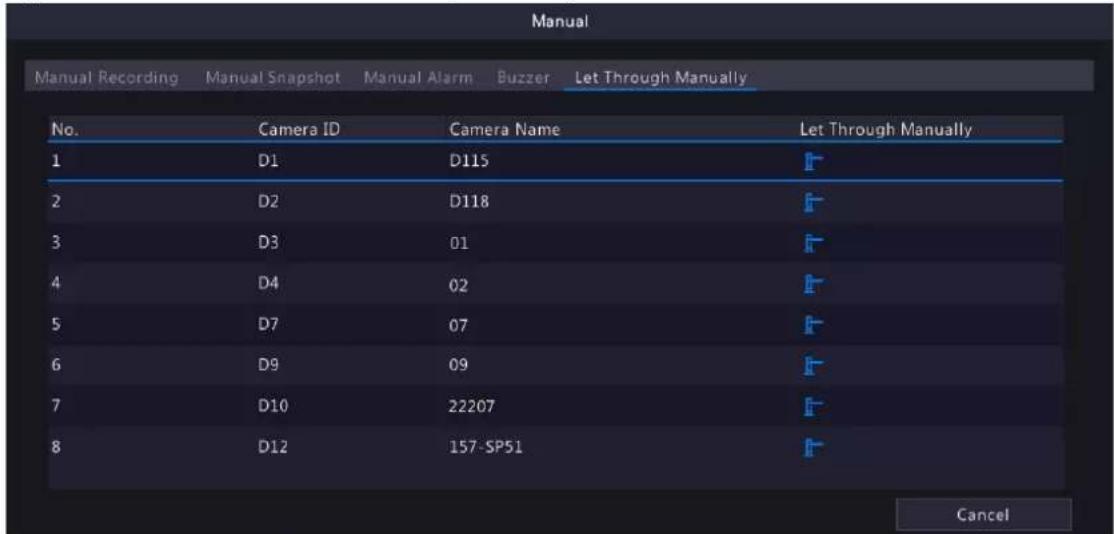
- Click the corresponding and trigger the camera to lift the barrier.
4 Channel Configuration
Configure IPC, encoding, audio, snapshot, OSD, image, privacy mask, and PTZ parameters.

Note: The IP devices mentioned in this manual mainly refer to IP cameras (or network cameras).
4.1 Channel Management
Manage IP cameras.

Note:
- Before you start, make sure the IP cameras are connected to your NVR via network.
- An IP camera should be connected to one NVR only. An IP camera managed by multiple NVRs may cause unwanted issues.
4.1.1 IPC Configuration
Add and manage IP cameras.
Go to Menu > Camera > Camera > Camera.
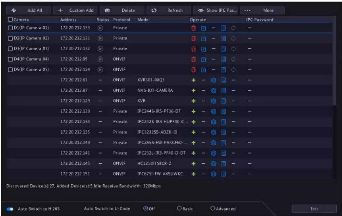
Add IPC
The system automatically searches for IP cameras and lists the discovered. Click Refresh, the system refreshes the list and IPC status. Choose a way to add IPCs.
- Option 1: Custom Add
- Click Custom Add.

- In the window displayed, enter the IPC's IP address and complete other settings, then click OK. You may check the camera's status.
• : Camera online.
• : Camera offline. Point to the icon to view the failure information.
• ①: The camera is added to another NVR.
- Repeat the above steps to add other IPCs.
- Option 2: Search Segment
- Click, and select Search Segment.
- Enter the start and end IP addresses, and click Search. The discovered IP devices are listed.

- Select the desired camera, click add it to the NVR.
- Option 3: Add All
Click Add All to add all the discovered IPCs (if not exceeding the upper limit).
- Option 4: Click +
Click to add the camera directly.
- Option 5: Add from the Preview Window
Note: This option is not applicable to NVRs with PoE ports.
- On the preview page, click a window to go to the Add IP Camera page.
- Select the desired IP camera and then click OK.
- Option 6: Connect via Cable
-
Connect an IP camera to a PoE port or a switching port of the NVR with a network cable. The connected camera will be added to the NVR automatically.
-
Check the camera status under Menu > Camera > Camera > Camera.

Note:
- This option is only applicable to NVRs with PoE ports, and the added camera cannot be deleted.
• If you want to add an IPC that is not connected to the NVR's with a network cable, click

change Plug-and-Play to Manual, and complete other parameters.
- For NVR with PoE ports only, ☒ appears under Status if the power output from a PoE port is below or above the rated power of the connected camera.
- Option 7: Add from Another Network
Use this option when the NVR and the IP camera are connected to different routers. Make sure the NVR can access the camera via the camera's public IP address and mapped port number.

Note: First you need to enable port mapping under Setup > Port > Port Mapping on the IP camera's Web interface.
- Option 8: Use Custom Protocol

Note:
- Use this option when the IP camera supports the standard RTSP.
-
Only live and recorded video streams are available from the camera added in this way. Configuration operations are not supported.
-
Go to Menu > Camera > Camera > Camera.
- Click Custom Add. Select Custom from the Protocol drop-down list.
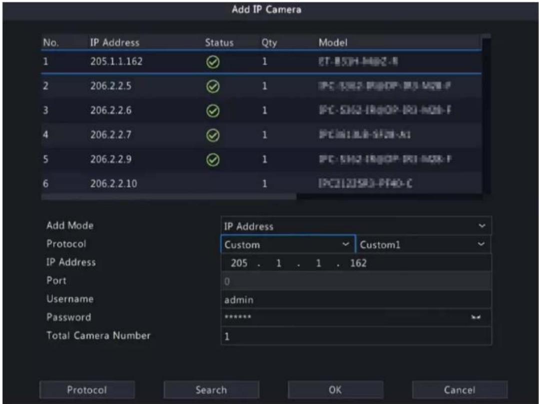
- Click Protocol.
![Protocol Custom Custom1 Protocol Name Custom1 Port 7891 Transfer Protocol UDP Enable Main Stream Resource Path rtsp://:/hjt Enable Sub Stream Resource Path rtsp://:/ Example : rtsp://:/; One channel: rtsp://192.168.0.1:554/unicast/c1/s0/live Multi-channel: rtsp://192.168.0.1:554/unicast/c[%C]/s0/live Add selected camera ID rtsp://192.168.0.1:554/unicast/c[%C+1]/s0/live Add selected camera ID+1 rtsp://192.168.0.1:554/unicast/c[%C+1]/s0/live Add selected camera ID-1 [%C±N] : %C means the remote camera ID selected, N means offset Apply OK Cancel](/content/2026/06/1364532/images/09d008e33501ae67a12e43813e6a3dde8ba748d2b49251364d1a9a477f3cc9ac.jpg)
- Set the protocol name, enter the RTSP port number, transmission protocol, resource paths, etc., and then click OK.

Note: Contact the camera manufacturer for resource paths of main stream and sub stream.
- Enter the IP address, username, and password, and then click OK. Check status in the camera list.
Edit IP Camera
Option 1
Select the target camera and click edit the settings as needed, and then click OK.


Note:
- To change the IP camera connected to the channel, you can edit the IP channel related parameters (except IP address), or directly click another camera in the list above.
- The configuration items may vary with IPC model.
Option 2
- If the username and password input for an IPC is incorrect, the live view window will show the cause, and you can change the username and password in the live view window.
Camera Offline

Incorrect username or password)
- Click find modify username or password.

- Click OK and then check the status of camera. I means the camera is online.
Delete IP Camera
You can delete IP camera(s) one by one or in batches.

Note: Cameras corresponding to PoE ports or switching ports cannot be deleted.
- Select a camera to be deleted, click and click OK in the pop-up window.
- Select cameras to be deleted, click Delete, and click OK in the pop-up window.
Network Configuration
Select the camera, and click Edit the IP address, IPv4 subnet mask, IPv4 default gateway for the camera. Click Apply.


Note: - indicates the camera does not support changing network settings.
IPC Password
Show or hide the login password of connected IPCs.
1.
Click . Show IPC Pas...

- On the Authentication page, enter the login password of the admin user.

Note:
- Only admin can set to display or hide IPC password.
-
Click to display the password in clear text.
-
Click Apply.
- If the password is correct, it will automatically return to the IPC configuration page, and IPC password will be displayed in clear text.


Note: Click to hide PC passwords.
- If the password is incorrect, a message will appear, and you cannot display IPC passwords.
More Info
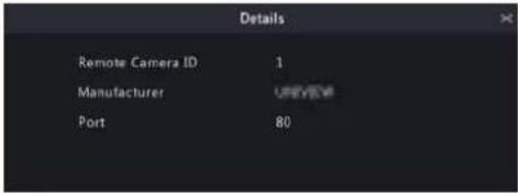
Select the channel, and click to view the detailed information, including remote camera ID, manufacturer, and port number.
Change Window Position
Use this function to change window position of channels on the preview page, without changing the channel ID, IP address, and display order in the channel list. Choose a way to change window position.
- On the multi-window preview page, drag a window to another window to swap their positions.
- On the Preview Configuration page under Menu > System > Preview, change window positions on the preview page. See Screen Configuration for details.
Sort Camera
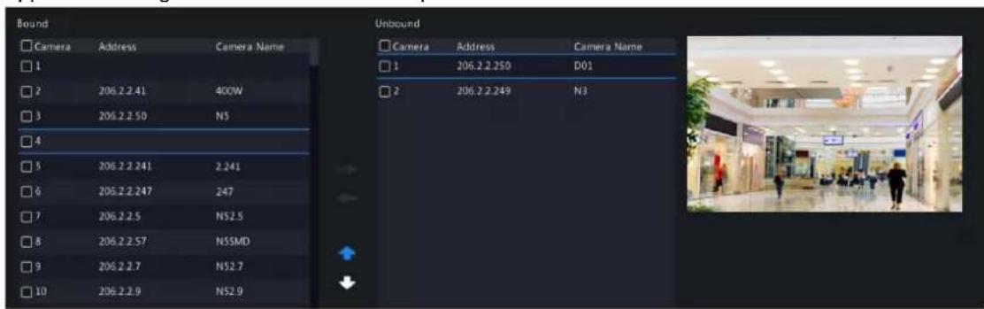
Use this function to change a camera IP bound to a channel. This will not only change the camera's position in the camera list, but also change the position of the camera's live view window. The following example describes how to switch camera 1 and camera 4.

Note:
- This function is not available to NVRs with PoE ports or switching ports.
- This section describes how to sort cameras on an NVR with more than 32 channels. For NVRs with 32 channels or less, you can sort cameras by dragging the mouse.
1. Click, select Sort Camera.

- In the left list, select the check box for camera 1 and click Then camera 1 with IP 206.2.2.250 now appears in the right list. Perform the same operations to camera 4.
- In the right list, select the camera 4 with IP 206.2.2.249 and click 📋 when camera 4 appears at the previous line of camera 1 in the list. Perform the same operations to camera 1, so camera 1 appears at the previous line of camera 4 in the list.
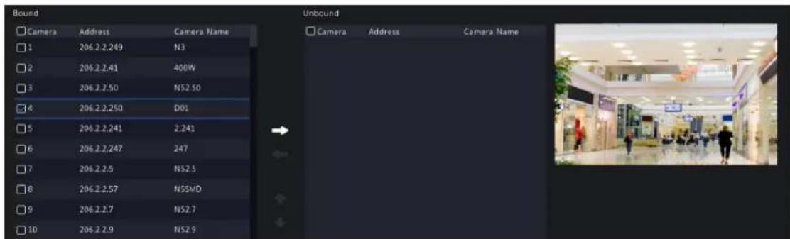
- Click Apply. IPs of camera 1 and camera 4 are swapped, and the position of preview window will also be swapped. Repeat the above steps to sort other cameras.

Note:
- Click to move up or move down the current highlighted camera (not the selected camera).
- To move a camera left, select a corresponding check box in the left list first; otherwise the camera will be inserted to the first blank line.
- The settings cannot be saved when the right list is not empty. You need to clear the list first.
Batch Change Password
When multiple IPCs are not added successfully due to incorrect password, and if the login passwords of these cameras are the same, use this function to change the passwords in batches.

Note:
- This function only changes the password used to add cameras. It does not change the cameras' login password.
-
This function is only applicable for IPCs with the same login password. If one of the cameras still fails to be added after you change the password, it means the camera's login password is different, and you need to change the password separately.
-
Select the cameras with the same password. Click ... More, and select Batch Edit Password.

- Enter the new password and confirm the password.
- Click OK.
Other Operations
| Item Description | |
| Auto Switch to H.265 When enabled, the NVR automatically chooses H.265 for a newly added camera.Note:Every time a camera is added to the NVR, it is considered a newly added camera. This function is not effective to cameras that are already added or added cameras that go back online after being offline.This function is enabled by default on some NVR models. | |
| Auto Switch to U-Code | Select Basic or Advanced, then the NVR automatically chooses basic U-code mode or advanced U-code mode for a newly added camera.Note:Every time a camera is added to the NVR, it is considered a newly added camera. This function is not effective to cameras that are already added or added cameras that go back online after being offline.This function is enabled by default on some NVR models. |
| Refresh Click Refresh to check the camera status. | |
| Live View | Click play live video of the camera. |
4.1.2 Fisheye Configuration
Set the mounting mode and display mode for fisheye cameras. Fisheye configuration is supported only by certain fisheye cameras.

Note: Before using this function, make sure that a fisheye camera has been mounted and that the camera has been added to your NVR.
Configuration
Configure the following parameters after the fisheye camera is installed.
- Go to Menu > Camera > Camera > Fisheye.

- Select the fisheye camera and click


- Set the parameters as needed.
| Item Description | |
| Mount Select the mounting mode, including ceiling mount, wall mount, and desktop mount. If you change how the fisheye camera is installed, change its mounting mode so as to display proper images. | |
| Angle of View (°) Set the viewing angle of the fisheye camera. | |
| Fisheye Mode The display mode of the current camera in the live view window. Set it as needed. | |
- Click Apply.
Dewarping
Fisheye cameras provide large wide-angle views, but the image captured is distorted. You may adjust the output image by correcting the shooting angle of the fisheye.

Note: Dewarping is available in live view and playback (in normal and corridor playback modes). The operations are similar. The following describes dewarping in live view.
- On the preview page, click on the window. The figure as shown below appears.

- Set the mounting mode and display mode.
| Mount Display Mode Description | |||
| Ceiling Mount |  | [TKKT] | 360° panoramic original image |
| Desktop Mount |  |  | 360° panoramic + 1PTZ |
 | 180° panoramic | ||
 | Fisheye + 3PTZ | ||
 | Fisheye + 4PTZ | ||
 | 360° panoramic + 6PTZ | ||
 | Fisheye + 8PTZ | ||
| Wall Mount |  | 360° panoramic original image | |
 | Panoramic | ||
 | Panoramic + 3PTZ | ||
 | Panoramic + 4PTZ | ||
 | Panoramic + 8PTZ | ||
- Dewarping operations: Take Ceiling Mount and Fisheye+3PTZ as an example.

natural_image
Four-panel black-and-white photo collage showing a metallic spherical object with bright light reflections, possibly a spacecraft or spacecraft (no visible text or symbols)- Drag the mouse to rotate the image or use the scroll wheel to zoom in or out on a PTZ image. A box appears on the fisheye image as the image rotates, and as you drag the box or move the scroll wheel on the fisheye image, the corresponding PTZ image rotates or zooms in or out as well.
4.1.3 Advanced Functions
Change the password of online IP cameras or restore factory default settings for cameras.

Note: Changing camera password is available for cameras connected via the private protocol.
Go to Menu > Camera > Camera > Advanced.
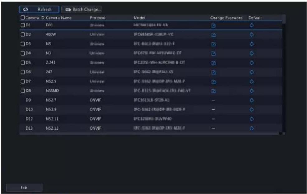
Change Camera Password
You can change password of camera(s) one by one or in batches.
- Select a camera and click 📋, or select the target cameras and click Batch Change Password.

- Enter the new password and confirm the password.
Note: Select Use Admin Password, the camera's password is changed to the admin password of the NVR, and cannot be edited.
- Click OK. Check if the password is successfully changed.
Select the camera, click 📄. A message indicating camera restart appears, click OK and then the camera's default settings will be restored.
4.1.4 Camera Type
You can change the camera type to analog or digital. This function is only available for hybrid NVRs.
Change Camera Type
Change camera type to analog or digital.
- Go to Menu > Camera > Camera > Camera Type.

- Select the camera you want to change and choose the desired type.
- Click Apply, then a message indicating device restart appears.
- Click Yes. The camera type will be changed after the NVR restarts.
Add Analog Camera
Analog cameras can be added to hybrid NVRs only.
- Connect the camera to the video output interface of the NVR via a coaxial cable, and connect the camera to power. The camera will be added to the NVR.
- Check the camera status on the preview page.
4.2 Audio & Video
Configure encoding and audio parameters.
4.2.1 Encoding Settings
Configure storage mode, capture mode, stream type, etc.

Note:
- The configuration items may vary with IPC models or versions.
-
Some functions may be unavailable if the IPC version is too low. In this case, you need to upgrade the IPC first.
-
Go to Menu > Camera > Audio & Video > Encoding.

-
Select the camera from the drop-down list.
-
Choose a storage mode, including main stream, sub stream, main and sub stream, main and third stream, sub and third stream. The default is main and third stream. Only certain NVR models support all the five modes. The storage mode determines the recording format (HD or SD). It may affect the clarity and output mode of the recording. Set the storage mode as needed by referring to the table below.
Table 4-1: Storage Mode
| Storage Mode HD Streaming SD Streaming | |
| Main stream Main stream No video or image | |
| Sub stream Sub stream No video or image | |
| Main + sub stream Main stream Sub stream | |
| Main + third stream Main stream Third stream | |
| Sub + third stream Sub stream Third stream | |

Note: This configuration item only changes the storage stream of the NVR, and does not change the video stream sent from IPC. The IPC sends the main stream by default.
-
Set the capture mode, that is, combinations of resolution and frame rate. This parameter is configurable only when the camera is connected to the NVR via the private protocol.
-
Set the encoding parameters for different streams.
| Item Description | |
| Stream Type | Main stream: Select Schedule or Event.Schedule: Set encoding parameters for scheduled recordings.Event: Set encoding parameters for events such as motion detection and alarm input.Sub stream: Set encoding parameters for low resolution videos intended for network transmission. |
| Video Compression Choose H264 or H265. The supported video compression may vary with IPC model. | |
| Resolution The number of pixels in a frame. | |
| Bitrate Type | VBR: Variable Bit Rate (VBR) is used to keep the quality of video streams as constant as possible by varying the bit rate.• CBR: Constant Bit Rate (CBR) is used to keep a specific bit rate by varying the quality of video streams. |
| Bit Rate(Kbps) The number of bits transferred per second. Select a value from the drop-down list, or selectCustomto set a value as needed. | |
| Frame Rate(fps) The number of frames per second. | |
| Image Quality | This parameter is configurable whenBitrate Typeis set to VBR. 1 to 9 levels are available. |
| I Frame Interval The number of frames between two adjacent I frames. | |
| Smoothing Use the slider to control the sudden change of bit rate. | |
| U-Code Select the U-Code mode, including basic mode and advanced mode. The advanced mode achieves higher compression ratios. You can also turn off the U-Code. | |
- (Optional) To apply the settings to other camera(s), click Copy and select the desired parameter(s) and camera(s), and then click OK.


Note:
- When you copy Storage Mode to other camera(s), if the target camera does not support the storage mode, the operation will fail.
- When you copy Video Compression and U-Code to other camera(s), Bit Rate will be selected automatically because video compression adjusts bit rate automatically.
-
Some parameters cannot be selected at the same time.
-
Click Apply.
4.2.2 Audio Configuration
Configure audio input and audio output of the IPCs.
- Go to Menu > Camera > Audio & Video > Audio.

- Select the desired camera from the drop-down list.
- Configure audio input parameters.
| Item Description | |
| Audio Input | Check ☑ enable audio input. |
| Access Mode Select the access method according to the IPC's audio interface, including Line, Mic, and RS485.• Line-in: The IPC is connected to a sound pickup by a 3.5mm audio cable.• Mic-in: The IPC is connected to a microphone.• RS485: The IPC is connected to a sound pickup by a RS485 cable. You need to set the port mode to sound pickup on the IPC's web interface.See Network Camera User Manual for details.Note: Only certain brands of sound pickups are supported by IPCs.Contact technical support for details. | |
| Input Volume Drag the slider to adjust the audio input volume. | |
| Audio Compression Select the audio compression, including G.711A, G.711U, AAC-LC. The supported audio compression may vary with IPC model. | |
| Sampling Rate(KHz) Select the sampling rate based on the audio compression.• For AAC-LC, select 8 KHz, 16 KHz, or 48KHz.• For G.711A or G.711U, select 8KHz or 16KHz. | |
| Noise Suppression | Select ☑ enable noise suppression. |
| Audio Channel 1/Audio Channel 2 | Select ☑ enable audio channel 1 or audio channel 2, and then select the access mode from the drop-down list.Note: Only certain dual-channel IPCs support two audio channels, but the two audio channels cannot be enabled at the same time. |
- Configure audio output parameters. Only certain IPC models support audio output.
| Item Description |
| Audio Output Select the audio output mode. • Speaker: The default mode. |
| • Line: An external speaker or earphone is required. |
| Output Volume Drag the slider to adjust the audio output volume. |
-
(Optional) To apply the audio settings to other camera(s), click Copy and select the desired parameter(s) and camera(s), and then click OK.
-
Click Apply.
4.3 Display Configuration
Configure OSD characters, image parameters, and privacy mask.
4.3.1 OSD Configuration
Configure the characters overlaid on the preview (live view) window.
- Go to Menu > Camera > Configuration > OSD.

- Select the desired channel from the drop-down list.
- Set the OSD parameters.
| Item Description | |
| Camera Name The name of the selected camera. You may customize the camera name as needed. | |
| Sync OSD Camera Name | Sync OSD Camera Name is enabled by default, thus the OSD camera name is synchronized with the camera name automatically.Note:Up to 20 characters can be synced to OSD camera name. If the camera name exceeds 20 characters, only the first 20 characters will be displayed.If Sync OSD Camera Name is disabled, after the camera name is changed, the new name will not be synced to OSD camera name. |
| OSD Camera Name The camera name displayed on the video image. OSD camera name is same as the camera name by default. You can customize the OSD camera name after disabling Sync OSD Camera Name. Up to 20 characters are allowed. | |
| Date Format Select the date format from the drop-down list. | |
| Time Format Select the time format from the drop-down list. | |
| Show Time When enabled, the camera time is displayed on the left side of video image. | |
| Show Name When enabled, the OSD camera name is displayed on the video image. | |
| Count People When enabled, people counting statistics are displayed on the video image, including the number of people entered and exited. This function requires you to configure People Flow Counting first. | |
| Font Size Select the front size from the drop-down list, including X-large, large, medium, and small. | |
Font Color Select the front color from the drop-down list. | |
-
(Optional) To apply the same OSD settings to other cameras, click Copy and select the desired camera(s).
-
Click Apply.
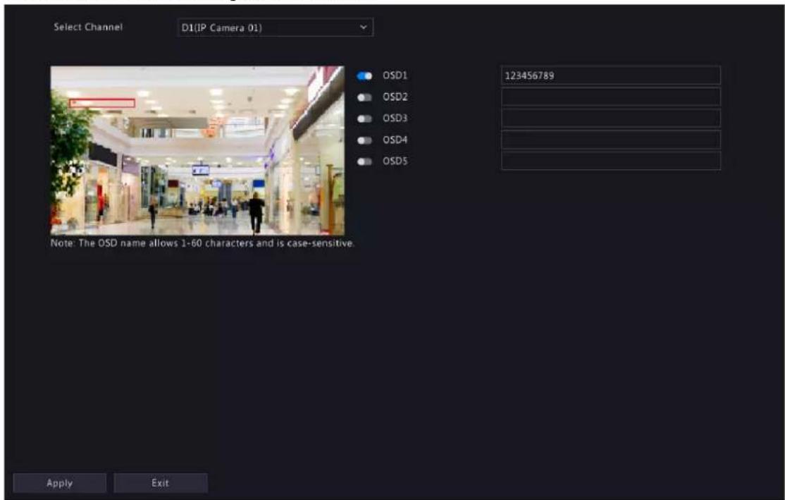
4.3.2 OSD Content
Configure other characters overlaid on the preview (live view) window.
- Go to Menu > Camera > Configuration > Content.
-
Select a channel.
-
Enable OSD(s), and configure OSD name.
Note:
- The number of OSDs may vary with IPC model.
-
The OSD name allows 60 characters and is case-sensitive.
-
Click Apply
-
(Optional) To adjust the font size and color, go to OSD Configuration.
4.3.3 Image Settings
Adjust image settings to get optimal images.
- Go to Menu > Camera > Configuration > Image.

-
Select the desired channel.
-
Select the image scene you want to use.
The IP camera provides several predefined scene modes for different application scenarios. When you select a scene, the parameters will be automatically set, you can also adjust the parameters as needed.
- Indoor: Recommended for indoor scenes.
• Common: Recommended for outdoor scenes.
• Starlight: Recommended for low light conditions.
• Test: Recommended for test scenes.
- Road Highlight Compensation/Park Highlight Compensation: Recommended for capturing vehicle license plates on roads or in parks.
- WDR: Recommended for scenes with high-contrast lighting, such as window, corridor, front door or other scenes that are bright outside but dim inside.
- Custom: Set a scene as needed.
- Configure the parameters under the tabs in this page.

Note:
- Only certain IPCs support scene selection, and the image parameters may vary with IPC model.
- The default settings are scene-adaptive. Use default settings unless modification is necessary. To restore default settings under all the tabs, click Default in the lower left corner. This function is available only when the camera is connected to the NVR via the private protocol.
• Image settings apply to both live and recorded videos.
Image Enhancement
Click the Image Enhancement tab, and set the parameters.
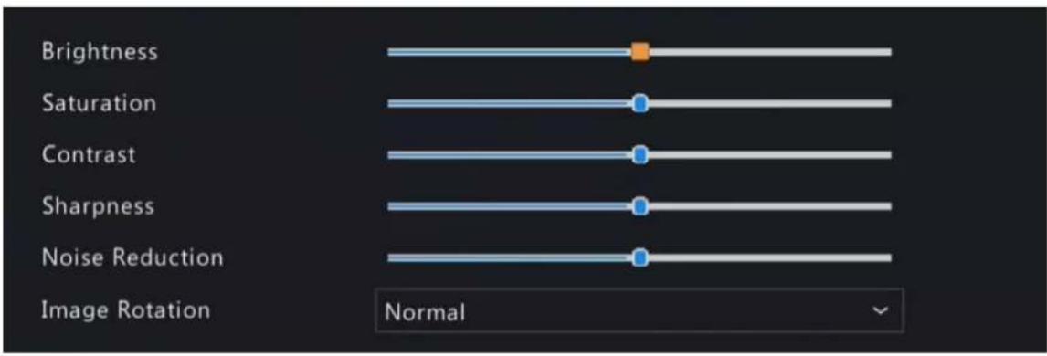
| Item Description | |
| Brightness The overall lightness or darkness of the image. | |
| Saturation The intensity or vividness of colors in the image. | |
| Contrast The difference between the lightest and darkest tones in the image. | |
| Sharpness The contrast between the edges of an object in the image. | |
| Noise Reduction Reduce noises in images, while it may cause image blur or smearing. | |
| Image Rotation The rotation of the image.Normal: Displays images without rotation.Flip Horizontal: Displays images flipped horizontally.Flip Vertical: Displays images flipped vertically.180°: Displays images flipped vertically and horizontally.90° CW: Displays images in corridor format. The camera must be installed correctly (rotated 90° clockwise).90° CCW: Displays images in corridor format. The camera must be installed correctly (rotated 90° counterclockwise). | |
| Splice Distance Adjust splice distance to display splicing image for the dual-lens camera with single channel. The larger the distance, the more natural the splicing effect, thus avoiding video stuttering or image ghosting. The NVR can obtain the current splice distance automatically. Drag the slider to set it as needed.Note:This item appears only for dual-lens cameras that support this function.Configure the splice distance for the dual-lens camera according to the installation scene so as to achieve the best splicing effect. | |
Exposure
Click the Exposure tab, and set the parameters.

| Item Description | |
| Exposure Mode Select the | correct exposure mode to achieve the desired exposure effect.Automatic: The camera automatically sets the exposure parameters according to the scene.Custom: User can set exposure parameters as needed.Shutter Priority: The camera adjusts shutter as priority to adjust the image quality.Indoor 50Hz: Reduce stripes by adjusting the exposure time.Note:Stripe effect: The high-contrast condition in an image caused by uneven light energy received by the sensor.Using this mode in brighter environments aids in adjusting the stripe effect in the image with linear stripe suppression.Indoor 60Hz: Reduce stripes by adjusting the exposure time.Note: Using this mode in brighter environments aids in adjusting the stripe effect in the image with linear stripe suppression.Manual: Fine-tune image quality by setting shutter, gain, and iris manually.Low Motion Blur: Control the minimum shutter to reduce motion blur. |
| Shutter(s) Shutter is used to | control the amount of light that comes into the lens. A fast shutter speed is ideal for scenes in quick motion. A slow shutter speed is ideal for scenes that change slowly.This parameter is configurable when Exposure Mode is set to Manual, Shutter Priority, or Custom.Note: If Slow Shutter is disabled, the reciprocal of the shutter speed must be greater than the frame rate. |
| Gain(dB) Control image signals so that the camera can output standard video signals in different light conditions.This parameter is configurable when Exposure Mode is set to Manual or Custom. | |
| Slow Shutter | Select to enable slow shutter. When enabled, the camera improves image brightness in low light conditions. |
| Slowest Shutter When enabled, you can set the slowest shutter speed for the camera during exposure. | |
| Compensation Adjust the compensation value as required to achieve the desired image effect. | |
| Day/Night Mode • Automatic: The camera automatically switches between night mode and day mode according to the ambient lighting condition to output optimum images.Day: The camera outputs high-quality images in daylight conditions.Night: The camera outputs high-quality images in low light conditions. | |
| Day/Night Sensitivity Light threshold for switching between day mode and night mode. Ultra-low, low, medium, and high are available. A higher sensitivity level means that the camera is more sensitive to the change of light and is therefore more easily to switch between day mode and night mode.This parameter is configurable when Day/Night Mode is set to Automatic. | |
| Day/Night Switching(s) Set the length of time before the camera switches between day mode and night mode after the switching conditions are met.This parameter is configurable when Day/Night Mode is set to Automatic. | |
| WDR Suitable for high-contract scenes. WDR can balance the brightness in the bright area and dark area, and provide clear image with more details.On/Off: User needs to identify WDR scenes, and manually enable or disable WDR as needed.Smart (Automatic): The device can automatically identify typical WDR scenes, and then enable or disable WDR.Note: When WDR is enabled, some other functions may not be supported. Refer to the actual interface for details. | |
| WDR Level Adjust the WDR level to improve image quality when WDR is enabled.Note: In the case of low contrast, it is recommended to disable WDR or use level 1 to 6. Level 7 or higher is recommended if there is a high contrast between the bright and dark areas in the scene. | |
| WDR On/Off Sensitivity When WDR is set to Automatic, adjust the parameter to change the WDR switching sensitivity. | |
| Metering Control Perform luminance statistics on the images captured by the device, automatically adjust the exposure value, and output properly exposed images with optimal brightness. The default is the Center-Weighted Average Metering, you may configure this according to the actual scene.Center-Weighted Average Metering: Measure light mainly in the central part of the image.Evaluative Metering: Measure light in the specified area of the image,Face Metering: Adjust image quality in poor lighting or back lighting conditions by controlling the brightness of captured faces in face scenes.Spot Metering: Similar to the evaluative metering. However, it cannot increase the brightness of the image.Note: This parameter is configurable when Exposure Mode is not set to Manual. | |
| Linear Stripe Suppression Adjust the linear stripes in the image.Range: 1 to 9, the default is 5. The greater the value, the more obvious the linear stripe suppression effect is, but it may cause overexposure in the image. Please configure this according to the actual scene.Note: This parameter is configurable when Exposure Mode is set to Indoor 50Hz or Indoor 60Hz. | |
Smart Illumination
Click the Smart Illumination tab, and set the parameters.
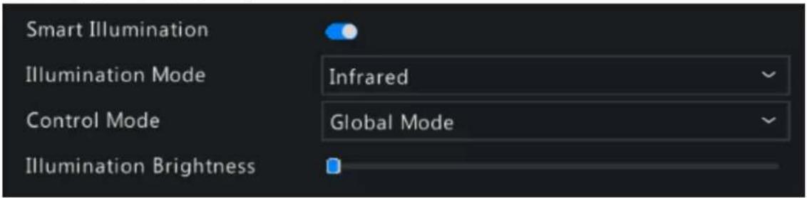
| Item Description | |
| Smart Illumination Enable Smart Illumination. | |
| Illumination Mode Select the illumination mode from the drop-down list.Infrared: The camera uses infrared light illumination.White Light: The camera uses white light illumination.Dual Light: The camera adjusts the white light or infrared automatically according to the current lighting condition. | |
| Control Mode Select the control mode from the drop-down list.Global Mode: The camera automatically adjusts illumination brightness and exposure to achieve the balanced image effect.Overexposure Restrain: The camera automatically adjusts illumination brightness and exposure to avoid regional overexposure.Manual: Control the brightness of illumination manually. | |
| Illumination Level Drag the slider to adjust the illumination level. This parameter is configurable when Control Mode is set to Manual. The greater the value, the higher the intensity (0 is off). | |
White Balance
Click the White Balance tab, and set the parameters.

| Item Description | |
| White Balance Adjust the red | and blue gains of the image to remove unrealistic color casts.·Auto: The camera automatically adjusts the red and blue gains according to the lighting condition (the color tends to be blue).·Fine Tune: Adjust the red or blue offsets manually.·Outdoor: Suitable for outdoor scenes where the color temperature varies widely.·Sodium Lamp: The camera automatically adjusts red and blue gains according to the lighting condition (the color tends to be red).·Locked: Lock the current color temperature to avoid change. |
| Red Offset Adjust the red offset manually. | |
| Blue Offset Adjust the blue offset manually. | |
Advanced Settings
Click the Advanced tab, and set the parameters.

| Item Description |
| Defog Enable/disable defog from the drop-down list. Defog is used to improve image visibility in foggy, hazy and other low-visibility scenes. |
| Defog Intensity When defog is enabled, you can adjust the defog intensity.In a heavy-fog environment, the higher the defog level, the clearer the image. In a fog-free or light-fog environment, there is not much difference between levels 1 to 9.Note: Optical defog is available only for certain IPC models. When the defog intensity is set to 6 or higher, optical defog automatically turns on in thick fog, and images change to black and white. |
4.3.4 Privacy Mask
Privacy mask is used to cover certain areas on the image for privacy, for example, ATM keyboard. When a PTZ camera rotates and zooms, the privacy mask moves and zooms with the camera and the masked area is always covered.
- Go to Menu > Camera > Configuration > Privacy Mask.
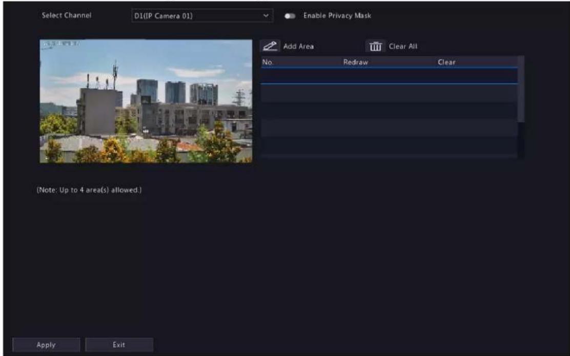
- Select the desired channel from the drop-down list.
- Enable privacy mask.
- Click and then use the mouse to specify a rectangle area on the left-side image. The number of areas supported varies with NVR model. Some NVRs support 4 areas and some support 8 areas.

- Adjust the size and position of the mask: Point to a handle of the mask and drag to resize it. Point to any position of the mask and drag it to the desired position.
- Redraw: Click to clear all the existing area(s) and draw an area again.
- Delete: Select the mask and click for click to delete all the masks.
5. Click Apply.
4.4 PTZ Configuration
Configure and control PTZ cameras.

Note:
- This function is only available for PTZ cameras.
- The PTZ parameters may vary with IPC model.
- PTZ (pan, tilt and zoom) control is applicable to PTZ cameras only and may vary depending on the functions and protocols supported by the PTZ cameras. Refer to PTZ camera specifications for details.
PTZ Control Mode
DVRs support two control modes, including Coaxial or Serial Port. Choose the control mode before using PTZ function.
- Go to Menu > Camera > PTZ.
- Choose a control mode according to camera connection method, and complete other settings.
Configure PTZ
Option 1: Enter Menu
- Go to Menu > Camera > PTZ.
- Select the target PTZ camera.

- Set the parameters. See below for details.
Option 2: Use PTZ Toolbar
- On the preview page, select the target window, click on the window toolbar.

- The PTZ control window appears. You can control the PTZ camera as needed.
- Click PTZ Configuration, and set the parameters.

Table 4-2: PTZ Control Window Buttons
| Button Description | |
 | Control the rotation direction of the PTZ camera; release PTZ control. |
 | Zoom in or out on images.Note: You can also zoom in or out using the scroll wheel on your mouse.Focus far or near for clear images.Increase or reduce the amount of light that enters the lens of the camera. |
 | Control the rotation speed of the camera. 1-9 are available. 1 means the slowest, and 9 means the fastest. |
 | Click to display the PTZ Configuration page. |
 | Turn on/off the light.Turn on/off the wiper.Turn on 3D positioning.Turn on/off the heater.Turn on/off the snow removal.Turn on/off PTZ shortcut operations.Note:Make sure that the 3D positioning, heater and snow removal functions are supported by the camera before using.Use 3D positioning to zoom in or out. Dragging from top down zooms in. Dragging the other way zooms out. |
Preset/ Preset Patrol/Recorded Patrol/ Auto Guard | For detailed information, see Preset, Preset Patrol, Recorded Patrol and Auto Guard respectively.Call a preset: Click, the PTZ camera goes to the preset position.Delete a preset: Click, the delete the preset.Note: and are displayed for saved presets only. |
| Start or stop preset patrol. |
OSD Menu
Configure analog cameras on DVRs. This function is only available for DVRs.
- In the preview window of an analog camera, click on the window toolbar.
- Click OSD Menu.
- Click or to open camera settings window, and set the parameters.
- Click to save the settings, and then choose Exit button to close the window.
Preset
A preset position (preset for short) is a saved view used to quickly steer the PTZ camera to a specific position.
- Add a Preset
- Use the PTZ direction buttons to steer the PTZ camera to the desired position.
- Select a preset number not in use, and click to edit the preset name.

- Click OK to save. Repeat the above steps to add all the presets.
| No. | Preset Name | Edit | Call | Delete |
| 001 | Preset001 | |||
| 002 | Preset002 | - | - | |
| 003 | Preset003 | - | - | |
| 004 | Preset004 | - | - |
- Call a Preset
In the preset list, select the preset to call and click. Then the camera rotates to the preset position.
- Delete a Preset
In the preset list, select the preset to delete, and then click
Preset Patrol
Set a preset patrol route so the PTZ camera can patrol by presets (go from one preset to the next in the specified order).
- Add Preset Route
- Click Preset Patrol, and select a patrol route.

- Click The figure as shown below appears.
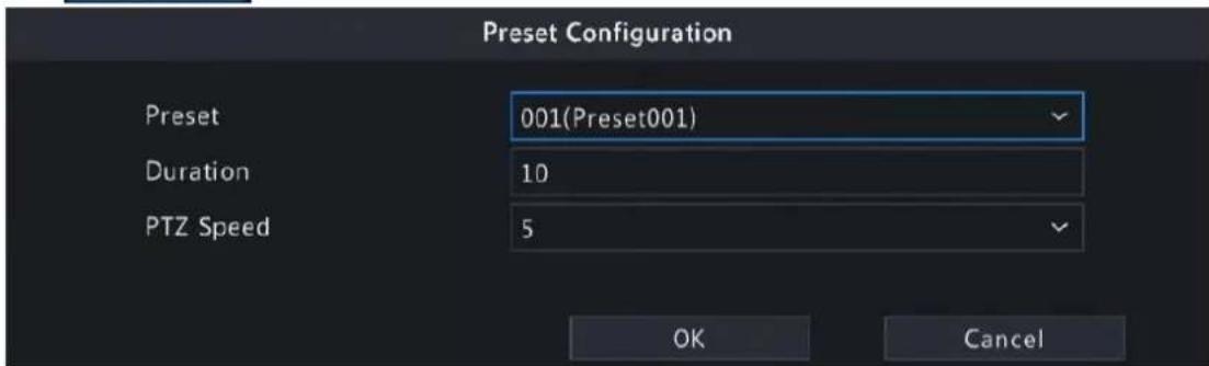
- Complete the parameters, and click OK.
| Item Description |
| Preset Set the length of time the camera stays at the preset after performing the patrol. See Preset for setting preset. |
| Duration(s) Set the time the camera stays at the preset after the patrol is performed. The valid range is from 120 to 1800 seconds. The default is 10s. |
| Speed Set the rotation speed. 1 means the slowest, 9 means the fastest. The default is 5. |
- Repeat the above steps to add more routes.
Note: Up to 4 patrol routes are allowed for each PTZ camera. Up to 8 presets (keypoints) are allowed for each patrol route.
- Call a Preset
Select a preset patrol in the list, click to start the preset patrol. To stop, click .


- Other Operations
• Edit: Click edit the preset patrol parameters.
- Delete: Click to delete a keypoint; Click to delete all keypoints.
- Move Up/Move Down: Click /to adjust the sequence of these presets.
Recorded Patrol
Record a patrol route so the PTZ camera can patrol according to the recorded patrol.
- Add a Recorded Patrol
- On the Recorded Patrol tab, select a patrol route.
- Click to start recording. Steer the camera to the desired direction, adjust the zoom, focus, iris as needed during the process.

-
Click to stop recording.
-
Click Apply.
- Call a Recorded Patrol
Click to start the recorded patrol. Click to stop the recorded patrol.
Auto Guard
Configure auto guard so the PTZ camera automatically performs the specified action (e.g., going to a preset or starting a patrol) after being idle (no user operation) for a certain length of time.

Note: Before use, you need to add a preset or a patrol route.
- On the Auto Guard tab, select the Enable check box to enable auto guard.
- Set the parameters.
| Item Description | |
| Idle State(s) Set the idle duration for the camera to start auto guard. 1 to 3600 seconds are available. The default is 60s. | |
| Mode Select preset or patrol route. | |
| Preset/Patrol Select a preset number or patrol route number. | |
- Click Apply.
4.5 Panoramic Linkage
Configure panoramic linkage for cameras that support the function.
Enable Panoramic Linkage
- Go to Menu > Camera > Panoramic Linkage.
- Select the camera that supports panoramic linkage.

3. Enable Panoramic Linkage.
Configure Panoramic Linkage
| Parameter Description | |
| Auto Calibration Calibrate in close-up image | and panoramic image to ensure accurate panoramic linkage.1. ClickAuto Calibration, and then manually calibrate the center of panoramic image and close-up image.2. ClickNextto complete the calibration. |
| Manual Calibration After completing auto calibration, you can manually adjust the coordinate.1. Click any coordinate from the list, the close-up image will move to the corresponding coordinate.2. Adjust the coordinate image by using the PTZ control panel.3. Clickto save the calibration. | |
 | Control the rotation direction of the PTZ camera; release PTZ control. |
 | Zoom in or out on images.Note: You can also zoom in or out using the scroll wheel on your mouse.Focus far or near for clear images.Increase or reduce the amount of light that enters the lens of the camera. |
 | Control the rotation speed of the camera. 1-9 are available. 1 means the slowest, and 9 means the fastest. |
4.6 Radar Configuration
Add, modify, or delete radar devices on the NVR.

Note:
- Up to 20 radar devices are allowed.
- NVR can receive realtime people counting data from the radar devices, and then transfer the data to UCS if connected to the cloud. However, it does not store and search data.
Add Radar
- Go to Menu > Camera > Radar.

- Click Add Radar, and then configure radar parameters.
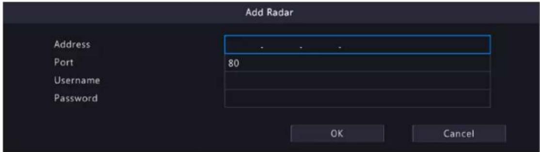
| Parameter Description | |
| Address IP address of the radar device. | |
| Port 80 by default. | |
| Username Username used to log in to | the radar device. |
| Password Password used to log in to | the radar device. |
- Click OK.
Modify Radar
Click to modify the radar information.

Delete Radar
You can delete radar device(s) one by one or in batches.
• Delete one by one: Select a radar device to be deleted, and then click

- Delete in batches: Select radar devices to be deleted, click Delete Radar, and then click OK.
Refresh
Click Refresh to show the latest radar list.
5 Search
Search recordings and snapshots based on event and object, and people counting data, and support backup.

Note: The search and backup functions may vary with device models.
5.1 Recording Backup
Recording backup refers to backing up videos stored on the NVR's hard disk to a USB storage device. It has the following conditions:
- The USB storage device has been formatted to FAT32 or NTFS.
- Backup permission is required.
- The recording to back up is stored on a hard disk of the NVR.
- The storage device is connected correctly to the NVR.

Note:
- Recordings are backed up as .mp4 files by default.
- You can back up recordings in HD or SD mode.
Normal Video Backup
Normal video backup refers to backing up scheduled recording, manual recording, and event-triggered recording.
- Go to Menu > Search > Video > Recording.
- Select the desired camera(s). All cameras are selected by default.

- Set search conditions, including the start time, end time, recording type, event type, VCA type, file type, and clarity (HD or SD).
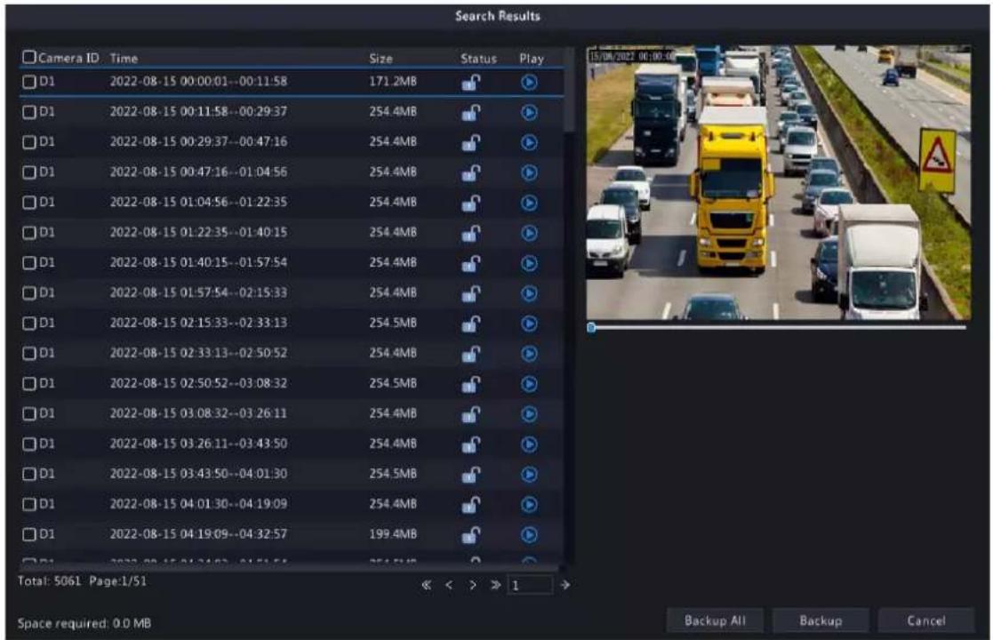
- Click Search. Search results are displayed. The image from the first search result is displayed on the right side.
Click to play the video.
-
Choose a way to back up recording(s) as needed.
-
Select the recording(s) you want to back up, and then click Backup.
- Or click Backup All to back up all the recordings in the list.

- Select the partition and storage path, and then click Backup. You can also create a new folder for the recording(s) by clicking New Folder.

Note:
- Click Format to format the USB device. A USB device with more than 2TB capacity can only be formatted to NTFS, with 2TB or less capacity can be formatted to NTFS or FAT32. Only certain NVRs can format a USB device with more than 2TB capacity.
- During backup, a progress bar is displayed to indicate the progress (e.g., Exporting X/Y), where X indicates the current number being backed up, and Y indicates the total number of recordings. To stop the backup, click Cancel.
- A backup file is named in this format: Camera ID_S recording start time_E recording end time.file extension. For example, D1-S20220823000400_E20220823003148.mp4, where S means the start time, and E means the end time.
Video Clip Backup
Video clip backup refers to clipping a recording and saving it to a USB storage device.
- Right-click and select Playback to go to the Playback page.

- Click to select HD or SD on the playback toolbar. The default is HD.
- Select the desired camera to play the recorded video. Click to clip the video during the playback. Click

to save the video clip.
- Click to view the video clip on the Video Clip tab.

- Select the desired video clip(s) and then click Backup.
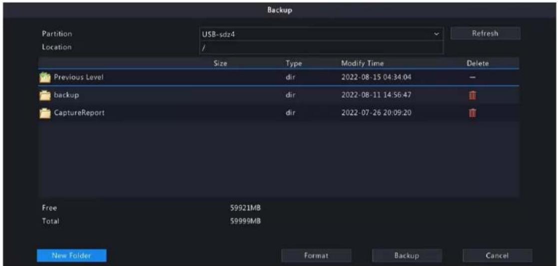
- Select the partition and storage path, click Backup. Then the recordings are saved to the specified path on the storage device. You can also create a new folder for the recording(s) by clicking New Folder.
5.2 Image Backup
Image backup refers to backing up images stored on the NVR's hard disk to a USB storage device.

Note: The default format of image backup is *.JPG.
Normal Snapshot Backup
Normal snapshot backup refers to backing up scheduled snapshot, manual snapshot, and event-triggered snapshot.
- Go to Menu > Search > Picture > Snapshot Backup.

- Select the desired camera(s). All cameras are selected by default.
- Set search conditions, including the image type, start time, and end time.
- Click Search. Search results are displayed. The image displayed on the right is from the first result in the list by default.


Note: The image resolution depends on the resolution from the output interface and the number of windows displayed when the snapshot is taken.
- Choose a way to back up image(s) as needed.
- Select the desired image(s) you want to back up, and then click Backup.
- Or click Backup All to back up all the images in the list.
- Select the partition and storage path, click Backup. Then the images are backed up to the specified path on the storage device. You can also create a new folder for the image(s) by clicking New Folder.
Playback Snapshot Backup
Playback snapshot backup refers to backing up snapshots that are taken during playback to a USB storage device.
- Go to the Playback page.

- Click to select HD or SD on the playback toolbar. The default is HD.
- Select the desired camera to play the recorded video. Click to take a snapshot during the playback.
- To view the saved snapshot(s), click
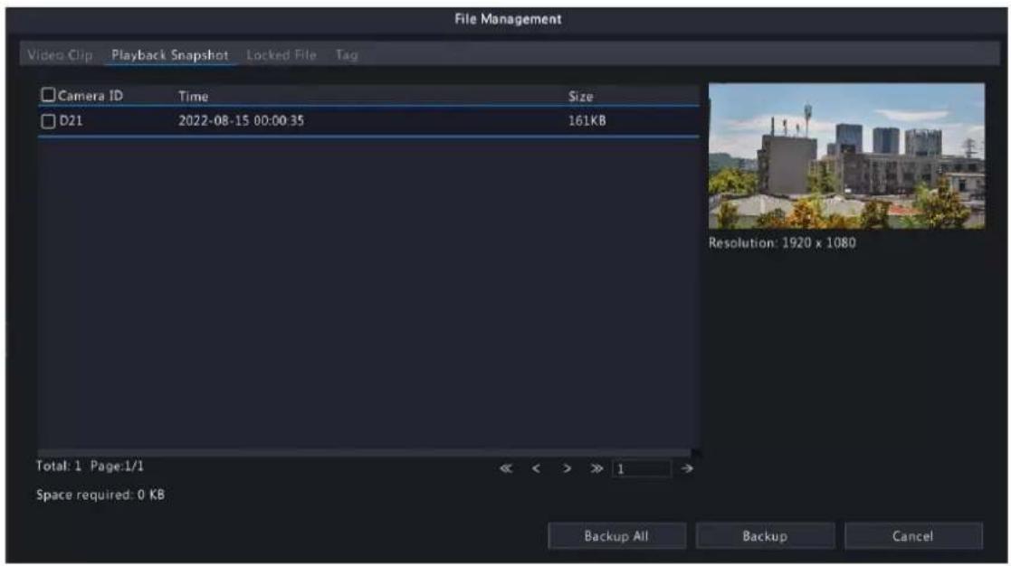
- Select the desired snapshot(s) and then click Backup.

- Select the partition and storage path, and then click Backup. The snapshots are saved in the specified path on the storage device. You can also create a new folder for the snapshot(s) by clicking New Folder.
5.3 Event
Smart Event
Back up images and recordings triggered by smart event alarms.
- Go to Menu > Search > Event > Event Search.
- Set search conditions.
| Parameter Description | |
| Select Channel Select the channel(s) to search. | |
| Start/End Time Specify the time period to search. | Note: A search range smaller than five months is recommended, because earlier snapshots and recordings may have been overwritten due to full storage. |
| Event Type Select Smart Event. | |
| Smart Event Type | Select the smart event type: All, Cross Line Detection, Intrusion Detection, Enter Area, Leave Area, and Ultra Motion Detection. |
- Click Search. The search results are shown in tile mode by default. You may click to switch to list mode.
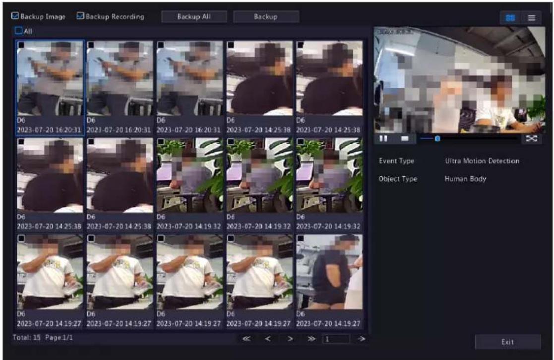
- By default, a 10s video (5s before and 5s after the first image) and the detailed information about the first image are displayed on the right.
- You can click any image to view the 10s video and detailed information about it.
-
Double-click an image on the left to magnify it; double-click the recording on the right to play it in full screen. See search results of Motor Vehicle Search for details.
-
Select Backup or Backup All. See for details.
Basic Event
Back up images and recordings triggered by basic event alarms.
- Go to Menu > Search > Event > Event Search.
- Set search conditions.
| Parameter Description | |
| Select Channel Select the channel(s) to search. | |
| Start/End Time Specify | the time period to search.Note:A search range smaller than five months is recommended, because earlier snapshots and recordings may have been overwritten due to full storage. |
| Event Type Select Basic | Event. |
| Basic Event Type | Select the basic event type:All, Motion Detection, Video Loss, Audio Detection, People Present Alarm, Human Body Detection, Doorbell Call, People Present Minor Alarm, People Present Major Alarm, and People Present Critical Alarm. |
- Click Search.
• The search results are shown in tile mode by default. You may click to switch to list mode.

- The image from the first search result is displayed on the right side. Click to play the video.
- Back up search results. See Back up search results for details.
5.4 Object
Search for images based on various objects, including person, motor vehicle, and non-motor vehicle.
5.4.1 Person Search
Search for images based on human body events, face snapshots and face comparison results.
5.4.1.1 Human Body Search
Search for images based on human body events.
- Go to Menu > Search > Object > Person > Human Body Search.

- Set search conditions.
| Parameter Description | |
| Select Channel Select the channel(s) to search. | |
| Event Type | Select the event type: All, Cross Line Detection, Intrusion Detection, Enter Area, Leave Area, Mixed-Traffic Detection, Traffic Monitoring, Ultra Motion Detection, etc. |
| Start/End Time Specify | the time period to search.Note:A search range smaller than five months is recommended, because earlier snapshots and recordings may have been overwritten due to full storage. |
| Gender | Select the gender: All, Male, or Female. |
| Age | Select the age: All, Childhood, Teenager, Youth, Middle Age, or Senior. |
| Mask | Select the mask: All, No Mask, or With Mask. |
| Hairstyle | Select the hairstyle: All, Long Hair, or Short Hair. |
| Bag | Select the bag: All, No Bag, Handbag, or Backpack. |
| Direction | Select the direction: All, Motionless, Upward, Downward, Leftward, Rightward, Top Left, Bottom Left, Top Right, or Bottom Right. |
| Upper Garment Length | Select the upper garment length: All, Short Sleeve, or Long Sleeve. |
| Lower Garment Length | Select the lower garment length: All, Shorts, or Trousers. |
-
Click Search. The search results are shown in tile mode by default. You may click to switch to list mode.
-
By default, a 10s video (5s before and 5s after the first image) and the detailed information about the first image are displayed on the right.
- You can click any image to view the 10s video and detailed information about it.
- Double-click an image on the left to magnify it; double-click the recording on the right to play it in full screen.
-
You can click All Attributes to view detailed human body attributes.
-
Back up search results. See Back up search results for details.
5.4.1.2 Face Snapshot Search
Search for face snapshots.
Search Face Snapshots
- Go to Menu > Search > Object > Person > Face Snapshot Search.
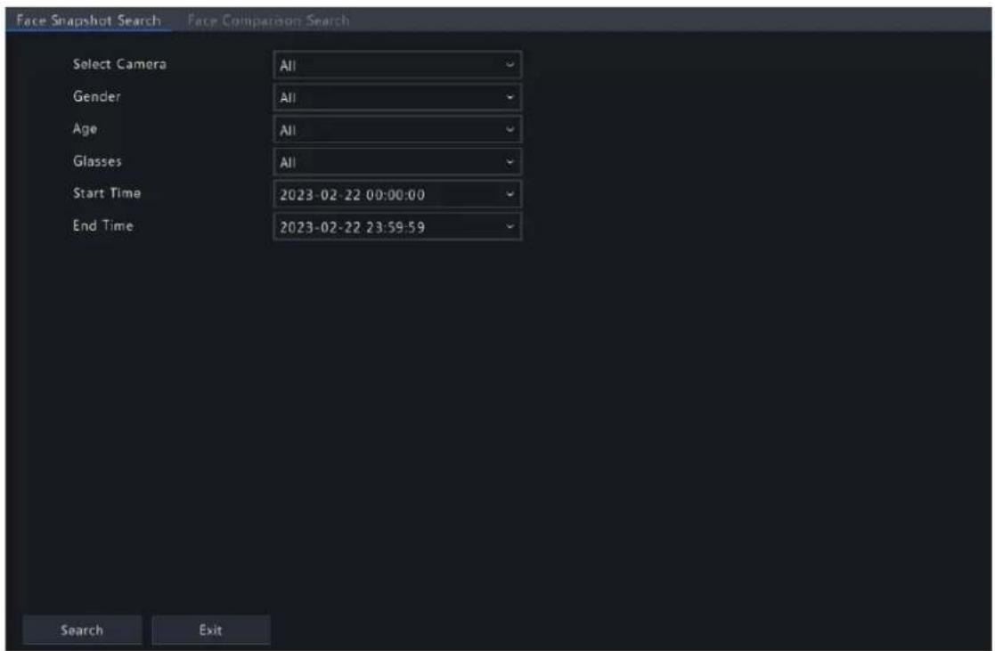
- Set search conditions.
| Parameter Description | |
| Select Camera Select the camera(s) to search. | |
| Gender | Select the gender: All, Male or Female. |
| Age | Select the age: All, Childhood, Teenager, Youth, Middle Age, or Senior. |
| Glasses | Select the glasses status: All, No Glasses, or With Glasses. |
| Start/End Time Specify the time period to search for face snapshots.Note:A search range smaller than five months is recommended, because earlier snapshots and recordings may have been overwritten due to full storage. | |
- Click Search. The search results are shown in tile mode by default. You may click ≡ to switch to list mode.
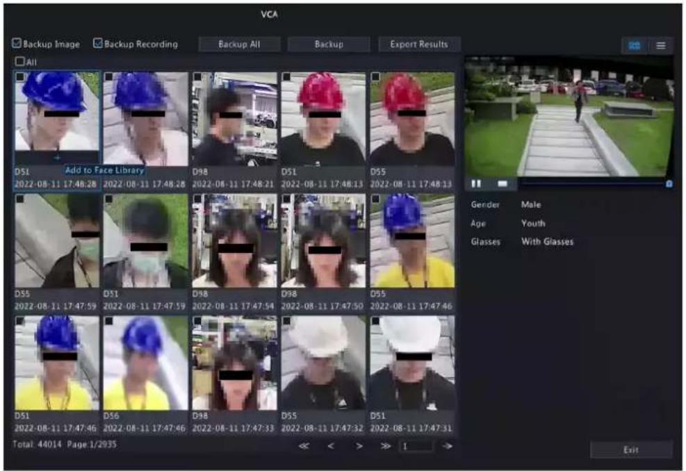

Note:
- By default, a 10s video (5s before and 5s after the first image) and the detailed information about the first image are displayed on the right.
- You can click any image to view the 10s video and detailed information about it.
- Double-click an image on the left to magnify it; double-click the recording on the right to play it in full screen.
List : ≡

- By default, a 10s video (5s before and 5s after the first item) and the detailed information about the first item are displayed on the right.
• You can click any item and click to view the 10s video and detailed information about it.
Other Operations
| Operation Description | |
| Backup/Backup All | 1. Enable Backup Image or/and Backup Recording as needed. By default, they are both enabled.Backup Image: Back up the selected image(s) to an external device.Backup Recording: Back up the 10s video of the selected image(s) to an external device.2. Select Backup or Backup All.Backup: Back up specified search results. Select the search result(s) you want to back up and click Backup.Backup All: Back up all search results. Click Backup All. |
| Export Results | Enable Backup Image or/and Backup Recording as needed, and click Export Results.2. Select the export partition and click Export Results to export the search results to an external storage device. |
5.4.1.3 Face Comparison Search
Search for face comparison results.
- Go to Menu > Search > Object > Person > Face Comparison Search.

- Set search conditions.
| Parameter Description | |
| Select Camera Select the camera(s) to search. | |
| Alarm Type | Select the alarm type:Face MatchorFace Not Match. |
| Name Enter the name you want to search. | |
| Matching Range(%) The similarity between the captured faces and the face images in face lists, ranging from 1% to 100%. The higher the similarity, the more accurate the face comparison. Set it as needed. | |
| ID No. Enter the ID number you want to search. | |
| Start/End Time Specify the time period to search for face snapshots.Note:A search range smaller than five months is recommended, because earlier snapshots and recordings may have been overwritten due to full storage. | |
- Click Search. The search results are shown in tile mode by default. You may click ≡ to switch to list mode.

Tile


Note:
- By default, a 10s video (5s before and 5s after the first image) and the detailed information about the first image are displayed on the right.
- You can click any image to view the 10s video and detailed information about it.
• List


- By default, a 10s video (5s before and 5s after the first item) and the detailed information about the first item are displayed on the right.
-
You can click any item and click to view the 10s video and detailed information about it.
-
Back up search results.
(1) Enable Backup Image or/and Backup Recording as needed. By default, they are both enabled.
- Backup Image: Back up the selected image(s) to an external device.
- Backup Recording: Back up the 10s video of the selected image(s) to an external device.
(2) Select Backup or Backup All.
- Backup: Back up specified search results. Select the search result(s) you want to back up and click Backup.
- Backup All: Back up all search results. Click Backup All.
5.4.2 Motor Vehicle Search
Search for images based on motor vehicle monitoring events.
- Go to Menu > Search > Object > Motor Vehicle > Motor Vehicle Search.

- Set search conditions.
| Parameter Description | |
| Select Camera Select the camera(s) to search. | |
| Event Type | Select the event type: All, Cross Line Detection, Intrusion Detection, Enter Area, Leave Area, Mixed-Traffic Detection, Traffic Monitoring, Ultra Motion Detection or Plate Comparison, etc. |
| Start/End Time Specify the time period to search.Note:A search range smaller than five months is recommended, because earlier snapshots and recordings may have been overwritten due to full storage. | |
| Vehicle Type Select the vehicle type to search. | |
| Plate Type Select the plate type to search. | |
| Vehicle Color Select the vehicle color to search. | |
| Plate Color Select the plate color to search. | |
| Vehicle Brand | Select the vehicle brand: All, Large Vehicle Plate, Small Vehicle Plate, Embassy Vehicle Plate, Consulate Vehicle Plate, Trailer Plate, Coach Vehicle Plate, Police Vehicle Plate, Police Motorcycle Plate, Border Crossing Vehicle Plate (Hong Kong), WJ License Plate, Military Plate, or Small New Energy Vehicle, etc. |
| Plate No. Enter the plate number to search. | |
| Direction | Select the direction: All, Motionless, Upward, Downward, Leftward, Rightward, Top Left, Bottom Left, Top Right or Bottom Right. |
| Plate Comparison | Select the plate comparison type: All, Match, or Not Match. |
Parameter Description

Note: This parameter appears when Event Type is Plate Comparison.
- Click Search. The search results are shown in tile mode by default. You may click to switch to list mode.

- By default, a 10s video (5s before and 5s after the first image) and the detailed information about the first image are displayed on the right.
- You can click any image to view the 10s video and detailed information about it.
-
Double-click an image on the left to magnify it; double-click the recording on the right to play it in full screen.
• You can click All Attributes to view detailed motor vehicle attributes. -
Back up search results. See Back up search results for details.
-
To export the search results as a .CSV file, click Export Results.
| 1 | No. | Camera ID | Camera Name | Time | Plate No. | Plate Color | Vehicle Color |
| 2 | 1 | D1 | D18Plate22247 | 2022-08-05 10:02:59 | 1545666 | Blue | Other |
| 3 | 2 | D2 | D19Plate2 | 2022-08-05 16:02:40 | TT45413 | Blue | White |
| 4 | 3 | D3 | D20Plate22249 | 2022-08-05 16:00:39 | AA435403 | Green | White |
| 5 | 4 | D4 | D21Plate22250 | 2022-08-05 15:58:13 | B4G5404 | Blue | Black |
| 6 | |||||||
| 7 | |||||||
| 8 | |||||||
| 9 | |||||||
| 10 | |||||||
| 11 | - | ||||||
| 12 | |||||||
| 13 | |||||||
| 14 | |||||||
| 15 | |||||||
| 16 | |||||||
| 17 |
5.4.3 Non-Motor Vehicle Search
Search for images based on non-motor vehicle events.
- Go to Menu > Search > Object > Non-Motor Vehicle > Non-Motor Vehicle Search.

- Set search conditions.
| Parameter Description | |
| Select Camera Select the camera(s) to search. | |
| Event Type | Select the event type: All, Cross Line Detection, Intrusion Detection, Enter Area, Leave Area, Mixed-Traffic Detection, Traffic Monitoring or Ultra Motion Detection or Plate Comparison, etc. |
| Start/End Time Specify | the time period to search.Note:A search range smaller than five months is recommended, because earlier snapshots and recordings may have been overwritten due to full storage. |
| Non-Motor Vehicle Type | Select the non-motor vehicle type: All, Bicycle, 3-wheel Vehicle, Motorcycle, Electric Moped or 2-wheel Vehicle. |
| Direction | Select the direction: All, Motionless, Upward, Downward, Leftward, Rightward, Top Left, Bottom Left, Top Right or Bottom Right. |
| Gender | Select the gender: All, Male or Female. |
| Age | Select the age: All, Childhood, Teenager, Youth, Middle Age, or Senior. |
| Upper Garment Length | Select the upper garment length worn by drivers: All, Short Sleeve or Long Sleeve. |
-
Click Search. The search results are shown in tile mode by default. You may click ≡ to switch to list mode.
-
By default, a 10s video (5s before and 5s after the first image) and the detailed information about the first image are displayed on the right.
- You can click any image to view the 10s video and detailed information about it.
- Double-click an image on the left to magnify it; double-click the recording on the right to play it in full screen.
-
You can click All Attributes to view detailed non-motor vehicle attributes (human body attributes will be shown when event type is mixed-traffic Detection).
-
Select Backup or Backup All. See Backup or Backup All for details.
5.5 Statistics
5.5.1 People Counting Report
Search for people counting data. You can view daily/weekly/monthly/yearly people counting reports, the number of people entering and/or leaving a certain area or scene during a specified time period.
- Go to Menu > Search > Statistics > People Counting Report.

- Set search conditions.
| Parameter Description | |
| Counting Type Count people flow data according to the camera or scene. | |
| Select Camera/Scene Select • Camera: Select the camera(s) to search.• Scene: Select the scene to search. Please configure scene information first, see People Present Alarm for details. | |
| Counting Type | Select the counting type to search: Total, People Entered, or People Exited. |
| Report Type | Select the report type to view: Hourly, Daily, Weekly, Monthly, or Yearly. |
| Statistical Time Select the time to count. | |
- Select to create the report as a chart or a table.
- Chart
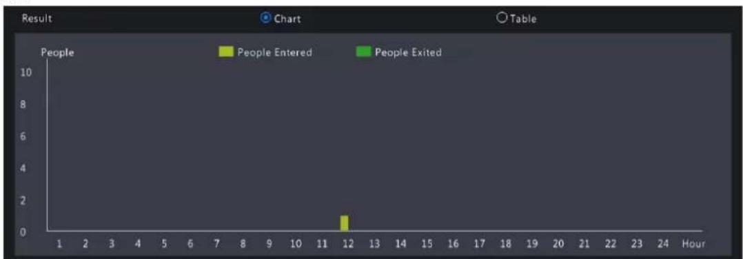
other
| Hour | People Entered | People Exited | | ---- | --------------- | -------------- | | 1 | 0 | 0 | | 12 | 1 | 0 |- Table

- Click Backup to export the report to an external storage device as a .CSV file. The content of the file exported from a report in chart or table format is the same. Take the exported results of daily report as an example:
| Camera ID | Camera Name | Statistical Time | People Entered | People Exited |
| D4 | N5 | 11:00-12:00 | 12 | 11 |
| D4 | N5 | 12:00-13:00 | 15 | 7 |
| D4 | N5 | 13:00-14:00 | 4 | 4 |
| D4 | N5 | 14:00-15:00 | 7 | 2 |
5.5.2 Heat Map
The heat map function is used with a fisheye camera to monitor people counting in supermarkets or shops. You can view the heat map formed by the people flow statistics of a specified channel during a specified time period, which can help you plan accordingly, and improve service, operational efficiency and profitability.
- Go to Menu > Search > Statistics > Heat Map.

- Set search conditions.
| Parameter Description | |
| Select Channel Select the channel to count heat data. | |
| Report Type | Select the report type to view: Daily, Weekly, Monthly, or Yearly. |
| Statistical Time Select a statistical period. | |
- Click Count to view the result.

- Click Export to export the heat map image to an external storage device as a .jpg file. The exported file is an image, regardless of the report type. Take the exported result of daily report as an example:
Heat Map_Ch3_2023 0525.jpg
6 VCA
Configure VCA (Video Content Analysis), analyzer, and VCA search.
6.1 VCA Configuration
VCA includes face recognition, perimeter protection, temperature detection, mixed-traffic detection, exception detection & statistics, and people counting. You can monitor people flow, roads and moving objects by configuring VCA. The VCA functions and parameters may vary with NVR model.

Note: VCA functions are not available if there is no disk in slot 1.
- Go to Menu > VCA > VCA Config.

-
Select a camera.
-
Select the check box of the VCA function to be enabled, and choose whether to implement this function on the camera side or the NVR side.
-
Camera Side Analysis: The VCA function is implemented by the camera.
- NVR Side Analysis: The VCA function is implemented by the NVR.
Note:
- The parameters of some VCA functions supported on the camera side are more than that supported on the NVR side.
- Before you enable camera side analysis, make sure the camera is connected via private protocol.
• VCA functions that are not supported by the camera or NVR are grayed out. -
VCA functions on the NVR side is subject to device capabilities. For more information, go to Menu > VCA > Analyzer Config.
-
Click to configure the function.
6.1.1 Face Recognition
Face recognition includes face detection and face comparison.
Face detection detects and captures faces in a specified detection area.

Note: The functions and parameters supported by camera side analysis and NVR side analysis are different.
- Go to Menu > VCA > VCA Config.
- Select a camera.
- Select Face Detection and click to configure it.

- Set the detection area. Only 1 detection area is allowed.
• Full Screen: Detects all faces in the live video.
- Specify Area: Detects faces in a specified area of the live video. Select Specify Area, click 📄, then the full screen will be displayed and a default detection box appears. You can adjust the position of the area or draw an area as needed. Right-click to exit the full screen.
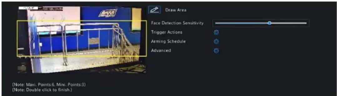
- Adjust the position of the area. Point to a border of the area and drag it to the desired position.
-
Draw an area. Click on the image and drag to draw a line. Repeat the action to draw more lines to form an enclosed shape as needed. Up to 6 lines are allowed.
-
Set the face detection sensitivity by dragging the slider. The higher the sensitivity, the more likely a face will be detected. The lower the sensitivity, the less likely a side face or blurring face will be detected.
- Set the alarm-triggered actions and arming schedule. See Alarm-triggered Actions and Arming Schedule for details.
- Click right to Advanced, configure the parameters as needed, and then click OK.

On certain NVRs, the Advanced page shows as follows:

| Parameter Description | |
| Min. Pupillary Distance(px) The minimum distance (measured in pixels) between two pupils. Faces with pupillary distance smaller than the value will not be captured.Note: The default value varies by image resolution, and the valid range varies by NVR model. | |
| Number of Snapshots The number of snapshots to be captured when the detection rule is triggered. Range: 1 to 30. Default: 5. | |
| Enable Face Selection Select whether to select face snapshots to report. | |
| Face Selection Mode | Effect Priority: Set the Number of Selected Photos, then the NVR selects the specified number of snapshots with the best quality from all the snapshots captured when a face is detected to report.Speed Priority: Set the Number of Selected Photos and Selection Timeout, then the NVR selects the specified number of snapshots from the moment that a face is detected till Selection Timeout is up to report. Range: 1 to 1800. Periodic Selection: Set the Selection Timeout, for example, 600ms, then the NVR selects a face snapshot every 600ms to report. Periodic Selection: Set the Selection Timeout, for example, 600ms, then the NVR selects a face snapshot every 600ms to report. Quick Report: A face snapshot that exceeds the set score will be reported, and a higher quality snapshot will be reported to replace theprevious one. The number of face snapshots is 1 by default and cannot be modified. Quick Report: A face snapshot that exceeds the set score will be reported, and a higher quality snapshot will be reported to replace theprevious one. The number of face snapshots is 1 by default and cannot be modified. Note: Only the NVR-side face detection supports quick report. Note: Only the NVR-side face detection supports quick report. |
| Number of Selected Photos The number of face snapshots to be selected. Range: 1 to 3. This parameter is set to 1 by default and cannot be modified on certain models. | |
| Max/Min Face Width(px) | The NVR only captures faces within Min. Face Width and Max Face Width. Range: 20 to 500. |
- Click Apply.
6.1.1.2 Face Comparison
Face comparison compares captured faces with face images in face libraries (also called face list). To use face comparison, you need to enable face detection first.

Note: The functions and parameters supported by camera side analysis and NVR side analysis are different.
Configure Monitoring Task
- Go to Menu > VCA > VCA Config.
- Select a camera.
- Select Face Comparison and click to configure it.
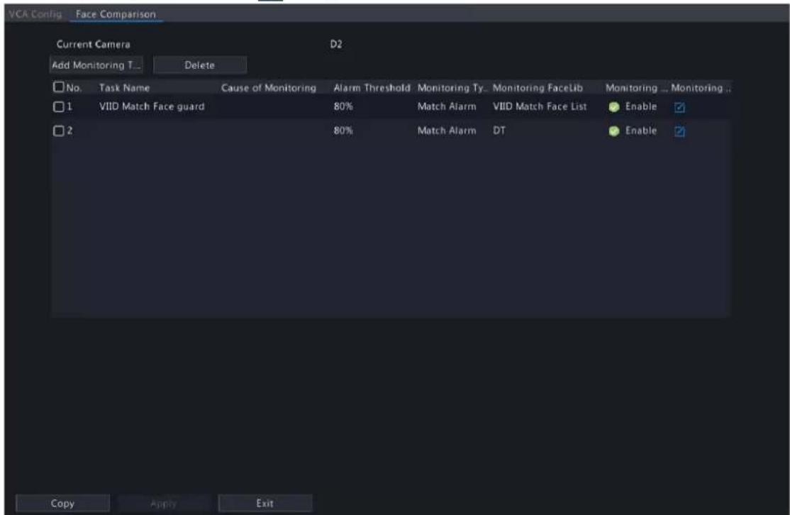
- Configure monitoring tasks. A monitoring task of "DefaultList 80% Match Alarm" is enabled by default. You can click to modify it, or click Add Monitoring Task to add more.
(1) Click Add Monitoring Task.

(2) Complete the monitoring task settings.
| Parameter Description | |
| Task Name Enter a name | for the monitoring task. |
| Enable Enable/disable the | monitoring task. |
| Cause of Monitoring Enter | the cause of the monitoring task. |
| Monitoring List | Select a face list from the Monitoring List drop-down list or click Add Face List to create a face list to monitor. |
| Alarm Threshold Set the | alarm threshold by dragging the slider. The NVR takes snapshots when the similarity between a detected face and a face image in the monitoring list reaches the threshold. Default: 80.The higher the alarm threshold, the more accurate the matching result. |
| Monitoring Type Select the | monitoring type.Match Alarm: A match alarm occurs when the similarity between a detected face and a face image in the monitoring list reaches the alarm threshold.Not Match Alarm: A not match alarm occurs when the similarity between a detected face and a face image in the monitoring list fails to reach the alarm threshold.All: An alarm occurs when a face is detected. |
| Monitoring Schedule | Set the monitoring schedule. See Recording Schedule for details. |
| Match Trigger Action | Set the actions to be triggered by a match alarm. See Alarm-triggered Actions for details. |
| Not Match Trigger Action | Set the actions to be triggered by a not match alarm. See Alarm-triggered Actions for details. |
(3) Click OK.
- (Optional) To apply the monitoring tasks to other cameras, click Copy, select the desired monitoring task(s) and camera(s), and then click OK.
- Click Apply.
View Library Sync Status
This function is only available to cameras with face recognition support and camera side analysis enabled. Library sync indicates the sync of face libraries from NVR to IPC. After IPC receives a face list, it can compare the captured faces with the face images in the face list and upload the comparison results to NVR.
Click Library sync state to view the sync status of face lists and faces in the face lists from NVR to IPC. You may manually synchronize the face lists in Not Started state.
• View faces by status: Select a state from the Sync Status drop-down list to view faces in this state.
- Manually sync face lists: Select the face list to be synced and click Manual sync. If a face in a face list is not synced successfully, you can manually sync the face list.
Other Operations
| Operation Description | |
| Delete Delete the selected monitoring task(s). | |
 | Enable/disable the monitoring task. |
| Edit the monitoring task. | |
View Real-time Snapshots
- Right-click on the live view page and select Preview Mode > Smart, then the real-time snapshots are shown on the right.
- Click a snapshot to view detailed information. See Face Recognition for details.
6.1.2 Perimeter Protection
Perimeter protection includes cross line detection, intrusion detection, enter area, and leave area.
6.1.2.1 Cross Line Detection
Cross line detection detects objects crossing a user-specified virtual line in a specified direction. The NVR takes snapshots and reports an alarm when the detection rule is triggered.

Note:
- Before you use camera side analysis, make sure an intelligent server with Platform Communication Type set to LAPI is enabled on the camera.
- The functions and parameters supported by camera side analysis and NVR side analysis are different.
• To perform this function on the camera side, enable Intelligent Mark under Menu > System > Basic.
Configure Cross Line Detection
- Go to Menu > VCA > VCA Config.
- Select a camera.
- Select Cross Line Detection and click to configure it.

- Set detection rules. The 4 detection rules shall be set separately. The following takes Rule 1 as an example.
| Parameter Description | |
| Detection Line | Select Rule 1, click and the full screen is displayed. Click on the image and drag to draw a detection line. The line defaults to A<->B direction. You can modify it as needed. Right-click to exit the full screen. |
| Trigger Direction Select | the direction from which the object crosses the line to trigger an alarm.A->B: A cross line alarm occurs when an object crossing the line from A to B is detected.B->A: A cross line alarm occurs when an object crossing the line from B to A is detected.A<->B (default): A cross line alarm occurs when an object crossing the line from A to B or from B to A is detected. |
| Sensitivity Set the sensitivity by dragging the slider.The higher the sensitivity, the more likely cross line behaviors will be detected, but the false alarm rate will increase. | |
| Priority | Select the priority of the detection rule, including High, Medium, and Low.The NVR detects the rule that is triggered first by default. If multiple rules are triggered at the same time, the NVR detects the rule with higher priority. |
| Object Type | Select the object(s) to be detected, including Motor Vehicle, Non-Motor Vehicle, and Pedestrian. |
- Under the Advanced tab, you can filter objects by size. For example, if you have selected Motor Vehicle as a detection object, after you set the Max. Size and Min. Size for it, motor vehicles larger than the max. size and smaller than the min. size will not be detected.
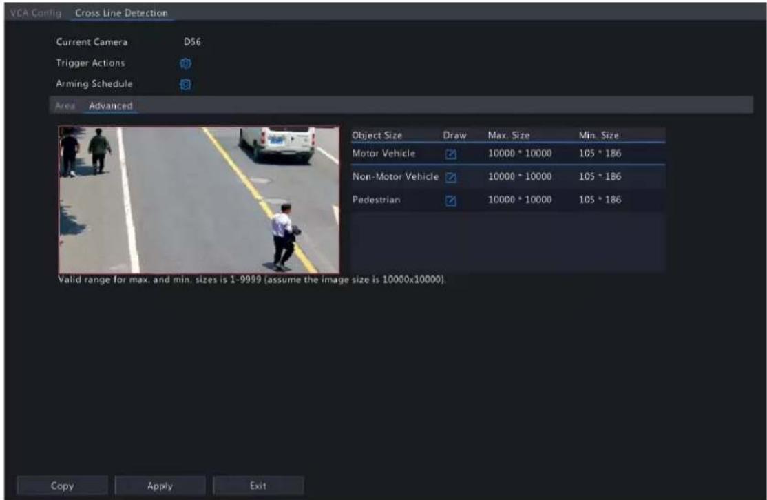
(1) Select an object type and click 📋. A Max. Size box and a Min. Size box appear in the left preview window.
(2) Modify the max./min. size by adjusting the size of the box as follows: Point to a handle of the box and drag to resize it.
Note:
- The Max. Size and Min. Size settings take effect after you select the object as a detection object.
-
The width and height of the maximum size must be greater than that of the minimum size.
-
Set the alarm-triggered actions and arming schedule. See Alarm-triggered Actions and Arming Schedule for details.
-
(Optional) To apply the same settings to other cameras, click Copy, select the desired setting(s) and camera(s), and then click OK.
- Click Apply.
View Real-time Snapshots
- Right-click on the live view page and select Preview Mode > Smart, then the real-time snapshots are shown on the right.
- Click a snapshot to view detailed information. See Perimeter Protection for details.
6.1.2.2 Intrusion Detection
Intrusion detection detects objects entering a user-specified area and staying for a preset time. The NVR takes snapshots and reports an alarm when the detection rule is triggered.

Note:
- Before you use camera side analysis, make sure an intelligent server with Platform Communication Type set to LAPI is enabled on the camera.
- The functions and parameters supported by camera side analysis and NVR side analysis are different.
• To perform this function on the camera side, enable Intelligent Mark under Menu > System > Basic.
Configure Intrusion Detection
- Go to Menu > VCA > VCA Config.
- Select a camera.
- Select Intrusion Detection and click to configure it.

- Set detection rules. The 4 detection rules shall be set separately. The following takes Rule 1 as an example.
| Parameter Description | |
| Detection Area | Select Rule 1, click and the full screen is displayed, then draw a detection area.Click on the image and drag to draw a line. Repeat the action to draw more lines to form an enclosed shape as needed. Up to 6 lines are allowed. Right-click to exit the full screen.Note: For a rule in Drawn state, you can click to redraw a detection area. To delete a detection area, click |
| Sensitivity Set the sensitivity by dragging the slider.The higher the sensitivity, the more likely intrusion behaviors will be detected, but the false alarm rate will increase. | |
| Time Threshold(s) Set | the time threshold by dragging the slider.If an object stays in the detection area for the set time, an intrusion alarm will be triggered. |
| Percentage Set the percentage by dragging the slider.If the proportion of the object size to the detection area size reaches the set value, an intrusion alarm will be triggered. | |
| Priority | Select the priority of the detection rule, includingHigh, Medium, andLow.The NVR detects the rule that is triggered first by default. If multiple rules are triggered at the same time, the NVR detects the rule with higher priority. |
| Object Type | Select the object(s) to be detected, includingMotor Vehicle, Non-Motor Vehicle, and Pedestrian. |
- Under the Advanced tab, you can filter objects by size. For example, if you have selected Motor Vehicle as a detection object, after you set the Max. Size and Min. Size for it, motor vehicles larger than the max. size and smaller than the min. size will not be detected.

(1) Select an object type and click Z. A Max. Size box and a Min. Size box appear in the left preview window.
(2) Modify the max./min. size by adjusting the size of the box as follows: Point to a handle of the box and drag to resize it.
Note:
- The Max. Size and Min. Size settings take effect after you select the object as a detection object. - The width and height of the maximum size must be greater than that of the minimum size.
-
Set the alarm-triggered actions and arming schedule. See Alarm-triggered Actions and Arming Schedule for details.
-
(Optional) To apply the same settings to other cameras, click Copy, select the desired setting(s) and camera(s), and then click OK.
-
Click Apply.
View Real-time Snapshots
-
Right-click on the live view page and select Preview Mode > Smart, then the real-time snapshots are shown on the right.
-
Click a snapshot to view detailed information. See Perimeter Protection for details.
6.1.2.3 Enter Area Detection
Enter area detection detects objects entering a user-specified area. The NVR takes snapshots and reports an alarm when the detection rule is triggered.

Note:
- Before you use camera side analysis, make sure an intelligent server with Platform Communication Type set to LAPI is enabled on the camera.
- The functions and parameters supported by camera side analysis and NVR side analysis are different.
• To perform this function on the camera side, enable Intelligent Mark under Menu > System > Basic.
Configure Enter Area Detection
- Go to Menu > VCA > VCA Config.
- Select a camera.
- Select Enter Area and click to configure it.
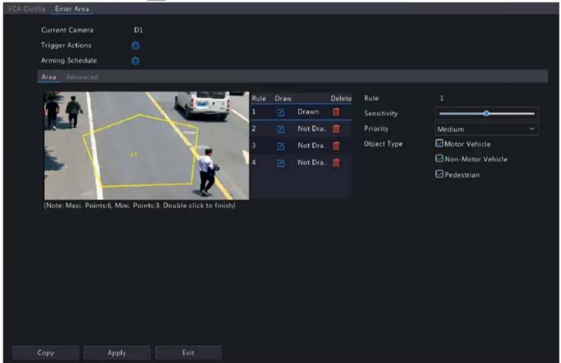
- Set detection rules. The 4 detection rules shall be set separately. The following takes Rule 1 as an example.
| Parameter Description | |
| Detection Area | Select Rule 1, click and the full screen is displayed, then draw a detection area.Click on the image and drag to draw a line. Repeat the action to draw more lines to form an enclosed shape as needed. Up to 6 lines are allowed. Right-click to exit the full screen.Note: For a rule in Drawn state, you can click to redraw a detection area. To delete a detection area, click |
| Sensitivity Set the sensitivity by dragging the slider.The higher the sensitivity, the more likely entry behaviors will be detected, but the false alarm rate will increase. | |
| Priority | Select the priority of the detection rule, including High, Medium, and Low.The NVR detects the rule that is triggered first by default. If multiple rules are triggered at the same time, the NVR detects the rule with higher priority. |
| Object Type | Select the object(s) to be detected, including Motor Vehicle, Non-Motor Vehicle, and Pedestrian. |
- Under the Advanced tab, you can filter objects by size. For example, if you have selected Motor Vehicle as a detection object, after you set the Max. Size and Min. Size for it, motor vehicles larger than the max. size and smaller than the min. size will not be detected.

(1) Select an object type and click Z. A Max. Size box and a Min. Size box appear in the left preview window.
(2) Modify the max./min. size by adjusting the size of the box as follows: Point to a handle of the box and drag to resize it.
Note:
- The Max. Size and Min. Size settings take effect after you select the object as a detection object.
-
The width and height of the maximum size must be greater than that of the minimum size.
-
Set the alarm-triggered actions and arming schedule. See Alarm-triggered Actions and Arming Schedule for details.
-
(Optional) To apply the same settings to other cameras, click Copy, select the desired setting(s) and camera(s), and then click OK.
-
Click Apply.
View Real-time Snapshots
- Right-click on the live view page and select Preview Mode > Smart, then the real-time snapshots are shown on the right.
- Click a snapshot to view detailed information. See Perimeter Protection for details.
6.1.2.4 Leave Area Detection
Leave area detection detects objects leaving a user-specified area. The NVR takes snapshots and reports an alarm when the detection rule is triggered.
Note:
- Before you use camera side analysis, make sure an intelligent server with Platform Communication Type set to LAPI is enabled on the camera.
- The functions and parameters supported by camera side analysis and NVR side analysis are different.
• To perform this function on the camera side, enable Intelligent Mark under Menu > System > Basic.
Configure Leave Area Detection
- Go to Menu > VCA > VCA Config.
- Select a camera.
- Select Leave Area and click to configure it.

- Set detection rules. The 4 detection rules shall be set separately. The following takes Rule 1 as an example.
| Parameter Description | |
| Detection Area | Select Rule 1, click and the full screen is displayed, then draw a detection area.Click on the image and drag to draw a line. Repeat the action to draw more lines to form an enclosed shape as needed. Up to 6 lines are allowed. Right-click to exit the full screen.Note: For a rule in Drawn state, you can click to redraw a detection area. To delete a detection area, click |
| Sensitivity Set the sensitivity by dragging the slider.The higher the sensitivity, the more likely leaving behaviors will be detected, but the false alarm rate will increase. | |
| Priority | Select the priority of the detection rule, including High, Medium, and Low.The NVR detects the rule that is triggered first by default. If multiple rules are triggered at the same time, the NVR detects the rule with higher priority. |
| Object Type | Select the object(s) to be detected, including Motor Vehicle, Non-Motor Vehicle, and Pedestrian. |
- Under the Advanced tab, you can filter objects by size. For example, if you have selected Motor Vehicle as a detection object, after you set the Max. Size and Min. Size for it, motor vehicles larger than the max. size and smaller than the min. size will not be detected.

(1) Select an object type and click ☑. A Max. Size box and a Min. Size box appear in the left preview window.
(2) Modify the max./min. size by adjusting the size of the box as follows: Point to a handle of the box and drag to resize it.
Note:
- The Max. Size and Min. Size settings take effect after you select the object as a detection object.
-
The width and height of the maximum size must be greater than that of the minimum size.
-
Set the alarm-triggered actions and arming schedule. See Alarm-triggered Actions and Arming Schedule for details.
- (Optional) To apply the same settings to other cameras, click Copy, select the desired setting(s) and camera(s), and then click OK.
- Click Apply.
View Real-time Snapshots
- Right-click on the live view page and select Preview Mode > Smart, then the real-time snapshots are shown on the right.
- Click a snapshot to view detailed information. See Perimeter Protection for details.
6.1.3 Object Detection
Object detection detects certain objects in the specified area. The NVR takes snapshots and reports an alarm when the detection rule is triggered.
6.1.3.1 Traffic Monitoring
Receive traffic monitoring alarm for IPCs.
- Go to Menu > VCA > VCA Config.
- Select a camera.
- Check ☐ to enable Traffic Monitoring, then the NVR will receive an alarm form IPCs. If unchecked, the alarm will not be received.
说明:Please log in to the Web interface of IPC to configure traffic monitoring function. See Network Camera User Manual for details.
6.1.4 Exception Detection & Statistics
Exception detection and statistics includes defocus detection, scene change, object removed, and object left behind detection.
6.1.4.1 Defocus Detection
Defocus detection detects lens defocus. The NVR takes snapshots and reports an alarm when the detection rule is triggered.
- Go to Menu > VCA > VCA Config.
- Select a camera.
- Select Defocus Detection and click to configure it.
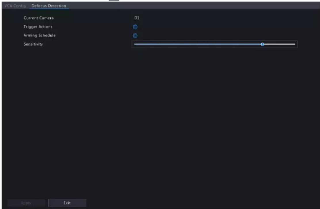
- Set the alarm-triggered actions and arming schedule. See Alarm-triggered Actions and Arming Schedule for details.
- Set the sensitivity by dragging the slider. The higher the sensitivity, the more likely defocus will be detected, but the false alarm rate will increase.
- Click Apply.
6.1.4.2 Scene Change Detection
Scene change detection detects the change of surveillance scene caused by external factors such as intentional camera movement. The NVR takes snapshots and reports an alarm when the detection rule is triggered.
- Go to Menu > VCA > VCA Config.
- Select a camera.
- Select Scene Change Detection and click to configure it.

- Set the alarm-triggered actions and arming schedule. See Alarm-triggered Actions and Arming Schedule for details.
- Set the sensitivity by dragging the slider. The higher the sensitivity, the more likely scene change behaviors will be detected, but the false alarm rate will increase.
- Click Apply.
6.1.4.3 Object Removed Detection
Object removed detection detects objects removed from a user-specified area for a preset time. The NVR takes snapshots and reports an alarm when the detection rule is triggered.
- Go to Menu > VCA > VCA Config.
- Select a camera.
- Select Object Removed and click to configure it.

- Set detection rules. The 4 detection rules shall be set separately. The following takes Rule 1 as an example.
| Parameter Description | |
| Detection Area | Select Rule 1, click and the full screen is displayed, then draw a detection area.Click on the image and drag to draw a line. Repeat the action to draw more lines to form an enclosed shape as needed. Up to 6 lines are allowed. Right-click to exit the full screen.Note: For a rule in Drawn state, you can click to redraw a detection area. To delete a detection area, click |
| Sensitivity Set the sensitivity by dragging the slider.The higher the sensitivity, the more likely object removal behaviors will be detected, but the false alarm rate will increase. | |
| Time Threshold(s) Set the time threshold by dragging the slider.If an object is removed from the detection area for the set time, an alarm will be triggered. | |
-
Set the alarm-triggered actions and arming schedule. See Alarm-triggered Actions and Arming Schedule for details.
-
Click Apply.
6.1.4.4 Object Left Behind Detection
Object left behind detection detects objects left behind in a user-specified area for a preset time. The NVR takes snapshots and reports an alarm when the detection rule is triggered.
- Go to Menu > VCA > VCA Config.
- Select a camera.
- Select Object Left Behind and click to configure it.

- Set detection rules. The 4 detection rules shall be set separately. The following takes Rule 1 as an example.
| Parameter Description | |
| Detection Area | Select Rule 1, click and the full screen is displayed, then draw a detection area.Click on the image and drag to draw a line. Repeat the action to draw more lines to form an enclosed shape as needed. Up to 6 lines are allowed. Right-click to exit the full screen.Note: For a rule inDrawnstate, you can click to redraw a detection area. To delete a detection area, click |
| Sensitivity Set the sensitivity by dragging the slider.The higher the sensitivity, the more likely object left behind behaviors will be detected, but the false alarm rate will increase. | |
| Time Threshold(s) Set the time threshold by dragging the slider.If an object is left behind in the detection area for the set time, an alarm will be triggered. | |
-
Set the alarm-triggered actions and arming schedule. See Alarm-triggered Actions and Arming Schedule for details.
-
Click Apply.
6.1.4.5 Auto Tracking
Auto tracking detects moving objects in the live video and tracks the first object detected.
- Go to Menu > VCA > VCA Config.
- Select a camera.
- Select Auto Tracking and click to configure it.

- Set the tracking parameters.
| Parameter Description | |
| Tracking Area In the | PTZ operation area, use the PTZ control buttons to adjust the tracking area, including shooting angle, zoom, focus, iris and rotation speed. |
| Tracking Mode Panoramic: Continuously tracks objects that appear in the tracking area until they disappear from the tracking area. | |
| TrackingTimeout(s) | Set the maximum tracking time. The device stops tracking when the object disappears or the set time is up. Range: 1 to 300. Default: 30. |
| Zoom | Select the tracking zoom ratio:AutoorCurrent Zoom.The default isAuto.Auto: Automatically adjusts the zoom ratio according to the tracking distance, focusing more on the object behavior.Current Zoom: Keeps the zoom ratio when the object is tracked, focusing more on the whole monitoring scene. |
-
Set the alarm-triggered actions and arming schedule. See Alarm-triggered Actions and Arming Schedule for details.
-
Click Apply.
6.1.5 Temperature Detection
Temperature detection includes fire detection, smoking detection, temperature detection, smoke and fire detection.
6.1.5.1 Fire Detection
Receive fire detection alarm information from IPCs. If the IPC detects a fire or other high temperature in a specified area, it will take snapshots and report an alarm to NVR.

Note: This function requires the camera support (camera-side analysis).
- Go to Menu > VCA > VCA Config.
- Select a camera.
- Select Fire Detection and click to configure it.
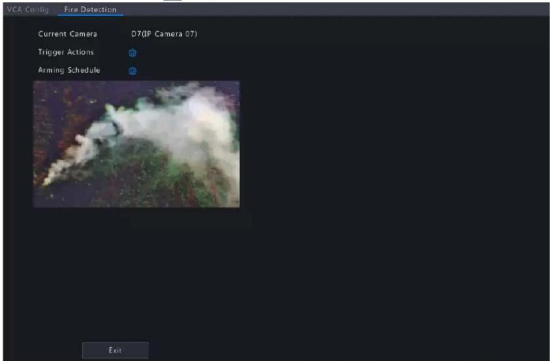
- Set the alarm-triggered actions and arming schedule. See Alarm-triggered Actions and Arming Schedule for details.
6.1.5.2 Smoking Detection
Smoking detection detects people smoking in a specified area in live video. The NVR takes snapshots and reports an alarm when the detection rule is triggered.
- Go to Menu > VCA > VCA Config.
- Select a camera.
- Select Smoking Detection and click to configure it.

- Set detection rules. The 4 detection rules shall be set separately. The following takes Rule 1 as an example.
| Parameter Description | |
| Detection Area | Select Rule 1, click and the full screen is displayed, then draw a detection area.Click on the image and drag to draw a line. Repeat the action to draw more lines to form an enclosed shape as needed. Up to 6 lines are allowed. Right-click to exit the full screen.Note: For a rule in Drawn state, you can click to redraw a detection area. To delete a detection area, click |
| Sensitivity Set the sensitivity by dragging the slider.The higher the sensitivity, the more likely smoking behaviors will be detected, but the false alarm rate will increase. | |
-
Set the alarm-triggered actions and arming schedule. See Alarm-triggered Actions and Arming Schedule for details.
-
Click Apply.
6.1.5.3 Temperature Measurement
Receive temperature measurement alarm information from IPCs. The IPC detects the temperature of objects in a specified area, and it will take snapshots and report an alarm to NVR when the detection rule is triggered.

Note: This function requires the camera support (camera-side analysis).
- Go to Menu > VCA > VCA Config.
- Select a camera.
- Select Temperature Measurement and click to configure it.

- Set the alarm-triggered actions and arming schedule. See Alarm-triggered Actions and Arming Schedule for details.
6.1.6 People Counting
People counting includes people flow counting and crowd density monitoring.
6.1.6.1 People Flow Counting
People flow counting counts people passing a specified tripwire in a user-defined area.
Configure People Flow Counting
- Go to Menu > VCA > VCA Config.
- Select a camera.
- Select People Flow Counting and click to configure it.

- Set the people flow counting rule.
| Parameter Description | |
| Draw Area | Clickenter the full screen and then draw a detection area.Click on the image and drag to draw a line. Repeat the action to draw more lines to form an enclosed shape as needed. Up to 6 lines are allowed. Right-click to exit the full screen. |
| Draw Tripwire | Clickenter the full screen and then draw a tripwire. Only 1 tripwire is allowed. Right-click to exit the full screen. |
| Direction of arrow Set the entry direction.A- >B: A to B is entry, B to A is exit.B- >A: B to A is entry, A to B is exit. | |
| Counting Type | Select the counting type: Total, People Entered, or People Exited. Total is the default counting type.Total: Displays the number of people entering and leaving the detection area.People Entered: Displays the number of people entering the detection area. An entry is counted as a person crossesthe tripwire in the direction of the arrow and passes through the detection area.People Exited: Displays the number of people leaving the detection area. An exit is counted as an object crosses the tripwire in the opposite direction of the arrow and passes through the detection area.Note:Before use, you need to enable people counting OSD under Menu > Camera > OSD.People that loiter in the detection area, cross the tripwire only, or cross the detection area only are not counted. |
| Report Interval(s) Set the time interval for reporting people flow statistics. Default: 60. Range: 1 to 60. The NVR reports people flow statistics to the uplink platform at set intervals. The uplink platform must subscribe to the function to receive the statistics. | |
| Enable Clear by Schedule | Select the Enable Clear by Schedule check box and set the time to clear people counting statistics. |
| Clear At The clearing time defaults to 00:00:00. You can modify it as needed. The NVR will clear people counting statistics on the OSD at the set time everyday. This operation does not affect statistics and data reporting. | |
| Clear Counting Result | Clickclear people counting statistics displayed on the live video immediately. This operation only affects the people counting OSD and does not affect statistics and data reporting. |
- To be alerted when the number of people in the detection area exceeds a certain number, you can enable and configure People Present Alarm under Menu > Alarm > People Present Alarm. See People Present Alarm for details.
- Click Apply.
View Real-time Statistics
Right-click on the live view page and select Preview Mode > Smart, then the real-time people statistics are shown on the right. See People Flow Counting for details.
6.1.6.2 Crowd Density Monitoring
Crowd density monitoring monitors the number of people in a specified area and triggers an alarm if the number exceeds the set alarm threshold.
- Go to Menu > VCA > VCA Config.
- Select a camera.
- Select Crowd Density Monitoring and click to configure it.

- Set the crowd density monitoring rule.
| Parameter Description | |
| Detection Area A detection box | is displayed in the left preview window by default. You can adjust the position of it or draw an area as needed. Only 1 detection area is allowed.Adjust the position of the default detection area: Point to a border of the area and drag it to the desired position.Draw an area: Click [icon] the full screen is displayed. Click on the image and drag to draw a line. Repeat the action to draw more lines to form an enclosed shape as needed. Up to 6 lines are allowed. Right-click to exit the full screen. |
| Report Interval(s) Set the time | interval for reporting crowd density statistics. Default: 60.Range: 1 to 60.The device reports crowd density statistics to the uplink platform at set intervals. The uplink platform must subscribe to the function to receive the statistics. |
| Minor Alarm A minor alarm is | triggered when the number of people in the specified area reaches the set value.Select the Minor Alarm check box and set the number of people to trigger minor alarms. Range: 1 to 40. |
| Major Alarm A major alarm is | triggered when the number of people in the specified area reaches the set value. The value of major alarm must be greater than that of minor alarm.Select the Major Alarm check box and set the number of people to trigger major alarms. Range: 1 to 40. |
| Critical Alarm A critical alarm is | triggered when the number of people in the specified area reaches the set value. The value of critical alarm must be greater than that of major alarm.Select the Critical Alarm check box and set the number of people to trigger critical alarms. Range: 1 to 40. |
natural_image
Street scene with two people walking on a road, a car, and yellow lane markings (no visible text or symbols)




- Enable Alarm Sound for minor alarm, major alarm, and critical alarm, set the alarm audio and playback times, then the camera will play the alarm audio when an alarm occurs.
- Set the arming schedule. See Arming Schedule for details.
- Click Apply.
6.1.7 Plate Detection
Configure plate detection and plate comparison.
6.1.7.1 Plate Detection
Detect license plates in the live video and take snapshots.

Note: This function is only available to the camera side analysis.
- Go to Menu > VCA > VCA Config.
- Select a camera.
- Select Plate Detection to enable this function.
6.1.7.2 Plate Comparison
Configure vehicle monitoring tasks so that the NVR can report alarms according to the matching result of the captured plate numbers and the plate numbers in plate lists. To use plate comparison function, enable Plate Detection or Configure VIID Local first.

Note:
- This function is only available to the NVR side analysis.
• To configure plate list and plate library, see Plate List for details.

Note: This function is only available to the NVR side analysis.
- Go to Menu > VCA > VCA Config.
- Select a camera.
- Select Plate Comparison and click to configure it.

- Click Add Monitoring Task.

- Complete the monitoring task settings.
| Parameter Description |
| Task Name Enter a name for the monitoring task. |
| Enable Enable/disable the monitoring task. |
| Cause of Monitoring Enter the cause of the monitoring task. |
| Monitoring Channels Select the channel(s) to monitor. |
| Monitoring List Select the plate list to monitor. Only 1 plate list is allowed. |
| Monitoring Schedule Set the monitoring schedule as needed. See Recording Schedule for details. |
| Match Trigger Action Set the action(s) to be triggered when a captured plate number matches a plate number in the monitoring list. See Alarm-triggered Actions for details. |
| Not Match Trigger Action Set the action(s) to be triggered when a captured plate number does not match any plate number in the monitoring list. See Alarm-triggered Actions for details. |
- Click OK.
Other Operations
| Operation Description | |
| Delete Delete the selected monitoring task(s). | |
 | Enable/disable the monitoring task. |
| Edit the monitoring task. | |
6.1.8 Alarm-triggered Actions
Configure actions to be triggered when an alarm occurs to alert user or the specified people.
Click right to Trigger Actions, set the actions, and then click OK.

Note: The actions supported may vary with NVR model and VCA function.
Some actions are detailed below.

Buzzer
The NVR makes a buzzing sound when an alarm occurs.
Pop-up Window
An alarm message pops up when an alarm occurs.
Push Alarm
An alarm information will be pushed to the upper platform when an alarm occurs.
Recording
The NVR records video from the selected camera when an alarm occurs.
Goto Preset
A PTZ camera moves to a preset position when an alarm occurs.

Configure this action as follows:
- Click

- Select the camera to perform this action and select the preset you want the camera to go to when an alarm occurs.
Note: Before use, you need to configure presets on the PTZ camera. See Network Camera User Manual for details.
- Click OK.
Note: To delete the action, click
Preview
The NVR plays the live video of the specified camera(s) when an alarm occurs. To perform this action, you need to configure Max. Alarm-Triggered Live View Windows (1/4/9 available) under Menu > System > Preview.

The live view page displayed in the event of alarms varies depending on the number of linked cameras and the number of alarm-triggered live view windows. When an alarm occurs, the live view page shows the live video from the linked camera(s) with a red frame; when the alarm ends, the live view page returns to the original state.
- When Max. Alarm-Triggered Live View Windows is set to 1 Window, the live view page plays live video in one window. If more than one camera is linked, the live video switches at 5s.
natural_image
Street scene with two people walking on a road, a car parked nearby, and yellow lane markings (no visible text or symbols)- When Max. Alarm-Triggered Live View Windows is set to 4 Windows, the live view page plays the live video of each camera in 4-split mode. If more than 4 cameras are linked, the live video switches at 5s. Live view page with 3 cameras linked:
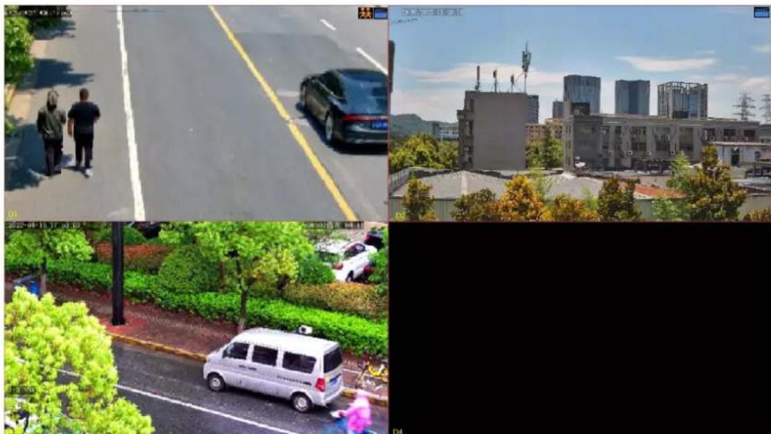
natural_image
Composite image showing three scenes: a street scene with two people walking, a cityscape with buildings and surveillance equipment, and a parked van in a park setting (no visible text or symbols)Live view page with 5 cameras linked:

natural_image
Collage of six urban and transportation scenes including a car, police van, city skyline, and highway (no visible text or symbols)- When Max. Alarm-Triggered Live View Windows is set to 9 Windows, the live view page plays the live video of each camera in 9-split mode. If more than 9 cameras are linked, the live video switches at 5s.
Alarm Output
A third-party device is triggered to raise an alarm when it receives an alarm output by the NVR.
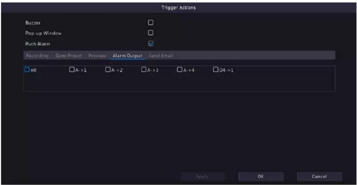
Alarm Sound
The selected camera plays an audio alarm when an alarm occurs. This action is only available to cameras that support alarm sound, and the day/night mode is available on certain cameras only.

Configure this action as follows:
- Select the Alarm Sound check box, select the alarm mode, and configure other parameters as needed.

| Mode Description | |
| Note: Up to 4 time periods are allowed per day, and the time periods cannot overlap. | |
| Audio Select the audio file to be played by the camera when an alarm occurs. By default, 13 audio files are available. You can configure the audio files on the camera's Web interface.Note: The number of built-in audio files varies depending on the camera model, and up to 5 audio files are allowed on certain models. | |
| Repeat Set the number of times the audio file to be played when an alarm occurs. Range: 1 to 50. | |
-
(Optional) To apply the same settings to other days, select the desired day(s) after Copy To.
-
Click OK.
Flashing Light
The illuminator of the selected camera flashes for a certain length of time when an alarm occurs. This action is only available to cameras that support flashing light, and the day/night mode is available on certain cameras only.
![Trigger Actions Buzzer Pop-up Window Push Alarm Recording Goto Preset Preview Alarm Output Alarm Sound Flashing Light Send Email Flashing Light Select Mode Day/Night Mode Custom Mode Blink Time(s) 10 [5 - 60] Select day Mon Day/Night Flashing Light Day Night Copy To All Mon Tue Wed Thu Fr Sat Sun Apply OK Cancel](/content/2026/06/1364532/images/79124770adf63993f89bf90aab316c0d0d46c851e305d7a8cf3baf4218695fc4.jpg)
Configure this action as follows:
- Select the Flashing Light check box, select the alarm mode, and configure other parameters as needed.
| Mode Description | |
| Day/Night Mode Select | the day and time (day/night) during which flashing light is enabled.Note: The camera automatically switches to day or night mode according to the ambient lighting. See Network Camera User Manual for details. |
| Custom Mode Select | the day and time (start/end time) in which flashing light is enabled. Note: Up to 4 time periods are allowed per day, and the time periods cannot overlap. Note: Up to 4 time periods are allowed per day, and the time periods cannot overlap. |
| Blink Time(s) Set the duration that the illuminator flashes when an alarm occurs. | |
- (Optional) To apply the same settings to other days, select the desired day(s) after Copy To.
- Click OK.
Snapshot
The NVR triggers the linked camera to capture a snapshot when an alarm occurs.


Note: This action is only available to certain alarm functions such as motion detection and human body detection, and is not available to VCA functions.
Send Email
The NVR sends an email with alarm information to the specified email address(es) when an alarm occurs. Please set the recipient information in Email. Up to 6 recipients are allowed.
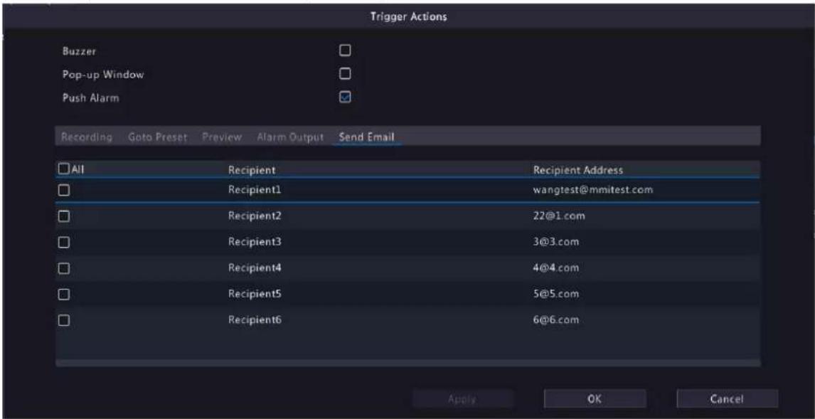
Camera Linkage
Click the Camera Linkage tab, select Panoramic Linkage, and then the panoramic camera will link to a PTZ camera when an alarm occurs.

6.1.9 Arming Schedule
Configure an arming schedule to determine when the NVR receives alarms and performs predefined alarm-triggered actions.
Click right to Arming Schedule, configure the schedule as needed, and then click OK.

On certain NVRs, the Arming Schedule page shows as follows:


Note:
- Up to 4 or 8 time periods are allowed per day, and the time periods cannot overlap.
- (Optional) To apply the same schedule to other days, select the desired day(s) after Copy To.
- The number of arming time periods available varies by function.
- If a SIP camera is connected to the NVR and configured with camera side analysis of Intrusion Detection, Cross Line Detection, Enter Area, Leave Area, or Human Body Detection, the arming schedule configured for these functions on the NVR will be synchronized to the camera.
6.2 Analyzer Configuration
View the analyzer usage and change the analysis mode.
Analyzer is a smart chip used to process face recognition, perimeter protection, ultra motion detection, etc. The analyzer capacity varies by NVR model, which requires you to allocate channels appropriately.
- Go to Menu > VCA > Analyzer Config.
- View the analyzer's capacity usage. The analyzer's capacity is divided into the number of video stream analysis channels and the number of image stream analysis channels. Video stream analysis is NVR-side analysis, and image stream analysis is camera-side analysis.
The settings shown in the figure below means: The NVR has 4 analyzers. Analyzer 3 has been used for 1 video stream channel and 1 image stream channel, and can be used for 7 video stream channels or 15 image stream channels.

6.3 Library Management
Manage face library and work clothes library.
6.3.1 Face List
Configure face lists for face comparison.
Configure Face List
- Go to Menu > VCA > Library Management > Face List.

- Configure face lists. A face list is created by default. Up to 128 face lists are allowed.
| Parameter Description | |
| [63YC] | (1) Clickadd a face list. (2) Enter the list name.(3) (Optional) Select theSet as Dynamic Librarycheck box to set the face list as a dynamic list. The captured face images that do not match any face image in face lists will be automatically added to the dynamic list.Note:If there is no dynamic face list, you can add a new face list and set it as a dynamic list. You can only configure a dynamic list while adding a face list.Only 1 dynamic list is allowed. To change the dynamic list, you need to delete the original dynamic list and add a new one.(4) Click OK. (2) Enter the list name.(3) (Optional) Select theSet as Dynamic Librarycheck box to set the face list as a dynamic list. The captured face images that do not match any face image in face lists will be automatically added to the dynamic list.Note:If there is no dynamic face list, you can add a new face list and set it as a dynamic list. You can only configure a dynamic list while adding a face list.Only 1 dynamic list is allowed. To change the dynamic list, you need to delete the original dynamic list and add a new one.(4) Click OK. |
 | Delete the selected face list(s).Note:Deleting a face list will also delete its related historical alarm records. Please handle with caution. |
 /click to edit the face list. You can only edit the list name. indicates that the face list cannot be edited. /click to edit the face list. You can only edit the list name. indicates that the face list cannot be edited. | |
  icates that the face icates that the face |  is a dynamic list. indicates that the face lis not a dynamic list. is a dynamic list. indicates that the face lis not a dynamic list. |
| [X6VT] ! [CTDO] :k / to enable/disa |   Snapshot to Library. Snapshot to Library. |
- Import face images. You can import one by one or in batches.
- Import one by one
(1) Click Add.

(2) Click Select Image to import the desired face image.
(3) Complete the face information including face library, name, gender, date of birth, nationality, province, city, ID type and ID number.
(4) Click OK.
- Import in batches
(1) Click Export Template.
(2) Select the location to save the template and click Backup.

Note: You can export the template to an external storage device (connect a storage device to the NVR) or a PC (log in to the NVR's web interface, go to Smart > List Management > Face List, click DefaultList, and then click Export Template).
(3) Complete the template with reference to the import guide.
(4) Click Import, select the template, and click Import.


Note: The number of images allowed for a file depends on the library capacity of the device.
Other Operations
| Parameter Description | |
| Search 1. Set search conditions. |  Select the modeling state: All, Modeled, Modeling Failed, Modeling, or Not Modeled.Select Name or ID No. and enter the name or ID number to search.2. Click Search.3. To clear the search conditions, click Reset. Select the modeling state: All, Modeled, Modeling Failed, Modeling, or Not Modeled.Select Name or ID No. and enter the name or ID number to search.2. Click Search.3. To clear the search conditions, click Reset. |
| Edit Select a face image and click Edit to modify its information. | |
| Model Model face images in Not Modeled or Modeling Failed status. | |
| Export Selected Export the selected face image(s). | |
| Export All Export all face images in the selected face list. | |
6.3.2 Work Clothes Library
Import work clothes images so the NVR can compare the detected clothes with the images in the work clothes library.
- Go to Menu > VCA > Library Management > Work Clothes Library.
- Set work clothes library.
| Parameter Description | |
 | (1) Clickadd a work clothes library.(2) Enter the library name.(3) Click OK.[WCY0]Note:Up to 8 work clothes libraries are allowed, and up to 50 images can be added to each library. Importing images captured from different angles can improve the detection accuracy. |
| [2838] | Clic  delete the selected library.Note:Deleting the library will disable the No Work Clothes Detection function of the library. delete the selected library.Note:Deleting the library will disable the No Work Clothes Detection function of the library. |
 | Clic  to edit the library name. to edit the library name. |
- Click Add to import work clothes images.
6.4 Plate List
Configure plate lists for vehicle monitoring.
Configure Plate List
- Go to Menu > VCA > Plate List.

- Configure plate lists. A plate list is created by default. You can add more as needed.
| Parameter Description | |
| Add | Click enter the list name, and click OK. Name OK Cancel |
| Delete | Select the list(s) you want to delete and click |
| Edit | Click to modify the list name. |
- Add plate numbers. You can add one by one or in batches.
- Add one by one
(1) Click Add.

(2) Enter the plate number.
(3) Click OK.
- Add in batches by importing a file
(1) Click Export Template.
(2) Select the location to save the template and click Backup.

Note: You can export the template to an external storage device (connect a storage device to the NVR) or a PC (log in to the NVR's web interface, go to Smart > Vehicle Control > Plate List, click DefaultList, and then click Export Template).
(3) Complete the template with reference to the import guide.
(4) Click Batch Import, select the template, and click Import.


Note: A progress bar is displayed during import. The import result will be displayed when the progress bar shows 100%.
Other Operations
| Parameter Description | |
| Delete a specific plate number. | |
| Delete Delete selected | plate number(s). |
| Delete All Delete all plate numbers in the selected plate list. | |
| Modify the plate number. | |
| Export Selected Export | the selected plate number(s). |
| Export All Export all plate numbers in the selected plate list. | |
| Refresh Refresh the plate list. | |
View Real-time Snapshots
- Right-click on the live view page and select Preview Mode > Smart, then the real-time vehicle snapshots are shown on the right.
- Click a snapshot to view detailed information. See Vehicle Monitoring for details.
6.5 Smart Preview
View real-time snapshots and statistics of VCA functions on the live view page, including motor vehicle, non-motor vehicle, human body, face and people flow counting.
Right-click on the live view page and select Preview Mode > Smart, then the real-time snapshots are displayed on the right.
Preview Interface
| Icon Description | |
 | Select the object type(s) for which you want to view real-time snapshots. means the motor vehicle, means the motor vehicle,  ans the non-motor vehicle, m [TYKE] the human body, and [REANS the face. ans the non-motor vehicle, m [TYKE] the human body, and [REANS the face. |
| [44A82] | Click to enter theSmart Display Configurationpage, on which two tabs are displayed:Alarm Subscriptionand ShowTime Attr Config.Alarm Subscriptiontab: You can subscribe to various alarms at the same time. If you want to view real-time alarm information on smart preview page, please configure VCA functions of of the corresponding alarm(s). For details, please refer toVCAConfiguration.ShowTime Attr Configtab: You can configure human body attributes, motor vehicle attributes, and non-motor vehicle attributes, and up to 3 items can be selected for each attribute type. By default, the first 3 items of human body attributes and non-motor vehicle attributes are selected; and vehicle color, vehicle brand, and vehicle type of motor vehicle attributes are selected. The attribute configuration is only available to mixed-traffic detection and road monitoring alarms. Note:If you enable [IMAGE] and a face exists in the human body or non-motor vehicle snapshot, only the first two selected items of each attribute type will be displayed on the smart preview page.Face is not enabled/face is enabled but not recognized: Note:If you enable [IMAGE] and a face exists in the human body or non-motor vehicle snapshot, only the first two selected items of each attribute type will be displayed on the smart preview page.Face is not enabled/face is enabled but not recognized: 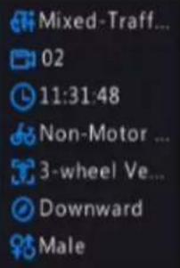 Face is enabled and recognized: Face is enabled and recognized:  |
| Open theGeneral Searchpage. | |
| Open theVCA Configpage. | |
| Clear real-time snapshots displayed on the live view page. Search records and statistics are not affected. |
6.5.1 Face Recognition
| Type Description | |
| Not Match Face Info 1. Select | a mismatched face snapshot. 2. Click on the snapshot to view more details. 2. Click on the snapshot to view more details. |
| Face Snapshot Info 1. Select a | face snapshot.2. Click on the snapshot to view more details. |
| Match Face Info 1. Select a m | matched face snapshot. The left image is the captured image, and the right image is the face image in the face list.2. Click on the snapshot to view more details. |

Note:
- In the View Details dialog box, a 10s video (5s before and 5s after the snapshot) is automatically played on the left, and the snapshot and its detailed information are displayed on the right.
- You can click + under a face snapshot or click Add to Face Library in the details page of a face snapshot to add the snapshot to the face list, and click search face images in face lists by this snapshot.
6.5.2 Perimeter Protection
View real-time snapshots of perimeter protection functions including cross line detection, intrusion detection, enter area detection and leave area detection.
- Select a snapshot.
- Click on the snapshot to view more details.
In the View Details dialog box, a 10s video (5s before and 5s after the snapshot) is automatically played on the left, and the snapshot and its detailed information including event type, camera name, time, and object type are displayed on the right.

6.5.3 Vehicle Monitoring
View vehicle monitoring information, vehicle snapshot information, and license plate matching/mismatching information.
- Select a vehicle snapshot.

- Click on the snapshot to view more details.

In the View Details dialog box, a 10s video (5s before and 5s after the snapshot) is automatically played on the left, and the snapshot and its detailed information including camera name, time, license plate number, vehicle color, and plate color are displayed on the right.
6.5.4 Object Detection
View real-time snapshots of object detection functions including mixed-traffic detection and road monitoring. The following takes the mixed-traffic detection as an example.
6.5.4.1 Mixed-Traffic Detection
View real-time snapshots and detailed attributes of mixed-traffic detection, and the object types captured include motor vehicle, non-motor vehicle, human body and face. The displayed attributes can be customized. Please refer to ShowTime Attr Config for details.


Note: When a face is recognized, the smart preview page will display a close-up image of the face and an image of the captured object.
6.5.5 People Flow Counting
Select a scene and view real-time people flow statistics including the number of people entering/leaving/currently allowed/present.
The green icon under People Present Alarm means the number of people present in the detection area does not exceed the set threshold. If the icon is red, it means the number of people present in the detection area exceeds the set threshold.
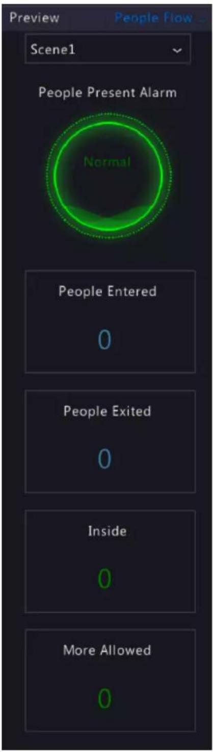
7 Network Configuration
Configure the network parameters of the NVR, such as IP address.

Note: The default IP address of network interface 1 is 192.168.1.30, and that of network interface 2 is 192.168.2.30.
7.1 Basic Configuration
Configure the network, mobile app, DDNS, email, etc.
7.1.1 Network Configuration
Configure IP address and other network parameters of the NVR.
- Go to Menu > Network > Basic > Network.

- Choose a working mode. Only multi-NIC NVRs support these three working modes.
| Working Mode Description |
| Multi-address Two NICs work independently. You need to configure the NICs separately. |
| Load Balance Two NICs use the same IP address and work together to share the sending and receiving bandwidth. |
| Net Fault-tolerance Two NICs use the same IP address, and if the primary NIC fails, the standby NIC takes over seamlessly to ensure uninterrupted network connection. |

Note: Switching working modes with 802.1x and ARP protection enabled will disable 802.1x and ARP protection.
- Configure the network parameters according to the actual network environment.

Note:
- For a multi-NIC NVR, you can choose an NIC as the default route. When the NVR connects to an external network, data will be forwarded via the default route.
- For an NVR with PoE ports, you can configure an IPv4 address for the internal NIC.
-
The MTU must be in the range of [576-1500]. To use IPv6, you must set MTU within [1280-1500], and make sure the IPv6 addresses of the NVR and PC are connected. To use functions such as live view, playback, make sure IPv4 addresses of the NVR and PC are also connected.
-
Click Apply.
7.1.2 EZCloud
With EZCloud you can manage and operate the NVR remotely on a mobile phone.
Configure EZCloud
- Go to Menu > Network > Basic > EZCloud. EZCloud is enabled by default.

- Add the NVR to cloud. See Add Device below.
- (Optional) Enable Snapshot Upload, and the NVR will upload images to cloud.
- Click Apply.
- Check the device status. If online, the current username will be displayed. If offline, the common cause will be displayed for your troubleshooting reference.

Note: You can also check the device status on the cloud website (en.ezcloud.uniview.com).
- (Optional) To delete the NVR from cloud, click Logout.
Add Device
Add the NVR to cloud using the app or cloud website.
Add NVR on app
- Scan the QR code with your mobile phone to download the app; or search EZView or EZLive at app store. The following steps take EZView as an example.
- Open the app, add the NVR with or without a cloud account.
- Add with a cloud account:
Sign up for a cloud account, and then log in to add the NVR.
(1) Tap Log In/Sign Up, follow the on-screen instructions to sign up and log in.
(2) On the Live View page, tap > , and choose a way to add the NVR.
- Add without a cloud account:
Scan the QR code using the app to add the NVR without a cloud account.
(1) Tap Try Now. The Live View screen is displayed.
(2) Tap > + > Add Without Signup, follow instructions to scan the QR code. You may also scan the QR code on the device body.
(3) The registered code is filled in automatically. The default username is "admin". Enter the device password, tap Login.

Note:
- To add the NVR without a cloud account, ensure that EZCloud and Add Without Signup are enabled on the NVR, and the NVR's admin password is a strong password.
- Certain functions will be unavailable on the app if the NVR is added without a cloud account.
Signup for a cloud account is required to use full functions on the app.
Add NVR on the cloud website
- Visit the EZCloud website address (en.ezcloud.uniview.com) using a Web browser.
-
Tap Sign Up, follow the on-screen instructions to sign up for a cloud account.
-
Log in to the account.

- Go to Device Management > My Cloud Device, click Add.

| Parameter Description | |
| Device Name Set a | device name that is easy to recognize. |
| Register Code | Enter the register code. You can find it on the EZCloud page. |
| Organization Choose | an organization for the NVR on the cloud.The default organization is root. You can add organizations at Organization Management > My Cloud Organization. |
- Click OK to add the NVR to cloud.
- Click Save.
7.1.3 DDNS
Configure DDNS so you can access the NVR on the LAN from the Internet by visiting a fixed domain name instead of the changing IP addresses.

Note: You can open the NVR's Web page by visiting http://server address/NVR's domain name using a Web browser.
- Go to Menu > Network > Basic > DDNS.
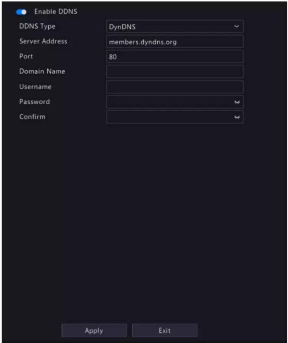
- Enable DDNS, choose a DDNS type, and configure the parameters.
- DynDNS/No-IP: Third-party DDNS service provider. Enter the domain name and username/password that you acquired from your DDNS service provider.
- Domain name: Domain name assigned by your DDNS service provider.
- Username and password: The corresponding username/password for your DDNS account.
- EZDDNS: DDNS service provided by Uniview. You can input a domain name, and then click Test to check its validity.

3. Click Apply.
7.1.4 Email
Configure email so the NVR can send alarm information to specified users through email when an alarm occurs.

Note: Select the Send Email checkbox on the Trigger Actions page before you start configuration.
- Go to Menu > Network > Basic > Email.

- Configure the parameters.
| Parameter Description | |
| Enable Server Authentication | SMTP server authentication, when enabled, can enhance email security. This feature is disabled by default. To enable it, you need to enter the correct username and password. |
| Username/Password User | name and password of the SMTP server. Usually it is the username and password of the email box. |
| SMTP Server SMTP server | address. |
| SMTP Port Default: 25. Range: [1-65535]. | |
| Enable TLS/SSL When enabled, communication security will be improved by encrypting emails via TLS or SSL. This feature requires the SMTP server to support TLS/SSL.Note: After TLS/SSL is enabled, if email sending via port 25 failed, try 587 or 465. | |
| Sender Sender's name. | |
| Sender's Address Sender's email address, which can the same as the recipient's address. | |
| Select Recipient Choose a recipient from the list and then complete the recipient information. Up to 6 recipients are allowed.Note: Select Send Email, user can receive the corresponding alarm. | |
| Recipient Recipient's name. | |
| Recipient Address Recipient's email address. | |
| Arming Schedule | Clicktoconfigure an arming schedule. See Arming Schedule. |
| Attach Image When enabled, the NVR will send an email attached with alarm information and snapshot(s) every a snapshot interval when an alarm occurs.When disabled, the NVR will send only an email with alarm information when an alarm occurs.Note: This function is only available to certain devices. | |
| Snapshot Interval Options are 2s (default), 3s, 4s, and 5s. | |
- Click Test. The system will check the recipient address by sending it a test email. in the Status column means the test succeeded and the email address is valid.
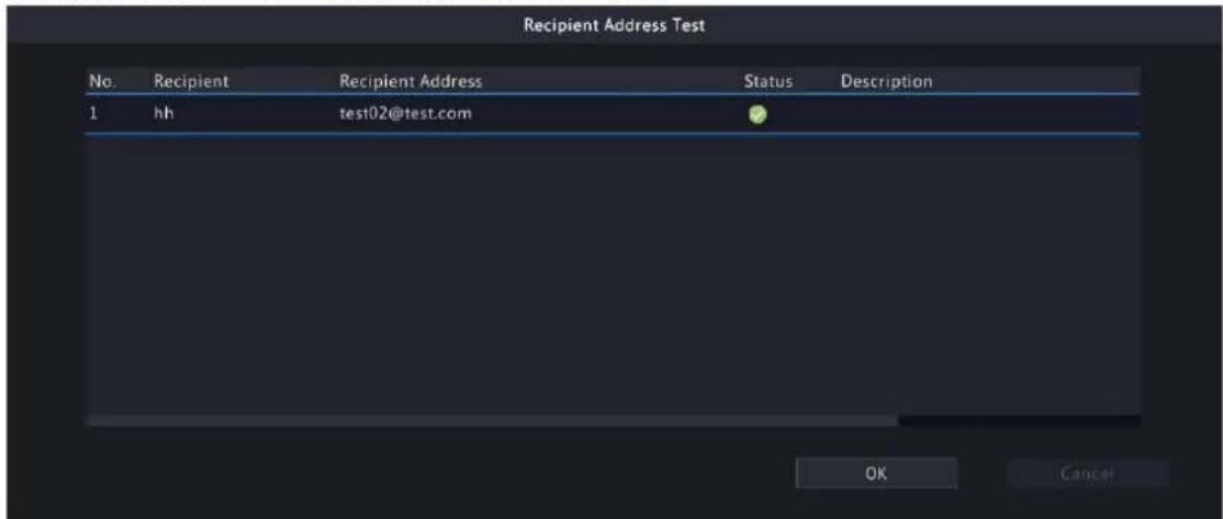
- Click Apply.
7.2 Platform Configuration
Configure an upper platform for the NVR.
7.2.1 SNMP
The NVR can use SNMP to interconnect with the upper platform and transfer certain configuration information.
- Go to Menu > Network > Platform > SNMP.
- Enable SNMP.

- Choose an SNMP type and configure the parameters.
• SNMPv2:
Set the read community name and write community name for the platform to read NVR data.
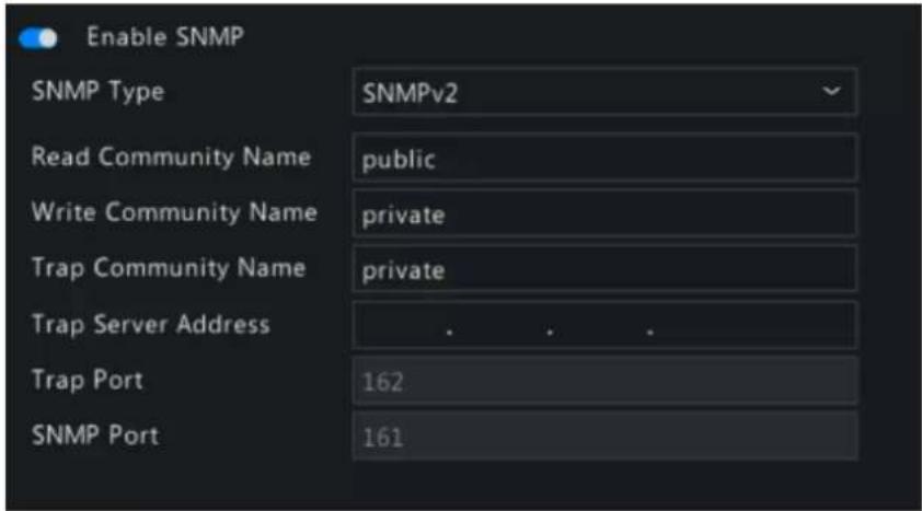
- SNMPv3:
Set authentication password and encryption password. The authentication password is used by the platform to access the NVR. The encryption password is used to encrypt data sent from the NVR to the platform.

- Click Apply.
7.2.2 Alarm Service
Configure an upper server to receive alarms and images from the NVR.
- Go to Menu > Network > Platform > Alarm Service.
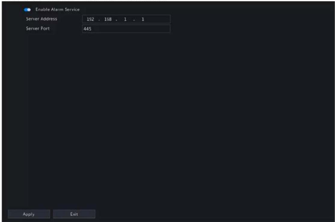
- Enable alarm service.
- Configure the parameters.
| Parameter Description |
| Server Address Upper server's IP address. |
| Server Port Upper server's port number. |

Note: This configuration only enables the sending of alarm-related packets to the alarm host. The specific alarm methods on the alarm host need to be configured separately.
- Click Apply.
7.2.3 Configure VIID Local
Configure VIID local settings so the NVR can monitor vehicles and upload vehicle information to the upper platform.
- Go to Menu > Network > Platform > Video&Image Database Local.
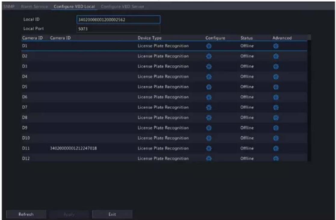
- The local ID and local port use the default settings by default.
- Choose a camera, click under Configure, and then configure the parameters.

| Parameter Description | |
| Camera ID Used for connecting the IP device. | |
| Device Type Divided into | two types by usage:License plate recognition: Usually installed on road checkpoints to capture license plates of passing vehicles.Collection device: Used to capture faces or plates. |
- Choose a camera, click under Advanced, and then configure the parameters.

| Parameter Description | |
| Longitude Longitude of the region where the IP device is located (-180,180). | |
| Latitude Latitude of the region where the IP device is located (-90,90). | |
| Administrative Division Code Administrative division code of the region where the IP device is installed. | |
| Location Location of the IP device. Max 256 characters, allows uppercase and lowercase letters, digits, underscores, and hyphens. | |
| Checkpoint Put into Use Time when the camera was put into use. | |
| Checkpoint Type Choose the actual checkpoint type of the IP device. | |
| Checkpoint Usage Choose the usage of the IP device. | |
| Checkpoint Lanes Number of lanes monitored by the IP device. | |
| Authority Code Organization code of the IP device. | |
- Click Apply.
7.2.4 Configure VIID Server
Configure the VIID server so the NVR can upload face and plate information to the upper VIID platform.
-
Go to Menu > Network > Platform > Video&Image Database Server.
-
Enable video&image database server.
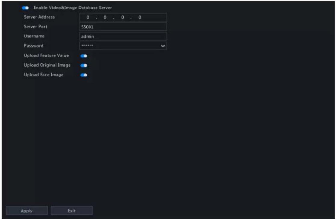
- Configure server parameters.
| Parameter Description |
| Server Address VIID platform's IP address. |
| Server Port VIID platform's port number. |
| Username Username of the VIID platform. |
| Password Password of the VIID platform. |
| Upload Feature Value When enabled, the NVR will upload feature information of the captured faces or plates to the upper platform. |
| Upload Original Image When enabled, the NVR will upload original images of the captured faces or plates to the upper platform. This feature is enabled by default. |
| Upload Face Image When enabled, the NVR will upload small face images to the upper platform. |
- Click Apply.
7.3 Advanced Configuration
Configure PPPoE, ports, port mapping, multicast, and FTP.
7.3.1 PPPoE
Use Point to Point Protocol over Ethernet (PPPoE) to connect the NVR to network.
- Go to Menu > Network > Advanced > PPPoE.
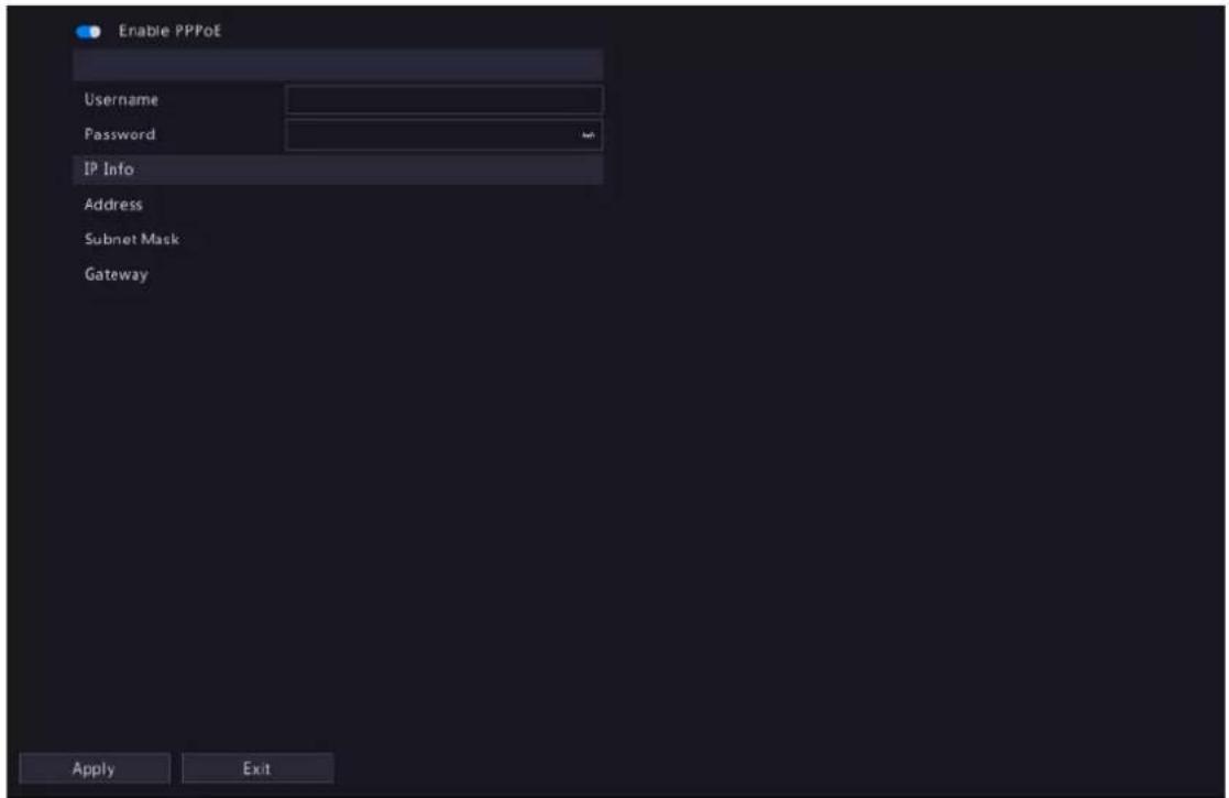
-
Enable PPPoE.
-
Enter the username and password provided by the Internet Service Provider (ISP). IP information is displayed when dial-up succeeds.
Note: For a multi-NIC device, dial-up shall be performed on the NIC that is configured as the default route.
- Click Apply.
7.3.2 Port
Configure HTTP, HTTPS, RTSP, HTTP redirect port, and RTSP redirect port.
- Go to Menu > Network > Advanced > Port.

- Configure the ports.

Note:
- The port range is 1-65535, among which, ports 21, 23, 2000, 3702 and 60000 are reserved for other purposes. Duplicate ports are not allowed.
- The upper platform can access the live video of a camera using the displayed RTSP URL.
3. Click Apply.
7.3.3 Port Mapping
Configure port mapping so client computers can access the NVR on the LAN across the Internet.
- Go to Menu > Network > Advanced > Port Mapping.
- Port mapping is enabled by default. You can choose a mapping mode, UPnP or manual port mapping.
UPnP
UPnP is short for Universal Plug and Play. UPnP-enabled network address translation (NAT) can perform automatic port mapping to enable client computers to access the NVR on the LAN from the Internet.

Note: This function requires router support. You need to enable UPnP on the router before starting configuration on the NVR.
- Choose the UPnP mapping mode.
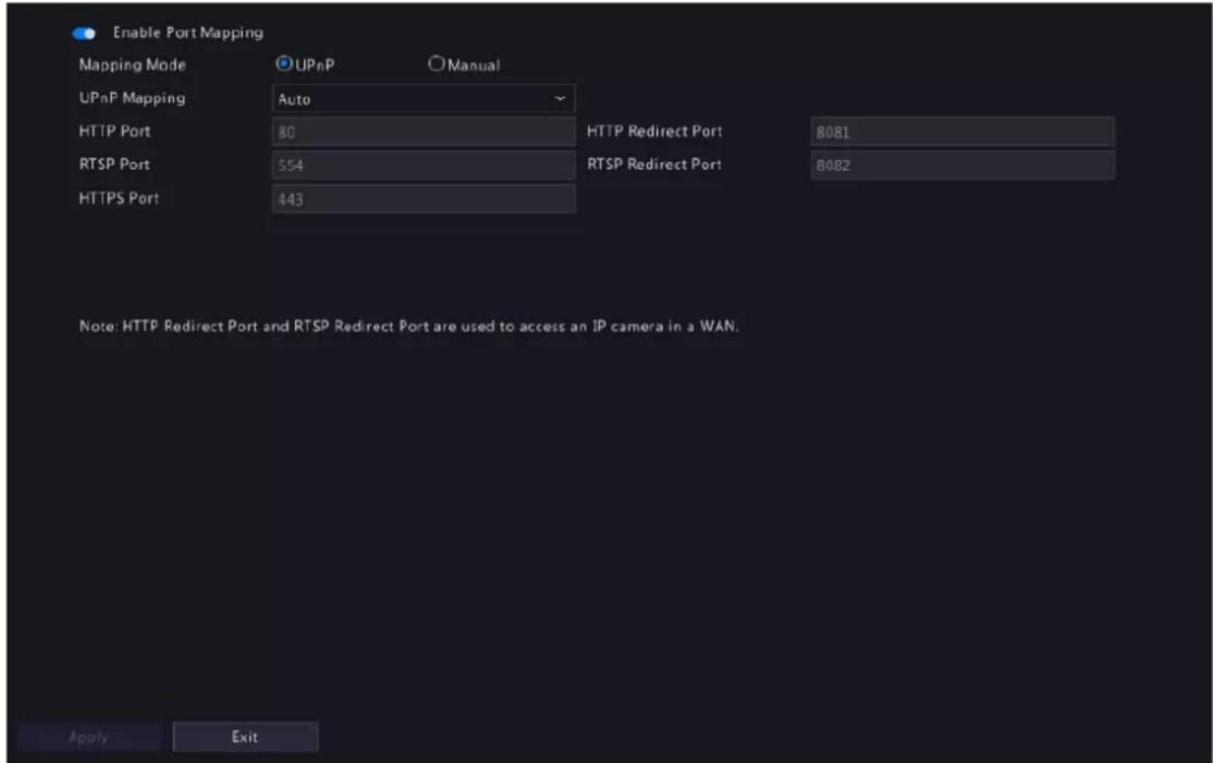
-
Choose a mode from the UPnP Mapping list:
-
Auto: The NVR automatically assigns external port numbers, which are usually the same as the internal port numbers.
- Specify ports: User specifies ports within the range of [1-65535].

Note:
- Auto is recommended. Port conflict may occur when external ports are specified manually.
-
For a multi-NIC NVR, port mapping shall be performed on the NIC that is configured as the default route.
-
Click Refresh, and check whether Active is displayed in the UPnP Status column.
- Click Apply.
Manual
If the router does not support UPnP, you have to configure internal and external ports manually.

Note:
- Make sure the ports configured on the NVR are consistent with that configured on the router.
-
For some routers, the NVR's external and internal ports must be the same, and they also must be the same as the ports on the router.
-
Choose the Manual mapping mode.

-
Set the external ports manually.
-
Click Apply.

Note: After port mapping is configured, you can open the Web interface using the following address: Router's WAN IP:external HTTP port. For example, the router's external IP address is 10.2.2.10, and the external HTTP port is 82, then enter http://10.2.2.10:82 in the Web browser's address bar.
7.3.4 Multicast
When the number of users accessing the Web client has reached the upper limit and live video is unavailable, you can use multicast to solve this issue.
- Go to Menu > Network > Advanced > Multicast.

- Enable multicast, enter the multicast IP address and port number.
- Click Apply.
- Log in to the Web interface, go to Setup > Client, set Live View Protocol to Multicast. Now live view is available through multicast.

Note: Local recordings, snapshots, and downloaded recordings are saved in the Record, Snap, Download folders.
Save

Note:
- IP multicast addresses are class-D addresses. 224.0.1.0 - 238.255.255.255 can be used on the Internet.
- In the range of 224.0.0.0 - 239.255.255.255, some are reserved for special uses, for example, 224.0.0.0 - 244.0.0.255 can only be used on the LAN, where packets with these addresses will not be forwarded by a router; 224.0.0.1 is used by all the hosts on the subnet; 224.0.0.2 is used by all the routers on the subnet; 224.0.0.5 is used by OSPF routers; 224.0.0.13 is used by PIMv2 routers; and 239.0.0.0 - 239.255.255.255 are private addresses (e.g., 192.168.x.x).
7.3.5 FTP
Configure FTP so the NVR can upload images to the FTP server.

Note:
- This feature is only available to certain NVRs.
- To use this feature, you need to deploy an FTP server first.
-
After the FTP server is enabled and connected, the NVR can automatically upload images to the FTP server.
-
Go to Menu > Network > Advanced > FTP.

- Enable FTP.
- Configure server parameters. Click Test to test the connection between the NVR and the FTP server.
| Parameter Description |
| IP Address FTP server address. |
| Port The default is 21. You can set a different port as needed. |
| Anonymous When enabled, the NVR will connect to the FTP server as anonymous user without username/password required. |
| Username Username used to access the FTP server. |
| Password Password used to access the FTP server. |
| Remote Directory Input the remote directory in the correct format (abc/efg/xyz), and the system will create folders level by level accordingly under the root directory, and then create different folders based on IP, time, and channel.Note:For example, if the remote directory is abc, then the created folder is FTP > abc > 206.2.5.8 > 2022-10-08 > D5. If the remote directory is abc/efg/ xyz, then the created folder is FTP > abc efg > xyz > 206.2.5.8 > 2022-10-08 > D5.If the remote directory is empty, the system will create folders under the root directory based on IP, time, and channel, for example, FTP > 206.2.5.8 > 2022-10-08 > D5. |
| Upload Interval(s) The NVR uploads images captured within the set periods to the FTP server at the set interval. The default is 30s. You can alter the setting as needed. |
| Range(s) Show the range of image upload interval: [5-600]s |
- Set an upload schedule.
(1) Choose a camera from the list.
(2) Click 📄 behind Upload Schedule, configure time periods during which the camera will upload images of the desired type(s). Click OK.


Note:
-
Two image upload periods are allowed each day, and the periods must not overlap.
• To apply the schedule to other days, select All or days and then click OK. -
(Optional) To apply the current upload schedule to other cameras, click 📋 behind Copy, select cameras, and then click OK.

- Click Apply.
7.4 Wireless Local Area Network
Plug in a USB wireless network interface card and connect the NVR to the hotspot of a wireless router.
- Go to Menu > Network > WLAN.

-
Click Refresh to refresh the wireless hotspot list.
-
Choose the desired hotspot and then click 📄 connect it.
7.5 Wi-Fi AP
Only Wi-Fi Kit NVR models support this function.
7.5.1 Wi-Fi AP
The IPC and NVR have been paired before leaving factory, and the IPC will be automatically added to the NVR after power-on. However, if the user manually changed one of the parameters and caused any inconsistent parameter between the two, the IPC cannot be added automatically, and pairing is needed.
There are four methods to pair.
One-click pair (if you have a network cable)
- Connect the camera to the switch via a network cable, and connect the switch to the NVR.
- Power on the camera.
- On the NVR's local interface, choose Menu > Network > Wi-Fi AP > Wi-Fi AP.

- Click One-Click Pair, and wait for successful pair within five minutes after the camera is powered on.
Scan code using the camera:
- On the NVR's local interface, choose Menu > Network > Wi-Fi AP > Wi-Fi AP.
- Click QR Code Pair and use the camera to read the QR Code to pair.
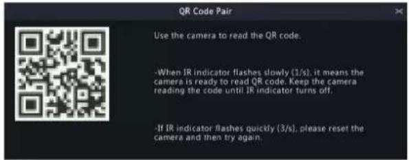
Use the EZView app (if you don't have a network cable)
- On the NVR's local interface, choose Menu > System > Basic, click Wizard, scan the QR code in Step 1 to download and install the EZView app on your mobile phone.
- Connect the mobile phone to the NVR's Wi-Fi.
- Open EZView, tap Settings > Local Config > Device Wi-Fi Configuration, enter the NVR's Wi-Fi name and password.
- Within 10 minutes after the camera is powered on, long-press the IPC's reset button to restore default settings.
- Tap Start on EZView and wait till the IPC is added to the NVR.
Pair manually (if you have a network cable)
Log in to the IPC's web interface. On the Wi-Fi configuration page, fill in the NVR's SSID and password.

- When long-distance transmission or IPC needs to transmit across the wall, the IPC can be dragged, connected to another IPC, and then connected to the NVR by cascading.
- (Optional) Click Help to view the detailed instruction.

- Click Apply to save the configuration.
8 System Configuration
This chapter describes how to configure the system parameters.
8.1 General Configuration
Configure device basic information, time display mode, DST, time synchronization mode, and holidays.
8.1.1 Basic Configuration
Configure the basic information of the system.
- Go to Menu > System > General > Basic Setup.
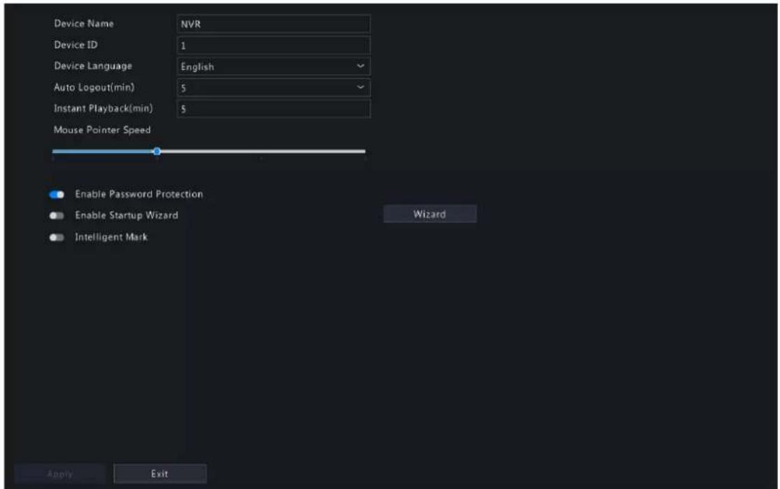
- Configure the basic parameters.
| Parameter Description | |
| Device Name The default name is the NVR model. You can change it as needed. | |
| Device ID Used to distinguish devices if you have more than one device. You can change it as needed. | |
| Device Language Choose the system language. The system will restart after you change the system language.Note: Not all devices can switch the language. | |
| Auto Logout(min) If you are not on the live view page and don't perform any operation, you will log out automatically when the set time is over, and the live view page will be displayed.Default: 5 minutes. You can change it as needed. | |
| Instant Playback (min) Set the instant playback time. Default: 5 minutes. | |
| Mouse Pointer Speed Drag the slider to adjust the speed (left to right: slow to fast). | |
| Enable Password Protection | When the auto logout time is over, the user needs to enter the login password in order to access the main menu.This feature is enabled by default.Note: Only admin can change the setting. |
| Enable Startup Wizard Startup wizard appears when the NVR starts up for the first time. When enabled, the startup wizard appears every time the device starts up. You may click Wizard to set wizard on the Menu page. | |
| Intelligent Mark When enabled, smart detection rules will be displayed on the live video, or smart detection objects will be marked, and the corresponding smart data will be displayed. Smart rules are yellow detection boxes or detection lines.Detection boxes have two colors with different meaning as described below:Green: Data have changed but didn't trigger the rules.Red: Data in the area have triggered the rules configured for the VCA alarm and a VCA alarm has occurred.Note: Some smart functions do not support this feature. | |
- Click Apply.
8.1.2 Time Configuration
Configure the time format and update method.

Note: If the device's battery is low, the following message will appear on the screen: Device time error. Please replace the button battery on the motherboard and reset the time.
Basic Time Config
Go to Menu > System > General > Time. Choose the time zone, date, and time format as needed.

System Time
- Set the system time manually.
- Select the sync mode from the drop-down list, and then the system time will be updated based on the set mode. It is Disable Sync by default.
| Sync Mode Description | |
| Sync with NTP Server The system time will be synced from the NTP server. Configure parameters below as needed.Time Sync Mode Sync with NTP ServerNTP Server Address 172.20.212.80NTP Port 123Update Interval 10m | |
| Sync with Cloud Server The system time will be synced from the Cloud server. To use this function, enable EZCloud first. | |
8.1.3 DST
Configure DST.
- Go to Menu > System > General > DST.

- Enable DST.
- Configure the parameters.
- Click Apply.
8.1.4 Camera Time Synchronization
When Sync Camera Time is enabled, the NVR syncs time to the connected cameras regularly.
This feature is enabled by default.

Note:
- Time sync occurs when a camera goes online for the first time.
-
If Sync Camera Time is enabled, time sync occurs every 30 minutes.
-
Go to Menu > System > General > Time Sync.

Sync Camera Time
- Enable/disable this feature as needed.
- Click Apply.
8.1.5 Holiday Configuration
Configure special time periods as holidays for use in recording schedules.
- Go to Menu > System > General > Holiday.

- Click Add in the lower-right corner.

- Configure the parameters.
| Parameter Description | |
| Holiday Name Set a meaningful and easy-to-remember holiday name. | |
| Status The new holiday is enabled by default. If you want to disable it, select Disable. | |
| Repeat • No: The holiday is effective once only in the specified year. Specify a year for the holiday.• Yes: The holiday is effective every year. | |
| Mode • By Day: Set the holiday in the specified format: year/month/day.• By Week: Set the holiday in the specified format: year/month/week/day of the week. | |
| Start Time/End Time Set according to the specified format. | |
-
Click Apply.
-
Click OK.
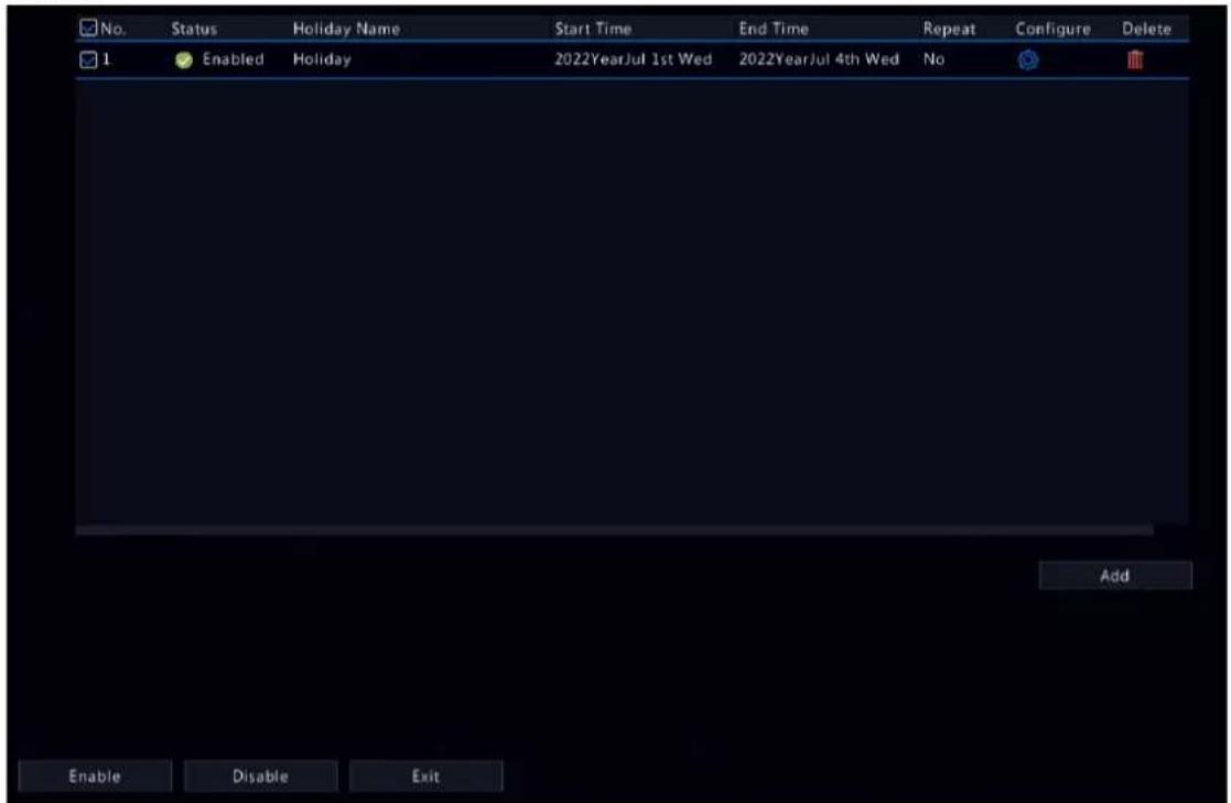
- Click to edit the current holiday.
- Click the delete a holiday. Deleting a holiday will not delete the relevant recordings.
- Click Disable to disable the holiday.
8.2 Preview Configuration
Configure the screen display and preferred stream type for preview.
8.2.1 Preview Configuration
Configure the basic preview parameters and display mode.
Go to Menu > System > Preview > Preview.

Basic Preview Configuration
| Parameter Description | |
| Video Output Outputs the system display to an external display device. Choose an output port.Note: The NVR provides three output ports (VGA, HDMI1/HDMI2, BNC) and can output the system display to three displays simultaneously for independent operations. The actual port types available may vary with device. | |
| Resolution The resolution includes the display format and refresh rate. The display format refers to the number of pixels that can be displayed on the screen, for example, 1920x1080, 1280x720, 1280x1024, etc. More pixels displayed means higher image quality. The refresh rate can be 60Hz, 50Hz, 25Hz, etc. Choose an option that best fits your needs. | |
Preview Windows Displays images in the desired window layout. Choose an option from the list, or click an icon to choose the layout. | |
| Max. Alarm-Triggered Live View Windows | Three options: 1/4/9 windows. SeePreviewfor more information. |
| Enable Sequence Enable sequence. SeeSequencefor more information. | |
| Sequence Interval(sec) Set the sequence interval time. Default: 8 seconds. | |
| Display Camera No. in Preview Windows | When enabled, camera IDs will be displayed in live view windows. This feature is enabled by default. |
Screen Configuration
By default, camera IDs correspond to live view windows: D1 to window 1, D2 to window 2, and so on. You can change the correspondence relationship as follows. The example below shows how to switch D1 and D2.

Note: You may also drag an image on the live view page to swap windows, and then view the changed window-channel binding relationship on this page. But this method requires the Configure permission, and it cannot switch windows that are not on the same screen.
- Click window 1 on the right side. Window 1 is selected.
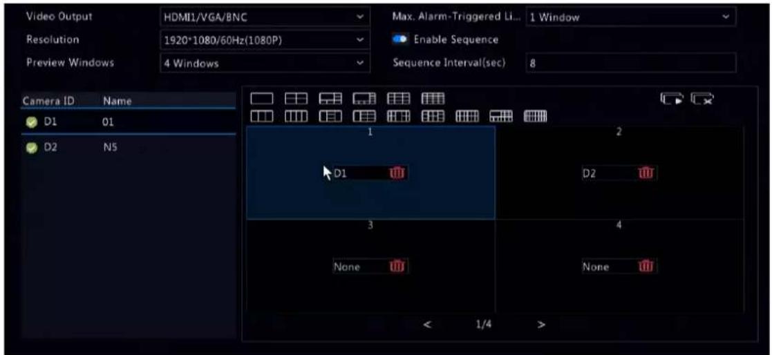
- Click D2 on the left-side channel list. Now window 1 shows D2, and window 2 shows None.

Note: On the left-side channel list, is empty for D1, which means the channel is not bound to any window.
- Click window 2 on the right side. Window 2 is selected.

- Click D1 on the left-side channel list. Now window 2 shows D1, which means D1 and D2 have switched windows with each other.
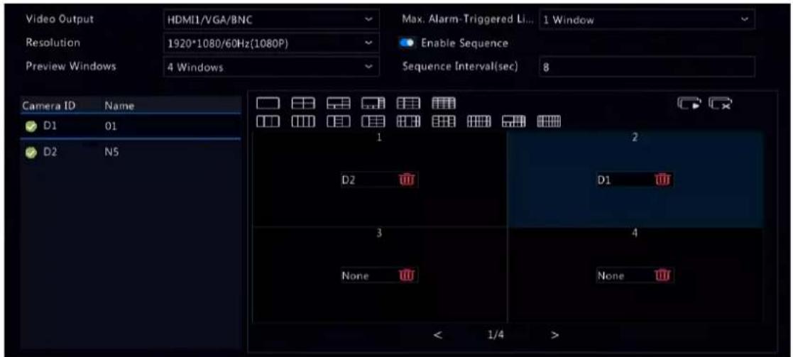
- Click Apply.
8.2.2 Advanced Configuration
- Go to Menu > System > Preview > Advanced.

-
Enable Sub Stream First.
-
Click Apply.
8.3 POS Configuration
Overlay transaction information to live and recorded videos for check and audit.
POS configuration includes POS OSD Configuration and POS Configuration. After the configuration is completed, POS information will be displayed on both live and recorded videos, and POS recordings can be retrieved for playback.
8.3.1 POS OSD Configuration
Configure POS OSD parameters.
- Go to Menu > System > POS > POS OSD.
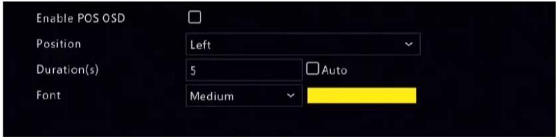
-
Select Enable POS OSD.
-
Configure the parameters.
| Parameter Description | |
| Position POS OSD position. | • Left: In the upper-left corner of the image.• Center: In the middle of the image.• Right: In the upper-right corner of the image. |
| Duration(s) Length of time that POS OSD is displayed on live and recorded video images. Default: 5s. Max. 120s. | |
| Auto Displays POS OSD according to the POS data duration obtained based on Time Start Identifier and Time End Identifier. For Time Start Identifier and Time End Identifier, see also POS Configuration. | |
| Font Font size and color of | POS OSD. Font sizes include X-large, Large, Medium, and Small. |
- Click OK.
8.3.2 POS Configuration
Add POS and configure POS protocols.
- Go to Menu > System > POS > POS.

- Click Add.
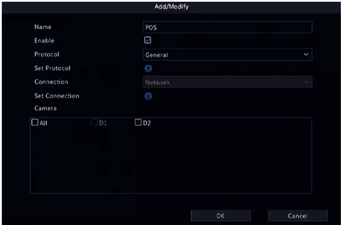
- Configure the parameters.
| Parameter Description | |
| Name Set a name that is easy to recognize. The POS name must be unique. | |
| Enable The new POS is enabled by default. You may clear the checkbox to disable the POS, and enable it on the POS page at any time. | |
| Protocol | General: The POS is directly connected to the NVR.Note: Choose this option with caution. POS connection may fail due to different protocols of different POS machine vendors.AVE: The POS machine transmits data to the AVE device, and the AVE device connects to the NVR.Note: AVE is a device that supports multiple POS protocols. It integrates POS data in different formats and converts them into data transmittable via TCP/UDP. |
| Only applicable to the General protocol. Click the start identifier, end identifier, and line delimiter must be converted into hexadecimal values using Notepad+ before being entered.Start Identifier: (Optional) The NVR starts receiving POS data from the start identifier.Stop Identifier: (Optional) The NVR stops receiving POS data at the received stop identifier.Line Delimiter: (Optional) The NVR inserts a line break into POS data at the line delimiter. | |
| Ignore Characters: (Optional) The NVR displays ignored POS data as*.Time Start Identifier: (Optional) Start time of POS data.Time End Identifier: (Optional) End time of POS data. | |
| Set Connection | Transmission protocols include TCP and UDP. Transaction data are sent to the NVR via TCP or UDP. |
| Local Receiving Port: Port that the NVR uses to receive data. Set an unused port. | |
| Source IPv4 Address: IP address that the POS machine uses to send data. | |
| Source Port: Port that the POS machine uses to send data. | |
| Destination IPv4 Address: Not required. Address that the NVR uses to forward the received POS data. | |
| Destination Port: Not required. Port that the NVR uses to forward the received POS data. | |
| Timeout: Time that the NVR receives POS data before it stops.Default: 5s. Range: 1-3600s.If a stop identifier is configured, the NVR stops receiving POS data at the stop identifier; if no stop identifier is configured, the NVR stops receiving POS data when the timeout expires. The AVE protocol does not involve start and stop identifiers. Therefore, it is necessary to configure a timeout for the NVR to stop receiving POS data and to display POS information. If no timeout is configured, the NVR does not stop receiving POS data, and POS information cannot be displayed. | |
| Camera Choose the camera to which you want to overlay POS data. | |
- Click OK.

- Click to edit the POS.
- Click delete the POS.
- Click Disable to disable the POS.
8.4 User Configuration
Users are entities that manage and operate the system. A user type is a set of operation permissions. After a user type is assigned to a user, the user has all the permissions defined in the type.
The system supports four user types:
| User Type Description | |
| admin The default super administrator, which has the maximum permissions. The initial password is 123456.Note: Only admin can add or delete users and edit other users' permissions. | |
| default The default reserved user, which cannot be added or deleted, only has live view and two-way audio permissions by default, and can be configured by admin only.Note: If the default user is forbidden to use live view and two-way audio on a camera, the camera will be locked when no user is logged in, and displayed in the corresponding window. By default, the default user can only view live video on the local interface without logging in. | |
| Operator By default, an operator has basic permissions and camera permissions. | |
| Guest By default, a guest only has camera permissions. | |
Go to Menu > System > User.

Add User
- Click Add.

- Configure the parameters. Enter the username, password, choose a user type, enable/disable unlock pattern, and choose permissions.
| Item Description | |
| Username Set a username | as you need. Cannot be empty or include Chinese characters. |
| Password/Confirm Set a strong password. | |
| Pattern | To enable the unlock pattern, select the checkbox. Click and then follow on-screen instructions to set a pattern. |
| Basic Permissions/Smart Permissions | Select the permissions you want to assign to the user. |
- Click OK.
Delete User
- On the User page, select the user you want to delete.
- Click confirmation message appears.
- Click Yes.
Edit User
- On the User page, select the user you want to edit.
- Click enter the password.

- Edit the user type, password, or permissions.
- Click OK.
8.5 Security Configuration
Security configuration includes IP address filtering, Onvif authentication, 802.1x, ARP protection, watermark, and secure password.
8.5.1 IP Address Filtering
IP address filtering can ensure only certain source IP addresses can be used to access the NVR's web interface.
- Go to Menu > System > Security > IP Address Filtering.

- Enable IP address filtering.
- Configure the parameters.
| Parameter Description | |
| Control Type Blocklist: Access is forbidden if the IP is on the blocklist. | |
| Allowlist: Access is allowed only when the IP is on the allowlist. If Allowlist is selected but is empty, remote access will be forbidden. | |
| Start IP/End IP Enter the start and end IP addresses. If you want to add only one IP address, enter it in the Start IP field. | |
- Click Add.
8.5.2 ONVIF Authentication
When Onvif authentication is enabled, a username and password will be required to access the NVR via Onvif. This feature is enabled by default. Go to Menu > System > Security > ONVIF Auth.

Enable Authentication
Note: If enabled, a username and password will be required for access by ONVIF.
8.5.3 802.1x
802.1X can prevent unauthenticated devices from accessing the local area network.

Note:
- Only some NVRs support this function.
- You need to configure and enable this function on the network switch first.
-
For multi-NIC devices, this feature will be disabled automatically if you change the NIC's working mode.
-
Go to Menu > System > Security > 802.1x.

- Choose the NIC. Skip this step if the device has only one NIC.
- Enable Configure 802.1x.
- Configure the parameters.
| Parameter Description | |
| Protocol Default: EAP-MD5. | |
| EAPOL Version | Choose 1 or 2. It must be the same version configured on the network switch. |
| Username/Password Must | be the username and password configured on the network switch. |
- Click Apply.
8.5.4 ARP Protection
The Address Resolution Protocol (ARP) dynamically maps an IP address to a MAC address. In a local area network, ARP is necessary for devices to communicate with each other through MAC addresses. ARP attacks exploit ARP vulnerabilities to forge IP addresses and MAC addresses. ARP protection can bind the gateway's IP address and an MAC address to prevent ARP spoofing.

Note: For multi-NIC devices, this feature will be disabled automatically if you change the NIC's working mode. For information about changing the working mode, see Network Configuration.
- Go to Menu > System > Security > ARP Protection.

- Choose the NIC. Skip this step if the device only has one NIC.
- Enable ARP protection.
- Configure the parameters.
| Parameter Description | |
| Gateway | Gateway you have configured in Menu > Network > Basic > Network . |
| Custom: Enter the gateway's physical address in the network switch.Gateway MA | |
| Auto: Automatically obtains the gateway's physical address in the network switch. |
- Click Apply.
8.5.5 Watermark
Use the watermark function to encrypt custom information into video contents to prevent video tampering.
- Go to Menu > System > Security > Watermark.

- Choose the channel, and enable watermark.
- Enter the watermark contents.
- Click Apply.
8.5.6 Secure Password
Secure password specifies application ranges of strong and weak passwords in different password modes. Secure password is divided into two password modes: friendly password and enhanced password.

Note: Only admin can change the setting.
- Go to Menu > System > Security > Secure Password.

-
Choose whether to enable the Enhanced Password mode. The default is Friendly Password.
-
Friendly Password: In this mode, a strong password is required except when the PC client is in the same network segment as the NVR or in one of the three private network segments (10.0.0.0/8, 172.16.0.0/12, 192.168.0.0/24).
• Enhanced Password:
In this mode, the system prompts user to set a strong password if the current password is weak. Also, only strong passwords can be set for new users: At least 9 characters long, and include all three types: letters, digits, and special characters. -
Click Apply.
8.6 Advanced
Configure other items, including serial port, hot spare, and unit.
8.6.1 Serial Port
Configure serial port parameters to connect a keyboard. The serial port settings configured on the NVR must match the serial port settings on the keyboard.
- Go to Menu > System > Advanced > Serial.
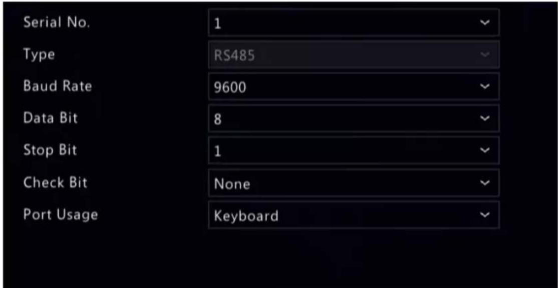
- Configure the parameters.
| Parameter Description | |
| Serial No. Choose the serial port ID. The number of serial ports available may vary with device. | |
| Type Currently only RS485 is available. | |
| Baud Rate Data transmission speed (unit: bits per second). The greater the value, the faster the transmission speed, and the shorter the transmission distance. Usually the default value is used. | |
| Data Bit The actual number of data bits in a data packet. Usually the default value is used. | |
| Stop Bit Indicates the end of a unit of transmission. Usually the default value is used. | |
| Check Bit Used to check whether the received data bits are erroneous. Choose Odd, Even, or None (default) as needed. | |
| Port Usage Keyboard. | |
3. Click Apply.
8.6.2 Hot Spare
When one of multiple working NVRs failed, the hot spare takes over to replace the faulty one. When the faulty NVR recovered, it takes over the hot spare, and the hot spare transfers data stored during the downtime back to the recovered NVR to ensure reliable and uninterrupted data storage.
Go to Menu > System > Advanced > Hot Spare.
Normal Mode
On the NVR to be used as a working device, perform the steps to add a hot spare:
- Click Custom Add.
- Add a hot spare. You can enter the IP of the hot spare manually or search the network segment. The steps are similar to the steps described in Add IPC.
- Click Exit to return to the Hot Spare page to complete the setup.
Hot Spare Mode
On the NVR to be used as the hot spare, perform the steps:
- Go to Menu > System > Advanced > Hot Spare.
- Select the Hot Spare mode.
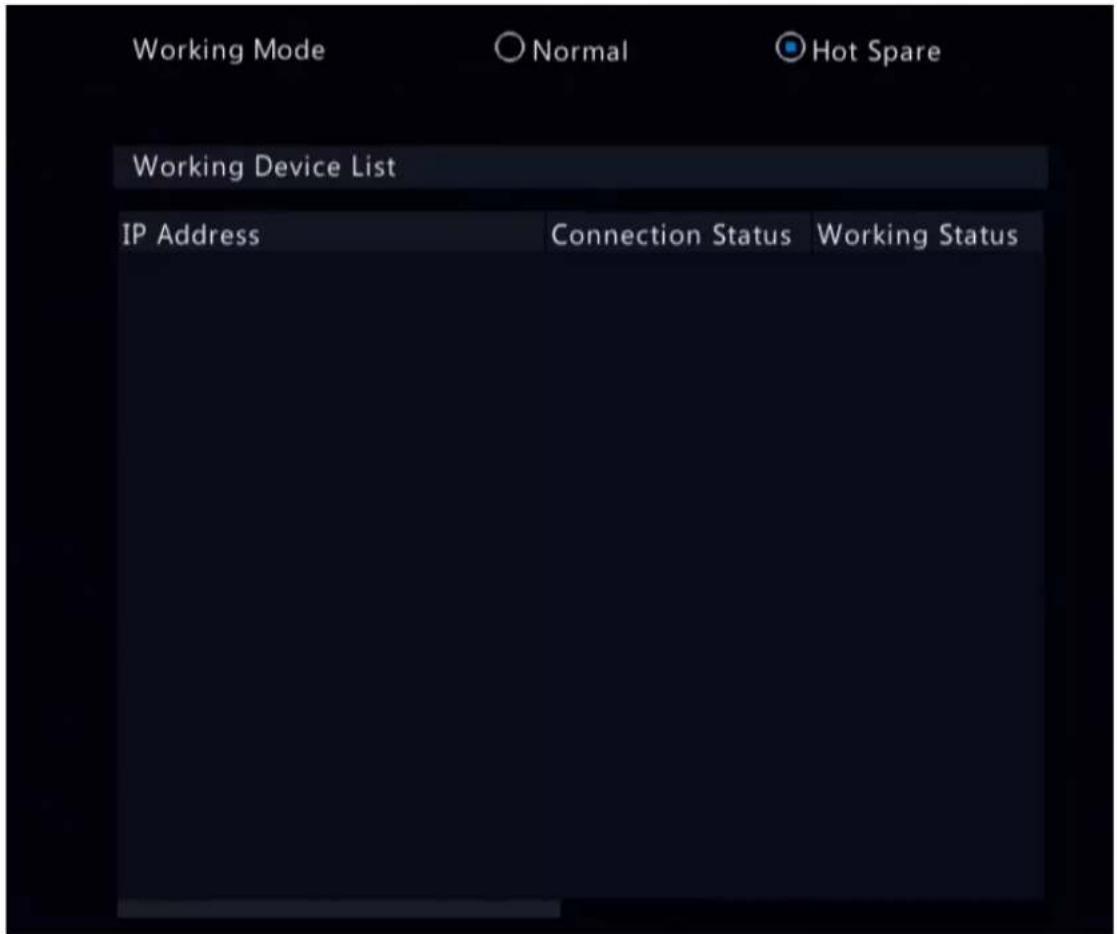

Note:
- Switching the working mode will restart the device. After the device is restarted, some of its parameters will change.
- After a working device is switched to a hot spare, some of its functions are unavailable, and some of its parameters are restored to the default settings.
- If multiple NVRs fail simultaneously, only one can be replaced by the hot spare; the rest wait for backup.
8.6.3 Unit
Configure the temperature unit.
- Go to Menu > System > Advanced > Unit.

-
Choose a temperature unit, including Celsius(°C) and Fahrenheit(°F).
-
Click Apply.
9 Storage
Configure disk storage parameters.
You can configure the storage mode under Camera > Audio & Video > Encoding.

Note: The device uses hard disks to store data, and the hard disks need to be formatted; otherwise, data storage function will be unavailable or affected. A message will alert you if there is no hard disk or any hard disk unformatted.
9.1 Recording Schedule
Make a recording schedule.
A 24/7 normal recording schedule is enabled by default. You can modify the schedule by drawing or editing as needed.
Go to Menu > Storage > Recording Schedule. Select the camera for which you want to make a recording schedule.

Draw a Schedule
- Select a recording type.

heatmap
| Day | 0 | 2 | 4 | 6 | 8 | 10 | 12 | 14 | 16 | 18 | 20 | 22 | 24 | |---|---|---|---|---|---|---|---|---|---|---|---|---|---| | Mon | Normal | Normal | Normal | Normal | Normal | Normal | Normal | Normal | Normal | Normal | Normal | Normal | Normal | | Tue | Normal | Normal | Normal | Normal | Normal | Normal | Normal | Normal | Normal | Normal | Normal | Normal | Normal | | Wed | Normal | Normal | Normal | Normal | Normal | Normal | Normal | Normal | Normal | Normal | Normal | Normal | Normal | | Thu | Normal | Normal | Normal | Normal | Normal | Normal | Normal | Normal | Normal | Normal | Normal | Normal | Normal | | Fri | Normal | Normal | Normal | Normal | Normal | Normal | Normal | Normal | Normal | Normal | Normal | Normal | Normal | | Sat | Normal | Normal | Normal | Normal | Normal | Normal | Normal | Normal | Normal | Normal | Normal | Normal | Normal | | Sun | Normal | Normal | Normal | Normal | Normal | Normal | Normal | Normal | Normal | Normal | Normal | Normal | Normal | | Holiday | Normal | Normal | Normal | Normal | Normal | Normal | Normal | Normal | Normal | Normal | Normal | Normal | Normal | Note: Up to 8 periods are allowed for each day.)| Recording Type Description | |
| Normal Records video during specified time periods. | |
| Event Records video in the event of an event-triggered alarm. | |
| Motion Records video in the event of motion. | |
| Alarm Records video in the event of alarm input. Configure Alarm Input first before making an alarm schedule. | |
| M and A Records video when motion and alarm input occur simultaneously. | |
| M or A Records video when motion or alarm input occurs. | |
| None No recording schedule. | |
- Drag on the time schedule to specify time periods for the recording type. The figure below shows a recording schedule with event recording from 18:00 to 24:00 on Monday and Tuesday, and normal recording during the rest of the time.

bar_stacked
| Day | Normal | Event | Motion | Alarm | M and A | M or A | None | |---|---|---|---|---|---|---|---| | Mon | 0 | 0 | 0 | 0 | 0 | 0 | 0 | | Tue | 0 | 18 | 0 | 0 | 0 | 0 | 0 | | Wed | 0 | 0 | 0 | 0 | 0 | 0 | 0 | | Thu | 0 | 0 | 0 | 0 | 0 | 0 | 0 | | Fri | 0 | 0 | 0 | 0 | 0 | 0 | 0 | | Sat | 0 | 0 | 0 | 0 | 0 | 0 | 0 | | Sun | 0 | 0 | 0 | 0 | 0 | 0 | 0 | | Holiday | 0 | 0 | 0 | 0 | 0 | 0 | 24 | (Note: Up to 8 periods are allowed for each day.)3. Click Apply.
Edit a Schedule
1. Click Edit.
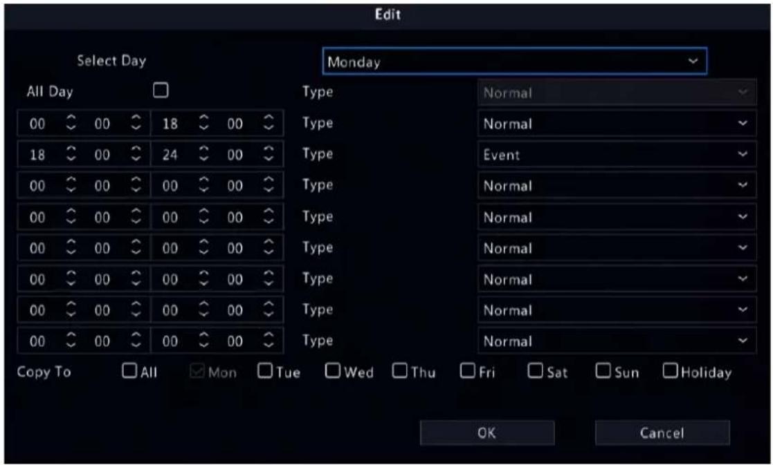
2. Select a day.


Note: Before you select Holiday, go to System > Time > Holiday and complete the holiday settings.
- Clear the All Day check box. As a 24/7 normal recording schedule is enabled by default, you cannot modify the schedule unless All Day is unchecked.
- Set time periods and the corresponding recording types.
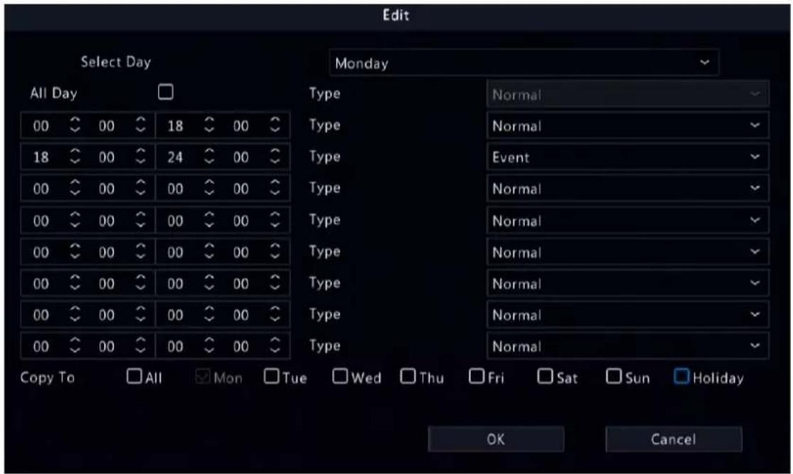
- To apply the same settings to other days, select the desired day(s) after Copy To.
- Click OK.

bar_stacked
| Day | Normal | Event | Motion | Alarm | M and A | M or A | None | |---|---|---|---|---|---|---|---| | Mon | 16 | 18 | 20 | 0 | 0 | 0 | 0 | | Tue | 16 | 18 | 20 | 0 | 0 | 0 | 0 | | Wed | 16 | 18 | 20 | 0 | 0 | 0 | 0 | | Thu | 16 | 18 | 20 | 0 | 0 | 0 | 0 | | Fri | 16 | 18 | 20 | 0 | 0 | 0 | 0 | | Sat | 16 | 18 | 20 | 0 | 0 | 0 | 0 | | Sun | 16 | 18 | 20 | 0 | 0 | 0 | 0 | | Holiday | 16 | 18 | 20 | 0 | 0 | 0 | 0 | (Note: Click a color on the right and then draw the schedule.)- Click Apply.
Other Settings
| Item Description | |
| Pre-Record The duration of | video to be recorded before an alarm. The default value is 10s. |
| Post-Record The duration of | video to be recorded after an alarm. The default value is 60s. |
| Enable Redundant Recording | Recording backup, stores recorded videos to redundant disks synchronously to prevent video loss in case of read/write disk failure. You need to configure at least one redundant disk before enabling redundant recording. See Disk Management for details. |
| Audio Storage Set whether | to record audio. Audio is not recorded by default. |
9.2 Snapshot Schedule
Configure snapshot schedule and snapshot type.
9.2.1 Configure Snapshot Schedule
Make a snapshot schedule.
- Go to Menu > Storage > Snapshot Schedule > Configure Snapshot Schedule.
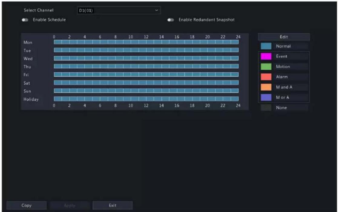
- Select the camera for which you want to make a snapshot schedule.
- Enable schedule.
- Set the snapshot schedule. See Draw a Schedule and Edit a Schedule.
| Snapshot Type Description | |
| Normal Captures images during specified time periods. | |
| Event Captures images in the event of an event-triggered alarm. | |
| Motion Captures images in the event of motion. | |
| Alarm Captures images in the event of alarm input. Configure Alarm Input first before making an alarm schedule. | |
| M and A Captures images when motion and alarm input occur simultaneously. | |
| M or A Captures images when motion or alarm input occurs. | |
| None No snapshot schedule. | |
- Click Apply.
Other Settings
| Item Description | |
| Enable Redundant Snapshot | Snapshot backup, stores snapshots to redundant disks synchronously to prevent snapshot loss in case of read/write disk failure. You need to configure at least one redundant disk before enabling redundant snapshot. SeeDisk Managementfor details.Note:A redundant disk can be used for both recording backup and snapshot backup. |
9.2.2 Snapshot Type
Configure snapshot parameters.
- Go to Menu > Storage > Snapshot Schedule > Snapshot Type.

- Select the camera and set the parameters as needed.
| Item Description | |
| Snapshot Type Supports scheduled snapshot and event-triggered snapshot. You need set image quality and snapshot interval for them respectively. · Schedule: A snapshot is taken according to the set schedule. · Event: A snapshot is triggered by an event such as alarm input and motion detection alarm. Manual snapshots are event-triggered snapshots. | |
| Resolution The number of pixels in a frame. Only certain NVRs support setting resolution. | |
| Image Quality Set the snapshot quality. High, medium, or low are available. | |
| Snapshot Interval Select the time interval between two snapshots from the drop-down list. | |
-
(Optional) To apply the same settings to other cameras, click Copy and select the desired camera(s).
-
Click Apply.
9.3 Array
Configure RAID (Redundant Arrays of Independent Disks) to improve disk read/write efficiency and data security.

Note:
- RAID is only available on certain models, and the RAID types supported may vary with NVR model.
- Cannot create a RAID with local disks and disks in an expansion enclosure at the time.
• NAS and eSATA disks cannot be used to create arrays.
Currently 7 RAID types are supported: RAID 0, RAID 1, RAID 5, RAID 6, RAID 10, RAID 50 and RAID 60. The number of disks available to create different RAID arrays varies depending on the number of disks equipped with the device. See the table below for details.

Note: The number of disks listed in the table below does not include global hot spare disks.
| RAID Type Number of Disks | |
| RAID 0 2 to 8 | |
| RAID 1 2 | |
| RAID 5 3 to 8 | |
| RAID 6 4 to 8 | |
| RAID 10 4 to 16 (must be an integer multiple of 2) | |
| RAID 50 6 to 16 | |
| RAID 60 8 to 16 | |
Before array configuration, enable RAID as follows:
- Go to Menu > Storage > Array.
- Select the Open RAID check box and click Yes in the pop-up dialog box.
Automatically Create an Array
Quickly create an array with one click.
- Go to Menu > Storage > Array > Physical Disk.

- Click One-Click Create, then the system automatically completes array creation based on the number of available disks.
| Number of Disks Available | RAID Type |
| 2 RAID 1 | |
| ≥3 RAID 5 | If there are 4 or more disks available, a global hot spare disk will be created automatically.Note:A global hot spare disk can automatically replace a failed disk in any RAID array to ensure stable array operation. |
- A message appears to prompt you the creation result. Click OK to complete the creation. Check the created array under the Array tab.

Manually Create an Array
Manually create a desired array. Take RAID 50 as an example.

Note:
- To avoid wasting disk resources, please make sure all disks are used to create arrays. Disks that are not used to create arrays are unusable.
- No global hot spare disk will be created automatically if you create arrays manually. To ensure successful automatic array rebuilding and stable system operation, it is recommended to set a global hot spare disk.
-
The capacity of the global hot spare disk must not be less than that of the smallest disk in the array.
-
Go to Menu > Storage > Array > Physical Disk.
- (Optional) Select a disk and click to set it as a hot spare disk.
Note: If there are multiple arrays and you require highly stable arrays, you can configure multiple global hot spare disks. When multiple arrays degrade, the global hot spare disks are used to rebuild them in order of disk number. However, too many global hot spare disks may cause waste of disk resources, so please set them as required.
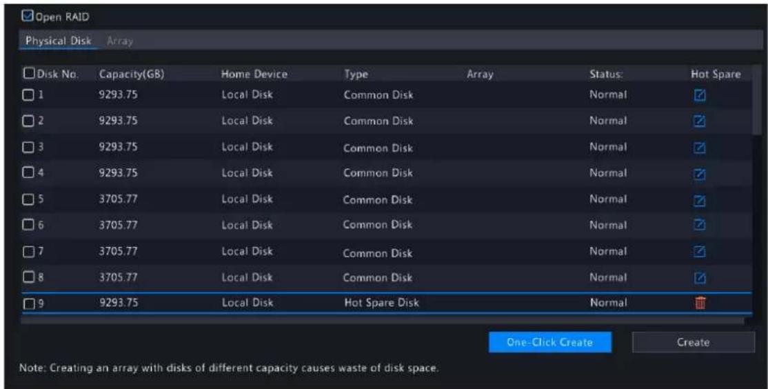
- Click Create.

- Enter the array name and select the RAID 50 type.
- Select the number of sub-array disks.
Note: This parameter is only available to RAID 50 and RAID 60 due to different array creation principles. For example, RAID 50 is a combination of RAID 5 and RAID 0, and RAID 5 is the sub-array of it.
| Type Number of Sub-array Disks Number of Disks Required | |
| RAID 50 3 to 8 An integer multiple of the number of sub- | array disks. RAID 50 requires at least 6 disks. |
| RAID 60 4 to 8 An integer multiple of the number of sub- | array disks. RAID 60 requires at least 8 disks. |
- Click OK. Check the created array under the Array tab.
Rebuild an Array
An array is in one of three states: Normal, Degraded, and Damaged. You can maintain disks in time by checking the disk status to take advantage of the disk array and ensure the security and reliability of data storage.
Note: To be alerted when an array is degraded or damaged, you can configure alarm-triggered actions under Menu > Alarm > Alert.
Go to Menu > Storage > Array > Array.
| Array Status Description | |
| Normal The array is functional. | |
| Damaged The number of physical disks lost exceeds the allowable limit for this type of array and the lost disks cannot be rebuilt. | |
| Degraded A state between Normal and Damaged. | |
Note: For example, in a RAID 5 array with 4 disks, the array is in Degraded state when 1 disk is lost, and in Damaged state when 2 disks are lost.
• Automatically Rebuild an Array
A degraded array can be automatically rebuilt in ten minutes if a global hot spare disk is available and the capacity of the global hot spare disk is not less than that of the smallest disk in the array.

Note: After rebuilding, replace the failed disk in time and set the replaced disk as a global hot spare to ensure the stable operation of the array. See Manually Rebuild an Array for details.
• Manually Rebuild an Array
A degraded array can only be rebuilt manually if no global hot spare disk is available.

Note: Before you start, check if there is an available physical disk. If no, you need to replace the failed disk.
- Go to Menu > Storage > Array > Array.
- Select the array to be rebuilt and click

- Select the rebuild mode and local disk. The Quick rebuild mode takes less time than the Normal rebuild mode, but may result in data loss. Please select with caution.
- Click Apply.
Delete an Array
Deleting an array will erase all data stored on it. Please handle with caution.
- Go to Menu > Storage > Array > Array.
- Click 📋 for the array you want to delete. A confirmation message appears. Click Yes to confirm the deletion.
9.4 Disk Management
Configure disk usage and property, add external disks, and format disks.

Note:
- Before you start, make sure all disks are installed properly.
- Only admin can format disks and configure the disk property.
Go to Menu > Storage > Hard Disk.

Configure the Disk Usage and Property
- Click the disk to edit.
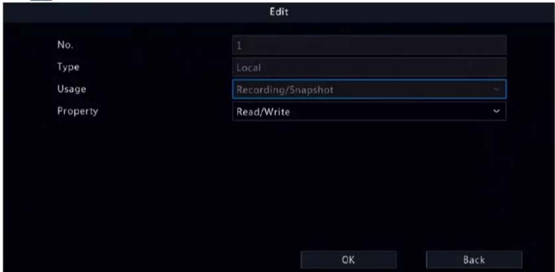
- Select the usage and property. You can only configure the usage of NAS and eSATA.
| Usage Description | |
| Recording/Snapshot Used to automatically store recordings or snapshots. | |
| Backup Used to manually back up device related files, such as recordings/snapshots, logs, configuration information, etc. | |
| Property Description | |
| Read/Write The disk supports recording/snapshot storage, recording playback and snapshot retrieval. | |
| Read Only The disk only supports recording playback and snapshot retrieval, and does not support recording/snapshot storage. | |
| Redundant Recordings and snapshots are saved to read/write disks and redundant disks simultaneously.Note:To view recordings and snapshots on a redundant disk, you need to change the disk property to Read Only. | |
3. Click OK.
Add an External Disk
You can add external disks to the device, including NAS, eSATA, and disk enclosure. eSATA disks and disk enclosures are automatically added when connected to the device. The following describes how to add a NAS.
- Click Add. The Add Extended Disk page appears.
- Select a protocol, and configure parameters.
• NFS: Used to add NAS servers to the LAN.
Enter the NAS server address and directory (a folder path where the NAS server store videos and images).

- SMB/CIFS: Used to add NAS servers to the public network for security. Enter the NAS server address, directory, username, and password.
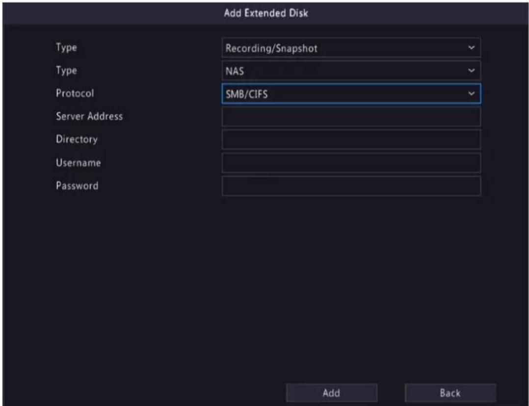

Note:
- Before use, make sure that the NAS server supports SMB/CIFS protocol and has enabled UPnP, or the ports 445 and 139 have been mapped manually on the router.
- A domain name is allowed for the server address if the NAS domain name resolution is available.
3. Click Add.
Format a Disk
Formatting a disk will erase all data stored on it. Please handle with caution.
- Select the disk you want to format.
- Click Format.
- A confirmation message appears.
- Local disk: Click Yes.
- External disk: Select the files you want to format.
Other Operations
Click /- to unmount/mount an eSATA disk.
9.5 Disk Group
You can group disks and allocate a disk group for videos and images from a specified camera to meet the different storage duration requirements of cameras. Different arrays can be assigned to different disk groups. See Space Allocation for details.

Note:
- Redundant disks cannot be assigned to any disk group.
-
Disk group information will be initialized if any disk in the group is formatted.
-
Go to Menu > Storage > Disk Group.
- Enable disk group.

- Click

- Select a disk group for the disk.
- Click Apply.
9.6 Space Allocation
Allocate storage space for videos and images from a specified camera.
- Go to Menu > Storage > Allocate Space.

- Select a camera, select a disk group for storage by the camera, and allocate storage space for videos and images from this camera on the disk group.
| Space Type Description | |
| Recording Space Used to store first stream videos, smart snapshots, POS data, people flow data, and heat map images.Note: First stream video:If theStorage Modeis set toMain and Sub Stream or Main and Third Stream,the first stream is the main stream.If theStorage Modeis set toSub and Third Stream,the first stream is the sub stream. | |
| Image Space Used to store common snapshots, such as snapshots captured by schedule or manually. | |
-
Click Apply.
-
(Optional) Click Copy to apply the same settings to other camera(s).
9.7 Advanced Settings
Configure the storage policy when the storage is full.
- Go to Menu > Storage > Advanced.

- Select whether to overwrite the existing data or stop storage when the storage is full.
| When HDD Full Description | |
| Overwrite The disk space is | divided into allocated space and remaining space according to whether the disk is used for storage by cameras.If a camera is not allocated storage space, it will use the remaining disk space, and its oldest data will be overwritten when the remaining space is used up.Note: As the remaining disk space is variable and older recordings may be overwritten due to insufficient storage space, please allocate storage space with caution. For example, on a device with 20G disk capacity and two cameras, if camera 1 is allocated 10G, camera 2 will use the remaining 10G if it is not allocated storage space. In this case, you can view the last 5 days of recordings from camera 2. However, if you add a new camera to the device, there will be less storage space available to camera 2, and fewer days of recordings can be viewed.If a camera is allocated storage space, its oldest data will be overwritten when the allocated space is used up. |
| Stop This option is only effective to cameras that have been allocated storage space.When enabled, if the allocated space of a camera is used up, new recordings/ snapshots will not be saved. | |
10 Alarm Configuration
Set alarm rules and alarm-triggered actions so as to alert users when an alarm occurs.
10.1 Motion Detection
Motion detection detects motions in specified grids on the image. An alarm is reported when detection rules are triggered.

Note: The parameter may vary with NVR model.
- Go to Menu > Alarm > Motion > Motion Detection.
- Select the desired camera, and enable motion detection.
- Select the detection mode: Motion or Ultra Motion Detection.
Motion Alarm
Motion detection detects motions in specified grids on the image. An alarm is reported when detection rules are triggered.
- Select the detection mode as Motion.
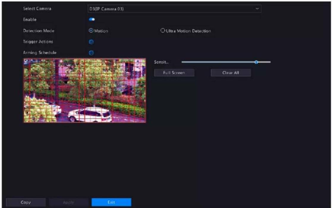
-
Set the detection area. The default is the full screen. You can adjust grid detection areas as needed.
-
To erase grids, click or drag on grid areas.
- To redraw grids, click Clear All, and then click or drag on blank areas to draw grids.
• To detect the full screen, click Full Screen.
Note: When a moving object is detected, the grids where the object appears on the left-side image are filled by .
- Drag the slider to adjust detection sensitivity. The higher the sensitivity, the more likely small motions will be detected, and the more likely false alarms will occur. Set based on the scene and your actual needs.
- Set the alarm-triggered actions and arming schedule. Click the corresponding 📷 to go to the Trigger Actions page and Arming Schedule page respectively. See Alarm-triggered Actions and Arming Schedule for details.
- (Optional) To apply the same settings to other cameras, click Copy and select the desired parameter(s) and camera(s).
- Click Apply.
Ultra Motion Detection
Ultra motion detection detects motions in specified grids on the image, and judges that the motion object is human body, motor vehicle or non-motor vehicle. An alarm is reported when detection rules are triggered.
- Select the detection mode as Ultra Motion Detection.
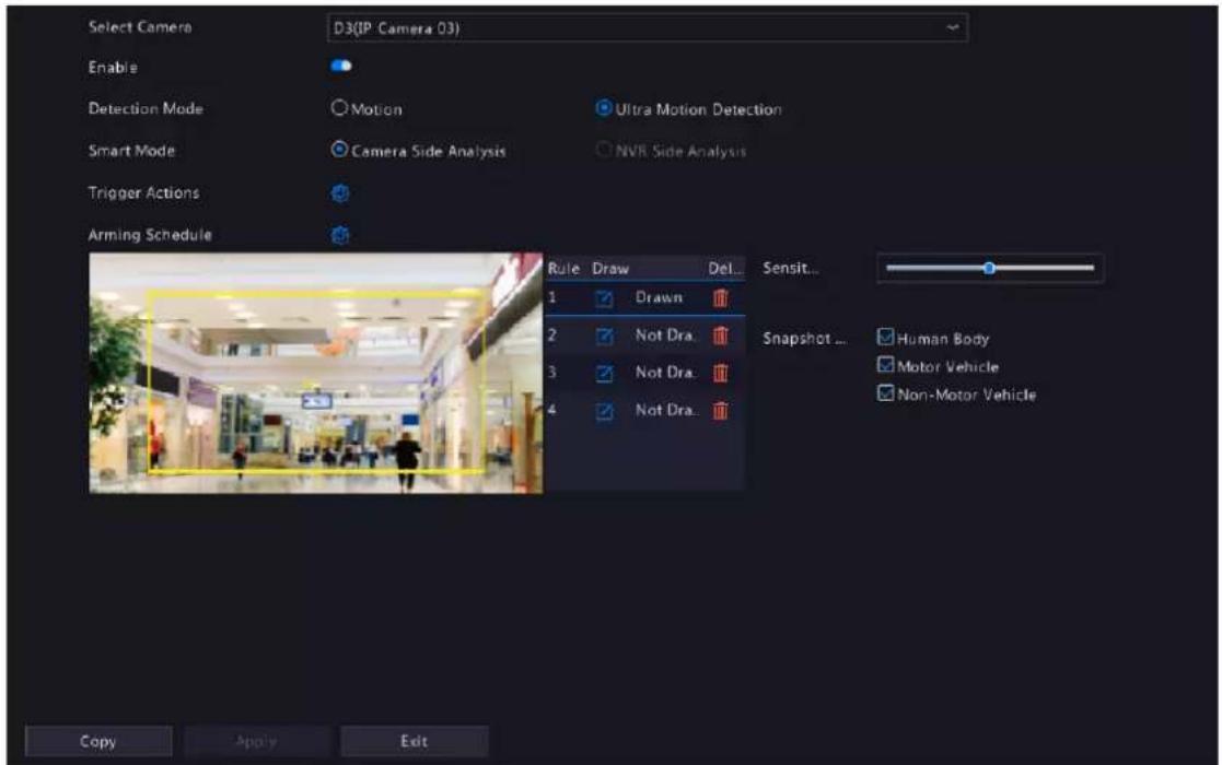
- Select the smart mode, and choose whether to implement this function on the camera side or the NVR side.
- Set detection rules. The 4 detection rules shall be set separately. The following takes Rule 1 as an example.
| Parameter Description | |
| Detection Area | Select Rule 1, click and the full screen is displayed, then draw a detection area.Click on the image and drag to draw a line. Repeat the action to draw more lines to form an enclosed shape as needed. Up to 6 lines are allowed. Right-click to exit the full screen.Note: For a rule in Drawn state, you can click to redraw a detection area. To delete a detection area, click |
| Sensitivity Set the sensitivity by dragging the slider.The higher the sensitivity, the more likely motion behaviors will be detected, but the false alarm rate will increase. | |
| Min. Alarm Interval(s) Set the minimum alarm intervals by dragging the slider. | |
| Snapshot Type | Select the object(s) to be detected, including Human Body, Motor Vehicle and Non-Motor Vehicle. |
- Set the alarm-triggered actions and arming schedule. Click the corresponding 📷 to go to the Trigger Actions page and Arming Schedule page respectively. See Alarm-triggered Actions and Arming Schedule for details.
- (Optional) To apply the same settings to other cameras, click Copy and select the desired parameter(s) and camera(s).
- Click Apply.
10.2 Tampering Detection
Tampering detection detects live video tampering. An alarm is reported when detection rules are triggered.
- Go to Menu > Alarm > Tampering.

- Select the desired channel, and enable tampering detection. The tampering detection area is the full screen by default and cannot be edited.
- Drag the slider to adjust detection sensitivity. The higher the sensitivity, the higher the detection rate, and the higher the false alarm rate. Set based on the scene and your actual needs.
- Set the alarm-triggered actions and arming schedule. Click the corresponding 🔒 to go to the Trigger Actions page and Arming Schedule page respectively. See Alarm-triggered Actions and Arming Schedule for details.
- (Optional) To apply the same settings to other cameras, click Copy and select the desired parameter(s) and camera(s).
- Click Apply.
10.3 Human Body Detection
Human body detection detects humans in a specified area. An alarm is reported when the detection rule is triggered.
- Go to Menu > Alarm > Human Body Detection.

- Select the desired channel, and enable human body detection.
- Set the detection rule. Only 1 detection rule is allowed.
Click and the full screen is displayed. Drag in the preview window to draw a rectangular detection area. Only 1 detection area is allowed. Right-click to exit the full screen.

Note: To redraw the detection area, select the set rule, and click Z. To delete the detection area, click

- Drag the slider to adjust detection sensitivity. The higher the sensitivity, the more likely humans will be detected, and the more likely false alarms will occur. Set based on the scene and your actual needs.
-
Set the alarm-triggered actions and arming schedule. Click the corresponding 📷 to go to the Trigger Actions page and Arming Schedule page respectively. See Alarm-triggered Actions and Arming Schedule for details.
-
(Optional) To apply the same settings to other cameras, click Copy and select the desired parameter(s) and camera(s).
-
Click Apply.
10.4 Video Loss
A video loss alarm is reported when the NVR loses video signals from a camera.
- Go to Menu > Alarm > Video Loss.

-
Video loss alarm is enabled by default. To disable video loss alarm for a channel, click , which then changes to
-
Set the alarm-triggered actions and arming schedule. Click the corresponding 📄 to go to the Trigger Actions page and Arming Schedule page respectively. See Alarm-triggered Actions and Arming Schedule for details.
-
(Optional) To apply the same settings to other cameras, click Copy and select the desired parameter(s) and camera(s), and then click OK.
10.5 Alarm Input and Output
Configure alarm input and alarm output.
10.5.1 Alarm Input
Configure the alarm mode, arming schedule, and alarm-triggered actions for external alarm input devices. The external alarm input devices include devices connected to the ALARM IN interfaces on the NVR and the ALARM IN interfaces on the cameras. For example, access control devices.
- Go to Menu > Alarm > Input/Output > Alarm Input.

-
Select the alarm input channel to be set.
-
A<-1: A refers to the ALARM IN interfaces on the NVR, 1 means the first ALARM IN interface. Likewise, A<-2 means the second ALARM IN interface on the NVR. The number of ALARM IN interfaces may vary with NVR model. See the device datasheet for specifications.
-
D <-1: D refers to channels, the number means channel ID. D<-1 means the alarm input device is connected to the ALARM IN interface of the camera whose channel ID is 1. Likewise, D <-2 means the alarm input device is connected to the ALARM IN interface of the camera whose channel ID is 2. The number is not displayed if the camera has no ALARM IN interface.
-
Click to configure alarm input parameters. After configuration, click OK.

| Item Description | |
| Alarm Input Select Enable to enable the alarm input. | |
| Alarm Input Name The default name is the alarm input number. You may rename it as needed. | |
| Alarm Type | This item is applicable when Alarm Input is enabled. The default is N.O..N.O.: Choose this option if the alarm input device is normally closed. The device opens the circuit to input an alarm, triggers the NVR to open the alarm circuit and report an alarm.N.C.: Choose this option if the alarm input device is normally opened. The device closes the circuit to input an alarm, triggers the NVR to close the alarm circuit and report an alarm. |
- (Optional) Set one-key disarming.
(1) To enable one-key disarm, select in the Disarm by Switch column. When enabled, the configured actions will not be triggered when A<-1 reports alarms.
(2) To apply one-key disarming to other channel(s), click in the Linked Channel column, select the desired channel(s) or All, and then click Apply.
-
Set the alarm-triggered actions and arming schedule. Click the corresponding 🔒 to go to the Trigger Actions page and Arming Schedule page respectively. See Alarm-triggered Actions and Arming Schedule for details.
-
(Optional) To apply the alarm input parameters to other cameras, click Copy, and select the desired channel(s) or Copy To, and then click OK.
-
Click Apply.
10.5.2 Alarm Output
Configure the alarm mode and arming schedule for external alarm output devices.
The external alarm output devices include devices connected to the ALARM OUT interfaces on the NVR and the ALARM OUT interfaces on the cameras, such as alarm light and alarm bell.
- Go to Menu > Alarm > Input/Output > Alarm Output.

-
Select the alarm output channel to be set.
-
A>-1: A refers to the ALARM OUT interfaces on the NVR, 1 means the first ALARM OUT interface. A<-2 means the second ALARM OUT interface on the NVR, and so on. The number of ALARM OUT interfaces may vary with NVR model. See the device datasheet for specifications.
-
D >-1: D refers to channels, the number means channel ID. D->1 means the alarm output device is connected to the ALARM OUT interface of the camera whose channel ID is 1. Likewise, D->2 means the alarm output device is connected to the ALARM OUT interface of the camera whose channel ID is 2. The number is not displayed if the camera has no ALARM OUT interface.
-
Click to configure alarm output parameters. After configuration, Click OK.
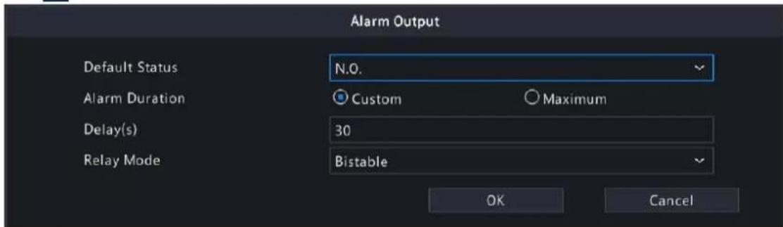
| Item Description | |
| Default Status | Select the default status from the drop-down list. The default is N.O..N.O.: Choose this option if the external device is normally open.N.C.: Choose this option if the external device is normally closed. |
| Alarm Duration/Delay(s) Set | the alarm duration, that is, the length of time that an output alarm lasts after the alarm is ended.Custom: When enabled, you can set the length of time as needed. After an alarm is cleared on the NVR, the third-party alarm device continues alarm till the end of the set duration.Note:The delay period supported by channels may vary. For most channels, the valid range is 5 to 3600s. For certain channels, the valid range is 1 to 3600s.Maximum: When enabled, you cannot set the delay period. The third-party alarm device continues alarm until you clear it manually. |
| Relay Mode Set the relay mode | including monostable and bistable. The default is bistable.Note:Set relay mode to better adapt to third-party alarm devices such as alarm lights. Please set the relay mode according to the trigger mode of the third-party alarm device.Monostable: The circuit can only remain in one stable state. When a trigger pulse is applied, the circuit switches to another state, and then automatically switches back to the original stable state. The circuit will repeat the same actions when the next trigger pulse arrives.Bistable: The circuit can remain in two stable states. When a trigger pulse is applied, the circuit switches to another state, and remains in this state after the trigger pulse is removed. When the next trigger pulse is applied, the circuit switches back to the other stable state and remains in that state. |
-
Set the alarm-triggered actions and arming schedule. Click the corresponding 📋 to go to the Trigger Actions page and Arming Schedule page respectively. See Alarm-triggered Actions and Arming Schedule for details.
-
(Optional) To apply the alarm output parameters to other cameras, click Copy, and select the desired channel(s) or Copy To, and then click OK.
-
Click Apply.
10.6 Thermal Imaging
This function measures body temperature based on infrared imaging, and is suitable for high traffic areas such as hospitals, stations, and shopping malls.

Note: To use this function, please enable face detection in the visible light channel first. To perform face recognition, please enable face comparison at the same time. See Face Detection and Face Comparison for details.
- Add a thermal imaging camera.
(1) Go to Menu > Camera > Camera > Camera.
(2) Click Custom Add to go to the Add IP Camera page.
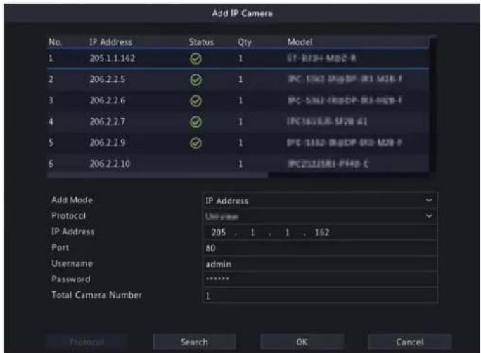
(3) Set the add mode to IP Address, select a protocol, enter the IP address, port, username, and password. There are 2 channels in total, including a visible light channel and an infrared light channel.
- Configure thermal imaging parameters.
(1) Go to Menu > Alarm > Thermal Imaging > Body Temperature Measurement.
(2) Select the infrared light channel, and enable Body Temperature Measurement.

Note: To use this function, please enable face detection first. See Face Detection for details.
(3) Set the black body position. Click enter the full screen, and then drag to draw a bounding box on the image. Right-click to exit the full screen.
Note: The size of the box should be the same as that of the highlighted part of the black body, otherwise measurement results may be affected.
(4) Set the relevant parameters.
| Item Description | |
| Measurement Mode • Measure Internal Temperature: Calculated from the measured body surface temperature by formulas.• Measure Body Surface Temperature: Measured directly by the thermal imaging camera. | |
| Alarm Threshold (30°C~45°C) | An alarm occurs when the measured temperature exceeds the threshold. The default is the normal body temperature of 37.3 °C. |
| Black Body Temperature (-40°C~150°C) | Set the same temperature as the black body temperature. 36 °C is recommended. For more information, refer to the camera's site survey and commissioning guide. |
| Correction Temperature (-10°C~10°C) | Correct temperature measurement errors. Devices have been calibrated before leaving the factory. You do not need to set the correction temperature. If in harsh conditions, such as high or low temperature, youmay configure it according to the camera's site survey and commissioning guide. |
| Environment Temperature (-40°C~100°C) | The environment temperature of the camera will affect the temperature measurement results. The higher the environment temperature, the higher the measurement result. The system can calculate the actual temperature automatically based on the entered environment temperature. 25°C is recommended. |
(5) Set alarm-triggered actions in the Temperature Alarm page. See Temperature Alarm for details.
(6) Click OK.
- View temperature measurement results.
On the preview page, click 📋 on the screen toolbar to go to the Epidemic Control page. Then you can view the detailed information, including counting statistics, live video, realtime data, and history data.

10.7 Temperature Alarm
An alarm occurs when the abnormal body temperature is detected.

Note:
- This function is only available for thermal imaging cameras.
- Before using this function, please enable body temperature measurement on the Temperature Measurement page first. See Thermal Imaging for details.
- Go to Menu > Alarm > Temperature Alarm > Body Temperature Alarm.

- Select the infrared light channel, and enable Abnormal Body Temperature Alarm.
- Set the alarm-triggered actions and arming schedule. Click the corresponding 📄 to go to the Trigger Actions page and Arming Schedule page respectively. See Alarm-triggered Actions and Arming Schedule for details.
- Click OK.
10.8 Alert
Configure alert actions for device abnormal events. The NVR reports an alarm when an event occurs.
- Go to Menu > Alarm > Alert.
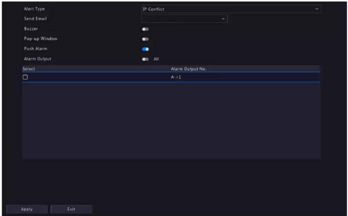
-
Select an alert type from the drop-down list.
-
IP Conflict: IP cameras use the same IP address on the network.
• Network Disconnected: An IP camera is offline. - Disk Offline: No disk or a disk is not properly connected.
• High CPU Temperature: The CPU temperature of the NVR is too high.
• High Motherboard Temperature: The motherboard temperature of the NVR is too high. - Disk Abnormal: A disk is in position but cannot work normally.
- Illegal Access: Incorrect username/password.
- Hard Disk Space Low: The disk space is about to use up.
- Hard Disk Full: The disk space has been used up.
- Array Damaged: The number of lost physical disks in an RAID exceeds the limit.
- Array Degraded: Some physical disks are lost in an RAID but the number of the lost disks is still below the limit.
-
Recording/Snapshot Abnormal: Videos/snapshots cannot be stored normally because the disk is offline or abnormal.
-
Set the alert actions, including buzzer, sending email, and pop-up window. See Alarm-triggered Actions for details.
-
Set the alarm output channel(s). You may enable All, or select specified alarm output channel(s).
-
Click Apply.
-
Repeat the above operations to configure alert actions for other events.
10.9 Audio Detection
Audio detection detects input audio signals. An alarm is reported when an exception is detected. Make sure an audio collection device (e.g. sound pickup) is connected, and audio detection is enabled. See Audio Configuration for details.
- Go to Menu > Alarm > Audio Detection.

- Select the desired channel, and enable audio detection.
- Set the alarm-triggered actions and arming schedule. Click the corresponding 📋 to go to the Trigger Actions page and Arming Schedule page respectively. See Alarm-triggered Actions and Arming Schedule for details.
- Set audio detection rules.
| Item Description |
| Detection Type Select an audio detection type from the drop-down list.Sudden Rise: An alarm occurs when the rise of volume exceeds the set value.Sudden Fall: An alarm occurs when the fall of volume exceeds the set value.Sudden Change: An alarm occurs when the rise or fall of volume exceeds the set value.Threshold: An alarm occurs when the volume exceeds the set threshold. |
| Difference/Threshold Drag the slider to adjust the difference and threshold.The difference between two sound volumes. An alarm occurs when the rise or fall of volume exceeds the difference (range: 0-400). This item is applicable when the detection type is Sudden Rise, Sudden Fall, or Sudden Change.Threshold: The limit value of volume. An alarm occurs when the detected volume exceeds the set value (range: 0-400). This item is applicable when the detection type is Threshold. |
- Click Apply.
10.10 Buzzer
Configure the alarm duration of the buzzer on the NVR.
- Go to Menu > Alarm > Buzzer.

- Set the alarm duration. The default is 30s.
• Maximum: When enabled, you cannot set the alarm duration. When an alarm occurs, the buzzer will alarm continuously until the alarm ends.
- Custom: When enabled, you can set how long the buzzer will alarm after it is triggered. The valid range is from 1 to 600(s). When an alarm occurs, the buzzer will alarm continuously within the alarm duration, and stop automatically if the alarm ends first within the duration.
Note: To stop a buzzer alarm manually, right-click in the preview window, select Manual > Buzzer. See Buzzer for details.
- Click Apply.
10.11 People Present Alarm
An alarm occurs when the number of people present in a specified area exceeds the set threshold.
Note: To use this function, make sure that people flow counting is supported by the camera and is enabled on the VCA page. See People Flow Counting for details.
Configure People Present Alarm
- Go to Menu > Alarm > People Present Alarm.

2. Configure parameters.
| Parameter Description | |
| Select scene Select a scene and set scene information respectively. Up to 4 scenes are allowed. | |
| Scene Name The 4 scenes are named as Scene 1, Scene 2, Scene 3, and Scene 4 by default. You can also customize scene name. | |
| Enable People Present Alarm Enable people present alarm. | |
| Arming Schedule | Click right to Arming Schedule and configure it as needed. See Arming Schedule for details. |
| Select Channel | Click to select desired channel(s) to bind to the scene. |
| People Present Alarm Threshold The maximum number of people allowed in the monitored area.An alarm occurs when the number of people present exceeds the threshold. The valid range is from 1 to 100,000.Number of People for Minor Alarm: Set the number, and click to set Alarm-triggered Actions.Number of People for Major Alarm: Set the number, which must be greater than the number of people for minor alarm, and then click to set Alarm-triggered Actions.Number of People for Critical Alarm: Set the number, which must be greater than the number of people for major alarm, and then click to set Alarm-triggered Actions. | |
- Set the time to clear people counting data. The NVR will clear people counting statistics on the OSD at the set time. This operation does not affect statistics and data reporting.
(1) The initial number of people in scene is 0 by default. You can enable Manual Reset, and set the number as needed.
(2) When Manual Reset is disabled, you can set the auto reset strategy. It can set by day, week, and month.
4. Click Apply.
View Data
On the preview page, select People Flow Counting from the drop-down list in the upper right corner, then you can view the number of people entered, left, and present.

10.12 One-Key Disarming
Cancel alarm-triggered actions of NVRs or IPCs with one click.
- Go to Menu > Alarm > One-Key Disarming.
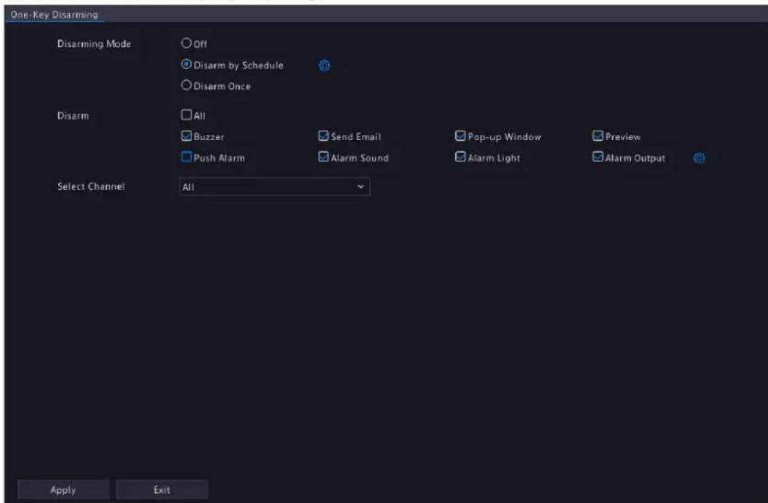
- Select a disarming mode and configure parameters.
• Off: Disarming is disabled.
- Disarm by Schedule: The device is disarmed during specific time periods per week.

(1) Click right to Disarm by Schedule, and set the disarming periods. Click OK to return to the One-Key Disarming page.
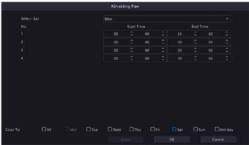

Note:
- Up to 4 disarming periods during one day are allowed.
- To apply the same disarming schedule to other days, select All or the intended day(s), and click OK.
(2) Select actions to be disarmed. The default is all actions. See Alarm-triggered Actions for details.
- Disarm Once: The device is disarmed during a specified time period.
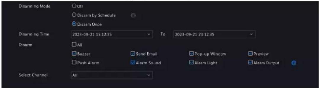
(1) Select Disarm Once, and set the disarming start time and end time.
(2) Select actions to be disarmed. The default is all actions. See Alarm-triggered Actions for details.
3. Click Apply.
10.13 Manual Alarm
Trigger or clear an alarm output manually.

Note: Manual alarm has the highest priority.
Manual Alarm
- Right-click and select Manual > Manual Alarm.
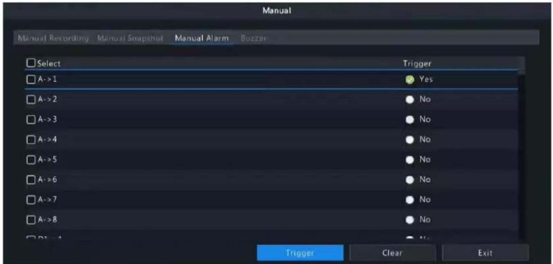
- Trigger or clear alarm(s) manually.
- Trigger: Select the channel(s) to be triggered and click Trigger, and then changes to
- Clear: Select the channel(s) to be cleared and click Clear, and then changes to .
Buzzer
- Right-click and select Manual > Buzzer.

- To stop the buzzer, select the buzzer (in Started status) and then click Stop.
11 System Maintenance
View system operation status to ensure stable system operation.
11.1 System Info
View the basic information and operation status of the device.
11.1.1 Basic Info
View the basic information of the device, including NVR model, firmware version, build date, etc.
- Go to Menu > Maintenance > System Info > Basic Info. View the basic information of the device.

| Parameter Description |
| Model NVR model. |
| Product Configuration Product configuration, which can be the maximum number of channels or product series, for example, 128 means up to 128 cameras can be connected; 8-X means X Series and can connect up to 8 cameras. |
| Serial No. Serial number. |
| Firmware Version Firmware version of the NVR. |
| Build Date Release date of the current firmware version. |
| Operation Time Length of time the NVR has been operating since the latest startup. |
- Scan the QR code to download the app and manage the NVR on a mobile phone.
- Click Privacy Policy to view our privacy policy as needed.
- Click Open Source Notices to view our open source notices as needed.
11.1.2 Camera Status
View camera status information.
Go to Menu > Maintenance > System Info > Camera. View camera information including name, online/offline status, event type and status.
| Camera ID | Camera Name | Status | Motion | Tampering | Video Loss | Audio |
| D1 | D016M2250 | Online | Triggered | Off | On | Off |
| D2 | 400W | Online | On | Off | On | Off |
| D3 | N5 | Online | Triggered | Off | On | Off |
| D4 | N3 | Online | Triggered | Off | On | Off |
| D5 | 2.241 | Online | Triggered | Off | On | Off |
| D6 | 247 | Online | Triggered | Off | On | Off |
| D7 | N5(2.5) | Online | Triggered | Off | On | Off |
| D8 | N5SMD | Online | Triggered | Off | On | Off |
| D9 | N5(2.7) | Online | On | Off | On | Off |
| D10 | N5(2.9) | Online | On | Off | On | Off |
| D11 | D1822247 | Online | Triggered | Off | On | Off |
| D12 | N5(2.11) | Online | On | Off | On | Off |
11.1.3 Recording Status
View the recording status and encoding parameters of the connected cameras.
Go to Menu > Maintenance > System Info > Recording. View recording information including recording type, recording status, diagnosis, and encoding parameters.
| Camera ID | Camera Name | Type | Status | Diagnosis | Stream Type | Frame Rat... Bit Rate(K... Resolution | |
| D1 | D016M2250 | Event | Ongoing | Normal | Main and Third ... 30 | 2006 | 1920X1080 |
| D2 | 400W | Normal | Ongoing | Normal | Main and Sub S... 30 | 3769 | 1920X1080 |
| D3 | N5( 2.50 ) | Event | Ongoing | Normal | Main and Third ... 30 | 1710 | 1920X1080 |
| D4 | N3 | Event | Ongoing | Normal | Main and Third ... 12 | 2030 | 2880X1620 |
| D5 | 2.241 | Event | Ongoing | Normal | Main and Third ... 25 | 4211 | 2880X1620 |
| D6 | 247 | Event | Ongoing | Normal | Main and Third ... 30 | 1522 | 1920X1080 |
| D7 | N5( 2.5 ) | Event | Ongoing | Normal | Main and Third ... 30 | 649 | 1920X1080 |
| D8 | N5SMD | Event | Ongoing | Normal | Main and Third ... 25 | 4056 | 2880X1620 |
| D9 | N5( 2.7 ) | Normal | Ongoing | Normal | Main and Sub S... 20 | 2462 | 2304X1296 |
| D10 | N5( 2.9 ) | Normal | Ongoing | Normal | Main and Third ... 30 | 243 | 1920X1080 |
| D11 | D1822247 | Event | Ongoing | Normal | Main and Third ... 30 | 2678 | 1920X1080 |
| D12 | N5( 2.11 ) | Normal | Ongoing | Normal | Main and Third ... 30 | 2010 | 1920X1080 |
11.1.4 Online User
View the logged-in users, and force non-admin users to log out of the NVR when necessary.
- Go to Menu > Maintenance > System Info > Online User.

- Choose a non-admin user and then click Logout.

Note: Only admin can manage user permissions.
11.1.5 HDD Status
View the status and property of HDDs on the NVR.
Go to Menu > Maintenance > System Info > Disk. View hard disk information including the total capacity, free space, status, manufacturer, and property.

11.1.6 Decoding Card Status
View decoding card status. Only certain NVRs support this function.
Go to Menu > Maintenance > System Info > Slot Status. View the slot type, number of video outputs, and video output status.

11.2 Network Information
View network information including network traffic, network latency, packet loss rate, and network status.
11.2.1 Network Traffic
View network interface card (NIC) information including connection status, physical address, MTU, NIC type, and real-time traffic.
- Go to Menu > Maintenance > Network Info > Network Traffic.

line
| NIC | Connection Status | MAC Address | MTU | NIC Type | |-------|--------------------|-------------|------|----------| | NIC1 | Connected | 6c:f1.7e:85.6e:f2 | 1500 | 1000M Full-Duplex | | NIC2 | Disconnected | 6c:f1.7e:85.6e:f3 | 1500 | 10M Half-Duplex | | NIC3 | Connected | 6c:f1.7e:85.6e:f4 | 1500 | 100M Full-Duplex | | NIC4 | Disconnected | 6c:f1.7e:85.6e:f5 | 1500 | 10M Half-Duplex |- Choose an NIC to view the real-time network traffic.
11.2.2 Packet Capture
Capture, view, and save network packets for network security and troubleshooting.
- Go to Menu > Maintenance > Network Info > Packet Capture.

- Choose a partition to save the captured packets.
-
Specify ports and IPs.
-
All: Capture packets of all the ports and IPs connected to the device.
- Specify: Capture packets of the specified ports and IPs.
-
Filter: Capture packets except that of the specified ports and IPs.
-
Set the packet size. The default is 8192 Bytes, and the range is [0-8192].
-
Click for the NIC to start capturing packets.
Note: A progress bar appears. To cancel the task, click Cancel.
- View the captured data.
When the task is completed, the captured data are saved to the root directory of the USB storage device, and the Backup page appears, showing the file containing the captured packets. You may also click Open to open the Backup page.
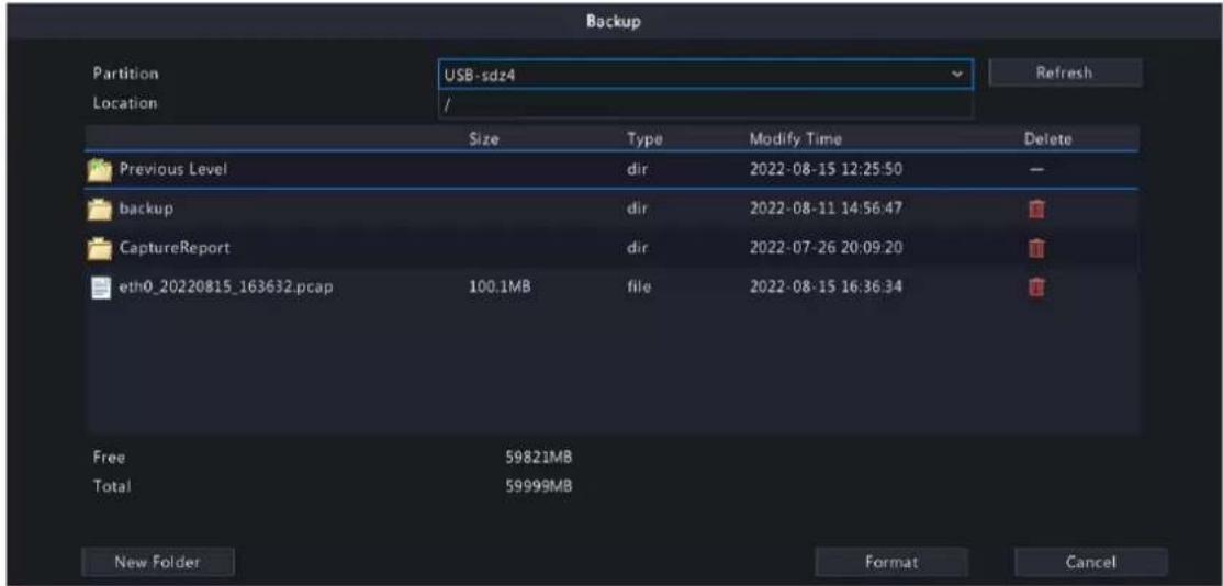
Note:
- The device cannot capture packets if a capturing task is already started on the Web client.
- The file containing the captured packets is named in this format: NIC_YYYYMMDD_hhmmss.pcap, for example, eth0_20220815_163632.pcap.
- When PPPoE dial-up succeeded, a virtual NIC appears in the NIC list. You can also capture packets of the NIC.
11.2.3 Network Check
Monitor the network traffic, network latency, packet loss rate, etc.
Configure Network Check
- Go to Menu > Maintenance > Network Info > Network Check.
- Select the Select Channel checkbox, select the channel(s) you want to monitor. Up to 5 channels are allowed.
- Select the Test Address checkbox, and then enter the address you want to test. You may enter an IP address or a domain name. Up to 2 IP addresses (separated with a semicolon) are allowed.
- Choose the test duration. The system will test the network status during this time. Options are 30s (default), 1 min, 5 min, 10 min, 30 min, and 1 hour.
- Set the size of test packets. The default is 1500 Bytes. The range is [64-4000]. Set according to the actual network condition.

- Click Test to test the packet loss rate and network latency.
View Test Results
If the test is successful, the system saves test data and shows the packet loss rate and network latency. If the test failed, the test result shows "The destination is unreachable".

Note: If you click Stop Test before the test is completed, the system will save the existing test data and show the test result.
- You can click the Currently Displayed drop-down list to choose the channel or address to be tested.
-
Click Packet Loss Rate or Network Latency to view the test result.
-
Packet loss rate
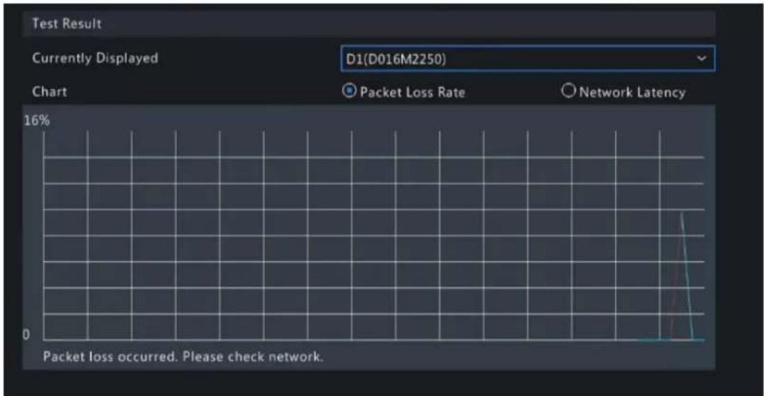
line
| Metric | Value | | ---------------- | ----- | | Packet Loss Rate | 0 | | Network Latency | 0 | | Currently Displayed | D1(D016M2250) | | Packet loss occurred. Please check network. | 0 |- Network latency

line
| Time | Packet Loss Rate | |------|------------------| | 0 | 0 | | 1 | 0 | | 2 | 0 | | 3 | 0 | | 4 | 0 | | 5 | 0 | | 6 | 0 | | 7 | 0 | | 8 | 0 |Export Test Results
- Click Export. The Backup page appears.
- Choose the destination path, click Backup to export test results to the external storage device.
- The exported file is a .tgz package, including ping logs of all the test objects and one summary file. See the examples below.
- Exported files
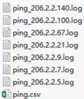
- Exported report
| 1 | Test Item No. | Section 1 | Section 2 | Section 3 | Section 4 | Section 5 | Section 6 | Section 7 | Section 8 | Section 9 | Section 10 | Section 11 | Section 12 | Section 13 |
| 2 | Chl 1. | LossPkt: 0 | AvLossPkt: | LossPkt: | LossPkt: | LossPkt: | LossPkt: | AvgRtt: | 0.561200 ms, TimeNov: | 2022-08-17 13:57:10 | ||||
| 3 | Chl 2. | LossPkt: 0 | AvLossPkt: | LossPkt: | LossPkt: | LossPkt: | LossPkt: | AvgRtt: | 1.199800 ms, TimeNov: | 2022-08-17 13:57:10 | ||||
| 4 | Chl 3. | LossPkt: 0 | AvLossPkt: | LossPkt: | LossPkt: | LossPkt: | LossPkt: | AvgRtt: | 0.546800 ms, TimeNov: | 2022-08-17 13:57:10 | ||||
| 5 | Chl 4. | LossPkt: 0 | AvLossPkt: | LossPkt: | LossPkt: | LossPkt: | LossPkt: | AvgRtt: | 0.710800 ms, TimeNov: | 2022-08-17 13:57:10 | ||||
| 6 | Chl 5. | LossPkt: 0 | AvLossPkt: | LossPkt: | LossPkt: | LossPkt: | LossPkt: | AvgRtt: | 1.064200 ms, TimeNov: | 2022-08-17 13:57:10 | ||||
| 7 | 205.2.2.21. | LossPkt: 0 | AvLossPkt: | LossPkt: | LossPkt: | LossPkt: | LossPkt: | AvgRtt: | 1.099200 ms, TimeNov: | 2022-08-17 13:57:10 | ||||
| 8 | 206.2.2.67. | LossPkt: 0 | AvLossPkt: | LossPkt: | LossPkt: | LossPkt: | LossPkt: | AvgRtt: | 1.223000 ms, TimeNov: | 2022-08-17 13:57:10 | ||||
| 9 | ||||||||||||||
| 10 | ||||||||||||||
| 11 | ||||||||||||||
| 12 | ||||||||||||||
| 13 | ||||||||||||||
| 14 | ||||||||||||||
| 15 | ||||||||||||||
| 16 | ||||||||||||||
| 17 | ||||||||||||||
11.2.4 Network Status
View network parameters of an NIC.
Go to Menu > Maintenance > Network Info > Network. Choose an NIC to view its network parameters.

11.2.5 Network Resource Statistics
View bandwidth usage.
Go to Menu > Maintenance > Network Info > Network Statistics. Bandwidth usage is displayed.
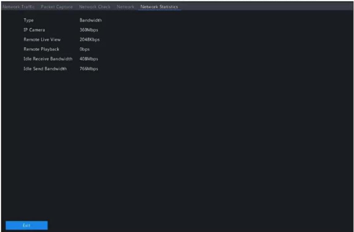

Note:
- When idle receive bandwidth is low, cameras cannot get online.
- When idle send bandwidth is low, live view, playback, and recording download will fail.
11.2.6 PoE and Network Port Status
View connection status of PoE ports or network ports. This function is applicable to NVRs with PoE ports or network ports.
Go to Menu > Maintenance > Network Info > PoE Port Status or Network Port Status. The port connection status is displayed. Blue means the port is in use. For PoE device, you may also view power information.
11.3 Log Search
Logs contain information about user operation and device status. You can use logs to keep track of device operation status and view detailed alarm information.
Log Search
- Go to Menu > Maintenance > Log.
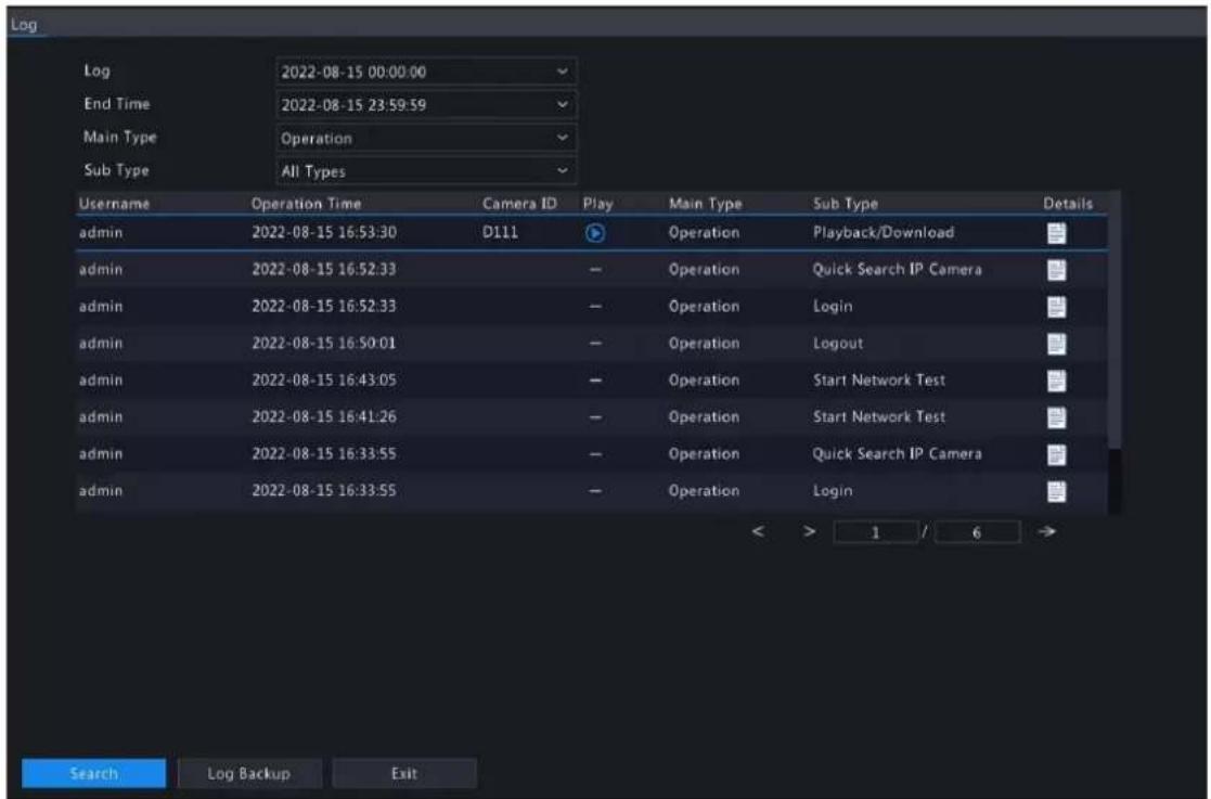
- Set the start time, end time, main type and sub type.
- Click Search.
- Click to view log details.

Playback
Click to view the video recorded at the current log time.
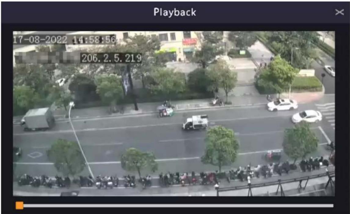

Note:
- This feature is not available to certain log types.
- The video is 11 minutes long (1m before and 10m after alarm).
Log Backup
Click Backup. The Backup page appears. Choose the destination path, click Backup to save the logs to the external storage device.
11.4 Maintenance
11.4.1 Maintenance
Maintenance includes restore system, system backup, and auto-function.
Go to Menu > Maintenance > Maintenance > Maintenance.
Restore System
Restore default system settings.
-
Choose Default or Factory Default as needed. A message appears. The NVR will restart and restore the default settings after you confirm. Choose a method according to your actual needs:
-
Restore: Restore default settings except network settings, user settings, and time settings.
• Factory Default: Restore all default settings. -
Click Apply.

Note: Either option will not delete the recorded videos and operation logs.
System Backup
Import, export, and delete system configurations.
- Click System Backup.
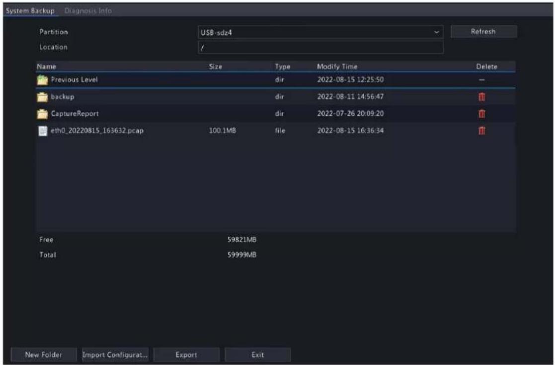
-
Perform the following operations as needed:
-
Import configurations: Choose the *.xml file in the directory list, click Import Configuration, and then confirm to import the configuration file.
- Export configurations: Choose the destination in the directory list, click Export Configuration. Then a *.xml file containing the exported configurations is generated in the specified folder later.

Note:
- Caution: The device will restart after you import configurations. If power is disconnected during the process, the system will be unusable.
- Only admin can import or export configurations.
- Delete: Choose the folder or file to be deleted, click 📄m 🐎ns the folder or file cannot be deleted.

Note: Caution: Deleted files cannot be recovered.
- Create folder: Choose the destination path in the directory list, click New Folder, enter a folder name to create the folder.
- Refresh: Click the Refresh button to refresh the list.
3. Click Apply.
Auto-Function
The device can restart or delete files automatically at the preset time. Only admin can perform this operation.
- Find the Maintenance area.
- Configure the parameters.
- Auto-Restart System: The system restarts automatically at the set time.
- Auto-Delete File(s): The system automatically deletes videos and images saved on the hard disk. Range: 1-240.
3. Click Apply.
11.4.2 Diagnosis Info
View and back up diagnosis information of the NVR and the connected cameras. The NVR keeps 14 days of diagnosis information and overwrites the earliest when the storage is full.
Go to Menu > Maintenance > Maintenance > Diagnosis Info.
NVR Diagnosis Info
- Choose NVR as the device type.
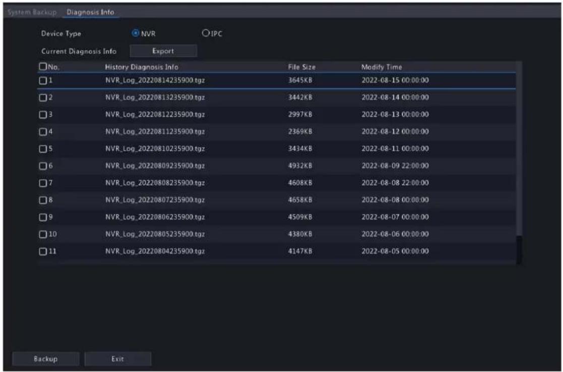
- Export NVR diagnosis information.
- Current Diagnosis Info: Diagnosis information since the latest startup. Click Export to export diagnosis information to the external storage device.
- History Diagnosis Info: All the history diagnosis information in the list. Select the desired item(s), click Backup. On the Backup page, choose the destination path, click Backup.
Camera Diagnosis Info
- Choose IPC as the device type.

-
Choose the desired camera from the list.
-
Export diagnosis information of the selected camera.
- Current Diagnosis Info: Diagnosis information since the latest startup. Click Export to export diagnosis information to the external storage device.
- History Diagnosis Info: All the history diagnosis information in the list. Select the desired item(s), click Backup. On the Backup page, choose the destination path, click Backup.
11.4.3 One-Click Collection
Collect NVR and camera diagnosis information.
- Go to Menu > Maintenance > Maintenance > One-Click Collect.

- Choose the camera and select a number of days of diagnosis information to be collected. NVR diagnosis information is always collected.
- Click Export to collect camera diagnosis information, NVR diagnosis info, and operation logs.
Note: Choose the days according to the actual requirements. The export process may take a long time if you choose All.
11.5 System Upgrade
Upgrade the firmware of the NVR and the connected cameras.
Two upgrade methods are available. The device will restart after the upgrade is completed.
- Cloud upgrade: Upgrade through the cloud server.
- Local upgrade: Upgrade using the upgrade files saved in a USB storage device.
Note:
- Make sure the device is always connected to power and network during the upgrade. Use an Uninterrupted Power Supplies (UPS) if necessary.
- Before you start a cloud upgrade, make sure the DNS server is functional. Go to Menu > Network > Basic > Network. See Network Configuration for detailed information.
- The cloud upgrade speed is limited by the network transmission speed.
11.5.1 NVR Upgrade
Upgrade the firmware of the NVR.
- Go to Menu > Maintenance > System Upgrade > NVR Upgrade.
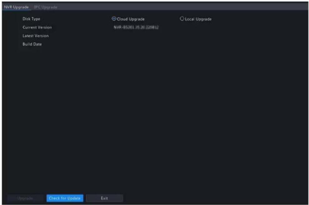
2. Choose Cloud Upgrade or Local Upgrade.
- Cloud Upgrade
Click Check for Update. The system checks for updates.
- If updates are available, the new version number and its build date are displayed. Click Upgrade to start.
- If no updates are available, the system indicates that the current version is already the latest.
- Local Upgrade
Select the upgrade file in the USB storage device, click Upgrade to start.

Note: If the upgrade failed, the failure cause will be displayed, and the device will restart automatically. Fix the problem and then try again.

11.5.2 IPC Upgrade
Upgrade the firmware of the IPC. This function is only applicable to cameras connected via the Private protocol.
1. Go to Menu > Maintenance > System Upgrade > IPC Upgrade.

2. Choose Cloud Upgrade or Local Upgrade.
- Cloud Upgrade
Click Check for Update. The system checks for updates.
- If updates are available, the new version number and its build date are displayed. Click to upgrade a camera, or select multiple cameras and then click Upgrade to upgrade in batches.
- If no updates are available, the system indicates that the current version is already the latest.
- Local Upgrade
(1) Click to upgrade a camera, or select multiple cameras and then click Local Upgrade.
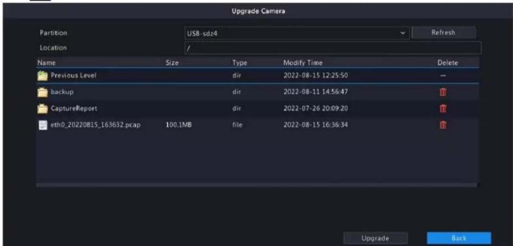
(2) On the Upgrade Camera page, select the upgrade file in the USB storage device, and then click Upgrade.
11.6 HDD Check
Perform S.M.A.R.T. test and bad sector detection. The actual functions available may vary with device.
11.6.1 Run S.M.A.R.T. Test
S.M.A.R.T. tests the hard disk including its head, platter, motor, circuit, etc. and evaluates the disk health status.
- Go to Menu > Maintenance > HDD > Run S.M.A.R.T. Test.

- (Optional) Enable Continue to use the disk when it fails to pass evaluation, so the device can continue using the hard disk even if the disk fails in the self-assessment. However, this may incur great risks. Please choose carefully.
-
Choose the disk slot and test type.
-
Short: Less test contents, faster speed.
- Extended: More comprehensive and thorough, longer time.
-
Conveyance: Detects problems in data transmission.
-
Click Start Test. The Status column shows the real-time progress, for example, Testing: 10%. View test results after the test is completed.
The overall evaluation provides three kind of status: Healthy, Failure, Bad Sectors. It is recommended to replace faulty disks immediately. Contact our technical support for more information.
11.6.2 Bad Sector Detection
The device system detects bad sectors in hard disks in a read-only manner.
- Go to Menu > Maintenance > HDD > Bad Sector Detect.

- Choose the disk slot and detection type.
- Click Start Test. To stop the detection, click Stop Test.

• means the detected area is in good condition.
- means the detected area is damaged. The detection stops automatically when the error count reaches 100.
12 Playback
12.1 Instant Playback
Instant playback plays the video recorded during the last 5 minutes.
Make sure that the video is recorded during the last 5 minutes. Instant playback does not work if there's no recording during this time.
- On the preview page, select the target window, and click on the window toolbar.

natural_image
Highway traffic scene with multiple yellow trucks and cars, no visible text or signage-
Drag the slider on the progress bar to fast forward. Click to pause.
-
Click to exit the playback.
12.2 Normal Playback
Normal playback plays all recordings of the selected camera(s).
-
On the preview page, right-click the desired window and select Playback. The system plays the video of the selected camera. You can also choose other cameras to play videos in this page.
-
You can choose multiple cameras for synchronous playback.
- Click Max. Cameras to select the maximum number of cameras allowed. The performance may vary with NVR model.
- Click Close All to stop playback for all cameras.

- Double-click the desired date, or select the date and then click 📋 to start playback. By default, the system plays the video of the current day.
Note: The calendar uses different flags to indicate different recording types: blue for normal recording, red for event-triggered recording, and no flag for none.
- The NVR plays HD videos by default. You can switch to SD mode if SD videos are stored. The supported video clarity depends on the storage mode, and HD videos are supported by all the storage mode. To store SD videos, go to Menu > Camera > Encoding to set the storage mode. See Encoding Settings for details.

Note:
- If no images are displayed on the preview page in SD mode, it indicates SD videos are not stored.
- If SD video is available in SD playback mode, SD video is played by default; it switches to HD video automatically when you double-click the window to maximize it in a multi-window layout.
Table 12-1: Playback Toolbar
| Button Description | |
 | Show playback progress.Note:indicates 4 cameras are selected.Indicates the playback progress in the first window.Indicates the playback progress in the second window, and so on.Different colors on the progress bar mean different recording types: blue for normal recording, red for event-triggered recording, green for smart event recording. |
 | Timeline.Note:In normal playback mode, hover over the timeline to view a thumbnail image to quickly pinpoint an event. |
 | Zoom in or out on the timeline. Alternatively, click on the timeline and use the scroll wheel to zoom in or out. |
 or , and the corresponding human body motor vehicle, or motor vehicle recordings will be shown green on the progress bar.Note:Select End up each video page will only play recordings of the corresponding object type.This function is only available to the single-channel playback. or , and the corresponding human body motor vehicle, or motor vehicle recordings will be shown green on the progress bar.Note:Select End up each video page will only play recordings of the corresponding object type.This function is only available to the single-channel playback. | |
 | File saved on a USB storage device. |
 | Start/stop clipping video. |
 | Manage files (clips, snapshots, locked files, tags); indicates there is a newly saved file. |
 | Take a snapshot. The window borders will flash white. |
 | Rewind/forward 30s, or choose from the drop-down list. |
 | Reverse. |
 | Stop playback and return to the start point. |
 | Play/pause. |
 | Slow down/speed up.Note:Click restore the normal playback speed after clicking, and vice versa. |
| Button Description | |
 | Forward by frame. |
 | Set the video clarity, including HD or SD. |
 | Enable/disable POS. When enabled, POS OSD appears on the screen, and some toolbar buttons are deactivated.Note:This function is available for certain NVRs.The button only appears in normal playback mode and POS playback mode. In normal playback mode, POS OSD is displayed for 5s. In POS playback mode, the time is configurable. |
 | Full screen. |
| [DSX] | Exit the playback screen. |
 | Click a playback window to show the window toolbar. |
 | Take a snapshot. |
 | Add a tag at the current time point. |
 | Digital zoom. See Digital Zoom for details. |
 | Turn on/off audio. |
 | Adjust the sound volume. |
 | Lock. |
12.3 Smart Playback
In smart playback mode, the system searches smart events in the recording and adjusts the playback speed accordingly. If smart results are detected such as motions, the video plays at normal speed; otherwise, the video plays at 16x speed to save time.

Note:
- This function is available for cameras that support smart functions.
- By default the system searches motion in video.
-
Only one camera can be selected for smart playback.
-
On the playback page, select Smart.

- Select the desired camera.
- Double-click the date you want to play, or select the date and then click to start playback.
- Set smart search rules. The default smart search area is the full screen. To specify a smart search area, follow the steps below.
(1) Click to go to the Smart page.

(2) Click to clear the existing areas, then click and drag on the image to specify an area.
Table 12-2: Smart Search Buttons
| Button Description Button | Description | ||
 | Motion detection: Full screen. |  | Clear the specified areas. |
 | Start search smart playback of the specified areas. |  | Exit theSmartpage. |
| Sensitivity | Adjust detection sensitivity. |
12.4 Corridor Playback
Corridor playback plays recordings in corridor mode in multiple windows. Up to 3 cameras can be selected in corridor mode.
- On the playback page, select Corridor.
- Select the desired cameras you want to play.
- Double-click the desired date, or select the date and then click start playback.

12.5 External File Playback
This function allows you to play recordings stored in an external storage devices such as USB drive or portable hard drive.
- On the playback page, click on the screen toolbar.
- Click Refresh and then wait for the NVR to read the external storage device.
- Double-click the desired recording file, or select the file and then click or to start playback.

12.6 Tag Playback
Use tags to mark specific events in the video for quick location and playback.
Add Tag
- On the playback page, select the desired camera and date, and click to start playback.
- Click anywhere on the image, and then select the pop-up toolbar.

- Enter the tag name. Tag time cannot be edited, which is the time when the tag was added.
- Click OK to save the settings.
Tag Management
The added tags are saved to File Management. To view the newly added tag, click on the screen toolbar.
To rename a tag, click ☑ To delete a tag, click .

Playback by Tag
- On the playback page, click Video Retrieval, select Tag Search from the drop-down list in the upper left corner.

- Select the desired cameras with tags, enter keywords, set the time period, and then click Search.
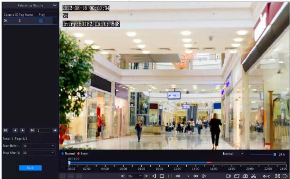
- Double-click the tag you want to play, or select the tag and then click to start playback.
12.7 Playback by Search
This function allows you to search and play recordings by an event type, such as motion detection, human body detection, alarm input, video loss, VCA, tag, POS, and people present alarm.

Note: Before playback, make sure that the alarm and alarm-triggered storage for the event are enabled.
- On the preview window, right-click and select Playback.
- On the playback page, click Video Retrieval, select the type and sub type, and enter keywords.

- Select the desired camera(s) and time period, and then click Search.
- Double-click the result you want to play, or select the result and then click to start playback.
12.8 File Management
File management allows you to manage video clips, tags, snapshots taken during playback, and lock/unlock files.
Video Clip
You may clip and back up videos during playback. See Video Clip Backup for details.
Playback Snapshot
You may take a snapshot during playback and then back up the snapshot. See Playback Snapshot Backup for details.
Locked File
You may lock, unlock, and back up a recording file.
- On the playback page, select the desired camera and date, and click to start playback.
- Drag the slider to play the desired part of the video, click on the image to display the toolbar, and then select

Locking a recording file will prevent all the files stored in the same disk partition (254.4MB in size) from being overwritten.
- Click 📄 the screen toolbar to view the locked file on the Locked File tab.
• To unlock a file, click and then the icon changes to .
- To back up a file, select the file and then click Backup.
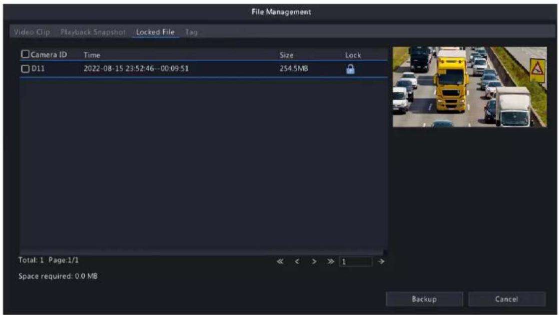
Tag
You may view, edit, or delete tags as needed. See Tag Management for details.
13 Shutdown
This chapter describes device shutdown, logout, and restart.
Shutdown refers to turn off the operating system of the device with power supply connected. Please disconnect the power supply if the device will be shut down for a long time.

- To shut down the NVR, long press the power button on the front panel (if available) for more than 3 seconds till an on-screen message appears, and then click Yes.
- To shut down, log out, or restart the NVR, hover the mouse at the bottom of the preview page to display the screen toolbar, click and then select shut down, log out, or restart as needed.

Note: Unsaved settings will be lost if the NVR is shut down unexpectedly, for example, due to a power failure. A shutdown during a system upgrade may cause startup failures.
You may access and manage the NVR remotely using a web browser on your PC (through the Web interface).
14.1 Preparation
Check the following before you begin:
- Access will be authenticated during login, and operation permissions will be required.
- The NVR is operating properly and has a network connection to the PC.
- A Web browser is installed on the PC. Chrome 60 or later is recommended. Firefox 60 or later, Microsoft Internet Explorer 10.0 or later, Edge 79 or later are also supported.
- The PC uses an operating system of Windows 7 or later.
- A 32-bit or 64-bit Web browser is required if you are using a 64-bit operating system.

Note:
- The parameters that are grayed out on the Web interface cannot be edited. The parameters and values displayed may vary with NVR model.
- The figures below are for illustration purpose only and may vary with NVR model.
14.2 Login
Follow these steps to log in to the Web interface (take IE10 browser as an example).
- Open a Web browser on your PC, enter the IP address of the NVR in the address bar (192.168.1.30 by default), and then press Enter.
- Install the plug-in.
- You need to install the plug-in as prompted at your first login, which is mainly used for processing media streams. Close all the Web browsers when the installation starts. Follow the on-screen instructions to complete the installation and then open the browser again to log in.

Please click here to Download and install the latest plug-in. Close your browser before installation.
- You may also find the plug-in manually by entering HTTP://IP address/ActiveX/Setup.exe in the address bar, and press Enter.
- On the login page, enter the default username and password (admin/123456) and then click Login.


Note: The default password is intended only for your first login. You are strongly recommended to set a strong password to ensure account security.
- Strong password: At least 9 characters including all three elements: letter, special character, and digit.
- Weak password: Less than 9 characters including two or less of the three elements: letter, special character, and digit.
14.3 Live View
The Live View page is displayed when you are logged in. Select the desired channel on the left, and view the live video.
![Live View Playback Setup Smart DIN3 D2 D3 D4 D6 D7 D8 D9 D10 D11 D12 D13 D14 D15 [0fps] [0fps] (0+0) [0.00%] sdmon Legend Preview...](/content/2026/06/1364532/images/cf4cb7ab66f345b126da06288c6999fd9bee45ecf48994ed3ea9db4a1205c67e.jpg)
The operations may vary with NVR model.
Table 14-1: Live View Window Control Buttons
| Button Description Button Description | ||||
| [4E3K] | Two-way audio | Main/sub/third stream | ||
 | Start/stop live video in all windows | Previous/next screen | ||
 | Switch screen layout Select stream type | |||
 | Enable/disable intelligent mark | (25fps) [2.56Mbps] (1920×1088) [H254] (0.59%) | Frame rate/bit rate/resolution/packet loss | |
| [AD30] | Open/close the control panel Take a snapshot | |||
| [DH4C] | Local recording Digital zoom | |||
 | Turn on/off audio | Start/stop two-way audio | ||
 | 3D positioning Full screen | |||
| [03D7] | Multi-sensor preview Fisheye mode | |||

Note:
• right to device name means two-way audio with the NVR. right to channel name means two-way audio with the camera.
- Only the main stream is displayed when the camera is offline or it supports only one stream.
- Snapshots are saved in a snapshot file folder named with the IP address, and snapshot files are named in Camera ID_time format and saved in this directory: \Snap\IP\Camera ID_time. The time is in YYYYMMDDHHMMSSMS format.
- Local recordings are saved in a recording file folder named with the IP address, and recording files are named in Camera ID_S recording start time_E recording end time format and saved in this directory: \Record\IP\Camera ID_S recording start time_E recording end time. The recording start and end times are in YYYYMMDDHHMMSSMS format.
14.4 Playback
Click Playback to go to the Playback page. You can select the playback type, clarity, and camera to view recorded videos.
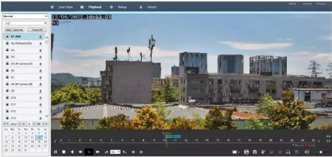
Table 14-2: Playback Control Buttons
| Button Description | Button Description | ||
 | Play/pause Stop |  | |
 | Reverse |  | Slow down/speed up |
 | Rewind/forward 30s. You can change the time as needed. |  | Rewind/forward by frame |
 | Set the display ratio, including full or original |  | Take a snapshot |
 | Start/stop clipping video Save video |  | |
 | Enable/disable digital zoom Add a cl n tag | ||
 | Zoom in/out on the timeline Adjust |  | off sound |
 | Previous/next period | ||
14.5 Configuration
Click Setup on the top, and set the relevant parameters.

14.6 Smart
Click Smart on the top, and configure the relevant parameters. See VCA Configuration for details.

15 Appendix FAQ
| Problem Possible Cause and Solution | |
| Forgot the login password. | Click Forgot Password on the login page as admin, then follow the on-screen instructions to retrieve password. |
| Cannot load the Web plugin. • Close your web browsers when the installation starts. | |
| No images are displayed in live view on the Web interface. | Check if the bit rate is 0Mbps in the live view window. |
| • If yes, check if the firewall/anti-virus program is disabled on your PC. | |
| ·If not, check if the graphics card driver on your PC is working properly. Try installing the driver again. | |
| A camera is offline, and No Link is displayed. | Click Menu > Maintenance > System Info > Camera. The cause is displayed under Status. Common causes include disconnected network, incorrect username or password, weak password, and insufficient bandwidth.·Check network connection and other configuration.·If it indicates incorrect username or password, check that the camera password set in the NVR is the one used to access the camera's Web interface.·If it indicates denied access for weak password, log in to the camera's Web interface and set a strong password.·If it indicates insufficient bandwidth, delete other online IP devices on the NVR. |
| The NVR displays live video for some cameras and No Resource for others. | ·Click Encoding Settings, set the camera to encode the sub stream and decrease its resolution to D1.·Set the NVR to use the sub stream first for live view. |
| A camera goes online and offline repeatedly. | ·Check if network connection is stable.·Upgrade the software version of the camera and NVR. Contact your dealer for the latest versions. |
| Live view is normal, but the recording cannot be found. | ·Check if a recording schedule is properly configured.·Check if the time and time zone configured in the NVR are correct.·Check if the hard disk storing the recording is damaged.·Check if the desired recording has been overwritten. |
| Motion detection is not effective. | ·Check that motion detection is enabled, and the motion detection area is properly configured.·Check that detection sensitivity is properly set.·Check that the arming schedule is properly configured. |
| A hard disk cannot be identified by the NVR. | ·Use the power adapter delivered with the NVR.·Disconnect the power supply of the NVR, and then mount the hard disk again.·Try another disk slot.·The disk is not compatible with your NVR. Contact your dealer for a list of compatible disk models. |
| The mouse does not work. · Use | the mouse delivered with your NVR.·Make sure no cable is extended. |
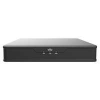

- Network Video Recorders
- Contents
- About this Manual....1
- Local Operations....2
- Initial Configuration....4
- Live View.... 11
- Channel Configuration....20
- Search....53
- VCA....71
- Network Configuration....114
- System Configuration....133
- Storage....150
- Alarm Configuration....165
- System Maintenance....181
- Playback....198
- Shutdown....207
- Web-Based Operations....208
- Appendix FAQ....211
- Copyright Statement
- Disclaimer
- Safety Symbols
- Local Operations
- Before You Begin
- Local Operations
- Mouse Operations
- Front Panel Buttons
- Initial Configuration
- Preparation
- Login
- Device Login
- Note:
- Reset Password
- Wizard
- Live View
- Live View Status
- Window Toolbar
- Digital Zoom
- Screen Toolbar
- Sequence
- Face Recognition
- Vehicle Recognition
- Multi-Sensor Preview
- Shortcut Menu
- Shortcut Menu
- Manual Operations
- Channel Configuration
- Channel Management
- IPC Configuration
- Add IPC
- Edit IP Camera
- Option 2
- Camera Offline
- Delete IP Camera
- Network Configuration
- IPC Password
- More Info
- Change Window Position
- Sort Camera
- Click, select Sort Camera.
- Batch Change Password
- Other Operations
- Fisheye Configuration
- Configuration
- Dewarping
- Advanced Functions
- Change Camera Password
- Camera Type
- Change Camera Type
- Add Analog Camera
- Audio & Video
- Encoding Settings
- Audio Configuration
- Display Configuration
- OSD Configuration
- OSD Content
- Image Settings
- Image Enhancement
- Exposure
- Smart Illumination
- White Balance
- Advanced Settings
- Privacy Mask
- Click Apply.
- PTZ Configuration
- PTZ Control Mode
- Configure PTZ
- OSD Menu
- Preset
- Preset Patrol
- Recorded Patrol
- Auto Guard
- Panoramic Linkage
- Enable Panoramic Linkage
- Enable Panoramic Linkage.
- Radar Configuration
- Add Radar
- Modify Radar
- Delete Radar
- Refresh
- Search
- Recording Backup
- Normal Video Backup
- Video Clip Backup
- Image Backup
- Normal Snapshot Backup
- Playback Snapshot Backup
- Event
- Smart Event
- Basic Event
- Object
- Person Search
- Human Body Search
- Face Snapshot Search
- Face Comparison Search
- Motor Vehicle Search
- Parameter Description
- Non-Motor Vehicle Search
- Statistics
- People Counting Report
- Heat Map
- VCA
- VCA Configuration
- Face Recognition
- Face Comparison
- Configure Monitoring Task
- View Library Sync Status
- View Real-time Snapshots
- Perimeter Protection
- Cross Line Detection
- Configure Cross Line Detection
- Intrusion Detection
- Configure Intrusion Detection
- Enter Area Detection
- Configure Enter Area Detection
- Leave Area Detection
- Configure Leave Area Detection
- Object Detection
- Traffic Monitoring
- Exception Detection & Statistics
- Defocus Detection
- Scene Change Detection
- Object Removed Detection
- Object Left Behind Detection
- Auto Tracking
- Temperature Detection
- Fire Detection
- Smoking Detection
- Temperature Measurement
- People Counting
- People Flow Counting
- Configure People Flow Counting
- View Real-time Statistics
- Crowd Density Monitoring
- Plate Detection
- Plate Detection
- Plate Comparison
- Alarm-triggered Actions
- Buzzer
- Pop-up Window
- Push Alarm
- Recording
- Goto Preset
- Preview
- Alarm Output
- Alarm Sound
- Flashing Light
- Snapshot
- Send Email
- Camera Linkage
- Arming Schedule
- Analyzer Configuration
- Library Management
- Face List
- Configure Face List
- Work Clothes Library
- Plate List
- Configure Plate List
- Smart Preview
- Face Recognition
- Perimeter Protection
- Vehicle Monitoring
- Object Detection
- Mixed-Traffic Detection
- People Flow Counting
- Network Configuration
- Basic Configuration
- Network Configuration
- EZCloud
- Configure EZCloud
- Add Device
- DDNS
- Click Apply.
- Platform Configuration
- SNMP
- Alarm Service
- Configure VIID Local
- Configure VIID Server
- Advanced Configuration
- PPPoE
- Port
- Port Mapping
- UPnP
- Manual
- Multicast
- FTP
- Wireless Local Area Network
- Wi-Fi AP
- Wi-Fi AP
- One-click pair (if you have a network cable)
- Scan code using the camera:
- Use the EZView app (if you don't have a network cable)
- Pair manually (if you have a network cable)
- System Configuration
- General Configuration
- Basic Configuration
- Time Configuration
- Basic Time Config
- System Time
- DST
- Camera Time Synchronization
- Sync Camera Time
- Holiday Configuration
- Preview Configuration
- Preview Configuration
- Screen Configuration
- Advanced Configuration
- POS Configuration
- POS OSD Configuration
- POS Configuration
- User Configuration
- Add User
- Delete User
- Edit User
- Security Configuration
- IP Address Filtering
- ONVIF Authentication
- Enable Authentication
- 802.1x
- ARP Protection
- Watermark
- Secure Password
- Advanced
- Serial Port
- Hot Spare
- Normal Mode
- Hot Spare Mode
- Unit
- Storage
- Recording Schedule
- Draw a Schedule
- Edit a Schedule
- Click Edit.
- Select a day.
- Snapshot Schedule
- Configure Snapshot Schedule
- Snapshot Type
- Array
- Automatically Create an Array
- Manually Create an Array
- Rebuild an Array
- Delete an Array
- Disk Management
- Configure the Disk Usage and Property
- Click OK.
- Add an External Disk
- Click Add.
- Format a Disk
- Disk Group
- Space Allocation
- Advanced Settings
- Alarm Configuration
- Motion Detection
- Motion Alarm
- Ultra Motion Detection
- Tampering Detection
- Human Body Detection
- Video Loss
- Alarm Input and Output
- Alarm Input
- Alarm Output
- Thermal Imaging
- Temperature Alarm
- Alert
- Audio Detection
- Buzzer
- People Present Alarm
- Configure People Present Alarm
- Configure parameters.
- Click Apply.
- View Data
- One-Key Disarming
- Manual Alarm
- Manual Alarm
- System Maintenance
- System Info
- Basic Info
- Camera Status
- Recording Status
- Online User
- HDD Status
- Decoding Card Status
- Network Information
- Network Traffic
- Packet Capture
- Network Check
- Configure Network Check
- View Test Results
- Export Test Results
- Network Status
- Network Resource Statistics
- PoE and Network Port Status
- Log Search
- Log Search
- Playback
- Log Backup
- Maintenance
- Maintenance
- Restore System
- System Backup
- Auto-Function
- Diagnosis Info
- NVR Diagnosis Info
- Camera Diagnosis Info
- One-Click Collection
- System Upgrade
- NVR Upgrade
- Choose Cloud Upgrade or Local Upgrade.
- - Cloud Upgrade
- - Local Upgrade
- IPC Upgrade
- Go to Menu > Maintenance > System Upgrade > IPC Upgrade.
- HDD Check
- Run S.M.A.R.T. Test
- Bad Sector Detection
- Playback
- Instant Playback
- Normal Playback
- Smart Playback
- Corridor Playback
- External File Playback
- Tag Playback
- Add Tag
- Tag Management
- Playback by Tag
- Playback by Search
- File Management
- Video Clip
- Playback Snapshot
- Locked File
- Tag
- Shutdown
- Preparation
- Login
- Live View
- Playback
- Configuration
- Smart
- Appendix FAQ
Brand : UniView
Model : NVR301-08-P8
Category : VCR