
BC ACS Split - Heat pump Baxi - Free user manual and instructions
Find the device manual for free BC ACS Split Baxi in PDF.


| Product Type | Split heat pump water heater |
| Series | BC ACS |
| Brand | Baxi |
| Application | Domestic hot water production and space heating |
| Refrigerant | R32 |
| Power Supply | 230 V / 50 Hz single phase |
| Outdoor Unit Dimensions (LxWxH) | 900 x 360 x 650 mm |
| Outdoor Unit Weight | 65 kg |
| Indoor Unit Dimensions (HxWxD) | 1800 x 600 x 600 mm |
| Indoor Unit Weight (empty) | 45 kg |
| Hot Water Tank Capacity | 200 L |
| COP (Coefficient of Performance) | Up to 5.0 |
| Energy Efficiency Class | A+++ |
| Sound Power Level (Outdoor) | 55 dB(A) |
| Operating Temperature Range | -20 °C to 43 °C |
| Max Hot Water Temperature | 65 °C |
| Main Functions | Heating, cooling, domestic hot water, anti-legionella cycle |
| Control Interface | Wired or wireless remote controller opt. |
| Maintenance | Clean air filters every 3 months; check pressure annually |
| Safety Features | Overheat, frost protection, safety valve, high pressure switch |
| Reparability | Repairable by qualified technician; spare parts available |
Frequently Asked Questions - BC ACS Split Baxi
User questions about BC ACS Split Baxi
0 question about this device. Answer the ones you know or ask your own.
Ask a new question about this device
Download the instructions for your Heat pump in PDF format for free! Find your manual BC ACS Split - Baxi and take your electronic device back in hand. On this page are published all the documents necessary for the use of your device. BC ACS Split by Baxi.
USER MANUAL BC ACS Split Baxi
Installation and Service Manual
Thermodynamic water heater
BC ACS Split
BC ACS 150 SPLIT
Serv. ref. SODU 2 M R1
Contents
1 Safety 4
1.1 General safety instructions 4
1.2 Recommendations 7
1.3 Specific safety instructions 8
1.4 R134a refrigerant 8
1.5 Liabilities 10
1.5.1 Manufacturer's liability 10
1.5.2 Installer's liability 10
2 Symbols used 12
2.1 Symbols used in the manual 12
2.2 Symbols used on the appliance 12
3 Technical specifications 13
3.1 Homologations 13
3.1.1 NF certification 13
3.1.2 EC Declaration of Conformity 13
3.1.3 Electrical Conformity / CE Marking 13
3.1.4 2014/68/UE Directive 13
3.1.5 Ecodesign Directive 13
3.2 Technical data 13
3.2.1 Technical data 13
3.2.2 Sensor specifications 14
3.3 Dimensions and connections 15
3.3.1 Domestic hot water tank dimensions 15
3.3.2 Outdoor unit dimensions 15
3.3.3 Control panel dimensions 15
3.4 Electrical diagram of the outdoor unit 16
4 Description of the product 18
4.1 General description 18
4.2 Limit temperatures of the thermodynamic water heater 18
4.3 Standard delivery 18
5 Before installation....19
5.1 Position of the data plates....19
5.2 Choice of the location 19
5.2.1 Selecting the location of the domestic hot water tank 19
5.2.2 Respect the distance between the domestic hot water tank and the outdoor unit .....21
5.2.3 Selecting the location of the outdoor unit .....21
5.2.4 Selecting the location of the control panel 23
6 Connecting diagrams 24
6.1 Connecting diagrams with external unit 24
6.1.1 Connection diagram .....24
6.1.2 Connecting diagram with boiler back-up (Hybrid mode) 24
6.2 Connecting diagrams without external unit 26
6.2.1 Connecting diagram....26
6.2.2 Connecting diagram with boiler back-up (Hybrid mode) 26
6.3 Description of the safety unit 27
6.4 Electrical connection diagrams with external unit 27
6.4.1 Electrical connection without off-peak/peak rate cables 27
6.4.2 Electrical connection with off-peak/peak rate cables 28
6.4.3 Electrical connection with off-peak/peak rate switch 28
6.5 Electrical connection diagrams without external unit 29
6.5.1 Electrical connection without off-peak/peak rate cables 29
6.5.2 Electrical connection with off-peak/peak rate switch 29
7 Installation....30
7.1 Recommendations 30
7.2 Install the appliances 30
7.2.1 Installing the domestic hot water tank to the wall without a tripod 30
7.2.2 Install the domestic hot water tank to the wall with a tripod 32
7.2.3 Installing the outdoor unit 34
7.2.4 Installing the control panel support 35
7.3 Hydraulic connections 36
7.3.1 Preparing the water connections 36
7.3.2 Connecting the domestic hot water tank to the cold water circuit 36
7.3.3 Connecting the domestic hot water circuit 37
7.4 Connecting the refrigeration connections 37
7.5 Electrical connections 38
7.5.1 Electrical recommendations....38
7.5.2 Electrically connecting the outdoor unit 39
7.5.3 Connecting the electrical connections of the domestic hot water tank with outdoor unit . . . . . . . . . . . . . . . . . . . . . . . . . . . . . . . . . . . . . . . . 40
7.5.4 Connecting the electrical connections of the domestic hot water tank with no outdoor unit . . . . . . . . . . . 41
7.5.5 Connecting the control panel display 41
7.6 Fill the domestic hot water tank....42
8 Commissioning 43
8.1 Checklist before commissioning 43
8.2 Initial commissioning 43
8.3 Checklist after commissioning 44
9 Setting the parameters 45
9.1 Activate / Deactivate the Holiday mode 45
9.2 Selecting the operating mode 45
9.3 Set the temperature threshold for the electrical back-up function .....46
9.4 Setting the hysteresis for starting water heating 46
10 Maintenance 47
10.1 General 47
10.2 Maintenance operation intervals 47
10.3 Operate the safety valve or unit 47
10.4 Maintenance of the outdoor unit 48
10.4.1 Checking the cooling circuit 48
10.4.2 Clean the fan and evaporator 48
10.4.3 Recover the refrigerant fluid in the outdoor unit 48
10.5 Maintenance of the domestic hot water tank 48
10.5.1 Draining the domestic hot water tank 48
10.5.2 Removing the inspection hatch 49
10.5.3 Descaling the domestic hot water tank 49
10.5.4 Checking the magnesium anode 50
10.5.5 Replacing the inspection hatch 50
10.6 Checks after a disconnection of the mains supply 51
10.7 Ordering spare parts 51
11 Troubleshooting....52
11.1 Resetting the safety thermostat 52
11.2 Resolving error codes 52
11.3 List of error codes 52
11.4 Clearing the error codes 54
11.5 Diagnosing errors on the outdoor unit 54
11.6 List of error codes for the outdoor unit 54
12 Disposal and recycling 56
12.1 Switching the thermodynamic water heater off 56
12.2 Disposing and recycling 56
13 Spare parts 57
13.1 Domestic hot water tank 57
13.2 Outdoor unit 59
14 Appendix....61
14.1 Maintenance form for the installer....61
1 Safety
1.1 General safety instructions

Danger
This appliance can be used by children aged 8 years and above and by persons with reduced physical, sensory or mental capabilities or lack of experience and knowledge when they have been given supervision or instruction concerning the safe use of the device and understand the resulting risks. Children must not be allowed to play with the appliance. Cleaning and user maintenance must not be carried out by children without supervision.

Danger
In the event of a refrigerant leakage:
- Switch off the appliance.
- Open the windows.
- Do not use a naked flame, do not smoke, do not operate electrical contacts.
- Avoid contact with the refrigerant. Danger of frost injuries.
- Locate the probable leak and seal it immediately.

Danger of electric shock
Before any work, switch off the mains supply to the thermodynamic water heater.

Important
Only qualified professionals are permitted to install the thermodynamic water heater, in accordance with prevailing local and national regulations.

Warning
Do not touch the refrigeration connection pipes with your bare hands while the heat pump is running. Danger of burn or frost injury.

Caution
Draining the domestic hot water tank:
- Shut off the domestic cold water inlet.
- Open a hot water tap in the installation.
- Open a valve on the safety unit.
- When the water stops flowing, the domestic hot water tank has been drained.

Caution
- The pressure limiter device (safety valve or safety unit) must be regularly operated in order to remove limescale deposits and ensure that it is not blocked.
- A pressure limiter device must be fitted to a discharge pipe.
- As water may flow out of the discharge pipe on the pressure limiter device, the pipe must be kept open to the air, in a frost-free environment, and at a continuous downward gradient.
- A pressure reducer (not provided) is required when the supply pressure exceeds 80% of the pressure limiter device calibration and must be located upstream of the appliance.
- There must be no cut-off devices between the pressure limiter device and the domestic hot water tank.
To ascertain the type, specifications and connection of the pressure limiter device, refer to the chapter Connecting the Domestic Hot Water Tank to the Drinking Water Mains in the Installation and Service Manual.

Warning
Install the appliance in accordance with national rules on electrical installation.
If the appliance is not wired in the factory, carry out the wiring according to the wiring diagram described in the chapter Electrical Connections in the appliance's instructions manual.
This appliance must be connected to the protective earth.

Warning
Earthing must comply with the prevailing installation standards.
Earth the appliance before making any electrical connections.
Type and calibre of the protective equipment: refer to the chapter Recommended cable cross-sections. See the Installation and Service Manual.
To connect the appliance to the mains supply, refer to the chapter Electrical Connections in the appliance's installation and service manual.

Warning
Respect the minimum and maximum water pressure and temperature to ensure the appliance operates correctly. See chapter on Technical Specifications.

Warning
Allow the space required to install the appliance correctly, referring to the chapter Dimensions of the Appliance. See the Installation and Service Manual.

Warning
A disconnection device must be fitted to the permanent pipes in accordance with installation rules.

Warning
If a power supply cable comes with the appliance and it turns out to be damaged, it must be replaced by the manufacturer, its after sales service or persons with similar qualifications in order to obviate any danger.

Caution
In order to prevent any danger owing to the unexpected reset of the thermal circuit breaker, this appliance must not be powered through an external switch, such as a timer, or be connected to a circuit which is regularly switched on and off by the electricity provider.

Warning
Respect the maximum water inlet pressure to ensure correct operation of the appliance, referring to the chapter Technical Specifications.

Warning
In order to limit the risk of being scalded, the installation of a thermostatic mixing valve on the domestic hot water flow pipes is obligatory.

Warning
Only qualified professionals are authorised to work on the heat pump and the heating system.

Caution
The system must satisfy each point in the rules in force in the country that govern works and interventions in individual homes, blocks of flats or other buildings.

Important
The user guide can also be found on our website.
1.2 Recommendations

Caution
To benefit from extended warranty cover, no modifications must be made to the appliance.

Important
Keep this document close to the place where the appliance is installed.

Important
Never remove or cover labels and data plates affixed to the appliances. Labels and data plates must be legible throughout the entire lifetime of the appliance.
Damaged or illegible instructions and warning stickers must be replaced immediately.

Important
Keep the thermodynamic water heater accessible at all times.
1.3 Specific safety instructions

Warning
Refrigerant fluid and pipes:
- Use only R134a refrigerant fluid to fill the installation.
- Use tools and pipe components especially designed for use with R134a refrigerant fluid.
- Use copper pipes deoxidised with phosphorus to carry the refrigerant fluid.
- Use beading to guarantee the tightness of the connections.
- Store the refrigerant connection pipes away from dust and humidity (risk of damage to the compressor).
- Cover both ends of the pipes until the beading process.
- Do not use a load cylinder.
1.4 R134a refrigerant
Tab.1 Effects harmful to health
| The vapours are heavier than air and may lead to asphyxia owing to reduced oxygen levels. | |
| Liquefied gas Contact with | the liquid may cause serious frost and eye injuries. |
| Product classification | This product is not classified as a "hazardous preparation" according to European Union regulations. |
Tab.2 Hazard identification
| If the R134a refrigerant is mixed with air, it may cause pressure surges in the refrigeration pipes and lead to an explosion and other hazards. |
Tab.3 Composition of/Information on the R134a
| Name | Proportion Number | CE Number | CAS | GWP^(1) |
| 1,1,1,2 - Tetrafluoroethane R134a 100 | % 212-377-0 | 811-97-2 1430 | ||
| (1) Global Warming Potential | ||||
Tab.4 First aid
| If inhaled Evacuate the subject from | the contaminated area and take him into the open air• If feeling unwell: call a doctor. |
| In the event of contact with the skin | • Treat frost injuries like burns. Rinse with copious amounts of tepid water, do not remove clothing (risk of adhesion to the skin)• If skin burns appear, call a doctor immediately |
| In the event of contact with the eyes | • Rinse immediately with water, holding the eyelids well apart (for at least 15 minutes)• Consult an ophthalmologist immediately |
Tab.5 Fire prevention measures
| Appropriate extinguishing agents All extinguishing agents can be used | |
| Inappropriate extinguishing agents None to our knowledge. In the event of fire nearby, use the appropriate extinguishing agents | |
| Specific hazards Rise in pressure: in the presence of air, an inflammable mixture may form under certain temperature and pressure conditionsToxic and corrosive vapours may be released by the effect of the heat | |
| Special intervention methods | Cool the volumes exposed to heat with water spray |
| Protection of the firemen Full self-contained breathing apparatus.Complete body protection | |
Tab.6 In the event of accidental spillage
| Individual precautions Avoid contact with the skin and eyes.Do not intervene without appropriate protective equipment.Do not inhale the vapourEvacuate the hazardous area.Stop the leakage.Eradicate all sources of ignition.Ventilate the spillage area mechanically (risk of asphyxia) | |
| Cleaning / Decontamination | Allow residual product to evaporate |
Tab.7 Personal protective equipment
| Respiratory protection | • If ventilation is insufficient: AX-type cartridge mask• In confined spaces: self-contained breathing apparatus |
| Hand protection Protective gloves in leather or nitrile rubber | |
| Eye protection Safety glasses with side protection | |
| Skin protection Clothing made primarily of cotton | |
| Industrial hygiene Do not drink, eat or smoke at the place of work | |
Tab.8 Handling
| Technical measures Ventilation | |
| Precautions to be tak-en | No smoking.Prevent the build-up of electrostatic charges.Work in a well ventilated place |
Tab.9 Considerations on disposal
| Disposal must be done in compliance with prevailing local and national regulations. | |
| Product waste Consult | It the manufacturer or the supplier for information on recovery or recycling |
| Soiled packaging Reuse | se or recycle after decontamination. Destroy in authorised installations |
Tab.10 Regulation
| • Regulation (EU) No. 517/2014 of the European Parliament and of the Council of 16 April 2014 on fluorinated greenhouse gases and repealing Regulation (EC) No. 842/2006. |
1.5 Liabilities
1.5.1 Manufacturer's liability
Our products are manufactured in compliance with the requirements of the various Directives applicable. They are therefore delivered with the C marking and any documents necessary. In the interests of the quality of our products, we strive constantly to improve them. We therefore reserve the right to modify the specifications given in this document.
Our liability as manufacturer may not be invoked in the following cases:
- Failure to abide by the instructions on installing and maintaining the appliance.
- Failure to abide by the instructions on using the appliance.
- Faulty or insufficient maintenance of the appliance.
1.5.2 Installer's liability
The installer is responsible for the installation and initial commissioning of the appliance. The installer must observe the following instructions:
- Read and follow the instructions given in the manuals provided with the appliance.
• Install the appliance in compliance with prevailing legislation and standards.
- Carry out initial commissioning and any checks necessary.
- Explain the installation to the user.
- If maintenance is necessary, warn the user of the obligation to check the appliance and keep it in good working order.
- Give all the instruction manuals to the user.
2 Symbols used
2.1 Symbols used in the manual
This manual uses various danger levels to draw attention to special instructions. We do this to improve user safety, to prevent problems and to guarantee correct operation of the appliance.

Danger
Risk of dangerous situations that may result in serious personal injury.

Danger of electric shock
Risk of electric shock.

Warning
Risk of dangerous situations that may result in minor personal injury.

Caution
Risk of material damage.

Important
Please note: important information.

See
Reference to other manuals or pages in this manual.
2.2 Symbols used on the appliance
Fig.1
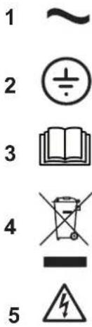

MW-2000407-2
1 Alternating current
2 Protective earthing
3 Before installing and commissioning the appliance, carefully read the instruction manuals provided.
4 Dispose of used products through an appropriate recovery and recycling structure.
5 Caution: danger of electric shock, live parts. Disconnect the mains power prior to carrying out any work.
6 Electrical back-up
7 CE Marking: equipment conforming to European legislation
8 NF Marking: equipment that respects French safety and performance criteria
9 Protection rating.
3 Technical specifications
3.1 Homologations
3.1.1 NF certification
- Specifications LCIE 103–15/B (July 2011) for NF Electricity Performance Marking
- This product complies with the requirements of the following NF Electricity Standards:
- EN 60335-1:2012 + A11:2014
- EN 60335-2-21:2003 + A1:2005 + A2:2008
- EN 60335-2-40:2003 + A11:2004 + A12:2005 + A1:2006 + A2:2009 + A13:2012
- EN 62233:2008
- EN 16147:2011
- EN 55014-1:2006+A1:2009+A2:2011
- EN 55014-2:2015
- EN 61000-3-2:2014
- EN 61000-3-3:2013
3.1.2 EC Declaration of Conformity
The unit complies with the standard type described in the EC declaration of conformity. It has been manufactured and commissioned in accordance with European directives.
The original declaration of conformity is available from the manufacturer.
3.1.3 Electrical Conformity / CE Marking
This product complies with the requirements of the following European Directives and Standards:
• Low Voltage Directive 2014/35/EU
Generic standard: EN 60335-1
Relevant standards: EN 60335-2-21, EN 60335-2-40
• Electromagnetic Compatibility Directive 2014/30/EU
Generic standards: EN 61000-6-3, EN 61000-6-1
Relevant Standard: EN 55014
3.1.4 2014/68/UE Directive
This product conforms to the requirements of European Directive 2014/68/UE, article 4, paragraph 3, on pressure equipment.
3.1.5 Ecodesign Directive
This product conforms to the requirements of European Directive 2009/125/EC on the ecodesign of energy-related products.
3.2 Technical data
3.2.1 Technical data
Tab.11 Technical parameters for heat pump water heaters
| Specification Unit BC ACS 150 SPLIT | ||
| Daily electricity consumption ( Q_elec ) ^(1) | kWh 3.597 | |
| Declared load profile - L | ||
| Sound power level, indoors ( L_WA ) dB 15 | ||
| Sound power level, outdoors ( L_WA ) ^(2) | dB (A) 59 | |
| Storage volume (V) I 150.0 | ||
| Mixed water at 40 °C (3) (V40) | I 205 | |
| Operating pressure MPa (bar) 1.0 (10) | ||
| Maximum water temperature °C 75 | ||
| Circuit breaker type C | ||
| Circuit breaker calibre A 16 | ||
| Power supply voltage - Frequency V - Hz 230 - 50 | ||
| Appliance name - air - water | ||
| R-134a refrigerant | kg | 1.60 |
| R-134a refrigerant(4) | tCO2e 2.28 | |
| Weight of the outdoor unit | kg | 33.5 |
| Gross weight of the domestic hot water tank (empty) | kg | 78 |
| Net weight of the domestic hot water tank (empty) | kg | 63.5 |
| Maximum operating amperage | A 11 | |
| Compressor oil | POE | |
| Maximum air flow rate | m3/h | 1300 |
| Limit operating temperatures of the outdoor unit | °C -15 / 42 | |
| Settings range for the domestic hot water set point | °C 25 / 75 | |
| Heating time (10-55 °C) (1) | Hours: Minutes | 04:05 |
| Absorbed electrical power (outdoor unit) | W | 9 |
| COP in accordance with the EN16147 standard (1) | 3.36 | |
| Domestic hot water reference temperature | °C 53.6 | |
| Output (outdoor unit) | W | 1750 |
| Pes (Power) (1)(5) | W | 9 |
| Immersion heater output | W | 1600 |
| Length of the refrigeration connection (minimum / maximum) | m | 2 / 20 |
| Maximum difference in height on the refrigeration connection | m | 10 |
| Protection of the domestic hot water tank | IP | 24 |
| Protection of the outdoor unit | IP | 24 |
| (1) Value obtained with an air temperature of 7°C and a cold water temperature of 10°C, as per LCIE specification No. 103-15/B:2011 based on the NF EN 16147 standard with a 5 m long refrigeration connection with 0 m difference in height.(2) Value obtained at an average air temperature of 20 °C with heating from de 10 °C to 55 °C.(3) The equivalent volume of hot water at 40 °C.(4) Quantity of refrigerant calculated in tonnes of CO2 equivalent.(5) Electrical power consumed with no hot water use. | ||
3.2.2 Sensor specifications
Tab.12 Temperature sensors: exchanger – outside air – suction
| Temperature (°C) | -20 | 0 | 20 | 40 | 60 | 80 | 100 | 120 |
| Resistance (KOhm) | 115 | 35.2 | 12.6 | 5.18 | 2.36 | 1.17 | 0.63 | 0.36 |
Tab.13 Domestic hot water tank temperature sensor
| Temperature (°C) | -20 | 0 | 20 | 40 | 60 | 80 | 100 | 120 |
| Resistance (KOhm) | 526 | 167 | 61.9 | 26.1 | 12.2 | 6.20 | 3.39 | 1.97 |
Tab.14 Air discharge temperature sensor
| Temperature (°C) | -20 | 0 | 20 | 40 | 60 | 80 | 100 | 120 |
| Resistance (KOhm) | 564 | 180 | 67.1 | 28.4 | 13.3 | 6.80 | 3.74 | 2.18 |
3.3 Dimensions and connections
3.3.1 Domestic hot water tank dimensions
Fig.2 BC ACS 150 SPLIT

1 Domestic hot water outlet
2 Domestic cold water inlet

3 1/4" refrigeration connection
4 3/8" refrigeration connection

MW-2000611-1
3.3.2 Outdoor unit dimensions
Fig.3
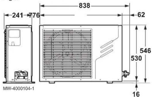
Dimensions in mm
3.3.3 Control panel dimensions
Fig.4
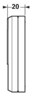

MW-4000105-3
Dimensions in mm
3.4 Electrical diagram of the outdoor unit
Fig.5

flowchart
graph TD
    A["Off Peak"] --> B["LCD"]
    A --> C["Off Peak"]
    C --> D["CCN1"]
    C --> E["CCN2"]
    C --> F["CCN3"]
    D --> G["Red"]
    E --> H["Yellow/Green"]
    F --> I["Blue"]
    G --> J["L O N H L O H N"]
    H --> K["Power supply"]
    I --> L["E-heater"]
    M["CCN4"] --> N["Black"]
    M --> O["P"]
    M --> P["Brown"]
    M --> Q["A"]
    M --> R["B"]
    M --> S["White"]
    T["CCN5"] --> U["Red"]
    V["CCN6"] --> W["Yellow/Green"]
    X["CCN7"] --> Y["Blue"]
    Z["CCN8"] --> AA["Red"]
    AB["CCN9"] --> AC["Blue"]
    AD["CCN10"] --> AE["Red"]
    AF["CCN11"] --> AG["Blue"]
    AH["CCN12"] --> AI["Red"]
    AJ["CCN13"] --> AK["TR"]
    AL["CCN14"] --> AM["Blue"]
    AN["CCN15"] --> AO["Red"]
    AP["CCN16"] --> AQ["Blue"]
    AR["CCN17"] --> AS["Red"]
    AT["CCN18"] --> AU["Blue"]
    AV["CCN19"] --> AW["Red"]
    AX["CCN20"] --> AY["Black"]
    AX --> AZ["Black"]
    BA["CCN21"] --> BB["Black"]
    BC["CCN22"] --> BD["Black"]
    BE["CCN23"] --> BF["Black"]
    BG["CCN24"] --> BH["Black"]
    BI["CCN25"] --> BJ["Black"]
    BK["CCN26"] --> BL["Black"]
    BM["CCN27"] --> BN["Black"]
    BO["CCN28"] --> BP["Black"]
    BQ["CCN29"] --> BR["Black"]
    BS["CCN30"] --> BT["Black"]
    BU["CCN31"] --> BV["Black"]
    BW["CCN32"] --> BX["Black"]
    BY["CCN33"] --> BZ["Black"]
    CA["CCN34"] --> CB["Black"]
    CC["CCN35"] --> CD["Black"]
    CE["CCN36"] --> CF["Black"]
    CG["CCN37"] --> CH["Black"]
    CI["CCN38"] --> CJ["Black"]
    CK["CCN39"] --> CL["Black"]
    CM["CCN40"] --> CNL["CN5"]
    CX["CCN41"] --> CY["CN6"]
    CZ["CN42"] --> DA["CN7"]
    DB["CN43"] --> DC["CN8"]
    DBC["CN8"] --> DY["CN9"]
    DY["CN9"] --> DYC["CN10"]
    DY["CN10"] --> DYV["CN11"]
    DY["CN11"] --> DYW["CN12"]
    DY["CN12"] --> DYX["CN13"]
    DY["CN13"] --> DYY["CN14"]
    DY["CN14"] --> DYZ["CN15"]
    DY["CN15"] --> DYX["CN16"]
    DY["CN16"] --> DYY["CN17"]
    DY["CN17"] --> DYZ["CN18"]
    DY["CN18"] --> DYX["CN19"]
    DY["CN19"] --> DYY["CN20"]

    subgraph PCB
        PCB_1["PCB"]
        PCB_2["PCB"]
        PCB_3["PCB"]
        PCB_4["PCB"]
        PCB_5["PCB"]
        PCB_6["PCB"]
        PCB_7["PCB"]
        PCB_8["PCB"]
        PCB_9["PCB"]
        PCB_10["PCB"]
        PCB_11["PCB"]
        PCB_12["PCB"]
        PCB_13["PCB"]
        PCB_14["PCB"]
        PCB_15["PCB"]
        PCB_16["PCB"]
        PCB_17["PCB"]
        PCB_18["PCB"]
        PCB_19["PCB"]
        PCB_20["PCB"]
        PCB_21["PCB"]
        PCB_22["PCB"]
        PCB_23["PCB"]
        PCB_24["PCB"]
        PCB_25["PCB"]
        PCB_26["PCB"]
        PCB_27["PCB"]
        PCB_28["PCB"]
        PCB_29["PCB"]
        PCB_30["PCB"]
        PCB_31["PCB"]
        PCB_32["PCB"]
        PCB_33["PCB"]
        PCB_34["PCB"]
        PCB_35["PCB"]
        PCB_36["PCB"]
        PCB_37["PCB"]
        PCB_38["PCB"]
        PCB_39["PCB"]
        PCB_40["PCB"]
        PCB_41["PCB"]
        PCB_42["PCB"]
        PCB_43["PCB"]
        PCB_44["PCB"]
        PCB_45["PCB"]
        PCB_46["PCB"]
        PCB_47["PCB"]
        PCB_48["PCB"]
        PCB_49["PCB"]
        PCB_50["PCB"]
        PCB_51["PCB"]
        PCB_52["PCB"]
        PCB_53["PCB"]
        PCB_54["PCB"]
        PCB_55["PCB"]
        PCB_56["PCB"]
        PCB_57["PCB"]
        PCB_58["PCB"]
        PCB_59["PCB"]
        PCB_60["PCB"]
        PCB_61["PCB"]
        PCB_62["PCB"]
        PCB_63["PCB"]
        PCB_64["PCB"]
        PCB_65["PCB"]
        PCB_66["PCB"]
        PCB_67["PCB"]
        PCB_68["PCB"]
        PCB_69["PCB"]
        PCB_70["PCB"]
        PCB_71["PCB"]
        PCB_72["PCB"]
        PCB_73["PCB"]
        PCB_74["PCB"]
        PCB_75["PCB"]
        PCB_76["PCB"]
        PCB_77["PCB"]
        PCB_78["PCB"]
        PCB_79["PCB"]
        PCB_80["PCB"]
        PCB_81["PCB"]
        PCB_82["PCB"]
        PCB_83["PCB"]
        PCB_84["PCB"]
        PCB_85["PCB"]
        PCB_86["PCB"]
        PCB_87["PCB"]
        PCB_88["PCB"]
        PCB_89["PCB"]
        PCB_90["PCB"]
        PCB_91["PCB"]
        PCB_92["PCB"]
        PCB_93["PCB"]
        PCB_94["PCB"]
        PCB_95["PCB"]
        PCB_96["PCB"]
        PCB_97["PCB"]
        PCB_98["PCB"]
        PCB_99["PCB"]
        PCB_A fill:#f9f,stroke:#333
    end

    %% Compartment
    subgraph Legend
    direction TB
    direction LR
    end

    %% Components
    subgraph Legend
    direction TB
    direction LR
    direction LR
    end

    %% Compressor
    subgraph Legend
    direction TB
    direction LR
    direction LR
    end

    %% Compartment
    direction TB
    direction LR
</details>
MW-4000107-3
Tab.15 Key
<table><tr><td>Connector Description</td><td></td></tr><tr><td>PCB Control system PCB</td><td></td></tr><tr><td>LCD Control panel</td><td></td></tr><tr><td colspan="2">Power 1 Control panel power supply</td></tr><tr><td>TR Transformer</td><td></td></tr><tr><td colspan="2">TRANS OUT Transformer outlet</td></tr><tr><td>TRANS IN Transformer inlet</td><td></td></tr><tr><td colspan="2">EEV Electronic expansion valve</td></tr><tr><td>FAN Fan</td><td></td></tr><tr><td>CAP1 Fan capacitor</td><td></td></tr><tr><td>Compressor</td><td>Compressor</td></tr><tr><td colspan="2">Compressor capacitor Compressor capacitor</td></tr><tr><td colspan="2">Power supply Electrical power supply</td></tr><tr><td>E-Heater Electrical back-up</td><td></td></tr><tr><td>OFF-PEAK Off-peak rate signal</td><td></td></tr><tr><td>N Neutral</td><td></td></tr><tr><td>L Live</td><td></td></tr><tr><td> + </td><td>Earth</td></tr><tr><td>CT1 Current transformer</td><td></td></tr><tr><td colspan="2">CT2 Differential current transformer</td></tr><tr><td>4-WAY VALVE 4-way valve</td><td></td></tr><tr><td>COM1 Control panel bus</td><td></td></tr><tr><td>LOW SPEED Low fan speed</td><td></td></tr><tr><td>HIGH SPEED High fan speed</td><td></td></tr><tr><td colspan="2">RT5L Domestic hot water tank temperature sensor</td></tr><tr><td colspan="2">RT3 Exchanger temperature sensor</td></tr><tr><td colspan="2">RT4 Outside air temperature sensor</td></tr><tr><td colspan="2">RTh Air suction temperature sensor</td></tr><tr><td colspan="2">RTp Air discharge temperature sensor</td></tr><tr><td>A - B - E - P - Q</td><td>OFF-PEAK terminal block connectors</td></tr><tr><td colspan="2">PRO_P High-pressure pressure switch</td></tr><tr><td>Compressor outside overload protection</td><td>Compressor outside overload protection</td></tr><tr><td>S1 Selector</td><td></td></tr><tr><td>SW1</td><td>Switch</td></tr></table>
Tab.16 Switches
<table><tr><td>Switch</td><td>OFF</td><td>ON</td></tr><tr><td>S1 - 1</td><td>-</td><td>-</td></tr><tr><td>S1 - 2</td><td>Anti-legionella mode disabled</td><td>Anti-legionella mode enabled</td></tr><tr><td>S1 - 3</td><td>Temperature in anti-legionella mode 65^ </td><td>Temperature in anti-legionella mode 70^ </td></tr></table>
Tab.17 Colour code
<table><tr><td>Colour</td><td>Description</td><td>Colour</td><td>Description</td><td>Colour</td><td>Description</td><td>Colour</td><td>Description</td></tr><tr><td>Black</td><td>Black</td><td>Brown</td><td>Brown</td><td>Orange</td><td>Orange</td><td>White</td><td>White</td></tr><tr><td>Blue</td><td>Blue</td><td>Grey</td><td>Grey</td><td>Red</td><td>Red</td><td>Yellow/Green</td><td>Yellow/Green</td></tr></table>
<h1 id="4-description-of-the-product">4 Description of the product</h1>
<h1 id="41-general-description">4.1 General description</h1>
The thermodynamic water heaters in the BC ACS Split range have the following specifications:
• Accumulation domestic hot water tank,
- Heat pump extracting energy from the outside air,
• Control panel with timer programming,
• 1600 W shielded immersion heater,
• Glass-lined tank protected by magnesium anode,
• Very thick insulation (0% CFCs).
The magnesium anode can be replaced by an impressed current anode available as optional equipment (package AJ38).
<h1 id="42-limit-temperatures-of-the-thermodynamic-water-heater">4.2 Limit temperatures of the thermodynamic water heater</h1>

X Air temperature (°C)
Y Domestic hot water temperature (°C)
The graph opposite shows the maximum temperature at which the outdoor unit can heat up the water in the domestic hot water tank according to air temperature.
To preserve the components and maintain an optimal service life of the thermodynamic water heater, the outdoor unit works at temperatures of between -15^ and +42^ . Outside of this temperature range, the surplus heating of the domestic hot water is provided by the immersion heater.
<h1 id="43-standard-delivery">4.3 Standard delivery</h1>
The thermodynamic water heater is delivered in several packages:
<table><tr><td colspan="2">Contents of the domestic hot water tank package Contents of the outdoor unit package</td></tr><tr><td>The domestic hot water tank The outdoor unit</td><td></td></tr><tr><td>The documentation bag The accessories box</td><td></td></tr></table>
<table><tr><td>Documentation bag</td></tr><tr><td>Accessories</td></tr><tr><td>An installation and service manual</td></tr><tr><td>A user guide</td></tr></table>
<table><tr><td>Accessories box</td></tr><tr><td>A condensates recovery pipette</td></tr><tr><td>A condensates discharge pipe</td></tr><tr><td>A control panel with wall bracket and all mounting screws and plastic dowels</td></tr><tr><td>A domestic hot water tank temperature sensor with 20 metres of cable</td></tr><tr><td>A 20-metre control panel connection cable</td></tr></table>
<h1 id="5-before-installation">5 Before installation</h1>
<h1 id="51-position-of-the-data-plates">5.1 Position of the data plates</h1>
Fig.7

<details>
<summary>text_image</summary>
MW-2000383-2
</details>
The data plates must be accessible at all times, they are used to identify the product and give the following information:
- Appliance type,
- Serial number,
• Electrical power supply.
<h1 id="52-choice-of-the-location">5.2 Choice of the location</h1>
Fig.8

<details>
<summary>text_image</summary>
580
6
566
Ø548
6
560x580
MW-2000384-2
</details>
<h1 id="521-selecting-the-location-of-the-domestic-hot-water-tank">5.2.1 Selecting the location of the domestic hot water tank</h1>
To ensure good accessibility and facilitate maintenance of the domestic hot water tank, its selected position should comply with the minimum dimensions indicated by the manufacturer.
Fig.9

<details>
<summary>text_image</summary>
75 mini
1273
150l
1225
350 mini
MW-2000651-2
</details>
Fig.10

<details>
<summary>text_image</summary>
150 mini
150l
1745
MW-2000652-1
</details>
1. Choose the location of the domestic hot water tank keeping in mind the dimensions indicated opposite.
2. Choose a room that complies with the following specifications:
- A room connected to an external wall to facilitate the connection between the domestic hot water tank and the outdoor unit,
- A dry room that is sheltered from frost and maintained at a temperature no lower than 7 °C,
- Avoid rooms that are exposed to gas, vapour or dust.
3. Observe the IP24 protection rating of the domestic hot water tank, during installation.
<h1 id="522-respect-the-distance-between-the-domestic-hot-water-tank-and-the-outdoor-unit">5.2.2 Respect the distance between the domestic hot water tank and the outdoor unit</h1>

<details>
<summary>text_image</summary>
Fig.11
10 m max
A
2 m min
20 m max
1
R= 38 mm min
B
MW-2000386-2
</details>
A Domestic hot water tank
B Outdoor unit
1 Maximum number of elbows: 15
To ensure that the thermodynamic water heater functions correctly, respect the minimum and maximum connection lengths between the domestic hot water tank and the outdoor unit.
If the refrigerant connections are less than 2 m long, the following disruptions may occur
• Functional disruptions caused by a fluid overload,
- Noise pollution caused by the circulation of the refrigerant.
1. Adhere to the dimensions opposite:
2. Make one or two horizontal loops with the refrigerant connections to reduce disruption.

<details>
<summary>text_image</summary>
Fig.12
MW-M001448-2
</details>
<h1 id="523-selecting-the-location-of-the-outdoor-unit">5.2.3 Selecting the location of the outdoor unit</h1>
To ensure the outdoor unit operates correctly, its location must meet certain conditions.
1. Decide on the ideal location for the outdoor unit, bearing in mind the space it requires and any legal directives and in relation to neighbours as it is a source of noise.
2. Observe the IP24 protection rating of the outdoor unit during installation.
3. Avoid the following locations:
\- Prevailing winds. Nothing must obstruct the free circulation of air around the outdoor unit (intake and outlet).
\- Close to sleep zones,
\- Close to a terrace.
• Opposite a wall with windows,
4. Ensure the support meets the following specifications:
<table><tr><td>Specifications Examples</td><td></td></tr><tr><td>Flat surface that can support the weight of the outdoor unit and its accessories</td><td>Concrete base,Sill,Concrete blocks,No rigid connection to the building served to avoid the transmission of vibration</td></tr><tr><td>Sufficient above ground elevation (100 to 500 mm) to keep it above water</td><td>Base with a metal frame to allow condensates to be discharged correctly.The width of the base must not exceed the width of the outdoor unit.The condensates discharge must be regularly cleaned in order to prevent any block-ages</td></tr></table>
<h1 id="choosing-the-location-of-a-noise-abatement-screen">■ Choosing the location of a noise abatement screen</h1>
When the outdoor unit is too close to neighbours, a noise abatement screen can be fitted to reduce noise pollution.
Fig.13

<details>
<summary>text_image</summary>
Diagram illustrating a house with a warning sign and a person pointing to a building, showing safety warnings like 'Brm'.
</details>
MW-C000373-1
Fig.14

1. Locate the noise abatement screen as close as possible to the noise source whilst allowing for the free circulation of air in the exchanger on the outdoor unit and maintenance work.
2. Respect the following minimum positioning distances of the outdoor unit from the wall.
<table><tr><td colspan="2">BC ACS Split A B C D E</td><td></td><td></td><td></td><td></td></tr><tr><td>Minimum dimensions in mm</td><td>300 1500</td><td>500 200 600</td><td></td><td></td><td></td></tr></table>
■ Selecting the location of the outdoor unit in cold and snowy regions
Wind and snow can significantly reduce the performance of the outdoor unit, the location of the outdoor unit must meet the following conditions.
Fig.15

<details>
<summary>text_image</summary>
1 2 3/
4
</details>
MW-6000252-2
1. Install the outdoor unit sufficiently high off the ground to allow condensates to be discharged correctly.
2. Ensure the base meets the following specifications:
<table><tr><td>Specifications Reason</td><td></td></tr><tr><td>Maximum width equal to the width of the outdoor unit.</td><td></td></tr><tr><td>Height at least 200 mm greater then the average depth of the covering of snow.</td><td>This helps to protect the exchanger from snow and prevent the formation of ice during the defrosting operation.</td></tr><tr><td colspan="2">Location as far as possible from the thoroughfare. The condensates discharge may freeze, causing a potential hazard (sheet of black ice).</td></tr></table>
3. If the outside temperatures drop below zero, take the necessary precautions to prevent the risk of freezing in the evacuation pipes.
4. Place the outdoor units beside each other and not on top of each other to prevent the condensates from the lower unit to freeze.
<h1 id="524-selecting-the-location-of-the-control-panel">5.2.4 Selecting the location of the control panel</h1>
For ergonomic reasons, the control panel must be at eye level in a clean room.
1. Select a room in the building according to the following recommendations:
- Avoid areas of excessive moisture or oil vapour (such as a kitchen or bathroom),
- Keep away from powerful electrical appliances to avoid any interference.
2. Install the control panel against a wall at eye level in the chosen room.
Fig.16

<details>
<summary>text_image</summary>
88°C 88:88
MW-400012D-3
</details>
<h1 id="6-connecting-diagrams">6 Connecting diagrams</h1>
<h1 id="61-connecting-diagrams-with-external-unit">6.1 Connecting diagrams with external unit</h1>
<h1 id="611-connection-diagram">6.1.1 Connection diagram</h1>
Fig.17

<details>
<summary>text_image</summary>
A
1
2
7
8
9
3
4
5
6
C
D
B
10-12
11
</details>
MW-2000388-2
A Domestic hot water tank
B Outdoor unit
C Electrical box
D Control panel
1 Domestic hot water outlet
2 Domestic cold water inlet
3 Power supply cable for the immersion heater
4 Domestic hot water sensor
5 Refrigeration connection out
6 Refrigeration connection in
7 Valve with plug
8 Safety unit
9 Pressure reducer
10 General power supply cable
11 Off-peak/peak rate signal cable
12 Control panel communication cable
<h1 id="612-connecting-diagram-with-boiler-back-up-hybrid-mode">6.1.2 Connecting diagram with boiler back-up (Hybrid mode)</h1>
The Hybrid mode requires a water connection between the domestic hot water tank and an instant boiler.
Fig.18

<details>
<summary>text_image</summary>
E
230V
50Hz
A
1
2
7
8
9
3
4
5
6
C
D
10-11
B
MW-2000616-1
</details>
A Domestic hot water tank
B Outdoor unit
C Electrical box
D Control panel
E Instant boiler
1 Domestic hot water outlet
2 Domestic cold water inlet
3 Power supply cable for the immersion heater
4 Domestic hot water sensor
5 Refrigeration connection out
6 Refrigeration connection in
7 Valve with plug
8 Safety unit
9 Pressure reducer
10 General power supply cable
11 Control panel communication cable
<h1 id="62-connecting-diagrams-without-external-unit">6.2 Connecting diagrams without external unit</h1>
<h1 id="621-connecting-diagram">6.2.1 Connecting diagram</h1>

<details>
<summary>text_image</summary>
Fig.19
A
1
2
3
5
6
7
C
MW-2000647-2
</details>
A Domestic hot water tank
C Electrical box
1 Domestic hot water outlet with dielectric union
2 Domestic cold water inlet with dielectric union
3 Power supply cable for the immersion heater
5 Valve with plug
6 Safety unit
7 Pressure reducer
<h1 id="622-connecting-diagram-with-boiler-back-up-hybrid-mode">6.2.2 Connecting diagram with boiler back-up (Hybrid mode)</h1>
The Hybrid mode requires a water connection between the domestic hot water tank and an instant boiler.

<details>
<summary>text_image</summary>
Fig.20
E
A
C
1
2
3
7
6
5
MW-2000648-2
</details>
A Domestic hot water tank
C Electrical box
E Instant boiler
1 Domestic hot water outlet
2 Domestic cold water inlet
3 Power supply cable for the immersion heater
5 Safety unit
6 Pressure reducer
7 Valve with plug
<h1 id="63-description-of-the-safety-unit">6.3 Description of the safety unit</h1>
Fig.21

<details>
<summary>text_image</summary>
55
30
9
27
17
29
9
28
2 cm
(54)
L000370-C
</details>
9 Isolation valve
17 Drain valve
27 Non-return valve
28 Domestic cold water inlet
29 Pressure reducer
30 Safety unit
54 End of the discharge pipe free and visible 2 to 4 cm above the flow funnel
55 Domestic hot water diaphragm safety valve, sealed and calibrated to 7 bar
<h1 id="64-electrical-connection-diagrams-with-external-unit">6.4 Electrical connection diagrams with external unit</h1>
<h1 id="641-electrical-connection-without-off-peakpeak-rate-cables">6.4.1 Electrical connection without off-peak/peak rate cables</h1>
Fig.22

<details>
<summary>text_image</summary>
538kW/h
C1 C2
15/45 A
500 mA
4
5
7
30 mA
TEST
16 A+0 A
L
N
HL
HN
3
1
MW-2000381-2
</details>
1 Domestic hot water tank
2 Outdoor unit:
- HL: Phase of the immersion heater power supply
- HN: Neutral of the immersion heater power supply
3 Control panel
4 Electricity meter
5 Connection circuit breaker
6 AC-type differential circuit breaker
7 Circuit breaker
<h1 id="642-electrical-connection-with-off-peakpeak-rate-cables">6.4.2 Electrical connection with off-peak/peak rate cables</h1>
Fig.23

<details>
<summary>text_image</summary>
538 kW/h
C1 C2
15 / 45 A
500 mA
4
5
30
mA
TEST
16 A 40 A
7
6
L
N
HL
HN
3
1
MW-2000613-1
</details>
1 Domestic hot water tank
2 Outdoor unit
- HL: Phase of the immersion heater power supply
- HN: Neutral of the immersion heater power supply
3 Control panel
4 Electricity meter
5 Connection circuit breaker
6 AC-type differential switch
7 Circuit breakers
<h1 id="643-electrical-connection-with-off-peakpeak-rate-switch">6.4.3 Electrical connection with off-peak/peak rate switch</h1>
Fig.24

<details>
<summary>flowchart</summary>
```mermaid
graph TD
A["538 kW/h C1 C2"] --> B["15/45 A 500 mA"]
B --> C["30 mA TEST"]
B --> D["16 A 40 A 2 A"]
C --> E["A1"]
D --> F["A2"]
E --> G["L"]
F --> H["N"]
G --> I["HL"]
H --> J["HN"]
I --> K["1"]
J --> L["3"]
style A fill:#f9f,stroke:#333
style K fill:#ccf,stroke:#333
style L fill:#cfc,stroke:#333
1 Domestic hot water tank
2 Outdoor unit
- HL: Phase of the immersion heater power supply
- HN: Neutral of the immersion heater power supply
3 Control panel
4 Electricity meter
5 Connection circuit breaker
6 AC-type differential switch
7 Circuit breakers
8 Peak rate/off-peak rate switch
6.5 Electrical connection diagrams without external unit
6.5.1 Electrical connection without off-peak/peak rate cables
Fig.25
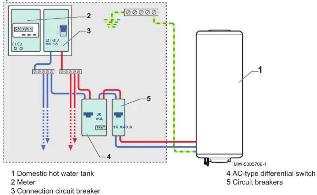
6.5.2 Electrical connection with off-peak/peak rate switch
Fig.26

1 Domestic hot water tank
2 Meter
3 Connection circuit breaker
4 AC-type differential switch
5 Circuit breakers
6 Peak rate/off-peak rate switch
7 Installation
7.1 Recommendations
The appliances must be installed by a certified professional in accordance with prevailing statutory texts and codes of practice.
The installation must comply on all points with prevailing regulations and directives, which govern work and interventions in individual homes, blocks of flats and other buildings.
When installing the appliances, respect the protection ratings: IP24 for the domestic hot water tank and IP24 for the outdoor unit.
When choosing the location of the domestic hot water tank, the outdoor unit and the control panel, the installer must adhere to the following recommendations:
- Install a water drain in the boiler room.
- Ensure there is a funnel-siphon for the safety unit.
- Install isolation valves.
- Fit a pressure reducer.
- Fit a non-return valve to the domestic cold water circuit.
7.2 Install the appliances
7.2.1 Installing the domestic hot water tank to the wall without a tripod
The domestic hot water tank wall mounting must take into consideration the robustness of the wall. If the wall is thin, you must use the Tripod option: Réf. 89788949.
The installer is responsible for the type of mounting used and the mechanical integrity of the assembly including the bracket selection.
The screws, dowels and washers necessary to mount the brackets to the wall are not provided.
The mounting brackets are supplied in the polystyrene base of the domestic hot water tank.
Fig.27
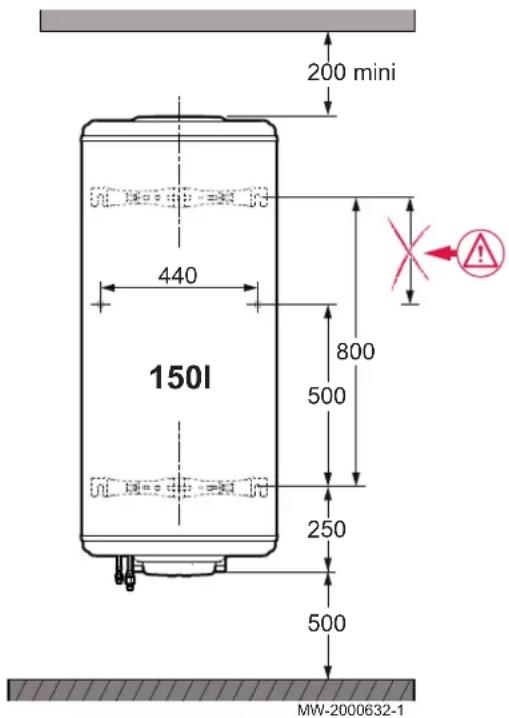
- Take note of the dimensions indicated in the diagram below to position the domestic hot water tank on the wall.
- Select the position of the upper and lower mounting brackets of the domestic hot water tank, within the constraints of the wall being mounted to (cable and pipe channels):
| 150L | |
| Position of the upper bracket | 2 position options |
| Position of the lower bracket | only 1 position permitted |
- Pre-fit to the wall with the screws protruding by at least 15 mm. The M10 screws to use will depend on the type of wall. The screws must be able to support the weight of the domestic hot water tank when it is full of water.
Fig.28

- Fix the brackets to the domestic hot water tank the correct way round, using the screws and washers on the domestic hot water tank, while supporting the appliance to avoid any tipping.
Fig.29
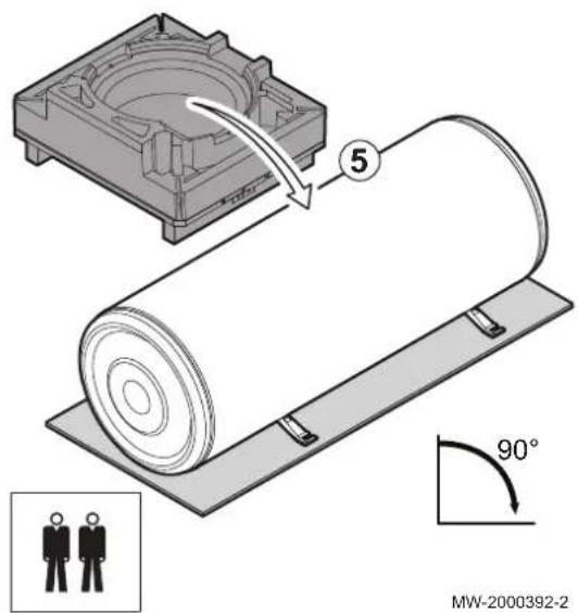
- Tilt the domestic hot water tank onto its brackets.
Fig.30

-
Attach the domestic hot water tank by inserting the brackets onto the screws.
-
Fasten the screws.
Fig.31

7.2.2 Install the domestic hot water tank to the wall with a tripod
The tripod option: Réf. 89788949, is mandatory when the wall to be fitted to is not strong enough to support the weight of a full domestic hot water tank.
The installer is responsible for the type of mounting used and the mechanical integrity of the assembly including the bracket selection.
The screws, dowels and washers necessary to mount the brackets to the wall are not provided.
The mounting brackets are supplied in the polystyrene base of the domestic hot water tank.
The Tripod option must be fitted to a flat and solid surface.
With a Tripod, the domestic hot water tank must be mounted to the wall with the upper bracket to prevent any tipping.
- Pre-position the Tripod taking into consideration the dimensions indicated in the diagram below to position the domestic hot water tank on the wall. The Tripod must be at 42 mm from the wall.
- Select the position of the upper mounting bracket of the domestic hot water tank, within the constraints of the wall being mounted to (cable and pipe channels):
| 150L | |
| Position of the upper bracket | 2 position options |
The position of the lower bracket is not important, however, the lower bracket must still be fixed to the domestic hot water tank for the operations that follow.
- Pre-fit to the wall with the screws protruding by at least 15 mm. The M10 screws to use will depend on the type of wall. The screws must be able to support the weight of the domestic hot water tank when it is full of water.
Fig.32

- Fix the brackets to the domestic hot water tank the correct way round, using the screws and washers on the domestic hot water tank, while supporting the appliance to avoid any tipping.
Fig.33

- Tilt the domestic hot water tank onto its brackets.
Fig.34
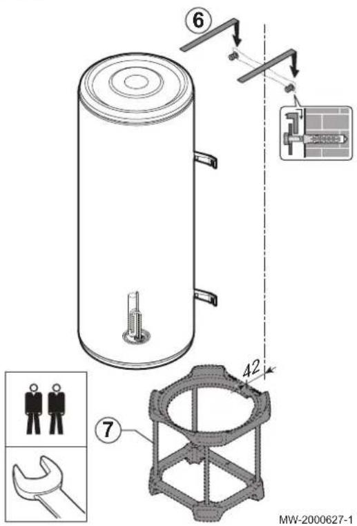
- Attach the domestic hot water tank by inserting the upper bracket onto the screws.
The domestic hot water tank must rest on the tripod.
- Fasten the screws.
7.2.3 Installing the outdoor unit
■ Installing the outdoor unit on the ground
When mounting to the ground, install a concrete base.
The data plate must be accessible at all times.
- Dig a run-off channel with a pebble bed.
- Install a concrete base frame with a minimum height of 80 mm capable of bearing the weight of the outdoor unit.
- Install the outdoor unit on the concrete base frame.
Fig.35

Fig.36

■ Installing the outdoor unit on its wall bracket
For wall mounting, fit the wall support kit and the anti-vibration studs available separately: package EH95.
The data plate must be accessible at all times.
- Mount the wall bracket with the horizontal plane at least 200 mm above the ground.
- Fit anti-vibration studs under the outdoor unit.
- Mount the outdoor unit on its wall bracket. The mounting screws are provided in the package EH95.
Fig.37
7.2.4 Installing the control panel support
The control panel is supplied with the outdoor unit.
The control panel must be positioned at eye level in a room free from moisture and oil vapour (such as a kitchen or bathroom). Keep away from powerful electrical appliances to avoid any interference.
Fit cable sleeves for the power supply to the control panel as well as the connection between the control panel and the outdoor unit.
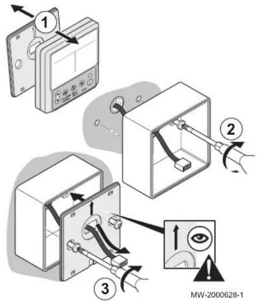
- Open the control panel by unclipping the cover on the wall bracket.
- Mount the support box, routing the cable through the hole provided for this purpose.
Do not over-tighten the screws, to prevent deforming the back panel and breaking the display.
The support box as well as the mounting screw are supplied in the accessories box of the outdoor unit. - Fit the wall support cover, routing the cable through the hole provided for this purpose.

For more information, see
Connecting the control panel display, page 41
7.3 Hydraulic connections
Fig.38

7.3.1 Preparing the water connections
1 Domestic hot water outlet (red collar) 2 Domestic cold water inlet (blue collar)
The components used for the connection to the cold water circuit must comply with the prevailing standards and regulations in the country concerned.
The water connections must comply with the corresponding standards and local directives.
- Remove the lower cover.
- The domestic hot water circuits and cold water feed pipes must be flushed before making any water connections to prevent metal particles or other contaminants into the domestic hot water tank. If flushing has to be done using an aggressive product, neutralise the rinsing water before disposing of it in the waste water network.
7.3.2 Connecting the domestic hot water tank to the cold water circuit
- Install a pressure reducer if the mains pressure exceeds 80% of the calibration of the safety valve or unit (e.g. 0.55 MPa (5.5 bar) for a safety unit calibrated to 0.7 MPa (7 bar)).

Caution
Install the pressure reducer upstream of the appliance and downstream of the water meter in such a way as to ensure the same pressure in all of the system's pipes.
- Install a non-return valve between the safety unit and the pressure reducer to prevent the backflow of domestic hot water into the domestic cold water circuit.
- Install a water drain in the boiler room and a funnel-siphon for the safety unit.
- Incorporate a sealed safety valve calibrated to 0.7 MPa (7 bar) (not provided) on the domestic cold water inlet, close to the tank, in a position which is easy to reach, to protect the domestic hot water tank from pressure surges.

Caution
There must be no cut-off devices between the safety valve or unit and the domestic hot water tank.
- To avoid restricting the flow of water in the event of overpressure:
- the safety unit discharge pipe must be kept in the open, in a frost-free environment, and have a continuous, downward gradient;
-
the diameter of the safety unit and its connection to the tank must be at least equal to the diameter of the domestic cold water inlet on the tank.
-
Make the connection to the domestic cold water.
7.3.3 Connecting the domestic hot water circuit
Fig.39

The dielectric unions are provided in the documentation bag.
- A dielectric union must be connected using hemp fibre or pipe joint compound, between the hot water outlet (red collar) of the domestic hot water tank and the pipework to avoid any corrosion at the union.
- A dielectric union must be connected using hemp fibre or pipe joint compound, between the cold water inlet (blue collar) of the domestic hot water tank and the pipework to avoid any corrosion at the union.
- Mount a domestic water thermostatic mixer valve (not provided) on the domestic hot water tank outlet:
• France: the thermostatic mixer valve is mandatory. - Other countries: the thermostatic mixer valve is recommended.
7.4 Connecting the refrigeration connections
To allow exchanges between the domestic hot water tank and the outdoor unit, 2 refrigerant connections must be made: send and return.
Pursuant to directive L. 517/2014, the installation of equipment must be done by a certified operator whenever the refrigerant load is in excess of two kilograms or when a refrigerant connection is necessary (the case with split systems, even when fitted with a quick coupling device).
Fig.40

| 3/8" fitting supplied on the outdoor unit supplied in the documentation bag | |
| 1/4" fitting supplied on the outdoor unit supplied on the domestic hot water tank |
-
Partially unscrew the 3/8" adaptor on the domestic hot water tank. ⇒ If no release noise can be heard, return the product to the after-sales service.
-
Connect the refrigerant connections to the domestic hot water tank and the outdoor unit by applying refrigerant oil to the beaded parts to facilitate tightening and improve the seal, while keeping to the following tightening torques:
| External diameter of the pipe (mm/inch) | External diameter of the cone fitting (mm) | Torque load (N.m) |
| 6.35 - 1/4 17 14 - 18 | ||
| 9.52 - 3/8 22 34 - 42 |
- Carry out a seal test of the refrigerant circuit, putting it under a pressure of up to 25 bar, in 5 bar increments.
- Place the refrigerant installation under vacuum using a vacuum gauge and a vacuum pump.
- Check the pressure according to the recommendations table below:
| Outside temperature in °C ≥ 20 10 0 - | 10 | |||
| Pressure to reach in Pa (bar) | 1000(0.01) | 600(0.006) | 250(0.0025) | 200(0.002) |
| Evacuation time after reaching the pressure in hour(s) | 1 1 2 3 | |||
- Open the valves with a hexagonal key by turning anti-clockwise until it stops.
- Fit the insulation on the refrigerant connections on the domestic hot water tank side.
The refrigerant connection insulation pieces are provided in the documentation bag.
7.5 Electrical connections
7.5.1 Electrical recommendations
Only qualified professionals may carry out electrical connections, always with the power off.
Separate the very low voltage cables from the 230V circuit cables.
The electrical power supply is done by means of a mains connection cable ( 230 V, 50 Hz) in accordance with prevailing national regulations for electrical installations.
Respect the polarities when making the electrical connections to the mains:
- Brown wire (L) : Live
- Blue wire (N) : Neutral
-
Green/yellow wire Earth
-
If the power supply cable is damaged, you must have it replaced by a qualified installer.
- Do not connect the power supply directly to the peak/off-peak rate contact.
7.5.2 Electrically connecting the outdoor unit

1 Control panel electrical cable
2 General electrical cable of the outdoor unit
3 Immersion heater electrical cable
4 Temperature sensor cable
5 Peak/off-peak rate cable
The 3G power supply cable of a maximum length of 20 m and a 2.5 mm ^4 section to connect the outdoor unit, is provided by the installer.
- Remove the service panel from the outdoor unit in order to access the electrical terminal block.
- Connect the general power supply cable to the appropriate terminals.
- Connect the immersion heater power supply cable to the appropriate terminals.
- Secure the mains power supply cables with the traction arrester.
- Connect the control panel power supply cable to the appropriate terminals.
- Connect the domestic hot water tank temperature sensor connector to the appropriate terminals.
- Connect the off-peak/peak rate connector to the appropriate terminals, in the case where the off-peak signal is to be used.
- Replace the service panel passing the cables through the passage provided for this purpose in the panel.
7.5.3 Connecting the electrical connections of the domestic hot water tank with outdoor unit
Fig.42


The 1.5 mm^2 section power supply cable for the electrical connection of the domestic hot water tank, is provided by the installer.
- Feed the electrical power supply cable through the lower cover of the domestic hot water tank. Leave enough cable length to allow removal.
- Connect the earth wire to the inspection hatch.
- Connect phase and neutral to the thermostat of the domestic hot water tank.
- Tighten the traction arrestor to hold tight the power supply cable.
- Disconnect the sensor from its lead.
- Insert the temperature sensor into the sensor tube until it stops, sliding out and pushing back past the traction arrestor.
- Pass the sensor cable through the lower cover.
- Tighten the traction arrestor.
- Secure the lower cover with screws.
7.5.4 Connecting the electrical connections of the domestic hot water tank with no outdoor unit
Fig.43

The 1.5 mm ^2 section power supply cable for the electrical connection of the domestic hot water tank is provided by the installer.
- Feed the electrical power supply cable through the lower cover of the domestic hot water tank.
- Connect the earth wire to the inspection hatch.
- Connect phase and neutral to the thermostat of the domestic hot water tank.
- Tighten the traction arrestor to hold tight the power supply cable.
- Secure the lower cover with screws.
Fig.44

7.5.5 Connecting the control panel display
During installation, leave enough cable length to allow removal of the control panel for maintenance.
- Connect the control panel display.
- Clip the display fascia onto the control panel support.
7.6 Fill the domestic hot water tank.
Fig.45

When the water and electrical connections are made, fill the domestic hot water tank.
- Turn on a hot water tap.
- Check that the outdoor unit drain valve is in the closed position.
- Open the cold water tap located on the safety unit to vent the air in the installation.
- Close the hot water tap when water starts to flow from the tap. ⇒ The domestic hot water tank is full.
- Check the tightness of the pipe connections and the correct operation of the hydraulic devices by successively opening the drain valve on the safety unit.
8 Commissioning
8.1 Checklist before commissioning
Tab.18 General checks
| Inspection points Checked? | |
| Position of the outdoor unit, distance from the wall | |
| Tightness of the refrigerant fittings | |
| Pressure during evacuation prior to filling | |
| Evacuation time and outside temperature during evacuation | |
| Domestic hot water tank filled with water |
Tab.19 Electrical checks
| Inspection points Checked? | |
| Electrically checking the magnesium anode Start value: | |
| Presence of the recommended circuit breaker | |
| Tightened terminal blocks | |
| Separation of the power and low voltage cables | |
| Mounting and positioning of the sensor |

For more information, see
Check the current of the magnesium anode, page 50
8.2 Initial commissioning
Fig.46

Initial commissioning must be performed by a qualified professional.
Commissioning of the thermodynamic water heater should be carried out:
- When it is used for the first time;
• After a prolonged shut-down;
• After any event that may require complete re-installation.
Commissioning of the thermodynamic water heater allows the user to review the various settings and checks to be made to start up the water heater in complete safety.
- Switch on the installation.
| Indicator light on Domestic hot water production active | |
| Indicator light off Domestic hot water production inactive.Frost protection function active.Outside of off-peak rate.The thermodynamic water heater is in Holiday Mode. |
- Switch on the control panel by pressing the key:
The compressor starts up after 3 minutes if domestic hot water production is required.
If an error code appears on the control panel, refer to the list of error codes.

For more information, see
Activate / Deactivate the Holiday mode, page 45
List of error codes, page 52
Clearing the error codes, page 54
8.3 Checklist after commissioning
Fig.47

A few days after the appliance is commissioned, check the installation.
- Check the tightness of the connections.
- Check the water pressure.
- Check that there are no errors on the control panel.
- Inform the user of the frequency of maintenance work to be carried out.
- Explain how the system and control panel work to the users.
- Hand over all manuals to the user.
9 Setting the parameters

For more information, see
Checks after a disconnection of the mains supply, page 51
9.1 Activate / Deactivate the Holiday mode
Fig.48

For extended periods away, switch the thermodynamic water heater to Holiday mode.
The Holiday mode should be used rather than shutting down the thermodynamic water heater to ensure the following functions operate:
- Frost protection,
-
Saving control panel parameters.
-
Press the key on the control panel.
→ The indicator light goes out: Holiday mode is activated. - Press the key on the control panel.
⇒ The indicator light comes on: Holiday mode is deactivated.
9.2 Selecting the operating mode
-
Access the list of available operating modes by simultaneously pressing the ▲ and keys.
-
Select the desired mode by pressing the ▲ key.
| Digit O | Operating mode | Description Adjustment required | |
| 0 | Automatic mode | Domestic hot water is heated according to the climate conditions:by the heat pump, and/orby the immersion heater. | / |
| 1 | Hybrid mode | Domestic hot water is:first pre-heated using the heat pump,then heated by the instant boiler. | THmin setting: heat pump minimum operating temperature. |
| 2 | Optimisation Mode | Domestic hot water is heated for pre-determined periods:by the timer programming,by the off-peak rate signal.Domestic hot water is heated by the heat pump and by the immersion heater to reach the set point temperature before the end of the off-peak rate. | H1 setting: duration (in hours) of the longest off-peak time range. |
| 3 | Consumption mode | Read the different consumption values | |
| 4 | Cooling mode | The refrigerant can be recovered. | |
| 5 | Immersion heater power |
- Confirm the selection by pressing the

9.3 Set the temperature threshold for the electrical back-up function
Fig.49

The electrical back-up function is authorised to operate when the outside temperature falls below a certain threshold. This threshold can be adjusted.
- Press the key for 3 seconds.
→ The Electrical Heating and Set Temp icons flash. - Set the temperature threshold with the ▲ keys.
- Confirm the temperature threshold by pressing the key.
9.4 Setting the hysteresis for starting water heating
In order to avoid the thermodynamic water heater from shutting down and starting up too frequently, it is possible to configure the hysteresis for activating water heating.
- Access the activation hysteresis settings by pressing the ▼ and keys simultaneously for 3 seconds.
- Set the hysteresis with the ▲ keys.
- Confirm the hysteresis by pressing the key.
For a desired domestic hot water temperature of 55^ C with hysteresis of 2^ C:
- When the domestic hot water temperature is above 57^ , the thermodynamic water heater is switched off.
- When the domestic hot water temperature is below 53^ , the thermodynamic water heater is switched on.
10 Maintenance
10.1 General
Fig.50


Caution
Do not neglect to service the domestic hot water tank or the heat pump. Contact a qualified professional or take out a maintenance contract for the obligatory annual servicing of the thermodynamic water heater.
Failure to service the appliance voids the warranty.
The control and maintenance interventions for the appliance must be performed by a certified professional in accordance with prevailing statutory texts and codes of practice.
Maintenance operations are important for the following reasons:
• To guarantee optimum performance;
• To extend the life of the equipment;
- To provide an installation which offers the customer optimum comfort over time.
Power off the thermodynamic water heater before any interventions on the appliance.
Remove the thermodynamic water heater casing only to perform maintenance and repair work.
Put the casing back in place after maintenance and repair work.
10.2 Maintenance operation intervals
The maintenance form is available in the appendix.
Tab.20 General maintenance
| Operation Periodicity Installer User | |||
| Operate the safety valve or unit once a month X |
Tab.21 Outdoor unit maintenance
| Maintenance operations on the outdoor unit Periodicity Installer User | ||
| Clean the casing using a damp soft cloth once a year X | ||
| Check the cleanliness of the outdoor unit fan once a year X |
Tab.22 Maintenance of the domestic hot water tank
| Operations Periodicity Installer User | |||
| Clean the casing using a damp soft cloth once a year X | |||
| Descaling the domestic hot water tank after the first year of use and then every two years | X | ||
| Checking the magnesium anode after the first year of use and then every two years | X |
10.3 Operate the safety valve or unit
To take the proper precautions against possible pressure surges which would damage the domestic hot water tank, ensure the safety valve or unit functions correctly. Failure to follow this maintenance requirement may lead to damage of the domestic hot water tank and void its warranty.
- Operate the safety valve or unit at least once a month.
- Replace the safety valve or unit if necessary.
10.4 Maintenance of the outdoor unit
10.4.1 Checking the cooling circuit
-
Power off the thermodynamic water heater before any interventions on the appliance. ⇒ Certain items of equipment such as the compressor and the pipes can reach temperatures in excess of 100 °C and high pressures, which may cause serious injuries. Wait a few minutes before carrying out any operations on the refrigerant circuit.
-
Check the tightness of the connections using a leak detector.
- Check the performance of the heat pump.
- Check the temperatures.
- If refrigeration connections have to be disconnected, the refrigerant fluid should be collected.
10.4.2 Clean the fan and evaporator
Clogging by dust and other particles impairs the heat pump's performance. Check the cleanliness of the outdoor unit fan once a year.
- Power off the thermodynamic water heater before any interventions on the appliance.
⇒ The fan will continue to run for approximately one minute, due to inertia. - Remove the front panel of the outdoor unit.
- Clean the outdoor unit fan using a soft bristled brush or a compressed air nozzle.
- Realign the fins using a suitable comb if they are bent.

Danger
Risk of injury on the sharp-edged fins.

Caution
Do not distort or damage the fins.
- Put the front casing back.
10.4.3 Recover the refrigerant fluid in the outdoor unit
The refrigerant must be recovered during standard replacements or when recycling the external unit.
- Go to the advanced operating mode by simultaneously pressing the ▲ and ⏻ keys for 3 seconds.
- Select the parameter which corresponds to Cold mode by pressing the key several times.
- Confirm cold mode by pressing the key.
- Recover the refrigerant from the external unit in accordance with industry codes of practice.
10.5 Maintenance of the domestic hot water tank
10.5.1 Draining the domestic hot water tank
Certain operations will make it necessary to drain the domestic hot water tank.
- Power off the thermodynamic water heater before any interventions on the appliance.
- Turn on a hot water tap.
- Open the valve on the safety unit.
10.5.2 Removing the inspection hatch
Checking operations such as descaling and checking the magnesium anode require the domestic hot water tank to be drained and the inspection hatch removed.
Fig.51

MW-2000405-3
- Drain the domestic hot water tank.
- Remove the lower cover by unscrewing the mounting screws and sliding it along the cables.
- Unclip the anode wire from the magnesium anode.
- Disconnect the temperature sensor without removing it.
- Remove the temperature sensor wire from the plate.
- Disconnect the phase and neutral of the thermostat.
- Disconnect the earth wire.
- Remove the inspection hatch.
8.1. Mark the position of the tab with a marker.
8.2. Mark the position of the round terminal of the anode wire with a marker.
The anode wire remains fitted to the safety terminal in the domestic hot water tank cover.
- Discard the used gasket.

For more information, see
Draining the domestic hot water tank, page 48
10.5.3 Descaling the domestic hot water tank
In areas of hard water, descale the domestic hot water tank once a year.
This descaling operation ensures the performance of the domestic hot water tank is maintained.
Descale the domestic hot water tank after its first year of use, and then every two years. If the domestic hot water tank has a scale build up within two years, increase the descaling interval.
- Drain the domestic hot water tank.
- Remove the inspection hatch.
- Check the scale build up in the domestic hot water tank.
Fig.52

- Remove limescale deposits from the bottom of the tank.
- Replace the inspection hatch.
- Fill the domestic hot water tank.

For more information, see
Draining the domestic hot water tank, page 48
Removing the inspection hatch, page 49
Replacing the inspection hatch, page 50
10.5.4 Checking the magnesium anode
Check the condition of the magnesium anode after the first year of use, and then every two years. If the magnesium anode wears in less than two years, increase the checking interval.
The condition of the magnesium anode can be checked using one of the two following methods:
- Visually checking the magnesium anode,
• Electrically checking the magnesium anode.
■ Visually checking the magnesium anode
It is necessary to drain the domestic hot water tank in order to visually check the magnesium anode.
- Drain the domestic hot water tank.
- Remove the inspection hatch.
- Measure the diameter of the anode.
- Replace the anode if its diameter is less than 15 mm.
- Replace the inspection hatch.

For more information, see
Draining the domestic hot water tank, page 48
Removing the inspection hatch, page 49
Replacing the inspection hatch, page 50
■ Check the current of the magnesium anode
It is not necessary to drain the domestic hot water tank in order to carry out an electrical check of the magnesium anode. However if it is necessary to replace the magnesium anode, it will first be necessary to drain the domestic hot water tank.
- Remove the lower cover of the domestic hot water tank.
- Unclip the anode wire from the magnesium anode
- Measure the current between the hot water tank and the magnesium anode.
- If the measured current is less than 0.1 mA:
4.1. Drain the domestic hot water tank.
4.2. Remove the inspection hatch.
4.3. Replace the magnesium anode.
- Replace the inspection hatch.

For more information, see
Draining the domestic hot water tank, page 48
Removing the inspection hatch, page 49
Replacing the inspection hatch, page 50
10.5.5 Replacing the inspection hatch
Provide a new gasket each time the inspection hatch is opened, to guarantee tightness.
Fig.53

- Fit the new gasket positioning the tab outwards between two screws.
- Refit the inspection hatch.
• Note the position of the tab.
- Note the position of the round terminal of the anode wire.
- Connect the earth wire.
- Connect the phase and neutral of the thermostat.
- Fit the temperature sensor wire to the plate.
- Connect the temperature sensor.
- Clip the anode wire to the magnesium anode.
- Refit the lower cover by tightening the inspection hatch in criss-cross pattern, to a tightening torque of 12 N.m, using a torque wrench.
- Switch the domestic hot water tank back on.
- Fill the domestic hot water tank.

For more information, see
Fill the domestic hot water tank., page 42
10.6 Checks after a disconnection of the mains supply
- Check that the thermodynamic water heater is running (green LED on). Otherwise, press the MODE key.
- Check the time setting on the control panel.
- Check the programming of the operating ranges.

For more information, see
Setting the parameters, page 45
10.7 Ordering spare parts
- If inspection and maintenance work bring to light the need to replace a component of the thermodynamic water heater (outdoor unit and domestic hot water tank), use only genuine spare parts or recommended spare parts and equipment.
- Give the reference number shown on the spare parts list to order a spare part.
11 Troubleshooting
11.1 Resetting the safety thermostat
Fig.54
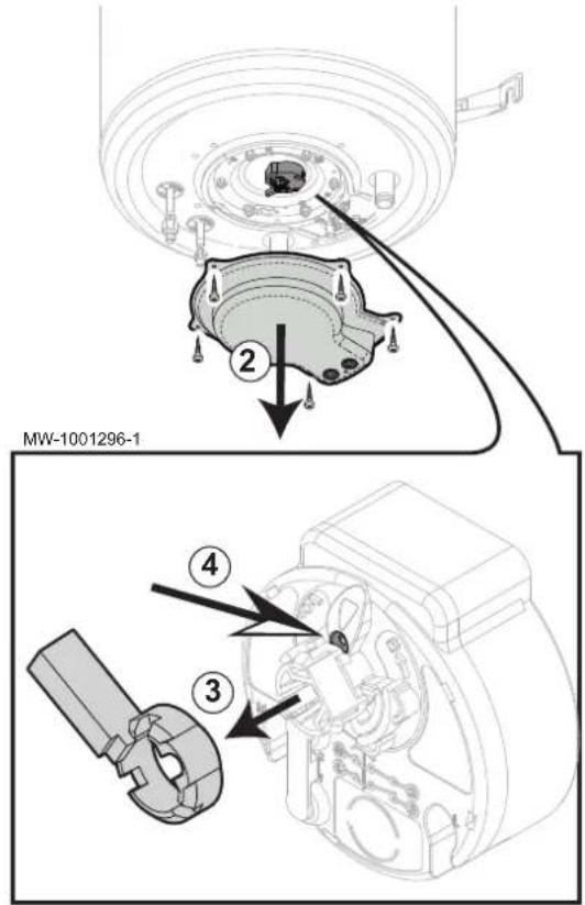
The thermostat is factory-set to 65 °C (average storage temperature). A thermal safety cut-out is integrated into the safety thermostat. It stops water from being reheated should accidental overheating occur. Remove the cause of the overheating and then reset the safety thermostat.
- Switch off the power supply.
- Remove the cover.
- Unclip the temperature adjustment lever to access the reset button.
- Using a suitable tool, push in the reset button.
11.2 Resolving error codes
Fig.55

If an error occurs, the control panel will display a key and a code The code is important for the correct and rapid diagnosis of the type of malfunction and for any technical assistance that may be needed.
- Make a note of the code displayed.
- Switch off the appliance.
- Switch the appliance back on.
⇒ The appliance starts up again autonomously when the reason for the disruption has been cleared. - If the error code is displayed again, correct the problem by following the instructions in the table below.

For more information, see
List of error codes, page 52
11.3 List of error codes
Tab.23 Ex-type error codes
| Code Description Causes and corrective actions | ||
| E2 | Communication error between the outdoor unit and the control panel | Check the connection between the outdoor unit and the control panel.Replace the control panel if necessary. |
| E4 | Water temperature sensor T5L error | Communication fault: check the connection.Damaged sensor: replace the sensor. |
| E5 | Evaporation temperature sensor T3 error | Communication fault: check the connection.Damaged sensor: replace the sensor. |
| E6 | Air temperature sensor T4 error | Communication fault: check the connection.Damaged sensor: replace the sensor. |
| E9 | Air suction temperature sensor Th error | Communication fault: check the connection.Damaged sensor: replace the sensor. |
| EA | Air discharge temperature sensor Tp error | Communication fault: check the connection.Damaged sensor: replace the sensor. |
Tab.24 Px type error codes
| Code Description | tion Causes and corrective actions | |
| P1 | High pressure error | Domestic hot water tank empty: fill the domestic hot water tank with water.Manual refrigerant valve closed: check the valve openings.Refrigeration tube pinched: check the refrigeration tubes.Excess refrigerant fluid: check the refrigerant fluid content.Non-condensables present: top up the refrigerant fluid.Water temperature sensor T5L poorly inserted in the sensor tube: check the positioning of the sensor T5L. |
| P2 | Electrical overconsumption error on the compressor | Domestic hot water tank empty: fill the domestic hot water tank with water.Manual refrigerant valve closed: check the valve openings.Refrigeration tube pinched: check the refrigeration tubes.Excess refrigerant fluid: check the refrigerant fluid content.Refrigerant fluid fault: check the refrigerant fluid content.Non-condensables present: top up the refrigerant fluid.Water temperature sensor T5L poorly inserted in the sensor tube: check the positioning of the sensor T5L. |
| P4 | Discharge temperature error: too high | Domestic hot water tank empty: fill the domestic hot water tank with water.Manual refrigerant valve closed: check the valve openings.Refrigeration tube pinched: check the refrigeration tubes.Excess refrigerant fluid: check the refrigerant fluid content.Refrigerant fluid fault: check the refrigerant fluid content.Non-condensables present: top up the refrigerant fluid.Water temperature sensor T5L poorly inserted in the sensor tube: check the positioning of the sensor T5 L. |
| bA | Air temperature information outside the operating limits | Air temperature outside the operating limits of the heat pump.The electrical back-up ensures the production of domestic hot water. |
| HC | Consumption error on the electrical back-upThe heat pump continues to operate but without electrical back-up | Consumption on the electrical back-up too low: check the connection of the electrical back-up.Consumption on the electrical back-up too high: check the immersion heater.If the set point temperature is greater than or equal to 65 °C: set the thermostat to maximum. |
| Code Description Causes and corrective actions | ||
| EF | Error on the main controller Main controller damaged: replace the main controller. | |
| JB | Frost protection running | Domestic hot water tank installed in a room exposed to frost: install the domestic hot water tank in a frost-free room.4-way valve blocked in cold mode: unblock or replace the 4-way valve. |
11.4 Clearing the error codes
If the probable cause of an error code is resolved, but the error code is still displayed:
- Clear the error code or codes by pressing keys and together for 3 seconds.
- Repeat the operation until the code or codes disappear.
11.5 Diagnosing errors on the outdoor unit
Fig.56

Only qualified persons may carry out diagnostics of the outdoor unit as the process is carried out directly on the outdoor unit.
- Switch the thermodynamic water heater off.
- Remove the top cover from the outdoor unit.
- Switch the thermodynamic water heater back on.

Danger
Electrified bare parts are then accessible.
- Scroll through the error codes by pressing the QUERY button.
- Refer to the list of error codes for the outdoor unit.
- Once troubleshooting is complete, put the top cover back on the outdoor unit.

For more information, see
List of error codes for the outdoor unit, page 54
11.6 List of error codes for the outdoor unit
Tab.25 Outdoor unit error codes
| Code no. Code description Complement | |
| 0 Normal display Water temperature T5L | • dF : Defrosting phase• dC : Refrigerant fluid recovery mode• 0: Holiday mode |
| 1 Mode 2: In residence | •8: Holiday |
| 2 Fan speed F0: Shut-down | •F1: Low speed• F2: High speed |
| 3 Evaporation temperature value T3 | |
| 4 Air temperature value T4 | |
| 5 Water temperature value T5L | |
| 6 Suction temperature value Th | |
| 7 Discharge temperature value Tp |
| Code no. Code description | Complement | |
| 8 Electrical current required:• to the electrical back-up,• to the compressor | ||
| 9 Degree to which the electronic pressure release valve is open | Open = value displayed x 8 | |
| 10 Set point temperature | Ts | |
| 11 Trip temperature of the electrical back-up Td | ||
| 12 Hysteresis Tr | ||
| 13 Last error code | ||
| 14 Software version | ||
| 15 End of parameters “_” | ||
12 Disposal and recycling
12.1 Switching the thermodynamic water heater off
Fig.57

- Power off the thermodynamic water heater before any interventions on the appliance.
- Disconnect the water supply to the domestic hot water tank.
- Drain the domestic hot water tank.
12.2 Disposing and recycling
Fig.58

The thermodynamic water heater must be dismantled and scrapped by a qualified professional in accordance with prevailing local and national regulations.
- Switch the thermodynamic water heater off.
- Recover the refrigerant from the installation.
- Dismantle the domestic hot water tank and the outdoor unit.
- Scrap or recycle the domestic hot water tank and the outdoor unit in accordance with local and national regulations.

For more information, see
Switching the thermodynamic water heater off, page 56
Recover the refrigerant fluid in the outdoor unit, page 48
13 Spare parts
13.1 Domestic hot water tank
Fig.59

Tab.26 Domestic hot water tank
| Markers Reference Description | |
| 1 7632380 150-I domestic hot water tank | |
| 2 89640516 Fastening clamp | |
| 3 7676762 Inspection hatch kit | |
| 4 7676763 Anode kit | |
| 5 95014035 Gasket ∅35 x 8.5 x 2 | |
| 6 94974527 Nylon spacer | |
| 7 99100577 Ground ring with lug | |
| 8 95013134 Lip gasket ∅112x7 | |
| 9 97525071 Clamp | |
| 10 97525072 Plate | |
| 11 7617252 Knurled screw H M5 x 10 | |
| 12 7650918 Earth wire | |
| 13 7659384 Thermostat | |
| 14 7676764 1600W immersion heater kit | |
| 15 7663109 EPDM dielectric gasket 45-36.5 x 4 | |
| 16 7665306 Spacer | |
| 17 7665308 Wire with 560Ω resistor | |
| 18 7622685 Stainless tube ∅16 L1440 | |
| 19 91590076 Tap nozzle | |
| 20 95310092 Corrugated ducting ∅16 | |
| 21 7622831 Complete cover | |
| 22 95320187 Cable clamp | |
| 23 95740600 EC-CB 3,5x25 screw | |
| 24 95320576 Grommet DG 13.5 | |
| 25 95890350 Nut PREST BG 3.9 | |
| 26 300025648 Dielectric union MF3/4" | |
| 27 7657646 L100 insulation | |
| 28 94902073 Drain valve 1/2" | |
| 29 7661699 Brass T-piece F3/4-F1/2-M3/4 | |
| 30 94950709 Black injection plug |
13.2 Outdoor unit
Fig.60

Tab.27 Outdoor unit
| Markers Reference | Description | |
| 1 7637563 Evaporator | ||
| 2 7637564 Protective handle | ||
| 3 7637565 Side panel | ||
| 4 7637567 Pressure release valve line | ||
| 5 7637568 4-way valve and pressure switch unit | ||
| 6 7637569 Stop valves support plate | ||
| 7 7637571 Base frame | ||
| 8 7637572 Gasket | under compressor | |
| 9 7637573 Gasket | support under compressor | |
| 10 7637574 Compressor | ||
| 11 7674792 Complete electronic box | ||
| 11.2 7674607 Control panel connection PCB | ||
| 11.3 7674606 Central unit PCB | ||
| 11.4 7637580 Transformer | ||
| 11.5 7637581 Compressor capacitor | ||
| 11.6 7637582 Fan capacitor | ||
| 12 7674608 Fan motor | ||
| 13 7637584 Protective grid | ||
| 14 7637585 Fan | ||
| 15 7637586 Side bracket | ||
| 16 7637587 Front panel | ||
| 17 7637588 Top panel | ||
| 18 7637589 Fan motor bracket | ||
| 19 7637590 Fan motor bracket plate | ||
| 20 7637591 Separation panel | ||
| 21 7637592 Control panel wall support | ||
| 22 7637593 Air temperature sensor | ||
| 23 7637594 Compressor suction temperature sensor | ||
| 24 7637595 Evaporator temperature sensor | ||
| 25 7637597 Compressor discharge temperature sensor | ||
| 26 7637598 Domestic hot water temperature sensor | ||
| 27 7674794 Control panel | ||
14 Appendix
14.1 Maintenance form for the installer
Tab.28 Maintenance carried out by the installer
| No. Operation Periodicity | ||
| 1 Check the | cleanliness of the outdoor unit fan once a year | |
| 2 Descaling | the domestic hot water tank after the first year of | useand then every twoyears |
| 3 Checking | the magnesium anode after the first year of | useand then every twoyears |
Tab.29 Maintenance carried out by installer no. 1: Date ____
| No. Remarks By Signature | |||
| 1 | |||
| 2 | |||
| 3 | |||
Tab.30 Maintenance carried out by installer no. 2: Date ____
| No. Remarks By Signature | |||
| 1 | |||
| 2 | |||
| 3 | |||
Tab.31 Maintenance carried out by installer no. 3: Date ____
| No. Remarks By Signature | |||
| 1 | |||
| 2 | |||
| 3 | |||
Tab.32 Maintenance carried out by installer no. 4: Date ____
| No. Remarks By Signature | |||
| 1 | |||
| 2 | |||
| 3 | |||
Tab.33 Maintenance carried out by installer no. 5: Date ____
| No. Remarks By Signature | |||
| 1 | |||
| 2 | |||
| 3 | |||
© Copyright
All technical and technological information contained in these technical instructions, as well as any drawings and technical descriptions supplied, remain our property and shall not be multiplied without our prior consent in writing. Subject to alterations.
CE

ELECTRICITE PERFORMANCE

BAXI
BAXI
Tel. +34 902 89 80 00
www.baxi.es
informacion@baxi.es



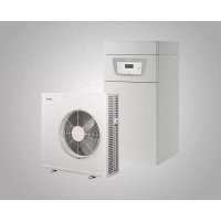
- Contents
- Safety 4
- Symbols used 12
- Technical specifications 13
- Description of the product 18
- Before installation....19
- Connecting diagrams 24
- Installation....30
- Safety
- General safety instructions
- Danger
- Danger of electric shock
- Important
- Warning
- Caution
- Recommendations
- Specific safety instructions
- R134a refrigerant
- Liabilities
- Manufacturer's liability
- Installer's liability
- Symbols used
- Symbols used in the manual
- Symbols used on the appliance
- Technical specifications
- Homologations
- NF certification
- EC Declaration of Conformity
- Electrical Conformity / CE Marking
- 2014/68/UE Directive
- Ecodesign Directive
- Technical data
- Technical data
- Sensor specifications
- Dimensions and connections
- Domestic hot water tank dimensions
- Outdoor unit dimensions
- Control panel dimensions
- Electrical diagram of the outdoor unit
- Electrical connection diagrams without external unit
- Electrical connection without off-peak/peak rate cables
- Electrical connection with off-peak/peak rate switch
- Installation
- Recommendations
- Install the appliances
- Installing the domestic hot water tank to the wall without a tripod
- Install the domestic hot water tank to the wall with a tripod
- Installing the outdoor unit
- ■ Installing the outdoor unit on the ground
- ■ Installing the outdoor unit on its wall bracket
- Installing the control panel support
- Hydraulic connections
- Preparing the water connections
- Connecting the domestic hot water tank to the cold water circuit
- Connecting the domestic hot water circuit
- Connecting the refrigeration connections
- Electrical connections
- Electrical recommendations
- Electrically connecting the outdoor unit
- Connecting the electrical connections of the domestic hot water tank with outdoor unit
- Connecting the electrical connections of the domestic hot water tank with no outdoor unit
- Connecting the control panel display
- Fill the domestic hot water tank.
- Commissioning
- Checklist before commissioning
- Initial commissioning
- Checklist after commissioning
- Setting the parameters
- Activate / Deactivate the Holiday mode
- Selecting the operating mode
- Set the temperature threshold for the electrical back-up function
- Setting the hysteresis for starting water heating
- Maintenance
- General
- Maintenance operation intervals
- Operate the safety valve or unit
- Maintenance of the outdoor unit
- Checking the cooling circuit
- Clean the fan and evaporator
- Recover the refrigerant fluid in the outdoor unit
- Maintenance of the domestic hot water tank
- Draining the domestic hot water tank
- Removing the inspection hatch
- Descaling the domestic hot water tank
- For more information, see
- Checking the magnesium anode
- ■ Visually checking the magnesium anode
- ■ Check the current of the magnesium anode
- Replacing the inspection hatch
- Checks after a disconnection of the mains supply
- Ordering spare parts
- Troubleshooting
- Resetting the safety thermostat
- Resolving error codes
- List of error codes
- Clearing the error codes
- Diagnosing errors on the outdoor unit
- List of error codes for the outdoor unit
- Disposal and recycling
- Switching the thermodynamic water heater off
- Disposing and recycling
- Spare parts
- Domestic hot water tank
- Outdoor unit
- Appendix
- Maintenance form for the installer
- © Copyright
Brand : Baxi
Model : BC ACS Split
Category : Heat pump