
MIC440 - Surveillance Camera BOSCH - Free user manual and instructions
Find the device manual for free MIC440 BOSCH in PDF.


| Type de produit | Surveillance Camera |
| Brand | Bosch |
| Model | MIC440 |
| Camera Type | PTZ Dome |
| Resolution | Up to 1080p (1920x1080) at 30 fps |
| Optical Zoom | 10x |
| Pan Range | 360° continuous |
| Tilt Range | -90° to +90° |
| Protection Rating | IP66 |
| Operating Temperature | -40°C to +55°C |
| Power Supply | PoE+ (IEEE 802.3at) or 24V AC |
| Power Consumption | 25W max |
| Weight | 3.5 kg |
| Dimensions | 200 x 200 x 300 mm |
| Sensor | 1/2.8" CMOS |
| Night Vision | IR up to 50m |
| Video Compression | H.264, H.265 |
| Audio | Bidirectional audio |
| Maintenance | Clean dome with soft dry cloth |
| Security | Password protection, encryption |
| Spare Parts & Repairability | Available via Bosch service |
| Warranty | 2 years |
| Compatibility | ONVIF Profile S & T, Bosch VMS |
Frequently Asked Questions - MIC440 BOSCH
User questions about MIC440 BOSCH
0 question about this device. Answer the ones you know or ask your own.
Ask a new question about this device
Download the instructions for your Surveillance Camera in PDF format for free! Find your manual MIC440 - BOSCH and take your electronic device back in hand. On this page are published all the documents necessary for the use of your device. MIC440 by BOSCH.
USER MANUAL MIC440 BOSCH
MIC440 Explosion Protected CCTV Camera System
Bosch Security Systems
EN | Installation and Operation Manual

BOSCH
MIC440 Explosion Protected CCTV Camera System
Installation and Operation Manual
For the MIC440 Camera System
Chapters
- Introduction
- Hardware Installation
- Power Supply Installation & Setup
- Configuring the MIC440 Camera
- Technical Specifications
MIC440 Explosion Protected CCTV Camera System | Installation and Operation Manual
EN | 3
Introduction.... 1-6
MIC440 Camera Options.... 1-7
MIC440 Power Supply Versions.... 1-7
Unpacking.... 1-8
Package Contents.... 1-8
Installation Accessories.... 1-9
Hardware Installation.... 2-10
Preinstallation Preparation in the Workshop.... 2-11
Cable Gland and Cable Mounting Instructions.... 2-11
Camera Installation Instructions.... 2-11
Electrical Connections to the MIC440.... 2-12
Earthing Instructions.... 2-13
Lightning Protection.... 2-13
Maintenance.... 2-13
Onsite Inspection.... 2-13
Power Supply Installation and Setup.... 3-14
Hazardous Area Power Supply Installation.... 3-14
Diagrams of example Hazardous Area Installations.... 3-15
Non Hazardous area Power Supply Installation.... 3-16
Connecting the MIC-240, MIC-24 and MIC115PSU.... 3-17
Power Supply Layout and Connections 3-18
PCB Earth Link.... 3-18
Fuse Ratings.... 3-18
MIC-12PSU 3-19
MIC-12PSU Power Supply Layout and Connections.... 3-19
Optional Cards and Kits for the MIC440 3-20
Configuring the MIC440 Camera.... 4-20
Connecting the MIC440 to a PC.... 4-20
Connecting the Greenwich adaptor.... 4-20
Connecting the K2-ADE Adaptor 4-21
Connecting the MIC-USB485 Converter.... 4-22
MIC-USB485 Converter and Universal Camset Software Installation. 4-22
Commissioning the MIC440 camera with Universal Camset.... 4-23
Standard Controls.... 4-23
Boot Messaging 4-24
MIC Settings 4-24
Camset Settings.... 4-25
Manual Control 4-26
Pan, Tilt and Zoom Controls.... 4-26
Iris Controls.... 4-26
Focus Controls 4-26
Auxiliaries.... 4-27
Preset Positions.... 4-27
Tour Controls 4-28
Softstops and No Dwell Zones 4-28
MIC Setups 4-29
General Settings.... 4-29
AutoHome Controls 4-30
Other Controls 4-31
Default Settings 4-31
MultiAlarm Settings 4-32
Lens Recalibration and Frame Integration 4-33
Privacy and Captions 4-33
Privacy Controls.... 4-34
Captions 4-35
Thermal 4-36
Advanced Settings 4-37
MIC Serial Number 4-37
EEPROM Copier 4-38
Re-Map Auxiliary (Pelco Protocol Only) 4-38
Menu Control (Panasonic Protocol Only) 4-39
Matrix Controls 4-39
POT Test 4-39
POT Test Controls 4-40
POT Test Results 4-41
Comms 4-41
Send Direct Command.... 4-42
Communications Testing.... 4-42
SonySet.... 4-43
SonySet Controls 4-44
The SonySet Table 4-45
MIC Programmer.... 4-46
Technical Specifications.... 5-47
Technical Specifications 5-47
Safety Precautions
The following symbols are used throughout this manual; please pay careful attention to their meaning.

The lightning flash with an arrowhead symbol within a triangle is intended to alert the user to the presence of non-insulated "dangerous voltage" within the product's enclosure that may be of sufficient magnitude to constitute a risk of electric shock to persons.

The exclamation point within a triangle is intended to alert the user to the presence of important safety, operating and maintenance (servicing) instructions in the literature accompanying the appliance.
Important Safety Instructions

CAUTION
TO REDUCE THE RISK OF ELECTRICAL SHOCK, DISCONNECT POWER SUPPLY BEFORE OPENING THE POWER SUPPLY UNIT. POWER DISCONNECT: POWER SUPPLY UNITS HAVE POWER SUPPLIED WHENEVER THE POWER CORD IS INSERTED INTO THE POWER SOURCE

WARNING
INSTALLATION SHOULD BE CARRIED OUT BY QUALIFIED PERSONNEL ONLY IN ACCORDANCE WITH THE APPLICABLE LOCAL CODES. BOSCH SECURITY SYSTEMS ACCEPT NO LIABILITY FOR ANY DAMAGES OR LOSSES CAUSED DUE TO INCORRECT OR IMPROPER INSTALLATION
IMPORTANT SAFETY INSTRUCTIONS
- Read and keep these instructions
- Heed all warnings and follow all instructions
- Do not install near any strong heat sources such as furnaces
- Do not back-drive the pan or tilt axis of the camera. To do so will damage the motor drive gear chain and will invalidate the warranty
- Do not use caustic or abrasive cleaning products on the unit
- Do not point the MIC440 camera at the sun. BOSCH Group will not be liable for any damages to cameras which have been directly pointed at the sun
- In situations where there could be a risk of injury should any part of the assembly become detached for any reason and fall, normal common sense safety precautions should be employed; a strong safety chain between the camera pan shaft and the mounting surface is recommended.
- For transportation, please rotate the ball so the window points towards the base. This helps to protect the wiper and windows during transit.
- Ensure that the product case is properly earthed. If the product is likely to be struck by lightning, ensure that earth-bonding connections are made correctly to the mounting base of the unit.
- Use only the power sources indicated in this user guide and ensure that the current rating of supply cables, fuses, and overload protection devices are adequate for the product.
- The product is certified for use within the ambient temperature range of -20°C to +60°C and must not be used outside this range.
- This product must only be installed by suitably trained personnel in accordance with the relevant code of practice (e.g., EN60079-14:1997). These instructions are intended for their sole use.
- All installation work should be carried out in accordance with the relevant local and national standards. The unit shall only be installed and brought into service using the operating parameters defined in these instructions and in the technical specifications.
- There are no user serviceable parts and on-line maintenance is not required for this product.
- Inspection and maintenance of this equipment must be carried out by suitably trained personnel in accordance with the applicable code of practice e.g. EN 60079-17.
- Repair of this equipment must be carried out by suitably trained personnel in accordance with the applicable code of practice e.g. EN 60079-19.
- Units must carry the following certification marking. SIRA05ATEX1300X Exd IIC T6 Ta -20°C to +60°C Gb

WARNING NO REPAIRS REQUIRING OPENING THE PRODUCT CASING WHILST IN A HAZARDOUS AREA ARE ALLOWED. FAILURE TO OBSERVE THIS PRECAUTION WILL VOID THE CERTIFICATION AND WARRANTY. BOSCH SECURITY SYSTEMS ACCEPTS NO LIABILITY FOR LOSSES CAUSED BY INCORRECT INSTALLATION OR MISUSE OF THE PRODUCT
Please contact BOSCH Security Systems for details of approved repair centres.
This product complies with the following EC directives:-
EMC Directive (89/336/EC as amended)
Machinery Directive (98/37/EC)
LV Directive (73/23/EC)
RoHS (Restriction of Hazardous Substances) 2002/95/EC
WEEE (Waste Electrical & Electronic Equipment) 2002/96/EC

This equipment contains electrical or electronic components that must be recycled properly to comply with Directive 2002/96/EC of the European Union regarding the disposal of waste electrical and electronic equipment (WEEE). Contact your local supplier for procedures for recycling this equipment.
This product is designed for use with flammable gases and vapors covered by apparatus groups IIA, IIB and IIC and with temperature classes T1 to T6.
Reference
Glossary of Terms
PTZ - Pan/Tilt/Zoom
Bi-phase - Bosch Bi-phase telemetry protocol
PSU - Power Supply Unit
IR - Infra Red
BP 4 - Bi-phase converter cards for MIC400 cameras
STP - Shielded Twisted Pair cable
Glossary of Tables
Table A (Pg7) - Flamepath Tolerance table
Table B (Pg12) - MIC composite cable pin table
Table C (Pg18) - Power connection to Header HD1
Table D (Pg18) - Composite cable to Power Supply HD-3
Table E (Pg18) - Telemetry Connections to HD3, HD4 and HD5
Table F (Pg18) - Fuse ratings for MIC-240PSU, MIC-24PSU, MIC-115PSU
Table G (Pg19) - Power Input wiring connections for MIC-12PSU - HD1
Table H (Pg20) - Connecting the Greenwich Adaptor
Table I (Pg21) - DIP Switch Settings for K2-ADE 2 wire mode
Table J (Pg21) - K2-ADE Adaptor Connection
Table K (Pg21) - Camera Interface Control Settings
Table L (Pg22) - MIC-USB485CVTR Connection table and Diagram
Table M (Pg45) - Sony Set Commands
Appendices
Appendix A (Pg49) - Protocol Preset Commands
CHAPTER 1 Introduction
The MIC440 is a complete PTZ camera head system specifically designed for use in hazardous areas and is rated up to IIC T6 classification. The robust construction in aluminium makes it ideally suitable for the petrochemicals industry and other demanding environments.
The unit is designed to be plug and play making it easy to install, giving considerable reductions in installation and maintenance costs.
To bring the unit into service, use only assembling, and adjustment equipment as described in the text and diagrams contained in this instruction manual.
The certification of this equipment depends upon the maintenance of the flamepaths (see note and table) and the use of the following materials in the construction.
The maximum constructional gaps (Ic) of the cylindrical flamepaths are less than that required by Table A of EN 60079-1:2007, as detailed below:
The pan body to pan body top are to be secured with cap head M5 - 0.8 x 10 mm long S316 stainless steel grade A4/70 special fasteners.
All exposed parts: Aluminium (BS-EN755 1997 6082T6)
Stainless Steel (BS-EN10088 No.1.4404)
If the equipment is likely to come into contact with aggressive substances, then it is the responsibility of the user to take suitable precautions to prevent it from being adversely affected, thus ensuring that the type of protection provided by the equipment is not compromised.
Aggressive substances: e.g., acidic liquids or gases that may attack metals, or solvents that may affect polymeric materials.
Suitable precautions:
e.g., regular checks as part of routine inspections or establishing from the material's data sheets that it is resistant to specific chemicals.
Units must carry the following certification marking.
SIRA05ATEX1300X Exd IIC T6 Ta -20°C to +60°C Gb
Table A - Constructional Flamepath Tolerances
| Flamepath Maximum | Gap (mm) |
| Between the tilt centre bore and tilt bearing housing shaft (2 off) 0.089 | |
| Between the yoke arm bore and tilt resolver shaft. 0.061 | |
| Between the yoke arm bore and yoke arm blanking cap shaft. 0.061 | |
| Between the yoke arm bore and yoke spigot shaft | 0.061 |
| Between the pan body top bore and yoke spigot shaft (2 off) | 0.061 |
| Between the upper cover bore and wiper motor mount shaft. | 0.060 |
| Between the wiper motor mount bore and base flange shaft. | 0.100 |
MIC440 Camera Options
The MIC440 Camera has the following optional extras available:
MIC-ALM - 8 input Alarm card (Fits in PSU).
MIC-WKT - Washer pump drive card (fits in MIC-PSU), washer
nozzle and bracket.
MIC-BP4 - Bosch Bi-phase converter card for power supplies with an expansion slot available.
MIC440 Power Supply Unit Versions

CAUTION: The PSU enclosures are not Exd rated and must be replaced with a certified enclosure if installed within a hazardous area.
Bosch Security Systems has designed a range of power supplies for the MIC440 camera to cater for a variety of common voltages and provide all the connections needed for power, telemetry and video. The power supply units and options are detailed below.
MIC-240PSU - 240Vac input Power Supply Unit
MIC-115PSU - 115Vac input Power Supply Unit
MIC-24PSU - 24Vac Input Power Supply Unit
MIC-12PSU - 12 to 24Vdc Input Power Supply Unit
Unpacking

CAUTION: Take extra care lifting or moving MIC440 units due to their weight.
- Check the exterior of the packaging for visible damage. If any items appear to have been damaged in transit please inform the shipping company.
- Unpack the power supply unit carefully; although ruggedized this is electronic equipment & should be handled with care.
- Do not use if any component appears to be damaged. Please contact Bosch Security Systems in the event of damaged goods.
- The shipping carton is the best way to transport the unit; save it and all other packaging materials for future use. If the unit must be returned, use the original packing materials.
Package Contents
Please check for the following contents:
• MIC440 Installation & Operation manual (this guide) • Installation & Configuration CD - Quick start reference sheet
MIC440 Explosion Protected CCTV Camera System Installation and Operation Manual
EN | 9
Installation Accessories

CAUTION: Ensure all local safety codes are observed when installing this product; ensure a strong safety chain is used to secure the MIC440 camera to prevent any danger of dropping the product during installation. Particular care should be taken with MIC440 models due to the additional weight.
The MIC440 Camera has been designed to be easily installed on a variety of common fittings. The MIC440 comes with an integrated Deep Conduit Adaptor with an M20 threaded hole for a suitable Exd cable gland (not supplied).
The MIC440 cameras can be mounted on lamp post column/scaffolding pole or similar using the Pole Mount Bracket (MIC-PMB); however, users should be aware that lamp posts can often be subject to movement and are not suitable platforms in all conditions or for all applications.
For mounting directly onto buildings, Bosch Security Systems manufactures a range of brackets suitable for all typical building installations for upright (90°) or inverted camera positions. Examples are shown below.
MIC-CMB - Corner Mount Bracket
MIC-WMB - Wall Mount Bracket
MIC-SCA - Shallow Conduit Adaptor
MIC-DCA - Deep Conduit Adaptor (Included)
MIC-PMB - Pole Mount Bracket

CAUTION: For additional protection in hazardous area installations, suitable flexible conduit can be used externally for the composite cable run to connect the power supply to the Exd Cable Gland (not supplied) in the MIC440 Deep Conduit Adaptor.


Key to MIC-PMB drawing
- Securing bolts for MIC-SCA
- 90mm stainless steel pole banding
- Pole mount bracket blocks
- Pole mount bracket plate
- Pole mount block securing bolts
- Shallow conduit adaptor
- "O"-ring
- Wall mount bracket
- Wall mount bracket securing bolts
CHAPTER 2 Hardware Installation

CAUTION: Ensure all local safety codes are observed when installing this product; ensure a strong safety chain is used to secure the MIC440 camera to prevent any danger of dropping the product during installation.
This product is designed for use with flammable gases and vapors covered by apparatus groups IIA, IIB and IIC and with temperature classes T1 to T6.
The product is certified for use within the ambient temperature range of -20°C to +60°C and must not be used outside this range.
This product must only be installed by suitably trained personnel in accordance with the relevant code of practice (e.g., EN60079-14:1997). These instructions are intended for their sole use.

The MIC440 uses a composite cable to carry all power and telemetry between the camera head and the MIC power supply unit. This cable can be a maximum of 25m long. For installations which require the camera head to be more than 25m from the power supply, it is recommended that a 2m cable be connected to an Exd rated junction box from which telemetry, video, and power can be broken out into separate cables with appropriate wiring to extend the distance to suit.

CAUTION: Any junction box or enclosure used for mounting the power supply or separating cable cores must be Exd rated to the appropriate rating for the installation.
CAUTION: If the camera is mounted ball down, it is essential that the connector and base area of the camera are completely sealed from water ingress.

CAUTION: Any water getting into the connector is liable to cause corrosion to the connector pins, leading to unreliable operation of the camera unit.
Pre-installation Preparation in the Workshop
The unit is NOT supplied with an external Exd cable gland. A suitable sized Exd barrier gland to match the composite cable diameter is required. For the Bosch composite cable (8mm), use a Hawke cable gland type 501/421 Size 0.
The composite cable is required to connect the MIC440 to its power supply. It consists of two pairs (24AWG) plus 4 cores of (22 AWG), 2 cores of (24 AWG), and one coax core for the video signal, to a maximum distance of 25m as per Table B.

CAUTION: It is recommended that the cable and connector should be made up, connected to the unit, and sealed with the Exd barrier gland in a workshop before taking the unit for mounting on site.
All connections to the unit are made via the single 12-way connector mounted on the base of the camera unit and accessible through the base conduit adaptor.
Cable Gland and Cable Mounting Instructions
- Remove the 4 x M8 Hexagon bolts holding the base conduit adaptor to the MIC440 unit and remove the base conduit adaptor.
- Fit the composite cable through the Exd barrier gland.
- Fit the composite cable through the 20mm threaded gland hole in the base conduit adaptor and allow approx 100mm of free cable on the inside to connect to the 12-way cable connector.
- Screw the Exd barrier gland into the base conduit adaptor, maintaining approximately 100mm of cable on the inside of the adaptor to enable the cable connector to be freely inserted into the MIC unit base connector.
- Connect the 12-way cable connector into the matching connector in the base of the MIC unit.
- Make sure the connector is fitted home properly in the camera integral plug (requires approximately two and a half turns of the socket threaded ring to fasten the two halves of the connectors together properly).
- Fit the base conduit adaptor back to the MIC440 unit and fasten using the 4 x M8 hexagon bolts.
- Ensure that there are no trapped cables.
- Ensure there is some slack cable in the base conduit adaptor, then tighten up and seal the Exd barrier gland as per the instructions included with the gland.
- The unit with the cable tail is now ready for on-site installation.
Camera Installation Instructions
- Locate the mounting position of the camera so that it cannot be interfered with either intentionally or accidentally.
- Ensure the mounting surface is capable of supporting the combined weight of the camera and mounting hardware under all expected conditions of load, vibration, and temperature.
- Fit the mounting brackets (if used) securely, observing all appropriate safety precautions and local building regulations.
- Earth the camera using one of the securing bolts. Only earth the camera at a single point to prevent earth loops and hum bars.
- M8 x 20mm stainless steel nuts, bolts, and washers should be used to secure the camera's base conduit adaptor to the mounting point.
- Secure all cabling and conduit.
MIC440 Explosion Protected CCTV Camera System Installation and Operation Manual
EN | 12
Electrical Connections to the MIC440
The MIC440 base connector pin allocations are as follows:
Table B - MIC Connector Pin Table
| Connector Pin Signal Name | Description Cable Wire | Type/Colour | |
| A Video | Output | Video Signal output to control room | Coax core |
| B Video | Return | Video Signal Ref output to control room | Coax screen |
| C Tamper | Switch | Connection C to D will provide an alarm to the control | 24 AWG core- Black |
| D Tamper | Switch return | room via telemetry 24 AWG core | - Brown |
| E Washer | drive return | TTL ref output can be used to drive external relay for wash operation option | 22 AWG core- Grey |
| F Washer | drive | TTL output can be used to drive external relay for wash operation option | 22 AWG core- Orange |
| G Full Duplex | Tx A | Telemetry Output RS 485 Pair 1 - Blue | |
| H Full Duplex | Tx B | Telemetry Output.RS485 Pair 1 - Violet | |
| J Full Duplex | Rx AHalf DuplexTx/Rx A | Telemetry I/O to RS485 Pair 2 - Yellow | |
| K Full Duplex | Rx BHalf DuplexTx B | Telemetry I/O to RS485 Pair 2 - White | |
| L Power input | 1 | Low volt AC or DC power input 15 Volts AC or DC | 22 AWG core - Red |
| M | Power input 2 | Low volt AC or DC power input 15 Volts AC or DC | 22 AWG core - Green |
Video output signal conforms to CCIR PAL 1V Composite format. (NTSC format is available on request).
Telemetry signals all conform to the RS485 / RS422 standard.
The unit continuously monitors incoming telemetry whether in full or half duplex mode.
In full duplex mode, the Tx pins are tri-state except during transmission times. This may cause problems when interfacing to some Fibre Optical converter units. Check out the Commissioning notes for ways of overcoming these problems. In 2 wire Half Duplex mode (RS485), the Rx Pins are used to transmit data to the MIC440 unit.
The washer connections can be used to operate a relay in the power supply unit, which in turn can activate a pump.
Earthing of the MIC440 Camera
- The camera module and housing are electrically isolated so the housing should be safety earthed regardless. The safety earth should be a bonding connection to the camera's outside case, for example one of the securing bolts.
- The camera should be earthed at one point only to prevent earth loops and thus hum bars showing on the control room monitor.
- If the system is copper throughout and the camera pictures are fed back to the control room via coaxial copper cable, then the camera should be earthed at the video termination point in the control room and nowhere else. In this case the PCB "Earth Link" should be broken.
- If the video is transmitted back to the control room via some non-electrical connecting medium, e.g. fibre optic, radio or microwave link, then the camera should be earthed at the transmitter point in the PSU. The PSU "Earth Link" may be used for this purpose.
- If dual earthing is unavoidable then a video isolation transformer should be fitted between the two earths.
Lightning Protection
If the camera is fitted in a highly exposed place then consideration should be given to lightning protection. A good earth bonding connection to the case itself will provide protection against damage from secondary strikes.
Where there is a risk of a primary strike hitting the camera housing directly, it is recommended that a separate lightning conductor be fitted within 0.5m of the camera and at least 1.5m higher than the camera.
The construction of the housing itself is very capable of coping with secondary strikes and no damage to the internal electronics or camera should result if correct lightning protection is applied.
Maintenance
The unit contains no maintainable parts and in the event of failure should be removed from site for repair. Maintenance and repair of this equipment shall only be carried out by suitably trained personnel in accordance with the applicable code of practice (e.g. EN60097-19)
To maintain the validity of the certification only components supplied by Bosch Security Systems shall be used.
On Site Inspection
It is recommended that the equipment be inspected on site every six months to check mounting bolts for tightness, security and any signs of physical damage. Inspection of this equipment shall only be carried out by suitably trained personnel in accordance with the applicable code of practice (e.g. EN60097-17)
CHAPTER 3 Power Supply Installation & Setup
The Power Supply Units provide all the support functions for connecting the MIC440 cameras to third party equipment, they comprise of the following products:
MIC-12PSU, MIC-240PSU, MIC-24PSU and MIC-115 PSU
The power supply provides power for a single MIC440 camera unit from a 12v DC source (MIC-12PSU), a 240v AC source (MIC-240PSU), a 24v AC source (MIC-24PSU) or a 115v AC source (MIC-115PSU). The transformer fitted to these designs is thermally protected and automatically cuts out if the transformer core temperature exceeds 40 Degrees C. On cooling the transformer will become operational again.
In addition, the unit provides all the terminations required to connect a MIC440 camera to third-party equipment.
A second independent 12V (600mA) power supply is also included to drive any internally fitted optional interface cards.
Hazardous Area Power Supply Installation Instructions

CAUTION: The PSU enclosures are not Exd rated and must be replaced with a certified enclosure if installed within a hazardous area. This product must only be installed by suitably trained personnel in accordance with the relevant code of practice (e.g., EN60079-14:1997).
Installation of the PSU within a hazardous area must have the standard PSU enclosure replaced with an appropriate certified enclosure and four (4) Exd cable glands (NOT supplied). The power supply PCB is usually re-housed by a third-party company within an Exd enclosure, which is then factory certified and shipped to site. Follow all manufacturer's instructions when installing a third-party Exd enclosure; examples are shown on Page 15.
A maximum cable length of 25m is permitted as shown overleaf in Fig A. If the PSU can be located in a non-hazardous area near the camera installation, then an Exd enclosure for the PSU may not be required, as shown in Figure B on page 15.

Figure A - Installation using Exd junction box


Non-Hazardous Area Power Supply Installation Instructions

WARNING: Electrical Danger: Ensure all power is disconnected before opening or working upon any Power Supply Unit. Installation must be carried out by suitably qualified persons, and all local safety regulations should be followed.
Figure B - Installation of the PSU in a Non-Hazardous area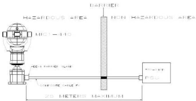
Installation of the MIC-PSU
To install the MIC-PSU in a non-hazardous area, please do the following.
- Locate the mounting position of the MIC-PSU outside the hazardous area so that it cannot be interfered with either intentionally or accidentally; a lockable cabinet is recommended.
- Securely fix the MIC-PSU using M4 stainless steel screws and washers; ensure the cable glands have sufficient room to allow for the cables to enter.
- Feed all cabling through the appropriate sized gland holes.
- Connect the composite cable to HD3 following the colour coding as shown in Table D and printed on the PCB.
- If a tamper switch relay is to be used, connect this at HD2.
- Connect the Coaxial video cable to the CN1 header.
- CN2 is for additional add-on cards such as alarm inputs, video processors, Bi-phase cards etc.
- Telemetry connections are provided by headers HD3, HD4 and HD5 which respectively enable crimp or screw terminations for connecting the MIC440 to the control room as per Table E.
- Connect the power to HD1 carefully observing the polarity and voltage as per Table C.
- When wiring is complete, apply power and check that all four (4) LEDs are lit.
- Following installation, when power is applied, the following LEDs will light to indicate:
LED1 - 15VAC power on to camera
LED2 - 15VAC power on to camera
LED4 - Power on for optional heater/speaker (not MIC440)
LED5 - Power on for optional heater/speaker (not MIC440)
- Re-attach the enclosure lid and screw down until tight.
- For installation of the MIC-WKT-KIT, MIC-ALM, or MIC-BP-4 Bi-phase card, please refer to their respective manuals.
Connecting the MIC-24PSU, MIC-240PSU, or MIC-115PSU
Once installed on site, please connect the composite cable from the MIC440 to the MIC-PSU as per the following instructions.

WARNING: Electrical Danger: Ensure all power is disconnected before opening or working upon any Power Supply Unit. Installation must be carried out by suitably qualified persons, and all local safety regulations should be followed.
The Power Supply Unit comprises of the following:
1) A weather resistant (IP55) plastic box fitted with four cable glands. 2) A power supply for the MIC440 camera. 3) A second power supply for driving various interface cards mounted internally to the power supply box. e.g. washer drive card, alarm interface card. 4) Provision for a signal interface card, to connect telemetry to third party equipment. 5) Screw termination of all cable into and out of the box. 6) Correct video termination for the camera coaxial cable. 7) Earth isolation and termination within the unit to correctly control Video earthing and thus prevent Earth loop.
Power Supply Layout and Connections
The Power supply PCB has the following connections as shown overleaf on Figure C:-
HD1 - Power Input Connector (screw terminal) HD2 - Tamper Switch header (screw terminal) HD3 - Composite cable header (Connections to camera head, screw terminal) HD4 - Telemetry header (Molex Connection) HD5 - Telemetry header (screw terminal) HD6 - Washer pump header (screw terminal) HD8 - Keyboard power connector (demo purposes only, not normally fitted) CN1 - Video out connection header (BNC) CN2 - Add on card header (plug in)
Dimensions
Power supply enclosure:-225mm (W) x 70mm (H) x 195mm (D)
Figure C - MIC24PSU/MIC-240PSU/MIC-115PSU Layout
PCB Earth Link
The PCB has one link option next to HD1 to allow the power supply to be set up for different earthing schemes: The Earth Link should be broken if there is a separate connection between video screen and earth. Usually occurs on copper connected systems where all the copper video coaxes are taken back to the control room to be connected to a central earth point. If fibre optics or other indirect connections are used to get data and video to and from the control room then the earth link should be left intact provided it is the only camera end earth reference point.
Table C - Power Connection to Header HD1
| Live | HD1-1 |
| Neutral | HD1-2 |
| Earth | HD1-3 |
Table D - Composite cable to Power Supply HD-3 Connection Table
| Composite Cable Wire Colour | Function Terminal Box Connector | Terminal Box ID Marking | |
| Red AC supply HD3-1 Power | |||
| Green AC supply rtn. HD3-2 Power | |||
| White Rx + | HD3-3 RxB | ||
| Yellow Rx - | HD3-4 RxA | ||
| Drain Wire | Gnd | HD3-5 | GND |
| Blue | Tx - | HD3-6 | TxA |
| Violet | Tx + | HD3-7 | TxB |
| Coax Core | Video | HD3-8 | Video |
| Coax Screen | Video Return | HD3-9 | Vid 0v |
| Black (Optional) | Tamper Switch | HD3-10 | Tamp Sw |
| Orange (Optional) | Wash drive | HD3-11 | Wash |
Table E - Telemetry Connections to HD3, HD4 and HD5
| Telemetry Signal Name | HD3 | HD4 | HD5 |
| RXB or Rx + | Pin 3 | Pin 1 | Pin 1 |
| RXA or Rx - | Pin 4 | Pin 2 | Pin 2 |
| GND | Pin 5 Pin 3 | Pin 3 | |
| TXA or Tx - | Pin 6 | Pin 4 | Pin 4 |
| TXB or Tx + | Pin 7 Pin 5 | Pin 5 |
Fuse ratings
The power supply houses 4 off 20mm fuses in fuse holders. The ratings for these fuses are fixed on the low voltage secondary side but change with input voltage on the high voltage primary side.
The following table shows the fuse values fitted for the different supplies for operating the power supply: Note FS 4 does not exist
Table F - Fuse Ratings for MIC-240PSU, MIC-24PSU and MIC-115PSU
| Fuse ident | Fuse function. | Rating for 240v primary | Rating for 115v primary |
| FS 1 | MIC400 protection | 1.6A glass Anti surge (T) | 1.6A glass Anti surge (T) |
| FS 2 | Primary protection. | 800mA ceramic quick blow | 800mA ceramic quick blow |
| FS 3 | Heater protection 1 | 1.6A glass Anti surge (T) | 1.6A glass Anti surge (T) |
| FS 5 | Heater protection 2 | 1.6A glass Anti surge (T) | 1.6A glass Anti surge (T) |
MIC-12PSU Power Supply Unit
The power supply provides power for a single MIC440 camera unit from a 9V DC to 29V DC source for installations using low voltage systems.
Dimensions
Power supply enclosure - 225mm (W) x 70mm (H) x 195mm (D)
This is connected as per the MIC-240PSU as shown previously with the exception of the following changes:-

WARNING: Electrical Danger: Ensure all power is disconnected before opening or working upon any Power Supply Unit. Installation must be carried out by suitably qualified persons & all local safety regulations should be followed.

CAUTION: It is extremely important to observe the correct polarity, failure to do so will result in the destruction of the DC-DC power supply. CAUTION: This power supply was designed for negative earthed systems only it is not suitable for use with positive earth systems.
This should be fed in to connection HD1 nominally marked as mains input, connections should be as follows:-
Table G - Power Input wiring connections for MIC-12PSU
| Positive HD1-1 | |
| Negative HD1-2 | |
| Earth and Negative HD1-3 | |

WARNING: The rating of fuse FS2 should be changed to a 2A quickblow as opposed to the rating shown on the PCB.
Power Supply Layout and Connections
HD1 - Power Input Connector (screw terminal)
HD2 - Keyboard power connector (demo purposes only, not normally fitted)
HD3 - Composite cable header (Connections to camera head, screw terminal)
HD4 - Telemetry header (Molex Connection)
HD5 - Telemetry header (Screw terminal)
HD6 - Tamper Switch header (Screw terminal)
HD7 - Washer Pump Drive header (Screw terminal)
CN1 - Video out connection header (BNC)
CN2 - Add on card header (plug in)
Figure C - MIC-12PSU Layout
For 12V Installations the composite cable wiring is identical to that shown earlier in this manual on Table D.
MIC440 Explosion Protected CCTV Camera System Installation and Operation Manual
EN | 20
Optional Cards and Kits for MIC440 Cameras
The MIC440 has several optional cards and kits as described earlier.
Please refer to the respective manuals for details on their installation and operation.
MIC-WKT Washer bracket, nozzle and pump card kit
MIC-ALM 8-Input alarm card includes washer pump drive function
MIC-BP4 Bosch Bi-phase converter card for MIC power supplies with an available expansion slot.
CHAPTER 4 Configuring the MIC440 Camera
Connecting the MIC440 to the PC

CAUTION: This procedure must be carried out in a non-hazardous area only.
The MIC can be connected to a PC's serial port via a RS232/RS422 adaptor unit; this will generally be assigned to Comm Port 1.
Suitable serial port adaptor units are the Greenwich RS232/RS422 adaptor unit (Farnell 778-758, RS No: 201-758), the KK systems K2-ADE RS232 to RS485/422 adaptor or the MIC-USB485CVTR (485 to USB Converter) for PC's without a serial port.
Connecting the Greenwich Adaptor
To connect the Greenwich serial adaptor to the PC you will also need a 9 pin D female to 25 pin D male RS232 compatible adaptor cable. A suitable cable is Farnell 960-573 or RS Part No: 202-644. The adaptor should be set to DCE mode and the power supply connected.
Connections from the Greenwich adaptor to the power supply are shown below
Table H - Connecting the Greenwich Adaptor
| Adaptor Connections HD4 | |
| F 778-758. Connection and wire colour. | |
| DATA OUT 6-3+ RXB White | |
| DATA OUT 5-4- RXA Yellow | |
| SCREEN 0v | |
| DATA IN 4-5- TXA Blue | |
| DATA IN 3-6+ TXB Violet | |
MIC440 Explosion Protected CCTV Camera System Installation and Operation Manual
EN | 21
The connections can be tested by selecting the DETECT button in Camset and checking to see if the window below this button displays the address and software version number of the camera being tested.
Should a problem be encountered, then connect the MIC440 screen wire (0V) to the PC chassis with a separate piece of wire to ensure 0V continuity.
Connecting the KK Systems K2-ADE RS232 to RS485/422 Adaptor
This unit is self-powered and can be plugged directly into the PC serial port. RS485 two-wire mode.
Connections and DIP switch settings for 2-wire mode should be made as follows:
Table I – DIP Switch Settings for K2-ADE 2-wire mode
| DIP Switch Setting | |
| Sw 1 OFF | |
| Sw 2 OFF | |
| Sw 3 OFF | |
| Sw 4 ON | |
| Sw 5 OFF | |
| Sw 6 ON |
Table J - K2-ADE Adaptor connections
| Adaptor Connections HD4 | |
| K2-ADE Connection. | |
| Pin 3 RXB White | |
| Pin 9 RXA Yellow | |
| Pin 5 0v | |
| Not required TXA Blue | |
| Not required TXB Violet |
With all the above set up, when Camset is running and the serial port selected, set the Camera Interface Controls to the following:
Table K - Camera interface control settings
| Camset Tabs | 2 Wire RS485 | 4 Wire RS422 |
| Comms 1 | Selected | Selected |
| Interface | 2 Wire | 4 Wire |
| RTS | Off | On |
| Baud | 9600 | 9600 |
If a notebook PC is used, which sometimes lacks a serial port, then an RS485 to USB converter such as the MIC-USB485CVTR can be used instead; this would typically be mapped to Comms port 3 or 4.
Connecting the MIC-USB485CVTR, USB to RS485 Converter

The MIC-USB485CVTR is a USB to RS485 signal converter that allows PCs without a serial port to connect directly to the MIC440 camera via the telemetry connection (HD4) in the power supply. The MIC-USB485CVTR can also be used to connect a PC to any other RS485 device.
The MIC-USB485CVTR has been designed to work with all functions in Universal Camset and to be backwards compatible with legacy versions of Camset, although full compatibility is not guaranteed.
The MIC-USB485CVTR should be connected to the telemetry header (HD4) of the MIC440 power supply with standard twisted pair cable such as Belden 8760.
The table overleaf shows how the screw terminal connections on the MIC-USB485CVTR connect to the MIC power supply depending upon the protocol and selected communication mode; you may only need a 2-wire configuration.

CAUTION: Care should be taken to avoid earth loops when connecting 0V from the converter to the GND terminal in the MIC power supply.
Table L - MIC-USB485CVTR Connection Table and Diagram
| Converter Output | MIC Power Supply Telemetry Header (HD4 or HD5) | Communication Mode |
| RxB / Rx - TxB | Full Duplex (4-wire only) | |
| RxA / Rx + TxA | ||
| GND / 0V GND | Shield (always) | |
| TxA / Tx - RxA | SimplexHalf Duplex (2-wire)Full Duplex (4-wire) | |
| TxB / Tx + RxB |

MIC-USB485CVTR and Universal Camset Software Installation
Universal Camset comes with WHQL certified drivers for the MIC-USB485CVTR that must be installed prior to connecting the converter to the PC.
To install the drivers, please do the following:
- Locate the USB DRIVERS.EXE in the Universal Camset folder, double-click to begin, and follow the on-screen instructions to install; these are the required drivers for using the MIC-USB485CVTR.
- Locate the CAMSET INSTALLER.MSI and then double-click to begin; follow the on-screen instructions to install.
- Once installed, a Universal Camset icon will appear on your PC desktop.
- When opened, Universal Camset will display the Standard Controls tab as shown overleaf.
Providing the USB drivers have been installed successfully, you can then plug the MIC-USB485CVTR into a PC via the USB port. If your converter is being plugged in for the first time, your system should recognize the device and inform you that the hardware has been installed successfully.
The MIC-USB485CVTR should appear in the Comm Port selection list as USB and as a virtual Comm Port, e.g., "comm2" (for legacy support). Universal Camset has been optimized to work with this converter in USB mode; therefore, users should select "USB" for maximum functionality and reliability.
The MIC-USB485CVTR has a status LED indicating its current state. By sending a manual command, e.g., Left or Right, you should see the LED flash. Transmitted data from the converter is indicated by a red flashing LED, and upon receiving data, a green LED will flash.
Commissioning the MIC440 using Universal Camset
Universal Camset is a Windows PC-based configuration software from BOSCH Security Systems; it is issued free on the CD that comes with each MIC camera. Universal Camset supersedes all previous versions of Camsets used.
Standard Controls
Universal Camset opens on the Standard Controls tab as shown above; the highlighted area contains the Boot messaging, MIC settings and Camset Settings controls.
MIC440 Explosion Protected CCTV Camera System Installation and Operation Manual
EN | 24
Boot Messages

The large square text box in this area will display boot messages coming from the MIC. One of the first lines contains the MIC address which is decoded and entered into the Address line. The rest of the lines indicate the MIC model number, control card serial number, MIC Software etc.
At the same time, a boot message is displayed on the video indicating similar information, which may be helpful if return comms should fail or be incorrectly connected.
MIC Settings
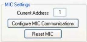
Current Address
This box indicates the address to which commands are sent from Camset. This therefore needs to match the address of the MIC that needs to be controlled.
When the MIC is booted the first line of the messages it sends is the address, which is read and put into this box automatically.
Configure MIC Communications
This button opens up a new window which provides the options to reconfigure the MIC communications settings. These options will depend on the MIC model connected.

In order for any of these modifications to work, Camset must have full communications with the MIC. Ensure this by performing a simple manual control test (Up, Down, etc). To store the new settings press Apply once the modifications have been made or alternatively press Cancel to discard any changes.
New Address
This input box defines the new address the MIC should change to once Apply has been clicked. The value will also be copied over into Current Address on the main form to provide continual control.
New Protocol
The drop down list here provides a full list of the protocols available in Camset. Control depends upon selecting the correct protocol in the drop down list to match the protocol that is loaded onto the MIC400; if the incorrect protocol is selected in Camset the MIC may not respond. To regain control should this happen, reset the Camset Protocol back to what the MIC originally was.
MIC440 Explosion Protected CCTV Camera System| Installation and Operation Manual
EN | 25
New Baud Rate
This drop down list will provide the valid baud rates for the chosen protocol. The baud rate options reflect the protocol as set on the main form for Camset itself. In FV protocol the option is a toggle which simply switches the MIC between 4800 and 9600. If control is not present after the window is closed, try changing the Camset Baud Rate.
Reset MIC
This sends out a command to reboot the software. This is not a hardware reboot; the only way to do that is to remove the power supply to the MIC.
Camset Settings
The Camset Settings section as shown above control the Protocol, MIC model, Baud Rate and Comm Port used; select the appropriate parameters for your MIC440 from the dropdown menus.
Some functions in Universal Camset may not be supported by particular protocols; any incompatible functions will be greyed out if it is not supported in a given protocol.
The communication settings will be set to the default for the chosen protocol, indicating this on the Camset Baud Rate drop down list.
Reset Camset
This re-initialises all of the controls for the software to the state it would be on boot.
MIC Model
This provides a list of all the available MIC Models. This should be set to the type of camera being controlled as Camset is then set up accordingly to provide more or less options dependant upon the combination of this setting with the Camset Protocol above.
Comm Port
This provides a list of the available Comm Ports detected by the software on the PC. If a comm port is in use when it is selected the user will be prompted with an error, and should either select another port or close the application currently using it. If the MIC-USB485CTR, USB to RS485 convertor is being used, when plugged in this will show on the Comm Port drop down menu as USB, simply select to use. The final option is close which will close any open communications port meaning that other applications can then use the port for other purposes.
Camset Baud Rate
This displays the current Baud Rate at which outgoing messages are sent, and the other options available for the given protocol above. Changing this without first changing the MIC baud rate will cause a loss of communications.
RTS
This defines the state of the RTS line on the serial port which can be used power in line RS232 to 485 adapters.
Comms Mode
There are 3 available options for comms modes:
Full Duplex: Full 2 way 4 wire communications connection. Messages are transmitted and received on separate comms pairs.
Half Duplex: 2 way, 2 wire communications connection. Messages are transmitted and received on the same pair of wires. The 485 drivers deal with the switching of the line directions automatically.
Simplex: 1 way 2 wire communications connection. Messages are only transmitted to the camera. This will work for most manual controls, but anything that requires a response, such as Pot Test, Exact Positioning, Programming etc will fail.
Manual Control
Pan, Tilt and Zoom Controls
The Up, Down, Left and Right buttons send commands to the MIC to move in the selected direction at the speed indicated by the Speed Slider.
Zoom In and Zoom Out control the zoom position of the camera lens at a fixed rate.
Latch PTZ: This tickbox will Latch the PTZ controls for continuous tilt or rotation as required.
Iris Controls
Auto Iris lets the MIC automatically adjust to changing light levels, where Manual
Iris gives the user control with Open and Close buttons.
Focus Controls
Auto Focus lets the MIC automatically focus on a changing scene, Manual Focus
gives the user control with Near and Far buttons.
Auxiliaries

Slow Zoom: Reduces the speed at which the MIC zooms.
PTZ Scale: Scales the MIC speed dependant on zoom position.
Wiper: Turns on or off the MIC wiper if fitted.
Washer: Activates the washer relay on the MIC-WKT card or the MIC-ALM card if fitted in the PSU. This also moves the MIC to the stored WashWipe position and turns on the wiper. Once de-activated, the MIC will return to its original position and turn off the wiper.
IR / Thermal: Depending on the MIC, this will do one of three things. For a non-IR standard MIC, the IR cut filter will come in and the image will go black and white. For a twin IR MIC, the cut filter will come in and the lamps will turn on. Note: If the lamps do not turn on, ensure the power supply is an IR version and that Auto Alarm and Multi Alarms in the MIC Setup tab are both turned on.
For a MIC412, the video output will switch from the Sony module to the thermal module; the controls on the Thermal tab will also now function.
Digital Zoom: This will enable the MIC to continue into the digital zoom once the optical limit has been reached. This also needs to have Digital Zoom Enabled under the MIC Setup tab.
On Screen Data: This activates the Sony module's on-screen icons.
Preset Positions

Preset positions are locations stored by the MIC in Pan, Tilt, Zoom, Focus, etc., which can be either called back manually, or returned to as part of a preset position tour.
To learn a position, move the MIC to the desired location and then either enter the preset number in the box available or press the Preset Number button until it displays the desired value. Then press the Learn button to store. Once stored, the value in the input box will be cleared.
Returning to a position uses the same number entry method and then press the Go To instead.
The Learn All Presets button will set every preset position available for the given protocol to the current position. This may take a few seconds.
Tour Controls

Tours provide a way of making a MIC continually move to points of interest within its visible range. There are two different methods to enable this: Preset Tours recall preset positions in the set order, waiting at each for a desired dwell time, while Pattern Tours mimic the operator's movements whilst recording so it can follow a defined path.
Access to these methods is entirely protocol specific, meaning if it is shaded out, the feature is not supported. In some cases there are up to 6 tours available.
Preset Tours
To save a preset tour, simply enter the end preset number into the input box and a corresponding dwell time and press Program Tour. This initiates a simple tour with each step's preset position being fixed and the dwell time constant across the tour, stored to the Tour Number. More comprehensive program methods are normally available through the control system.
The Tour Number selects the tour to which you save and also play from. The Start Tour button initiates the current programmed sequence for the given Tour Number.
Pattern Tours
Depending on the protocol, the controls for these vary. Some fully implement the recording functionality and in these cases the Start Recording and Stop Recording buttons are used, with user manual control in between. This is again stored to the Tour Number as set.
Other protocols use an add point method, where Start Recording and Stop Recording are used in the same way, but instead of manual control in the middle Add Tour Point is used to insert a preset position with the options specified Preset, Dwell and Speed.
Soft Stops and Non Dwell Zones
This feature offers a method of restricting the MIC's movements to a certain area. A "box" is defined using the Top Left and Bottom Right buttons which provides the area within which the MIC is allowed to move. To clear the area set both corners to the same location.
Non-Dwell Zone
This provides the opposite of Soft Stops, in that an area can be defined within which the MIC cannot stop. The area is defined and cleared in the same way using the Top Left and Bottom Right buttons. Once the MIC enters the area it passes straight through to the opposite edge.
Clear
This button clears both the Soft Stops and the Non-Dwell Zone, which is required after a MIC has its protocol re-flashed (see Programming section).

MIC Setups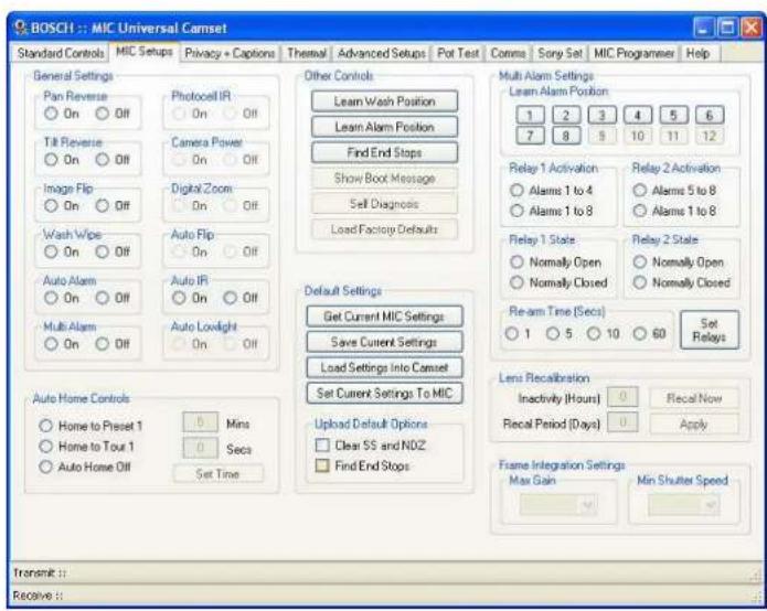
The MIC Setups tab contains the basic camera controls such as General Settings, Multi alarms (if MIC-ALM card is fitted), Relays, AutoHome options and the Default Settings.
General Settings
Pan Reverse
This will invert the pan rotation of the MIC compared to the commands from the controller. This would be used if a MIC was inverted to regain logical control.
Tilt Reverse
This will invert the tilt rotation of the MIC compared to the commands from the controller.
Image Flip
This manually inverts the image from the camera module, which may be used on an inverted camera where the head cannot be rotated through 180 degrees. Inverting the image would normally also require some modification of the control directions.
Wash Wipe
If Wash Wipe is On then, when the Wash auxiliary is set the MIC will return to a preset Wash Position activate the washer relay in the PSU and turn on the wiper. When the auxiliary is turned off again, the MIC will return to its prior position and turn the wiper off. If Wash Wipe is Off then when the aux is activated the MIC will simply close the washer relay and remain in its current position.
Auto Alarm
This is used for both single and multi alarm functionality. With Auto Alarm on and Multi Alarm off, the MIC will monitor the tamper switch line, moving to the programmable Alarm Position when the connection is grounded. If Auto Alarm is turned off the MIC will ignore any change in status of the tamper line.
Multi Alarm
With this the user can setup a separate position for each of the 8 alarm inputs. Any given alarm input will trigger the MIC to move to the position with which it is associated. To get this functionality working both Auto Alarm and Multi Alarm should be turned on.
Photocell IR
This mode enables the user to attach an external photocell to the power supply to control the IR lamps. The device is connected to alarm input 4, meaning that when the light levels drop sufficiently alarm 4 is triggered, and instead of moving the MIC detects this as an activation signal for the lamps. When the light levels pick up again, the alarm will deactivate and the lamps will be turned off. This mode can enable the user to hide the sensor away from any large external lighting which may cause the camera to flick in and out of IR mode under Auto conditions.
Camera Power
This can be used to turn the camera module inside the MIC off as required.
Digital Zoom
This is an override for the Digital Zoom Auxiliary, meaning that if On this will allow digital zoom to be controlled by the aux state, but if off, will never allow digital zoom no matter what the state of the aux.
Auto Flip
With this enabled the MIC will pan through 180 degrees as it reaches the vertical position so the user can then tilt down the other side meaning the MIC video is never inverted. Once the rotation is complete the controls are reversed until a stop command is received, at which point they are returned to normal.
Auto IR
In this mode the camera module is monitored for its current IR state, as soon as the light drops sufficiently, the module will automatically put the cut filter in place and switch to black and white, at which point the MIC will turn on the IR lamps.
Auto Lowlight
If this is turned on, the MIC will decrease its shutter speed as the light levels drop, rather than increasing the gain. Motion blur on the video can occur if the frame rate drops sufficiently low, which may not be ideal for a camera which is continually moving. However if motionless, the images will not have the grain associated with lowlight conditions. The gain at which a change is made and the lowest frame rate can be controlled under the Frame Integration section.
Auto Home Controls
Auto Home Controls
Home to Preset 1 Home to Tour 1 ○ Auto Home Off

Mins

Secs
Set Time
After a programmable time with no manual control, the MIC can be configured to either move to the home position (Preset 1) or start tour / pattern 1. With Auto Home turned off, the MIC will simply remain stationary until the next user input. The amount of time before this takes place can be set using the input boxes and the Set Time button.
MIC440 Explosion Protected CCTV Camera System Installation and Operation Manual
EN | 31
Other controls
Other Controls

Learn Wash Position
This is the position that the MIC will return to when the Washer Auxiliary is activated and Wash Wipe is turned on. This should point towards the washer jet nozzle.
Learn Alarm Position
This is the alarm position for the tamper switch. The MIC will return to this position if Auto Alarm is turned on, Multi Alarm is turned off, and the tamper line in the PSU is pulled to ground.
Find End Stops
This will get the MIC to rotate in the tilt axis first down then up to its mechanical limit stops. It will then store a "soft" limit a few units back from these for normal use. During this process manual control is not available.
Show Boot Message
This will display the boot message that appears on the video for a few seconds. This may be helpful to determine the current software of the MIC without having to do a full reboot.
Self Diagnosis
This function is for future products and does not work with the MIC400 or MIC412.
Default Settings

The Default Settings tab reads and sets settings from the following sections:
- Manual Control Auxiliaries
- General Settings
- Auto Home Controls
- Multi Alarm Settings
- Lens Recalibration
- Frame Integration Settings
- All Thermal controls
All other settings will not be saved, loaded, downloaded, or set through the following controls.
Get Current MIC Settings
This downloads the current status of each of the settings from the MIC and loads it into the text boxes and radio buttons on Camset. This provides an easy way of viewing the current setup of each MIC and also a way of copying the settings from one into the next.
MIC440 Explosion Protected CCTV Camera System Installation and Operation Manual
EN | 32
Save Current MIC Settings
This option will first prompt for a file location and then store the current state of all the options outlined above to an XML file which can then be loaded at a later date back into Camset as a standard for a specific site.
Load Settings into Camset
This will prompt to open an XML file as saved above. Only valid Camset Default XML files will work.
Set Current Settings to MIC
This will go through each of the settings above except for thermal, and send out the commands to the MIC to set it up as Camset displays. This may take a few seconds as there are several commands involved in this process.
Upload Default Options
At the end of this there are 2 extra options for defaults, Clear SS and NDZ will clear any saved Soft Stops and Non-Dwell Zones and then Find End Stops. These options may be used to completely set up a MIC after it has been reprogrammed to a new protocol.
Multi Alarm Settings
Multi Alarm Settings
Learn Alarm Position

Learn Alarm Positions
Simply point the MIC400 at the position you would like it to cover when each numbered alarm is triggered and press Learn Alarm Position to set this.
Relay 1 Activation
○ Alarms 1 to 4
○ Alarms 1 to 8
Relay 2 Activation
○ Alarms 5 to 8
○ Alarms 1 to 8
Relay 1 State
○ Normally Open
○ Normally Closed
Relay 2 State
○ Normally Open
○ Normally Closed
Re-arm Time (Secs)

Set Relays
Relay State, Activation and Re-arm
This function is available only to MIC cameras with the MIC-ALM card fitted into the MIC PSU or the MIC400IR Power Supply which has Four (4) Alarm Inputs built in.
The MIC-ALM multi alarm card provides 2 output relays which can be configured to close or open on given alarm Inputs. Relay 1 can be activated from either alarm inputs 1 to 4 or 1 to 8 and relay 2 with alarm inputs 5 to 8 or 1 to 8.
The re-arm time is a time in seconds before the MIC returns to its current position and returns the relay to its prior state. The options for this are 1, 5, 10 or 60 seconds. To send the settings to the MIC select the desired options and then press Set Relays.
Lens Recalibration and Frame Integration

This section defines when and how often the Sony Optical Camera block should perform a recalibration process. The first field inactivity defines how long in hours it should be after the last manual control command before the first recalibration should take place, and the second is a time in days between each successive recalibration from then on.
To set these enter the appropriate values in the text boxes provided and press Apply. Alternatively the Recall Now button will perform a manual recalibration.
Frame Integration Settings
This section defines the Max Gain and Min Shutter Speed parameters used by the MIC when in Auto Lowlight mode. The drop down lists provides the actual settings available in dB for gain and FPS for shutter speed. The On Screen Data auxiliary command will indicate the current frame rate if required. The values are set by simply selecting the desired option from the drop down lists.
Privacy and Captions
Due to space limitations within the MIC440 camera a privacy card cannot be fitted hence the privacy function does not function, captions are unaffected.

The Privacy and Captions tab allows the user to define and set the privacy mask function if the optional privacy card is fitted; this is not applicable to the MIC400 as the privacy card cannot be used with the thermal imager.
Privacy Controls
For MIC400 Cameras with the optional privacy card fitted (Not MIC412 or MIC440)
Masks On / Off
This is an override setting to turn masks completely On or Off. This will not clear each individual mask's settings, so when Off is sent they will disappear and then re-appear with On, in the same positions.
Crosshair On / Off
This setting makes a crosshair appear on the video display centered on the middle of the video. This can then be used to set individual mask pixels with the appropriate command from below.
Show / Clear Mask Style
This setting provides a preview of the current mask style. This will only work if the Crosshair is turned On. It will show a small privacy block to the right of the crosshair center. If nothing appears, the mask may be clear, so use the Set Mask Style to change to a visible setting. Once the required style has been selected; press Clear Mask Style and Crosshair Off, to return to the normal state.
Mask / Clear Whole Screen
These functions will add or remove a privacy mask the size of the entire current view. Moving the MIC in Pan or Tilt should then indicate the zone clearly. This would most commonly be used in conjunction with zoom where a window can be made full frame and then the whole thing masked as opposed to the method below which may take significantly longer.
Mask / Clear Pixel
This is a more accurate way of creating privacy masks one pixel at a time. The Pixel is created at the center of the image, or where the crosshair points if it is visible.
Set Crosshair
This will create a pixel sized mask as with the function above, and will also bring up the crosshair. Press again to remove the crosshair or use Crosshair Off.
Set Mask Type
If Crosshair and Mask Style are both turned On, this function can be used to step through each of the available mask types one at a time. This will not update all the masks to the same type, only the ones that are created subsequent to the change.
Load Factory Defaults
Clears the current Privacy masks and resets the privacy card to the factory defaults.
MIC Configuration
These options define the MIC's orientation, which defines how the masks track. For inverted MICs, the head would normally be rolled around through 180 degrees, with Pan Reverse On to regain sensible control. However, with inverted IR MICs, the head cannot be rotated around due to the IR Lamp arms, and therefore the video must be inverted, and both controls reversed.
Basic Calibration
This sends a set of default commands to the MIC to initialize the privacy for an upright MIC. This will not be perfect as each board needs fine individual calibration but provides a good starting point.
Zoom Alignment
The zoom alignment buttons provide accurate calibration of the mask tracking. This would normally be carried out by using a vertical line of mask on along a known straight edge. If this line then moves as the MIC pans and tilts, it can be corrected using the appropriate arrow. The labels indicate the current value in both the Vertical and Horizontal planes, which will be incremented or decremented dependant upon the direction pressed.
Direct Command
All privacy commands consist of 2 Hex bytes, a command byte and a data byte. These perform all of the privacy functions available. To enter commands, enter the 2 bytes in Hex, into the boxes provided and press Send Command. Entering random commands here may result in very odd results so please do not use unless under specific instruction.
Save Current Settings
Once any calibration changes are made, this button should be pressed to save the new values permanently.
Privacy Calibration
Disabled for cameras without a privacy card fitted

CAUTION: The privacy calibration settings should be configured at manufacture and should therefore not need to be changed on site. Any changes to these settings may be difficult to correct, so please do not attempt to change anything unless under instruction from Bosch.
The Privacy Calibration section deals with the calibration settings of the privacy masking. i.e. how the masks track as the MIC is moved in Pan, Tilt or Zoom.
MIC Configuration
These options define the MIC's orientation, which defines how the masks track. For Inverted MICs, the head would normally be rolled around through 180 degrees, with Pan Reverse On to regain sensible control. However, with inverted IR MICs, the head cannot be rotated around due to the IR Lamp arms and therefore the video must be inverted and both controls reversed.
Basic Calibration
This sends a set of default commands to the MIC to initialise the privacy for an upright MIC. This will not be perfect as each board needs fine individual calibration but provides a good starting point.
Zoom Alignment
The zoom alignment buttons provide accurate calibration of the mask tracking. This would normally be carried out by using a vertical line of mask on along a known straight edge. If this line then moves as the MIC pans and tilts, it can be corrected using the appropriate arrow. The labels indicate the current value in both the Vertical and Horizontal planes, which will be incremented or decremented dependant upon the direction pressed.
Direct Command
All privacy commands consist of 2 Hex bytes, a command byte and a data byte. These perform all of the privacy functions available. To enter a command, enter the 2 bytes, in Hex, into the boxes provided and press Send Command. Entering
random commands here may result in very odd results so please do not use unless under specific instruction.
Save Current Settings
Once any calibration changes are made, this button should be pressed to save the new values permanently.
Captions
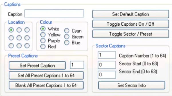
The Captions tab allows the user to set up captions, Sector or Preset Captions; Screen Location and Caption Colour are all user definable.
The MIC has 3 different caption options available. On the MIC 400 model range only one line of text is available and therefore a Preset Caption will overwrite a Default Caption.
The Default Caption can be treated as the name of the camera. It will appear on the video whenever it can, i.e. when no Preset or Sector captions are selected.
Preset Captions can be used to display a different title for each of the preset positions available. This will be loaded once the MIC has reached the position.
As an alternative, the same 64 captions can be used, not for preset positions but for rotational sectors. The MIC's pan is split into 64 segments and a different caption can be assigned to each or to a group. Using this option can result in an occasional slight control lag.
Whatever caption is being set the writing must be entered into the Caption Text Box. The caption will be displayed in block capitals and only certain extra characters are recognised. Unknown characters will be displayed as "?".
Location and Colour
These options define where on the video and in what colour the caption will be.
Set Default Caption
This programs the current caption (if valid), position and colour settings to the default caption. If captions are turned on this should appear immediately on the video.
Toggle Captions On / Off
This setting is a global On / Off setting for captions. If Off then no captions will be displayed, Default, Preset or Sector.
Toggle Sector / Preset
This toggles between the 2 caption modes of Preset or Sector. These options are mutually exclusive.
Preset Captions
This section provides 3 options, to either set one preset caption to the preset number specified in the input box. Set all 64 presets to the same caption, or clear all 64 preset captions to nothing.
Sector Captions
This section allows the definition of the sectors and what caption to use for each. First the Caption Number is entered which corresponds to a preset caption, then the start and end of the group in terms of an individual sector. Press Set Sector Info to store the data.
Thermal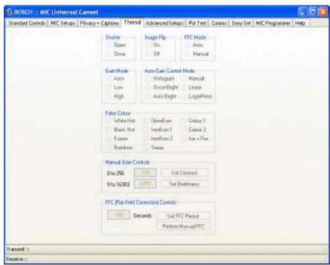
The Thermal tab controls the function of the FLIR thermal imager in the MIC412 only; this screen has no function with a MIC440 Camera.
Advanced Settings

The Advanced Settings tab offers engineering and special auxiliary control modes for Pelco and Panasonic protocols (see Help file for details).
The MIC stores various statistics about itself, including temperature and humidity, and various timers for different parameters, which may be of interest to the end user, but are mainly implemented as an engineering tool.
Temperature and Humidity
This will only work if the MIC400 has the appropriate control card with the temperature and humidity sensor attached. Current, Max and Min are displayed for
both in degrees and a percentage respectively. If the MIC reaches 70% humidity inside the head a small "H" is displayed in the top left corner indicating a Humidity problem. If this appears, make contact with Bosch Security Systems.
Timers
The timers monitor most of the common functionalities of a MIC: Panning, Tilting, On Tour, Since Built, Stationary, Wiping and IR Lamp shown in Weeks, Days, Hours, Minutes and Seconds.
Clear All Statistics
This function will set Max and Min for temperature and humidity to the current reading, and will clear all of the timers to "0". This feature should only be used when a MIC is first built or repaired, and therefore is locked out with the Advanced Controls Password.
MIC Serial Number
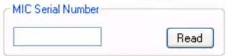
This feature is used to set or read the actual MIC Serial Number. This may be required to reprogram the MIC through the telemetry. The Set function is locked out with the Advanced Password as this should only be performed at the manufacturing stage, however read is available to use as required.
MIC440 Explosion Protected CCTV Camera System Installation and Operation Manual
EN | 38
EEPROM Copier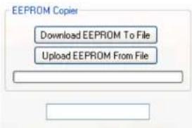
This feature can be used to download the complete EEPROM block from the MIC to a file and then upload it to another. This will port across every single setting stored in the MIC, thus making a mirror copy when loaded into the next. Everything except for the privacy calibration will be transferred as this is stored separately on the privacy card itself. Before using this feature ensure you are aware of the consequences, in that all preset positions will be changed to the ones stored in the file, same with the Sonyset table and finally the MIC address will also be copied.
Once uploaded, Camset will prompt to reboot the MIC which will then load the new settings into the MIC.
If any errors occur in the download or upload process then do not attempt to upload a half complete file, retry the process until it works fine.
Download EEPROM To File
This will prompt for a file location of type ".epm". If valid then the process will begin with the current status indicated on the progress bar. The file stores each data byte and its address in memory. These files should not be edited under any circumstances.
Upload EEPROM From File
This will prompt for a ".epm" file to open, again if valid the process will begin and the progress bar will show the current progress.
Remap Auxiliary (Pelco Only)
This section provides the option, for MIC400s with Pelco protocol only, to modify what aux the MIC actions for a given aux number input.
Pelco has 8 aux commands available and the MIC functions that can be mapped to them are as follows:
- Auto Focus
- Digital Zoom
- Auto Exposure
- IR
- Wiper
- Washer
- OSD
- Backlight
To modify an aux mapping, simply select the desired function and aux number from the list boxes and press Set. The default button will assign the functions in the order as above to aux's 1 through 8.
Menu Controls (Panasonic Only)![graph TD A["Menu On / Off"] --> B["Menu Position Up"] B --> C["Menu Position Down"] C --> D["Menu Value Up"] D --> E["Menu Value Down"]](/content/2026/06/1364137/images/3d40ae78a116a6217b23ac3ebfd47b96dd406b17378aa64f0f7d1020547d407e.jpg)
Matrix Controls
The options here provide controls for a Forward Vision Matrix. The Enable and Disable Alarm buttons will take the number provided in the upper input box, and perform the specified function on that alarm input.
The Watch button can be used to change the input channel on a Matrix (1 to 16) to the value specified in the lower input box.
POT Test
The POT Test tab is used as an engineering tool to determine the MIC's position, Motor PWM, Motor Speed in both Pan and Tilt, and the PSU level inside the MIC.
All the results are plotted onto a continually updating graph on the page and the current results shown in numeric values below. This process requires a reliable 2 way communications link with the MIC.
Manual and Preset / Goto Controls
These work as per the controls on the Standard Controls page although instead of stopping when released the MIC will continually move until a separate stop command is sent. The numeric key pad controls also work whilst in pot test although the learn preset method using the number keys does not.
MIC440 Explosion Protected CCTV Camera System Installation and Operation Manual
EN | 40
Pot Test Controls

Start
This initiates the Pot Test process. Continual commands will be sent requesting the MIC's current data, the responses will be decoded and data printed and plotted on the display.
Stop
This stops the process running. Pot Test is also stopped when another tab is selected to ensure communications aren't held up when trying to perform an operation from another page.
Clear Trace
This will clear the graph plotted and reset the cursor to the left hand side of the picture box.
Reset Measurements
Whilst Pot Test monitors the current values, it also measures the maximum, minimum and average readings for PWM in both the pan and tilt axis. These are displayed below the current readings in Pan Readings and Tilt Readings respectively. This button enables the user to reset these calculated values.
Save Plot
This control enables the graph plot to be saved as a .jpg image to a location determined on the save dialog box that opens.
Rotation Analyser
This sub window can be used to accurately measure the PWM of either axis of the MIC, plotting the data against position rather than reading, which provides a easy to read way of locating tight or loose spots in the tested axis. The results can then be saved as a Word .doc report and automatically printed to the default printer, whilst also giving the option to simply view the results on the window. The user can then use the mouse on the plot to drive the MIC back to suspect positions for further analysis. This functionality is only available in FV protocol, and works best with a baud rate of 9600. To exit the sub window press Close.
Visible Traces
This section enables the switching on and off of the various traces available from the Pot Test plot. By default current Pan and Tilt position and PWM is displayed, and the following can be added, which are all real time calculations made since Reset Measurements was last pressed:
• Min Pan PWM - Maroon - Max Pan PWM - Red • Average Pan PWM - Orange - Min Tilt PWM - Maroon - Max Tilt PWM - Red • Average Tilt PWM - Orange
As these are displayed in the same colours, it is recommended that only one set of Max, Min, Average be displayed at any one time.

Pot Test Results
| Pan Readings | |
| Pos | 0 |
| PWM | 0 |
| Speed | 0 |
| Min | 0 |
| Max | 0 |
| Average | 0 |
Pan / Tilt Pos
These indicate the current position in Pan and Tilt in Red and Blue respectively, over the range of 4096 units for 360 degrees rotation.
Pan / Tilt PWM
These indicate the current PWM (Pulse Width Modulation) of the motor, with Pan and Tilt being indicated in Green and Purple respectively. This gives an indication of how hard the motors are working.
Pan / Tilt Speed
These results are the actual speed that the MIC is moving in either axis. The results are not plotted on the graph only shown in the respective window.
PSU Level
This reading shows the Voltage level of the main power rail in the MIC. There are 2 scaling options for different control cards, as a guide 6E came into production around mid 2007, so anything after this would use this option.
Mouse Point Values
This area indicates the scaled values corresponding to each of the 4 axis with respect to the current mouse position. This can be used to easily determine peak or trough values at any point on the trace.
Pot Test Plot Area
Plot Area Controls
The plot area can be zoomed in and out using the scroll wheel on the mouse, and then reset to default by pressing Right Mouse Click - Undo All Zoom/Pan. The plot can also be panned using the scroll bar to the lower of the plot area. By pressing Right Mouse Click - Show Point Values, the value of the point closest to the mouse pointer will be indicated as an X,Y coordinate in a box next to the pointer.
Comms
The Comms tab enables the user to monitor the communications to and from a MIC or any other serial device connected to the open comm port. This requires 2 way comms for any of the associated options.
Log Communications
This check box enables or disables the capture of incoming and outgoing data to the text display. With the Communications Grabber running, the comms to and from the MIC will be slightly slowed down, which may be very noticeable on features such as Pot Test, so unless specifically required, it would be advised that this is turned off.
MIC440 Explosion Protected CCTV Camera System Installation and Operation Manual
EN | 42
Capture in ASCII
This changes the way in which the data is displayed. If not checked, then the data is displayed in comma-separated Hex bytes (e.g., 54, 45, 53, 54). If it is checked, then each byte is converted into its corresponding ASCII character (e.g., TEST). However, this only works if the protocol sends out valid ASCII bytes; all other values, less than 32 and over 127, will result in a "?" being printed.
Assume New Message after 50mS
This is a way of separating out consecutive commands and individually time-stamping them. If there is a 50mS gap between transmitted or received bytes, then the next byte is taken as a new message.
Time Stamp Data
If checked, then each new packet will be titled with the date and time of transmission or reception; otherwise, the data will just be indicated with a Transmit or Receive tag.
Clear Comms
This simply clears the current communications window.
Save Data to File
This will prompt the user for a file location where the comms can be saved. They will be output as a ".doc" file formatted in the same way as displayed in the window, which can be opened in Microsoft Word.
Send Direct Command

This feature enables the user to specify an exact command in Hex bytes to send to the MIC. The long input box is used to enter the command in individual comma-separated Hex bytes, without the header or CS.
For example, a complete Learn Preset 1 command in FV protocol is: 0A 30 31 30 41 36 4D 30 31 80
The header on this is: 0A 30 31 30 41 36
and the checksum: 80
So to transmit the same command, the input box should read: 4D, 30, 31
Any variation on this will cause an error to be flagged indicating why the command is wrong. Once written, the command is sent using the Send Now command.
Communications Testing

Communications Testing enables the user to test the quality of the communications link to the MIC. This does require 2-way comms for any of the below options. Use the Cancel button at any time to stop the testing process.
MIC Comms
To initiate, select the MIC Comms radio button and press Test. This will repeatedly query the MIC for a set response the number of times of which is defined by the Test Repetitions input box. If the response is valid and within the correct time frame, then it is logged as a pass. No response or a late response is flagged as a time out, and short or incorrect data is classed as a fail. The results of this are continually displayed in the small window directly below the Test button. Any faults along the length of the comms lines will normally result in fails or timeouts depending on the severity of the problem.
Cam Comms
Starting this is as with MIC Comms but by selecting the Sony Cam Comms radio instead. So long as the MIC Comms are 100% reliable, this will return the reliability of the comms to the Sony Module inside the MIC, again returning passes, fails, and time outs in the same frame. If these are intermittent, please contact Bosch Security Systems for advice.
Alarms
This test monitors the state of the 8 alarm inputs if applicable, printing if they are turned On or Off continually throughout the test in the larger of the 2 results windows. The test is started by selecting Alarms from the options and pressing Test.
Detect All MICs
This sends out a request to each MIC address for its Software Version printing the Response and the respective address in the large results box. This can be used in conjunction with setting a site of multiple MICs all to address 0 (random address) to then find what address each is on and therefore regain control.
Sony Set
For FV Protocol Only
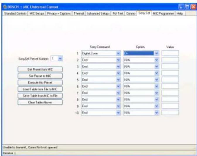
The Sonyset tab shows the controls required for Creating, Loading, Saving, Uploading and Downloading SonySet tables in FV protocol only.
A MIC can store 10 Sony Set tables, each containing 10 separate camera controls.
This means that a complete setup for the camera module (shutter speed, gain level, effect etc) can be saved and loaded back at any time through an input from the user. These can therefore be used to define certain camera states for different positions or requirements of an installation, for example, one could be set up for normal running auto everything, and another set-up for ANPR, with a specified
frame rate and gain etc. normal running auto everything, and another set-up for ANPR, with a specified frame rate and gain etc.
These states could then be toggled by calling them up with an Execute SonySet command.
SonySet Controls
SonySet Preset Number

Get Preset from MIC
Set Preset to MIC
Execute this Preset
Load Table from File to MIC
Save Table from MIC to File
Clear Table Above
SonySet Preset Number
This is where the SonySet Preset number is selected, there are 10 options available relating to 10 complete camera setups.
Get Preset from MIC
This process will query the MIC for the table number as specified in the SonySet Preset Number list. Each valid command and value will be shown in the table. If any data is incorrect or the command does not exist the Sony Command column will display "Invalid". It is not advised to reprogram a MIC with any "Invalid" commands.
Send Preset to MIC
This will read through the entire table checking for valid commands and respective values indicating any discrepancies, and then form the commands to send the data to the MIC. The data is stored to the preset number as indicated in the SonySet Preset Number in list.
Execute this Preset
This will send a command to the MIC to read the commands from the preset number in SonySet Preset Number list in memory and send them on to the Sony module. This will only send commands stored not the ones in Camset, so to test a Setup first use Send Preset to MIC then Execute this Preset.
Load Table from File to MIC
It is also possible to Load a complete table of all 10 presets directly into the MIC from a file. This will prompt the user to open an XML file containing all of the information required. The information will not be displayed in the table display, it will simply be sent straight to the MIC.
Save Table from MIC to File
This creates the files that can be used by the feature above. First it will prompt for a file location to store and if valid, poll the MIC for each command of each preset and store all of the information to an XML file.
Using the Save and Load file functions as above means it is possible to copy a complete SonySet table from one MIC to another to easily setup a site with the same configuration.
Clear Table
This clears the table in Camset and will not do anything to the data stored at the location in memory in the MIC itself. To clear a MIC table, use this function and then Send Preset to MIC.
The SonySet Table
| Sony Command | Option | Value | |
| 1 | Digital Zoom | On | |
| 2 | End | N/A | |
| 3 | End | N/A | |
| 4 | End | N/A | |
| 5 | End | N/A | |
| 6 | End | N/A | |
| 7 | End | N/A | |
| 8 | End | N/A | |
| 9 | End | N/A | |
| 10 | End | N/A |
The table on the right of the form indicates the current state of one of the presets. The first column Sony Command indicates the command type for each of the 10 steps in each preset. The Option column indicates the current value for the chosen command, (e.g On or Off) or if the command is a direct set type, this will indicate the range available and the result is displayed in column 3, Value.
A full list of available commands and values is shown below.
Changing any of the Sony Commands will invoke the corresponding Option to also change and take on the top value in the list of available options, therefore clearing the previous setting from memory. If the command type requires a numeric input, the corresponding Value box will indicate the lower bound of the range, which can then be changed to any valid value.
If only a few commands are utilised on the list then the rest should be set to "End" which will display "N/A" in the option column.
Below is a list of the available SonySet Commands and their corresponding Values or valid value ranges:
Table M - Sonyset Commands
| Command Value | |
| Camera Power On/Off | |
| Zoom Set 0 to 28672 | |
| Digital Zoom On/Off | |
| Focus Set 4096 to 49152 | |
| Focus Mode Auto/Manual | |
| Focus Control One Push Trigger / Force Infinity | |
| AF Sensitivity High/Low | |
| Focus Near Limit 4096 to 49152 | |
| White Balance Mode | Auto / Indoor / Outdoor / One Push / Auto Tracing / Manual |
| White Balance Control One Push Trigger | |
| Red Gain Control Reset / Plus 1 / Minus 1 | |
| Red Gain Set | 0 to 255 |
| Blue Gain Control | Reset / Plus 1 / Minus 1 |
| Blue Gain Set | 0 to 255 |
| Exposure Mode | Auto / Manual / Shutter Priority / Iris Priority / Gain Priority / Bright / Shutter Auto / Iris Auto / Gain Auto |
| Slow Shutter Mode | Auto / Manual |
| Shutter Control | Reset / Plus 1 / Minus 1 |
| Shutter Set | 0 to 19 |
| Iris Control | Reset / Plus 1 / Minus 1 |
| Iris Set | 0 to 19 |
| Gain Control Reset / Plus 1 / Minus 1 | |
| Gain Set 0 to 19 | |
| Bright Control Reset / Plus 1 / Minus 1 | |
| Bright Set 0 to 19 | |
| Exposure Comp Control | Reset / Plus 1 / Minus 1 |
| Exposure Comp Set 0 to 14 | |
| Exposure Comp Mode On / Off | |
| Backlight On / Off | |
| Aperature Control Reset / Plus 1 / Minus 1 | |
| Aperature Set 0 to 19 | |
| Low Lux On / Off | |
| Hi Resolution On / Off | |
| Image Flip Horiz | On / Off |
| Freeze Frame | Off / Negative / Black & White |
| On Screen Data | On / Off |
| Caption Display | On / Off |
| Auto IR | On / Off |
| Camera Initialise | Lens Recal / Bad Pixel Correction |
| Image Flip | On / Off |
| End | N/A |
| Invalid | N/A |
MIC Programmer
Due to the control card fitted into the MIC440, telemetry programming is not supported. Please contact Bosch Security Systems if you require a change of software protocol on your MIC440.
CHAPTER 5 Technical Specifications
CAMERA MODULE
Image sensor 1/4" EXview CCD
Picture elements 380K NTSC / 440K PAL (WIDE)
Horizontal resolution 470TVL NTSC / 460TVL PAL (WIDE)
Filter Automatic mechanical IR cut filter
Focus system Auto or manual
Iris Auto or manual with slow shutter integration modes
Synchronisation Internal / External (V-Lock)
Recommended illumination 100 to 100,000 lx
Signal/Noise ratio 50dB or more
Back Light Compensation (BLC) On/Off
White balance Automatic
Automatic Gain Control (AGC) -3 to -28 dB, 2dB steps
Aperture control 16 steps
18x optical zoom module
Lens F=4.1mm (WIDE) to 73.8mm (TELE), F1.4 to F3.0
Zoom 18x optical (12x digital)
Angle of view 48° (WIDE end) to 2.8° (TELE end)
Minimum illumination 0.7 lux (F1.4, 1/60s NTSC, 1/50s PAL), 0.11 lux
(F1.4, 1/4s NTSC, 1/3s PAL), 0.01 lux or less
(F1.4, 1/4s NTSC, 1/3s PAL, ICR ON)
Shutter speed 1/1 to 1/10,000s (22 steps) NTSC, PAL
36x optical zoom module
Lens F=3.4mm (WIDE) to 122.4mm (TELE), F1.6 to F4.5
Zoom 36x optical (12x digital)
Angle of view 57.8° (WIDE end) to 1.7° (TELE end)
Minimum illumination 1.4 lux (1/60s NTSC, 1/50s PAL), 0.1 lux (1/4s
NTSC, 1/3s PAL), 0.01 lux or less (1/4s NTSC,
1/3s PAL, ICR ON)
Shutter speed 1/4 to 1/10,000s (20 steps) NTSC, 1/3 to
1/10,000s (20 steps) PAL
OPERATIONAL*
Auto flip Yes
Manual flip Yes
Presets 64 telemetry presets accurate to less than 0.1°
utilising resolver technology (using FV protocol,
10 camera set-up presets to allow ANPR, colour
correction etc.)
Preset tours 6 tours each with up to 32 points
Sector titles Yes (64 sectors) 20 characters per title
Preset titles 20 character caption for each of the 64 presets
Home position Yes (preset 1 or tour)
COMMUNICATION & PROTOCOLS
RS485 / RS422 communication
Control protocol: refer to current supported protocol list
CONNECTIVITY
Video: coaxial via composite cable
Telemetry: twisted pair. Simplex, half and full duplex
operation via composite cable
Power: via composite cable
ALARMS
Alarm inputs: 1 tamper input (additional inputs possible with optional alarm card in PSU)
Alarm communication: tamper switch (ground connection)
MECHANICAL
Drive unit: integral pan/tilt motor drive
Pan angle: 360° continuous rotation
Pan speed: variable up to 48° per second with automatic
acceleration and deceleration control
Tilt angle 320° electronic and mechanical stops
Tilt speed 0.2° to 48° per second variable
MIC440 Explosion Protected CCTV Camera System | Installation and Operation Manual
EN | 48
Speed control Closed loop electronics
Preset accuracy Better than 0.08° pan/tilt
Proportional P/T to Zoom Yes
PHYSICAL
Construction material Solid aluminium
Viewing window Tempered flat glass
Standard colours Standard black (RAL9005)
Standard finish Powder coated
Dimensions 286(W) x 532.6(H) x 189(D)mm (including deep conduit adapter)
Weight 15.5Kg including 4" PCD base and supplied deep conduit adapter
ENVIRONMENTAL
Operational temperature -20°C to +60°C
Weather proofing NEMA 4x / IP68
ELECTRICAL
Input voltage 15V AC / 18V DC
Power consumption 25.2W max
AVAILABLE OPTIONS
Configurations available Upright mount or Inverted mount
Camera module 18x camera module or 36x camera module
Camera colour system NTSC or PAL
Installed protocol Choose from current protocol list
Telemetry Control Card Built-in
Window wiper Standard
ACCESSORIES
Power supply versions Choice from 115V AC, 230V AC or 24V AC
Mounting hardware Compatible with all MIC1 series bracketry
Cabling Optional. Choose from 2M, 10M, 20M or 25M versions
EXD accessories Please call for details on EXD glands, cables, conduits & PSU enclosures
APPROVALS
ATEX certified Directive 94/9/EC Exd IIC T6
Version: MIC1_440_ATEX_version1
*functions available when used with the Forward Vision protocol, other protocols may vary
MIC440 Explosion Protected CCTV Camera System| Installation and Operation Manual
EN | 49
Appendices
Appendix A - Protocol Preset codes
PRESET CODES
Pelco
MULTI_ALARM_PRESET 16 // 16 to 24
NORMAL_TILT_LIMIT_PRESET 26
IR_LAMP_TILT_LIMIT_PRESET 27
BAUD_2400 28
TILT_REVERSE_PRESET 29 // toggle
IMAGE_FLIP_PRESET 30 // toggle
REMAP_AN_AUX 31
PHOTOCELL_IR_ON_PRESET 32
PHOTOCELL_IR_OFF_PRESET 33
AUTOHOME_SEQUENCE_PRESET 35
AUTOHOME_OFF_PRESET 36
AUTO_IR_ON_PRESET 37
AUTO_IR_OFF_PRESET 38
CANTED_PRESET 39
BAUD_9600 40
BAUD_4800 41
WASHWIPE_PRESET 42
AUTO_ALARM_GOTO_PRESET 43
FIND_END_STOPS 45
SEQUENCE_RECORD_PRESET 48
SEQUENCE_RECORD_STOP_PRESET 49
SET TOUR1_PRESET 50
// 51
// 52
// 53
// 54
SET TOUR6_PRESET 55
AUTO_ALARM_ON_PRESET 56
AUTO_ALARM_OFF_PRESET 57
AUTO_LOWLIGHT_ON_PRESET 58
AUTO_LOWLIGHT_OFF_PRESET 59
ADDRESS_CHANGE_PRESET 60
PRIVACY_PRESET_START 61
PRIVACY_PRESET_END 75
AUTOFLIP_ON_PRESET 76
MIC440 Explosion Protected CCTV Camera System | Installation and Operation Manual
EN | 50
AUTOFLIP_OFF_PRESET 77
WASHWIPE_ON_PRESET 78
WASHWIPE_OFF_PRESET 79
INVERTED_PRESET 80
UPRIGHT_PRESET 81
DIGITAL_ZOOM_DISABLE 84
DIGITAL_ZOOM_ENABLE 85
PTZ_SCALE_ON_PRESET 86
PTZ_SCALE_OFF_PRESET 87 //defines for limit setting pres
SOFTLIMIT_TOP_LEFT_PRESET 88 // Always lowest number
SOFTLIMIT_BOTTOM_RIGHT_PRESET 89
NONDWELL_TOP_LEFT_PRESET 90
NONDWELL_BOTTOM_RIGHT_PRESET 91 // Always highest number
SCAN_LIMIT_LEFT_PRESET 92 // Always lowest number
SCAN_LIMIT_RIGHT_PRESET 93
CAMERA_RECALIBRATE_PRESET 94
SCAN_SPEED_SET_PRESET 95
TOP_SCAN_PRESET 96 // goto presets
AUTOHOME_10S_PRESET 40 // goto preset codes
AUTOHOME_30S_PRESET 41
AUTOHOME_1M_PRESET 42
AUTOHOME_5M_PRESET 43
AUTOHOME_10M_PRESET 44
FAST_SHUTTER_PRESET 45
NORMAL_SHUTTER_PRESET 46
PRIVACY_SET_WHOLE 75 // learn preset
PRIVACY_CLEAR_WHOLE 74
PRIVACY_UNCOVER_ALL 73
PRIVACY_REPLACE_ALL 72
PRIVACY_SHOW_STYLE 71
PRIVACY_HIDE_STYLE 70
PRIVACY_SET_STYLE 69
PRIVACY_SET_CENTRAL 68
PRIVACY_CLEAR_CENTRAL 67
MIC440 Explosion Protected CCTV Camera System | Installation and Operation Manual
EN | 51
PRIVACY_SHOW_CURSOR 66
PRIVACY_HIDE_CURSOR 65
PRIVACY_SAVE_PARAMETER 64
PRIVACY_LOAD_PARAMETER 63
PRIVACY_INIT_PARAMETER 62
PRIVACY_SET_CURSOR 61
CAMERA_COMMAND_PRESET1 240
CAMERA_COMMAND_PRESET10 250
RESET_PRESETS_PRESET 255
360 Vision
WASHWIPE_PRESET 64
AUTO_ALARM_GOTO_PRESET 65
WIPE_ON 66
WIPE_OFF 67
ON_SCREEN_DSIPLAY_TOGGLE 68
WASH_START_PRESET 69
WASH_FINISH_PRESET 70
MULTI_ALARM_PRESET 50 // allow up to 12 alarms
FIND_END_STOPS 98
SHOW_STARTUP_MESS 99
SPECIAL SETUP PRESETS
PICTURE_FLIP_MIRROR_ON_PRESET 188
PICTURE_FLIP_MIRROR_OFF_PRESET 189
TILT_REVERSE_ON_PRESET 190
TILT_REVERSE_OFF_PRESET 191
PHOTOCELL_IR_ON_PRESET 192
PHOTOCELL_IR_OFF_PRESET 193
PAN_REVERSE_ON_PRESET 194
PAN_REVERSE_OFF_PRESET 195
AUTO_IR_ON_PRESET 196
AUTO_IR_OFF_PRESET 197
INTERMITANT_WIPE_ON_PRESET 198
INTERMITANT_WIPE_OFF_PRESET 199 //defines for limit setting presets
SOFTLIMIT_TOP_LEFT_PRESET 200 // Always lowest number
SOFTLIMIT_BOTTOM_RIGHT_PRESET 201
NONDWELL_TOP_LEFT_PRESET 202
NONDWELL_BOTTOM_RIGHT_PRESET 203 // Always highest number
AUTOHOME_PRESET1_PRESET 204
AUTOHOME_SEQUENCE_PRESET 205
MIC440 Explosion Protected CCTV Camera System | Installation and Operation Manual
| AUTOHOME_OFF_PRESET 206 | PRIVACY_SET_CENTRAL 228 |
| MULTI_ALARM_ON_PRESET 207 | PRIVACY_CLEAR_CENTRAL 227 |
| MULTI_ALARM_OFF_PRESET 208 | PRIVACY_SHOW_CURSOR 226 |
| DIGITAL_ZOOM_DISABLE 209 | PRIVACY_HIDE_CURSOR 225 |
| DIGITAL_ZOOM_ENABLE 210 | PRIVACY_SAVE_PARAMETER 224 |
| SET_TOUR1_PRESET 211 | PRIVACY_LOAD_PARAMETER 223 |
| SET_TOUR6_PRESET 216 | PRIVACY_INIT_PARAMETER 222 |
| AUTOFLIP_ON_PRESET 217 | PRIVACY_SET_CURSOR 221 |
| AUTOFLIP_OFF_PRESET 218 | AUTO_ALARM_ON_PRESET 236 |
| WASHWIPE_ON_PRESET 219 | AUTO_ALARM_OFF_PRESET 237 |
| WASHWIPE_OFF_PRESET 220 | AUTO_LOWLIGHT_ON_PRESET 238 |
| PRIVACY_PRESET_START 221 | AUTO_LOWLIGHT_OFF_PRESET 239 |
| PRIVACY_PRESET_END 235 | CAMERA_COMMAND_PRESET1 240 |
| PRIVACY_SET_WHOLE 235 | CAMERA_COMMAND_PRESET10 250 |
| PRIVACY_CLEAR_WHOLE 234 | CAMERA_RECALIBRATE_PRESET 251 |
| PRIVACY_UNCOVER_ALL 233 | RESET_PRESETS_PRESET 255 |
| PRIVACY_REPLACE_ALL 232 | |
| PRIVACY_SHOW_STYLE 231 | |
| PRIVACY_HIDE_STYLE 230 | |
| PRIVACY_SET_STYLE 229 |
EN | 52
MIC440 Explosion Protected CCTV Camera System | Installation and Operation Manual
EN | 53
American Dynamics
| WASHWIPE_PRESET 52 |
| AUTO_ALARM_GOTO_PRESET 53 |
| MULTI_ALARM_PRESET 28 // allow up to 12 alarms now. 28->40 |
SPECIAL SETUP PRESETS
| PAN_REVERSE_ON_PRESET 54 | |
| PAN_REVERSE_OFF_PRESET 55 | |
| AUTO_IR_ON_PRESET 56 | |
| AUTO_IR_OFF_PRESET 57 | |
| INTERMITANT_WIPE_ON_PRESET 58 | |
| INTERMITANT_WIPE_OFF_PRESET 59 //defines for limit setting Presets | |
| SOFTLIMIT_TOP_LEFT_PRESET 60 // Always lowest number | |
| SOFTLIMIT_BOTTOM_RIGHT_PRESET 61 | |
| NONDWELL_TOP_LEFT_PRESET 62 | |
| NONDWELL_BOTTOM_RIGHT_PRESET 63 // Alway highest number | |
| AUTOHOME_PRESET1_PRESET 64 | |
| AUTOHOME_SEQUENCE_PRESET 65 | |
| AUTOHOME_OFF_PRESET 66 | |
| MULTI_ALARM_ON_PRESET 67 |
MULTI_ALARM_OFF_PRESET 68
DIGITAL_ZOOM_DISABLE 69
DIGITAL_ZOOM_ENABLE 70
SET TOUR1_PRESET 71
SET TOUR6_PRESET 76
AUTOFLIP_ON_PRESET 77
AUTOFLIP_OFF_PRESET 78
WASHWIPE_ON_PRESET 79
WASHWIPE_OFF_PRESET 80
PRIVACY_PRESET_START 81
PRIVACY_PRESET_END 95
PRIVACY_SET_WHOLE 95
PRIVACY_CLEAR_WHOLE 94
PRIVACY_UNCOVER_ALL 93
PRIVACY_REPLACE_ALL 92
PRIVACY_SHOW_STYLE 91
PRIVACY_HIDE_STYLE 90
PRIVACY_SET_STYLE 89
PRIVACY_SET_CENTRAL 88
PRIVACY_CLEAR_CENTRAL 87
MIC440 Explosion Protected CCTV Camera System | Installation and Operation Manual
EN | 54
PRIVACY_SHOW_CURSOR 86
PRIVACY_HIDE_CURSOR 85
PRIVACY_SAVE_PARAMETER 84
PRIVACY_LOAD_PARAMETER 83
PRIVACY_INIT_PARAMETER 82
PRIVACY_SET_CURSOR 81
AUTO_ALARM_ON_PRESET 46
AUTO_ALARM_OFF_PRESET 47
AUTO_LOWLIGHT_ON_PRESET 48
AUTO_LOWLIGHT_OFF_PRESET 49
CAMERA_COMMAND_PRESET1 240
CAMERA_COMMAND_PRESET10 250
CAMERA_RECALIBRATE_PRESET 50
RESET_PRESETS_PRESET 51 // Normal Operation
AD_WIPER 70
AD_WASHER 71
AD_LAMPS_ON 72
AD_LAMPS_OFF 73
AD_OSD 74
Kalatel
LEFT_AUTOPAN_LIMIT 62 // Don't change this part of Kalatel protocol
RIGHT_AUTOPAN_LIMIT 63 // Don't change this part of Kalatel protocol
WASH_WIPE_PRESET 48
AUTO_ALARM_GOTO_PRESET 49
MULTI_ALARM_PRESET 57 // allow up to 12 alarms now.
PAN_REVERSE_ON_PRESET 56
PAN_REVERSE_OFF_PRESET 55
AUTO_IR_OFF_PRESET 54
INTERMITANT_WIPE_ON_PRESET 53
INTERMITANT_WIPE_OFF_PRESET 52 //defines for limit setting presets
SOFTLIMIT_TOP_LEFT_PRESET 48 // Always lowest number
SOFTLIMIT_BOTTOM_RIGHT_PRESET 49
NONDWELL_TOP_LEFT_PRESET 50
NONDWELL_BOTTOM_RIGHT_PRESET 51 // Alway highest number
AUTOHOME_SEQUENCE_PRESET 47
AUTOHOME_OFF_PRESET 46
MIC440 Explosion Protected CCTV Camera System| Installation and Operation Manual EN | 55
| MULTI_ALARM_OFF_PRESET 44 | PRIVACY_PRESET_END | 235 | |
| DIGITAL_ZOOM_DISABLE 43 | PRIVACY_SET_WHOLE | 235 | |
| DIGITAL_ZOOM_ENABLE 42 | PRIVACY_CLEAR_WHOLE | 234 | |
| AUTOFLIP_ON_PRESET 41 | PRIVACY_UNCOVER_ALL | 233 | |
| AUTOFLIP_OFF_PRESET 40 | PRIVACY_REPLACE_ALL | 232 | |
| WASHWIPE_ON_PRESET 39 | PRIVACY_SHOW_STYLE | 231 | |
| WASHWIPE_OFF_PRESET 38 | PRIVACY_HIDE_STYLE | 230 | |
| AUTO_ALARM_ON_PRESET 37 | PRIVACY_SET_STYLE 229 | ||
| AUTO_ALARM_OFF_PRESET 36 | PRIVACY_SET_CENTRAL 228 | ||
| AUTO_LOWLIGHT_OFF_PRESET 35 | PRIVACY_CLEAR_CENTRAL 227 | ||
| CAMERA_COMMAND_PRESET1 34 | PRIVACY_SHOW_CURSOR 226 | ||
| CAMERA_COMMAND_PRESET10 33 | PRIVACY_HIDE_CURSOR 225 | ||
| CAMERA_RECALIBRATE_PRESET 32 | PRIVACY_SAVE_PARAMETER 224 | ||
| RESET_PRESETS_PRESET 31 // Impossible to reach these presets | PRIVACY_LOAD_PARAMETER | 223 | |
| AUTOHOME_PRESET1_PRESET 204 | PRIVACY_INIT_PARAMETER 222 | ||
| SET TOUR1_PRESET 211 | PRIVACY_SET_CURSOR 221 | ||
| SET TOUR6_PRESET 216 | AUTO_IR_ON_PRESET 196 | ||
| PRIVACY_PRESET_START 221 | |||
| AUTO_LOWLIGHT_ON_PRESET 238 | |||
MIC440 Explosion Protected CCTV Camera System| Installation and Operation Manual
EN | 56
Molynx
| MULTI_ALARM_PRESET | 24 | //defines for limit setting presets |
WASHWIPE_PRESET 32
AUTO_ALARM_GOTO_PRESET 33 //defines for limit setting presets
AUTOHOME_PRESET1_PRESET 35
AUTOHOME_SEQUENCE_PRESET 36
AUTOHOME_OFF_PRESET 37
INTERMITTENT_WIPE_ON_PRESET 38
INTERMITTENT_WIPE_OFF_PRESET 39
SOFTLIMIT_TOP_LEFT_PRESET 40 //200
SOFTLIMIT_BOTTOM_RIGHT_PRESET 41 //201
NONDWELL_TOP_LEFT_PRESET 42 //202
NONDWELL_BOTTOM_RIGHT_PRESET 43 //203
AUTO_IR_ON_PRESET 45
AUTO_IR_OFF_PRESET 46
MULTI_ALARM_ON_PRESET 47 //207
MULTI_ALARM_OFF_PRESET 48 //208
DIGITAL_ZOOM_DISABLE 49 //209
DIGITAL_ZOOM_ENABLE 50 //210
SET TOUR1_PRESET 51 //211
SET TOUR6_PRESET 56 //216
AUTOFLIP_ON_PRESET 57 //217
AUTOFLIP_OFF_PRESET 58 //218
WASHWIPE_ON_PRESET 59 //219
WASHWIPE_OFF_PRESET 60 //220
PRIVACY_PRESET_START 61 //221
PRIVACY_PRESET_END 75 //235
PRIVACY_SET_WHOLE 75 //235
PRIVACY_CLEAR_WHOLE 74 //234
PRIVACY_UNCOVER_ALL 73 //233
PRIVACY_REPLACE_ALL 72 //232
PRIVACY_SHOW_STYLE 71 //231
PRIVACY_HIDE_STYLE 70 //230
PRIVACY_SET_STYLE 69 //229
PRIVACY_SET_CENTRAL 68 //228
PRIVACY_CLEAR_CENTRAL 67 //227
PRIVACY_SHOW_CURSOR 66 //226
PRIVACY_HIDE_CURSOR 65 //225
MIC440 Explosion Protected CCTV Camera System | Installation and Operation Manual
EN | 57
PRIVACY_SAVE_PARAMETER 64 //224
PRIVACY_LOAD_PARAMETER 63 //223
PRIVACY_INIT_PARAMETER 62 //222
PRIVACY_SET_CURSOR 61 //221
AUTO_ALARM_ON_PRESET 76 //236
AUTO_ALARM_OFF_PRESET 77 //237
AUTO_LOWLIGHT_ON_PRESET 78 //238
AUTO_LOWLIGHT_OFF_PRESET 79 //239
CAMERA_COMMAND_PRESET1 80 //240
CAMERA_COMMAND_PRESET10 90 //250
CAMERA_RECALIBRATE_PRESET 91 //251
ON_SCREEN_DISPLAY_ON_PRESET 92 //236
ON_SCREEN_DISPLAY_OFF_PRESET 93 //236
INVERT_PRESET 94
RESET_PRESETS_PRESET 95 //255
FIND_END_STOPS 96
Panasonic
RELAY_TIME_START 252
ALARM_SETTINGS_START 235 //16 modes
SET TOUR1_PRESET 87
SET TOUR6_PRESET 92
CAMERA_COMMAND_PRESET1 76
CAMERA_COMMAND_PRESET10 86
AUTOFLIP_ON_PRESET 73
AUTOFLIP_OFF_PRESET 72
INTERMITANT_WIPE_ON_PRESET 71
INTERMITANT_WIPE_OFF_PRESET 70
RESET_PRESETS_PRESET 69
AUTOHOME_SEQUENCE_PRESET 68
CAMERA_RECALIBRATE_PRESET 67
DIGITAL_ZOOM_DISABLE 66
DIGITAL_ZOOM_ENABLE 65
define MENU_ON_OFF 63 //Dont change
MENU_ENTER 64 //Dont change
WASHWIPE_ON_PRESET 62
WASHWIPE_OFF_PRESET 61
| #define OSD_ON 60 | PRIVACY_REPLACE_ALL 42 | ||
| PAN_REVERSE_ON_PRESET 59 | PRIVACY_SHOW_STYLE 41 | ||
| PAN_REVERSE_OFF_PRESET 58 | PRIVACY_HIDE_STYLE 40 | ||
| AUTO_IR_ON_PRESET 57 | PRIVACY_SET_STYLE 39 | ||
| AUTO_IR_OFF_PRESET 56 | PRIVACY_SET_CENTRAL 38 | ||
| AUTO_ALARM_ON_PRESET 55 | PRIVACY_CLEAR_CENTRAL 37 | ||
| AUTO_ALARM_OFF_PRESET 54 | PRIVACY_SHOW_CURSOR 36 | ||
| MULTI_ALARM_ON_PRESET 53 | PRIVACY_HIDE_CURSOR 35 | ||
| MULTI_ALARM_OFF_PRESET 52 | PRIVACY_SAVE_PARAMETER 34 | ||
| AUTOHOME_OFF_PRESET 51 | PRIVACY_LOAD_PARAMETER 33 | ||
| AUTOHOME_PRESET1_PRESET 50 | PRIVACY_INIT_PARAMETER 32 | ||
| AUTO_ALARM_GOTO_PRESET 49 | PRIVACY_SET_CURSOR 31 | ||
| WASHWIPE_PRESET 48 | SOFTLIMIT_TOP_LEFT_PRESET 27 // Always lowest number | ||
| AUTO_LOWLIGHT_ON_PRESET 47 | SOFTLIMIT_BOTTOM_RIGHT_PRESET 28 | ||
| AUTO_LOWLIGHT_OFF_PRESET 46 | NONDWELL_TOP_LEFT_PRESET 29 | ||
| PRIVACY_PRESET_START 31 | NONDWELL_BOTTOM_RIGHT_PRESET 30 // Always highest number | ||
| PRIVACY_PRESET_END 45 | MULTI_ALARM_PRESET 14 // allows up to 12 alarms | ||
| PRIVACY_SET_WHOLE 45 | |||
| PRIVACY_CLEAR_WHOLE 44 | |||
| PRIVACY_UNCOVER_ALL 43 | |||
| PRIVACY_PRESET_START | 100 |
| PRIVACY_PRESET_END | 114 |
| PRIVACY_SET_WHOLE | 114 |
| PRIVACY_CLEAR_WHOLE | 113 |
| PRIVACY_UNCOVER_ALL | 112 |
| PRIVACY_REPLACE_ALL | 111 |
| PRIVACY_SHOW_STYLE | 110 |
| PRIVACY_HIDE_STYLE | 109 |
| PRIVACY_SET_STYLE | 108 |
| PRIVACY_SET_CENTRAL | 107 |
| PRIVACY_CLEAR_CENTRAL | 106 |
| PRIVACY_SHOW_CURSOR | 105 |
| PRIVACY_HIDE_CURSOR | 104 |
| PRIVACY_SAVE_PARAMETER | 103 |
| PRIVACY_LOAD_PARAMETER | 102 |
| PRIVACY_INIT_PARAMETER | 101 |
| PRIVACY_SET_CURSOR | 100 |
| FIND_END_STOPS | 115 |
//AUTO_ALARM_ON_PRESET 236
//AUTO_ALARM_OFF_PRESET 237
//AUTO_LOWLIGHT_ON_PRESET 238
//AUTO_LOWLIGHT_OFF_PRESET 239
//CAMERA_COMMAND_PRESET1 240
//CAMERA_COMMAND_PRESET10 250
MULTI_ALARM_PRESET // 35,36,37,38,39,40,41,42
WASHWIPE_PRESET 47
AUTOHOME_PRESET 48
AUTO_ALARM_GOTO_PRESET 49
AUX1_PRESET 50
AUX26_PRESET 97 //defines for limit setting presets
SOFTLIMIT_TOP_LEFT_PRESET 95 // Always lowest number
SOFTLIMIT_BOTTOM_RIGHT_PRESET 96
NONDWELL_TOP_LEFT_PRESET 97
NONDWELL_BOTTOM_RIGHT_PRESET 98 // Always highest number
RESET_PRESETS_PRESET 99
MIC440 Explosion Protected CCTV Camera System | Installation and Operation Manual
EN | 60
Forward Vision
| WASHWIPE_PRESET | 62 |
| AUTO_ALARM_GOTO_PRESET | 63 |
| MULTI_ALARM_PRESET | 50 // allow up to 12 alarms |
| FIND_END_STOPS | 98 |
| SHOW_STARTUP_MESS | 99 |
SPECIAL SETUP PRESETS
| PICTURE_FLIP_MIRROR_ON_PRESET | 188 |
| PICTURE_FLIP_MIRROR_OFF_PRESET | 189 |
| TILT_REVERSE_ON_PRESET | 190 |
| TILT_REVERSE_OFF_PRESET | 191 |
| PHOTOCELL_IR_OFF_PRESET | 193 |
| PAN_REVERSE_ON_PRESET | 194 |
| PAN_REVERSE_OFF_PRESET | 195 |
| AUTO_IR_ON_PRESET | 196 |
| AUTO_IR_OFF_PRESET | 197 |
| INTERMITANT_WIPE_ON_PRESET | 198 |
| INTERMITANT_WIPE_OFF_PRESET | 199 |
| SOFTLIMIT_TOP_LEFT_PRESET | 200 | // Always lowest number//defines for limit setting presets |
| SOFTLIMIT_BOTTOM_RIGHT_PRESET | 201 |
| NONDWELL_TOP_LEFT_PRESET | 202 |
| NONDWELL_BOTTOM_RIGHT_PRESET | 203 | // Alway highest number |
| AUTOHOME_PRESET1_PRESET | 204 |
| AUTOHOME_SEQUENCE_PRESET | 205 |
| AUTOHOME_OFF_PRESET | 206 |
| DIGITAL_ZOOM_DISABLE | 209 |
| DIGITAL_ZOOM_ENABLE | 210 |
| SET TOUR1_PRESET | 211 |
| SET TOUR6_PRESET | 216 |
| AUTOFLIP_ON_PRESET | 217 |
| AUTOFLIP_OFF_PRESET | 218 |
| WASHWIPE_ON_PRESET | 219 |
| WASHWIPE_OFF_PRESET | 220 |
| PRIVACY_PRESET_START | 221 |
| PRIVACY_PRESET_END | 235 |
| PRIVACY_SET_WHOLE | 235 |
| PRIVACY_CLEAR_WHOLE | 234 |
MIC440 Explosion Protected CCTV Camera System | Installation and Operation Manual
EN | 61
PRIVACY_UNCOVER_ALL 233
PRIVACY_REPLACE_ALL 232
PRIVACY_SHOW_STYLE 231
PRIVACY_HIDE_STYLE 230
PRIVACY_SET_STYLE 229
PRIVACY_SET_CENTRAL 228
PRIVACY_CLEAR_CENTRAL 227
PRIVACY_SHOW_CURSOR 226
PRIVACY_HIDE_CURSOR 225
PRIVACY_SAVE_PARAMETER 224
PRIVACY_LOAD_PARAMETER 223
PRIVACY_INIT_PARAMETER 222
PRIVACY_SET_CURSOR 221
AUTO_ALARM_ON_PRESET 236
AUTO_ALARM_OFF_PRESET 237
AUTO_LOWLIGHT_ON_PRESET 238
AUTO_LOWLIGHT_OFF_PRESET 239
CAMERA_COMMAND_PRESET1 240
CAMERA_COMMAND_PRESET10 250
CAMERA_RECALIBRATE_PRESET 251
RESET_PRESETS_PRESET 255
VCL
MULTI_ALARM_PRESET 50 // allow up to 12 alarms
WASHWIPE_PRESET 62
AUTO_ALARM_GOTO_PRESET 63
DM_PRESETS 64
NORMAL_PRESETS 65
FIND_END_STOPS 66
PICTURE_FLIP_MIRROR_ON_PRESET 69
PICTURE_FLIP_MIRROR_OFF_PRESET 70
TILT_REVERSE_ON_PRESET 71
TILT_REVERSE_OFF_PRESET 72 //defines for limit setting
PRIVACY_PRESET_START 81
PRIVACY_PRESET_END 95
PRIVACY_SET_WHOLE 95
PRIVACY_CLEAR_WHOLE 94
PRIVACY_UNCOVER_ALL 93
PRIVACY_REPLACE_ALL 92
PRIVACY_SHOW_STYLE 91
MIC440 Explosion Protected CCTV Camera System | Installation and Operation Manual EN | 62
| PRIVACY_HIDE_STYLE 90 | PAN_TILT_SCALE_ON_PRESET | 111 | //vcl keyboard does this,but baxall doesn't! | |
| PRIVACY_SET_STYLE 89 | ||||
| PRIVACY_SET_CENTRAL 88 | PAN_TILT_SCALE_OFF_PRESET | 112 | ||
| PRIVACY_CLEAR_CENTRAL 87 | CAMERA_OFF_PRESET 113 | |||
| PRIVACY_SHOW_CURSOR 86 | CAMERA_ON_PRESET 114 | |||
| PRIVACY_HIDE_CURSOR 85 | AUTO_ALARM_ON_PRESET 115 | |||
| PRIVACY_SAVE_PARAMETER 84 | AUTO_ALARM_OFF_PRESET 116 | |||
| PRIVACY_LOAD_PARAMETER 83 | PAN_REVERSE_PRESET 117 | // swaps left/right | ||
| PRIVACY_INIT_PARAMETER 82 | IR_MODE_ON_PRESET 118 | // for keyboards withoutlamps button | ||
| PRIVACY_SET_CURSOR 81 | IR_MODE_OFF_PRESET 119 | |||
| WASHWIPE_ON_PRESET 101 | SOFTLIMIT_TOP_LEFT_PRESET 120 | // Always lowest number | ||
| WASHWIPE_OFF_PRESET 102 | SOFTLIMIT_BOTTOM_RIGHT_PRESET 121 | |||
| DIGITAL_ZOOM_ON_PRESET 103 | NONDWELL_TOP_LEFT_PRESET 122 | |||
| DIGITAL_ZOOM_OFF_PRESET 104 | NONDWELL_BOTTOM_RIGHT_PRESET | 123 | // Alway highest number | |
| SET_9600_BAUD_PRESET 105 | AUTO_LOWLIGHT_ON_PRESET 124 | |||
| SET_1200_BAUD_PRESET 106 | AUTO_LOWLIGHT_OFF_PRESET 125 | |||
| AUTO_IR_ON_PRESET 107 | ADDRESS_CHANGE_PRESET 126 | |||
| AUTO_IR_OFF_PRESET 108 | RESET_PRESETS_PRESET 127 | |||
| MULTI_ALARM_ON_PRESET 109 | CAMERA_COMMAND_PRESET1 | 240 | //not used in VCL version | |
| MULTI_ALARM_OFF_PRESET 110 | CAMERA_COMMAND_PRESET10 | 250 |
MIC440 Explosion Protected CCTV Camera System | Installation and Operation Manual
EN | 63
Vicon
| PRIVACY_PRESET_START | 35 |
| PRIVACY_PRESET_END | 49 |
| PRIVACY_SET_WHOLE | 49 |
| PRIVACY_CLEAR_WHOLE | 48 |
| PRIVACY_UNCOVER_ALL | 47 |
| PRIVACY_REPLACE_ALL | 46 |
| PRIVACY_SHOW_STYLE | 45 |
| PRIVACY_HIDE_STYLE | 44 |
| PRIVACY_SET_STYLE | 43 |
| PRIVACY_SET_CENTRAL | 42 |
| PRIVACY_CLEAR_CENTRAL | 41 |
| PRIVACY_SHOW_CURSOR | 40 |
| PRIVACY_HIDE_CURSOR | 39 |
| PRIVACY_SAVE_PARAMETER | 38 |
| PRIVACY_LOAD_PARAMETER | 37 |
| PRIVACY_INIT_PARAMETER | 36 |
| PRIVACY_SET_CURSOR | 35 |
| MULTI_ALARM_PRESET | 50 // allow up to 12 alarms now |
| AUTO_IR_ON_PRESET | 69 |
| AUTO_IR_OFF_PRESET | 70 |
| WIPER_INT5_PRESET | 78 |
| WIPER_INT30_PRESET | 79 |
| STORE_SEQUENCE_PRESET | 80 |
| DELETE_SEQUENCE_PRESET | 81 |
| CLEAR_SEQUENCE_PRESET | 82 |
| SET_SEQUENCE_DWELL_PRESET 83 |
| START_SEQUENCE_PRESET | 88 | //defines for limit setting presets |
| SOFTLIMIT_TOP_LEFT_PRESET | 90 // Always lowest number |
| SOFTLIMIT_BOTTOM_RIGHT_PRESET 91 |
| NONDWELL_TOP_LEFT_PRESET | 92 |
MIC440 Explosion Protected CCTV Camera System | Installation and Operation Manual
NONDWELL_BOTTOM_RIGHT_PRESET 93 // Always highest number
RESET_PRESETS_PRESET 94
REVERSE_PAN_PRESET 95
REVERSE_TILT_PRESET 96
REVERSE_IMAGE_PRESET 97
SET_ADDRESS_PRESET 99
PRIVACY_SETUP_BYTE1 101
PRIVACY_SETUP_BYTE2 102
AUTOHOME_PRESET1_PRESET 103
AUTOHOME_SEQUENCE_PRESET 104
AUTOHOME_OFF_PRESET 105
MOTOR_PARAMS_BYTE_1 106
MOTOR_PARAMS_BYTE_2 107
FIND_END_STOPS 108
EN | 64
Contact
Americas
Bosch Security Systems Inc
850 Greenfield Road
Lancaster
Pennsylvania 17601
USA
Telephone +1 888-289-0096
Fax +1 585-223-9180
Email: security.sales@us.bosch.com
www.boschsecurity.us
Europe, Middle East, Africa
Bosch Security Systems B.V
P.O Box 80002
5600 JB Eindhoven
The Netherlands
Phone +31 40 2577 284
Fax +31 40 2577 330
emea.securitysystems@bosch.com
www.boschsecurity.com
Asia-Pacific
Bosch Security Systems Pte Ltd
38C Jalan Pemimpin
Singapore 577180
Phone +65 6319 3450
Fax +65 6319 3499
apr.securitysystems@bosch.com
www.boschsecurity.com
© Bosch Security Systems B.V, 2009, Data subject to change without notification
MIC440 Explosion Protected CCTV Camera System Installation and Operation Manual
EN | 65
Notes
Bosch Security Systems
MIC-PSU Installation
Table J - K2-ADE Adapter Connections
Current Address
Multi Alarm Settings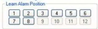
○ Alarms 1 to 4 ○ Alarms 1 to 8
Relay 2 Activation
○ Alarms 5 to 8 ○ Alarms 1 to 8
Relay 1 State
○ Normally Open ○ Normally Closed
Relay 2 State
○ Normally Open ○ Normally Closed
Re-arm Time (Secs)
○ 1 ○ 5 ○ 10 ○ 60
Set Relays
Pan/Tilt Position
Send Direct Command (Bytes must be in HEX and comma separated, without Header or CS)
Send Now
Bosch Security Systems Inc.
850 Greenfield Road
Lancaster
Pennsylvania 17601
USA
Phone +1 888-289-0096
Fax +1 585-223-9180
E-Mail: security.sales@us.bosch.com
www.boschsecurity.us
Europe, Middle East, Africa
Bosch Security Systems B.V.
P.O. Box 80002
5600 JB Eindhoven
Netherlands
Phone +31 40 2577 284
Fax +31 40 2577 330
de.securitysystems@bosch.com
www.boschsecurity.com
Bosch Security Systems Pte Ltd
38C Jalan Pemimpin
Singapore 577180
| DIGITAL_ZOOM_DISABLE | 43 |
| DIGITAL_ZOOM_ENABLE | 42 |
| AUTOFLIP_ON_PRESET | 41 |
| AUTOFLIP_OFF_PRESET | 40 |
| WASHWIPE_ON_PRESET | 39 |
| WASHWIPE_OFF_PRESET | 38 |
| AUTO_ALARM_ON_PRESET | 37 |
| AUTO_ALARM_OFF_PRESET | 36 |
| AUTO_LOWLIGHT_OFF_PRESET | 35 |
| CAMERA_COMMAND_PRESET1 | 34 |
| CAMERA_COMMAND_PRESET10 | 33 |
| CAMERA_RECALIBRATE_PRESET | 32 |
| RESET_PRESETS_PRESET | 31 |
| AUTOHOME_PRESET1_PRESET | 204 |
| SET TOUR1_PRESET | 211 |
| SET TOUR6_PRESET | 216 |
| PRIVACY_PRESET_START | 221 |
| AUTO_LOWLIGHT_ON_PRESET | 238 |
| PRIVACY_PRESET_END | 235 |
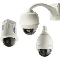
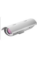
- MIC440 EXPLOSION PROTECTED CCTV CAMERA SYSTEM
- INSTALLATION AND OPERATION MANUAL
- CHAPTERS
- MIC440 EXPLOSION PROTECTED CCTV CAMERA SYSTEM | INSTALLATION AND OPERATION MANUAL
- EN
- INTRODUCTION
- HARDWARE INSTALLATION
- POWER SUPPLY INSTALLATION AND SETUP
- CONFIGURING THE MIC440 CAMERA
- TECHNICAL SPECIFICATIONS
- SAFETY PRECAUTIONS
- IMPORTANT SAFETY INSTRUCTIONS
- CAUTION
- WARNING
- REFERENCE
- APPENDICES
- CHAPTER 1 INTRODUCTION
- MIC440 CAMERA OPTIONS
- MIC440 POWER SUPPLY UNIT VERSIONS
- UNPACKING
- PACKAGE CONTENTS
- MIC440 EXPLOSION PROTECTED CCTV CAMERA SYSTEM INSTALLATION AND OPERATION MANUAL
- INSTALLATION ACCESSORIES
- KEY TO MIC-PMB DRAWING
- CHAPTER 2 HARDWARE INSTALLATION
- PRE-INSTALLATION PREPARATION IN THE WORKSHOP
- CABLE GLAND AND CABLE MOUNTING INSTRUCTIONS
- CAMERA INSTALLATION INSTRUCTIONS
- ELECTRICAL CONNECTIONS TO THE MIC
- EARTHING OF THE MIC440 CAMERA
- LIGHTNING PROTECTION
- MAINTENANCE
- ON SITE INSPECTION
- CHAPTER 3 POWER SUPPLY INSTALLATION & SETUP
- MIC-12PSU, MIC-240PSU, MIC-24PSU AND MIC-115 PSU
- HAZARDOUS AREA POWER SUPPLY INSTALLATION INSTRUCTIONS
- NON-HAZARDOUS AREA POWER SUPPLY INSTALLATION INSTRUCTIONS
- INSTALLATION OF THE MIC-PSU
- CONNECTING THE MIC-24PSU, MIC-240PSU, OR MIC-115PSU
- POWER SUPPLY LAYOUT AND CONNECTIONS
- DIMENSIONS
- PCB EARTH LINK
- FUSE RATINGS
- MIC-12PSU POWER SUPPLY UNIT
- OPTIONAL CARDS AND KITS FOR MIC440 CAMERAS
- CHAPTER 4 CONFIGURING THE MIC440 CAMERA
- CONNECTING THE MIC440 TO THE PC
- CONNECTING THE GREENWICH ADAPTOR
- CONNECTING THE KK SYSTEMS K2-ADE RS232 TO RS485/422 ADAPTOR
- CONNECTING THE MIC-USB485CVTR, USB TO RS485 CONVERTER
- MIC-USB485CVTR AND UNIVERSAL CAMSET SOFTWARE INSTALLATION
- COMMISSIONING THE MIC440 USING UNIVERSAL CAMSET
- BOOT MESSAGES
- MIC SETTINGS
- CURRENT ADDRESS
- CONFIGURE MIC COMMUNICATIONS
- NEW ADDRESS
- NEW PROTOCOL
- MIC440 EXPLOSION PROTECTED CCTV CAMERA SYSTEM| INSTALLATION AND OPERATION MANUAL
- NEW BAUD RATE
- RESET MIC
- RESET CAMSET
- MIC MODEL
- COMM PORT
- CAMSET BAUD RATE
- RTS
- COMMS MODE
- PAN, TILT AND ZOOM CONTROLS
- AUXILIARIES
- PRESET POSITIONS
- TOUR CONTROLS
- PRESET TOURS
- PATTERN TOURS
- SOFT STOPS AND NON DWELL ZONES
- NON-DWELL ZONE
- CLEAR
- PAN REVERSE
- TILT REVERSE
- IMAGE FLIP
- WASH WIPE
- AUTO ALARM
- MULTI ALARM
- PHOTOCELL IR
- CAMERA POWER
- DIGITAL ZOOM
- AUTO FLIP
- AUTO IR
- AUTO LOWLIGHT
- AUTO HOME CONTROLS
- OTHER CONTROLS
- LEARN WASH POSITION
- LEARN ALARM POSITION
- FIND END STOPS
- SHOW BOOT MESSAGE
- SELF DIAGNOSIS
- DEFAULT SETTINGS
- GET CURRENT MIC SETTINGS
- SAVE CURRENT MIC SETTINGS
- LOAD SETTINGS INTO CAMSET
- SET CURRENT SETTINGS TO MIC
- UPLOAD DEFAULT OPTIONS
- MULTI ALARM SETTINGS
- LEARN ALARM POSITIONS
- RELAY 1 ACTIVATION
- RELAY 2 ACTIVATION
- RELAY 1 STATE
- RELAY 2 STATE
- RE-ARM TIME (SECS)
- RELAY STATE, ACTIVATION AND RE-ARM
- LENS RECALIBRATION AND FRAME INTEGRATION
- FRAME INTEGRATION SETTINGS
- PRIVACY AND CAPTIONS
- PRIVACY CONTROLS
- MASKS ON / OFF
- CROSSHAIR ON / OFF
- SHOW / CLEAR MASK STYLE
- MASK / CLEAR WHOLE SCREEN
- MASK / CLEAR PIXEL
- SET CROSSHAIR
- SET MASK TYPE
- LOAD FACTORY DEFAULTS
- MIC CONFIGURATION
- BASIC CALIBRATION
- ZOOM ALIGNMENT
- DIRECT COMMAND
- SAVE CURRENT SETTINGS
- PRIVACY CALIBRATION
- CAPTIONS
- LOCATION AND COLOUR
- SET DEFAULT CAPTION
- TOGGLE CAPTIONS ON / OFF
- TOGGLE SECTOR / PRESET
- PRESET CAPTIONS
- SECTOR CAPTIONS
- ADVANCED SETTINGS
- TEMPERATURE AND HUMIDITY
- TIMERS
- CLEAR ALL STATISTICS
- MIC SERIAL NUMBER
- DOWNLOAD EEPROM TO FILE
- UPLOAD EEPROM FROM FILE
- MANUAL AND PRESET / GOTO CONTROLS
- POT TEST CONTROLS
- START
- STOP
- CLEAR TRACE
- RESET MEASUREMENTS
- SAVE PLOT
- ROTATION ANALYSER
- VISIBLE TRACES
- PAN / TILT POS
- PAN / TILT PWM
- PAN / TILT SPEED
- PSU LEVEL
- MOUSE POINT VALUES
- POT TEST PLOT AREA
- PLOT AREA CONTROLS
- LOG COMMUNICATIONS
- CAPTURE IN ASCII
- ASSUME NEW MESSAGE AFTER 50MS
- TIME STAMP DATA
- CLEAR COMMS
- SAVE DATA TO FILE
- SEND DIRECT COMMAND
- COMMUNICATIONS TESTING
- MIC COMMS
- CAM COMMS
- ALARMS
- DETECT ALL MICS
- SONY SET
- SONYSET CONTROLS
- SONYSET PRESET NUMBER
- GET PRESET FROM MIC
- SEND PRESET TO MIC
- EXECUTE THIS PRESET
- LOAD TABLE FROM FILE TO MIC
- SAVE TABLE FROM MIC TO FILE
- CLEAR TABLE
- MIC PROGRAMMER
- CHAPTER 5 TECHNICAL SPECIFICATIONS
- CAMERA MODULE
- X OPTICAL ZOOM MODULE
- OPERATIONAL
- COMMUNICATION & PROTOCOLS
- CONNECTIVITY
- MECHANICAL
- PHYSICAL
- ENVIRONMENTAL
- ELECTRICAL
- AVAILABLE OPTIONS
- ACCESSORIES
- APPROVALS
- ATEX CERTIFIED DIRECTIVE 94/9/EC EXD IIC T
- APPENDIX A - PROTOCOL PRESET CODES
- PRESET CODES
- PELCO
- DEFINE MENU_ON_OFF 63 //DONT CHANGE
- VCL
- CONTACT
- AMERICAS
- EUROPE, MIDDLE EAST, AFRICA
- ASIA-PACIFIC
- MIC-PSU INSTALLATION
Brand : BOSCH
Model : MIC440
Category : Surveillance Camera