
X3000 - Router LINKSYS - Free user manual and instructions
Find the device manual for free X3000 LINKSYS in PDF.
| Product Type | ADSL modem router/router only |
| Brand | LINKSYS |
| Model | X3000 |
| Wireless Standards | 802.11n (2.4 GHz), 802.11g, 802.11b |
| Ethernet Standards | 802.3, 802.3u |
| ADSL Standards | G.992.1 (G.DMT), G.992.2 (G.Lite), G.992.3 (ADSL2), G.992.5 (ADSL2+) for Annex A, B, M, L, U-R2 |
| Ports | 1 DSL port, 1 Cable port (Ethernet for external modem), 3 Ethernet ports (10/100), 1 Power port |
| Buttons | On/Off, Reset, Wi-Fi Protected Setup |
| LEDs | Power, Ethernet (1-3), Wi-Fi Protected Setup, Wireless, Internet |
| Cabling Type | CAT5, RJ-11 (for Annex A), RJ-45 (for Annex B) |
| Antennas | 2 internal |
| Modulations | 802.11b: CCK/QPSK, BPSK; 802.11g/n: OFDM/BPSK, QPSK, 16-QAM, 64-QAM |
| Transmit Power | 802.11b: 16 ± 1.5 dBm; 802.11g: 16 ± 1.5 dBm; 802.11n: 18 ± 1.5 dBm |
| Receive Sensitivity | 802.11b: -87 dBm @ 11 Mbps; 802.11g: -72 dBm @ 54 Mbps; 802.11n HT20: -71 dBm @ 130 Mbps; 802.11n HT40: -68 dBm @ 270 Mbps |
| Security Features | WPA2/WPA Personal and Enterprise, WEP 128/64-bit, MAC Filtering, SPI Firewall |
| Dimensions (L x W x H) | 202 x 160 x 34 mm |
| Weight | 287 g |
| Power Supply | 12 VDC, 1 A |
| Operating Temperature | 0 to 40 °C |
| Storage Temperature | -20 to 70 °C |
| Operating Humidity | 10 to 85% (non-condensing) |
| Storage Humidity | 5 to 90% (non-condensing) |
Frequently Asked Questions - X3000 LINKSYS
User questions about X3000 LINKSYS
0 question about this device. Answer the ones you know or ask your own.
Ask a new question about this device
Download the instructions for your Router in PDF format for free! Find your manual X3000 - LINKSYS and take your electronic device back in hand. On this page are published all the documents necessary for the use of your device. X3000 by LINKSYS.
USER MANUAL X3000 LINKSYS
Top .4
Back. 5
Bottom. 5
Wall-mounting placement. 5
Installation
Set up your modem-router .6
Connect your modem-router 6
7
Advanced Configuration
How to access the browser-based utility. .8
How to use the browser-based utility. .8
Setup > Basic Setup. 9
Auto/ADSL mode 9
Ethernet mode 10
Manual setup 11
Wi-Fi Protected Setup 13
Wireless > Wireless Security 14
Personal Options 14
Office Options 14
Wireless Security 14
Wireless > Guest Access 17
Guest Access 18
Guest Instructions 18
Troubleshooting
X2000. 19
Specifications
X2000. 21
Appendix: Linksys X2000 Advanced Settings
X2000. 22
Product Overview
Top


Ethernet If the LED is continuously lit, the Modem Router is successfully connected to a device through that port.

Wi-Fi Protected Setup™ Button Press this button to have Wi-Fi Protected Setup™ search for your Wi-Fi Protected Setup™-supported wireless device. The LED is continuously lit when a Wi-Fi Protected Setup™ connection is successfully established. The LED blinks slowly while Wi-Fi Protected Setup™ is setting up a connection, and blinks rapidly in amber if an error occurs. The LED is off when Wi-Fi Protected Setup™ is idle.

Wireless The Wireless LED lights up when the wireless feature is enabled. It flashes when the Modem Router is actively sending or receiving data over the network.

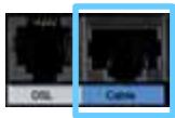
WAN Lights up white when the modem router is connected directly to an ADSL line. Lights up blue when the modem router is set up as a router only and is connected to the internet through a separate modem.

Power The Power LED lights up when the modem router is powered on. When the modem router goes through its self-diagnostic mode during every boot-up, the LED flashes. When the diagnostic is complete, the LED is continuously lit.
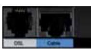
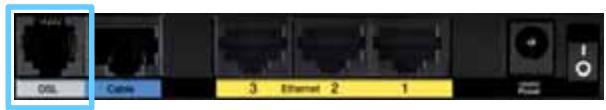
Back


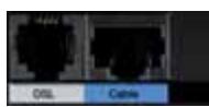
DSL—Connects to the ADSL line.

Cable—To use the modem router as only a router, use a network cable to connect this port to a separate modem's LAN/Ethernet port.

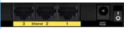
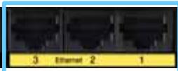
Ethernet—Using Ethernet cables (also called network cables), these Ethernet ports connect the modem router to computers and other Ethernet network devices on your wired network.

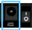
Power—The Power port connects to the included power adapter.

Power button—Press | (on) to turn on the modem router.
Bottom
- Reset—This button allows you to reset the router to its factory defaults. Press and hold the Reset button for approximately five seconds.
Wall-mounting placement
The Router has two wall-mount slots on its bottom panel. The distance between the slots is 175.56 mm. Two screws are needed to mount the Router.
Suggested Mounting Hardware

4-5 mm

2.5-3.0 mm

1-1.5 mm
NOTE
Cisco is not responsible for damages incurred by unsecured wallmounting hardware.
Follow these instructions:
- Determine where you want to mount the Router. Make sure that the wall you use is smooth, flat, dry, and sturdy. Also make sure the location is within reach of an electrical outlet.
- Drill two holes into the wall. Make sure the holes are 175mm apart.
- Insert a screw into each hole and leave 3mm of its head exposed.
- Position the Router so the wall-mount slots line up with the two screws.
- Place the wall-mount slots over the screws and slide the Router down until the screws fit snugly into the wall-mount slots.
Wall-mounting template
Print this page at 100% size.
Cut along the dotted line, and place on the wall to drill precise spacing.
175 mm
Installation
Set up your modem-router
NOTE
Run the Setup CD-ROM to install the modem-router. If you cannot run the Setup CD-ROM, refer to the steps below.
NOTE
If you are setting up your modem-router in New Zealand, see "NOTE FOR USERS IN NEW ZEALAND" on page 7.
Connect your modem-router
To connect your modem-router:
- Power down all your network devices, including your computer(s) and the modem-router. If you currently use a modem, disconnect it now—the modem-router replaces your modem.
- Connect one end of the provided Ethernet cable to your computer's Ethernet adapter and the other end to an Ethernet port on the back of the modem-router.


- Repeat step 2 for each additional computer or device that you want to connect to the modem-router.
NOTE
If your computer's Ethernet adapter is not set up, refer to the Ethernet adapter's documentation for more information.
- Connect one end of the phone cable to the DSL port on the back.
- Connect the other end of the phone cable to the wall jack with ADSL service or microfilter.
NOTE
If you experience static on your phone line, you may need a microfilter or splitter. (This is required for users in the UK; other users should contact their ISPs to verify. ISDN users do not need a microfilter.) If you require a microfilter, you must install one for each phone or fax that you use. To install a microfilter, plug it into a phone jack that has ADSL service, then connect one end of the provided phone cable to the microfilter's DSL port.
- Connect one end of the power adapter cord to the Power port and the other end to the electrical outlet.
- Power on the computer that you will use to configure the modem-router.
- The LEDs for Power, Wireless, and Ethernet (one for each connected computer) should light up. If not, make sure the modem-router is powered on and the cables are securely connected.
Set up your modem-router as only a router
NOTE
Run the Setup CD-ROM to install the modem-router. If you cannot run the Setup CD-ROM, refer to the steps below.
To set up your modem-router as a router:
- Connect one end of the provided Ethernet cable to your computer's Ethernet adapter and the other end to an Ethernet port on the back of the modem-router.


- Connect one end of an Ethernet cable to the Cable port on the back of the modem-router, then connect the other end to an available Ethernet/ LAN port on your modem.
- Connect one end of the power adapter cord to the Power port and the other end to the electrical outlet.


- Power on the computer that you will use to configure the modem-router.
- The LEDs for Power, Wireless, and Ethernet (one for each connected computer) should light up. If not, make sure the modem-router is powered on and the cables are securely connected.
NOTE FOR USERS IN NEW ZEALAND
To set up the device, follow these instructions:
- Access the Setup > Basic Setup screen.
- Select RFC 2364 PPPoA from the Encapsulation drop-down menu.
- For the Virtual Circuit ID, enter 0 for the VPI and 100 for the VCI.
- Select VC for Multiplexing.
- Select Multimode from the DSL Modulation drop-down menu.
- Enter your User Name and Password details from your ISP.
- Click Save Settings.
Advanced Configuration
After setting up the router with the setup software (located on the CD-ROM), the router will be ready for use. If you would like to change its advanced settings, or if the software does not run, use the router's browser-based utility. You can access the utility via a web browser on a computer connected to the router. For more help with the utility, click Help on the right side of the screen or go to our website.
How to access the browser-based utility
- To access the browser-based utility, launch the web browser on your computer, and enter the router's default Internet Protocol (IP) address, 192.168.1.1, in the Address field. Then press Enter.
NOTE
You can also access the browser-based utility on Windows computers by entering the device name in the Address field.
A login screen appears. (A similar screen appears for non-Windows 7 users.)
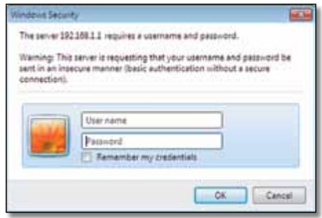
- In the User name field, enter admin.
- In the Password field, enter the password created by the setup software. If you did not run the setup software, then enter the default, admin.
NOTE
You can also access the browser-based utility through Cisco Connect.
- Click OK to continue.
How to use the browser-based utility
Use the tabs at the top of each screen to navigate within the utility. The tabs are arranged in two levels, top-level tabs for general functions and lower-level tabs for the corresponding specific functions.

The top-level tabs are: Setup, Wireless, Security, Access Restrictions, Applications & Gaming, Administration, and Status. Each of these has its own unique, lower-level tabs.
NOTE
Within this User Guide, each screen is identified by its top- and lower-level tab names. For example, "Setup > Basic Setup" is the screen accessed via the Setup top-level tab, and its Basic Setup lower-level tab.
If you change any settings on a screen, you must click Save Settings to apply your changes, or click Cancel Changes to clear your changes. These controls are located at the bottom of each screen.

NOTE
To learn more about any field, click Help on the right side of the screen.
Setup > Basic Setup
The first screen that appears is the Basic Setup screen. This allows you to change the router's general settings.
Auto/ADSL mode
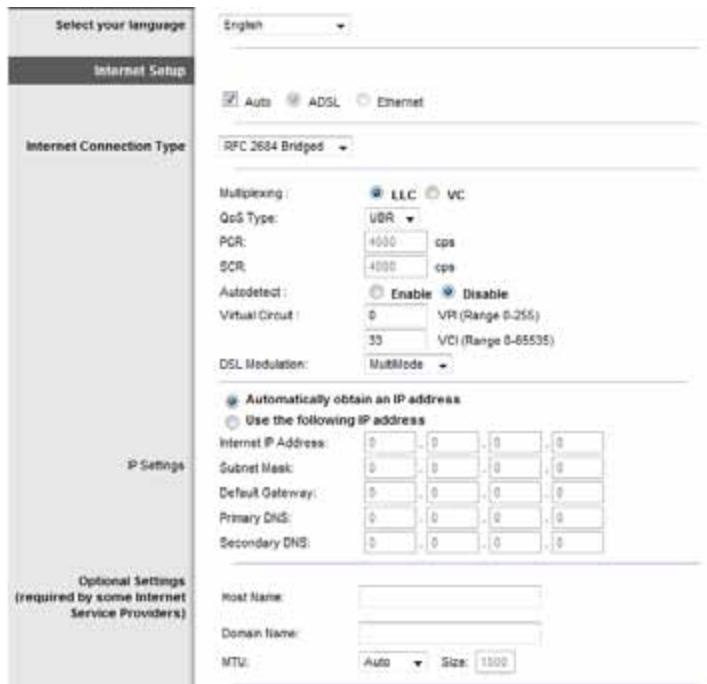
ADSL mode (default) has the following fields that should be completed:
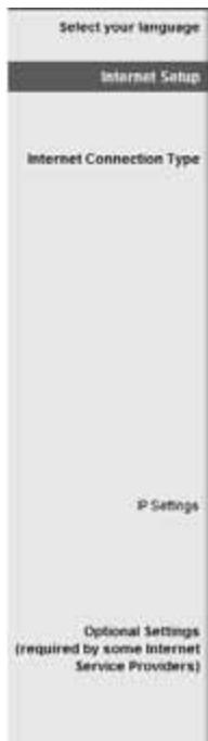
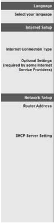
Language
Select your language To use a different language, select one from the dropdown menu. The language of the browser-based utility will change five seconds after you select another language.
Internet Setup
The Internet Setup section configures the router to your Internet connection. Most of this information can be obtained through your Internet Service Provider (ISP).
Internet Connection Type
Select the type of Internet connection your ISP provides from the drop-down menu. The available types are:
- Bridged Mode Only
RFC 2684 Bridged
RFC2684 Routed - IPOA
RFC2516PPPoE
RFC2364 PPPoA
Bridged Mode Only
In this mode, only the DSL modem function is available, and all Gateway features are disabled. If selected, you only need to enter the VC Settings.
RFC 2684 Bridged
If selected, enter the correct data for the IP Settings. Select Obtain an IP address automatically if your ISP allocates an IP address upon connection. Otherwise, select Use the following IP address.
RFC2684 Routed
With this method, you are required to use a permanent IP address to connect to the Internet.
IPoA
IPoA (IP over ATM) uses a fixed IP address.
RFC 2516 PPPoE
Some DSL-based ISPs use PPPoE (Point-to-Point Protocol over Ethernet) to establish Internet connections. If you are using PPPoE, your IP address is provided automatically.
RFC2364 PPPoA
Some DSL-based ISPs use PPPoA (Point-to-Point Protocol over ATM) to establish Internet connections. If using PPPoA, your IP address is provided automatically.
Network Setup
The Network Setup section configures the IP settings for your local network.
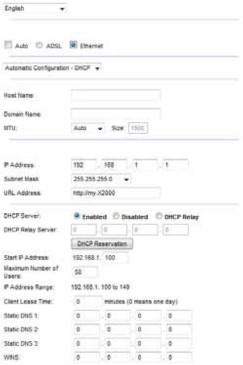
Ethernet mode
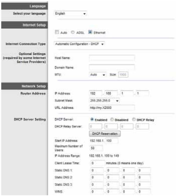
If you select Ethernet (router-only) mode, the following fields are available:
Language
Select your language To use a different language, select one from the dropdown menu. The language of the browser-based utility will change five seconds after you select another language.
Internet Setup
The Internet Setup section configures the router to your Internet connection. Most of this information can be obtained through your Internet Service Provider (ISP).
Internet Connection Type
Select the type of Internet connection your ISP provides from the drop-down menu. The available types are:
Automatic Configuration - DHCP
Static IP
- PPPoE
PPTP
L2TP
- Telstra Cable
Automatic Configuration - DHCP
The default Internet Connection Type is Automatic Configuration - DHCP (Dynamic Host Configuration Protocol). Keep the default only if your ISP supports DHCP or if you connect using a dynamic IP address. (This option usually applies to cable connections.)
Static IP
If you are required to use a fixed IP address to connect to the Internet, select Static IP.
PPPoE
If you have a DSL connection, check whether your ISP uses Point-to-Point Protocol over Ethernet (PPPoE). If so, select PPPoE.
Connect on Demand or Keep Alive
The Connect on Demand and Keep Alive options let you choose whether the router connects to the Internet only as needed (useful if your ISP charges for connect time), or if the router should always be connected. Select the appropriate option.
PPTP
Point-to-Point Tunneling Protocol (PPTP) is a service that generally applies to connections in Europe.
If your PPTP connection supports DHCP or a dynamic IP address, then select Obtain an IP Address Automatically. If you are required to use a fixed IP address to connect to the Internet, then select Specify an IP Address and configure the options below.
L2TP
Layer 2 Tunneling Protocol (L2TP) is a service that generally applies to connections in Israel.
Telstra Cable
Telstra Cable is a service that generally applies to connections in Australia.
Network Setup
The Network Setup section configures the IP settings for your local network.
Wireless > Basic Wireless Settings
NOTE
To learn more about any field, click Help on the right side of the screen.
The basic settings for wireless networking are set on this screen.
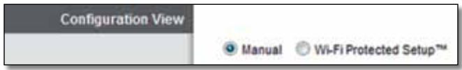
There are two ways to configure the Router's wireless network(s), manual and Wi-Fi Protected Setup.
Wi-Fi Protected Setup is a feature that makes it easy to set up your wireless network. If you have client devices, such as wireless adapters, that support Wi-Fi Protected Setup, then you can use Wi-Fi Protected Setup.
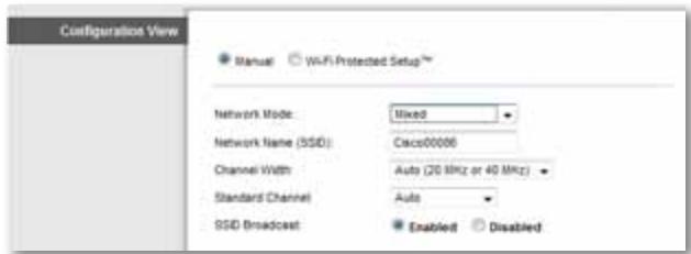
Configuration View To manually configure your wireless networks, select Manual.
Manual setup
Set up the wireless network on this screen.
NOTE
After you set up the wireless network(s), set up the wireless security settings. Go to "Wireless > Wireless Security" on page 14.
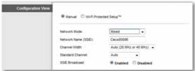
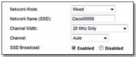
Network Mode In most network configurations, you should leave it set to Mixed (default).
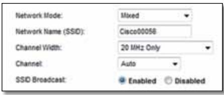
Wireless settings
Basic Wireless Settings (Manual) > Wireless Settings
Network Mode Select the wireless standards your network will support.
- Mixed If you have Wireless-N, Wireless-G, and Wireless-B devices in your network, keep the default, Mixed.
- Wireless-B/G Only If you have both Wireless-B and Wireless-G devices in your network, select Wireless-B/G Only.
- Wireless-B Only If you have only Wireless-B devices, select Wireless-B Only.
- Wireless-G Only If you have only Wireless-G devices, select Wireless-G Only.
- Wireless-N Only If you have only Wireless-N devices, select Wireless-N Only.
- Disabled If you have no Wireless-B, Wireless-G, and Wireless-N devices in your network, select Disabled.
NOTE
If you are not sure which mode to use, keep the default, Mixed.
Network Name (SSID) The Service Set Identifier (SSID) is the network name shared by all devices in a wireless network. It is case-sensitive and must not exceed 32 keyboard characters. The default is Cisco followed by the last 5 digits of the router's serial number, which is found on the bottom of the router. If you used the setup software for installation, then the default Network Name is changed to an easy-to-remember name.
NOTE
If you restore the router's factory default settings (by pressing the Reset button or using the Administration > Factory Defaults screen), the Network Name will return to its default value, and all devices on your wireless network will need to be reconnected.
ChannelWidth For best performance in a network using Wireless-B, Wireless-G and Wireless-N devices, select Auto (20 MHz or 40 MHz). For a channel width of 20 MHz, keep the default, 20 MHz only.
Channel Select the channel from the drop-down list for Wireless-B, Wireless-G, and Wireless-N networking. If you are not sure which channel to select, then keep the default, Auto.
SSID Broadcast When wireless clients survey the local area for wireless networks to associate with, they will detect the SSID broadcast by the router. To broadcast the router's SSID, keep the default, Enabled. If you do not want to broadcast the router's SSID, then select Disabled.
Wi-Fi Protected Setup
Three methods of Wi-Fi Protected Setup are available. Use the method that applies to the client device you are configuring.
NOTE
Wi-Fi Protected Setup configures one client device at a time. Repeat the instructions for each client device that supports Wi-Fi Protected Setup.
Wi-Fi Protected Setup light activity
- The Cisco logo on the top panel of the router functions as the Wi-Fi Protected Setup light.
- When the Wi-Fi Protected Setup process is active, the light flashes slowly.
- When the Wi-Fi Protected Setup is successful, the light is continuously lit.
If there is an error, the light flashes quickly for two minutes; please wait and try again. -
Wait until the light is continuously lit, before starting the next Wi-Fi Protected Setup session.
-
Wi-Fi Protected Setup Button Use this method if your client device has a Wi-Fi Protected Setup button.
NOTE
Make sure you configure one client device at a time.
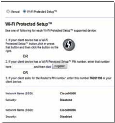
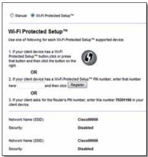
Wi-Fi Protected SetupTM
Use one of following for each Wi-Fi Protected Setup™ supported device:
- If your client device has a Wi-Fi
Protected SetupTM button, click or press
that button and then click the button on the right.

a. Click or press the Wi-Fi Protected Setup button on the client device.
b. Click the Wi-Fi Protected Setup button on the router's Wi-Fi Protected Setup screen, OR press and hold the Wi-Fi Protected Setup button on the back panel of the router for one second.
c. After the client device has been configured, click OK on the router's Wi-Fi Protected Setup screen within two minutes.
- Enter Client Device PIN on Router Use this method if your client device has a Wi-Fi Protected Setup PIN (Personal Identification Number).
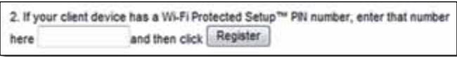
a. Enter the PIN from the client device in the field on the router's Wi-Fi Protected Setup screen.
b. Click the Register button on the router's Wi-Fi Protected Setup screen.
c. After the client device has been configured, click OK on the router's Wi-Fi Protected Setup screen within two minutes.
-
Enter Router PIN on Client Device Use this method if your client device asks for the router's PIN.
-
If your client asks for the Router's PIN number, enter this number 76201196 in your client device.
a. On the client device, enter the PIN listed on the router's Wi-Fi Protected Setup screen. (It is also listed on the bottom of the router.)
b. After the client device has been configured, click OK on the router's Wi-Fi Protected Setup screen within two minutes.
For each wireless network, the Network Name (SSID), Security, and Passphrase are displayed at the bottom of the screen.
NOTE
If you have client devices that do not support Wi-Fi Protected Setup, note the wireless settings, and then manually configure those client devices.
Wireless > Wireless Security
The wireless security settings configure the security of your wireless network(s). The router supports the following wireless security options: WPA2/WPA Mixed Mode, WPA2 Personal, WPA Personal, WPA2/WPA Enterprise Mixed Mode, WPA2 Enterprise, WPA Enterprise, WEP, and RADIUS. (WPA stands for Wi-Fi Protected Access. WEP stands for Wireless Equivalent Privacy. RADIUS stands for Remote Authentication Dial-In User Service.)
NOTE
To learn more about any field, click Help on the right side of the screen.
Personal Options
| Security Option | Strength |
| WPA2 Personal | Strongest |
| WPA2/WPA Mixed Mode | WPA2: Strongest WPA: Strong |
| WPA Personal | Strong |
| WEP | Basic |
Office Options
The office options are available for networks that use a RADIUS server for authentication. The office options are stronger than the personal options because WPA2 or WPA provides encryption while RADIUS provides authentication.
| Security Option | Strength |
| WPA2 Enterprise | Strongest |
| WPA2/WPA Enterprise Mixed Mode | WPA2: Strongest WPA: Strong |
| WPA Enterprise | Strong |
| RADIUS | Basic |
Wireless Security
Wireless security is strongly recommended, and WPA2 is the strongest method available. Use WPA2 if it is supported by all of your wireless devices.
Security Mode
Select the security option for your wireless network. Then go to the instructions for your selection.
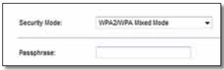
WPA2/WPA Mixed Mode
NOTE
If you select WPA2/WPA Mixed Mode as your Security Mode, each device in your wireless network MUST use WPA2/WPA and the same passphrase.
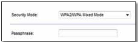
Passphrase Enter a passphrase of 8-63 characters. The default is password. If you used the setup software for installation, then the default is changed to a unique passphrase.
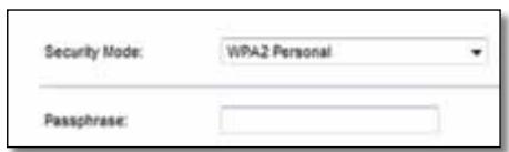
WPA2 Personal
NOTE
If you select WPA2 Personal as your Security Mode, each device in your wireless network MUST use WPA2 Personal and the same passphrase.
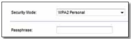
Passphrase Enter a passphrase of 8-63 characters. The default is password. If you used the setup software for installation, then the default is changed to a unique passphrase.
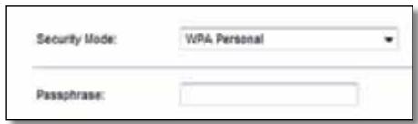
WPA Personal
NOTE
If you select WPA Personal as your Security Mode, each device in your wireless network MUST use WPA Personal and the same passphrase.
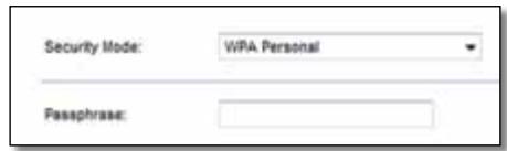
Passphrase Enter a passphrase of 8-63 characters. The default is password. If you used the setup software for installation, then the default is changed to a unique passphrase.
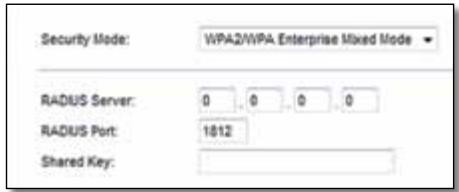
WPA2/WPA Enterprise Mixed Mode
This option features WPA2/WPA used in coordination with a RADIUS server. (This should only be used when a RADIUS server is connected to the router.)
NOTE
If you select WPA2/WPA Enterprise Mixed Mode as your Security Mode, each device in your wireless network MUST use WPA2/WPA Enterprise and the same shared key.
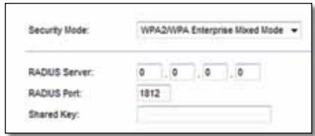
RADIUS Server Enter the IP address of the RADIUS server.
RADIUS Port Enter the port number of the RADIUS server. The default is 1812.
Shared Key Enter the key shared between the router and the server.
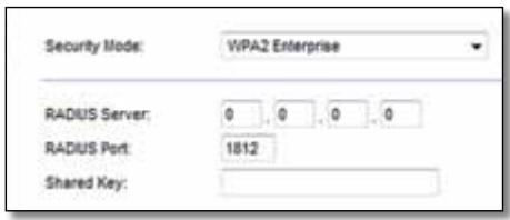
WPA2 Enterprise
This option features WPA2 used in coordination with a RADIUS server. (This should only be used when a RADIUS server is connected to the router.)
NOTE
If you select WPA2 Enterprise as your Security Mode, each device in your wireless network MUST use WPA2 Enterprise and the same shared key.
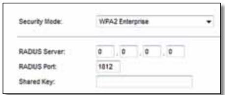
RADIUS Server Enter the IP address of the RADIUS server.
RADIUS Port Enter the port number of the RADIUS server. The default is 1812.
Shared Key Enter the key shared between the router and the server.
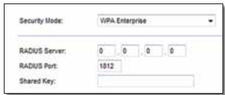
WPA Enterprise
This option features WPA used in coordination with a RADIUS server. (This should only be used when a RADIUS server is connected to the router.)
NOTE
If you select WPA Enterprise as your Security Mode, each device in your wireless network MUST use WPA Enterprise and the same shared key.
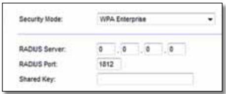
RADIUS Server Enter the IP address of the RADIUS server.
RADIUS Port Enter the port number of the RADIUS server. The default is 1812.
Shared Key Enter the key shared between the router and the server.
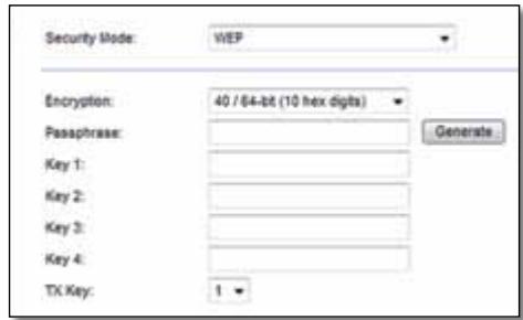
WEP
WEP is a basic encryption method, which is not as secure as WPA.
NOTE
If you select WEP as your Security Mode, each device in your wireless network MUST use WEP and the same encryption and shared key.
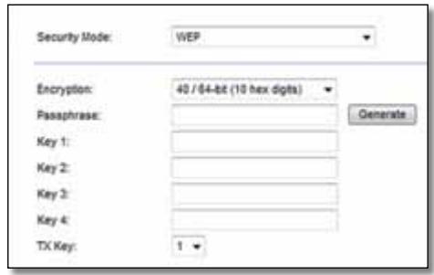
Encryption Select a level of WEP encryption, (40/64-bit 10 hex digits) or 104/128-bit (26 hex digits). The default is 40/64-bit (10 hex digits).
Passphrase Enter a passphrase to automatically generate WEP keys. Then click Generate.
Key 1-4 If you did not enter a passphrase, enter the WEP key(s) manually.
TX Key Select a default TX (Transmit) Key to use. The default is 1.
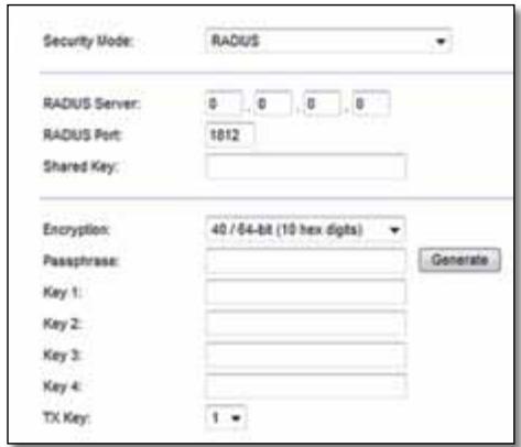
RADIUS
This option features WEP used in coordination with a RADIUS server. (This should only be used when a RADIUS server is connected to the router.)
NOTE
If you select RADIUS as your Security Mode, each device in your wireless network MUST use RADIUS and the same encryption and shared key.
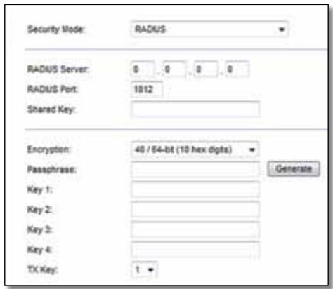
RADIUS Server Enter the IP address of the RADIUS server.
RADIUS Port Enter the port number of the RADIUS server. The default is 1812.
Shared Secret Enter the key shared between the router and the server.
Encryption Select a level of WEP encryption, (40/64-bit 10 hex digits) or 104/128-bit (26 hex digits). The default is 40/64-bit (10 hex digits).
Passphrase Enter a passphrase to automatically generate WEP keys. Then click Generate.
Key 1-4 If you did not enter a passphrase, enter the WEP key(s) manually.
TX Key Select a default TX (Transmit) Key to use. The default is 1.
Disabled
If you choose to disable wireless security, you will be informed that wireless security is disabled when you first attempt to access the Internet. You will given the option to enable wireless security, or confirm that you understand the risks but still wish to proceed without wireless security.
NOTE
When wireless security is disabled, anyone can access your wireless network at any time.

Wireless > Guest Access
The Guest Access feature allows you to provide guests visiting your home with Internet access via wireless. The guest network is a wireless network separate from your local network. The Guest Access feature does not provide access to the local network and its resources, so your guests will not have access to your computers or personal data. For example, the guest computer cannot print to a printer on the local network or copy files to a computer on the local network. This helps minimize exposure of your local network.
NOTE
To learn more about any field, click Help on the right side of the screen.
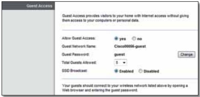
Guest Access
Allow Guest Access To allow Internet access through a guest network, keep the default, yes. Otherwise, select no.
Guest Network Name The default is the name of your wireless network, followed by -guest.
Guest Password The default is guest. If you used the setup software for installation, then the default is changed to a unique password.
Change Click this option to change the Guest Password. The Change Guest Password screen appears.
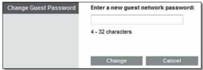
Change Guest Password
- Enter a new guest network password Enter a password of 4-32 characters.
Then click Change to save the new password and return to the Guest Access screen.
Total Guests Allowed By default, 5 guests are allowed Internet access through the guest network. Select the number of guests you want to allow on your guest network.
SSID Broadcast When wireless devices survey the local area for wireless networks to associate with, they will detect the SSID (wireless network name) broadcast by the router. To broadcast the SSID of the guest network, keep the default, Enabled. If you do not want to broadcast the SSID of the guest network, then select Disabled.
Guest Instructions
When a guest wants Internet access in your home, provide these instructions:
- On the guest computer, connect to the wireless guest network named on the Guest Access screen.
- Open a web browser.
- On the login screen, enter the password displayed on the Guest Access screen.
- Click Login.
Troubleshooting
X2000
Your computer cannot connect to the Internet.
Follow the instructions until your computer can connect to the Internet:
- Make sure that the Modem Router is powered on. The Power LED should be green and not flashing.
- If the Power LED is flashing, then power off all of your network devices, including the Modem Router and computers. Then power on each device in the following order:
a. Modem Router
b. Computer
- Check the LEDs on the device's front panel. Make sure the Power, DSL, and at least one of the numbered Ethernet LEDs are lit. If they are not, then check the cable connections. The computer should be connected to one of the Ethernet ports numbered 1-4 on the device, and the device's DSL port must be connected to the ADSL line.
When you double-click the web browser, you are prompted for a user name and password. If you want to get rid of the prompt, follow these instructions.
Launch the web browser and perform the following steps (these steps are specific to Internet Explorer but are similar for other browsers):
- Select Tools > Internet Options.
- Click the Connections tab.
- Select Never dial a connection.
- Click OK.
You are using a static IP address and cannot connect.
Refer to Windows Help and change your Internet Protocol (TCP/IP) Properties to Obtain an IP address automatically.
The computer cannot connect wirelessly to the network.
Make sure the wireless network name or SSID is the same on both the computer and the device. If you have enabled wireless security, then make sure the same security method and key are used by both the computer and the device.
You need to modify the basic settings on the device.
Run the Setup Wizard on the Setup CD-ROM.
You need to modify the advanced settings on the device.
Open the web browser (for example, Internet Explorer or Firefox), and enter the device's IP address in the address field (the default IP address is 192.168.1.1). When prompted, complete the User name and Password fields (the default user name and password is admin). Click the appropriate tab to change the settings
You cannot use the DSL service to connect manually to the Internet.
After you have installed the router, it will automatically connect to your Internet Service Provider (ISP), so you no longer need to connect manually.
When you open the web browser, the login screen appears, even though you do not need to log in.
These steps are specific to Internet Explorer but are similar for other browsers.
- Open the web browser.
- Go to Tools > Internet Options.
- Click the Connections tab.
- Select Never dial a connection.
- Click OK.
The router does not have a coaxial port for the cable connection.
A coaxial cable can connect to only a cable modem. Your modem router works as a modem with your ADSL Internet, but if you have cable Internet, your modem router should be connected to a separate cable modem. Insert the Setup CD into your computer and follow the on-screen instructions to connect your modem-router to a cable modem.
You want to access the browser-based utility from Cisco Connect.
To enter the browser-based utility from Cisco Connect, follow these steps:
- Open Cisco Connect.
- On the main menu, click Router settings.
- Click Advanced settings.
- Write down the username and password that are displayed. (To help protect your password, you can copy it to the Clipboard by clicking Copy password.)
- Click OK.
When you try to log into the browser-based utility, your password does not work.
Your wireless security password also serves as the browser-based utility's login password. To see this password:
- Open Cisco Connect.
- On the main menu, click Router settings.
- The Password is displayed on the left side of the screen.
In Windows XP, you do not see the router in the My Network Places screen.
In the Network Tasks section, click Show icons for networked UPnP devices. If the router does not appear, follow these instructions:
- Go to Start > Control Panel > Firewall.
- Click the Exceptions tab.
- Select UPnP Framework.
- Click OK.
WEB If your questions are not addressed here, refer to the website, linksys.com/support
Specifications
X2000
| Standards | WLAN: 802.11n, 802.11g, 802.11b Ethernet: 802.3, 802.3u ADSL: T1.413i2, G.992.1 (G.DMT), G.992.2 (G.Lite), G.992.3 (ADSL2), G.992.5 (ADSL2+) for Annex A, B, M, L, U-R2 for Annex B |
| Ports | DSL, Cable, Ethernet (1-3), Power |
| Buttons | On/Off, Reset, Wi-Fi Protected Setup™ |
| LEDs | Power, Ethernet (1-3), Wi-Fi Protected Setup, Wireless, Internet |
| Cabling Type | CAT5, RJ-11 (for Annex A), RJ-45 (for Annex B) |
| Antennas | 2 Internal |
| Modulations | 802.11b: CCK/QPSK, BPSK 802.11g: OFDM/BPSK, QPSK, 16-QAM, 64-QAM 802.11n: OFDM/BPSK, QPSK, 16-QAM, 64-QAM |
| Transmit Power | 802.11b: 16 ± 1.5 dBm 802.11g: 16 ± 1.5 dBm 802.11n: 18 ± 1.5 dBm |
| Receive Sensitivity | 802.11b: -87 dBm (typical) @ 11 Mbps 802.11g: -72 dBm (typical) @ 54 Mbps 802.11n HT20: -71 dBm (typical) @ 130 Mbps 802.11n HT40: -68 dBm (typical) @ 270 Mbps |
| Security Features | WPA2TM/WPA™ Personal and Enterprise; 128, 64 bits WEP; MAC Address Filtering; SPI Firewall |
| OS Requirements (for Setup wizard) | Windows 7, Windows Vista, Windows Vista 64-bit edition (with Network Magic and Setup Wizard), or Windows XP Mac OS X 10.5 or higher |
Environmental
| Dimensions | 202 x 34 x 160 mm (8.0" x 1.3" x 6.3") |
| Weight | 287 g (10.1 oz) |
| Power | 12VDC, 1A |
| Certification | FCC, CE, Telepermit, K.21, UL, CB, Wi-Fi (802.11b/g), WPA™, WPA2™, WMM, Wi-Fi Protected Setup™ |
| Operating Temperature | 0 to 40°C (32 to 104°F) |
| Storage Temperature | -20 to 70°C (-4 to 158°F) |
| Operating Humidity | 10 to 85% Noncondensing |
| Storage Humidity | 5 to 90% Noncondensing |
NOTES
For regulatory, warranty, and safety information, see the CD that came with your modem router or go to Linksys.com/support.
Specifications are subject to change without notice.
Maximum performance derived from IEEE Standard 802.11 specifications. Actual performance can vary, including lower wireless network capacity, data throughput rate, range and coverage. Performance depends on many factors, conditions and variables, including distance from the access point, volume of network traffic, building materials and construction, operating system used, mix of wireless products used, interference and other adverse conditions.
Appendix: Linksys X2000 Advanced Settings
X2000
NOTE
The information in this appendix is only necessary for users who connect the Linksys X2000 directly to a DSL line.
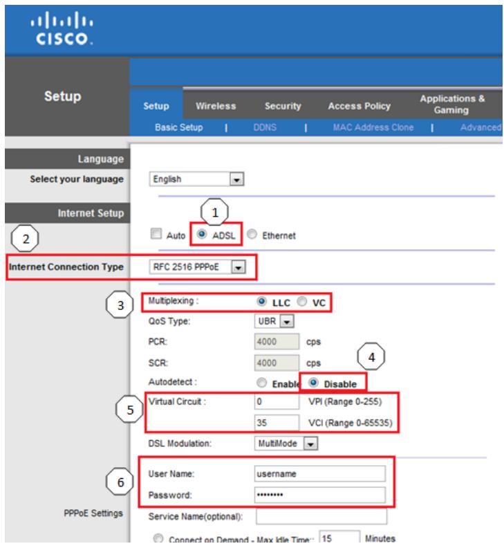
In your router's Advanced Settings, use the Setup tab to enter information about your Internet connection. If you don't know this information, contact your Internet Service Provider (ISP) or see the table on the next page for common settings.
- Select ADSL
- Internet Connection Type (PPPoE, PPPoA, etc.)
- Multiplexing (LLC / VC)
- AutoDetect
- Virtual Circuit (VPI/VCI)
- User name and password
| Country | Service Provider Name | Encapsulation | Multiplexing (LLC or VC) | VPI | VCI |
| APAC | |||||
| Australia | iiNet | PPPoE RFC2516 Embedded | LLC | 8 | 35 |
| Internode | PPPoE RFC2516 Embedded | LLC | 8 | 35 | |
| Optus | PPPoE RFC2516 Embedded | LLC | 8 | 35 | |
| Primus | PPPoE RFC2516 Embedded | LLC | 8 | 35 | |
| Soul | PPPoA - RFC2364 | VCMUX | 8 | 35 | |
| Telstra | PPPoE RFC2516 Embedded | LLC | 8 | 35 | |
| TPG | PPPoE RFC2516 Embedded | LLC | 8 | 35 | |
| Default-Other | PPPoE RFC2516 Embedded | LLC | 8 | 35 | |
| New Zealand | Default-Other | PPPoA - RFC2364 | VCMUX | 0 | 100 |
| EMEA | |||||
| Belgium | Academic Broadband | PPPoE | LLC | 8 | 35 |
| Belgacom | PPPoE | LLC | 8 | 35 | |
| Scarlet | PPPoA | VC | 8 | 35 | |
| Skynet | PPPoE | LLC | 8 | 35 | |
| Tele2 | PPPoE | LLC | 8 | 35 | |
| Default-Other | PPPoE | LLC | 8 | 35 | |
| Germany | 1 & 1 | PPPoE | LLC | 1 | 32 |
| AOL | PPPoE | LLC | 1 | 32 | |
| Arcor | PPPoE | LLC | 1 | 32 | |
| Compuserve | PPPoE | LLC | 1 | 32 | |
| Congster | PPPoE | LLC | 1 | 32 | |
| Freenet | PPPoE | LLC | 1 | 32 | |
| GMX | PPPoE | LLC | 1 | 32 | |
| Hanse Net - Alice | PPPoE | LLC | 1 | 32 | |
| HTP | PPPoE | LLC | 1 | 32 | |
| Lycos | PPPoE | LLC | 1 | 32 | |
| NetCologne | PPPoE | LLC | 8 | 35 | |
| Tiscali | PPPoE | LLC | 1 | 32 | |
| T-Online | PPPoE | LLC | 1 | 32 | |
| Country | Service Provider Name | Encapsulation | Multiplexing (LLC or VC) | VPI | VCI |
| Versatel | PPPoE | LLC | 1 | 32 | |
| Default-Other | PPPoE | LLC | 1 | 32 | |
| Italy | Albacom | PPPoA - RFC2364 | VCMUX | 8 | 35 |
| Aruba | PPPoA - RFC2364 | VCMUX | 8 | 35 | |
| Bisnet | RFC 1483 Routed | LLC | 8 | 35 | |
| MC-link | PPPoA - RFC2364 | VCMUX | 8 | 35 | |
| Nextra | PPPoA - RFC2364 | VCMUX | 8 | 35 | |
| Telecom Italia | PPPoA - RFC2364 | LLC | 8 | 35 | |
| TELE2 | PPPoA - RFC2364 | VCMUX | 8 | 35 | |
| Telvia | PPPoA - RFC2364 | VCMUX | 8 | 35 | |
| Tiscali | PPPoA - RFC2364 | VCMUX | 8 | 35 | |
| Wind | PPPoA - RFC2364 | VCMUX | 8 | 35 | |
| Default-Other | PPPoA - RFC2364 | VCMUX | 8 | 35 | |
| Luxembourg | Default-Other | PPPoE | LLC | 8 | 35 |
| Netherlands | 12Move - KPN | RFC2364 PPPoA | VC | 8 | 48 |
| 12Move - Tiscali | RFC1483 Bridged | LLC | 0 | 34 | |
| bART | RFC1483 Bridged | LLC | 0 | 35 | |
| BBnet | RFC1483 Bridged | LLC | 0 | 35 | |
| CistroN | RFC1483 Bridged | LLC | 0 | 35 | |
| Concepts ICT - BBnet | RFC1483 Bridged | LLC | 0 | 35 | |
| Concepts ICT - KPN | RFC2364 PPPoA | VC | 8 | 48 | |
| Concepts ICT - Versatel | RFC1483 Bridged | LLC | 0 | 32 | |
| Dataweb | RFC1483 Bridged | LLC | 0 | 32 | |
| Demon - BBnet | RFC1483 Bridged | LLC | 0 | 35 | |
| Demon - Tiscali | RFC1483 Bridged | LLC | 0 | 34 | |
| Demon - Versatel | RFC1483 Bridged | LLC | 0 | 32 | |
| Euronet | RFC2364 PPPoA | VC | 8 | 48 | |
| Eweka | RFC1483 Bridged | LLC | 0 | 35 | |
| Fiberworld - BBnet | RFC1483 Bridged | LLC | 0 | 35 | |
| Fiberworld - KPN | RFC2364 PPPoA | VC | 8 | 48 | |
| Freeler | RFC2364 PPPoA | VC | 8 | 48 | |
| HCC-Net | RFC2364 PPPoA | VC | 8 | 48 | |
| Hetnet | RFC2364 PPPoA | VC | 8 | 48 | |
| IAE | RFC1483 Bridged | LLC | 0 | 35 | |
| InterNLnet - BBnet | RFC1483 Bridged | LLC | 0 | 35 | |
| InterNLnet - KPN | RFC2364 PPPoA | VC | 8 | 48 | |
| KPN | RFC2364 PPPoA | VC | 8 | 48 | |
| KPN | RFC2364 PPPoA | VC | 2 | 32 | |
| Ladot | RFC1483 Bridged | LLC | 0 | 35 | |
| Orange/Online | RFC1483 Bridged | LLC | 8 | 35 | |
| Planet | RFC2364 PPPoA | VC | 8 | 48 | |
| Publish Net | RFC1483 Bridged | LLC | 0 | 35 | |
| Quicknet | RFC1483 Bridged | LLC | 0 | 34 | |
| Scarlet - BBnet | RFC1483 Bridged | LLC | 0 | 35 | |
| Scarlet - KPN | RFC2364 PPPoA | VC | 8 | 48 | |
| Scarlet - Tiscali | RFC1483 Bridged | LLC | 0 | 34 | |
| Solcon - KPN | RFC2364 PPPoA | VC | 8 | 48 | |
| Solcon - Tiscali | RFC1483 Bridged | LLC | 0 | 34 | |
| Solcon - Versatel | RFC1483 Bridged | LLC | 0 | 32 | |
| Solcon BBnet | RFC1483 Bridged | LLC | 0 | 35 | |
| Speedlinq - BBnet | RFC1483 Bridged | LLC | 0 | 35 | |
| Speedlinq - KPN | RFC2364 PPPoA | VC | 8 | 48 | |
| Speedlinq -Tiscali | RFC1483 Bridged | LLC | 0 | 34 | |
| SpeedXS | RFC1483 Bridged | LLC | 0 | 35 | |
| Tele2 - BBnet | RFC1483 Bridged | LLC | 0 | 35 | |
| Tele2 - KPN | RFC2364 PPPoA | VC | 8 | 48 | |
| Tele2 - Versatel | RFC1483 Bridged | LLC | 0 | 32 | |
| Telebyte - BBnet | RFC1483 Bridged | LLC | 0 | 35 |
| Country | Service Provider Name | Encapsulation | Multiplexing (LLC or VC) | VPI | VCI |
| Telebyte - Tiscali | RFC1483 Bridged | LLC | 0 | 34 | |
| Tiscali/Telfort | RFC1483 Bridged | LLC | 0 | 34 | |
| Trido Internet - BBnet | RFC1483 Bridged | LLC | 0 | 35 | |
| Trido Internet - KPN | RFC2364 PPPoA | VC | 8 | 48 | |
| TweakDSL | RFC1483 Bridged | LLC | 0 | 35 | |
| Unet - BBnet | RFC1483 Bridged | LLC | 0 | 35 | |
| Unet - KPN | RFC2364 PPPoA | VC | 8 | 48 | |
| Wanahoo - KPN | RFC2364 PPPoA | VC | 8 | 48 | |
| Wanahoo - Wanahoo | RFC1483 Bridged | LLC | 8 | 35 | |
| Xenosite | RFC1483 Bridged | LLC | 0 | 35 | |
| XS4all - BBnet | RFC1483 Bridged | LLC | 0 | 35 | |
| XS4all - KPN | RFC2364 PPPoA | VC | 8 | 48 | |
| XS4all - KPN | RFC2364 PPPoA | VC | 2 | 32 | |
| Default-Other | PPPoA - RFC2364 | VCMUX | 8 | 48 | |
| Poland | Dialnet DSL | RFC 1483 Bridged mode | LLC | 1 | 32 |
| Multimo | RFC2516 PPPoE | LLC | 0 | 35 | |
| Netia Net24 | RFC 2516 PPPoE | LLC | 8 | 35 | |
| Tele2 | RFC 2516 PPPoE | LLC | 0 | 35 | |
| TPSA Neostrada | PPPoA | VC | 0 | 35 | |
| Default-Other | PPPoA | VC | 0 | 35 | |
| Saudi Arabia | STC | PPPoE | LLC | 0 | 35 |
| Default-Other | PPPoE | LLC | 0 | 35 | |
| Spain | Albura | PPPoA - RFC2364 | VC | 1 | 32 |
| Arrakis | PPPoA - RFC2364 | VC | 0 | 35 | |
| Arsys | PPPoA - RFC2364 | VC | 1 | 33 | |
| AUNA | PPPoA - RFC2364 | VC | 8 | 35 | |
| Colt Telecom | PPPoA - RFC2364 | VC | 0 | 35 | |
| ERES MAS | PPPoA - RFC2364 | LLC | 8 | 35 | |
| Jazztel | PPPoA - RFC2364 | LLC | 8 | 35 | |
| Jazztel 20Megas | PPPoE - RFC2516 | LLC | 8 | 35 | |
| Ola Internet | PPPoA - RFC2364 | VC | 0 | 35 | |
| Orange | PPPoA | VC | 8 | 35 | |
| Retevision | PPPoA - RFC2364 | VC | 8 | 35 | |
| Tele2 | PPPoA - RFC2364 | VC | 8 | 35 | |
| Tele2- España | PPPoA - RFC2364 | VC | 0 | 33 | |
| Telefonica IP Dinamica | PPPoE RFC2516 | LLC | 8 | 32 | |
| Telefonica IP Fija | IPoA | LLC | 8 | 32 | |
| Telepac | PPPoE RFC2516 Embedded | LLC | 0 | 35 | |
| Terra | RFC 1483 Routed | LLC | 8 | 32 | |
| Terra IP Dinamica | PPPoE RFC2516 | LLC | 8 | 32 | |
| Terra IP Fija | IPoA | LLC | 8 | 32 | |
| Ticali | PPPoA - RFC2364 | VC | 1 | 32 | |
| Uni2 | PPPoA - RFC2364 | VC | 1 | 33 | |
| Wanahoo Spain | PPPoA | VC | 8 | 35 | |
| Ya.com | PPPoE RFC2516 | LLC | 8 | 32 | |
| Ya.comn IP Fija | IPoA | LLC | 8 | 32 | |
| Default-Other | PPPoA | VC | 8 | 35 | |
| Sweden | BBB-Bostream | RFC 2516 PPPoE | LLC | 8 | 35 |
| Bredband2 | RFC 1483 Bridged | LLC | 8 | 35 | |
| Chello | RFC 1483 Bridged | LLC | 8 | 35 | |
| Comhem | RFC 1483 Bridged | LLC | 8 | 35 | |
| GlocalNet | RFC 2516 PPPoE (MTU 1492) | LLC | 8 | 35 | |
| NetAtOnce | RFC 1483 Bridged - dynamic | LLC | 8 | 35 | |
| No Com | RFC 1483 Bridged | LLC | 8 | 35 | |
| Ownit | RFC 1483 Bridged static ip | LLC | 8 | 35 | |
| Skanova | RFC 1483 Bridged | LLC | 8 | 35 | |
| Sky Com | RFC 1483 Bridged static ip | LLC | 8 | 35 | |
| Spray | RFC 2516 PPPoE | LLC | 8 | 35 | |
| Tele 2 | PPPoE RFC2516 Embedded | LLC | 8 | 35 |
| Country | Service Provider Name | Encapsulation | Multiplexing (LLC or VC) | VPI | VCI |
| Telia | RFC 1483 Bridge | LLC | 8 | 35 | |
| Universal | RFC 1483 Bridged static ip | LLC | 8 | 35 | |
| Vattenfalll | RFC1483 Bridged Static ip | LLC | 8 | 35 | |
| Default-Other | PPPoE RFC2516 Embedded | LLC | 8 | 35 | |
| United Arab Emirates | Etisalat PPPoE | PPPoE | LLC | 0 | 50 |
| Etisalat PPPoA for Al Shamil | PPPoA - RFC2364 | LLC | 0 | 50 | |
| Default-Other | PPPoA - RFC2364 | VC | 0 | 50 | |
| United Kingdom | BT Broadband | PPPoA | VC | 0 | 38 |
| Carphone Warehouse | PPPoA | VC | 0 | 38 | |
| Orange | PPPoA | VC | 0 | 38 | |
| Sky | PPPoA | VC | 0 | 38 | |
| Tiscali | PPPoA | VC | 0 | 38 | |
| Virgin ADSL | PPPoA | VC | 8 | 35 | |
| Default-Other | PPPoA | VC | 0 | 38 |
36(<LwUJnLo) Wireless Security < (<LwUJ) Wireless
37
37
37 4
40. . . (Jg) Guest Access < (Lw) Wireless
40 (Jg) Guest Access
41
Lg> Lg< Lg> Lg<
- X2000
- .X2000
:
Linksys X2000
- .X2000
Lg>
iill lcl aolc jj
- 1c81
- 1
28
- 1
29
29 1n + 2 = 22 + 2 = 22 + 2 = 42 + 2
P
- .
- . . .
- . . . . . . (LwX) (cX) Basic Setup < (s|cx) Setup
31 ADSL
32 (A) Language
32 (Internet Setup
33 Ethernet
33 (Internet Setup
34
iill lcl aolc oj

ETHERNET
Ehernet
jogg jiaai jllis jc jg jiaao gaj
aJl aLb

Ii jc Jn i TMWi-Fi Protected Setup jj
Wi-Fi Protected SetupTM JrJ
Wi-Fi ProtectedTM
Wi-FiTM JLwJgLwJgLwJgJgJ. Setup
sLip sBb ggsgssg. CProtected Setup
JL L Wl-Fi Protected SetupM
JLgJGLgjgJLOgSJJgJLLgAc
Wi-Fi ProtectedTM oJoo jS Loic gaij
Setup

<LLwUJgJg(gJgUJ)
j>sgaJ j0g.aj< LwUj 0j0j 0j< oic
a<1glcglgagllg

4gJl jN Lioic JyLj yuWAN
JULI y ADSL Jy jy 0 y
1a afo5 120 pgsall afoall o9s Looic gj8
Jauio pgo jcuijui 1uog

AagJgS;Loaic aIbJgsgs siny Power
g ggsgallglljnnn
2009.12.04 15:30:00
sIoo sOgill JoiS iic.
J
1

blllglg
151 p0gall aeg gao yaiyaiyaiyaiyaiyaiyaiyaiyaiyaiyaiyaiyaiyaiyaiyaiyaiyaiyaiyaiyaiyaiyaiyaiyaiyaiyaiyaiyaiyaiyaiyaiyaiyaiyaiyaiyaiyaiyaiyaiyaiyaiyaiyaiyaiyaiyaiyaiyaiyaiyai

pOgall agoll 1oc!
S OBC = S AOB + S_ BOC
13 100000000000000000000000000000000000000000000000000000
paaa aae
:gogJgogJ
(ajgj) jIg jI g JI gJ I JgJ I JgJ 1
J - jI al aag aag aag aag aag aag aag aag aag aag
.
Ethernet Jgogogog Ethernet Jgogogogogogogogogogogogogogogogogogogogogogogogogogogogogogogogogogogogogogogogogogogogogogogogogogogogogogogogogogogogogogogogogogogogogogogogogogogogogogogogogogogog
S OBC = S AOB + S_ BOC
Jgogj jy Jl Jc Jc Jc Jc Jc Jc Jc Jc Jc Jc Jc Jc Jc Jc Jc Jc Jc Jc Jc Jc Jc Jc Jc Jc Jc Jc Jc Jc Jc Jc Jc Jc Jc Jc Jc Jc Jc
Paaal jg5j1
aagall (CD-ROM 1c gogall) alolololololololololololololololololololololololololololololololololololololololololololololololololololololololololololololololololololololal
acllll 1 Jgaggl
Jg
aaaal aaal alal plaaa
#
dLwJl Jls Jaill aL W Jg oogjol
Save Settings gg fJ L o aL W g J g J C J C J C J C J C J C J C J C J C J C J C J C J C J C J C J C J C J C J C J C J C J C J C J C J C J C
LJ5 Jwolio 10
(j)Internet Connection Type
gJg. aJssiaa aaal nn cnnn n nn n nn n nn n nn n nn n nn n nn n nn n nn n nn n nn n nn n nn n nn n nn n nn n nn n nn n nn n nn n nn n nn n nn n nn n nn n nn n nn n nn n nn n nn n nn n nn n nn n nn n nn n nn n nn n nn n nn n nn n nn n nn n nn n nn n nn n nn n nn n nn n nn n nn nnnn
RFC 2684 Bridged
RFC 2684 Routed
IPoA
RFC 2516 PPPoE
RFC 2364 PPPoA
hao zuo
aai 1j. albo o jll c0 aLg ng sG hdsd Ss pgo aag gjjg j
VC 1J 1 J 1
RFC 2684 Bridged
JgJl j 1P oJd! aLJI JI aIJI IJ JI JI JI
JlaiaI iic IP jgic ciyj! aosr gaoa 1i! IP jlgic lc lal
RFC 2684 Routed
JU 10gic pssu
IPoA
Lip IP jgic (ATMjc IP) IPOA
RFC 2516 PPPoE
J 1 JgSgigBdLDSL
L L (PPPoE) Ethernet
RFC2364 PPPoA
Jl aha Jgsgig gipwL DSL JI nn nn nn nn nn nn nn nn nn nn nn nn nn nn nn nn nn nn nn nn nn nn nn nn nn nn nn nn nn nn nn nn nn nn nn nn nn nn nn nn nn nn nn nn nn nn nn nn nn nn nn nn nn nn nn nn nn nn nn nn nn nn nn nn nn nn nn nn nn nn nn nn nn
LAL (PPPoA) ATM
45
aJUdS.11111111111 0
English
Internet Subp
Auto
ADSL
Enermet
Internet Connection Type
RFC2684Bridged
Multiplying
QoS Type
PCR:
5
Autodetect
Virtual Circuit
LLCVC
UOR
4000 cpi
4.0800C09
Enable
VRRange0.255
33 VCI (Range 0-65535)
DSL Modulation
M
Automatically obtain an IP address
Use the following IP address
Internet Address
Subset Mask
Default Gateway:
Primary CNS:
Secondary CNS
Word Name
Domain Name
MTU
m = 311 ;
ailll jdo aolj (a) Select your language
Joo joo ooo oo ooo ooo ooo ooo ooo ooo
S AOB = S COD + S BDO = S AOB + S COD + S BDO
Cancel gg j 1 (a) Save Settings
J (L) Changes
(An) Internet Setup
Sogd JcJr! JLoaLg aGol (CnJr!sdc!) Internet Setup
LJ (ISP) cui jio Loge Jao Jg
(An) Internet Setup
JLJI JIJI 1500000000000000000000000000000000000000000000000000000000000000000000
(1) Internet Connection Type
gJg. aJssiaIaiaIaIaIaIoo o cuijai jai aod s gog y bclg jy jll cuii jil Jlal eggi 1JLLs
(DHCP - LLaL) Automatic Configuration - DHCP
(IP)Static IP
(Ethernet abai jia jia jg5gj) PPPoE
(aai Jia ai jia jia jia jia jia jia jia jia jia jia jia jia jia jia jia jia jia jia jia jia jia jia jia jia jia jia jia jia jia jia jia jia jia jia jia jia jia jia jia jia jia jia jia jia jia jia jia jia jia jia j
(2 aJJI JJI JJI JJI SJI L2TP
(Telstra _≤ ) Telstra Cable
(DHCP - L) Automatic Configuration - DHCP
" (J) Internet Connection Type" 10000000000000000000000000000000000000000000000000000000000000000000000000000000000000000000000000000
(IP)Static IP
IP) Static IP 1JLaiu IP jngc piai JI (Ethernet abai abai JgppoE
1!Lo afoaJ Lcui jao J.DSL hs jccuuiyjLs 1! (Ethernet jcc a hai jll a hai Jg5ggy) PPPoE pssusns LS jpc abai jhai Jg5ggy) PPPoE cn cai cui Jg5ggyIis pssusss
(1b) (Lc) Keep Alive g (Lb) (Jc) Connect on Demand
(2c) Keep Aliveg (Lb) (Jc) Connect on Demand 1 Lc J
(3c) (Lc) (Jc) Connect on Demand 1 Lc J
(4c) (Lc) (Jc) Connect on Demand 1 Lc J
(5c) (Lc) (Jc) Connect on Demand 1 Lc J
(6c) (Lc) (Jc) Connect on Demand 1 Lc J
(7c) (Lc) (Jc) Connect on Demand 1 Lc J
(8c) (Lc) (Jc) Connect on Demand 1 Lc J
(9c) (Lc) (Jc) Connect on Demand 1 Lc J
(10c) (Lc) (Jc) Connect on Demand 1 Lc J
(11c) (Lc) (Jc) Connect on Demand 1 Lc J
(12c) (Lc) (Jc) Connect on Demand 1 Lc J
(13c) (Lc) (Jc) Connect on Demand 1 Lc J
(14c) (Lc) (Jc) Connect on Demand 1 Lc J
(15c) (Lc) (Jc) Connect on Demand 1 Lc J
Ethernet
Jgagjge (Jagg) Ethernet
(əLJI) Language
ailllll 1000000000000000000000000000000000000000000000000000000000000000000000000000000000000000000000000000
5
aLl01c a≤LwUJ a< 1sclp
bliso 1c lioo a5yii j bje.aaill cllg sipheo g a5.11 g
(a<JgLgJgQoJI (a≤LwUjLgUjLgUj (a<Jg)Network Mode
ji 2.4 jLj jJJI
aL 10000000000000000000000000000000000000000000000000000000000000000
(j2a 2.4 2j) N- ±≤ L UJ a≤.1g G- ±≤ L UJ a≤.1g B- _±≤ L UJ
(1) Mixed
JLCS (B/G-G<swj) Wireless-B/G Only
2.4.2j)G-≤LwUa≤.B-≤LwUa≤.uLscsi
B/G-LWJ Wireless-B/G Only
aJcLaiS1j (bB-B-<wU<uW) Wireless-B Only
.(B-B-LwUJ LwJ) Wireless-B Only
G-<LwX oJgJ Loo 13 (Jao G-<Lw) Wireless-G Only
(bzG-gLw) Wireless-G Only
(ahai aai jia jai JLaJg) PPTP
Lgjg j 2xJia Jc bia aos (abai abai nn gai Jla JgSg) PPTP
Lodic IP unic Jus S DHCPOa 10000000000000000000000000000000000000000000000000000000000000000000000000000000000000000000000000000
-Fi Protected SetupTM
f y b b b b b b b b b b b b b b b b b b b b b b b b b b b b b b b b b b b b b b b b b b b b b b b b b b b b b b b b b b b b b b b b b b b b b b b b b b b b b b b b b b b b b b b b b b b b b b b b b b b b
(Wi-Fi 1) Wi-Fi Protected Setup
g j 100000000000000000000000000000000000000000000
S OBC = S AOB + S_ BOC
J5. J5 J5 J5 J5 J5 J5 J5 J5 J5 J5 J5 J5 J5 J5 J5 J5 J5 J5 J5 J5 J5 J5 J5 J5 J5 J5 J5 J5 J5 J5 J5 J5 J5 J5 J5 J5 J5 J5 J5 J5 J5 J5 J5 J5 J5 J5 J5 J5 J5 J5 J
jLg jc a gPIN JIe! Enter Router PIN on Client Device
PIN jj j1b 1j
- If your client asks for the Router's PIN number, enter this number 76201196 in your client device.
aLgC pIN JJ.1
Lai (Wi-Fi J) Wi-Fi Protected Setup
(.gJ LawJ sJJI Lc
aLwJc(golga)OKggsjJz001jLg>2g<
JLs 4gU (Wi-Fi aaiy yx) Wi-Fi Protected Setup
Jawj gaj aLaag JLo8g (SSID) aLJJwJwJwJwJwJwJwJwJw
.
a_1 > 0
jGwFi aaiia jaoaal 1xcl xaoei Jac oag
L 1
Wireless Security < (Lw) Wireless
(L)
aJgJ aLwU (uL L) a< uLoJ gLwU LoJl oJ
WPA2 g (j) JL WPA/WPA2 j:JLJ LwJ JL
JgWPA JwRj. RADIUS g WEP g wJ WPA g
JL WEP Jxjy. Wi-Fi y
.8aJI g I aI aI aI J aI aI J aJ 1005i joo
Wi-Fi Protected SetupTM
Use one of following for each Wi-Fi Protected Setup™ supported device:
- If your client device has a Wi-Fi
Protected SetupTM button, click or press
that button and then click the button on the right.

Jf JFi Wi-Fi Protected Setup jjI Lc gj
JcJI JgJgJgJg>gJgJ (Wi-Fi
(Wi-Fi _ ) Wi-Fi Protected Setup jj g
(Wi-Fi aaiy yJl) Wi-Fi Protected Setup aL
gll CiWi-Fi aai: yaoaill slaclj jIcJyawb gai
a>gl aai li aJ aGol J aai Jl
aLc(g)OKgjJgJgJgJgJg
JLs 4gJ (Wi-Fi aiaa) Wi-Fi Protected Setup
JL jLjPIN JLS! Enter Client Device PIN on Router
(PIN)
.Wi-Fi aai:JU
- If your client device has a Wi-Fi Protected SetupTM PIN number, enter that number
here
and then click
Register
(1)J WPA2/WPA g) WPA2/WPA Mixed Mode
ab = 12
WPA2/WPA 13!
WPA2/WPA Mixed-Mode 13!
JL<JG JG JG JG JG JG JG JG JG JG JG JG JG JG JG JG JG JG JG JG JG JG JG JG JG JG JG JG JG JG JG JG JG JG JG JG JG JG JG JG JG
63-8 64
a1jz82jg0aJ aLo a≤LwUJJ Lc≤
WPA2
a1 = 25,a2 = 3
J J LooWgS (wJ WPA2) WPA2 Personal 13
JLoo WPA2 JwUJ C:JgJS Pss
LgW:2y-1
63-8 64
a1jz82jg0aJ aLo a≤LwUJ Lc≤
a_i = x_i - 1
aLuljUoJcLaJe gge jai Jaa JgauJ aee
A
J LooS (a WPA2) WPA2 Enterprise
WPA2) WPA2 Enterprise 品 ≤ 山 山 ≤ 山 ≤ 山 ≤ 山 ≤ 山 ≤ 山 ≤ 山 ≤ 山 ≤ 山 ≤ 山 ≤ 山 ≤ 山 ≤ 山 ≤ 1
jimai jiaai jiaig a
.RADIUS _SL IP 一 _ 一 (RADIUS _SL ) RADIUS Server
RADIUS (RADIUS) RADIUS Port
.1812
Jolgl Jg jol jol jol jol jol (jol) Shared Key
(əs WPA) WPA Enterprise
1RADIUS pLgJyWPA
(4gJL)RADIUS pOgLoic Jb
a_1 > 0
J LooS (A WPA) WPA Enterprise
(aS WPA) WPA Enterprise aSLUJ 1s; jLg JSP
jiriil 1iia jia
(gw) WPA) WPA Personal
S OBC = S AOB + S_ BOC
J L 5 (WPA) WPA Personal J
Lg Wai
63-8 64-8 65-8 (g) Passphrase
(1) WPA2/WPA (2) WPA2/WPA Enterprise Mixed Mode
rho. RADIUS o o o o w PWA2/WPA
1.4gJLxrao RADIUS pLzjgLoic J
an = 2an - 1 + 2a_n - 1
WPA2/WPA) WPA2/WPA Enterprise Mixed Mode
15< 15>
CwWPA2/WPA) WPA2/WPA Enterprise
1
.RADIUS _SL IP 一 _ 一 (RADIUS _SL ) RADIUS Server
Jai WEP Jai Wep
(∑L)Generate
WEP (c) cLao JdLo aLo jao JdJ 4-1 (4-1 cLiaoJI) Key 4-1
L
glllJI (JLw)TX Cliao (JLwJI Cliao) TX Key
- gai jie 2LiaoJ.(ao
RADIUS
- RADIUS ρLg g q w w J p s w J WEP j Lj
(4gJL)RADIUS pOgLoic Jolic J
a_1 > 0
jLgJSSPnJnJnLoR S RADIUS
JiJJI CiaaJJg aaiRADIUS a<1wJU i:
.RADIUS 山 山 山 IP 山 山 山 (RADIUS 山 山 ) RADIUS Server
RADIUS (RADIUS) RADIUS Port
.1812
Jg Jg Jg Jg Jg (Jg) Shared Secret
.RADIUS _SL IP 一 _ 一 (RADIUS _SL ) RADIUS Server
RADIUS (RADIUS Port
.1812
Jolg Jg Jl jj Jl (Jj Jl) Shared Key
WEP
.WPA aJb JolJ waiy Pwii X LgSjg. aWwI jai WEP
ab = 12
jLgJSLc nnnnLi g. cIyolllnloWEP WEP 1JLg Jliu wag WEP aRpAaL aLl
jijiiJI liaiJg
Jg WEP a a 1111111111111111111111111111111111
(164 Lgioe auiu c uws 10) 10 hex digits 64 bits
128 Lg a 26) 26 hex digits 128 bits g
(64 Lgioe aia c aawd 10) 10 hex digits 64 bits
Guest Access <(
(1gJg)
Lw8JgJgJgGg) Guest Access ooc wccn c aLsia aLw8aLgWg. LgWg.LgWg.
S_ OBC = S_ AOB + S_ BOC
LuljUgUcUaLeJggeJaiJia>glJgJauJIa

(1) Guest Access
JgJgJgJgJgJgJgJgJgJgJgJgJgJgJgJgJgJgJgJgJgJgJgJgJgJgJgJgJgJgJgJgJgJgJgJgJgJgJgJgJgJgJgJgJgJgJgJgJgJgJ gG G Guest Network Name
pI. al. guest (g) Guest Password
Jc. WEP aaburssg gnnn (e) Encryption
(164 Lgioa aia c aawp 10) 10 hex digits 64 bits
128 Lg 26) 26 hex digits 128 bits
(64 Lgioe aia c aas 10) 10 hex digits 64 bits
JL WEP 2000 (1998) Passphrase
(∑L)Generate
WEP (zLdo) Ldo Jdo Jdo Jdo Jdo Jdo Jdo Jdo Jdo Jdo Jdo Jdo Jdo Jdo Jdo Jdo Jdo Jdo Jdo Jdo Jdo Jdo Jdo Jdo Jdo Jdo Jdo Jdo Jdo Jdo Jdo Jdo Jdo Jdo Jdo Jdo Jdo Jdo Jdo Jdo Jdo Jdo Jdo Jdo Jdo Jdo Jdo Jdo Jdo Jdo Jdo
Lg
glllJI (JLwJ) TX Clios (JLwJcI) TX Key
.1goljioJI (aolssiW)
(Java) Disabled
J 1 L W U J L O X! 1 L X! 1 L W U J L O X! 1 L W U J L O X! 1 L W U J L O X! 1 L W U J L O X! 1 L W U J L O X! 1 L W U J L O X! 1 L W U J L O X! 1 L W U J L O X! 1 L W U J L O X! 1 L W U J L O X! 1 L W U J L 1
S_ OBC = S_ AOB + S_ BOC
LsJgJgJgJgJgJgJgJgJgJgJg
L

aiLw gbi .gjJgjg 15 jui J iiai (j) Change
.(Gj) Change Guest Password

(1) Change Guest Password
Enter a new guest network password 1.
32 4 a≤g0 g0 a15
JggeJg JgJgJgJgJgJgJgJgJgJgJgJgJgJgJgJgJgJgJgJgJgJgJgJgJgJgJgJgJgJgJgJgJgJgJgJgJgJgJgJgJgJgJgJgJgJgJgJgJgJgJg
.(gjg)GuestAccess
Gaaa aJ (a: GaaaJ) Total Guests Allowed
J 1
aL
aLJI aHIOJI g LwUJ oLoic (SSID) SSID Broadcast
(a≤LwUa≤,)SSIDgJgJLwUa≤LwX
J 150
Disabled. 法 法 .gssSSID 1 (s) Enabled
( )
#
Looi 100d Jzj jJgJgJgJgJgJgJg
Ic oLwJd 1 LwUJgJzJIaS JzJzJIyj0s Jc.1
(1g) Guest Access
2
aLw g aagaaJgajalol JdJgJJJW aLw 3
(egg) Guest Access
.(JgJ)Login gj
LgXg
a5
SSID g aLwUa< 1n o Lg
Jn 5u g LwU JLoX1 n< 0
. Log wai JLoX1 Ciaog wI JLox1 W y aag aag aag aag
a
Cisco Connect aLwLwUaLwU
aagaaagaaeaaee
(Firefox g) Internet Explorer JIJI JIJI JIJI (192.168.1.1 00000000000000000000000000000000000000000000000000000000000000000000000000000000000000
Lgduo juii Juaa W DSL aod plaoaiu ciS 8
X (ISP) 111111111111111111111111111111
Jgdl Jgdl Jgdl Jgdl Jgdl Jgdl Jgdl Jgdl Jgdl Jgdl
aI 111 111 111 111 111 111 111 111 111 111 111 111 111 1
1
. (C) Internet Options < (C) Tools J! J2
.(L) Connections 3.3
JLJIaJIbIpa) Never dial a connection 4
.(g)OK g
X2000
i j
JLJI JIJI JIJI JIJI
Jg 2g 2g 2g 2g 2g 2g 2g 2g 2g 2g 2g 2g
.
gJgJLgLaIcJgJgJgJgJgJgJgJgJgJgJgJgJgJgJgJgJgJgJgJgJgJgJgJgJgJgJgJgJgJgJgJgJgJgJgJgJgJgJgJgJgJgJgJgJgJg
JJIJI JJIJI JJIJI JJIJI JJIJI JJIJI JJIJI JJIJI JJIJI JJIJI
p2g-aj4-g0j1.1
j_1g·s 0 ≤ j_12
Lg Lg DSL g aalglg s n o 51 pgsaagall aololg A gll Ic slg 2n gn qaa Jn Jn Jn Jn Jn Jn Jn Jn Jn Jn Jn Jn Jn Jn Jn Jn Jn Jn Jn Jn Jn Jn Jn Jn Jn Jn Jn Jn Jn Jn Jn Jn Jn Jn Jn Jn Jn Jn Jn Jn Jn Jn Jn Jn Jn Jn Jn Jn Jn Jn J
ADSL 120000000000000000000000000000000000000000000
aai jilal lio hbi yig jyraan ggs Igdoia aai Loric
i 1000000000000000000000000000000000000000000000000000000000000
. (L) Internet Options < (L) Tools .1
.(L) Connections 2.2
.3
.(g)OK gj
Jlai 111c jieig Cui IP jlgic poaui
JgSgj 000000000000000000000000000000000000000000000000
IP jgic lc LjLj J (TCP/IP)
aLis g aagol Solis .Windows XP J 1011 pblj
(25) My Network Places
Show icons for g. (a<, J) Network Tasks f (a<, J) UPnP j g j networked UPnP devices
aJlJI LooJIgla Jgai jgbi
< (pJ) Control Panel < (J) Start J.1
.()Firewall
.()Exceptions 2.2
(.UPnP JocJbU) UPnP Framework .3
.(g)OK g

LgagoljLscllwlJleo jI
Linksys.com/support
1
gagall Jaoeg. hao 15 pgsa gaa J:J Jn
Jn Jn Jn Jn Jn Jn Jn Jn Jn Jn Jn Jn
Igai jai Jai Jia iio 5 pao yao gao jai
aLJI Lc gbl JI LLaJIg jgjgJgJgJgJgJgJgJgJg
15 p2g a p2g all gall
Jn Jnnnnnnnnnnnnnnnnnnnnnnnnnnnnnnnnnnnnnnnnnnnnnnnnnnnnnnnnnnnnnnnnnnnnnnnnnnnnnnnnnnnnnnnnnnnnnnnnnnnnnnnnnnnnnnnnnn
Cisco Connect
Cisco Connect 1
iJgI 1
.Cisco Connect 1
)Router settings gJ aJ J aJ Lc.2
( a - 2) ( b - 4) = 0
(Adad) Advanced settings 3
.
JgLgaaaiea aaiyaaiaaiaaiaaiaaiaaiaaiaaiaaia
(..gJl C) Copy Password gj JL LJI
.(g)OK gj
Jgdo
jglal 105 Jaozi 2.
1JgJgJgJgJgJgJgJgJgJgJgJgJgJgJgJgJgJgJgJgJgJgJgJgJgJgJgJgJgJgJgJgJg
:0000J 10000000000000000000
.Cisco Connect 1
)Router Settings gJg J. aLJI Lc .2
( a - ga) !
Joo JgJgJgJgJgJgJgJgJgJgJgJgJgJgJgJgJgJgJgJgJgJgJgJgJgJgJgJgJgJgJgJgJgJgJgJgJgJgJgJgJgJgJgJgJgJgJgJgJgJgJg
A. a B. b C. c D. d
…
aiee
160 × 202 × 34 ~mm
287g
12VDC, 1A
FCC,CE, Telepermit,K.21,UL,CB
,Wi-Fi (802.11b/g/n), WPA™, WPA2™, WMM
TMWi-Fi Protected Setup
0 to 40^
-20 to 70^
10 to 85% Noncondensing
5 to 90% Noncondensing
#
J
a/b
15
1
jJ1
1
jzjjll 1a1b, a.
ab = 12
jai aLwJg aIisJg logleog aikii Loglo Jg
gol gol gol agol gol gol gol
. Linksys.com/support
jie 1g jn no nnnnnae aee e ae aagai o
IEEE 802.11 Les algo no a lio g
aJwag.aiaaJI aLswuJ aLJJ JyJgLa yLoJI 1
jogwolgc fcl 102i.ahhijg.jhllg.Llil
aJgagj. Jgagll abai jao dLwaj Laijioyuciy
Pusuill Jie jilpLbig sJlg sIgog.
gjg jlll jdLxJdoosuWJ dSUsUcJiaIacgao
S = 12S_ AOB = 12 × OB × 5
X2000
WLAN: 802.11n, 802.11g, 802.11b
Ethernet:802.3,802.3u
ADSL: T1.413i2, G.992.1 (G.DMT), G.992.2
(G.Lite), G.992.3 (ADSL2), G.992.5 (ADSL2*)
for Annex A, B, M, L, U-R2 for Annex B
Power (dLJI),DSL, Cable, Ethernet (1-3)
Wi-Fi Protected, (山山山山山山山山山山山山山山山山山山山山山山山山山山山山山山山山山山山山山山山山山山山山山山山山山山山山山山山山山山山山山山山山山山山山山山山山山山山山山山山山山山山山)Reset, (山山山山山山山山山 山) On/Off
TMSetup
,Ethernet (1-3), Wi-Fi Protected Setup ,(aLbJ) Power
Wireless, Internet
CAT5, RJ-11 (for Annex A), RJ-45 (for Annex B)
2
802.11b: CCK/QPSK, BPSK
802.11g:OFDM/BPSK,QPSK,16-QAM,64-QAM
802.11n: OFDM/BPSK, QPSK, 16-QAM, 64-QAM
802.11b: 16 ± 1.5
802.11g: 16 ± 1.5
802.11n: 18 ± 1.5
Mbps 11 @ (jg) 802.11b: -87 dBm
Mbps 54 @ (jg) 802.11g: -72 dBm
Mbps 130 @ (s) 802.11n HT20: -71 dBm
Mbps 270 @ (g) 802.11n HT40: -68 dBm
;WEP 128,64;ds WPA2TM/WPA
SPI Lg;MAC gic a
1,2,3 1,3,4\
#
1j
1g
山
j0
#
JLwJia
#
L021
Jie 11 pLi jui li hio
g1.Vista.Windows XP.Windows 7
64 Vista
Mac OS X 10.5
(1)
aalaaeaaaee: Ll Linksys X2000

X2000
Jnnnnn nn nnnnnnnnnnnnnnnnnnnnnnnnnnnnnnnnnnnnnnnnnnnnnnnnnnnnnnnnnnnnnnnnnnnnnnnnnnnnnnnnnnnnnnnnnnnnnnnnnnnnnnnnnnnnnnnnnnnnnnnnnnnnnnnnnnnnnnnnnnnnnnnnnnnn nn nn nn nn nn nn nn nn nn nn nn nn nn nn nn nn nn nn nn nn nn nn nn nn nn nn nn nn nn nn nn nn nn nn nn nn nn nn nn nn nn nn nn nn nn nn nn nn nn nn nn nn nn nn nn nn nn nn nn nn nn nn nn nn nn nn nn nn nn nn nn nn nn nn nn nn nn nn nn nn nn nn nn nn nn nn nn nn aan annannn anan anan anan anan anan anan anan anan anan anan anan anan anan anan anan anan anan anan anan anan anan anan anan anan anan anan anan anan anan anan anan anan anan anan anan anan anan anan anan anan anan anan anan anan anan anan anan anan anan anan an
Jg LogLeo JL2 (Jc) Setup g jll aolc pssw .agjll aasll aaoaall 1s
gogjll Jg jll g jl g jf cnni! a oosn n 1s. Loge00d eey s k j l; dcl cnjnl Jla
. qil 1s 1s 1s 1s 1s
ADSL 1
( ^j .PPPoA g PPPoE) (JLJI) Internet Connection Type 2 (LLC / VC) (JLJ) Multiplexing 3 (JLaJI AutoDetect 4
(VPI/VCI) (aJzJdJI) Virtual Circuit .5
(1990) Password 9 (pssuJ) User name .6
Country Service Provider Name Encapsulation Multiplexing (LLC or VC) VPI VCI APAC Australia iiNet PPPoE RFC2516 Embedded LLC 8 35 Internode PPPoE RFC2516 Embedded LLC 8 35 Optus PPPoE RFC2516 Embedded LLC 8 35 Primus PPPoE RFC2516 Embedded LLC 8 35 Soul PPPoA - RFC2364 VCMUX 8 35 Telstra PPPoE RFC2516 Embedded LLC 8 35 TPG PPPoE RFC2516 Embedded LLC 8 35 Default-Other PPPoE RFC2516 Embedded LLC 8 35 New Zealand Default-Other PPPoA - RFC2364 VCMUX 0 100 EMEA Belgium Academic Broadband PPPoE LLC 8 35 Begacom PPPoE LLC 8 35 Scarlet PPPoA VC 8 35 Skynet PPPoE LLC 8 35 Tele2 PPPoE LLC 8 35 Default-Other PPPoE LLC 8 35 Germany 1 & 1 PPPoE LLC 1 32 AOL PPPoE LLC 1 32 Arcor PPPoE LLC 1 32 Compuserve PPPoE LLC 1 32 Congster PPPoE LLC 1 32 Freenet PPPoE LLC 1 32 GMX PPPoE LLC 1 32 Hanse Net - Alice PPPoE LLC 1 32 HTP PPPoE LLC 1 32 Lycos PPPoE LLC 1 32 NetCologne PPPoE LLC 8 35 Tiscali PPPoE LLC 1 32 T-Online PPPoE LLC 1 32
Country Service Provider Name Encapsulation Multiplexing (LLC or VC) VPI VCI Versatel PPPoE LLC 1 32 Default-Other PPPoE LLC 1 32 Italy Albacom PPPoA - RFC2364 VCMUX 8 35 Aruba PPPoA - RFC2364 VCMUX 8 35 Bisnet RFC 1483 Routed LLC 8 35 MC-link PPPoA - RFC2364 VCMUX 8 35 Nextra PPPoA - RFC2364 VCMUX 8 35 Telecom Italia PPPoA - RFC2364 LLC 8 35 TELE2 PPPoA - RFC2364 VCMUX 8 35 Telvia PPPoA - RFC2364 VCMUX 8 35 Tiscali PPPoA - RFC2364 VCMUX 8 35 Wind PPPoA - RFC2364 VCMUX 8 35 Default-Other PPPoA - RFC2364 VCMUX 8 35 Luxembourg Default-Other PPPoE LLC 8 35 Netherlands 12Move - KPN RFC2364 PPPoA VC 8 48 12Move - Tiscali RFC1483 Bridged LLC 0 34 bART RFC1483 Bridged LLC 0 35 BBnet RFC1483 Bridged LLC 0 35 CistroN RFC1483 Bridged LLC 0 35 Concepts ICT - BBnet RFC1483 Bridged LLC 0 35 Concepts ICT - KPN RFC2364 PPPoA VC 8 48 Concepts ICT - Versatel RFC1483 Bridged LLC 0 32 Dataweb RFC1483 Bridged LLC 0 32 Demon - BBnet RFC1483 Bridged LLC 0 35 Demon - Tiscali RFC1483 Bridged LLC 0 34 Demon - Versatel RFC1483 Bridged LLC 0 32 Euronet RFC2364 PPPoA VC 8 48 Eweka RFC1483 Bridged LLC 0 35 Fiberworld - BBnet RFC1483 Bridged LLC 0 35 Fiberworld - KPN RFC2364 PPPoA VC 8 48 Freeler RFC2364 PPPoA VC 8 48 HCC-Net RFC2364 PPPoA VC 8 48 Hetnet RFC2364 PPPoA VC 8 48 IAE RFC1483 Bridged LLC 0 35 InterNLnet - BBnet RFC1483 Bridged LLC 0 35 InterNLnet - KPN RFC2364 PPPoA VC 8 48 KPN RFC2364 PPPoA VC 8 48 KPN RFC2364 PPPoA VC 2 32 Ladot RFC1483 Bridged LLC 0 35 Orange/Online RFC1483 Bridged LLC 8 35 Planet RFC2364 PPPoA VC 8 48 Publish Net RFC1483 Bridged LLC 0 35 Quicknet RFC1483 Bridged LLC 0 34 Scarlet - BBnet RFC1483 Bridged LLC 0 35 Scarlet - KPN RFC2364 PPPoA VC 8 48 Scarlet - Tiscali RFC1483 Bridged LLC 0 34 Solcon - KPN RFC2364 PPPoA VC 8 48 Solcon - Tiscali RFC1483 Bridged LLC 0 34 Solcon - Versatel RFC1483 Bridged LLC 0 32 Solcon BBnet RFC1483 Bridged LLC 0 35 Speedlinq - BBnet RFC1483 Bridged LLC 0 35 Speedlinq - KPN RFC2364 PPPoA VC 8 48 Speedlinq -Tiscali RFC1483 Bridged LLC 0 34 SpeedXS RFC1483 Bridged LLC 0 35 Tele2 - BBnet RFC1483 Bridged LLC 0 35 Tele2 - KPN RFC2364 PPPoA VC 8 48 Tele2 - Versatel RFC1483 Bridged LLC 0 32 Telebyte - BBnet RFC1483 Bridged LLC 0 35
Country Service Provider Name Encapsulation Multiplexing (LLC or VC) VPI VCI Telebyte - Tiscali RFC1483 Bridged LLC 0 34 Tiscali/Telfort RFC1483 Bridged LLC 0 34 Trido Internet - BBnet RFC1483 Bridged LLC 0 35 Trido Internet - KPN RFC2364 PPPoA VC 8 48 TweakDSL RFC1483 Bridged LLC 0 35 Unet - BBnet RFC1483 Bridged LLC 0 35 Unet - KPN RFC2364 PPPoA VC 8 48 Wanahoo - KPN RFC2364 PPPoA VC 8 48 Wanahoo - Wanahoo RFC1483 Bridged LLC 8 35 Xenosite RFC1483 Bridged LLC 0 35 XS4all - BBnet RFC1483 Bridged LLC 0 35 XS4all - KPN RFC2364 PPPoA VC 8 48 XS4all - KPN RFC2364 PPPoA VC 2 32 Default-Other PPPoA - RFC2364 VCMUX 8 48 Poland Dialnet DSL RFC 1483 Bridged mode LLC 1 32 Multimo RFC2516 PPPoE LLC 0 35 Netia Net24 RFC 2516 PPPoE LLC 8 35 Tele2 RFC 2516 PPPoE LLC 0 35 TPSA Neostrada PPPoA VC 0 35 Default-Other PPPoA VC 0 35 Saudi Arabia STC PPPoE LLC 0 35 Default-Other PPPoE LLC 0 35 Spain Albura PPPoA - RFC2364 VC 1 32 Arrakis PPPoA - RFC2364 VC 0 35 Arsys PPPoA - RFC2364 VC 1 33 AUNA PPPoA - RFC2364 VC 8 35 Colt Telecom PPPoA - RFC2364 VC 0 35 ERES MAS PPPoA - RFC2364 LLC 8 35 Jazztel PPPoA - RFC2364 LLC 8 35 Jazztel 20Megas PPPoE - RFC2516 LLC 8 35 Ola Internet PPPoA - RFC2364 VC 0 35 Orange PPPoA VC 8 35 Retevision PPPoA - RFC2364 VC 8 35 Tele2 PPPoA - RFC2364 VC 8 35 Tele2- España PPPoA - RFC2364 VC 0 33 Telefonica IP Dinamica PPPoE RFC2516 LLC 8 32 Telefonica IP Fija IPoA LLC 8 32 Telepac PPPoE RFC2516 Embedded LLC 0 35 Terra RFC 1483 Routed LLC 8 32 Terra IP Dinamica PPPoE RFC2516 LLC 8 32 Terra IP Fija IPoA LLC 8 32 Ticali PPPoA - RFC2364 VC 1 32 Uni2 PPPoA - RFC2364 VC 1 33 Wanahoo Spain PPPoA VC 8 35 Ya.com PPPoE RFC2516 LLC 8 32 Ya.comn IP Fija IPoA LLC 8 32 Default-Other PPPoA VC 8 35 Sweden BBB-Bostream RFC 2516 PPPoE LLC 8 35 Bredband2 RFC 1483 Bridged LLC 8 35 Chello RFC 1483 Bridged LLC 8 35 Comhem RFC 1483 Bridged LLC 8 35 GlocalNet RFC 2516 PPPoE (MTU 1492) LLC 8 35 NetAtOnce RFC 1483 Bridged - dynamic LLC 8 35 No Com RFC 1483 Bridged LLC 8 35 Ownit RFC 1483 Bridged static ip LLC 8 35 Skanova RFC 1483 Bridged LLC 8 35 Sky Com RFC 1483 Bridged static ip LLC 8 35 Spray RFC 2516 PPPoE LLC 8 35 Tele 2 PPPoE RFC2516 Embedded LLC 8 35
Country Service Provider Name Encapsulation Multiplexing (LLC or VC) VPI VCI Telia RFC 1483 Bridge LLC 8 35 Universal RFC 1483 Bridged static ip LLC 8 35 Vattenfalll RFC1483 Bridged Static ip LLC 8 35 Default-Other PPPoE RFC2516 Embedded LLC 8 35 United Arab Emirates Etisalat PPPoE PPPoE LLC 0 50 Etisalat PPPoA for Al Shamil PPPoA - RFC2364 LLC 0 50 Default-Other PPPoA - RFC2364 VC 0 50 United Kingdom BT Broadband PPPoA VC 0 38 Carphone Warehouse PPPoA VC 0 38 Orange PPPoA VC 0 38 Sky PPPoA VC 0 38 Tiscali PPPoA VC 0 38 Virgin ADSL PPPoA VC 8 35 Default-Other PPPoA VC 0 38
Inhalt
Produktübersicht
Vorderseite 50
Rückseite. 51
UntereGehauseseite 51
Wandmontage 51
Installation
Einrichten Ihres Modem-Routers. 52
Anschließlich Ihres Modem-Routers 52
Einrichten des Modem-Routers ausschließlich als Router 52
Erweiterte Konfiguration
So greifen Sie auf das browserbasierte Dienstprogramm zu . .53
So nutzen Sie das browserbasierte Dienstprogramm. 54
Einrichtung > Grundlegende Einrichtung 54
Auto/ADSL mode 54
Sprache 55
Interneteinrichtung 55
Netzwerkeinrichtung 55
Ethernet-Modus 56
Sprache 56
Interneteinrichtung 56
Netzwerkeinrichtung 57
Manuelles Einrichten 57
Wi-Fi Protected Setup 59
Wireless > Wireless-Sicherheit 60
"Personal"-Optionen 60
Büro-Optionen 60
Wireless-Sicherheit 60
Wireless > Gastzugriff. 64
Gastzugriff 64
Anweisungen fur Gaste 65
Fehlerbehebung
X2000. 66
Spezifikationen
X2000. 68
Anhang: Linksys X2000 – Erweiterte Einstellungen
X2000. 69
Produktübersicht

Vorderseite

Ethernet Die betreffende LED leuchtet durchgangig, wenn der Router über diesen Port mit einem Gerät verbunden ist.

Wi-Fi Protected Setup-Taste Drücken Sie diese Taste, um nach Geräten zuuchen, die von Wi-Fi Protected Setup™ unterstützen werden. Die LED leuchtet konstant, wenn eine Wi-Fi Protected Setup™-Verbindung erfolgreich hergestellt wurde. Die LED blinkt langsam, wenn Wi-Fi Protected Setup™ eine Verbindung herstellt. Sie blinkt schnell (orange), wenn ein Fehler aufgetreten ist. Die LED leuchtet nicht, wenn Wi-Fi Protected Setup™ inaktiv ist.

Wireless Die Wireless-LED leuchtet, wenn die Wireless-Funktion aktiviert ist. Wenn der Router Daten über das Netzwerk setzen oder empfangt, blinkt sie.

Internet leuchtet weiß, wenn der Modem-Router direkt an eine ADSL-Verbindung angeschlossen ist. Leuchtet blau, wenn der Modem-Router nur als Router eingerichtet und mithilfe eineseparaten Modems mit dem Internet verbunden ist.

Power Die LED Power (Ein/Aus) leuchtet, wenn der Modem-Router eingeschaltet ist. Wenn der Modem-Router beim Hochfahren eine Selftestdiagnose durchgeführt, blinkt die LED. Nach Abschluss der Diagnose leuchtet die LED konstant.
Rückseite


DSL—Der DSL-Port wird mit der ADSL-Leitung verbunden.

Kabel - Wenn Sie den Modem-Router nur als Router nutzen möchten, verbinden Sie den Port mithilfe eines Netzwerkkabels mit dem LAN-/Ethernet-Port eines separaten Modems.

Ethernet – Wenn Sie Ethernet-Kabel (auch „Netzwerkkabel" genannt) verwenden, können Sie den Modem-Router über die Ethernet-Ports an Computer und andere Geräte in Ihrem Wired-Netzwerk anschließen.

Power—(Netzstrom): Hier wird das im Lieferumfang enthaltene Netzteil angeschlossen.

Ein/Aus-Schalter: Drücken Sie I, um den Router einzuschalten. Drucken Sie O, um denRouter auszuschalten.
Untere Gehäusesteite
Reset (Zurücksetzen): Der Router kann auf zweierlei Weise auf die Werkseinstellungen zusückgesetzt werden. Halten Sie entweder die Reset-Taste etwa f芮 Sekunden lang gedrückt, oder stellen Sie die Standardeinstellungen im browserbasierten Dienstprogramm des Routers unter Administration (Verwaltung) > Factory Defaults (Werkseinstellungen) wieder her.
Wandmontage
An der Unterseite des Routers befinden sich zwei Aussparungen für die Wandmontage. Der Abstand zwischen den Aussparungen beträgt 175,56 mm. Zur Befestigung des Routers sind zwei Schrauben erforderlich.
Empfohlenes Montagezubehör

4-5 mm

2,5-3,0 mm
1-1,5 mm
HINWEIS
Cicso übernimmt keine Verantwortung für Schäden, die auf für die Wandmontage ungeeignetes Zubehör zurückzuführren sind.
Befolgen Sie die nachfolgenden Anweisungen.
1. Legen Sie eine Stelle fest, an der Sie den Router anbringen möchten. Die Wand, an der Sie den Router befestigen, muss glatt, flach, trocken und fest sein. Außer dem muss die Montageposition so gewählt werden, dass sie sich in der Höhe einer Steckdose befindet.
2. Bohren Sie zwei LÖcher in die Wand. Der Abstand zwischen den LÖchern muss 175 mm betragen.
3. Drehen Sie in jedem Loch eine Schraube, wobei die Köpfe der Schrauben jeweils 3 mm Herausstehen sollenn.
4. Positionieren Sie den Router so, dass sich die beiden Aussparungen für die Wandmontage über den zwei Schrauben befinden.
5. Platzieren Sie die Aussparungen für die Wandmontage auf den Schrauben, und schiben Sie den Router nach unten, bis die Schrauben fest in den Aussparungen für die Wandmontage sitzen.
Schablone für Wandmontage
Drucken Sie diese Seite in Originalgroße (100 %) aus. Schneiden Sie die Schablone entlang der gestrichelten Linie aus, und positionieren Sie sie auf der Wand, damit Sie die Bohrlocher im richtigen Abstand voneinander setzen konnen.
175 mm
Installation
Einrichten Ihres Modem-Routers
HINWEIS
Verwenden Sie zur Installation des Modem-Routers die Installations-CD-ROM. Wenn die Installations-CD-ROM nicht ausgeführrt werden kann,lesen Sie in dieser Kurzanleitung nach.
Anschließlich Ihres Modem-Routers
So schreiben Sie ihren Modem-Router an:
1. Schalten Sie alle Netzwerkgeräte einschließlich Computer und Modem-Router aus. Wenn Sie ein Modem verwenden, entfernen Sie es jetzt, da
Router aus: Wenn Sie ein Modem-Router es ersetzt.
2. Schließen Sie ein Ende des mitgelieferten Ethernet-Kabels an den Ethernet-Adapter des Computers und das andere Ende an einen Ethernet-Port auf der Rückseite des Modem-Routers an. Wiederholen Sie diesen Schritt für jeder weiteren Computer oder jedem weitere Gerät, das Sie mit dem Modem-Router verbinden möchten.


HINWEIS
Erkundigen Sie sich bei Ihr dem ISP, ob ein Mikrofilter oder Splitter erforderlich ist.
3. Schließen Sie ein Ende des Telefonkabels an den DSL-Port auf der Rückseite an.

4. Schließen Sie das andere Ende des Telefonkabels an die ADSL-Wandbuchse oder den Mikrofilter an.
5. Schlieben Sie ein Ende des Netzkabels an den Netzanschluss des Netzeils und das andere Ende an eine Steckdose an.

6. Schalten Sie den Computer ein, den Sie zur Konfiguration des Modem-Routers verwenden möhen.
7. Die Ein/Aus-, Wireless- und Ethernet-LEDs (je eine für jeder angeschlossenen Computer) sollenen aufleuchten. Ist dies nicht der Fall, vergewissern Sie sich, dass der Modem-Router eingeschaltet ist und alle Kabel fest angeschlossen sind.
Einrichten des Modem-Routers ausschließlich als Router
HINWEIS
Verwenden Sie zur Installation des Modem-Routers die Installations-CD-ROM. Wenn die Installations-CD-ROM nicht ausgeführrt werden kann, führen Sie die unter stehenden Schritte aus.
So richten Sie den Modem-Router als Router ein
1. Schalten Sie alle Netzwerkgeräte einschließlich Computer und Modem-Router aus. Wenn Sie ein Modem verwenden, entfernen Sie es jetzt, da der Modem-Router es ersetzt.


2. Schließen Sie ein Ende des Ethernet-Kabels an den Kabel-Port an der Rückseite des Modem-Routers an. Schließen Sie dann das andere Ende an einen Ethernet-/LAN-Port an Ihr Modem an.


3. Schlieben Sie ein Ende des Netzkabels an den Netzanschluss des Netzeils und das andere Ende an eine Steckdose an.

4. Schalten Sie den Computer ein, den Sie zur Konfiguration des Modem-Routers verwenden möchten.
5. Die Ein/Aus-, Wireless- und Ethernet-LEDs (je eine für jeder angeschlossenen Computer) sollenen aufleuchten. Ist dies nicht der Fall, vergewissern Sie sich, dass der Modem-Router eingeschaltet ist und alle Kabel fest angeschlossen sind.
Erweiterte Konfiguration
Der Router steht direkt nach der Installation mit der Installations-Software (auf der CD-ROM) zur Verfügung. Nutzen Sie das browserbasierte Dienstprogramm des Routers, wenn Sie die erweiterten Einstellungen ändern wollen oder die Software nicht ausgeführct werden kann. Sie konnen das Dienstprogramm über einen Webbrowser auf einem Computer aufrufen, der an den Router angeschlossenen ist. Um weitere Informationen zur Nutzung des Dienstprogramms zu erhalten, klichen Sie auf Help (Hilfe) rechts auf dem Bildschirm, oder besuchen Sie unsere Website.
So greifen Sie auf das browserbasierte Dienstprogramm zu
1. Um das browserbasierte Dienstprogramm aufzurufen, starten Sie ihren Webbrowser und geben in das Adressfeld die Standard-IP-Adresse des Routers, 192.168.1.1, ein. Drücken Sie anschließend die Eingabetaste.
HINWEIS
Auf Windows-Computern können Sie auch auf das browserbasierte Dienstprogramm zugreifen, indem Sie in das Adressfeld den Gerätenamen eingeben.
Es wird ein Anmeldefenster angezeigt. (Unter anderen Betriebssysteme als Windows 7 wird ein ähnliches Fenster angezeigt.)

2. Geben Sie im Feld User name (Benutzername) admin ein.
3. Geben Sie dann das Password ein, das beim Einrichten der Software erstellt wurde. (Wenn Sie die Installations-Software nicht ausgeführten haben, verwenden Sie das Standardpassword admin. Sie können im Fenster Administration (Verwaltung) > Management (Verwaltungsfunktionen) ein neuen Password festlegen.
HINWEIS
Sie können auch über Cisco Connect auf das browserbasierte Dienstprogramm zugreifen.
4. Klichen Sie auf OK, um fortzufahren.
So nutzen Sie das browserbasierte Dienstprogramm
Verwenden Sie die Registerkarten oben in jedem Fenster, um durch das Dienstprogramm zu navigieren. Die Registerkarten sind in zwei Ebenen angeordnet: Die übergeordneten Registerkarten sind für allgemeine Funktionen bestimmt, die untergeordneten für die jeweiligen spezifischen Funktionen.

Übergeordnete Registerkarten: Setup (Einrichtung), Wireless, Security (Sicherheit), Storage (Speicher), Access Restrictions (Zugriffsbeschränkungen), Applications & Gaming (Anwendungen und Siele), Administration (Verwaltung) und Status. Zu jeder dieser Registerkarten gibt es bestimmte untergeordnete Registerkarten.
HINWEIS
In diesen Benutzerhandbuch wird jedem Fenster durch die Name der über- und untergeordneten Registerkarten identifiziert. „Setup > Basic Setup" (Einrichtung > Grundlegende Einrichtung) ist beispelseweise das Fenster, auf das über die übergeordneten Einrichtungs-Registerkarte und die untergeordnete Registerkarte für die grundlegende Einrichtung zugegriffen wird.
Wenn Sie Einstellungen in einem Fenster ändern, klichen Sie auf Save Settings (Einstellungen speichern), um die Änderungen zu übernehmen, oder klichen Sie auf Cancel Changes (Änderungen verwerfen), um Änderungen nicht zu übernehmen. Diese Steuerungen befinden sich im unteren Bereich jeder Fensters.

HINWEIS
Um mehr über die verschiedene Felder zu erfahren, klichen Sie auf Help (Hilfe) rechts auf dem Bildschirm.
Einrichtung > Grundlegende Einrichtung
Im ersten geöffneten Fenster wird die Registerkarte Basic Setup (Grundlegende Einrichtung) angezeigt. Hier können Sie die allgemeinen Einstellungen des Routers ändern.
Auto/ADSL mode
Im ADSL-Modus (Standard) mussen die folgenden Felder ausgefüllt werden:

Sprache
Select your language (Sprache ausgehalten): Wenn Sie eine andere Sprache verwenden möchten, wahren Sie diese aus dem ↓Downtown-Menü aus. Fünf Sekunden nach Auswahlder gewündschen Sprache wird die Benutzeroberfläche des browserbasierten Dienstprogramms auf die neue Sprache umgestellt.
Internetinrichtung
Im Bereich Internet Setup (Internet-Einrichtung) wird der Router für ihre Internetverbindung konfiguriert. Genauere Informationen hierzu erhalten Sie von ihrem Internetdienstanbieter (Internet Service Provider, ISP).
Internetverbindungstyp
Wahlen Sie aus dem ↓Downtown-Menu den von Ihrem ISP bereitgestelltten Internetverbindungstyp aus. Folgende Typen sind verfügbar:
Nur Überbrückungsmodus
RFC 2684-Überbrückung
RFC 2684-Weiterleitung
- IPOA
RFC2516PPPoE
RFC2364 PPPoA
Bridged Mode Only
In this modus steht nur die DSL-Modemfunktion zur Verflugung. Alle Gateway-Funktionen sind deaktiviert. Wenn Sie diese Option auswahlen, müssen Sie nur unter VC Einstellungen Eugaben vornehmen.
RFC 2684 Bridged
Bei Wahl dieser Option geben Sie die korrekten Daten für die IP Einstellungen ein. Wahlen Sie IP-Adresse automatisch beziehen, sofern Ihr ISP beim Verbinden eine IP-Adresse zuweist. Wahlen Sie andernfalls Folgende IP-Adresse verwenden, und geben Sie die folgenden Werte ein.
RFC2684 Routed
Bei dieser Methode müssen Sie für die Verbindung mit dem Internet eine permanente IP-Adresse verwenden.
IPoA
IPoA (IP over ATM) verwendet eine staatische IP-Adresse.
RFC 2516 PPPoE
Einge ISPs mit DSL-Option verwenden PPPoE (Point-to-Point Protocol over Ethernet) zur Herstellung von Internetverbindungen. Bei Verwendung von PPPoE wird ihre IP-Adresse automatisch bereitgestellt.
RFC2364 PPPoA
Einge ISPs mit DSL-Option verwenden PPPoA (Point-to-Point Protocol over ATM) zur Herstellung von Internetverbindungen. Bei Verwendung von PPPoA wird ihre IP-Adresse automatisch bereitgestellt.
Netzwerkeinrichtung
Im Bereich Network Setup (Netzwerkeinrichtung) werden die IP-Einstellungen für Ihr lokales Netzwerk konfiguriert.
Ethernet-Modus
Wenn Sie den Ethernet-Modus (nur Router) auswahlen, stehen folgende Felder zur Verfugung:

Sprache
Select your language (Sprache auswahlen): Wenn Sie eine andere Sprache verwenden möchten, wahren Sie diese aus dem ↓Downtown-Menu aus. Fünf Sekunden nach Auswahl der gewünschten Sprachewird die Benutzeroberfläche des browserbasierten Dienstprogramms auf die neue Sprache umgestellt.
Interneteinrichtung
Im Bereich Internet Setup (Internet-Einrichtung) wird der Router für ihre Internetverbindung konfiguriert. Genauere Informationen hierzu erhalten Sie von ihrem Internetdienstanbieter (Internet Service Provider, ISP).
Internetverbindungstyp
Wahlen Sie aus dem ↓Downtown-Menu den von Ihrem ISP bereitgestelltten Internetverbindungstyp aus. Folgende Typen sind verfügbar:
Automatic Configuration - DHCP (Automatische Konfiguration - DHCP)
Static IP (Statische IP-Adresse)
- PPPoE
PPTP
L2TP
- Telstra Cable (Telstra-Kabel)
Automatische Konfiguration - DHCP
Standardmäßig ist der Internetverbindungstyp des Routers Automatic Configuration - DHCP (Automatische Konfiguration - DHCP). Behalten Sie diese Einstellung nur bei, wenn DHCP (Dynamic Host Configuration Protocol) von Ihr dem ISP unterstützt wird oder wenn Sie über eine dynamische IP-Adresse mit dem Internet verbunden sind. (These Options would gewöhnlich für Kabelverbindungen verwendet.)
Statische IP-Adresse
Wenn Sie für die Internetverbindung eine permanente IP-Adresse verwenden müssen, wahren Sie die Option Static IP (Statische IP-Adresse) aus.
PPPoE
Wenn die Verbindung mit dem Internet über eine DSL-Leitung hergestellt wird, klären Sie mit dem ISP, ob PPPoE verwendet wird. Falls ja, wahlen Sie die Option PPPoE aus.
Bei Bedarf verbinden oder Verbindung aufrecht halten
Mit den Optionen Connect on Demand (Bei Bedarf verbinden) oder Keep Alive (Verbindung aufrecht halten) konnen Sie wahlen, ob sich Ihr Router nur bei Bedarf mit dem Internet verbindet (nützlich, wenn Ihr ISP die Verbindungsdauer berechnet) oder ob Ihr Router immer verbunden bleibt. Wahlen Sie die entsprechende Option.
PPTP
PPTP (Point-to-Point Tunneling Protocol) ist ein Dienst, der nur für Verbindungen in Europa gültig ist.
Wenn DHCP von ihrem ISP unterstützt wird oder wenn Sie über eine dynamische IP-Adresse mit dem Internet verbunden sind, wahren Sie Obtain an IP Address Automatically (IP-Adresse automatisch beziehen). Wenn Sie für die Internetverbindung eine permanente IP-Adresse verwenden, wahren Sie Specify an IP Address (IP-Adresse festlegen). Nehmen Sie anschließend folgende Einstellungen vor:
L2TP
Layer 2 Tunneling Protocol (L2TP) ist ein Dienst, der nur für Verbindungen in Israel gültig ist.
Telstra-Kabel
Telstra-Kabel ist ein Dienst, der nur für Verbindungen in Australien gültig ist.
Netzwerkeinrichtung
Im Bereich Network Setup (Netzwerkeinrichtung) werden die IP-Einstellungen für Ihr lokales Netzwerk konfiguriert.
Wireless > Grundlegende Wireless-Einstellungen
HINWEIS
Um mehr über die verschiedene Felder zu erfahren, klichen Sie auf Help (Hilfe) rechts auf dem Bildschirm.
In thisem Fenster werden die grundlegenden Einstellungen für den Wireless-Netzwerkbetrieb festgelegt.
Es gibt zwei möglichkeiten zur Konfiguration der Wireless-Netzwerke eines Routers, manuell und mit WPS (Wi-Fi Protected Setup).
Bei Wi-Fi Protected Setup handelt es sich um eine Funktion, mit der Sie auf einfache Weise das Wireless-Netzwerk einrichten können. Wenn Sie über Clientgeräte verfügen, beispielsweise Wireless-Adapter, die Wi-Fi Protected Setup unterstützen, können Sie Wi-Fi Protected Setup verwenden.
Configuration View (Konfigurationsansicht): Wahlen Sie zur manuellen Konfiguration des Wireless-Netzwerks die Option Manual (Manuell). Fahren Sie im Bereich Wireless Configuration (Manual) (Wireless-Konfiguration (Manuell)) fort. Wenn Sie Wi-Fi Protected Setup verwenden möchten, wahlen Sie Wi-Fi Protected Setup.

Manuelles Einrichten
Richten Sie in thisem Bildschirm das Wireless-Netzwerk ein.

Netzwerkmodus Für die meisten Netzwerk-Konfigurationen müssen Sie die Einstellung bei Mixed (Gemisch) belassen.
Wireless-Einstellungen

Network Mode (Netzwerkmodus): Wahlen Sie die Wireless-Standards aus, die in Ihr dem 2,4-GHz-Netzwerk ausgeführten werden.
- Mixed (Gemisch): Wenn Sie in Ihr dem Netzwerk sowohl Wireless-B-, Wireless-G- als auch Wireless-N-Geräte (2,4 GHz) verwenden, behalten Sie die Standardeinstellung Mixed (Gemisch) bei.
- Wireless-B/G Only (Nur Wireless-B/G): Wenn Ihr Netzwerk Wireless-G- und Wireless-B-Geräte (2,4-GHz) enthalt, wahren Sie die Option Wireless-B/G Only (Nur Wireless-B/G).
- Wireless-B Only (Nur Wireless-B): Wenn Ihr Netzwerk ausschließlich Wireless-B-Geräte enthalt, wahren Sie die Option Wireless-B Only (Nur Wireless-B) aus.
- Wireless-G Only (Nur Wireless-G): Wenn Ihr Netzwerk ausschließlich Wireless-G-Geräte enthalt, wahren Sie die Option Wireless-G Only (Nur Wireless-G) aus.
- Wireless-N Only (Nur Wireless-N): Wenn Ihr Netzwerk ausschließlich Wireless-N-Geräte (2,4-GHz) enthalt, wahren Sie die Option Wireless-N Only (Nur Wireless-N) aus.
- Disabled (Deaktiviert): Wenn Sie in Ihr dem Netzwerk keine Wireless-B, Wireless-G oder Wireless-N-Geräte (2,4 GHz) verwenden, wahlen Sie Disabled (Deaktiviert).
HINWEIS
Wenn Sie sich nicht sicher sind, welchen Modus Sie verwenden sollen, behalten Sie den Standardwert Mixed (Gemisch) bei.
Network Name (SSID) (Netzwerkname (SSID)): Bei derSSID (Service Set Identifier) handelt es sich um den Netzwerknamen, der von allen Geräten im Wireless-Network verwendet wird. Sie besteht aus maximal 32 alphanumeric den Zeichen. Es wird zwischen Groß- und Kleinschreibungnsuchsieden. Der Standardwert lautet Ciscoxxxxx (xxxxx sind die letzten fünf Ziffern der Seriennummer des Routers, die sich auf der Produktbeschäftung links auf der unteren Gehäusesite des Routers befindet). Die Installations-Software, mit der Sie ihren Router installieren und Ihr Wireless-Network einrichten, ändert den Standard-Netzwerknamen in einen Namen, der sich leicht merken{lssst.
HINWEIS
Wenn Sie die Werkseinstellungen des Routers wieder herstellen (über das Fenster Administration (Verwaltung) > Factory Defaults (Werkseinstellungen) oder durch Drücken der Reset-Taste), wird der Netzwerkname auf seinen Standardwert zurückgesetzt, und alle Geräte in Ihrlem Wireless-Netzwerk müssen erneut verbunden werden.
Channel Width (Kanalbandbreite): Die Beste Leistung in einem Netzwerk mit Wireless-B-, Wireless-G- und Wireless-N-Geräten (2,4 GHz) erzielen Sie, wenn Sie die Einstellung Auto (20MHz or 40MHz) (Automatisch (20 MHz oder 40 MHz)) beibehalten. Für eine Kanalbandbreite von 20 MHz gehalten Sie die Standardeinstellung 20MHz only (Nur 20 MHz) bei.
Channel (Kanal): Wahlen Sie den Kanal aus der ↓Dropped-Liste für Wireless-B-, Wireless-G- und Wireless-N-Netzwerke (2,4-GHz). Wenn Sie sich nicht sich sind, welchen Kanal Sie wahlen sollen, behalten Sie die Standardeinstellung Auto (Automatisch) bei.
SSID Broadcast (SSID-Übertragung): Wenn Wireless-Clients im lokalen Netzwerk nach einer Verbindung zu Wireless-Netzwerken suchen, erkennen sie die Übertragung der SSID über den Router. Zur Übertragung der SSID des Routers gehalten Sie die Standardeinstellung Enabled (Aktiviert) bei. Wenn Sie die SSID des Routers nicht übertragen möchten, wahlen Sie Disabled (Deaktiviert) aus.
Wi-Fi Protected Setup
Sie können aus drei Methoden auswahlen. Verwenden Sie die Methode, die auf das Clientgerät zutrifft, das Sie konfigurieren möchten.

HINWEIS
Wi-Fi Protected Setup kann jeweils nur ein Clientgerät konfigurieren.
Wiederholen Sie die Anweisungen für jeder Clientgerät, das Wi-Fi
Protected Setup Unterstützung
Aktivität des Wi-Fi Protected Setup-Lichts
- Das Cisco-Logo an der oberen Gehäusekante des Routers dient als Indikator für Wi-Fi Protected Setup.
- Ist der Wi-Fi Protected Setup-Prozess aktiv, blinkt das Licht langsam. Wenn der Wi-Fi Protected Setup erfolgreich durchgeführt wurde, leuchtet die Lampe konstant.
- Tritt ein Fehler auf, blinkt die Lampe zwei Minuten lang schnell; warten Sie, und versuchen Sie es erneut.
- Warten Sie, bis das Licht dauerhaft leuchtet, bevor Sie den{nachsten Wi-Fi Protected Setup-Prozess beginnen.
- Wi-Fi Protected Setup-Taste Verwenden Sie diese Methode, wenn Ihr Clientgerät über eine Wi-Fi Protected Setup-Taste verfügbar.
HINWEIS
Konfigurieren Sie jeweils nur ein Clientgerät.
Wi-Fi Protected SetupTM
Use one of following for each Wi-Fi Protected Setup™ supported device:
1. If your client device has a Wi-Fi
Protected SetupTM button, click or press
that button and then click the button on the right.

a. Drücken Sie auf dem Clientgerät die Taste Wi-Fi Protected Setup.
b. Klichen Sie auf die Wi-Fi Protected Setup-Taste in dem Fenster Wi-Fi Protected Setup des Routers ODER drücken Sie die Wi-Fi Protected Setup-Taste auf der Rückseite des Routers, und halten Sie diese eine Sekunde lang gedrückt.
c. Klichen Sie nach der Konfiguration des Clientgeräts im Fenster Wi-Fi Protected Setup des Routers innerhalb von zwei Minuten auf OK.
- Enter Client Device PIN on Router (Clientgeräte-PIN auf dem Router eingeben) Verwenden Sie diese Methode, wenn Ihr Clientgerät über eine Wi-Fi Protected Setup-PIN (Personal Identification Number) verfügbar.

a. Geben Sie die PIN des Clientgeräts in das Feld im Fenster Wi-Fi Protected Setup des Routers ein.
b. Klichen Sie im Fenster Wi-Fi Protected Setup des Routers auf die Schaltfläche Register (Registrieren).
c. Klichen Sie nach der Konfiguration des Clientgeräts im Fenster Wi-Fi Protected Setup des Routers auf OK. Weitere Anweisungen erhalten Sie vom Clientgerät oder in der zugehörigen Dokumentation.
- Enter Router PIN on Client Device (Router-PIN auf dem Clientgeräte eingeben) Verwenden Sie diese Methode, wenn Ihr Clientgerät Sie zur Eingabe der PIN des Router auffordert.
3. If your client asks for the Router's PIN number, enter this number 76201196 in your client device.
a. Geben Sie auf dem Clientgerät die PIN aus dem Fenster Wi-Fi Protected Setup des Routers ein. (Sie finden die Nummer auch auf dem Etikett auf der Unterseite des Routers.)
b. Klichen Sie nach der Konfiguration des Clientgeräts im Fenster Wi-Fi Protected Setup des Routers auf OK. Weitere Anweisungen erhalten Sie vom Clientgerät oder in der zugehörigen Dokumentation.
Der Netzwerkname (SSID), die Sicherheit und die Passphrase werden unter im Fenster angezeigt.
HINWEIS
Wenn Sie über Clientgeräte verfügen, die Wi-Fi Protected Setup nicht Unterstützung, konfigurieren Sie diese unter Beachtung der Wireless-Einstellungen manuell.
Wireless > Wireless-Sicherheit
Die Wireless-Sicherheitseinstellungen bestimmen die Sicherheit der Wireless-Netzwerke. Der Router unterstützt die folgenden Optionen für die Wireless-Sicherheit: WPA/WPA2 Mixed Mode (WPA/WPA2-Gemischt) (Standard), WPA2 Personal (WPA2-Personal), WPA Personal (WPA-Personal), WEP und RADIUS. (WPA steht für Wi-Fi Protected Access. WEP ist die Abkürzung für Wireless Equivalent Privacy. RADIUS steht für Remote Authentication Dial-In User Service.)
HINWEIS
Um mehr über die verschiedene Felder zu erfahren, klichen Sie auf Help (Hilfe) rechts auf dem Bildschirm.
"Personal"-Optionen
Sicherheitsoption Schutzniveau WPA2 Personal (WPA2-Personal) Am höchsten WPA2/WPA Mixed Mode (WPA2-Gemischt) WPA2: Am höchsten
WPA: Hoch WPA Personal (WPA-Personal) Hoch WEP Einfach
Büro-Optionen
Die Buro-Optionen sind für Netzwerke verfügbar, die einen RADIUS-Server zur Authentifizierung nutzen. Die Buro-Optionen sind better als die Personal-Optionen, da WPA2 bzw. WPA eine Verschlussung erhögt, während RADIUS eine Authentifizierungsmäßigkeit bietet.
Sicherheitsoption Schutzniveau WPA2-Enterprise Am höchsten WPA2/WPA-Enterprise-Gemischt WPA2: Am höchsten
WPA: Stark WPA-Enterprise Stark RADIUS Allgemein
Wireless-Sicherheit
Wireless-Sicherheit wird dringend empfohlen. WPA2 ist die Verschlussung mit dem hochsten verfügbaren Sicherheitsstandard. Verwenden Sie WPA2, wenn es von allen Wireless-Geräten untersucht wird.
Sicherheitsmodus
Wahlen Sie die Sicherheitsmethode für die einzelnen Wireless-Netzwerke aus. Wenn Sie die Wireless-Sicherheit nicht verwenden möchten, wahren Sie Disabled (Deaktiviert) aus.
WPA2/WPA-Gemischt
HINWEIS
Wenn Sie WPA2/WPA Mixed Mode (WPA/WPA2-Gemischt) als Sicherheitsmodus auswahlen, MUSS jeder Gerät in Ihrlem Wireless-Netzwerk dieselbe Passphrase verwenden

Passphrase: Geben Sie eine Passphrase mit 8 bis 63 Zeichen ein. Der Standardwert lautet password. Die Installations-Software, mit der Sie ihren Router installieren und Ihr Wireless-Network einrichten, ändert die StandardPassphrase.
WPA2 Personal
HINWEIS
Wenn Sie WPA2 Personal (WPA-Personal) als Sicherheitsmodus ausgewählt haben, MUSS jeder Gerät in Ihrlem Wireless-Netzwerk WPA2 Personal (WPA-Personal) und dieselbe Passphrase verwenden.

Passphrase: Geben Sie eine Passphrase mit 8 bis 63 Zeichen ein. Der Standardwert lautet password. Die Installations-Software, mit der Sie ihren Router installieren und Ihr Wireless-Network einrichten, ändert die StandardPassphrase.
WPA Personal
HINWEIS
Wenn Sie WPA Personal (WPA-Personal) als Sicherheitsmodus ausgewählt haben, MUSS jeder Gerät in Ihrlem Wireless-Netzwerk WPA Personal (WPA-Personal) und dieselbe Passphrase verwenden.

Passphrase: Geben Sie eine Passphrase mit 8 bis 63 Zeichen ein. Der Standardwert lautet password. Die Installations-Software, mit der Sie ihren Router installieren und Ihr Wireless-Netzwerk einrichten, ändert die StandardPassphrase.
WPA2/WPA-Enterprise-Gemischt
Bei dieser Option wird WPA2/WPA in Kombination mit einem RADIUS-Server verwendet. (These Vorgehensweise sollen nur verwendet werden, wenn ein RADIUS-Server mit dem Router verbunden ist.)
HINWEIS
Wenn Sie WPA2/WPA Enterprise Mixed Mode (WPA2/WPA-Enterprise-Gemisch) als Sicherheitsmodus auswahlen, MUSJ每日经济 in Ihr demasch Netzwerk WPA2/WPA Enterprise und denselben gemeinsamen Schlüssel verwenden.

RADIUS Server (RADIUS-Server) Geben Sie die IP-Adresse des RADIUS-Servers ein.
RADIUS Port (RADIUS-Port) Geben Sie die Port-Nummer des RADIUS-Servers ein. Die Standardeinstellung lautet 1812.
Shared Key (Gemeinsamer Schlüssel) Geben Sie den Schlüssel ein, der vom Router und von dem zugehörigen Server gemeinsam verwendet wird.
WPA2-Enterprise
Bei dieser Option wird WPA2 in Kombination mit einem RADIUS-Server verwendet. (These Vorgehensweise sollen nur verwendet werden, wenn ein RADIUS-Server mit dem Router verbunden ist.)
HINWEIS
Wenn Sie WPA2 Enterprise (WPA2-Enterprise) als Sicherheitsmodus ausgewählten haben, MUSS jeder Gerät in Ihrlem Wireless-Netzwerk WPA2 Enterprise (WPA2-Enterprise) und denselben gemeinsamen Schlüssel verwenden.

RADIUS Server (RADIUS-Server) Geben Sie die IP-Adresse des RADIUS-Servers ein.
RADIUS Port (RADIUS-Port) Geben Sie die Port-Nummer des RADIUS-Servers ein. Die Standardeinstellung lautet 1812.
Shared Key (Gemeinsamer Schlüssel) Geben Sie den Schlüssel ein, der vom Router und von dem zugehörigen Server gemeinsam verwendet wird.
WPA-Enterprise
Bei dieser Option wird WPA in Kombination mit einem RADIUS-Server verwendet. (These Vorgehensweise sollen nur verwendet werden, wenn ein RADIUS-Server mit dem Router verbunden ist.)
HINWEIS
Wenn Sie WPA Enterprise (WPA-Enterprise) als Sicherheitsmodus ausgewählten haben, MUSS jeder Gerät in Ihr dem Wireless-Netzwerk WPA Enterprise (WPA-Enterprise) und denselben gemeinsamen Schlüssel verwenden.

RADIUS Server (RADIUS-Server) Geben Sie die IP-Adresse des RADIUS-Servers ein.
RADIUS Port (RADIUS-Port) Geben Sie die Port-Nummer des RADIUS-Servers ein. Die Standardeinstellung lautet 1812.
Shared Key (Gemeinsamer Schlüssel) Geben Sie den Schlüssel ein, der vom Router und von dem zugehörigen Server gemeinsam verwendet wird.
WEP
WEP ist eine einfache Verschlussungsmethode, die nicht so sicher wie WPA ist.
HINWEIS
Wenn Sie WEP als Sicherheitsmodus auswahlen, MUSS jeder Geät in Ihrlem Wireless-Netzwerk WEP und dieselbe Verschlussung und denselben gemeinsamen Schlüssel verwenden.

Encryption (Verschlusselung): Wahlen Sie eine WEP-Verschlusselungsstufe aus: 64 bits 10 hex digits (64 Bit (10 Hexadzimalziffern)) oder 128-bits 26 hex digits (128 Bit (26 Hexadzimalziffern)). Der Standardwert ist 64 bits 10 hex digits (64 Bit (10 Hexadzimalziffern)).
Passphrase: Geben Sie eine Passphrase zur automatischen Erstellung von WEP-Schlüssen ein. Klichen Sie anschließend auf Generate (Generieren).
Key 1-4 (Schlüssel 1-4): Wenn Sie keine Passphrase eingegeben haben, geben Sie den bzw. die WEP-Schlüssel manuell ein.
TX Key (TX-Schlüssel): Wahlen Sie einen Standard-Übertragungsschlüssel aus. Der Standardwert ist 1.
RADIUS
Bei dieser Option wird WEP in Kombination mit einem RADIUS-Server verwendet. (These Vorgehensweise sollen nur verwendet werden, wenn ein RADIUS-Server mit dem Router verbunden ist.)
HINWEIS
Wenn Sie RADIUS als Sicherheitsmodus auswahlen, MUSs jeder Gerat in Ihrem Wireless-Netzwerk RADIUS und dieser Ver Schlusselung sowie den gemeinsamen Schlüssel verwenden.

RADIUS Server (RADIUS-Server): Geben Sie die IP-Adresse des RADIUS-Servers ein.
RADIUS Port (RADIUS-Port): Geben Sie die Port-Nummer des RADIUS-Servers ein. Der Standardwert ist 1812.
Shared Key (Gemeinsamer Schlüssel): Geben Sie den Schlüssel ein, der vom Router und von dem zugehörigen Server gemeinsam verwendet wird.
Encryption (Verschlusselung): Wahlen Sie eine WEP-Verschlusselungsstufe aus: 64 bits 10 hex digits (64 Bit (10 Hexadzimalziffern)) oder 128-bits 26 hex digits (128 Bit (26 Hexadzimalziffern)). Der Standardwert ist 64 bits 10 hex digits (64 Bit (10 Hexadzimalziffern)).
Passphrase: Geben Sie eine Passphrase zur automatischen Erstellung von WEP-Schlüssen ein. Klichen Sie anschließend auf Generate (Generieren).
Key 1-4 (Schlüssel 1-4): Wenn Sie keine Passphrase eingegeben haben, geben Sie den bzw. die WEP-Schlüssel manuell ein.
TX Key (TX-Schlüssel): Wahlen Sie einen Standard-Übertragungsschlüssel aus. Der Standardwert ist 1.
Deaktiviert
Wenn Sie die Wireless-Sicherheit deaktivieren, werden Sie beim ersten Versuch, eine Verbindung mit dem Internet herzustellen, darüber informiert, dass die Wireless-Sicherheit deaktiviert ist. Sie haben dann die Möglichkeit, die Wireless-Sicherheit zu reaktivieren oder zu bestätigen, dass Sie sich der Risiken bewusst sind, aber davon ohne die Wireless-Sicherheit fortfahren möchten.
HINWEIS
Wenn die Wireless-Sicherheit deaktiviert ist, haben andere Personen Zugriff auf Ihr Wireless-Netzwerk.

Wireless > Gastzugriff
Über die Funktion Gastzugriff konnen Sie Gästen, die Sie zu Hause besuchenkommen, Wireless-Internetzugriff gewährren. Das Gastnetzwerk ist ein Wireless-Netzwerk, das von Ihrlem lokalen Netzwerk getrennt ist. Die Funktion Gastzugriff bietet keinen Zugriff auf das lokale Netzwerk und seine Ressourcen. Daher haben ihre Fälle keinen Zugriff auf ihre Computer oder persönlichen Daten. Der Gastcomputer kann beispelsweise nicht auf einem Drucker im lokalen Netzwerk drucken oder Dateien auf einen Computer im lokalen Netzwerk kopieren. Dies hilft, die Beanspruchung Ihres lokalen Netzwerks zu minimieren.
HINWEIS
Um mehr über die verschiedene Felder zu erfahren, klichen Sie auf Help (Hilfe) rechts auf dem Bildschirm.

Gastzugriff
Allow Guest Access (Gastzugriff zulassen) Um über ein Gastnetzwerk Internetzugriff zuzulassen, behalten Sie die Standardeinstellung yes (Ja) bei. Wahlen Sie andernfalls no (Nein).
Guest Network Name (Name des Gastnetzwerks) Der Standardname ist der Name Ihres Wireless-Netzwerks, gefolggt von der Ergänzung -guest.
Guest Password (Gastpassword) Das Standardpassword lautet guest. Wenn Sie zur Installation die Setup-Software verwenden, wird das Standardpassword in ein eindeutiges Password geändert.
Change (Ändern) Klichen Sie auf diese Option, um das Gastpassword zu ändern. Es erscheint das Fenster Change Guest Password (Gastpassword ändern).

Gastpasswordändern
- Enter a new guest password (Geben Sie ein neuen Gastpassword ein) Geben Sie ein Password von 4 bis 32 Zeichen ein.
Klichen Sie dann auf Change (Ändern), um das neue Passwort zu speichern und wieder zum Fenster Guest Access (Gastzugriff) zu gelangen.
Total guests allowed (Zulässige Gesamtanzahl der Gänge) Standardmäßig wird 5 Gästen der Internetzugriff über das Gastnetzwerk gewährt. Wahlen Sie die Anzahl an Gästen, die Sie in Ihrrem Gastnetzwerk zulassen möchten.
SSID Broadcast (SSID-Übertragung) Wenn Wireless-Geräte im lokalen Netzwerk nach einer Verbindung zu Wireless-Netzwerkenuchen, erkennen sie die über den Router übertragene SSID (Wireless-Netzwerkenname). Um die SSID des Gastnetzwerks zu übertragen, behalten Sie die Standardeinstellung Enabled (Aktiviert) bei. Wenn Sie die SSID des Gastnetzwerks nicht übertragen möchten, wahren Sie Disabled (Deaktiviert) aus.
Anweisungen für Gäste
Wenn ein Gast Internetzugang bei Ihnen zu Hause wünscht, weisen Sieihn wie folgt ein:
1. Stellen Sie auf dem Gastcomputer eine Verbindung zu dem im Fenster Guest Access (Gastzugriff) angezeigten Wireless-Gastnetzwerk her.
2. Öffnen Sie einen Webbrowser.
3. Geben Sie im Anmeldefenster das Password ein, das im Fenster Guest Access (Gastzugriff) angezeigt wird.
4. Klichen Sie auf Login (Anmelden).
Fehlerbehebung
X2000
Der Computer kann keine Internetverbindung herstellen.
Befolgen Sie diese Anweisungen, bis der Computer eine Verbindung mit dem Internet herstellen kann:
- Stellen Sie sicher, dass der Modem-Router eingeschaltet ist. Die Ein/Aus-LED sollen grün leuchten und nicht blinken.
- Falls die Ein/Aus-LED blinkt, schalten Sie sãmtliche Netzwerkgeräte aus, einschließlich Modem-Router und Computer. Schalten Sie die einzelnen Geräte dann in der folgenden Reihenfolge wieder ein:
1. Modem-Router
2. Computer
- Prüfen Sie die LEDs an der Vorderseite des Modem-Routers. Die Ein/Ausund DSL-LEDs sowie mindestens eine der nummerierten Ethernet-LEDsmüssen leuchten. Ist dies nicht der Fall, prufen Sie die Kabelverbindungen. Der Computer muss mit einem der mit 1 bis 3 nummerierten EthernetPorts des Modem-Routers und der DSL-Port des Modem-Routers mit der ADSL-Leitung verbunden sein.
Wenn Sie auf den Browser doppelklichen, werden Sie zur Eingabe von Benutzernamen und Password aufgefordert. Gehen Sie wie folgt vor, wenn diese Eingabeaufforderung nicht mehr angezeigt werden soll:
Starten Sie den Web-Browser, und führen Sie die folgenden Schritte aus (Die hier aufgeführten Schritte gelten für Internet Explorer, sind jedoch für andere Browser ähnlich).:
1. Wahlen Sie Extras > Internetoptionen.
2. Klichen Sie auf die Registerkarte Verbindungen.
3. Aktivieren Sie Keine Verbindung wahlen.
4. Klicken Sie auf OK.
Sie verwenden eine staticische IP-Adresse und können keine Verbindung herstellen.
Lesen Sie in der Windows-Hilfe nach, und ändern Sie die Eigenschaften des Internetprotokolls (TCP/IP) auf IP-Adresse automatisch beziehen.
Der Computer kann keine Wireless-Verbindung mit dem Netzwerk herstellen.
Stellen Sie sicher, dass der Wireless-Netzwerkname bzw. die SSID sowohl auf dem Computer als auch dem Router gleich lautet. Wenn Sie Wireless-Sicherheit aktiviert haben, vergewissern Sie sich, dass auf dem Computer und dem Router dieselbe Sicherheitsmethode und derselbe Schlüssel verwendet werden.
Sie müssen die Einstellungen auf dem Router ändern.
Wireless-Netzwerkeinstellungen können mit Cisco Connect geändert werden.
Sie müssen die erweiterten Einstellungen des Modem-Routers ändern.
Öffnen Sie den Web-Browser (z. B. Internet Explorer oder Firefox), und geben Sie die IP-Adresse des Modem-Routers in das Adressfeld ein. (Die Standard-IP-Adresse lautet 192.168.1.1). Wenn Sie dazu aufgefordert werden, füssen Sie die Felder Benutzername und Password aus. (Der Standardbenutzername und das Standardpassword halten admin.) Klichen Sie auf die entsprechende Registerkarte, um die Einstellungen zu ändern.
Sie können mit dem DSL-Dienst keine manuelle Internetverbindung herstellen.
Nachdem Sie den Router installiert haben, wählt dieser sich automatisch bei. Ihrem Internet-Dienstanbieter (Internet Service Provider, ISP) ein. Aus thisem Grund mussen Sie sich nicht mehr manuell einwahlen.
Wenn Sie den Webbrowser öffnen, erscheint das Anmeldefenster, obwohl Sie sich nicht anmelden müssen.
These Schritte treffen speziell auf Internet Explorer zu, sind aber für andere Browserähnlich.
1. Öffnen Sie den Webbrowser.
2. Wahlen Sie Extras > Internetoptionen.
3. Klichen Sie auf die Registerkarte Verbindungen.
4. Aktivieren Sie Keine Verbindung wahlen.
5. Klichen Sie auf OK.
Der Router besitz keinei Koaial-Port fur die Kabelverbindung.
Ein Koaxial-Kabel kann nur mit einem Kabel-Modem verbunden werden. Ihr Modem-Router fungiert in Verbindung mit einem ADSL-Internetanschluss als Modem. Falls Sie eine verkabelte Internetverbindung nutzen, muss der Modem-Router mit einem separaten Kabel-Modem verbunden werden. Legen Sie die Installations-CD-ROM in das CD-ROM-Laufwerk des Computers ein, und befolgen Sie die Anweisungen auf dem Bildschirm zum Anschreiben Ohres Modem-Routers an das Kabel-Modem.
Sie möchten in Cisco Connect auf das browserbasierte Dienstprogramm zugreifen.
Befolgen Sie diese Schritte, um von Cisco Connect auf das browserbasierte Dienstprogramm zuzugreifen:
1. Öffnen Sie Cisco Connect.
2. Klichen Sie im Hauptmenu auf Router settings (Routereinstellungen).
3. Klichen Sie auf Advanced settings (Erweiterte Einstellungen).
4. Schreiben Sie den angezeigten Benutzernamen und das Password auf. (Zum Schutz Ihrss Passwords konnen Sie these in die Zwischenablage kopieren, indem Sie auf Copy Password (Password kopieren) klichen.)
5. Klichen Sie auf OK.
Wenn Sie versuchen, sich bei dem browserbasierten Dienstprogramm anzumelden, ist ihr Password ungültig.
Ihr Password für die Wireless-Sicherheit dient auch als Anmeldepassword für das browserbasierte Dienstprogramm. So zeigen Sie diese Password an:
1. Öffnen Sie Cisco Connect.
2. Klichen Sie im Hauptmenu auf Router settings (Routerinstallungen).
3. Das Password (Password) wird links im Fenster angezeigt.
Unter Windows XP wird der Router nicht im Bildschirm Netzwerkumgebung angezeigt.
Klichen Sie im Bereich Netzwerkaufgaben auf Symbole für Netzwerk-UPnP-Geräte einblenden. Wird der Router immer noch nicht angezeigt, führen Sie folgende Schritte aus:
1. Rufen Sie Start > Systemsteuerung > Windows-Firewall auf.
2. Klichen Sie auf die Registerkarte Ausnahmen.
3. Wahlen Sie UPnP-Framework.
4. Klichen Sie auf OK.
WEB
Falls Sie hier keine Antwerten auf ihre Fragen erhalten haben,\
finden Sie im Internet, Linksys.com/support
Spezifikationen
X2000
Standards WLAN: 802.11n, 802.11g, 802.11b
Ethernet: 802.3, 802.3u
ADSL: T1.413i2, G.992.1 (G.DMT), G.992.2
(G.Lite), G.992.3 (ADSL2), G.992.5 (ADSL2+) für Annex A, B, M, L, U-R2 für Annex B Ports DSL, Cable, Ethernet (1-3), Power (Stromanschluss) Tasten On/Off (Ein/Aus), Reset, Wi-Fi Protected Setup™ LEDs Power (Netzstrom), Ethernet (1-3), Wi-Fi Protected Setup, Wireless, Internet Kabeltyp CAT5, RJ-11 (für Annex A), RJ-45 (für Annex B) Antennen 2 (intern) Modulationen 802.11b: CCK/QPSK, BPSK
802.11g: OFDM/BPSK, QPSK, 16-QAM, 64-QAM
802.11n: OFDM/BPSK, QPSK, 16-QAM, 64-QAM Übertragungs leistung 802.11b: 16 ± 1,5 dBm
802.11g: 16 ± 1,5 dBm
802.11n: 18 ± 1,5 dBm Empfangs-empfindlichkeit 802.11b: -87 dBm (typisch) @ 11 Mbps
802.11g: -72 dBm (typisch) @ 54 Mbps
802.11n HT20: -71 dBm (typisch) @ 130 Mbps
802.11n HT40: -68 dBm (typisch) @ 270 Mbps Sicherheits merkmale WPA2TM/WPA™ Personal and Enterprise;
128, 64 bits WEP; MAC Adressenfilterung;
SPI Firewall Anforderungen an das Betriebssystem (zum Ausführren der Installations-CD): Windows 7, Windows Vista, Windows Vista
64-Bit Edition, Windows XP
Mac OS X ab Version 10.5
Betriebsbedingungen
Abmessungen 202 x 34 x 160 mm Gewicht 287 g Netzstrom 12VDC, 1A Zertifizierung FCC, CE, Telepermit, K.21, UL, CB, Wi-Fi (802.11b/g/n), WPA™, WPA2™, WMM, Wi-Fi Protected Setup™ Betriebstemperatur 0 bis 40°C Lagertemperatur -20 bis 70°C Luftfeuchtigkeit bei Betrieb 10 bis 85 % (nicht kondensierend) Luftfeuchtigkeit bei Lagerung 5 bis 90 % (nicht kondensierend)
HINWEIS
Zulassungs-, Garantie- und Sicherheitsinformationen finden Sie auf der im Lieferumfang Ihr's Modem-Routers erhaltenen CD oder unter Linksys.com/support.
Technische Änderungen vorbehalten.
Optimale Leistung dank der Spezifikationen nach dem IEEE-Standard 802.11. Die tatsächliche Leistung kann variieren und gingere Kapazitäten des Wireless-Netzwerks, eine gingere Datendurchsatzrate und Reichweite sowie einen gingeren Empfangsbereich einschließlich. Die Leistung hängt von vielen Faktoren, Umständen und Einflussgroßen ab, z. B. der Entfernung vom Access Point, dem Volumen des Datenverkehrs im Netzwerk, den Baumaterialien und der Bauweise, dem verwendeten Betriebssystem, den verschiedenen verwendeten Wireless-Produkten, möglichen Interferenzen sowie anderen sich negativ auswirkenden Umständen.
Anhang: Linksys X2000 – Erweiterte Einstellungen
X2000
HINWEIS
Die Informationen in thisem Anhang richten sich nur an Benutzer, die den Linksys X2000 direkt an eine DSL-Leitung anschließen.
Geben Sie im Abschnitt Advanced Settings (erweiterte Einstellungen) Ihres Routers auf der Registerkarte Setup (Einrichtung) die Daten ihrer Internetverbindung ein. Wenn Sie nicht über diese Informationen verfügen, wenden Sie sich an ihren Internet-Dienstanbieter, oder konsultieren Sie die Tabelle auf der{nachsten Seite, in der die Einstellungen für gängige Anbieter aufgeführrt sind.
1. Wahlen Sie ADSL aus
2. Internetverbindungstyp (PPPoE, PPPoA, usw.)
3. Multiplexing (LLC/VC)
4. Automatisch erkennen
5. Virtuelle Verbindung (VPI/VCI)
6. Benutzername und Password

Country Service Provider Name Encapsulation Multiplexing (LLC or VC) VPI VCI APAC Australia iiNet PPPoE RFC2516 Embedded LLC 8 35 Internode PPPoE RFC2516 Embedded LLC 8 35 Optus PPPoE RFC2516 Embedded LLC 8 35 Primus PPPoE RFC2516 Embedded LLC 8 35 Soul PPPoA - RFC2364 VCMUX 8 35 Telstra PPPoE RFC2516 Embedded LLC 8 35 TPG PPPoE RFC2516 Embedded LLC 8 35 Default-Other PPPoE RFC2516 Embedded LLC 8 35 New Zealand Default-Other PPPoA - RFC2364 VCMUX 0 100 EMEA Belgium Academic Broadband PPPoE LLC 8 35 Begacom PPPoE LLC 8 35 Scarlet PPPoA VC 8 35 Skynet PPPoE LLC 8 35 Tele2 PPPoE LLC 8 35 Default-Other PPPoE LLC 8 35 Germany 1 & 1 PPPoE LLC 1 32 AOL PPPoE LLC 1 32 Arcor PPPoE LLC 1 32 Compuserve PPPoE LLC 1 32 Congster PPPoE LLC 1 32 Freenet PPPoE LLC 1 32 GMX PPPoE LLC 1 32 Hanse Net - Alice PPPoE LLC 1 32 HTP PPPoE LLC 1 32 Lycos PPPoE LLC 1 32 NetCologne PPPoE LLC 8 35 Tiscali PPPoE LLC 1 32 T-Online PPPoE LLC 1 32
Country Service Provider Name Encapsulation Multiplexing (LLC or VC) VPI VCI Versatel PPPoE LLC 1 32 Default-Other PPPoE LLC 1 32 Italy Albacom PPPoA - RFC2364 VCMUX 8 35 Aruba PPPoA - RFC2364 VCMUX 8 35 Bisnet RFC 1483 Routed LLC 8 35 MC-link PPPoA - RFC2364 VCMUX 8 35 Nextra PPPoA - RFC2364 VCMUX 8 35 Telecom Italia PPPoA - RFC2364 LLC 8 35 TELE2 PPPoA - RFC2364 VCMUX 8 35 Telvia PPPoA - RFC2364 VCMUX 8 35 Tiscali PPPoA - RFC2364 VCMUX 8 35 Wind PPPoA - RFC2364 VCMUX 8 35 Default-Other PPPoA - RFC2364 VCMUX 8 35 Luxembourg Default-Other PPPoE LLC 8 35 Netherlands 12Move - KPN RFC2364 PPPoA VC 8 48 12Move - Tiscali RFC1483 Bridged LLC 0 34 bART RFC1483 Bridged LLC 0 35 BBnet RFC1483 Bridged LLC 0 35 CistroN RFC1483 Bridged LLC 0 35 Concepts ICT - BBnet RFC1483 Bridged LLC 0 35 Concepts ICT - KPN RFC2364 PPPoA VC 8 48 Concepts ICT - Versatel RFC1483 Bridged LLC 0 32 Dataweb RFC1483 Bridged LLC 0 32 Demon - BBnet RFC1483 Bridged LLC 0 35 Demon - Tiscali RFC1483 Bridged LLC 0 34 Demon - Versatel RFC1483 Bridged LLC 0 32 Euronet RFC2364 PPPoA VC 8 48 Eweka RFC1483 Bridged LLC 0 35 Fiberworld - BBnet RFC1483 Bridged LLC 0 35 Fiberworld - KPN RFC2364 PPPoA VC 8 48 Freeler RFC2364 PPPoA VC 8 48 HCC-Net RFC2364 PPPoA VC 8 48 Hetnet RFC2364 PPPoA VC 8 48 IAE RFC1483 Bridged LLC 0 35 InterNLnet - BBnet RFC1483 Bridged LLC 0 35 InterNLnet - KPN RFC2364 PPPoA VC 8 48 KPN RFC2364 PPPoA VC 8 48 KPN RFC2364 PPPoA VC 2 32 Ladot RFC1483 Bridged LLC 0 35 Orange/Online RFC1483 Bridged LLC 8 35 Planet RFC2364 PPPoA VC 8 48 Publish Net RFC1483 Bridged LLC 0 35 Quicknet RFC1483 Bridged LLC 0 34 Scarlet - BBnet RFC1483 Bridged LLC 0 35 Scarlet - KPN RFC2364 PPPoA VC 8 48 Scarlet - Tiscali RFC1483 Bridged LLC 0 34 Solcon - KPN RFC2364 PPPoA VC 8 48 Solcon - Tiscali RFC1483 Bridged LLC 0 34 Solcon - Versatel RFC1483 Bridged LLC 0 32 Solcon BBnet RFC1483 Bridged LLC 0 35 Speedlinq - BBnet RFC1483 Bridged LLC 0 35 Speedlinq - KPN RFC2364 PPPoA VC 8 48 Speedlinq -Tiscali RFC1483 Bridged LLC 0 34 SpeedXS RFC1483 Bridged LLC 0 35 Tele2 - BBnet RFC1483 Bridged LLC 0 35 Tele2 - KPN RFC2364 PPPoA VC 8 48 Tele2 - Versatel RFC1483 Bridged LLC 0 32 Telebyte - BBnet RFC1483 Bridged LLC 0 35
Country Service Provider Name Encapsulation Multiplexing (LLC or VC) VPI VCI Telebyte - Tiscali RFC1483 Bridged LLC 0 34 Tiscali/Telfort RFC1483 Bridged LLC 0 34 Trido Internet - BBnet RFC1483 Bridged LLC 0 35 Trido Internet - KPN RFC2364 PPPoA VC 8 48 TweakDSL RFC1483 Bridged LLC 0 35 Unet - BBnet RFC1483 Bridged LLC 0 35 Unet - KPN RFC2364 PPPoA VC 8 48 Wanahoo - KPN RFC2364 PPPoA VC 8 48 Wanahoo - Wanahoo RFC1483 Bridged LLC 8 35 Xenosite RFC1483 Bridged LLC 0 35 XS4all - BBnet RFC1483 Bridged LLC 0 35 XS4all - KPN RFC2364 PPPoA VC 8 48 XS4all - KPN RFC2364 PPPoA VC 2 32 Default-Other PPPoA - RFC2364 VCMUX 8 48 Poland Dialnet DSL RFC 1483 Bridged mode LLC 1 32 Multimo RFC2516 PPPoE LLC 0 35 Netia Net24 RFC 2516 PPPoE LLC 8 35 Tele2 RFC 2516 PPPoE LLC 0 35 TPSA Neostrada PPPoA VC 0 35 Default-Other PPPoA VC 0 35 Saudi Arabia STC PPPoE LLC 0 35 Default-Other PPPoE LLC 0 35 Spain Albura PPPoA - RFC2364 VC 1 32 Arrakis PPPoA - RFC2364 VC 0 35 Arsys PPPoA - RFC2364 VC 1 33 AUNA PPPoA - RFC2364 VC 8 35 Colt Telecom PPPoA - RFC2364 VC 0 35 ERES MAS PPPoA - RFC2364 LLC 8 35 Jazztel PPPoA - RFC2364 LLC 8 35 Jazztel 20Megas PPPoE - RFC2516 LLC 8 35 Ola Internet PPPoA - RFC2364 VC 0 35 Orange PPPoA VC 8 35 Retevision PPPoA - RFC2364 VC 8 35 Tele2 PPPoA - RFC2364 VC 8 35 Tele2- España PPPoA - RFC2364 VC 0 33 Telefonica IP Dinamica PPPoE RFC2516 LLC 8 32 Telefonica IP Fija IPoA LLC 8 32 Telepac PPPoE RFC2516 Embedded LLC 0 35 Terra RFC 1483 Routed LLC 8 32 Terra IP Dinamica PPPoE RFC2516 LLC 8 32 Terra IP Fija IPoA LLC 8 32 Ticali PPPoA - RFC2364 VC 1 32 Uni2 PPPoA - RFC2364 VC 1 33 Wanahoo Spain PPPoA VC 8 35 Ya.com PPPoE RFC2516 LLC 8 32 Ya.comn IP Fija IPoA LLC 8 32 Default-Other PPPoA VC 8 35 Sweden BBB-Bostream RFC 2516 PPPoE LLC 8 35 Bredband2 RFC 1483 Bridged LLC 8 35 Chello RFC 1483 Bridged LLC 8 35 Comhem RFC 1483 Bridged LLC 8 35 GlocalNet RFC 2516 PPPoE (MTU 1492) LLC 8 35 NetAtOnce RFC 1483 Bridged - dynamic LLC 8 35 No Com RFC 1483 Bridged LLC 8 35 Ownit RFC 1483 Bridged static ip LLC 8 35 Skanova RFC 1483 Bridged LLC 8 35 Sky Com RFC 1483 Bridged static ip LLC 8 35 Spray RFC 2516 PPPoE LLC 8 35 Tele 2 PPPoE RFC2516 Embedded LLC 8 35
Country Service Provider Name Encapsulation Multiplexing (LLC or VC) VPI VCI Telia RFC 1483 Bridge LLC 8 35 Universal RFC 1483 Bridged static ip LLC 8 35 Vattenfalll RFC1483 Bridged Static ip LLC 8 35 Default-Other PPPoE RFC2516 Embedded LLC 8 35 United Arab Emirates Etisalat PPPoE PPPoE LLC 0 50 Etisalat PPPoA for Al Shamil PPPoA - RFC2364 LLC 0 50 Default-Other PPPoA - RFC2364 VC 0 50 United Kingdom BT Broadband PPPoA VC 0 38 Carphone Warehouse PPPoA VC 0 38 Orange PPPoA VC 0 38 Sky PPPoA VC 0 38 Tiscali PPPoA VC 0 38 Virgin ADSL PPPoA VC 8 35 Default-Other PPPoA VC 0 38
Contedio
Descripción del producto
Parte superior. 74
Parteposterior 75
Panel inferior 75
Colocacion en la pared 75
Instalación
Configuración del router molem 76
Conecte el router módem 76
Configure el router módem solo como router 76
Configuración avanzada
Setup > Basic Setup (Configuración > Configuración española). .78
Cómo acceder a lailersidad basada en explorador. 77
Cómo/utilizarlautilidadbasadaenexplorador. 78
78
Modo Ethernet 80
Wireless > Basic Wireless Settings (Inalámbrico > Parámetros
inalambricosbasioc). 81
Configuración manual 81
Wi-Fi Protected Setup 82
Wireless > Wireless Security
(Inalámbrico > Seguridad inalámbrica). 84
Opciones personales 84
Opiones de oficina 84
Seguidad inalambrica 84
Wireless > Guest Access (Inalámbrico > Acceso de invitado) . .88
Guest Access (Acceso de invitado) 88
Instrucciones para invitados 89
Resolución de problemas
X2000. 90
Especillasiones
X2000. 92
Apéndice: Parámetros avanzados de Linksys X2000
X2000. 93
Descripción del producto
Parte superior


Ethernet La luz está encendida de forma continua cuando el router está connectado a un dispositivo mediante este puerto.

Botón Wi-Fi Protected Setup™ Presione este botón para que Wi-Fi Protected Setup™ busque a su dispositivo. La luz está encendida de forma continua cuando se establiece correctamente una conexión Wi-Fi Protected Setup™. La luz parpadea lentamentemintras Wi-Fi Protected Setup™ configura una conexión y parpadea rápidamente enámbar si se produce un error. La luz se apaga cuando Wi-Fi Protected Setup™ está inactivo.

Conexión inalámbrica (Azul) La luz de conexión inalámbrica se enciende cuando la función inalámbrica está activada. La luz parpadea cuando el router envía o recibe datos a工程技术 de la red.

WAN se ilumina en blanco cuando el router MODem está connectado directamente a una linea ADSL. Se ilumina en azul cuando el router MODem está configurado solo como router y está connectado a Internet mediante un MODem independiente.

Alimentación La Luz Power (Alimentación) se ilumina al encender el router MODem. Cuando el router MODem está en el modo de autodiagnosticado durante el arranque, esta luz parpadae. Cuando el diagnóstico termina, la luz queda encendida de forma continua.
Parte posterior


DSL—El puerto DSL se conecta a la linea ADSL.

Cable—para usar el módem router solo como router, utilise un cable de red para conectar este puerto a un puerto LAN/Ethernet independiente del módem.

Ethernet—mediante cables Ethernet (tambien denominados cables de red),"These puertos Ethernet conectan el router molem aordenadores y aothersdispositivos de red Ethernet de la red con cables.

Power—(Alimentación) El puerto Power (Alimentación) se conecta al adaptor de corriente incluido.

Interruptor de alimentación—Pulse el extremo I para encender el router. Pulse el extremo O para apagar el router.
Panel inferior
- Reset—Este botón permitted restablecer el router en los parámedos predeterminados de fabrica. Mantenga pulsado el botón de reinicio durante cincosegundosapproximamente..
Colocacion en la pared
El router tiene dos ranuras en el panel inferior para el montaje en pared. La distancia entre las ranuras es de 175,56 mm. Se necesitan dos tornillos para montar el router.
Piezas de montaje recomendadas

4-5 mm

2,5-3,0 mm

1-1,5mm
NOTA
Cisco no se hace responsable de los daños que se produzcan por un montaje no seguro del dispositivo en la pared.
Siga estas instrucciones:
1. Decida sobre desea montar el router. Asegúrese de que la pared elegada sea lisa, plana y robusta, y está seca. Asegúrese también de que laubicación está cerca de una toma electrica.
2. Taladre dos orificios en la pared. Asegúrese de que quede una separación de 175 mm entre los orificios.
3. Introduzca un tornillo en cada orificio yooter que sobresalga 3 mm.
4. Coloque el router de talmania que las ranuras para montaje en pared queden alineadas con los dos tornillos.
5. Coloque las ranuras para el montaje en pared sobre los tornillos y deslice el router hacía abajo hasta que los tornillos encajenperfectamente en las ranuras.
Plantilla para montaje en pared
Imprima esta pageina al 100% de su時間. Corte por la linea de+puntos y colque la plantilla en la pared para perforar en los+puntos exactos.
175 mm
Instalación
Configuración del router MODem
NOTA
Ejecute el CD-ROM de configuración para instalar el router MODem. Si no pueda executar el CD-ROM de configuración, consulte这些东西 pasos.
Conecte el router módem
Para conectar el router MODem:
1. Apague todos los dispositivos de red, incluidos losordenadores y el router módem. Si está utilizing un módem, desconectelo va que el
2. Conecte un extremo del cable Ethernet proportionado al adaptador Ethernet del ordinador y el(othero extremo al puerto Ethernet situado en la parte posterior del router módem. Repita el paso 2 con cada ordinador o dispositivo adicional que deseee connectar al router módem.


NOTA
Si necesita un microfiltro o un divisor consulte con su ISP (proveedor de servicios de Internet). Siga sus instrucciones para proceber a la instalacion.
3. Conecte un extremo del cable Telefonico al puerto DSL de la parte posterior del módem router.

4. Conecte el(other extremodel cabletelefonicoa la toma de pared con serviceo ADSL o microfiltro.
5. Conecte un extremo del cable del adaptor de corriente al puerto de alimentación y el(other a una toma de corriente.

6. Encienda el ordinador que utilizes para configurar el router molem.
7. Deberán iluminarse las luces Power (Alimentación), Wireless (Inalámbrico) y Ethernet (una por cada ordinador conectado). Si este no occurs, asegúrese de que el routeródem está encendido y de que los cables están connectados correctamente.
Configure el router molem solo como router
NOTA
Ejecute el CD-ROM de configuración para instalar el router MODem. Si no pueda executar el CD-ROM de configuración, consulte这些东西 pasos.
Para configurar el router molem como router
1. Conecte un extremo del cable Ethernet proportionado al adaptador Ethernet del ordinador y el除外 extremo al puerto Ethernet situado en la parte posterior del router MODem. Repita el paso 2 con cada ordinador o dispositivo adicional que deseee connectar al router MODem.

2. Conecte un extremo de un cable Ethernet al puerto de cable de la parte posterior del router módem y, a continuación, conecte el(other extremo a un puerto Ethernet/LAN disponible del módem.

3. Conecte un extremo del cable del adaptor de corriente al puerto de alimentación y el(other a una toma de corriente.

4. Encienda el ordinador que utilizes para configurar el router molem.
5. Deberán iluminarse las luces Power (Alimentación), Wireless (Inalámbrico) y Ethernet (una por cada ordinador conectado). Si este no occurs, asegúrese de que el routeródem está encendido y de que los cables están connectados correctamente.
Configuración avanzada
Després de configurar el router con el software de configuración (que se encuesta en el CD-ROM), el router está para lista para utiliser. Si deseña cambiar su configuración avanzada o si no se ejecta el software, utilizes la calidad basada en explorador del router. Puede acceder a la calidad mediante un explorador Web en un ordinador connectado al router. Para Obtener más afecta con la calidad, hagablick en Help (Ayuda) en la parte derecha de la pantalla o visite nuestro situ Web.
como acceder a la旮idad basada en explorador
1. Para acceder a la utilizidad basada en explorador, abra el explorador web en suordenador e introduzca la direccion IP predeterminada del router, 192.168.1.1, en el camino Address (Dirección). A continuación, pulse Intro.
NOTA
Para acceder a la utilizidad basada en explorador en ordinadores con Windows, también puede introducer el nombre del dispositivo en el camino Dirección.
2. Aparecerá una pantalla de inizio de sesión. (Si no es usuario de Windows 7, verá una pantalla parecida.)

3. En el campo User name (Nombre de usuario),,),) admin.
4. A continuación, introduzca la contraseña creada con el software de configuración. (Si no ha hecho el software de configuración, utilize la contraseña predeterminada, admin.
NOTA
Tambien peut acceder a la旮idad basada en explorador a工程技术 de Cisco Connect.
5. Haga cli en OK (Aceptar) para continuar.
Cómo utiliser lailersidad basada en explorador
Utilice las fchas que se encontrartran en la parte superior de cada Pantalla para desplazarse por lailersidad. Las fchas estan organizadas en dos niveles,las fchas del nivel superior para functions generales y las fchas del nivel inferior para las functiones especificas correspondentes.

Las fichas del nivel superior son Setup (Configuración), Wireless (Inalámbrico), Security (Seguidad), Storage (Almacenimiento), Access (Acceso), Restrictions (Restricciones), Applications & Gaming (Aplicaciones y juegos), Administration (Administración) y Status (Estado). Cada una de ellas tiene sus propias fichas de nivel inferior exclusivas.
NOTA
En esta guía del usuario, cada pantalla se identifica mediante los nombres de sus fichas del nivel superior e inferior. Por exemple, "Setup > Basic Setup" (Configuración > Configuración baja) es la pantalla a la que accede a技术水平 de la &, y su.), y su., inferior Basic Setup (Configuración baja).
Si cambía la configuración de una pantalla, deben hacer click en Save Settings (Guardar parámetros) para aplicar losCambios o en Cancel Changes (Cancelar Cambios) para eliminarlos. Estos controlles se encontraran en la parte inferior de cada pantalla.
Java Settings
CancerChangmen
NOTA
Para Obtener más información acerca de cualquier campo, haga click en Help (Ayuda) en la parte derecha de la pantalla.
Setup > Basic Setup (Configuración > Configuración baja)
La primera pantalla que aparece es Basic Setup (Configuración española). Permiteistar los parámetros generales del router.
Modo Auto/ADSL
El modo ADSL (predeterminado) tiene los siguientes Campos que se deben completar:

Language (Idiom)
Select your language (Selección su idioma) Si desea usar un idiomadistincto, selecciónelo del menu desplegable. El idioma de la utilizidad basada enexplorador cambiará cincosegundos despues de seleccionar un nuevo idioma.
Internet Setup (Configuración de Internet)
En la sección Internet Setup (Configuración de Internet) se configura el router para la connexion a Internet. La mayor parte de esta información se pueda Obtener del proveedor de servicios de Internet (ISP).
Internet Connection Type ( Tipo de connexion a Internet)
Selección el tipo de connexion a Internet que proporcione el ISP en el menu desplegable. Los temas disponibles son:
Sólo modo Bridge (Puente)
RFC 2684 Bridged (en puente)
RFC 2684 Routed (enrutado)
- IPOA
RFC2516PPPoE
RFC2364 PPPoA
Bridged Mode Only
En este modo, sólo está disponible la función demoid DSL y todas las functions de puerta de enlace está deshabilitadas. Si lo selección, sólo tendrá que introducir los parámetros VC.
RFC 2684 Bridged
Si lo selección, introduzca los datos correctos para los parámetros de IP. Seleectione Obtener una direccion IP automatistically si su ISP asigna una direccion IP al connectarse. De lo contrario, seleccione Usar lasuma direcction IP e introduzca elsuma valor.
RFC2684 Routed
Con este método, necesita usar una direccion IP permanente para connectarse a Internet.
IPoA
IPoA (IP sobre ATM) utilizes a dirección de IP fija.
RFC 2516 PPPoE
Algunos ISP basados en DSL realizan PPPoE (protocolo de punto a punto en Ethernet) para establisher conexiones a Internet. Si utilizes PPPoE, la direccion IP se suministra de forma automática.
RFC 2364 PPPoA
Algunos ISP basados en DSL realizan PPPoA (Protocolo de punto a punto en ATM) para建立起 conver conexiones a Internet. Si utilizes PPPoA, la direccion IP se suministra de forma automática.
Network Setup (Configuración de red)
La sección Network Setup (Configuración de red) sirve para configurar los parámetros IP de la red local.
Modo Ethernet
Si selección el modo Ethernet (solo router), estarán disponibles los siguientes Campos:

Language (Idiom)
Select your language (Selección su idioma) Si desea usar un idiomadistincto, selecciónelo del menu desplegable. Elidioma de la utilizidad basada enexplorador cambiará cinco segundos antes de selectionar un nuevo idioma.
Internet Setup (Configuración de Internet)
En la sección Internet Setup (Configuración de Internet) se configura el router para la connexion a Internet. La mayor parte de esta información se pueda Obtener del proveedor de servicios de Internet (ISP).
Internet Connection Type ( Tipo de connexion a Internet)
- Selección el tipo de connexion a Internet que proporcione el ISP en el menu desplegable. Los temas disponibles son:
Automatic Configuration - DHCP (Configuración automática - DHCP)
Static IP (IP estática)
- PPPoE
PPTP
L2TP
- Telstra Cable
Automatic Configuration - DHCP (Configuración automática - DHCP)
El tipo de connexion a Internet predeterminado está establishido en Automatic Configuration - DHCP (Configuración automática - DHCP). Mantenga el tipo predeterminado sólo si su ISP admite DHCP (protocolo de configuración de host dinámico) o si la connexion se va a realizar mediante una direccion IP dinámica. (Esta option se aplicada normalmente a las connexiones por cable.)
Static IP (IP estática)
Si necesita utilizar una direccion IP permanente para connectarse a Internet, seleccione Static IP (IP estatica).
PPPoE
Si se conecta a Internet a工程技术 de una linea DSL, consulte con el ISP si utilizes PPPoE. En este caso, tendrá que activar PPPoE.
Connect on Demand (Conectar cuando se Solicite) o Keep Alive (Mantener activo)
Las-optiones Connect on Demand (Conectar cuando se Solicite) y Keep Alive (Mantener activo) le permiten elegir si el router se conectará a Internet sólo cuando lo necesse (lo cual es útul si debe pagar al ISP por el tiempo que está conectado), o si el router debe estar conectado siempre. Seleectione la option más adeuada.
PPTP
El protocolo de túnel de punto a punto (PPTP) es un service que se usa únicamente en conexiones europeas.
Si su ISP admite DHCP o si la connexion se realiza mediante una direccion IP dinámica, selección Obtain an IP Address Automatically (Obtener una direccion IP automatístico). Si就需要 utilizar una direccion IP permanente para connectarse a Internet, selección Specify an IP Address (Específcar una direccion IP). A continuación, realice las siguientes configuraciones:
L2TP
El protocolo de túnel de capa 2 (L2TP) es un service que se utilizes únicamente en conexiones en Israel.
Telstra Cable
Telstra Cable es un service que se utilizes únicamente en las conexiones australianas.
Network Setup (Configuración de red)
La sección Network Setup (Configuración de red) sirve para configurar los parámetros IP de la red local.
Wireless > Basic Wireless Settings (Inalámbrico > Parámetros inalámbricos tíscicos)
NOTA
Para Obtener más información acerca de cualquier campo, hagalick enHelp (Ayuda) en la parte derecha de la pantalla.
Los parámetros tísclicos para la red inalámbrica se establocen en esta pantalla.
Hay dos formas de configurar las redes inalámbricas del router: de forma manual y mediante la configuración Wi-Fi protegida.
EstaULTIMA facilita la configuracion de la red inalámbrica. Si dispone de dispositivos cliente, como adaptadores inalámbricos, que Sean compatibles con la configuracion Wi-Fi protegida,oulda utilizing este tipo de configuracion.
Configuration View (Vista de configuración) Para configurar las redes inalámbricas de forma manual, selección Manual. Vaya a la sección Configuración Inalámbrica (Manual). Para usar la configuración Wi-Fi protegida, selección Wi-Fi Protected Setup (Configuración Wi-Fi protegida).

Configuración manual
Configure la red inalábrica en esta pantalla.

Network Mode (Modo de red) En la mayoría de las configuraciones de red, se debedeferestablecidoen Mixed(Mixto)(predeterminado).
Parámetros inalámbricos

Network Mode (Modo de red) SeLECTIONE los estandares inalambricos que se executan en la red de 2,4 GHz.
- Mixed (Mixto) Si la red cuenta con dispositivos Wireless-B, Wireless-G y Wireless-N (2,4 GHz), mantenga el parámetro predeterminado, Mixed (Mixto).
- Wireless-B/G Only (Sólo Wireless-B/G) Si la red cuenta con dispositivos Wireless-B y Wireless-G (2,4 GHz), selección Wireless-B/G Only (Sólo Wireless-B/G).
- Wireless-B Only (Sólo Wireless-B) Si sólo tiene dispositivos Wireless-B, selección Wireless-B Only (Sólo Wireless-B).
- Wireless-G Only (Sólo Wireless-G) Si sólo tiene dispositivos Wireless-G, selección Wireless-G Only (Sólo Wireless-G).
- Wireless-N Only (Sólo Wireless-N) Si sólo tiene dispositivos Wireless-N (2,4 GHz), selección Wireless-N Only (Sólo Wireless-N).
- Disabled (Desactivado) Si noiene dispositivos Wireless-B, Wireless-G ni Wireless-N (2,4 GHz) en la red, seleccione Disabled (Desactivado).
NOTA
Si no está seguro dequé modo debe utilizes,mantenga el predetermined,Mixed (Mixto).
Network Name (SSID) (Nombre de la red [SSID]) ElSSID (identificador del Conjunto de servicios) es el nombre de red que comparten todos los dispositivos de una red inalábrica. El nombre distinguue entre mayúsculas y minúsculas y no debe tener una longitud superior a los 32 caracteres. El valor predeterminado es Ciscoxxxxx (xxxxx son los ultimos cinco digitos del número de series del router que se encontrar en la etiqueta del producto en elazo izquierdo del panel inferior del router). El software de configuración que utilizes para instalar el router y configurar la red inalábrica cambia el nombre de red predeterminado por(other nombre más fácil de recordar.
NOTA
Si restablece los parámetros predeterminados de fabrica del router (pulsando el botón Reset [Reinicio] o mediante la pantalla Administración > Factory Defaults [Administración > Parámetros predeterminados de fabrica]), el nombre de red recuperará su valor predeterminado y habra que volver a conectar todos los dispositivos de la red inalámbrica.
Channel Width (Ancho de canal) Para un rendimiento optimo en una red que utilizes dispositivos Wireless-B, Wireless-G y Wireless-N (2,4 GHz), selección Auto (20MHz or 40MHz) (Automático [20 MHz o 40 MHz]). Para utiliser un ancho de canal de 20 MHz, mantenga el valor predeterminado, 20MHz only (Sólo 20 MHz).
Channel (Canal) SeLECTIONE el canal en la lista desplegable para las redes Wireless-B, Wireless-G y Wireless-N (2,4 GHz). Si no está seguro del canal que debe selectionar, mantenga el parámetro predeterminado, Automático.
SSID Broadcast (Difusión de SSID) Cuando los clients inalámbricos sondeen el airea local en busca de redes inalámbricas con las que asociarse, detectarán el SSID que difunde el router. Para difundir el SSID del router, mantenga el parámetro predeterminado Enabled (Activado). Si no desea difundir el SSID del router, selección Disabled (Desactivado).
Wi-Fi Protected Setup
Hay tres métodos disponibles. Utilice el método que corresponda al dispositivo cliente que está configurando.

NOTA
La configuración Wi-Fi protegida configura los dispositivos cliente de uno en uno. Repita las instrucciones para cada dispositivo cliente que sea compatible con la configuración Wi-Fi protegida.
Actividad de la luz de configuración Wi-Fi protegida
- El logotipo de Cisco en el panel superior del router funciona como la luz de configuración Wi-Fi protegida.
- Cuando el proceso de configuración Wi-Fi protegida está activo, la luz parpadea lentamente. Cuando la configuración Wi-Fi protegida se ha realizado correctamente, la luz permanece encendida de forma continua.
- Si hay un error, la luz parpadea rápidamente durante dos Minutes; espere y vuelva a intentarlo.
- Espere a que la luz se encienda de forma continua o se apague antes de,iniciar la?singularmente sesion de configuracion Wi-Fi protegida.
- Botón de configuración Wi-Fi protegida Utilice este método si el dispositivo cliente dispone del botón de configuración Wi-Fi protegida.
NOTA
Asegürese de configurar un dispositivo cliente cada vez.
Wi-Fi Protected SetupTM
Use one of following for each Wi-Fi Protected Setup ^TM supported device:
1. If your client device has a Wi-Fi
Protected SetupTM button, click or press that button and then click the button on the right.

a. Hagablick o pulse el boton de configuracion Wi-Fi protegida del dispositivo cliente.
b. Hagablick en el boton de configuracion Wi-Fi protegida de la pantalla Wi-Fi Protected Setup (Configuracion Wi-Fi protegida) del router, O BIEN mantenga pulsado durante un segundo el boton de configuracion Wi-Fi protegida que se encontrar en el panel posterior del router.
c. Cuando haya configurado el dispositivo cliente, haya clicked en OK (ACEPTar) en la pantalla Wi-Fi Protected Setup (Configuración Wi-Fi protegida) del router durante dos关键时刻.
- Enter Client Device PIN on Router (Introducir PIN del dispositivo cliente en el router) Utilice este método si el dispositivo cliente tiene un PIN (número de identificacion personal) de configuracion Wi-Fi protegida.
2. If your client device has a Wi-Fi Protected SetupTM PIN number, enter that number here and then click Register
a. Introduzca el PIN del dispositivo cliente en el camino correspondiente en la pantalla Wi-Fi Protected Setup (Configuracion Wi-Fi protegida) del router.
b. Hagablick en el botón Register (Registrar) que aparece en la pantalla Wi-Fi Protected Setup (Configuración Wi-Fi protegida) del router.
c. Cuando haya configurado el dispositivo cliente, hagablick en OK (ACEPTar) en la pantalla Wi-Fi Protected Setup (Configuracion Wi-Fi protegida) del router durante dos horas.
- Enter Router PIN on Client Device (Introducir PIN del router en el dispositivo cliente) Utilice este método si el dispositivo cliente le pide el PIN del router.
3. If your client asks for the Router's PIN number, enter this number 76201196 in your client device.
a. En el dispositivo cliente, introduzca el PIN que aparece en la pantalla Wi-Fi Protected Setup (Configuración Wi-Fi protegida) del router. (Tambien aparece en la parte inferior del router).
b. Cuando haya configurado el dispositivo cliente, hagablick en OK (ACEPTar) en la pantalla Wi-Fi Protected Setup (Configuracion Wi-Fi protegida) del router durante dos关键时刻.
Para cada red inalámbrica, en la parte inferior de la pantalla se muestra el nombre de la red (SSID), la seguridad y la frase de paso.
NOTA
Si dispone de dispositivos cliente que no son compatibles con la configuración Wi-Fi protegida, anote los parámetros inalámbricos y, a continuación, configure los dispositivos cliente de forma manual.
Wireless > Wireless Security (Inalámbrico > Seguidad inalámbrica)
Los parámetros de seguridad inalámbrica configuran la calidad de las redes inalámbricas. El router es compatible con las siguientes.optiones de calidad inalámbrica: WPA/WPA2 Mixed Mode (Modo mixto WPA/WPA2), WPA2 Personal, WPA Personal, WEP y RADIUS. WPA significa "acceso Wi-Fi protegido". WEP significa privacidade equivalente a connexion con cables. RADIUS son las siglas en ingles de "servicio de usuario de acces Telefonico de autenticacion remota".
NOTA
Para Obtener más información acerca de cualquier campo, haga click en Help (Ayuda) en la parte derecha de la pantalla.
Opuestos personales
Oportun de sécurité Grado de sécurité WPA2 Personal Máxima WPA2/WPA mixto WPA2: Máxima
WPA: Buena WPA Personal Buena WEP Básica
Opuestos de-oficina
Las-optiones de oficina está disponible para redes que utilizean un servidor RADIUS para la autentificacion. Lasoptiones de oficina son mas fiables que las options personales porque WPA2 o WPA proportionan encriptacion,@m间隙as que RADIUS offre autenticacion.
Opcción de sécurité Grado de sécurité WPA2 Enterprise Máxima WPA2/WPA Enterprise Mixed Mode (Modo WPA2/WPA Enterprise mixto) WPA2: Máxima
WPA: Buena WPA Enterprise Buena RADIUS Básica
Seguidad inalámbrica
Se recomienda encarecidamente el uso de seguridad inalámbrica. WPA2 es el método másolvable. Utilice WPA2 si es compatible con todos sus dispositivos inalámbricos.
Security Mode (Modo de seguridad)
Selección el método de seguridad para todas las redes inalámbricas. Si no desea usar lacurity inalámbrica, selección Disabled (Desactivado).
WPA2/WPA mixto
NOTA
Si selección WPA2/WPA Mixed Mode (WPA2/WPA mixto) como modo de seguridad, cada dispositivo de la red inalámbrica DEBE utilizes la mesma frase de paso.

Passphrase (Frase de paso) Introduzca una frase de paso de entre 8 y 63 characteres. La predeterminada es password. El software de configuracion que utilizes para instalar el router y configurar la red inalámbrica cambia la frase de paso predeterminada.
WPA2 Personal
NOTA
Si selección WPA2 Personal como modo de seguidad, cada dispositivo de la red inalámbrica DEBE utilizes WPA2 Personal y la mesma frase de paso.

Passphrase (Frase de paso) Introduzca una frase de paso de entre 8 y 63 characteres. La predeterminada es password. El software de configuracion que utilizes para instalar el router y configurar la red inalámbrica cambia lafrage de paso predeterminada.
WPA Personal
NOTA
Si selección WPA Personal como modo de seguridad, cada dispositivo de la red inalámbrica DEBE utilizar WPA Personal y la mesma frase de paso.

Passphrase (Frase de paso) Introduzca una frase de paso de entre 8 y 63 characteres. La predeterminada es password. El software de configuracion que utilizes para instalar el router y configurar la red inalámbrica cambia la frase de paso predeterminada.
WPA2/WPA Enterprise Mixed Mode (Modo WPA2/WPA Enterprise mixto)
Estaopyon permite el uso de WPA2/WPA junto con un servidor RADIUS. (Sólo se debeutilizarsihayun servidorRADIUSconectaroalrouter).
NOTA
Si selección WPA2/WPA Enterprise Mixed Mode (Modo WPA2/WPA Enterprise mixto) como modo de seguridad, cada dispositivo de la red inalámbrica DEBE utilizes WPA2/WPA Enterprise y la misma clave competida.

RADIUS Server (Servidor RADIUS) Introduzca la direccion IP del servidor RADIUS.
RADIUS Port (Puerto RADIUS) Introduzca el número de puerto del servidor RADIUS. El valor predeterminado es 1812.
Shared Key (Clave partida) Introduzca la clave partida entre el router y el servidor.
WPA2 Enterprise
EstaopyonpermiteelusoedWPA2juntoconunservidorRADIUS.Sóle se debeutilizarsihayunservidorRADIUSconectadoalrouter).
NOTA
Si selección WPA2 Enterprise como modo de seguidad, cada dispositivo de la red inalámbrica DEBE utilizes WPA2 Enterprise y la mesma clave compinta.

RADIUS Server (Servidor RADIUS) Introduzca la direccion IP del servidor RADIUS.
RADIUS Port (Puerto RADIUS) Introduzca el número de puerto del servidor RADIUS. El valor predeterminado es 1812.
Shared Key (Clave partida) Introduzca la clave partida entre el router y el servidor.
WPA Enterprise
Estaopyon permite el uso de WPA jinto con un servidor RADIUS. (Sólo se debeutilizar si hay un servidor RADIUS connectado al router).
NOTA
Si selección WPA Enterprise como modo de seguidad, cada dispositivo de la red inalámbrica DEBE utilizes WPA Enterprise y la mesma clave compinta.

RADIUS Server (Servidor RADIUS) Introduzca la direccion IP del servidor RADIUS.
RADIUS Port (Puerto RADIUS) Introduzca el número de puerto del servidor RADIUS. El valor predeterminado es 1812.
Shared Key (Clave组成部分) Introduzca la clave组成部分 entre el router y el servidor.
WEP
WEP es un método de encryptación Basics y no es tan seguro como WPA.
NOTA
Si selección WEP como modo de seguridad, cada dispositivo de la red inalámbrica DEBE utilizes WEP y la misma clave compinta y encryptación.

Encryption (Encryption) Seleectione el nivel de encriptacion WEP, (40/64-bit 10 hex digits) (40/64 bits, 10 digitos hexadecimales) o 104/128-bit (26 hex digits) (104/128 bits, 26 digitos hexadecimales). El valor predeterminado es 40/64 bit (10 hex digits) (40/64 bits, 10 digitos hexadecimales).
Passphrase (Frase de paso) Introduzca una frase de paso para tener las claves WEP de forma automatica. A continuacion, haha tic en Generate (Generar).
Key 1-4 (Clave 1-4) Si no ha introducidoonga frase de paso, introduzca las claves WEP de forma manual.
TX Key (Clave de transmissions) SeLECTIONA la clave de transmissions predeterminada que desee utiliser. El valor predeterminado es 1.
RADIUS
Estaopyon permite el uso de WEP jinto con un servidor RADIUS. (Sólo se debeutilizar si hay un servidor RADIUS connectado al router).
NOTA
Si selección RADIUS como modo de seguridad, cada dispositivo de la red inalámbrica DEBE utilizar RADIUS y la misma clave compinta y encryptación.

RADIUS Server (Servidor RADIUS) Introduzca la direccion IP del servidor RADIUS.
RADIUS Port (Puerto RADIUS) Introduzca el número de puerto del servidor RADIUS. El valor predeterminado es 1812.
Shared Key (Clave compartida) Introduzca la clave compartida entre el router y el servidor.
Encryption (Encryption) Seleectione el nivel de encriptacion WEP, (40/64-bit 10 hex digits) (40/64 bits, 10 digitos hexadecimales) o 104/128-bit (26 hex digits) (104/128 bits, 26 digitos hexadecimales). El valor predeterminado es 40/64 bit (10 hex digits) (40/64 bits, 10 digitos hexadecimales).
Passphrase (Frase de paso) Introduzca una frase de paso para tener las claves WEP de forma automatica. A continuacion, hagablick en Generate (Generar).
Key 1-4 (Clave 1-4) Si no ha introducido ninguna frase de paso, introduzca las claves WEP de forma manual.
TX Key (Clave de transmissions) Seleccione la clave de transmissions predeterminada que deseee utiliser. El valor predeterminado es 1.
Disabled (Desactivada)
Si decide desactivar la seguridad inalábrica, se le informará de que lacurity inalábrica está desactivada cuando intente acceder a Internet por primera vez. Se le ofrecerá la.option de activar lacurity inalábrica o de confirmar que comprende los riesgos pero desea continuar sin security inalábrica.
NOTA
Cuando la seguidad inalámbrica está desactivada在哪quiera, suepe acceder a la red inalámbrica en在哪quier momento.

Wireless > Guest Access (Inalámbrico > Acceso de invitado)
La función Guest Access (Acceso deedinado)permiteproporcionaralosinvitationquevisitenusubicacionccessaInternetdeformainalambrica.Laredparainvitationesuna redinalambricaindependiente de su red local.LafuncionGuestAccess(Acceso deinvitation)noproporcionaaocetoalaredlocaly susrecursos,porlo quesusinvitationno tendrancaccessoasusordenadores y datospersonales.Porejemplo,elordenadorinvitationnopodrarimprimenunaimpresora delredlocalnicoipiararchivosenunordenadordelaredeLocal.Estocontribuyeareduciralmino laexposiOndoseu redlocal.
NOTA
Para Obtener más información acerca de cualquier campo, haga click en Help (Ayuda) en la parte derecha de la pantalla.

Guest Access (Acceso de invitado)
Allow Guest Access (Permitir acceso de invitado) Para permitir el acceso a Internet a trovés de una red para invitado, mantenga el parámetro predeterminado, yes (sí). De lo contrario, selección no.
Guest Network Name (Nombre de la red para invitado) El parámetro predeterminado es el nombre de la red inalámbrica, seguido de -guest (invitado).
Guest Password (Contrasña de invitado) El parámetro predeterminado es guest (invitado). Si ha utilisé el software de configuración en la instalación, el parámetro predeterminado se cambía a una única contraseña.
Change (Cambiar) Hagalick en esta option para Cambiar la restrasa de invitado. Aparecerá la pantalla Change Guest Password (Cambio de la restrasa de invitado).

Change Guest Password (Cambio de la contraseaña de invitado)
- Enter a new guest password (Introduzca una nuevo contraseña de red de invitado) Introduzca una contraseña que tengà entre 4 y 32 caracteres.
A continuación, hagablick en Change (Cambiar) para guardar la nuevo contraseña y volver a la pantalla Guest Access (Acceso de invitado).
Total Guests Allowed (Número de invitados permitidos) De forma predeterminada, se permite que 5 invitados tengan acces a Internet mediante la red para invitado. Selección el número de invitados que desea permitir en la red para invitado.
SSID Broadcast (Difusión de SSID) Cuando los dispositivos inalábricos sonoen el airealocal en busca de redes inalábricas con las que asociarse, detectaran el SSID (nombre de la red inalábrica) que difunde el router. Para difundir el SSID de la red para invitado, conserve el valor predeterminado, Enabled (Activada). Si no desea difundir el SSID de la red para invitado, selección Disabled (Desactivado).
Instrucciones para invitados
Cuando un invitado deseee acceder a Internet en su casa, proportienele estas instrucciones:
1. En el ordinador invitado, conectese a la red para invitado inalámbrica en la pantalla Guest Access (Acceso de invitado).
2. Abrir el explorador Web.
3. En la pantalla de inicio de sesión, introduzca la restraseña en la pantalla Guest Access (Acceso de invitado).
4. Hagablicken Login (Iniciar sesión).
Resolución de problemas
X2000
La computadora no se conecta a Internet.
Siga las instrucciones hasta que la computadora pueda connectarse a Internet:
- Asegúrese de que el router de MODem está encendido. El indicator LED de energia debe estar encendido en color verde y no debe titilar.
- Si titila, apague todos los dispositivos de la red, incluo el router de módem y las computadoras. A continuación, encienda cada dispositivo en el suivienteorden:
1. Router de módem
2. Computadora
- Verifique losindicadoresLED del paneldelantero deldispositivo.Controle queelLEDdeenergia,DSL yalmenosuno delosindicadoresLED numeradosde Ethernetestencendidos.Siestánapagados,verifique laconexiónde los cables.Lacomputadoradebeestacectaradouno de lospuertosde Ethernetnumeradosdel1al3en eldispositivo,yel puertoDSLdebestarconectaralcabledeADSL.
Al hacer dobleblick en el explorador web, se le Solicitará un nombre de usuario y una contrasea. Si眼看a evitrar esta solicitud, siga estas instrucciones.
Abra el explorador web y lleve a cabo los siguientes pasos (estos pasos son espécíficos para Internet Explorer, pero son similares paraOthers exploradores):
1. SeLECTIONe Herramientos > Opciones de Internet.
2. Haga tic en la ficha Conexiones.
3. SeLECTION No marcar nunca una conexión.
4. Haga Clinic ACEPTAR.
Utiliza una direccion IP estática pero no se pueda connectar.
Consulte laAyuda de Windows y modifique las propiedades del protocolo de Internet (TCP/IP) para Obtener una direccion IP automatamente.
El ordinador no pueda connectarse a la red de forma inalámbrica.
Asegürese de que el nombre de la red inalábrica o SSID es el本身就是 en el ordinador y el router. Si haactivado la seguridad inalábrica,asegúrese de que el ordinador y el router utilizean el本身就是 método de sécurité y la misma clave.
Debe modifier los parámetros del router.
Los parámetros de la red inalámbrica se pueda ALTERAR con Cisco Connect.
Debe modifier la configuración avanzada del dispositivo.
Abra el navegador Web (por exemple, Internet Explorer o Firefox) e ingrese la direccion IP del dispositivo en el camino de direccion (la predeterminada es 192.168.1.1). Cuando el sistemas se lo Solicite, complete los Campos User name (Nombre de usuario) y Password (Contrasña) (admin es el nombre de usuario y la constrasña predeterminada). Hagablick en la ficha correspondiente para modifier la configuración.
No puede utiliser el servicios DSL para conectarse de forma manual a Internet.
Una vez que haya instalado el router, se conectará automatistically al proveedor de servicios de Internet (ISP), para que noonga que volver a connectarse de forma manual.
Cuando abra un explorador Web, aparecerá la pantalla de inicio de sesión, incluso si no necesitainatejar sesión.
Estos pasos son especialicos de Internet Explorer, peroonga en cuenta que sono similares si utilizesothers exploradores.
1. Abra el explorador Web.
2. Vaya a Tools > Internet Options (Herramientos > Opciones de Internet).
3. Haga Cli en la ficha Connections (Conexiones).
4. Selección Never dial a connection (No marcar nunca una connexion).
5. Haga cli en OK (Aceptar).
El router no tiene un puerto coaxial para la connexion por cable.
Un cable coaxial solo se pueda conectar a un módem por cable. El router módem funciona como módem con Internet por ADSL, pero si Tiene Internet por cable, el router módem se debe conectar a un módem por cable independiente. Introduzca el CD de configuración en el ordinador y siga las instrucciones que aparecen en pantalla para conectar el router módem a un módem por cable.
Desea acceder a la energia basada en explorador desde Cisco Connect.
Para acceder a lailersidad basada en explorador desde Cisco Connect, siga these pasos:
1. Abra Cisco Connect.
2. En el menu principal, hagablick en Router settings (Parámetros del router).
3. Haga cli en Advanced settings (Parámetros avanzados).
4. Anote el nombre de usuario y la contraseña que se muestran. (Para proteger su contraseña, cópiela en el portapapeles hacero click en Copy Password [Copiar contraseña]).
5. Haga cli en OK (Aceptar).
Cuando intenta起初ar la sesión en la旮verdad basada en explorador, la contraseña no funciona.
La contraseña de seguridad inalámbrica también es la contraseña de inception de sesión de la utilizidad basada en explorador. Para ver esta contraseña:
1. Abra Cisco Connect.
2. En el menu principal, hagalick en Router settings (Parametros del router).
3. La contrasea aparece en el lado izquierdo de la pantalla.
Si utilizes Windows XP, el router no aparecerá en la pantalla Mis sitios de red.
En la sección Tarea de red, hagaclinic en Mostrar iconos para dispositivos UPnP en la red. Si el router no aparece, siga estas instrucciones:
1. Vaya a Inicio > Panel de control > Firewall.
2. Hagablick en la ficha Excepciones.
3. SeLECTIONE Entorno UPnP.
4. Haga Clinic ACEPTAR.
WEB
Siquiry no enquiryla respuesta a su consulta,visite el sitio Web Linksys.com/support.
Especillasiones
X2000
Estándares WLAN: 802.11n, 802.11g, 802.11b
Ethernet: 802.3, 802.3u
ADSL: T1.413i2, G.992.1 (G.DMT), G.992.2
(G.Lite), G.992.3 (ADSL2), G.992.5 (ADSL2+) para anexos A, B, M, L, U-R2 para anexo B Puertos DSL, Cable, Ethernet (1-3), energia Botones Encendido y apagado, reinicio, Wi-Fi Protected SetupTM Indicadores LED Energía, Ethernet (1-3), Wi-Fi Protected Setup, inalámbricas, Internet Tipo de cableado CAT5, RJ-11 (para anexo A), RJ-45 (para anexo B) Antenas 2 internas Modulaciones 802.11b: CCK/QPSK, BPSK
802.11g: OFDM/BPSK, QPSK, 16-QAM, 64-QAM
802.11n: OFDM/BPSK, QPSK, 16-QAM, 64-QAM Energía de transmisión 802.11b: 16 ± 1,5 dBm
802.11g: 16 ± 1,5 dBm
802.11n: 18 ± 1,5 dBm Sensibilidad de recepción 802.11b: -87 dBm (típica) a 11 Mbps
802.11g: -72 dBm (típica) a 54 Mbps
802.11n HT20: -71 dBm (típica) a 130 Mbps
802.11n HT40: -68 dBm (típica) a 270 Mbps Funciones de seguridad WPA2TM/WPA™ personal yEmpresarial;
128, 64 bits WEP; Filtro de direccion MAC;
SPI Firewall Requisitos del SO (CD de instalación) Windows 7, Windows Vista, Windows Vistaedition de 64 bits, Windows XP
Mac OS X 10.5 o superior
Especificaiones ambientales
Dimensiones 202 x 34 x 160 mm (8,0" x 1,3" x 6,3") Peso 287 g (10,1 oz) Energía 12VDC, 1A Certificación FCC, CE, Telepermit, K.21, UL, CB, Wi-Fi (802.11b/g/n), WPA™, WPA2™, WMM, Wi-Fi Protected Setup™ Temperatura de functionality 0 a 40°C (32 a 104°F) Temperatura de almacenimiento -20 a 70°C (-4 a 158°F) Humedad operativa 10 a 85% sin condensación Humedad de almacenimiento 5 a 90% sin condensación
NOTA
Para Obtener información sobre la garantía, la normativa y las espécificaciones, consulte el CD incluido con el router MODem o visita Linksys.com/support.
Las specifications peuventchangiar sinprevioavoido.
El rendimiento máximo de los dispositivos inalábricos proviene de la normativa IEEE 802.11. El rendimiento real pueda variar, incluida una disminución de la capacité de red inalábrica, el indice de produccion de datos, el alcance y la cobertura. El rendimiento depende de manyos factores, conditiones y variables, entre ellos, la distancia desde el punto de acceso, el volumen de trafico de la red, la fabricacion y materiales, el system operativoutilizo, la combinacion de productos inalábricos realizados, las interferencias y otheras conditiones adversas.
Apéndice: Parámetros avanzados de Linksys X2000
X2000
NOTA
La información de este apéndice sólo es necesaria para los sistemas que connectan la linea DSL directamente al Linksys X2000.
En la sección Advanced Settings (Parámetros avanzados), utilise la Fecha de configuración para introducir información acerca de la connexion a Internet. Si no dispone de dicha informatión,pongase en contacto con el proveedor de servicios de Internet (ISP) o consulte la tabla de la página",[6]sea para ver los parámetros más comunes.
1. SeLECTIONA ADSL
2. Internet Connection Type ( Tipo de connexion a Internet) (PPPoE, PPPoA, etc.)
3. Multiplexing (Multiplexado) (LLC/VC)
4. Autodetect (Detectión automática)
5. Virtual Circuit (Circuito virtual) (VPI/VCI)
6. Nombre de usuario (UserID) y restraseña (Password)

Country Service Provider Name Encapsulation Multiplexing (LLC or VC) VPI VCI APAC Australia iiNet PPPoE RFC2516 Embedded LLC 8 35 Internode PPPoE RFC2516 Embedded LLC 8 35 Optus PPPoE RFC2516 Embedded LLC 8 35 Primus PPPoE RFC2516 Embedded LLC 8 35 Soul PPPoA - RFC2364 VCMUX 8 35 Telstra PPPoE RFC2516 Embedded LLC 8 35 TPG PPPoE RFC2516 Embedded LLC 8 35 Default-Other PPPoE RFC2516 Embedded LLC 8 35 New Zealand Default-Other PPPoA - RFC2364 VCMUX 0 100 EMEA Belgium Academic Broadband PPPoE LLC 8 35 Belgacom PPPoE LLC 8 35 Scarlet PPPoA VC 8 35 Skynet PPPoE LLC 8 35 Tele2 PPPoE LLC 8 35 Default-Other PPPoE LLC 8 35 Germany 1 & 1 PPPoE LLC 1 32 AOL PPPoE LLC 1 32 Arcor PPPoE LLC 1 32 Compuserve PPPoE LLC 1 32 Congster PPPoE LLC 1 32 Freenet PPPoE LLC 1 32 GMX PPPoE LLC 1 32 Hanse Net - Alice PPPoE LLC 1 32 HTP PPPoE LLC 1 32 Lycos PPPoE LLC 1 32 NetCologne PPPoE LLC 8 35 Tiscali PPPoE LLC 1 32 T-Online PPPoE LLC 1 32
Country Service Provider Name Encapsulation Multiplexing (LLC or VC) VPI VCI Versatel PPPoE LLC 1 32 Default-Other PPPoE LLC 1 32 Italy Albacom PPPoA - RFC2364 VCMUX 8 35 Aruba PPPoA - RFC2364 VCMUX 8 35 Bisnet RFC 1483 Routed LLC 8 35 MC-link PPPoA - RFC2364 VCMUX 8 35 Nextra PPPoA - RFC2364 VCMUX 8 35 Telecom Italia PPPoA - RFC2364 LLC 8 35 TELE2 PPPoA - RFC2364 VCMUX 8 35 Telvia PPPoA - RFC2364 VCMUX 8 35 Tiscali PPPoA - RFC2364 VCMUX 8 35 Wind PPPoA - RFC2364 VCMUX 8 35 Default-Other PPPoA - RFC2364 VCMUX 8 35 Luxembourg Default-Other PPPoE LLC 8 35 Netherlands 12Move - KPN RFC2364 PPPoA VC 8 48 12Move - Tiscali RFC1483 Bridged LLC 0 34 bART RFC1483 Bridged LLC 0 35 BBnet RFC1483 Bridged LLC 0 35 CistroN RFC1483 Bridged LLC 0 35 Concepts ICT - BBnet RFC1483 Bridged LLC 0 35 Concepts ICT - KPN RFC2364 PPPoA VC 8 48 Concepts ICT - Versatel RFC1483 Bridged LLC 0 32 Dataweb RFC1483 Bridged LLC 0 32 Demon - BBnet RFC1483 Bridged LLC 0 35 Demon - Tiscali RFC1483 Bridged LLC 0 34 Demon - Versatel RFC1483 Bridged LLC 0 32 Euronet RFC2364 PPPoA VC 8 48 Eweka RFC1483 Bridged LLC 0 35 Fiberworld - BBnet RFC1483 Bridged LLC 0 35 Fiberworld - KPN RFC2364 PPPoA VC 8 48 Freeler RFC2364 PPPoA VC 8 48 HCC-Net RFC2364 PPPoA VC 8 48 Hetnet RFC2364 PPPoA VC 8 48 IAE RFC1483 Bridged LLC 0 35 InterNLnet - BBnet RFC1483 Bridged LLC 0 35 InterNLnet - KPN RFC2364 PPPoA VC 8 48 KPN RFC2364 PPPoA VC 8 48 KPN RFC2364 PPPoA VC 2 32 Ladot RFC1483 Bridged LLC 0 35 Orange/Online RFC1483 Bridged LLC 8 35 Planet RFC2364 PPPoA VC 8 48 Publish Net RFC1483 Bridged LLC 0 35 Quicknet RFC1483 Bridged LLC 0 34 Scarlet - BBnet RFC1483 Bridged LLC 0 35 Scarlet - KPN RFC2364 PPPoA VC 8 48 Scarlet - Tiscali RFC1483 Bridged LLC 0 34 Solcon - KPN RFC2364 PPPoA VC 8 48 Solcon - Tiscali RFC1483 Bridged LLC 0 34 Solcon - Versatel RFC1483 Bridged LLC 0 32 Solcon BBnet RFC1483 Bridged LLC 0 35 Speedlinq - BBnet RFC1483 Bridged LLC 0 35 Speedlinq - KPN RFC2364 PPPoA VC 8 48 Speedlinq -Tiscali RFC1483 Bridged LLC 0 34 SpeedXS RFC1483 Bridged LLC 0 35 Tele2 - BBnet RFC1483 Bridged LLC 0 35 Tele2 - KPN RFC2364 PPPoA VC 8 48 Tele2 - Versatel RFC1483 Bridged LLC 0 32 Telebyte - BBnet RFC1483 Bridged LLC 0 35
Country Service Provider Name Encapsulation Multiplexing (LLC or VC) VPI VCI Telebyte - Tiscali RFC1483 Bridged LLC 0 34 Tiscali/Telfort RFC1483 Bridged LLC 0 34 Trido Internet - BBnet RFC1483 Bridged LLC 0 35 Trido Internet - KPN RFC2364 PPPoA VC 8 48 TweakDSL RFC1483 Bridged LLC 0 35 Unet - BBnet RFC1483 Bridged LLC 0 35 Unet - KPN RFC2364 PPPoA VC 8 48 Wanahoo - KPN RFC2364 PPPoA VC 8 48 Wanahoo - Wanahoo RFC1483 Bridged LLC 8 35 Xenosite RFC1483 Bridged LLC 0 35 XS4all - BBnet RFC1483 Bridged LLC 0 35 XS4all - KPN RFC2364 PPPoA VC 8 48 XS4all - KPN RFC2364 PPPoA VC 2 32 Default-Other PPPoA - RFC2364 VCMUX 8 48 Poland Dialnet DSL RFC 1483 Bridged mode LLC 1 32 Multimo RFC2516 PPPoE LLC 0 35 Netia Net24 RFC 2516 PPPoE LLC 8 35 Tele2 RFC 2516 PPPoE LLC 0 35 TPSA Neostrada PPPoA VC 0 35 Default-Other PPPoA VC 0 35 Saudi Arabia STC PPPoE LLC 0 35 Default-Other PPPoE LLC 0 35 Spain Albura PPPoA - RFC2364 VC 1 32 Arrakis PPPoA - RFC2364 VC 0 35 Arsys PPPoA - RFC2364 VC 1 33 AUNA PPPoA - RFC2364 VC 8 35 Colt Telecom PPPoA - RFC2364 VC 0 35 ERES MAS PPPoA - RFC2364 LLC 8 35 Jazztel PPPoA - RFC2364 LLC 8 35 Jazztel 20Megas PPPoE - RFC2516 LLC 8 35 Ola Internet PPPoA - RFC2364 VC 0 35 Orange PPPoA VC 8 35 Retevision PPPoA - RFC2364 VC 8 35 Tele2 PPPoA - RFC2364 VC 8 35 Tele2- España PPPoA - RFC2364 VC 0 33 Telefonica IP Dinamica PPPoE RFC2516 LLC 8 32 Telefonica IP Fija IPoA LLC 8 32 Telepac PPPoE RFC2516 Embedded LLC 0 35 Terra RFC 1483 Routed LLC 8 32 Terra IP Dinamica PPPoE RFC2516 LLC 8 32 Terra IP Fija IPoA LLC 8 32 Ticali PPPoA - RFC2364 VC 1 32 Uni2 PPPoA - RFC2364 VC 1 33 Wanahoo Spain PPPoA VC 8 35 Ya.com PPPoE RFC2516 LLC 8 32 Ya.comn IP Fija IPoA LLC 8 32 Default-Other PPPoA VC 8 35 Sweden BBB-Bostream RFC 2516 PPPoE LLC 8 35 Bredband2 RFC 1483 Bridged LLC 8 35 Chello RFC 1483 Bridged LLC 8 35 Comhem RFC 1483 Bridged LLC 8 35 GlocalNet RFC 2516 PPPoE (MTU 1492) LLC 8 35 NetAtOnce RFC 1483 Bridged - dynamic LLC 8 35 No Com RFC 1483 Bridged LLC 8 35 Ownit RFC 1483 Bridged static ip LLC 8 35 Skanova RFC 1483 Bridged LLC 8 35 Sky Com RFC 1483 Bridged static ip LLC 8 35 Spray RFC 2516 PPPoE LLC 8 35 Tele 2 PPPoE RFC2516 Embedded LLC 8 35
Country Service Provider Name Encapsulation Multiplexing (LLC or VC) VPI VCI Telia RFC 1483 Bridge LLC 8 35 Universal RFC 1483 Bridged static ip LLC 8 35 Vattenfalll RFC1483 Bridged Static ip LLC 8 35 Default-Other PPPoE RFC2516 Embedded LLC 8 35 United Arab Emirates Etisalat PPPoE PPPoE LLC 0 50 Etisalat PPPoA for Al Shamil PPPoA - RFC2364 LLC 0 50 Default-Other PPPoA - RFC2364 VC 0 50 United Kingdom BT Broadband PPPoA VC 0 38 Carphone Warehouse PPPoA VC 0 38 Orange PPPoA VC 0 38 Sky PPPoA VC 0 38 Tiscali PPPoA VC 0 38 Virgin ADSL PPPoA VC 8 35 Default-Other PPPoA VC 0 38
Table des matières
Présentation du produit
Panneau avant 98
Panneau arrirée 99
Panneau inférieur 99
Montage mural. 99
Installation
Configuration de votre modem routeur 100
Connexion de votre modem routeur 100
Configuration de votre modem routeur 100
Configuration avancée
Comment acceder à l'utilitaire basé sur le navigateur Web ? . 101
Accès à l'utilitaire basé sur le navigateur Web 102
Configuration > Configuration de base 102
Mode Auto/ADSL 102
Langue 103
Configuration Internet 103
Configuration du réseau 103
Mode Ethernet 104
Langue 104
Configuration Internet 104
Configuration du réseau 105
Configuration manuelle 105
Wi-Fi Protected Setup 106
Sans fil > Securite sans fil 108
Options personelles 108
Options de bureau 108
Sécurité sans fil 108
Sans fil > Acces invite 112
Accès invite 112
Instructions pour les invites 112
Dépannage
X2000. 113
Specifications
X2000. 115
Annexe : Paramètres avancés du Linksys X2000
X2000. 116
Présentation du produit
Panneau avant


Ethernet Levoyant est allumé en permanence quand le routeur est connecté à un périphérique via le port concerné.

Bouton Wi-Fi Protected Setup™ appuyez sur ce bouton pour que l'option de configuration protégée par Wi-Fi recherche vos périhériques sans fil compatibles WPS (Wi-Fi Protected Setup™). Levoyant est allumé en permanence lorsqu'une connexion Wi-Fi Protected Setup™ (Configuration protégée par Wi-Fi) est correctement établie. Levoyant clignote lentement lorsque l'option Wi-Fi Protected Setup™ configure une connexion et clignote rapidement en orange si une erreur se produit. Levoyant est étant lorsque la fonction Wi-Fi Protected Setup™ est inactive.

Sans fil ce voyant s'allume lorsque la fonction sans fil est activée. Il clignote quand le routeur envoie ou recoit des données sur le réseau.

WAN : s'allume en blanc lorsque le modem routeur est connecté directement à une ligne ADSL. S'allume en bleu lorsque le modem routeur est configuré en tant que routeur uniquement et est connecté à Internet via un modem supplémentaire.

Power Levoyant Power (Alimentation) s'allume lorsque le modem routeur est sous tension. Il clignote à chaque démarriage, lorsque le modem routeur passen en mode d'autodiagnostic. Une fois le diagnostic terminé, levoyant est allumé en permanence
Panneau arrête


DSL—Le port DSL permet de connecter la ligne ADSL.

Câble : pour utiliser le modem routeur en tant que routeur uniquement, connectez ce port au port LAN/Ethernet d'un modem supplémentaire à l'aide d'un cable réseau.

Ethernet: ces ports Ethernet connectent le modem routeur aux ordinateurs et autres péripériques réseau Ethernet sur votre réseau cable à l'aide de cables Ethernet (également appelés cables réseau).

Alimentation : le port d'alimentation sert à connecter l'adaptateur électrique fourni.

Commutateur d'alimentation : appuyez sur l'extrémité I pourmettrele-routeursous tension.Appuyez surl'extrémité O pourmettrele-routeur hors tension.
Panneau inférieur
Réinitialisation : il existe deux façon de réinitialiser les paramètres d'usine de votre routeur. Vous pouvez appuyer sur le bouton Reset (Réinitialisation) et le maintainir enforcé environ cinq secondes, ou restaurer les paramètresd'usine à partir del'écran Administration >Factory Defaults (Administration > Paramètres d'usine) dans l'utilitaire basé sur le navigateur Web du routeur.
Montage mural
Le panneau inférieur du routeur comporte deux orifices de montage mural. La distance entre ces orifices est de 175,56 mm. Deux vis sont nécessaires pour la fixation du routeur au mur.
Matériel de montage sugéré

4-5 mm


2,5-3,0 mm
REMARQUE
Cisco n'est pas responsable des dommages causés par une fixation incorrecte du matériel de montage.
Procedez comme suit :
1. Déterminez l'emplacement du routeur. Assurez-vous que le mur est lisse, plat, sec et solide. Vérifiez également que l'emplacement du péripérisque est situé à proximité d'une prise électrique.
2. Percez deux troughs dans le mur. Veillez à ce qu'ils soient espaces de 175 mm .
3. Insérez une vis dans chaque trou en laissant dépasser la tête de 3 mm.
4. Positionnez le routeur de sorte que les orifices de montage mural soient alignés sur les deux vis.
5. Placez les orifices de fixation murale sur les vis et faites glisser le routeur vers le bas jusqu'à ce que les vis s'ajustent parfaitement dans les orifices.

Installation
Configuration de votre modem routeur
REMARQUE
Pour installer le modem routeur, executez le CD-ROM d'installation. Si vous ne pouvez pas executer le CD-ROM d'installation, consultez les étapes ci-dessous.
Connexion de votre modem routeur
Pour connecter votre modem routeur :
1. Mettez tous vos péripériques réseau hors tension, y compris votre ordinateur et le modem routeur. Si vous utilisez actuellément un modem, débranchez-leckiennent : le modem routeur remplace votre modem.
2. Branchez une extrémité du cable Ethernet fourni à l'adaptateur Ethernet de votre ordinateur et l'autre extrémité au port Ethernet situé à l'arrière du modem routeur. Répétez l'étape 2 pour chaque ordinateur ou péripérisque supplémentaire à connecter au modem routeur.


REMARQUE
Contactez votre fournisseur d'accès pour déterminer si un répartiteur ou un microfiltre est nécessaire.
3. Branchez une extrémité du cable téléphonique sur le port DSL situé à l'arrière.

4. Branchez l'autre extrémité du cable téléphonique sur le microfiltre ou sur la prise murale associée au service ADSL.
5. Branchez l'une des extrémités du cordon de l'adaptateur électrique sur le port d'alimentation et l'autre extrémité sur une prise électrique.

6. Mettez sous tension l'ordinateur à utiliser pour configurer le modem routeur.
7. Les voyants Power (Alimentation), Wireless (Sans fil) et Ethernet (unvoyant par ordinateur connecté) doivent s'allumer. Si ce n'est pas le cas, vérifie que le modem routeur est sous tension et que les cables sont solidement connectés.
Configuration de votre modem routeur
REMARQUE
Pour installer le modem routeur, executez le CD-ROM d'installation. Si vous ne pouvez pas executer le CD-ROM d'installation, consultez les étapes ci-dessous.
Pour configurer votre modem routeur en tant que routeur
1. Mettez tous vos péripériques réseau hors tension, y compris votre ordinateur et le modem routeur. Si vous utilisez actuellément un modem, débranchez-le maintainant : le modem routeur remplace votre modem.


2. Connectez une extrémité d'un cable Ethernet au port situé à l'arrière du modem routeur, puis connectez l'autre extrémité à un port Ethernet/LAN libre sur votre modem.


3. Branchez l'une des extrémités du cordon de l'adaptateur électrique sur le port d'alimentation et l'autre extrémité sur une prise électrique.

4. Mettez sous tension l'ordinateur à utiliser pour configurer le modem routeur.
5. Les voyants Power (Alimentation), Wireless (Sans fil) et Ethernet (unvoyant par ordinateur connecté) doivent s'allumer. Si ce n'est pas le cas, vérifie que le modem routeur est sous tension et que les câbles sont solidement connectés.
Configuration avancée
Vous pourrait utiliser le routeur une fois qu'il aura eté configuré à l'aide du logiciel de configuration (présent sur le CD-ROM). Si vous souhaitez modifier ses paramètres avancés ou si le logiciel ne se lance pas, servez-vous de l'utilitaire basé sur le navigateur Web du routeur. Vous pouvez acceder à l'utilitaire à l'aide d'un navigateur Web sur un ordinateur connecté au routeur. Pour plus d'informations sur l'utilitaire, cliquez sur Help (Aide) sur le côté droit de l'écran ou rendez-vous sur notre site Web.
Comment acceder à l'utilitaire base sur le navigateur Web ?
1. Pour acceder à l'utilitaire basé sur le navigateur Web, lancez le navigateur Web de votre ordinateur, puis saississez l'adresse IP par défaut du réseau, 192.168.1.1, dans le champ Adresse. Appuyez ensuite sur la touche Entrée.
REMARQUE
Vous pouze également acceder à l'utilitaire basé sur le navigateur Web d'ordinateurs Windows en entrant l'adresse du périphérique dans le champ Adresse.
Un écran de connexion apparait. (Les utilisateurs de systèmes autres que Windows 7 obtiennent un écran semblable.)

2. Dans le champ User name (Nom d'utilisateur), entrez admin.
3. Saisissez ensuite le mot de passer créé à l'aide du logiciel d'installation. (Si vous n'avez pas executé le logiciel de configuration, utilisez le mot de passer par défaut, admin.
REMARQUE
L'utilitaire basé sur le navigateur Web est également accessible via Cisco Connect.
4. Cliquez sur OK pour continuer.
Accès à l'utilitaire basé sur le navigateur Web
Utilisez les onglets situés dans la partie supérieure de chaque écran pour naviguer dans l'utilitaire. Les onglets sont organisés en deux niveaux : les onglets du niveau supérieur pour les fonctions générales et les onglets du niveau inférieur pour les fonctions spécifiques correspondantes.

Les ontlets de niveau supérieur sont les suivants: Setup (Configuration), Wireless (Sans fil), Security (Sécurité), Storage (Stockage), Access Restrictions (Restrictions d'accès), Applications & Gaming (Applications etieux), Administration et Status (Etat). Chacun de ces ontlets dispose de ses propres ontlets de niveau inférieur.
REMARQUE
Dans ce Guide de l'utilisateur, tous les écrans sont identifiés par le nom de leurs onglets supérieur et inférieurs. Par exemple, « Setup > Basic Setup » (Configuration > Configuration de base) est l'écran auquel vous accédez via l'onglet de niveau supérieur Setup (Configuration) et son onglet de niveau supérieur Basic Setup (Configuration de base).
Si vous modifie les paramètres d'un écran, vous doivent utiliser Save Settings (Enregistrer les paramètres) pour appliquer vos modifications ou sur Cancel Changes (Annuler les modifications) pour les annulers. Ces commandes apparaissent au bas de chaque écran.

REMARQUE
Pour plus d'informations sur n'importequel champ, cliquez sur Help (Aide) sur le cote croit de I'écran.
Configuration > Configuration de base
Le premier écran qui s'affiche est l'écran Basic Setup (Configuration de base). Les options de cet onglet vous permettent de modifier les paramètres généraux du réseau.
Mode Auto/ADSL
Le mode ADSL (par défaut) affiche les champs suivants devant être replis :

Langue
Select your language ( Sélectionner votre langue ) : pour utiliser une autre langue, sélectionnez la langue souhaïée dans le menu déroulant. Le changement de langue de l'utilitaire basé sur le navigateur Web prend effet au bout de cinq secondes.
Configuration Internet
La section Internet Setup (Configuration Internet) permet de configurer votre routeur conformément à votre connexion Internet. Vous pouvez vous procurer la plupart de ces informations auprès de votre fournisseur d'accès Internet (FAI).
Type de connexion Internet
Dans le menu déroulant, Sélectionnez le type de connexion Internet communiqué par votre FAI. Les types disponibles sont les suivants:
Mode Pont uniqueness
RFC 2684 Pont
RFC 2684 Routé
- IPOA
RFC2516PPPoE
RFC2364PPPoA
Mode Pont uniquement
Dans ce mode, seule la fonction modem DSL est disponible, toutes les fonctions de modem routeur étant désactivées. Lorsque cette option est sélectionnée, vous doivent uniquement saisir les paramètres VC.
RFC 2684 Pont
Lorsque cette option est sélectionnée, saisissez les données appropriées dans la section Paramètres IP. Sélectionnez ensuite Obtenir une adresse IP automatiquement si vous FAI vous attribue une adresse IP au moment de la connexion. Sinon, Sélectionnez Utiliser l'adresse IP suivante.
RFC 2684 Routé
Lorsque vous utilisez cette méthode, vous nevez utiliser une adresse IP permanente pour vous connecter à Internet.
IPoA
IPoA (IP over ATM) utilise une adresse IP fixe. Lorsque cette option est sélectionnée.
RFC 2516 PPPoE
Certsains fournisseurs d'accès à Internet DSL utilisent le protocole PPPoE (Point-to-Point Protocol over Ethernet) pour établier des connexions Internet. Lorsque vous utilisez le protocole PPPoE, votre adresse IP est fournie automatiquement.
RFC 2364 PPPoA
Certsains FAI DSL utilisent le protocole PPPoA (Point-to-Point Protocol over ATM) pour établier des connexions Internet. Lorsque vous utilisez le protocole PPPoA, votre adresse IP est fournie automatiquement.
Configuration du réseau
La section Network Setup (Configuration du réseau) permet de configurer les paramètres IP de votre réseau local.
Mode Ethernet
Si vous sélectionné le mode Ethernet (routeur uniquement), les champs suivants s'affichent :

Langue
Select your language ( Sélectionner votre langue ) : pour utiliser une autre langue, sélectionnez la langue souhaitation dans le menu déroulant. Le changement de langue de l'utilitaire basé sur le navigateur Web prend effet au bout de cinq secondes.
Configuration Internet
La section Internet Setup (Configuration Internet) permet de configurer votre routeur conformément à votre connexion Internet. Vous pouvez vous procurer la plupart de ces informations auprès de votre fournisseur d'accès Internet (FAI).
Type de connexion Internet
Dans le menu déroulant, Sélectionnez le type de connexion Internet communiqué par votre FAI. Les types disponibles sont les suivants:
- Configuration automatique - DHCP
- Adresse IP statique
- PPPoE
PPTP
L2TP
Cable Telstra
Configuration automatique - DHCP
Le type de connexion Internet par défaut est Automatic Configuration - DHCP (Configuration automatique - DHCP). Conservez la connexion par défaut uniquement si vous FAI prend en charge le DHCP ou si vous vous connectez via une adresse IP dynamique. (cette option s'applique généralement aux connexions par cable).
Adresse IP statique
Si vous devez obligatoirement utiliser une adresse IP permanente pour vous connecter à Internet, Sélectionné I'option Static IP (Adresse IP statique).
PPPoE
Certsains fournisseurs d'accès à Internet DSL utilisent le protocole PPPoE (Point-to-Point Protocol over Ethernet) pour établier des connexions Internet. Si vous étés connecté à Internet par l'intermédiaire d'une ligne DSL, demandez à votre FAI s'il utilise le protocole PPPoE. Si tel est le cas, vous devrez selectionner l'options PPPoE.
Connexion à la demande ou Maintenir la connexion
Les options Connect on Demand (Connexion à la demande) et Keep Alive (Maintenir la connexion) vous permettent de désirir si le routeur se connecte à Internet uniquement lorsque cela est nécessaire (pratique si votre FAI vous facture le temps de connexion), ou si le routeur doit être toujours connecté. Sélectionnez l'option appropriée.
PPTP
Le protocole PPTP (Point-to-Point Tunneling Protocol) est un service appliqué uniquement dans le cadre de connexions intra-europeennes.
Si vous FAI prend en charge le protocole DHCP ou si vous vous connectez au moyen d'une adresse IP dynamique, Sélectionnez Obtain an IP Address Automatically (Obtenir une adresse IP automatique). Si vous nevez utiliser une adresse IP permanente pour vous connecter à Internet, Sélectionnez Specify an IP Address (Spécifier une adresse IP). Configurez ensuite les paramètres suivants:
L2TP
Le protocole L2TP (Layer 2 Tunneling Protocol) est un service appliqué uniquement dans le cadre de connexions israéliennes.
Cable Telstra
Câble Telstra est un service appliqué uniquement dans le cadre de connexions établies sur le territoire australien.
Configuration du réseau
La section Network Setup (Configuration du réseau) permet de configurer les paramètres IP de votre réseau local.
Sans fil > Paramètres sans fil de base
REMARQUE
Pour plus d'informations sur n'importequel champ, cliquez sur Help (Aide) sur le cote croit de I'ecran.
Les paramètres de base des réseaux sans fil sont définis dans cet écran.
Deux procédures permettent de configurer les réseaux sans fil du routeur : la configuration manuelle et la configuration protégée par Wi-Fi (Wi-Fi Protected Setup).
Wi-Fi Protected Setup (Configuration protégée par Wi-Fi) est une fonction qui facilitate la configuration de votre réseau sans fil. Si vous avez des péripériques clients, tels que des adaptateurs sans fil, prénant en charge la fonctionnalité Wi-Fi Protected Setup (Configuration protégée par Wi-Fi), vous pouvez utiliser cette fonction.
Configuration View (Affichage de la configuration): pour configurer vos réseaux sans fil manuellement, Sélectionnez Manual (Manuel).

Configuration manuelle
Configuration du réseau sans fil dans cet écran.

Network Mode (Mode réseau) Pour la plupart des configurations réseau, vous doivent laisser sur Mixed (Mixte) (par défaut).
Paramètres sans fil

Network Mode (Mode réseau): Sélectionnéz les normes sans fil qui s'exécutent sur votre réseau à 2,4 GHz.
- Mixed (Mixte) : si vous réseau compte des périhériques sans fil B, G et N (2,4 GHz), conservez le paramètre par défaut, Mixed (Mixte).
- Wireless-B/G Only (Sans fil B/G seulement): si votre réseau comporte des péripériques sans fil B et G (2,4 GHz), sélectionnez Wireless-B/G Only (Sans fil B/G seulement).
- Wireless-B Only (Sans fil B seulment) : si votre réseau ne comporte que des péripériques sans fil B, sélectionnez Wireless-B Only (Sans fil B seulment).
- Wireless-G Only (Sans fil G seul): si votre réseau ne comporte que des péripériques sans fil N, Sélectionnez Wireless-G Only (Sans fil G seul).
- Wireless-N Only (Sans fil N seulement): si votre réseau ne compte que des périphériques sans fil N (2,4 GHz), Sélectionnez Wireless-N Only (Sans fil N seulement).
- Disabled (Désactivé): si vous reseau ne compte pas de périphériques sans fil B, G et N (2,4 GHz), Sélectionnéz Disabled (Désactivé).
REMARQUE
Si vous ne savez pas exactement quel mode utiliser, conservez l'option par défaut, Mixed (Mixte).
Network Name (SSID) (Nom du réseau (SSID)): leSSID est le nom de réseau partagé par tous les péripériques d'un réseau sans fil. Ce paramètre sensible à la casse ne doit pas compter plus de 32 caractères. La valeur par défaut est Ciscoxxxxx (ou xxxxx sont les cinq derniers chiffres du numéro de série du routeur, qui figurent sur l'étiquette apposée sur le côté gauche du panneau inférieur de l'appareil). Le logiciel de configuration utilisé pour installer le routeur et configurer le réseau sans fil remplace le nom de réseau par défaut par un nom facile à memoriser.
REMARQUE
Si vous restaurez les paramètres d'usine du routeur (en appuyant sur le bouton Reset (Réinitialisation) ou à partir de l'écran Administration > Factory Defaults (Paramètres d'usine)), le nom de réseau reprend sa valeur par défaut et tous les périphériques du réseau sans fil doivent être reconnectçés.
Channel Width (Largeur de canal) : pour des performances optimales dans un réseau utilisant des pérophériques sans fil B, G et N (2,4 GHz), Sélectionnez Auto (20MHz or 40MHz) (Automatique (20 MHz ou 40 MHz)). Pour une largeur de canal de 20 MHz, conservez le paramètre par défaut 20MHz only (20 MHz uniquement).
Channel (Canal): sélectionnez le canal dans la liste déroulante associée au réseau sans fil B, G ou N (2,4 GHz). Si vous ave des doutes quant au canal à sélectionner, conservez le paramètre par défaut, Auto.
SSID Broadcast (Diffusion SSID): lorsque des ordinateurs clients sans fil recherchent des réseaux sans fil auxquels s'associer, ils détectent le SSID diffusé par le routeur. Pour diffuser le SSID du routeur, conservez le paramètre par défaut Enabled (Activé). Si vous ne souhaitez pas diffuser le SSID du routeur, sélectionnez Disabled (Désactifé).
Wi-Fi Protected Setup
Trois méthodes sont disponibles. Utilisez la méthode qui s'applique au périhérique client que vous configurez.

REMARQUE
Wi-Fi Protected Setup configure un seul périphérique client à la fois. Répétez la procédure pour chaque périphérique client prenatal en charge la fonctionnalité Wi-Fi Protected Setup (Configuration protégée par Wi-Fi).
Activité duvoyant de configuration protégée par Wi-Fi
- Le logo Cisco situé sur le panneau avant du routeur sert devoyant de la configuration protégée par Wi-Fi.
- Lorsque la procédure Wi-Fi Protected Setup (Configuration protégée par Wi-Fi) est active, levoyant clignote lentement. Lorsque la configuration protégée par Wi-Fi est terminée, levoyant reste allumé.
- Si une erreur survient, levoyant clignote rapidement pendant deux minutes ; patiently et reessayez.
- Attendez que levoyant soit allumé en continu pour lancer une autre session Wi-Fi Protected Setup.
- Wi-Fi Protected Setup Button (Bouton Configuration protégée par Wi-Fi): utilisez cette méthode si vous périphérique client dispose d'un bouton Wi-Fi Protected Setup.
REMARQUE
Assurez-vous de ne configurer qu'un seul périphérique client à la fois.
Wi-Fi Protected SetupTM
Use one of following for each Wi-Fi Protected Setup™ supported device:
1. If your client device has a Wi-Fi
Protected SetupTM button, click or press that button and then click the button on the right.

a. Cliquez ou appuyez sur le bouton Wi-Fi Protected Setup (Configuration protégée par Wi-Fi) du périhérique client.
b. Cliquez sur le bouton Wi-Fi Protected Setup (Configuration protégée par Wi-Fi) de l'écran Wi-Fi Protected Setup (Configuration protégée par Wi-Fi) du réseau OU maintenez enforcé le bouton Wi-Fi Protected Setup (Configuration protégée par Wi-Fi) du panneau arrière du réseau pendant une seconde.
c. ÀpRES la configuration du périphérique client, cliquez sur OK sur l'écran Wi-Fi Protected Setup (Configuration protégée par Wi-Fi) du routeur dans les deux minutes suivantes.
- Enter the client device's PIN on the Router (Saisir le code PIN du périphérique client sur le routeur): utilisez cette méthode si vous périphérique client dispose d'un code PIN Wi-Fi Protected Setup.

a. Saisissez le code PIN du périphérique client dans le champ de l'écran Wi-Fi Protected Setup du routeur.
b. Cliquez sur le bouton Register (Enregistrement) sur l'écran Wi-Fi Protected Setup du routeur.
c. ÀpRES la configuration du périhérique client, cliquez sur OK sur l'écran Wi-Fi Protected Setup du routeur. Reportez-vous ensuite au guide de l'utilisateur de votre périhérique client pour obtenir des instructions supplémentaires.
- Enter the Router's PIN on your client device (Saisir le code PIN du routeur sur le pérophérique client): utilisez cette méthode si vous pérophérique client vous demande le code PIN du routeur.

a. Sur le péripérisque client, saississe le code PIN répertorié sur l'écran Wi-Fi Protected Setup du routeur (Ce code est également noté sous le routeur.)
b. ÀpRES la configuration du périhérique client, cliquez sur OK sur l'écran Wi-Fi Protected Setup du routeur. Reportez-vous ensuite au guide de l'utilisateur de votre périhérique client pour obtenir des instructions supplémentaires.
Le nom de réseau (SSID), l'option de sécurité et la phrase de passer sont affichés dans la partie inférieure de l'écran.
REMARQUE
Si vous possédez des pérophériques clients qui ne prennt pas en charge la fonctionnalité Wi-Fi Protected Setup (Configuration protégée par Wi-Fi), notez les paramètres sans fil et configurer manuellement les pérophériques clients.
Sans fil > Sécurité sans fil
Les paramètres de cette section permettent de configurer la sécurité de votre ou vos réseaux sans fil. Le routeur prend en charge les options de sécurité sans fil suivantes : mode mixte WPA/WPA2 (par défaut), WPA2 personnel, WPA personnel, WEP et RADIUS. (WPA est l'acronyme de Wi-Fi Protected Access. WEP est l'acronyme de Wireless Equivalent Privacy. RADIUS est l'acronyme de Remote Authentication Dial-In User Service.)
REMARQUE
Pour plus d'informations sur n'importequel champ, cliquez sur Help (Aide) sur le cote croit de I'ecran.
Options personelles
Option de sécurité Force WPA2 personnel Maximale Mode mixte WPA2/WPA WPA2 : maximale
WPA : importante WPA personnel Importante WEP Basique
Options de bureau
Ces options sont utiles pour les réseaux utilisant un serveur RADIUS pour l'authentication. Elles sont plus puissantes que les options des modes personnels car WPA2 ou WPA sont des options cryptées alors que RADIUS ne propose que l'authentication.
Option de sécurité Force WPA2 entreprise Maximale Mode mixte WPA2/WPA enterprise WPA2 : maximale
WPA : importante WPA enterprise Importante RADIUS Basique
Sécurité sans fil
Il est fermement recommendé d'utiliser la sécurité sans fil, et la norme WPA2 est la méthode disponible la plus puissant. Utilisez la norme WPA2 si elle est prise en charge par tous vos périphériques sans fil.
Mode de sécurité
Selectionnez l'option de sécurité pour votre réseau sans fil. Reportez-vous ensuite aux instructions correspondant à votre sélection.
Mode mixte WPA2/WPA
REMARQUE
Si vous sélectionnez le mode mixte WPA2/WPA comme mode de sécurité, tous les périphériques de votre réseau sans fil DOIVENT utiliser la même phrase de passer.

Passphrase (Phrase de passer): saississez une phrase de passer composée de 8 à 63 caractères. La valeur par défaut est password. Le logiciel utilisé pour installer le routeur et configurer le réseau sans fil modifie la phrase de passer par défaut.
WPA2 personnel
REMARQUE
Si vous sélectionnez le mode WPA2 personnel comme mode de sécurité, tous les périphériques de votre réseau sans fil DOIVENT utiliser ce mode et la même phrase de passer.

Passphrase (Phrase de passer): saisissez une phrase de passer composée de 8 à 63 caractères. La valeur par défaut est password. Le logiciel utilisé pour installer le routeur et configurer le réseau sans fil modifie la phrase de passer par défaut.
WPA personnel
REMARQUE
Si vous sélectionnez le mode WPA personnel comme mode de sécurité, tous les périphériques de votre réseau sans fil DOIVENT utiliser ce mode et la même phrase de passer.

Passphrase (Phrase de passer): saisissez une phrase de passer composée de 8 à 63 caractères. La valeur par défaut est password. Le logiciel utilisé pour installer le routeur et configurer le réseau sans fil modifie la phrase de passer par défaut.
Mode mixte WPA2/WPA enterprise
Cette option associe le système WPA2/WPA à l'utilisation conjointe d'un serveur RADIUS. (Elle ne doit être utilisée que lorsqu'un serveur RADIUS est connecté au routeur.)
REMARQUE
Si vous sélectionnez le mode mixte WPA2/WPA entreprise comme mode de sécurité, tous les péripériques de votre réseau sans fil DOIVENT utiliser ce mode et la même clé partagée.

RADIUS Server (Serveur RADIUS): saisissez l'adresse IP du serveur RADIUS.
RADIUS Port (Port RADIUS): saisissez le numéro de port du serveur RADIUS. La valeur par défaut est 1812.
Shared Key (Clé partagée): saississez la clé partagée par le routeur et le serveur.
WPA2 enterprise
Cette option associe le système WPA2 à l'utilisation conjointe d'un serveur RADIUS. (Elle ne doit être utilisé que lorsqu'un serveur RADIUS est connecté au routeur.)
REMARQUE
Si vous scélectionnez le mode WPA2 entreprises comme mode de sécurité, tous les périphériques de votre réseau sans fil DOIVENT utiliser ce mode et la même clé partagée.

RADIUS Server (Serveur RADIUS): saisissez l'adresse IP du serveur RADIUS.
RADIUS Port (Port RADIUS): saisissez le numéro de port du serveur RADIUS. La valeur par défaut est 1812.
Shared Key (Clé partagée): saississez la clé partagée par le routeur et le serveur.
WPA enterprise
Cette option associe le système WPA à l'utilisation conjointe d'un serveur RADIUS. (Elle ne doit être utilisée que lorsqu'un serveur RADIUS est connecté au routeur.)
REMARQUE
Si vous sélectionnez le mode WPA entreprise comme mode de sécurité, tous les périphériques de votre réseau sans fil DOIVENT utiliser ce mode et la même clé partagée.

RADIUS Server (Serveur RADIUS): saisissez l'adresse IP du serveur RADIUS.
RADIUS Port (Port RADIUS): saississez le numéro de port du serveur RADIUS. La valeur par défaut est 1812.
Shared Key (Clé partagée): saississez la clé partagée par le routeur et le serveur.
WEP
Le système WEP est une méthode de cryptage élémentaire, moins sécurisée que le système WPA.
REMARQUE
si vous sélectionnez le mode WEP comme mode de sécurité, tous les périphériques de votre réseau sans fil DOIVENT utiliser ce mode et la même clé de cryptage et partagée.

Encryption (Cryptage) : Sélectionnez un niveau de cryptage WEP, 64 bits 10 hex digits (64 bits 10 chiffres hexadécimaux) ou 128 bits 26 hex digits (128 bits 26 chiffres hexadécimaux). Le niveau de cryptage par défaut est 64 bits 10 hex digits (64 bits 10 chiffres hexadécimaux).
Passphrase (Phrase de passer): saisissez une phrase de passer afin de générer automatiquement les clés WEP. Cliquez ensuite sur Generate (Générer).
Key 1-4 (Clé 1 à Clé 4): si vous n'avoz saisi aucune phrase de passer, saississe la ou les clés WEP manuellement.
TX Key (Clé de transmission): Sélectionnez une clé de transmission par défaut (seLECTIONnez la clé à utiliser). La valeur par défaut est 1.
RADIUS
Cette option associe le système WEP à l'utilisation conjointe d'un serveur RADIUS. Elle ne doit être utilisée que lorsqu'un serveur RADIUS est connecté au routeur.
REMARQUE
si vous sélectionnez le mode RADIUS comme mode de sécurité, tous les péripériques de votre réseau sans fil DOIVENT utiliser ce mode et la même clé de cryptage et partagée WEP.

RADIUS Server (Serveur RADIUS): saisissez l'adresse IP du serveur RADIUS.
RADIUS Port (Port RADIUS): saisissez le numéro de port du serveur RADIUS. La valeur par défaut est 1812.
Shared Key (Clé partagée): saississez la clé partagée par le routeur et le serveur.
Encryption (Cryptage) : Sélectionnez un niveau de cryptage WEP, 64 bits 10 hex digits (64 bits 10 chiffres hexadécimaux) ou 128 bits 26 hex digits (128 bits 26 chiffres hexadécimaux). Le niveau de cryptage par défaut est 64 bits 10 hex digits (64 bits 10 chiffres hexadécimaux).
Passphrase (Phrase de passer): saisissez une phrase de passer afin de générer automatiquement les clés WEP. Cliquez ensuite sur Generate (Générer).
Key 1-4 (Clé 1 à Clé 4): si vous n'avez saisi ancune phrase de passer, saisissez la ou les clés WEP manuellement.
TX Key (Clé de transmission): Sélectionné une clé de transmission par défaut (seLECTIONné la clé à utiliser). La valeur par défaut est 1.
Déactivé
Si vous désactivez la sécurité sans fil, un message apparaitraès lors que vous essaïerez de vous connecter à Internet. Vous pourrez désirir d'activer la sécurité sans fil ou de confirmer que vous avez bien compris les risques encourus et que vous souhaitez tout de même continuer.
REMARQUE
Lorsque la sécurité sans fil est désactivée, votre réseau sans fil n'est plus protégé contre les intrusions.

Sans fil > Accès invite
La fonctionnalité Guest Access (Accès invite) permet à vos invitations d'accéder à Internet à l'aide d'une connexion sans fil. Le réseau invite est un réseau sans fil distinct du réseau local. La fonctionnalité Guest Access (Accès invite) ne donne pas accès au réseau local et à ses ressources ; vos invitations ne peuvent donc pas accéder à vos ordinateurs ou données personnelles. Par exemple, l'ordinateur invite ne peut pas lancer une impression sur une imprimante du réseau local ou copier des fichiers vers un ordinateur de ce même réseau. Cette fonction aide à minimiser l'exposition de votre réseau local.
REMARQUE
Pour plus d'informations sur n'importequel champ, cliquez sur Help (Aide) sur le cote croit de I'ecran.

Accès invité
Allow Guest Access (Autoriser l'accès invite) : pour accorder l'accès à Internet via un réseau invite, conservez le paramètre par défaut, yes (oui). Sinon, sélectionnez no (non).
Guest Network Name (Nom du réseau invite) : par défaut, il s'agit du nom du réseau sans fil suivi de -guest.
Guest Password (Mot de passer convité) : le mot de passer par défaut est guest. Si vous avons utilisé l'assistant de configuration pour l'installation, la valeur par défaut est modifiée ; il s'agit d'un mot de passer unique.
Change (Modifier) : Sélectionnez cette option pour modifier le mot de salle invité. L'écran Change Guest Password (Modifier le mot de salle invité) s'affiche.

Modifier le mot de salle invité
- Enter a new guest password (Saisissez un nouveau mot de passer convité): saisissez un mot de passer compteant 4 à 32 caractères.
Ensuite, cliquez sur Change (Modifier) pour enregistrer le nouveau nom et revenir à l'écran Guest Access (Accès invite).
Total Guests Allowed (Nombre total d'invités autorisés) : par défaut, 5 invitations sont autorisés à acceder à Internet via le réseau invite. Sélectionnez le nombre d'invités que vous souhaitez autoriser sur votre réseau invite.
SSID Broadcast (Diffusion SSID): lorsque des périhériques clients sans fil recherche des réseaux sans fil auxquels s'associer, ils détectent le SSID (nom du réseau sans fil) diffusé par le routeur. Pour diffuser le SSID du réseau invite, conservez le paramètre par défaut, Enabled (Activé). Si vous ne souhaitez pas diffuser le SSID du réseau invite, Sélectionnéz Disabled (Désactifé).
Instructions pour les invitations
Lorsqu'un invite souhaite acceder à Internet à votre domicile, fournissez les instructions suivantes :
1. Sur l'ordinaire de l'invité, connectez-vous au réseau invite sans fil nommé dans l'écran Guest Access (Accès invite).
2. Ouvrez un navigateur Web.
3. Dans l'écran de connexion, saisissez le mot de passer affiché dans l'écran Guest Access (Accès invite).
4. Cliquez sur Login (Connexion).
Dépannage
X2000
L'ordinateur ne parvient pas à se connecter à Internet.
Suivez ces instructions jusqu'à ce que l'ordinateur se connecte à Internet :
Assurez-vous que le modem routeur est sous tension. Levoyant d'alimentation doit être vert et ne pas clignoter.
- Si levoyant d'alimentation clignote,mettez hors tension tous les péripériques réseau,y compris le modem routeur et les ordinateurs. Allumez ensuite chaque péripérisque dans l'ordre suivant:
1. Modemouteur
2. Ordinateur
- Vérifiez les voyants sur le panneau avant du modem routeur. Assurez-vous que les voyageurs Power (Alimentation), DSL et au moins l'un des voyageurs Ethernet numérotés sont allumés. Si ce n'est pas le case, vérifie que le cable est bien connecté. L'ordinateur doit être connecté à l'un des ports Ethernet numérotés de 1 à 3 sur le modem routeur, et le port DSL du modem routeur doit être relié à la ligne ADSL.
Lorsque vous cliquez deux fois sur votre navigateur Web, un nom d'utilisateur et un mot de passer vous sont demandés. Pour ne plus avoir à saisir ces informations, suiveces ces instructions.
Lancez le navigateur Web et procédez comme suit (les instructions suivantes correspond à Internet Explorer, mais sont similaires pour les autres navigateurs):
1. Sélectionnez Outils > Options Internet.
2. Cliquez sur l'onglet Connexions.
3. Sélectionnez Ne jamais établit de connexion.
4. Cliquez sur OK.
Vous utilisez une adresse IP statique et vous ne parvenez pas à vous connecter.
Reportez-vous à l'aide de Windows et modifiez les Propriétés de Protocole Internet (TCP/IP) enCHOISIGANTObtenir une adresse IP automatiquement.
L'ordinateur ne parvient pas à étabir de connexion sans fil au réseau.
Assurez-vous que l'ordinateur et le routeur utilisent le même nom ou SSID de réseau sans fil. Si la sécurité sans fil est activée, vérifie que l'ordinateur et le routeur utilisent la même méthode de sécurité et la même clé de sécurité.
Vousdevezmodifierlesparametresurlerouteur.
Les paramètres de réseau sans fil peuvent être modifiés à l'aide de Cisco Connect.
Vous devez modifier les paramètres avancés du modem routeur.
Ouvrez le navigateur Web (par exemple, Internet Explorer ou Firefox) et saisissez l'adresse IP du modem routeur dans le champ d'adresse (l'adresse IP par défaut étant 192.168.1.1). Lorsque vous y étés invite, replissez les champs Nom d'utilisateur et Mot de passer (le nom d'utilisateur et le mot de passer par défaut sont administr). Cliquez sur l'onglet approprié pour modifier les paramètres.
Le service DSL ne permet pas de se connecter manuellement à Internet.
Une fois installé, le routeur se connecte automatiquement au réseau de votre fournisseur d'accès à Internet (FAI). Aucune connexion manuelle n'est nécessaire.
Lorsque vous ouvrez le navigateur Web, l'écran de connexion s'affiche même si vous n'avez pas besoin de vous connecter.
Ces instructions sont spécifiques à Internet Explorer, mais varient peu pour les autres navigateurs.
1. Ouvrez votre navigateur Web.
2. Sélectionnez Outils > Options Internet.
3. Cliquez sur I'onglet Connexions.
4. Sélectionnez Ne jamais établit de connexion.
5. Cliquez sur OK.
Le routeur ne dispose pas de port coaxial pour la connexion par cable.
Un cable coaxial ne peut être connecté qu'a un modem cable. Vote modem routeur fonctionne en tant que modem avec vote connexion Internet ADSL, mais si vous disposez d'une connexion Internet par cable, vote modem routeur doit être connecté à un modem cable supplémentaire. Insérez le CD-ROM d'installation dans vote ordinateur et suivez les instructions à l'écran pour connecter vote modem routeur à un modem cable.
Vous pouze acceder à l'utilitaire basé sur le navigateur Web via Cisco Connect.
Pour acceder à l'utilitaire base sur le navigateur Web via Cisco Connect, précédez comme suit :
1. Ouvrez Cisco Connect.
2. Dans le menu principal, cliquez sur Router settings (Parametes du routeur).
3. Cliquez sur Advanced settings (Paramètres avances).
4. Prenez note du nom d'utilisateur et du mot de passer. (Pour préserver la confidentialité de votre mot de passer, vous pouvez le copier dans le Presse-papiers à l'aide de l'option Copy password (Copier le mot de passer).)
5. Cliquez sur OK.
Lorsque vous tentez de vous connecter à l'utilitaire basé sur le Web, votre mot de passer ne fonctionne pas.
Votre mot de passer de sécurité sans fil sert également de mot de passer de connexion à l'utilitaire basé sur le navigateur Web. Pour afficher ce mot de passer:
1. Ouvrez Cisco Connect.
2. Dans le menu principal, cliquez sur Router settings (Paramétres du routeur).
3. Le champ Password (Mot de passer) est affché dans la partie gauche de l'écran.
Sur Windows XP, le routeur n'apparait pas sur I'écran Favoris réseau.
Dans la section Gestion du réseau, cliquez sur Afficher les icônes des péripériques UPnP en réseau. Si le routeur n'apparait toujours pas, procédez comme suit :
1. Cliquez sur Demarrer > Panneau de configuration > Pare-feu.
2. Cliquez sur l'onglet Exceptions.
3. Sélectionnez UPnP Framework.
4. Cliquez sur OK.
WEB si ces informations ne-replyant pas à vos questions, visitez la section d'assistance à l'adresse : Linksys.com/support
Specifications
X2000
Normes WLAN: 802.11n, 802.11g, 802.11b
Ethernet: 802.3, 802.3u
ADSL: T1.413i2, G.992.1 (G.DMT), G.992.2
(G.Lite), G.992.3 (ADSL2), G.992.5 (ADSL2+) pour les annexes A, B, M, L, U-R2 pour l'annexe B Ports DSL, Cable, Ethernet (1-3), Power (Alimentation) Boutons On/Off (Alimentation), Reset (Réinitialisation), Wi-Fi Protected SetupTM (Configuration protégée par Wi-Fi) Voyants Power (Alimentation), Ethernet (1-3), Wi-Fi Protected Setup, Wireless (Sans fil), Internet Type de câblage CAT5, RJ-11 (pour l'annexe A), RJ-45 (pour l'annexe B) Antennes 2 internes Modulations 802.11b: CCK/QPSK, BPSK
802.11g: OFDM/BPSK, QPSK, 16-QAM, 64-QAM
802.11n: OFDM/BPSK, QPSK, 16-QAM, 64-QAM Puisance à l'émission 802.11b: 16 ± 1,5 dBm
802.11g: 16 ± 1,5 dBm
802.11n: 18 ± 1,5 dBm Sensibilité de réception Mbps 802.11b: -87 dBm (utilisation normale) à 11 Mbps
802.11g: -72 dBm (utilisation normale) à 54 Mbps
802.11n HT20: -71 dBm (utilisation normale) à 130 Mbps
802.11n HT40: -68 dBm (utilisation normale) à 270 Mbps Fonctions de sécurité WPA2TM/WPA™ personnel et entreprise; 128, 64 bits WEP; filtrage des adresses MAC;
pare-feu SPI
Configuration du système d'exploitation (pour l'exécution du CD d'installation)
Windows 7, Windows Vista, Windows Vista édition 64 bits, Windows XP
Mac OS X 10.5 ou version supérieure
Conditions environnementales
Dimensions 202 x 34 x 160 mm Poids 287 g Alimentation 12VDC, 1A Certification FCC, CE, Telepermit, K.21, UL, CB, Wi-Fi (802.11b/g/n), WPA™, WPA2™, WMM, Wi-Fi Protected Setup™ Température de fonctionnement 0°C à 40°C Température de stockage -20°C à 70°C Humidité en fonctionnement 10 à 85% non condensée Humidité de stockage 5 à 90% non condensée
REMARQUE
Pour plus d'informations sur les réglementations, la garantie et la sécurité, consultez le CD fourni avec votre modem routeur ou rendez-vous sur Linksys.com/support.
Les specifications peuvent être modifiées sans préavis.
Les performances maximales pour les transmissions sans fil sont conformes à la norme IEEE 802.11. Les performances réelles peuvent varier et désenter une capacité réseau, un débit de données, une portée et une couverture moins elevés. Les performances résultat de facteurs, conditions et variables multiples : distance du point d'accès, volume du traffic réseau, nature des matérieliaux de construction du lieu, système d'exploitation utilisé, autres produits sans fil utilisés, interférences, etc.
Annexe : Paramètres avancés du Linksys X2000
X2000
REMARQUE
Les informations continues dans cette annexe sont destinées aux utilisateurs qui connect directement leur ligne DSL au modem routeur Linksys x2000.
Dans l'onglet Configuration des paramètres avances de votre routeur, saisissez les informations relatives à votre connexion Internet. Si vous ne disposez pas de ces informations, contactez votre fournisseur d'accès Internet (FAI) ou consultez le tableau à la page suivante pour connaître les paramètres les plus utilisés.
1. Sélectionnez ADSL
2. Internet Connection Type (Type de connexion Internet; PPPoE, PPPoA, etc.)
3. Multiplexing (Multiplexage; LLC /VC)
4. AutoDetect (Détction automatique)
5. Virtual Circuit (Circuit virtuel; VPI/VCI)
6. User name and password (Nom d'utilisateur et mot de salle)

Country Service Provider Name Encapsulation Multiplexing (LLC or VC) VPI VCI APAC Australia iiNet PPPoE RFC2516 Embedded LLC 8 35 Internode PPPoE RFC2516 Embedded LLC 8 35 Optus PPPoE RFC2516 Embedded LLC 8 35 Primus PPPoE RFC2516 Embedded LLC 8 35 Soul PPPoA - RFC2364 VCMUX 8 35 Telstra PPPoE RFC2516 Embedded LLC 8 35 TPG PPPoE RFC2516 Embedded LLC 8 35 Default-Other PPPoE RFC2516 Embedded LLC 8 35 New Zealand Default-Other PPPoA - RFC2364 VCMUX 0 100 EMEA Belgium Academic Broadband PPPoE LLC 8 35 Belgacom PPPoE LLC 8 35 Scarlet PPPoA VC 8 35 Skynet PPPoE LLC 8 35 Tele2 PPPoE LLC 8 35 Default-Other PPPoE LLC 8 35 Germany 1 & 1 PPPoE LLC 1 32 AOL PPPoE LLC 1 32 Arcor PPPoE LLC 1 32 Compuserve PPPoE LLC 1 32 Congster PPPoE LLC 1 32 Freenet PPPoE LLC 1 32 GMX PPPoE LLC 1 32 Hanse Net - Alice PPPoE LLC 1 32 HTP PPPoE LLC 1 32 Lycos PPPoE LLC 1 32 NetCologne PPPoE LLC 8 35 Tiscali PPPoE LLC 1 32 T-Online PPPoE LLC 1 32
Country Service Provider Name Encapsulation Multiplexing (LLC or VC) VPI VCI Versatel PPPoE LLC 1 32 Default-Other PPPoE LLC 1 32 Italy Albacom PPPoA - RFC2364 VCMUX 8 35 Aruba PPPoA - RFC2364 VCMUX 8 35 Bisnet RFC 1483 Routed LLC 8 35 MC-link PPPoA - RFC2364 VCMUX 8 35 Nextra PPPoA - RFC2364 VCMUX 8 35 Telecom Italia PPPoA - RFC2364 LLC 8 35 TELE2 PPPoA - RFC2364 VCMUX 8 35 Telvia PPPoA - RFC2364 VCMUX 8 35 Tiscali PPPoA - RFC2364 VCMUX 8 35 Wind PPPoA - RFC2364 VCMUX 8 35 Default-Other PPPoA - RFC2364 VCMUX 8 35 Luxembourg Default-Other PPPoE LLC 8 35 Netherlands 12Move - KPN RFC2364 PPPoA VC 8 48 12Move - Tiscali RFC1483 Bridged LLC 0 34 bART RFC1483 Bridged LLC 0 35 BBnet RFC1483 Bridged LLC 0 35 CistroN RFC1483 Bridged LLC 0 35 Concepts ICT - BBnet RFC1483 Bridged LLC 0 35 Concepts ICT - KPN RFC2364 PPPoA VC 8 48 Concepts ICT - Versatel RFC1483 Bridged LLC 0 32 Dataweb RFC1483 Bridged LLC 0 32 Demon - BBnet RFC1483 Bridged LLC 0 35 Demon - Tiscali RFC1483 Bridged LLC 0 34 Demon - Versatel RFC1483 Bridged LLC 0 32 Euronet RFC2364 PPPoA VC 8 48 Eweka RFC1483 Bridged LLC 0 35 Fiberworld - BBnet RFC1483 Bridged LLC 0 35 Fiberworld - KPN RFC2364 PPPoA VC 8 48 Freeler RFC2364 PPPoA VC 8 48 HCC-Net RFC2364 PPPoA VC 8 48 Hetnet RFC2364 PPPoA VC 8 48 IAE RFC1483 Bridged LLC 0 35 InterNLnet - BBnet RFC1483 Bridged LLC 0 35 InterNLnet - KPN RFC2364 PPPoA VC 8 48 KPN RFC2364 PPPoA VC 8 48 KPN RFC2364 PPPoA VC 2 32 Ladot RFC1483 Bridged LLC 0 35 Orange/Online RFC1483 Bridged LLC 8 35 Planet RFC2364 PPPoA VC 8 48 Publish Net RFC1483 Bridged LLC 0 35 Quicknet RFC1483 Bridged LLC 0 34 Scarlet - BBnet RFC1483 Bridged LLC 0 35 Scarlet - KPN RFC2364 PPPoA VC 8 48 Scarlet - Tiscali RFC1483 Bridged LLC 0 34 Solcon - KPN RFC2364 PPPoA VC 8 48 Solcon - Tiscali RFC1483 Bridged LLC 0 34 Solcon - Versatel RFC1483 Bridged LLC 0 32 Solcon BBnet RFC1483 Bridged LLC 0 35 Speedlinq - BBnet RFC1483 Bridged LLC 0 35 Speedlinq - KPN RFC2364 PPPoA VC 8 48 Speedlinq -Tiscali RFC1483 Bridged LLC 0 34 SpeedXS RFC1483 Bridged LLC 0 35 Tele2 - BBnet RFC1483 Bridged LLC 0 35 Tele2 - KPN RFC2364 PPPoA VC 8 48 Tele2 - Versatel RFC1483 Bridged LLC 0 32 Telebyte - BBnet RFC1483 Bridged LLC 0 35
Country Service Provider Name Encapsulation Multiplexing (LLC or VC) VPI VCI Telebyte - Tiscali RFC1483 Bridged LLC 0 34 Tiscali/Telfort RFC1483 Bridged LLC 0 34 Trido Internet - BBnet RFC1483 Bridged LLC 0 35 Trido Internet - KPN RFC2364 PPPoA VC 8 48 TweakDSL RFC1483 Bridged LLC 0 35 Unet - BBnet RFC1483 Bridged LLC 0 35 Unet - KPN RFC2364 PPPoA VC 8 48 Wanahoo - KPN RFC2364 PPPoA VC 8 48 Wanahoo - Wanahoo RFC1483 Bridged LLC 8 35 Xenosite RFC1483 Bridged LLC 0 35 XS4all - BBnet RFC1483 Bridged LLC 0 35 XS4all - KPN RFC2364 PPPoA VC 8 48 XS4all - KPN RFC2364 PPPoA VC 2 32 Default-Other PPPoA - RFC2364 VCMUX 8 48 Poland Dialnet DSL RFC 1483 Bridged mode LLC 1 32 Multimo RFC2516 PPPoE LLC 0 35 Netia Net24 RFC 2516 PPPoE LLC 8 35 Tele2 RFC 2516 PPPoE LLC 0 35 TPSA Neostrada PPPoA VC 0 35 Default-Other PPPoA VC 0 35 Saudi Arabia STC PPPoE LLC 0 35 Default-Other PPPoE LLC 0 35 Spain Albura PPPoA - RFC2364 VC 1 32 Arrakis PPPoA - RFC2364 VC 0 35 Arsys PPPoA - RFC2364 VC 1 33 AUNA PPPoA - RFC2364 VC 8 35 Colt Telecom PPPoA - RFC2364 VC 0 35 ERES MAS PPPoA - RFC2364 LLC 8 35 Jazztel PPPoA - RFC2364 LLC 8 35 Jazztel 20Megas PPPoE - RFC2516 LLC 8 35 Ola Internet PPPoA - RFC2364 VC 0 35 Orange PPPoA VC 8 35 Retevision PPPoA - RFC2364 VC 8 35 Tele2 PPPoA - RFC2364 VC 8 35 Tele2- España PPPoA - RFC2364 VC 0 33 Telefonica IP Dinamica PPPoE RFC2516 LLC 8 32 Telefonica IP Fija IPoA LLC 8 32 Telepac PPPoE RFC2516 Embedded LLC 0 35 Terra RFC 1483 Routed LLC 8 32 Terra IP Dinamica PPPoE RFC2516 LLC 8 32 Terra IP Fija IPoA LLC 8 32 Ticali PPPoA - RFC2364 VC 1 32 Uni2 PPPoA - RFC2364 VC 1 33 Wanahoo Spain PPPoA VC 8 35 Ya.com PPPoE RFC2516 LLC 8 32 Ya.comn IP Fija IPoA LLC 8 32 Default-Other PPPoA VC 8 35 Sweden BBB-Bostream RFC 2516 PPPoE LLC 8 35 Bredband2 RFC 1483 Bridged LLC 8 35 Chello RFC 1483 Bridged LLC 8 35 Comhem RFC 1483 Bridged LLC 8 35 GlocalNet RFC 2516 PPPoE (MTU 1492) LLC 8 35 NetAtOnce RFC 1483 Bridged - dynamic LLC 8 35 No Com RFC 1483 Bridged LLC 8 35 Ownit RFC 1483 Bridged static ip LLC 8 35 Skanova RFC 1483 Bridged LLC 8 35 Sky Com RFC 1483 Bridged static ip LLC 8 35 Spray RFC 2516 PPPoE LLC 8 35 Tele 2 PPPoE RFC2516 Embedded LLC 8 35
Country Service Provider Name Encapsulation Multiplexing (LLC or VC) VPI VCI Telia RFC 1483 Bridge LLC 8 35 Universal RFC 1483 Bridged static ip LLC 8 35 Vattenfalll RFC1483 Bridged Static ip LLC 8 35 Default-Other PPPoE RFC2516 Embedded LLC 8 35 United Arab Emirates Etisalat PPPoE PPPoE LLC 0 50 Etisalat PPPoA for Al Shamil PPPoA - RFC2364 LLC 0 50 Default-Other PPPoA - RFC2364 VC 0 50 United Kingdom BT Broadband PPPoA VC 0 38 Carphone Warehouse PPPoA VC 0 38 Orange PPPoA VC 0 38 Sky PPPoA VC 0 38 Tiscali PPPoA VC 0 38 Virgin ADSL PPPoA VC 8 35 Default-Other PPPoA VC 0 38
Indice
Panorama del prodotto
Parte superiore. 121
Retro 122
Pannello inferiore 122
Installazione a parete 122
Installazione
Installazione del modem router 123
Collegare il modem router 123
Configurazione del modem router per la sola funzione di router 123
Configurazione avanzata
Accesso all'utilità basata sul browser 124
Utilizzo dell'utilità basata sul browser 125
Setup (Configurazione) > Basic Setup (Configurazione di base)125
Modalità Auto/ADSL 125
Language (Lingua) 126
Internet Setup (Configurazione Internet) 126
Network Setup (Configurazione rete) 126
Modalità Ethernet 127
Language (Lingua) 127
Internet Setup (Configurazione Internet) 127
Network Setup (Configurazione rete) 128
Wireless > Basic Wireless Settings (Impostazioni wireless di base) 128
Configurazione wireless (manuale) 128
Wi-Fi Protected Setup 130
Wireless > Wireless Security (Protezione wireless) 131
Opzioni Personal 131
Opzione Office 131
Protezione wireless 131
Wireless > Guest Access (Accesso ospite) 135
Guest Access (Accesso ospite) 135
Istruzioni per gliospiti 136
Risoluzione dei problemi
X2000. 137
Specifiche ambientali
X2000. 139
Appendice: Impostazioni avanzate di Linksys X2000
X2000. 140
Panorama del prodotto
Parte superiore


Ethernet Quando sono accesi indicano che il Modem Router è connesso a un dispositivo mediante la porta correspondente.

Pulsante Wi-Fi Protected Setup™ Premere\
eso pulsante se si desidera che Wi-Fi\
Protected Setup™ effettui la ricerca dei dispositivi\
wireless che supportano Wi-Fi Protected Setup™. Il LED è illuminato fisso quando viene stabilita\
una connessione Wi-Fi Protected Setup™. Il LED\
lampeggia lentamente quando la funzione\
Wi-Fi Protected Setup™ tenta di stabilire una\
connessione e lampeggia rapidamente in ambra\
in caso di erre. Il LED si spenge quando la\
connessione Wi-Fi Protected Setup™ è inattiva.

Wireless Il LED wireless si illumina quando la funzione wireless è attivata e lampeggia quando il router invia o riceve dati sulla rete.

Internet si illumina in bianco quando il modem router è collegato direttamente ad una linea ADSL. Si illumina in blu quando il modem router è configurato per la sola funzione di router ed è collegato a Internettramite un modem separato.

Power (Alimentazione) Il LED di alimentazione si illumina quando il modem router è acceso. Quando il modem router esegue l'autodiagnostica ad agli avvio, il LED lampeggia. Quando il processo diagnostico è completo il LED rimane illuminato.
Retro


DSL—La porta DSL si collega alla linea ADSL.

Cavo—perutilizzare il modem router con la sola funzione di router,usare un cavo di rete per collegare esta porta alla porta LAN/Ethernet di un modem separato.

Ethernet—utilizzando i cavi Ethernet (denominati ancche cavi di rete), queste porte Ethernet collegano il modem router ai computer eagli altri dispositivi di rete Ethernet nella rete cablata in uso.

Alimentazione La porta di alimentazione viene utilizzata per il collegamento dell'adattatore in dotazione.

Interruttore di alimentazione Premere l'estremita I per accendere il router. Premere l'estremita O per spagnere il router.
Pannello inferiore
- Reset (Ripristino)—questo pulsante consente di ripristinare le impostazioni predefinite del router. Tenerlo premuto per circa 5 secondi.
Installazione a parete
Sul pannello inferiore del router, sono presenti due slot per il montaggio a parete. La distanza tra gli slot è di 175,56 mm.
Per l'installazione, sono necessarie due viti.
Attrezzatura consigliata per l'installazione

4-5 mm

1-1,5 mm
2,5-3,0mm
NOTA
Cisco non è responsabile di eventuali danni causati da un'errata installatione a parete.
Attenersi alle istruzioni riportate di seguito:
1. Individuare il punto in cui installare il router. Accertarsi che la parete scelta sia uniforme, liscia, solida e priva di umidità. Controllare, inoltre, che la presa elettrica sia vicina.
2. Praticare due fori nella parete. Accertarsi che la distanza tra i fori sia di 175mm
3. Inserire una vite in anni foro, lasciando fuoriuscire la testa della vite di 3 mm.
4. Allineare gli slot del router per il montaggio a parete con le due viti.
5. Posizione are gli slot sopra le viti e far scorrere il router verso il basso affinché le viti si insertiscano saldamente negli slot.
Schema dell'installazione a parete
Stampare esta pagina impostando le dimensioni al 100% . Ritagliare lungo la linea tratteggiata e appoggiarla sulla parete per individuare l'esatta distanza da lasciare tra i due fori.
175 mm
Installazione
Installazione del modem router
NOTA
per installare il Modem Router, eseguire il CD-ROM per l'installazione guidata. Se non si riesce ad eseguire il CD-ROM per l'installazione, attenerisi alle istruzioni di seguito.
Collegare il modem router
Per collegare il modem router:
1. Spagnere tutti i dispositivi di rete, inclusi i computer e il Modem Router. Se si utilizes un modem, scollegarlo poiché verrà sostituito dal Modem Router.
2. Collegare un'estremità dal cavo Ethernet in dotazione all'adattatore Ethernet del computer e l'altra estremità a una porta Ethernet sul retro del Modem Router. Ripetere il punto 2 per agli computer o dispositivo aggiuntivo da collegare al Modem Router.


NOTA
chiedere al provider di servizi internet se è necessario utilizzato un microfiltro o un splitter.
3. Collegare un'estremita del cavo Telefonico alla porta DSL sul retro.


4. Collegare l'altra estremità del cavo Telefonico alla presa a muro sulla quale è attivato il servizio ADSL o il microfiltro.
5. Collegare un'estremità del cavo dell'adattatore di corrente alla porta di alimentazione e l'altra estremità alla presa elettrica.

6. Accendere il computer che si desidera utilizzato per configurare il Modem Router.
7. I LED per Alimentazione, Wireless ed Ethernet (uno per ciascun computer collegato) si accendono. Se ciò non avviene, controllare che il Modem Router sua acceso e che i cavi siano collegati correttamente.
Configurazione del modem router per la sola funzione di router
NOTA
per installare il Modem Router, eseguire il CD-ROM per l'installazione guidata. Se non si riesce ad eseguire il CD-ROM per l'installazione, atteneri alle istruzioni di seguito.
Per configurare il modem router come router:
1. Specnere tutti i dispositivi di rete, inclusi i computer e il Modem Router. Se si utilizes un modem, scollegarlo poiché verrà sostituito dal Modem Router.

2. Collegare un'estremità di un cavo Ethernet all'apposita porta per il cavo sul retro del Modem Router, quindi collegare l'altra estremità ad una porta Ethernet/LAN disponibile sul proprio modem.


3. Collegare un'estremità del cavo dell'adattatore di corrente alla porta di alimentazione e l'altra estremità alla presa elettrica.

4. Accendere il computer che si desidera utilizzato per configurare il Modem Router.
5. I LED per Alimentazione, Wireless ed Ethernet (uno per ciascun computer collegato) si accendono. Se ciò non avviene, controllare che il Modem Router sa acces e che i cavi siano collegati correttamente.
Configurazione avanzata
Dopo l'impostazione mediante il software di installatione (disponibile sul CD-ROM), il router è pronto per l'uso. Se si desidera modificarne le impostazioni avanzate o se il software noniene eseguito, servirsi dell'utilità basata sul browser del router. É possibile accederere all'utilitàattraverso un browser Web su un computer collegato al router. Per maggiore assistenza sull'utilità,fare cli c su Help (Guida) sul dato destro della schermata o visitarre il nostro site Web.
Accesso all'utility basata sul browser
1. Per accedere all'utilità basata sul browser, avviare il browser Web sul computer e immettre l'indirizzo IP predefinito del router, 192.168.1.1, nel Campo relativo all'indirizzo. Quindi, premere Invio.
NOTA
sui computer con sistema operativo Windows, è possibileanche accedere all'utilità basata sul browser-immettendo il nome del dispositivo nel Campo relative all'indirizzo.
Viene visualizzata una schermata di accesso (per gli utenti che non utilizzato Windows 7, verrà visualizzata una finestra simile).

2. Nel campo User name (Nome utente), immettere admin.
3. Quindi, immettere la password creata con il software di installatione (se il software di installatione non è stato eseguito, utilizzato la password predefinita admin).
NOTA
è possibileanche accedere all'utilitybasata sul browser-tramite Cisco Connect.
4. Fare cli su OK per continuare.
Utilizzo dell'utilità basata sul browser
Utilizzare le schede visualizzate nella parte superiore di ciascuna schermata per spostarsi nell'utilità. Le schede sono organizzato su due livelli; le schede del livello superiore riguardano funzioni generiche, nelle cui delle livello inferiore riguardano le funzioni specifiche correspondenti.

Le schede di livello superiore sono: Setup (Configurazione), Wireless, Security (Protezione), Storage (Archivazione), Access Restrictions (Restrizioni di accesso), Applications & Gaming (Applicazioni e giochi), Administration (Amministrazione) e Status (Stato). Ciacuna di queste schede dispone di schede di livello inferiore correspondenti.
NOTA
nella presente Guida per l'utente agli schermata è identificata dai nomi delle relative schede di livello superiore e inferiore. Ad esempio, "Setup (Configurazione) > Basic Setup (Configurazione di base)" è la schermata alla quale si accedetramite la scheda di livello superiore Setup (Configurazione) e la relativa scheda di livello inferiore Basic Setup (Configurazione di base).
Se vengono modificate delle impostazioni in una schermata, è necessariofare clic su Save Settings (Salva impostazioni) per renderle effettive oppure fare clic su Cancel Changes (Annulla modifiche) per ignorare. Questi controlli si trovano nella parte inferiore di ciascauna schermata.
NOTA
Per ulteriori informazioni su qualsiasti Campo,fare clic su Help (Guida)sul lato destro della schermata.
Setup (Configurazione) > Basic Setup (Configurazione di base)
La prima schermata a essere visualizzata è Basic Setup (Configurazione di base), che consente di modificare le impostazioni generali del router.
Modalità Auto/ADSL
La modalità ADSL (predefinita) presente i seguenti campi da riempire:

Language (Lingua)
Select your language (Selezionare la lingua desiderata) Perutilizzare un'altra lingua, selezionarme una dal menu a discesa. La lingua dell'utilita basata sul browser cambia cinque secondi dopo la selezione.
Internet Setup (Configurazione Internet)
La sezione Internet Setup (Configurazione Internet) consente di configurare il router per la connessione Internet. La maggior parte delle informazioni possono essere fornite dal proprio ISP (Internet Service Provider, provider di servizi Internet).
Internet Connection Type (Tipodi connectione Internet)
Nel menu a discesa, scegliere il tipo di connessione fornito dal proprio ISP. I tipi disponibili sono:
Solo modalità Bridged
RFC 2684 Bridged
RFC 2684 Routed
- IPOA
RFC2516PPPoE
RFC2364PPPoA
Bridged Mode Only
In esta modalità, è disponibile solo la funzione modem DSL e tutte le funzioni gateway sono disattivate. Se selezionata, è necessario immettere solo i dati relativi a Impostazioni VC.
RFC 2684 Bridged
Se selezionata, insere i dati corretti per Impostazioni IP. Selezionare Ottenti automaticamente un indirizzo IP se il provider di servizi Internet assegna un indirizzo IP per la connessione.
RFC 2684 Routed
Con quello mefo, viene richiesto l'uso di un indirizzo IP permanente per la connessiona a Internet.
IPoA
IPoA (IP over ATM) utilizes un indirizzo IP fisso.
RFC 2516 PPPoE
Alcuni ISP basati su DSL utilizzato il protocollo PPPoE (Point-to-Point Protocol over Ethernet) per la connessione Internet. Se si utilizes PPPoE, l'indirizzo IP viene fornito automaticamente.
RFC 2364 PPPoA
Alcuni ISP basati su DSL utilizzato il protocollo PPPoA (Point-to-Point Protocol over ATM) per la connessione Internet. Se si utilizza PPPoA, l'indirizzo IP viene fornito automaticamente.
Network Setup (Configurazione rete)
La sezione Network Setup (Configurazione rete) consente di configurare le impostazioni IP per la rete locale.
Modalità Ethernet
Se si seleziona la modalità Ethernet (solo router), sono disponibili i seguenti campi:

Language (Lingua)
Select your language (SeLECTIONARE la lingua desiderata) Perutilizzare un'altra lingua, selezionarme una dal menu a discesa. La lingua dell'utilita basata sul browser cambia cinque secondi après la selezione.
Internet Setup (Configurazione Internet)
La sezione Internet Setup (Configurazione Internet) consente di configurare il router per la connessione Internet. La maggior parte delle informazioni possono essere fornite dal proprio ISP (Internet Service Provider, provider di servizi Internet).
Internet Connection Type (Tipodi connectione Internet)
Nel menu a discesa, scegliere il tipo di connessione fornito dal proprio ISP. I tipi disponibili sono:
Automatic Configuration - DHCP (Configurazione automatica - DHCP)
Static IP (IP statico)
- PPPoE
PPTP
L2TP
- Telstra Cable (Cavo Telstra)
Automatic Configuration - DHCP (Configurazione automatica - DHCP)
Il tipo di connessione a Internet predefinito è impostato su Automatic Configuration - DHCP (Configurazione automatica - DHCP). Mantenere l'impostazione predefinita solo se il proprio ISP supporta DHCP (Dynamic Host Configuration Protocol) o se ci si connette mediante un indirizzo IP dinamico. Questa opzione si applica generalmente alle connessioni via cavo.
Static IP (IP statico)
Se la connessioneiene effettuata tramite un indirizzo IP permanente, selezionare Static IP (IP statico).
PPPoE
Alcuni ISP basati su DSL utilizzato il protocollo PPPoE (Point-to-Point Protocol over Ethernet) per la connessione Internet. Se ci si connette a Internettramite una linea DSL, verificare se il proprio ISP utilizes PPPoE. In caso affirmativo, è necessario abilitare PPPoE.
Connect on Demand (Connessione su richiesta) o Keep Alive (Connessione sempre attiva)
Le opzioni Connect on Demand (Connessione su richiesta) e Keep Alive (Connessione sempre attiva) consentono di scegliere se le connessioni del router a Internet devono avvenire solo quando serve (utile se il provider di servizi Internet effettua un addebito in base al tempo di connessione) oppure se il router deve essere sempre connesso. Selezionale l'opzione appropriata.
PPTP
PPTP (Point-to-Point Tunneling Protocol) è un servizio che si applica solo alle connessioni in Europa.
Se il proprio ISP supporta DHCP o fornisce una connessione tramite un indirizzo IP dinamico, selezionare Obtain an IP Address Automatically (Ottieni automaticamente un indirizzo IP). Se la connessione viene effettuata tramite indirizzo IP permanente, selezionare Specify an IP Address (Specifica un indirizzo IP), quando configurare le impostazioni riportate di seguito.
L2TP
Layer 2 Tunneling Protocol (L2TP) è un servizio disponibile solo per le connessioni in Israèle.
Telstra Cable (Cavo Telstra)
Telstra Cable (Cavo Telstra) è un servizio che riguarda unicamente le connessioni in Australia.
Network Setup (Configurazione rete)
La sezione Network Setup (Configurazione rete) consente di configurare le impostazioni IP per la rete locale.
Wireless > Basic Wireless Settings (Impostazioni wireless di base)
NOTA
Per ulteriori informazioni su qualsiasi Campo, fare clic su Help (Guida) sul lato destro della schermata.
Questa schermata consente di impostare le configurazioni di base per le reti wireless.
Esistono due procedure per la configurazione delle reti wireless del router: manuale e mediante la funzione Wi-Fi Protected Setup.
La funzione Wi-Fi Protected Setup consente di configurare in maniera semplice la rete wireless. In caso di dispositivi cliente come adattatori wireless che supportano la funzione Wi-Fi Protected Setup, è possible utilizzato esta funzione.
Configuration View (Vista configurazione) Per configurare manualmente le reti wireless, selezionare Manual (Manuale). Passare alla categoria Configurazione wireless (manuale). Per utilizzato la funzione Wi-Fi Protected Setup, selezionare Wi-Fi Protected Setup.

Configurazione wireless (manuale)
Configurare la rete wireless in esta schermata.

Modalità di rete Nella maggior parte delle configurazioni di rete, delve essere lasciata l'impostazione su Mixed (Mista, predefinita).
Impostazioni wireless

Network Mode (Modalità di rete) Consente di selezionare gli standard wireless in esecuzione sulla rete da 2,4 GHz.
- Mixed (Mista) Se la rete comprende dispositiivi Wireless-B, Wireless-G e Wireless-N (2,4 GHz), Maintainere l'impostazione predefinita Mixed (Mista).
- Wireless-B/G Only (Solo Wireless-B/G) Se la rete comprende dispositivi Wireless-B e Wireless-G (2,4 GHz), selezionare Wireless-B/G Only (Solo Wireless-B/G).
- Wireless-B Only (Solo Wireless-B) Se sono presenti esclusivamente dispositivi Wireless-B, selezionare Wireless-B Only (Solo Wireless-B).
- Wireless-G Only (Solo Wireless-G) Se sono presenti esclusivamente dispositivi Wireless-G, selezionare Wireless-G Only (Solo Wireless-G).
- Wireless-N Only (Solo Wireless-N) Se sono presenti esclusivamente dispositivi Wireless-N (2,4 GHz) selezionare Wireless-N Only (Solo Wireless-N).
- Disabled (Disattivato) Se nella rete non sono presenti dispositivi Wireless-B, Wireless-G e Wireless-N (2,4 GHz) selezionare Disabled (Disattivato).
NOTA
in caso di dubbi sulla modalità da utilizzare, mantenere l'impostazione predefinita Mixed (Mista).
Network Name (SSID) (Nome di rete - SSID) Per SSID (Service Set Identifier), si intende il nome di rete condiviso da tutti i dispositivi in una rete wireless. Il nome è sensibile alla distinzione tra maiuscole e minuscole e non può contentere più di 32 caratteri. Il nome predefinito è Ciscoxxxxx (dove xxxx rappresentano le ultime cinque cifre del numero di serie del router, che si trova sull'etichetta del prodotto situata a sinistra del pannello inferiore del router). Il software di installatione utilizzato per installare il router e per configurare la rete wireless modifica il nome di rete predefinito in un nombre semplice da ricordare.
NOTA
se vengono ripristinate le impostazioni predefinite del router, premendo il pulsante di ripristino o accedendo alla schermata Administration (Amministrazione) >Factory Defaults (Impostazioni predefinite), il nome della rete verrà ripristinato al valore predefinito e tutti i dispositivi della rete wireless verranno ricollegati
Channel Width (Ampiezza canale) Per prestazioni ottimali in una rete che utilizza dispositivi Wireless-B, Wireless-G e Wireless-N (2,4 GHz), selezionare Auto (20MHz or 40MHz) (Auto - 20 MHz o 40 MHz). Per un'ampiezza canale di 20 Mhz, Maintainere l'impostazione predefinita 20MHz only (Solo 20 MHz).
Channel (Canale) Consente di selezionare il canale dall'elenco a discesa per le reti Wireless-B, Wireless-G e Wireless-N (2,4 GHz). Se non si è sicuri del canale da selezionare, Maintainere l'impostazione predefinita Automatico.
SSID Broadcast (Trasmissione SSID) Quando ricercano le reti wireless a cui associarii nell'area locale, i cliente wireless rilevano l'identificativo SSID trasmesso dal router. Per trasmettere il valore SSID del router, Maintainere l'impostazione predefinita Enabled (Attivato). Se non si desidera trasmettere il valore SSID del router, selezionale Disabled (Disattivato).
Wi-Fi Protected Setup
Sono disponibili tre metodi. Utilizzare il tipo idoneo per il dispositivo cliente che si sta configurando.

NOTA
la configurazione Wi-Fi Protected Setup consente di configurare un dispositivo client alla volta. Ripetere la procedura per agli dispositivo client che supporta la configurazione Wi-Fi Protected Setup.
Attività della spia di Wi-Fi Protected Setup
- Il logo Cisco nel riquadro superiore del router funziona come spia di Wi-Fi Protected Setup.
- Mention Wi-Fi Protected Setup è attivo, la spia lampeggia lentamente. Al terme della procedura Wi-Fi Protected Setup, la spia rimane accesa in modo fisso.
- In caso di erre, la spia lampeggia rapidamente per due minuti; in quello caso, attendere e riprovare.
- Attendere che la spia si illumini con una luce fissa prima di iniziare la sessione successiva di Wi-Fi Protected Setup.
- Pulsante Wi-Fi Protected Setup: utiliser que lo做什么 se il dispositivo client dispone di un pulsante Wi-Fi Protected Setup.
NOTA
assicurarsi di configurare un dispositivo client alla volta
Wi-Fi Protected SetupTM
Use one of following for each Wi-Fi Protected Setup™ supported device:
1. If your client device has a Wi-Fi Protected SetupTM button, click or press that button and then click the button on the right.

a. Fare cli c o premere il pulsante Wi-Fi Protected Setup sul dispositivo client.
b. Fare clic sul pulsante Wi-Fi Protected Setup nella schermata Wi-Fi Protected Setup del router oppure premere e tenere premuto il pulsante Wi-Fi Protected Setup sul pannello posteriori del router per un secondo.
c. Dop aver configurato il dispositivo client,fare clic su OK nella schermata Wi-Fi Protected Setup del router entro due minuti.
- Enter Client Device PIN on Router (Immetti PIN del dispositivo client sul router): utiliser queesto(method se il dispositivo client è dotato di un codice PIN (Personal Identification Number) per Wi-Fi Protected Setup.

a. Immettere il PIN del dispositivo client nell'apposto Campo della schermata Wi-Fi Protected Setup del router.
b. Fare cli c sul pulsante Register (Registra) nella schermata Wi-Fi Protected Setup del router.
c. Dopo aver configurato il disposativo client,fare clic su OK nella schermata Wi-Fi Protected Setup del router entro due minuti.
- Enter Router PIN on Client Device (Immetti PIN del router sul dispositivo client):utilizzare quello tipo se il dispositivo client richiede il PIN del router.
3. If your client asks for the Router's PIN number, enter this number 76201196 in your client device.
a. Sul disposativo client, insere il PIN riportato nella schermata Wi-Fi Protected Setup del router (questo codice è riportatoanche sull'etichetta nella parte inferiore del router).
b. Dopo aver configurato il dispositivo client,fare clic su OK nella schermata Wi-Fi Protected Setup del router entro due minuti.
Per anni rete wireless, il nome di rete (SSID), la protezione e la passphrase sono visualizzati nella parte inferiore della schermata.
NOTA
se si dispone di dispositivi cliente che non supportano la funzione Wi-Fi Protected Setup, annotare le impostazioni wireless e configurare manualmente i dispositivi client.
Wireless > Wireless Security (Protezione wireless)
Le impostazioni di protezione wireless consentono di configurare la protezione della rete wireless. Il router supporte le seguenti opzioni di protezione wireless: WPA/WPA2 Mixed Mode (Modalità mista WPA/WPA2) (predefinita), WPA2 Personal, WPA Personal, WEP e RADIUS (WPA2 è l'acronimo di Wi-Fi Protected Access. WEP è l'acronimo di Wired Equivalent Privacy. RADIUS è l'acronimo di Remote Authentication Dial-In User Service).
NOTA
Per ulteriori informazioni su qualsiasti campo, fare clic su Help (Guida) sul lato destro della schermata.
Opzioni Personal
Opzione di protezione Strength (Efficacia) WPA2-Personal Strongest (Massima) WPA2/WPA Mixed Mode
Modalità mista WPA2/WPA) WPA2: Strongest (Massima)
WPA: Strong (Navebole) WPA-Personal Strong (Navebole) WEP Basic (Standard)
Opzione Office
Le opzioni Office sono disponibili per le reti che utilizzano un server RADIUS per l'autenticazione. Le opzioni Office sono più efficaci delle opzioni Personal perché WPA2 e WPA forniscono la cifratura quando RADIUS fornisce l'autenticazione.
Opzione di protezione Strength (Efficacia) WPA2-Enterprise Strongest (Massima) WPA2/WPA-Enterprise Mixed Mode WPA2: Strongest (Massima)WPA: Strong (Notevole) WPA-Enterprise Strong (Notevole) RADIUS Basic (Standard)
Protezione wireless
L'uso della protezione wireless è formente consigliato; il metodo più efficace disponibile è WPA2. Utilizzato WPA2 solo se è supportato da tutti i dispositivi wireless in uso.
Security Mode (Modalità di protezione)
Selezionare l'opzione di protezione per la rete wireless in uso.Seguire quando le istruzioni relative alla selezione.
WPA/WPA2 Mixed Mode (Modalità mista WPA/WPA2)
NOTA
se viene selezionata l'opzione WPA/WPA2 Mixed Mode (Modalità mista WPA/WPA2) come modalità di protezione, ciascun dispositivo della rete wireless DEVE utilizzato la stessa passphrase.

Passphrase Immettere una passphrasee composta da un numero di caratteri compreso tra 8 e 63. L'impostazione predefinita è password. Il software di installatione utilizzato per installare il router e per configurare la rete wireless modifica la passphrasee predefinita.
WPA2-Personal
NOTA
se viene selezionata l'opzione WPA2 Personal come modalità di protezione, ciascun dispositivo della rete wireless DEVE utilizzato la modalità WPA2 Personal e la stessa passphrase.

Passphrase Immettere una passphrasee composta da un numero di caratteri compreso tra 8 e 63. L'impostazione predefinita è password. Il software di installatione utilizzato per installare il router e per configurare la rete wireless modifica la passphrasee predefinita.
WPA-Personal
NOTA
se viene selezionata l'opzione WPA-Personal come modalità di protezione, ciascun dispositivo della rete wireless DEVE utilizzare la modalità WPA-Personal e la stessa passphrase.

Passphrase Immettere una passphrase composta da un numero di caratteri compreso tra 8 e 63. L'impostazione predefinita è password. Il software di installatione utilizzato per installare il router e per configurare la rete wireless modifica la passphrase predefinita.
WPA2/WPA Enterprise Mixed Mode (Modalità mista WPA2/WPA Enterprise)
Questo opzione fornisce il tipo WPA/WPA2 utilizzato con un server RADIUS. Utilizzarla solo quando un server RADIUS è collegato al router.
NOTA
se viene selezionata l'opzione WPA/WPA2 Enterprise Mixed Mode (Modalità mista WPA/WPA2 Enterprise) come modalità di protezione, ciascun dispositivo della rete wireless DEVE utilizzare WPA/WPA2 Enterprise e la stessa chiave condivisa.

RADIUS Server (Server RADIUS): immettere l'indirizzo IP del server RADIUS.
RADIUS Port (Porta RADIUS): immettere il numero della porta del server RADIUS. L'impostazione predefinita è 1812.
Shared Key (Chiave condivisa): immettere la chiave condivisa tra il router e il server.
WPA2 Enterprise
Questa opzione fornisce il tipo WPA2 utilizzato con un server RADIUS. Utilizzarla solo quando un server RADIUS è collegato al router.
NOTA
se viene selezionata l'opzione WPA2 Enterprise come modalità di protezione, ciascun dispositivo della rete wireless DEVE utilizzato la modalità WPA2 Enterprise e la stessa chiave condivisa.

RADIUS Server (Server RADIUS): immettere l'indirizzo IP del server RADIUS.
RADIUS Port (Porta RADIUS): immettere il numero della porta del server RADIUS. L'impostazione predefinita è 1812.
Shared Key (Chiave condivisa): immettere la chiave condivisa tra il router e il server.
WPA Enterprise
Questa opzione fornisce il tipo WPA utilizzato con un server RADIUS. Utilizzarla solo quando un server RADIUS è collegato al router.
NOTA
se viene selezionata l'opzione WPA Enterprise come modalità di protezione, ciascun dispositivo della rete wireless DEVE utilizzato la modalità WPA Enterprise e la stessa chiave condivisa.

RADIUS Server (Server RADIUS): immettere l'indirizzo IP del server RADIUS.
RADIUS Port (Porta RADIUS): immettere il numero della porta del server RADIUS. L'impostazione predefinita è 1812.
Shared Key (Chiave condivisa): immettere la chiave condivisa tra il router e il server.
WEP
WEP è un tipo di cifratura di base meno sicuro di WPA.
NOTA
se viene selezionata l'opzione WEP come modalità di protezione, ciascun dispositivo della rete wireless DEVE utilizzato la modalità WEP e la stessa cifratura/chiave condivisa.

Encryption (Cifratura): selezionare un livello di cifratura WEP, 40/64 bits (10 hex digits) (40/64bit-10cifreesadecimal) o 104/128bits(26hexdigits)(104/128bit- 26 cfre esadecimal). L'impostazione predefinita è 40/64 bits (10 hex digits) (40/64 bit - 10 cfre esadecimal).
Passphrase: immettere una passphrase per generare automaticamente le chiavi WEP. Quindi fareciesu Generate (Genera).
Key 1-4 (Chiave 1-4): se non è stata specificata una passphrase, immettere le chiavi WEP manually.
TX Key (Chiave TX): selezionare una chiave TX da utilizzato. L'impostazione predefinita è 1.
RADIUS
Questa opzione utilizes il tipo WEP insieme a un server RADIUS Utilizzarla solo quando un server RADIUS è collegato al router.
NOTA
se viene selezionata l'opzione RADIUS come modalità di protezione, ciascun dispositivo della rete wireless DEVE utilizzato la modalità RADIUS e la stessa cifratura/chiave condivisa.

RADIUS Server (Server RADIUS): immettere l'indirizzo IP del server RADIUS.
RADIUS Port (Porta RADIUS): immettere il numero della porta del server RADIUS. L'impostazione predefinita è 1812.
Shared Secret (Segreto condiviso): immettere la chiave condivisa tra il router e il server.
Encryption (Cifratura): selezionare un livello di cifratura WEP, 40/64 bits (10 hex digits)(40/64bit-10cifreesadecimal) o 104/128bits(26hexdigits)(104/128bit- 26 cîfre esadecimal). L'impostazione predefinita è 40/64 bits (10 hex digits) (40/64 bit - 10 cîfre esadecimal).
Passphrase: immettere una passphrase per generare automaticamente le chiavi WEP. Quindi fareblick su Generate (Genera).
Key 1-4 (Chiave 1-4): se non è stata specificata una passphrase, immettere le chiavi WEP manually.
TX Key (Chiave TX): selezionare una chiave TX da utiliser. L'impostazione predefinita è 1.
Disabled (Disattivato)
Se si scegli di disattivare la protezione wireless, l'utente verrà informato che la protezione wireless è disattivata quando tenta di accedere a Internet. A questo punto è possibile attivare la protezione wireless o confermare di comprendere i rischi e di voler continuare alla protezione wireless.
NOTA
quando la protezione wireless è disattivata, chiunque può acceder alla rete wireless in qualsiasi momento.

Wireless > Guest Access (Accesso ospite)
Questa funzione consente di fornireagliospitiinvisitaacasaaccessoaInternet tramite connessione wireless.Lareteospite èuna rete wirelessdiversa da larete locale.La funzione Guest Access (Accesso ospite) non da accesso alla rete locale e alle sue risorse, pertanto gliospiti non avranno accesso si computer o ai dati personali dell'abitazione.Ad esempio, il computer ospite non poustampa con una stampante o copiare file in un computer della rete locale. Questa funzione consente di ridurre l'esposizione della rete locale a possibili rischi.
NOTA
Per ulteriori informazioni su qualsiasi Campo, fare cli csc Help (Guida) sul lato destro della schermata.

Guest Access (Accesso ospite)
Allow Guest Access (Consenti accesso ospite): per consentire l'accesso a Internettramiteuna reteospite,mantenere l'impostazione predefinita yes (Si). In caso contrario, selezionare no.
Guest Network Name (Nome rete ospite): il valore predefinito è il nome della rete wireless seguito da -guest.
Guest Password (Password visitatore): l'impostazione predefinita è guest. Se per l'installazione è stato utilizzato il software di INSTALLazione, il valore predefinito viene modificato in una password univoca.
Change (Cambia):fare clic su questa opzione per modificare la password guest. Viene visualizzata la schermata Change Guest Password (Cambia password visitatore).

Change Guest Password (Cambia password visitatore)
- Enter a new guest password (Immettere una nuova password visitatore): immettere una password composta da 4-32 caratteri.
Quindi fare clic su Change (Cambia) per salvare la nuova password e tornare alla schermata Guest Access (Accesso ospite).
Total guests allowed (Numero totale ospiti consentito): per impostazione predefinita, l'accesso a Internettramite la reteospite è consentito a 5ospiti. Selezionare il numero di ospiti che si desidera autorizzare sulla reteospite.
SSID Broadcast (Transmission SSID): quando i dispositivi wireless ricercano le reti wireless a cui associari si nell'area locale, rilevano la trasmissione SSID (nome di rete wireless)tramite il router. Per trasmettere il SSID della rete ospite, mantenere l'impostazione predefinita Enabled (Attivato). Se non si desidera trasmettere il valore SSID della rete ospite, selezionare Disabled (Disattivato).
Istruzioni per gliospiti
Se unospite desidera usfuquire di accesso a Internet in casa, fornirgli le seguente istruzioni:
1. Connettere il computer ospite alla rete ospite wireless denominata nella schermata Guest Access (Accesso ospite).
2. Aprire un browser Web.
3. Nella schermata di accesso, immettere la password visualizzata nella schermata Guest Access (Accesso ospite).
4. Fare cli su Login (Accesso).
Risoluzione dei problemi
X2000
Il computer non riesce a connettersi a Internet.
Attenersi alle istruzioni finché il computer non si connette a Internet:
- Verificare che il Modem Router sia accesso. Il LED di alimentazione devesse di colore verde e non lampeggiante.
- Se il LED di alimentazione lampeggia, spegnere tutti i dispositivi di rete, compreso il Modem Router e i computer. Quindi, accendere ciascun dispositivo nell'ordine riportato di seguito:
1. Modem Router
2. Computer
- Verificare gli indicatori sul pannello anteriore del Modem Router. Verificare che l'indicatore di accensione, quello DSL e almeno uno dei LED numerati siano accesi. In caso contrario, verificare i collegamenti del cavo. Il computer deve essere collegato a una delle porte Ethernet 1-3 del Modem Router, nella porta DSL del ModemRouter deve essere collegata alla linea ADSL.
Quando si fa doppio clic sul browser Web, vengono richiesti il nome utente e la password. Per eliminare la richiesta, atteneri alle seguenti istruzioni.
Avviare il browser Web ed eseguire i passaggi riportati di seguito (questi passaggi sono specifici di Internet Explorer ma sono simili per gli altri browser):
1. Selezionare Strumenti > Opzioni Internet.
2. Fare clic sulla scheda Concessioni.
3. Selezionare Non utilizzare mai connessioni remote.
4. Fare cli sc su OK.
Impossibile connettersi poiché si stautilizzando un indirizzo IP statico.
Fare riferimento alla Guida in linea di Windows per accederare alle proprietà del protocollo TCP/IP e selezionare l'opzione Ottieni automaticamente un indirizzo IP.
Il computer non riesce a connettersi alla rete in modalità wireless.
Verificare che il nome di rete wireless o SSID sia identico sul computer e sul router. Se è stata attivata la protezione wireless, assicurarsi di utilizzare lo stesso metodo di protezione e la stessa chiave sul computer e sul router.
necessario modificare le impostazioni sul router.
É possibile modificare le impostazioni di rete wireless tramite Cisco Connect.
É necessario modificare le impostazioni di base sul Modem Router.
Aprière il browser Web (ad esempio, Internet Explorer o Firefox) e immettere l'indirizzo IP del Modem Router nel Campo dell'indirizzo (l'indirizzo IP predefinito è 192.168.1.1). Quando richiesto, completing i campi Nome utente e Password (il valore predefinito per nome utente e password è admin). Per modificare le impostazioni,fare clc sulla scheda appropriata.
Non è possibile utilizzato il servizio DSL per connettersi manualemente a Internet.
Dopo aver installato il router, viene effettuata la connessione automatica all'ISP (Internet Service Provider), pertanto non è più necessario effettuare la connessione manuale.
All'apertura del browser Web, viene visualizzata la schermata di accesso although se non è necessario effettuire l'accesso.
I passaggi che seguono sono specifici per Internet Explorer, ma simili a quelli necessari per gli altri browser.
1. Aprire il browser Web.
2. Scegliere Strumenti > Opzioni Internet.
3. Fare clic sulla scheda Connessioni.
4. Selezionare Nonutilizzare mai connessioni remote.
5. Fare cli sc u OK.
La linea Telefonica DSL non è compatibile con la porta Internet del router.
Il router non sostituisce il modem. Per poter utilizzato il router, è necessario comunque disporre di un modem DSL. Collegare la linea Telefonica al modem DSL, quando insere il CD per l'installazione nel computer. Fare cli su Set up your Linksys Router (Installazione del router Linksys) e seguire le istruzioni visualizzate sullo-schermo.
Si desidera acceder all'utility basata sul browsertramite Cisco Connect.
Per accederere all'utilità basata sul browsertramite Cisco Connect, atteneri alla seguente procedura:
1. Aprire Cisco Connect.
2. Dal menu principale, fare cli c su Router settings (Impostazioni router).
3. Fare cli su Advanced Settings (Impostazioni avanzate).
4. Annotare il nome utente e la password che vengono visualizzati. Per proteggere la password, copiarla negli Appunti facendo clic su Copy Password (Copia password).
5. Fare clic su OK.
La password non funzione quando si tenta di acceder all'utilità basata sul browser.
La password di protezione wireless consenteanche di accedere all'utility basata sul browser. Per visualizzare这一点a password:
1. Aprire Cisco Connect.
2. Dal menu principale,fareclcursRouter Settings (Impostazioni del router).
3. La password viene visualizzata a sinistra dello schermo.
In Windows XP, il router non è presente nella schermata Risorse di rete.
Nella sezione Operazioni di rete, fareciesu Mostra le icone per i dispositivi UPnP collegati. Se il router non viene visualizzato, attenersi alle segunti istruzioni:
1. Selezionare Start > Pannello di controllo > Firewall.
2. Selezionare la scheda Eccezioni.
3. Selezionare Framework UPnP.
4. Fare cli sc su OK.
WEB
se la presente appendice non fornisce risposta a tutte le besoine, visitare il site Web di Linksys all'indirizzo Linksys.com/support
Specifiche ambientali
X2000
Standard WLAN: 802.11n, 802.11g, 802.11b Ethernet: 802.3, 802.3u ADSL: T1.413i2, G.992.1 (G.DMT), G.992.2 (G.Lite), G.992.3 (ADSL2), G.992.5 (ADSL2+) per Annex A, B, M, L, U-R2 per Annex B Porte DSL, Cable, Ethernet (1-3), Power (Alimentazione) Pulsanti On/Off (Alimentazione), Reset (Ripristino), Wi-Fi Protected Setup™ LEDs Power (Alimentazione), Ethernet (1-3), Wi-Fi Protected Setup, Wireless, Internet Tipo di cablaggio CAT5, RJ-11 (per Annex A), RJ-45 (per Annex B) Antenne 2 interne Modulazioni 802.11b: CCK/QPSK, BPSK 802.11g: OFDM/BPSK, QPSK, 16-QAM, 64-QAM 802.11n: OFDM/BPSK, QPSK, 16-QAM, 64-QAM Potenza di trasmissione 802.11b: 16 ± 1,5 dBm 802.11g: 16 ± 1,5 dBm 802.11n: 18 ± 1,5 dBm Capacità di ricezione 802.11b: -87 dBm (tipica) a 11 Mbps 802.11g: -72 dBm (tipica) a 54 Mbps 802.11n HT20: -71 dBm (tipica) a 130 Mbps 802.11n HT40: -68 dBm (tipica) a 270 Mbps Funzioni di protezione WPA2TM/WPA™ Personal ed Enterprise; WEP a 128, 64 bit; Filtraggio indirizzi MAC; SPI Firewall
Requisitichestra operativo (per eseguire il CD di installmente) Windows 7, Windows Vista, Windows Vista 64-bit edition, Windows XP Mac OS X 10.5 o successivo
Specifiche ambientali
Dimensioni 202 x 34 x 160 mm Peso 287 g Alimentazione 12VDC, 1A Certificazione FCC, CE, Telepermit, K.21, UL, CB, Wi-Fi (802.11b/g/n), WPA™, WPA2™, WMM, Wi-Fi Protected Setup™ Temperatura di funzionamento Da 0 a 40 °C Temperatura di conservazione Da 20 a 70 °C Umidità d'esercizio Dal 10% all'85%, alla condensa Umidità di conservazione Dal 5% al 90%, alla condensa
NOTA
Per informazioni sulle normative, la garanzia e la sicurezza, consultare il CD fornito con il modem router oppure visitare il site Linksys.com/support.
Le specifiche sono soggette a modifiche alla preavviso.
Le prestazioni ottimali indicate per la connettività wireless si basano sulle specifiche IEEE Standard 802.11. Le prestazioni effettive possono variate, ad esempio la capacité della rete wireless, la velocità di trasferimento dati, la portata e la copertura potrebbero essere inferiori. Le prestazioni dipendono da molti fattori, condizioni e variabili, tra cui la distance dal punto di accesso, il volume del traffico di rete, i materiali edili e la struttura dell'edificio, ilsystema operativo in uso, l'insieme dei prodotti wireless utilizzati, le interferenze e altre possibili condizioni avverse.
Appendice: Impostazioni avanzate di Linksys X2000
X2000
NOTA
Le informazioni contenate in questa appendice si applicanoagli utenti che collegano la linea DSL direttamente al Linksys x2000.
Nelle impostazioni avanzate del router, utilizzare la scheda Setup (Configurazione) per insereire le informazioni sulla connessione Internet. Se non si possiedono tali informazioni, contattare il provider di servizi Internet (ISP) o consulquire la tabella alla pagina seguente che riporta le impostazioni comuni.
1. SeLECTIONARE ADSL
2. Internet Connection Type (Tipodi connessione Internet) (PPPoE, PPPoA, ecc.)
3. Multiplexing (LLC/VC)
4. AutoDetect (rilevamento automatico)
5. Virtual Circuit (circuito virtuale) (VPI/VCI)
6. User name (nome utente) e password

Country Service Provider Name Encapsulation Multiplexing (LLC or VC) VPI VCI APAC Australia iiNet PPPoE RFC2516 Embedded LLC 8 35 Internode PPPoE RFC2516 Embedded LLC 8 35 Optus PPPoE RFC2516 Embedded LLC 8 35 Primus PPPoE RFC2516 Embedded LLC 8 35 Soul PPPoA - RFC2364 VCMUX 8 35 Telstra PPPoE RFC2516 Embedded LLC 8 35 TPG PPPoE RFC2516 Embedded LLC 8 35 Default-Other PPPoE RFC2516 Embedded LLC 8 35 New Zealand Default-Other PPPoA - RFC2364 VCMUX 0 100 EMEA Belgium Academic Broadband PPPoE LLC 8 35 Begacom PPPoE LLC 8 35 Scarlet PPPoA VC 8 35 Skynet PPPoE LLC 8 35 Tele2 PPPoE LLC 8 35 Default-Other PPPoE LLC 8 35 Germany 1 & 1 PPPoE LLC 1 32 AOL PPPoE LLC 1 32 Arcor PPPoE LLC 1 32 Compuserve PPPoE LLC 1 32 Congster PPPoE LLC 1 32 Freenet PPPoE LLC 1 32 GMX PPPoE LLC 1 32 Hanse Net - Alice PPPoE LLC 1 32 HTP PPPoE LLC 1 32 Lycos PPPoE LLC 1 32 NetCologne PPPoE LLC 8 35 Tiscali PPPoE LLC 1 32 T-Online PPPoE LLC 1 32
Country Service Provider Name Encapsulation Multiplexing (LLC or VC) VPI VCI Versatel PPPoE LLC 1 32 Default-Other PPPoE LLC 1 32 Italy Albacom PPPoA - RFC2364 VCMUX 8 35 Aruba PPPoA - RFC2364 VCMUX 8 35 Bisnet RFC 1483 Routed LLC 8 35 MC-link PPPoA - RFC2364 VCMUX 8 35 Nextra PPPoA - RFC2364 VCMUX 8 35 Telecom Italia PPPoA - RFC2364 LLC 8 35 TELE2 PPPoA - RFC2364 VCMUX 8 35 Telvia PPPoA - RFC2364 VCMUX 8 35 Tiscali PPPoA - RFC2364 VCMUX 8 35 Wind PPPoA - RFC2364 VCMUX 8 35 Default-Other PPPoA - RFC2364 VCMUX 8 35 Luxembourg Default-Other PPPoE LLC 8 35 Netherlands 12Move - KPN RFC2364 PPPoA VC 8 48 12Move - Tiscali RFC1483 Bridged LLC 0 34 bART RFC1483 Bridged LLC 0 35 BBnet RFC1483 Bridged LLC 0 35 CistroN RFC1483 Bridged LLC 0 35 Concepts ICT - BBnet RFC1483 Bridged LLC 0 35 Concepts ICT - KPN RFC2364 PPPoA VC 8 48 Concepts ICT - Versatel RFC1483 Bridged LLC 0 32 Dataweb RFC1483 Bridged LLC 0 32 Demon - BBnet RFC1483 Bridged LLC 0 35 Demon - Tiscali RFC1483 Bridged LLC 0 34 Demon - Versatel RFC1483 Bridged LLC 0 32 Euronet RFC2364 PPPoA VC 8 48 Eweka RFC1483 Bridged LLC 0 35 Fiberworld - BBnet RFC1483 Bridged LLC 0 35 Fiberworld - KPN RFC2364 PPPoA VC 8 48 Freeler RFC2364 PPPoA VC 8 48 HCC-Net RFC2364 PPPoA VC 8 48 Hetnet RFC2364 PPPoA VC 8 48 IAE RFC1483 Bridged LLC 0 35 InterNLnet - BBnet RFC1483 Bridged LLC 0 35 InterNLnet - KPN RFC2364 PPPoA VC 8 48 KPN RFC2364 PPPoA VC 8 48 KPN RFC2364 PPPoA VC 2 32 Ladot RFC1483 Bridged LLC 0 35 Orange/Online RFC1483 Bridged LLC 8 35 Planet RFC2364 PPPoA VC 8 48 Publish Net RFC1483 Bridged LLC 0 35 Quicknet RFC1483 Bridged LLC 0 34 Scarlet - BBnet RFC1483 Bridged LLC 0 35 Scarlet - KPN RFC2364 PPPoA VC 8 48 Scarlet - Tiscali RFC1483 Bridged LLC 0 34 Solcon - KPN RFC2364 PPPoA VC 8 48 Solcon - Tiscali RFC1483 Bridged LLC 0 34 Solcon - Versatel RFC1483 Bridged LLC 0 32 Solcon BBnet RFC1483 Bridged LLC 0 35 Speedlinq - BBnet RFC1483 Bridged LLC 0 35 Speedlinq - KPN RFC2364 PPPoA VC 8 48 Speedlinq -Tiscali RFC1483 Bridged LLC 0 34 SpeedXS RFC1483 Bridged LLC 0 35 Tele2 - BBnet RFC1483 Bridged LLC 0 35 Tele2 - KPN RFC2364 PPPoA VC 8 48 Tele2 - Versatel RFC1483 Bridged LLC 0 32 Telebyte - BBnet RFC1483 Bridged LLC 0 35
Country Service Provider Name Encapsulation Multiplexing (LLC or VC) VPI VCI Telebyte - Tiscali RFC1483 Bridged LLC 0 34 Tiscali/Telfort RFC1483 Bridged LLC 0 34 Trido Internet - BBnet RFC1483 Bridged LLC 0 35 Trido Internet - KPN RFC2364 PPPoA VC 8 48 TweakDSL RFC1483 Bridged LLC 0 35 Unet - BBnet RFC1483 Bridged LLC 0 35 Unet - KPN RFC2364 PPPoA VC 8 48 Wanahoo - KPN RFC2364 PPPoA VC 8 48 Wanahoo - Wanahoo RFC1483 Bridged LLC 8 35 Xenosite RFC1483 Bridged LLC 0 35 XS4all - BBnet RFC1483 Bridged LLC 0 35 XS4all - KPN RFC2364 PPPoA VC 8 48 XS4all - KPN RFC2364 PPPoA VC 2 32 Default-Other PPPoA - RFC2364 VCMUX 8 48 Poland Dialnet DSL RFC 1483 Bridged mode LLC 1 32 Multimo RFC2516 PPPoE LLC 0 35 Netia Net24 RFC 2516 PPPoE LLC 8 35 Tele2 RFC 2516 PPPoE LLC 0 35 TPSA Neostrada PPPoA VC 0 35 Default-Other PPPoA VC 0 35 Saudi Arabia STC PPPoE LLC 0 35 Default-Other PPPoE LLC 0 35 Spain Albura PPPoA - RFC2364 VC 1 32 Arrakis PPPoA - RFC2364 VC 0 35 Arsys PPPoA - RFC2364 VC 1 33 AUNA PPPoA - RFC2364 VC 8 35 Colt Telecom PPPoA - RFC2364 VC 0 35 ERES MAS PPPoA - RFC2364 LLC 8 35 Jazztel PPPoA - RFC2364 LLC 8 35 Jazztel 20Megas PPPoE - RFC2516 LLC 8 35 Ola Internet PPPoA - RFC2364 VC 0 35 Orange PPPoA VC 8 35 Retevision PPPoA - RFC2364 VC 8 35 Tele2 PPPoA - RFC2364 VC 8 35 Tele2- España PPPoA - RFC2364 VC 0 33 Telefonica IP Dinamica PPPoE RFC2516 LLC 8 32 Telefonica IP Fija IPoA LLC 8 32 Telepac PPPoE RFC2516 Embedded LLC 0 35 Terra RFC 1483 Routed LLC 8 32 Terra IP Dinamica PPPoE RFC2516 LLC 8 32 Terra IP Fija IPoA LLC 8 32 Ticali PPPoA - RFC2364 VC 1 32 Uni2 PPPoA - RFC2364 VC 1 33 Wanahoo Spain PPPoA VC 8 35 Ya.com PPPoE RFC2516 LLC 8 32 Ya.comn IP Fija IPoA LLC 8 32 Default-Other PPPoA VC 8 35 Sweden BBB-Bostream RFC 2516 PPPoE LLC 8 35 Bredband2 RFC 1483 Bridged LLC 8 35 Chello RFC 1483 Bridged LLC 8 35 Comhem RFC 1483 Bridged LLC 8 35 GlocalNet RFC 2516 PPPoE (MTU 1492) LLC 8 35 NetAtOnce RFC 1483 Bridged - dynamic LLC 8 35 No Com RFC 1483 Bridged LLC 8 35 Ownit RFC 1483 Bridged static ip LLC 8 35 Skanova RFC 1483 Bridged LLC 8 35 Sky Com RFC 1483 Bridged static ip LLC 8 35 Spray RFC 2516 PPPoE LLC 8 35 Tele 2 PPPoE RFC2516 Embedded LLC 8 35
Country Service Provider Name Encapsulation Multiplexing (LLC or VC) VPI VCI Telia RFC 1483 Bridge LLC 8 35 Universal RFC 1483 Bridged static ip LLC 8 35 Vattenfalll RFC1483 Bridged Static ip LLC 8 35 Default-Other PPPoE RFC2516 Embedded LLC 8 35 United Arab Emirates Etisalat PPPoE PPPoE LLC 0 50 Etisalat PPPoA for Al Shamil PPPoA - RFC2364 LLC 0 50 Default-Other PPPoA - RFC2364 VC 0 50 United Kingdom BT Broadband PPPoA VC 0 38 Carphone Warehouse PPPoA VC 0 38 Orange PPPoA VC 0 38 Sky PPPoA VC 0 38 Tiscali PPPoA VC 0 38 Virgin ADSL PPPoA VC 8 35 Default-Other PPPoA VC 0 38
Inhoudsopgave
Productoverzicht
Bovenkant. 145
Achterkant. 146
Onderpaneel 146
Wandmontage 146
Installatie
Uw modemrouter instellen 147
Uw modemrouter verbinden 147
Uw modemrouter alleen als router instellen 147
Geavanceerde configuratie
Het browsergebaseerde hulpprogramma openen 148
Het browsergebaseerde hulpprogramma gebruiken. 149
Setup (Installingen) > Basic Setup (Basisinstallingen). 150
Auto/ADSL-modus 150
Internetinstallingen 150
Netwerkinstallingen 151
Ethernet-modus 151
Taal 151
Internetinstellungen 152
Netwerkinstallingen 152
Handmatig instellen 153
Wi-Fi Protected Setup 154
Wireless (WLAN) > Wireless Security (WLAN-beveiliging) . . . 155
Persoonlijke opties 156
Bedrijfsopties 156
WLAN-beveiling 156
Beveiligingsmodus 156
Wireless (WLAN) > Guest Access (Gasttoegang) 160
Guest Access (Gasttoegang) 160
Instructies voor gasten 161
Probleemoplossing
X2000. 162
Specifications
X2000. 164
Bijlage: geavanceerde instellingen Linksys X2000
X2000. 165
Productverzicht
Bovenkant


Ethernet Als de LED ononderbroken brandt, is de modemrouter via de betreffende poort met een apparaat verbonden. De LED knippert om aan te gehen dat er activiteit plaatsvindt over die poort.

Knop Wi-Fi Protected Setup™ Druk opDEX knop om Wi-Fi Protected Setup™ te latent zoekenaar uw draadloze apparaat dat Wi-Fi Protected Setup™ ondersteunt. De LED brandt onafgebrozen als er een Wi-Fi Protected Setup™-verbinding tot stand is gebracht. De LED knippert langzaam verwijl er een verbinding tot stand worden gebracht door Wi-Fi Protected Setup™ en knippert snel in de kleur oranje als er een fouit is opgetreden. De LED brandt Niet wonneer Wi-Fi Protected Setup™ nicht actief is.

Wireless (Draadloos) De LED Wireless (Draadloos) gaat branden als er een draadloze verbinding tot stand is gebracht. Het LED-lampje knippert wanner de router geevens verzendt of ontvangt via het netwerk.

WAN Gaat wit branden wanner de modemrouter rechtstreeks is verbonden met een ADSL-lijn. Gaat blauw branden wanner de modemrouter alleen als router is ingesteld en via een(APpe)modem is verbonden met internet.

Power (Voeding) De LED Power (Voeding)licht op als de modemrouter worden ingeschakeld. Wanner de modemrouterijdens het opstarten de zelfdiagnostische routine doorloopt, knippert deze LED. Wanner de diagnostische test is voltooid, blijft het LED-lampje continu branden.
Achterkant


DSL—De DSL-poort is aangesloten op de ADSL-lijn.

Kabel—als u de modemrouter alleen als router wilt gebruiken, gebruik dan een netwerkkabel om deze poort aan te sluiten op de LAN/Ethernet-poort van een apart modem.

Ethernet—via Ethernetkabels (ook wel netwerkkabels genoemd) können de Ethernetpoorten van de modemrouter worden verbonden met computers en andere Ethernetapparaten in uw bekabelde netwerk.

Power (Voeding)—Op de koort Power (Voeding) worden de meegeleverde netstroomadapter aangesloten.

Aan/uit-schakelaar Druk op I om de router in te schakelen.
Druk op O om de router uit te schakelen.
Onderpaneel
- Reset (Opnieuw instellen)—Met deze knop kunt u de fabrieksinstellungen van de router herstellen. Houd de knop Reset (Opnieuw instellen) ongeveer vrij seconden ingedrukt.
Wandmontage
Het onderpaneel van de router beschikt over twee sleuven voor wandmontage. De afstand:tussen de sleuven is 175,56 mm. Er zijn twee schroeven nodig om de router te bevestigen.
Aanbevolen bevestigingsmaterialen

4-5 mm

2,5-3,0 mm
1-1,5 mm
OPMERKING
Cisco is nicht verantwoordelijk voor schade die het gevolg is van ondeugdelijke bevestigingsmaterialen.
Volg onderstaande instructies:
1. Bepaal waar u de router wilt bevestigen. Controller of de wand vlak, glad, droog en stevig is. Controller ook of er een stopcontact in de buurt van de gekozen locatie is.
2. Boor twee gaten in de wand. De afstand:tussen de gaten moet 175 mm...,
3. Draai een schroef in elk gat en LAST 3 mm van de kop uitsteken.
4. Houd de router zo dat de sleuven voor wandbevestiging zich op één lijn bevinden met de twee schroeven.
5. Plaats de sleuven voor wandbevestiging over de schroeven en schuif de router omlaag totdat de schroeven stevig in de sleuven vastgrijpen.

Installatie
Uw modemrouter stellen
OPMERKING
Installer de modemrouter door de meegeleverde installment cdrom te gebruiken.Indien u deze nicht kurz gebruiken volg dan onderstaande stappen.
Uw modemrouter verbinden
Uw modemrouter verbinden:
1. Schakel al uw netwerkapparaten uit, inclusief de computer(s) en de modemrouter. Als u momenteel een modem gebruikt, koppelt udezne nu los; de modemrouter verrangt uw modem.
2. Sluit een uiteinde van de meegeleverde Ethernetkabel aan op de Ethernetadapter van uw computer, en het andere uiteinde op een Ethernetpoort্তacter op de modemrouter. Herhaal stap 2 voor iedere andere computer of apparaat die u op de modemrouter wilt aansluiten.


OPMERKING
Vraag uw internetprovider om een microfilter of splitter als u deze nodig hebt. Volg in dit geval de instructies van uw internetprovider voor de installmentie.
3. Sluit het ene uiteinde van de telefoonkabel aan op de DSL-poort op dechterkant.

4. Sluit het andere uiteinde van de telefoonkabel aan op de wandaansluiting met de ADSL-service of op een microfilter.
5. Sluit een uiteinde van de netstroomadapterkabel aan op de voedingsspoort en het andere uiteinde op een stopcontact.

6. Zet de computer aan die u wilt gebruiken om de modemrouter te configureren.
7. De LED's voor Voeding, Draadloos en Ethernet (een voor iedere aangesloten computer)要去en nu gaan branden. Als dit Niet gebeurt, controller dan of de modemrouter is ingeschakeld en de kabels goedঀaangesloten.
Uw modemrouter alleen als router instellen
OPMERKING
Installer de modemrouter door de meegeleverde installmentcd-rom te gebruiken.Indien u besoin nicht kunt gebruiken volg dan onderstaande stappen.
Uw modemrouter als router instellen:
1. Schakel al uw netwerkapparaten uit, inclusief de computer(s) en de modemrouter.


2. Sluit het ene uiteinde van een Ethernetkabel aan op de Cable-poort op de blijktant van de modemrouter en sluit daarna het andere uiteinde aan op de Ethernet/LAN-poort van uw modem.


3. Sluit een uiteinde van de netstroomadapterkabel aan op de voedingsspoort en het andere uiteinde op een stopcontact.

4. Zet de computer aan die u wilt gebruiken om de modemrouter te configureren.
5. De LED's voor Voeding, Draadloos en Ethernet (een voor)iedere aangesloten computer)要去en nu gaan branden. Als dit Niet gebeurt, controller dan of de modemrouter is ingeschakeld en de kabels goed zicha aangesloten.
Geavanceerde configuratie
Nadat u met de installationssoftware op de cd-rom de router hebt geinstalleerd, is de router maar voor gebruik. Als u de geavanceerde instellenen ervan wilt wijzigen, gebruik dan het browserergebaseerde hulpprogramma. In dit hoofdstuk komen alle webpagina's van het hulpprogramma en de belangrijkke functies op deze pagina's aan de orde. U(Int) het hulpprogramma openen via een webbrowser op een computer die is aangesloten op de router.
Het browserergebaseerde hulpprogramma openen
1. U kunt het webprogramma openen door de webbrowser op uw computer te starten en het standard-IP-adres van de router (192.168.1.1) op te gehen in het veld Address (Adres). Druk verzolgens op Enter.
OPMERKING
Op computers met Windowskest u het browsergebaseerde -hulpprogramma ook openen door de apparaatnaam in te voeren in het veld Address (Adres).
Het aanmeldschem wird weergegeben. (Gebruikers met een ander besturingsystem dan Windows 7 zien een soortgelijk scherm.)

2. Voer in het veld User name (Gebruikersnaam) admin in.
3. Voer nu het wachtwoord in dat met de installationsoftware is gemaakt. (Als u de installationsoftware Niet hebt uitgevoerd, gezruikt u het standardwachtwoord admin.
OPMERKING
U kunt het browserergebaseerde -hulpprogramma ook openen via Cisco Connect.
4. Klik op OK om verder te gaan.
Het browserergebaseerde hulpprogramma gebruiken
Gebruik de tabbladen boven in het scherm om door het hulpprogramma te navigeren. De tabbladen zijn in twee niveaus ingedeeld: tabbladen op het hoogste niveau voor algemene functies en tabbladen op onderliggend niveau voor de overeenkomende specifieke functies.

De tabbladen op het hoogste niveauশin: Setup (Instellingen), Wireless (WLAN), Security (Beveiliging), Storage (Opslag), Access Restrictions (Toegangsbeperkingen), Applications & Gaming (Toepassenen en games), Administration (Administratie) en Status (Status). Elk van de tabbladen hebft eigen, unieke, lager gelegen tabbladen.
OPMERKING
In deze gebruikershandleiding worden elk scherm aangeduid met behulp van de naam van de hoger en lager gelegen tabbladen. U(Intstellingen) > Basic Setup (Basisinstallingen) via het hoger gelegen tabblad Setup (Instellingen) en het lager gelegen tabblad Basic Setup (Basisinstallingen)
Als u wijzigingen aanbrengt in de instellingen van een scherm,要去 u op Save Settings (Instellingen opslaan) klikken om de wijzigingen door te voeren of op Cancel Changes (Wijzigingen annuleren) om de wijzigingen ongedaan te make. Deze besturingselementen bevinden zich onder aan elk scherm.
Low Settings
Cauchy Change
OPMERKING
Als u informatatie over de velden wilt hebben, klikt u op Help aan de rechterkant van het scherm.
Setup (Installingen) > Basic Setup (Basisinstallingen)
Het eerste scherm dat wordt weergegeven, is het scherm Basic Setup (Basisinstellungen). Hier kurz u de algemene instellenen van de router wijzigen.
Auto/ADSL-modus
Als u de ADSL-modus (standaard) gebruikt,要去 u de volgende velden invullen:

Taal
Select your language (Selecteer uw taal) Om een andere taal te gebruiken, selecteert u deze taal in het verwolgkeuzemenu. Vijf seconden nadat u de nieuwe taal hebt geselecteerd, worden de taal van het browserergebaseerde hulpprogramma gewijzigd.
Klik op Save Settings (Instellingen opslaan) om de wijzigingen door te voeren of klik op Cancel Changes (Wijzigingen annuleren) om de wijzigingen te annuleren.
Internetinstallingen
In het gedeelte Internet Setup (Internetinstallingen)(Internetinstellungen) kunt u de router configureren voor uw internetverbinding. U kunt het merendeel van de benodigde gegevens bij uw internetprovider opvragen.
Type internetverbinding
Kieshet type internetverbinding van uwinternetproviderindevervolgkeuzelijst. De beschikbare typen zijn:
Alleenbrug
RFC 2684 Brug
RFC 2684 Gerouteerd
- IPOA
RFC2516 PPPoE
RFC2364PPPoA
Alleen brug
In deze modus is alleen de DSL-modemfunctie beschikbaar. Alle gatewayfuncties zijn uitgeschakeld. Als deze zijn geselecteerd, hoeft u alleen maar de Instellingen VC in te voeren.
RFC 2684 Brug
Als bereits zijn geselecteerd, voert u de juiste gegevens bij Instellingen IP in. Selecteer Automatisch een IP-adres latent toewijzen als uw internetprovider een IP-adres toewijst nadat u een verbinding tot stand hebt gebracht.
RFC2684 Gerouteerd
Voor deze methode dient u een permanent IP-adres te gebruiken om verbinding te make n met internet.
IPoA
IPoA (IP over ATM) maakt gebruik van een vast IP-adres.
RFC 2516 PPPoE
Sommige DSL-internetproviders brengen internetverbindingen tot stand met gebruik van PPPoE (Point-to-Point Protocol over Ethernet). Als u PPPoE gebruikt, worden uw IP-adres automatischverschaft.
RFC 2364 PPPoA
Sommige DSL-internetproviders brengen internetverbindingen tot stand met gebruik van PPPoA (Point-to-Point Protocol over ATM). Als u PPPoA gebruikt, worden uw IP-adres automatischverschaft.
Netwerkinstellungen
In het onderdeel Network Setup (Netwerkinstellingen) configurerert u de IPinstellungen voor uw lokale netwerk.
Ethernet-modus
Als u de Ethernet-modus (alleen router) selecteert, zich de volgende velden beschikbaar:

Taal
Select your language (Selecteer uw taal) Om een andere taal te gebruiken, selecteert u deze taal in het verwolgkeuzemenu. Vijf seconden nadat u de nieuwe taal hebt geselecteerd, worden de taal van het browserergebaseerde hulpprogramma gewijzigd.
Klik op Save Settings (Instellingen opslaan) om de wijzigingen door te voeren of klik op Cancel Changes (Wijzigingen annuleren) om de wijzigingen te annuleren.
Internetinstallingen
In het gedeelte Internet Setup (Internetinstallingen)(Internetinstellungen) Aunt u de router configureren voor uw internetverbinding. U Aunt het merendeel van de benodigde gegevens bij uw internetprovider opvragen.
Type internetverbinding
Kieshetypeinternetverbinding van uwinternetproviderindeverbolgkeuzelijst. De beschikbare typen zijn:
- Automatische configuratie DHCP
Vast IP-adres
- PPPoE
PPTP
L2TP
- Telstra-kabel
Automatische configuratie DHCP
Het type internetverbinding is standard ingesteld op Automatic Configuration - DHCP (Automatische configuratie DHCP). Houd alleen de standardinstelling aan als uw internetprovider DHCP (Dynamic Host Configuration Protocol) ondersteunt of als u verbinding maakt via een dynamisch IP-adres. (Deze optie is meestal van toepassing op kabelverbindingen.)
Vast IP-adres
Als u een permanent IP-adres要去 gebruiken om verbinding te make met internet, selecteert u Static IP (Vast IP-adres).
PPPoE
Sommige internetproviders op basis van DSL brengen de internetverbinding tot stand met gebruik van PPPoE (Point-to-Point Protocol over Ethernet). Als u een internetverbinding via een DSL-lijn gebruikt, dient u contact op te nemen met uw internetprovider om te controleren of PPPoE worden gebruikt. Als dit het geval is, schakelt u PPPoE in.
Connect on Demand (Verbinden op verzoek) of Keep Alive (Continu verbinding houden)
Met de opties Connect on Demand (Verbinden op verzoek) of Keep Alive (Continu verbinding houden)kest u selecteren of de router alleen indien nodig verbinding moet make met internet (handig als uw internetprovider Kosten in rekening brengt op basis van verbindingstijd) of altijd verbonden moet blijven. Selecteer de gewenste optie.
PPTP
PPTP (Point-to-PointTunneling Protocol) is een service die alleen van toepassing is op verbindingen in Europa.
Als uw internetprovider DHCP ondersteunt of als u verbinding maakt via een dynamisch IP-adres, selecteert u Obtain an IP Address Automatically (Automatisch een IP-adres toewijzen). Als u een permanent IP-adres要去 gebruiken om verbinding te make met internet, selecteert u Specify an IP Address (Een IP-adres opgeven). Configureer daarna het volgende:
L2TP
Layer 2 Tunneling Protocol (L2TP) is een service die alleen van toepassing is op verbindingen in Israël .
Telstra-kabel
Telstra Cable (Telstra-kabel) is een Dienst die alleen van toepassing is op verbindingen in Australie.
Netwerkinstellungen
In het onderdeel Network Setup (Netwerkinstellingen) configurerert u de IPinstellungen voor uw lokale netwerk.
Wireless (WLAN) > Basic Wireless Settings (Standaardinstallingen WLAN)
OPMERKING
Als u informatatie over de velden wilt hebben, klikt u op Help aan de rechterkant van het scherm.
In dit scherm=kunt u de standardinstellungen voor draadloze netwerken opgeven.
Er zijn twee manieren om de draadloze netwerken van de router te configureren: handmatig en met Wi-Fi Protected Setup.
Wi-Fi Protected Setup is een functie waarmee u uw draadloze netwerk op eenvoudige wijze=kunt instellen. Als u clientapparaten, Zoals een WLAN-adapter, hebt die Wi-Fi Protected Setup ondersteunen, kurz u Wi-Fi Protected Setup gebruiken.
Configuration View (Configuratieweergave) Selecteer Manual (Handmatig) om uw draadloze netwerken handmatig te configureren. Ga verder maar het gedeelte Draadloze configuratie (Handmatig). Selecteer Wi-Fi Protected Setup als u Wi-Fi Protected Setup wilt gebruiken.

Handmatig stellen
Stel het draadloze network in op dit scherm.

Network Mode (Netwerkmodus) Voor de meeste netwerkconfigurations LAST U dit veld ingesteld op Mixed (Gemengd) (de standardwaarde).
Instellingen voor draadloos netwerk

Network Mode (Networkmodus) Selecteer de draadloze standaarden die op uw 2,4GHz-network worden uitgevoerd.
- Mixed (Gemengd) Als u Wireless-B, Wireless-G en Wireless-N (2,4 GHz) apparaten in uw netwerk hebt, behoudt u de standardinstelling Mixed (Gemengd).
- Wireless-B/G Only (Alleen Wireless-B/G) Gebruik Wireless-B/G Only (Alleen Wireless-B/G) als u zowel Wireless-B als Wireless-G (2,4 GHz) apparaten in uw network hebt.
- Wireless-B Only (Alleen Wireless-B) Als u alleen beschikt over Wireless-B apparatuur houdt u Wireless-B Only (Alleen Wireless-B) aan.
- Wireless-G Only (Alleen Wireless-G) Als u alleen beschikt over Wireless-G apparatuur houdt u Wireless-G Only (Alleen Wireless-G) aan.
- Wireless-N Only (Alleen Wireless-N) Als u alleen beschikt over Wireless-N (2,4 GHz) apparatuur houdt u Wireless-N Only (Alleen Wireless-N) aan.
- Disabled (Uitgeschakeld) Als u geen Wireless-B, Wireless-G en Wireless-N (2,4 GHz) apparaten in uwetwork hebt, selecteert u Disabled (Uitgeschakeld).
OPMERKING
Als u nied zeker weet welke modus u moet gebruiken, houd dan de standaardinstelling Mixed (Gemengd) aan.
Network Name (SSID) (Netwerknaam (SSID)) De Service Set Identifier (SSID) is de netwerknaam die door alle apparaten in een draadloos netwerk worden gedeeld. Deze naam is hoofdlettergevoelig en mag maximaal 32 toetsenbordtekens lang়n. Standaard is dit Ciscoxxxxx (xxxxx়n de LASTe vrij cijfers van het serienummer van de router dat u op het productlabel, links op het onderpaneel van de router, kutn vinden). Met behulp van de installationsoftware die u gezruikt om de router te installereren en uw draadloze network te configureren, verandert u de standarddnetwerknaam in een makkelijk te onthouden naam.
OPMERKING
Als u de fabrieksinstellingen van de router herstelt (door de knop Reset in te drukken of het scherm Administration > Factory Defaults (Administratie > Fabrieksinstelleningen) te gebruiken), geldt de standaardnetwerknaam weeer en moet u alle apparaten in uw draadloze netwerk opniewu aansluten.
Channel Width (Kanaalbreedte) Selecteer voor de Beste resultaten in een network met Wireless-B, Wireless-G en Wireless-N (2,4 GHz) apparaten Auto (20 MHz or 40 MHz) (Automatisch (20 MHz of 40 MHz)). Voor een kanaalbreedte van 20 MHz behoudt u de standardinstelling 20MHz Only (Alleen 20 MHz).
Channel (Kanaal) Selecteer het kanaal in de verzolgkeuzelijst voor Wireless-B, Wireless-G en Wireless-N (2,4 GHz) netwerken. Als u Niet zeker weet welk kanaal u要去 selecteren, houdt u de standardinstelling Auto (Automatisch) aan.
SSID Broadcast (SSID-broadcast) Als draadloze clients in het lokale gebied Zoekenaar draadloze netwerken waaraan ze zich hunnen koppelen, detecteren deze de SSID-broadcast van de router. Gebruik de standardinstelling Enabled (Ingeschakeld) als u de SSID van de router wilt uitzenden. Als u de SSID van der router Niet wilt latent uitzenden, selecteert u Disabled (Uitgeschakeld).
Wi-Fi Protected Setup
Er zijn drie beschikbare methoden. Gebruik de juiste methode voor het clientapparaat dat u aan het configureren bent.

OPMERKING
Wi-Fi Protected Setup configureert één clientapparaat tengelijk. Herhaal deze stappen voor elk clientapparaat dat Wi-Fi Protected Setup ondersteunt.
Activiteit LED Wi-Fi Protected Setup
- Het Cisco-logoin het bovenpaneel van de router functioneert als Wi-Fi Protected Setup LED-lampje.
- Het lampje knippert langzaam als het Wi-Fi Protected Setup-process wordt uitgevoerd. Als het Wi-Fi Protected Setup-process is voltooid, blijft het lampje ononderbroken branden.
- Als er een fout is opgetreden, knippert het lampje twee minutes snel; wacht even en probeer het opnieuw.
- Wacht totdat het LED-lampje continu brandt voordat u de volgende Wi-Fi Protected Setup-sessie start.
- Knop Wi-Fi Protected Setup Gebruik deze methode als uw apparaat een knop voor Wi-Fi Protected Setup heeft.
OPMERKING
Configureer Niet meer dan een clientapparaat tegelijk.
Wi-Fi Protected SetupTM
Use one of following for each Wi-Fi Protected Setup™ supported device:
1. If your client device has a Wi-Fi Protected SetupTM button, click or press that button and then click the button on the right.

a. Klik of druk op de knop Wi-Fi Protected Setup op het clientapparaat.
b. Klik op de knop Wi-Fi Protected Setup op het scherm Wi-Fi Protected Setup van de router OF houd de knop Wi-Fi Protected Setup op het中断paneel van de router een seconde ingedrukt.
c. Nadat het clientapparaat is geconfigureerd, klikt u binnen twee这段时间 op OK op het scherm Wi-Fi Protected Setup van de router.
- Enter Client Device PIN on Router (PIN-code clientapparaat op router invoeren) Gebruik deze methode als uw clientapparaat over een PIN-code (Personal Identification Number) voor Wi-Fi Protected Setup beschikt.
2. If your client device has a Wi-Fi Protected SetupTM PIN number, enter that number here and then click Register
a. Geef de PIN-code van het clientapparaat op in het veld op het scherm Wi-Fi Protected Setup van de router.
b. Klik op de knop Register (Registeren) op het scherm Wi-Fi Protected Setup van de router.
c. Nadat het clientapparaat is geconfigureerd, klikt u binnen twee这段时间 op OK op het scherm Wi-Fi Protected Setup van de router.
- Enter Router PIN on Client Device (PIN-code router invoeren op clientapparaat) Gebruik deze methode als het clientapparaat om de PIN-code van de router vraagt.
3. If your client asks for the Router's PNI number, enter this number 76201196 in your client device.
a. Geef op het clientapparaat de PIN-code op die op het scherm Wi-Fi Protected Setup van de router worden weergegeven. (Deze code vindt u ook op de onderkant van uw router.)
b. Nadat het clientapparaat is geconfigureerd, klikt u binnen twee minutes op OK op het scherm Wi-Fi Protected Setup van de router. Onder aan het scherm worden Network Name (SSID) (Netwerknaam (SSID)), Security (Beveiliging) en Passphrase (Wachtzin) voor elk draadloos netwerk weergegeven.
OPMERKING
Als u clientapparaten hebt die Wi-Fi Protected Setup nicht ondersteunen, noteert u de instellengen van het draadloze netwerk en configureert u de clientapparaten handmatig.
Wireless (WLAN) > Wireless Security (WLAN-beveiling)
Met deinstallen voordraadlozebeveiligingkunt u debeveiligingvan uw draadlozenetwork(en) configureren. De router ondersteunt de volgende draadloze beveiligingsmethoden: WPA/WPA2 gemengde modus (standaard), WPA2 Personal, WPA Personal, WEP en RADIUS. (WPA2 staat voor Wi-Fi Protected Access 2.WEP is de afkorting van Wired Equivalent Privacy.RADIUS staat voor Remote Authentication Dial-In User Service.
OPMERKING
Als u informatatie over de velden wilt hebben, klikt u op Help aan de rechterkant van het scherm.
Persoonlijke opties
Beveiligingsoptie Sterkte WPA2 Personal Sterkst WPA2/WPA Mixed Mode WPA2: Sterkst
WPA: Sterk WPA Personal Sterk WEP Normaal
Bedrijfsopties
De bedrijfsopties zijn beschikbaar voor netwerken die een RADIUS-server voor verificatie gebruiken. Omdat WPA2 of WPA versleuteling biedt en RADIUS alleen verificatie.
Beveiligingsoptie Sterkte WPA2 Enterprise Sterkst WPA2/WPA Enterprise Mixed Mode WPA2: Sterkst
WPA: Sterk WPA Enterprise Sterk RADIUS Normaal
WLAN-beveiliging
Wij raden WLAN-beveiliging ten zeerste aan. WPA2 is hierbij de krachtigste methode die beschikbaar is. Gebruik WPA2 als al uw draadloze apparaten deze modus ondersteunen.
Beveiligingsmodus
Selecteer de beveiligingsoptie voor uw draadloze netwerk. Ga waar de instructies voor uw keuze.
WPA2/WPA gemengde modus
OPMERKING
Als u WPA2/WPA Mixed Mode (WPA2/WPA gemengde modus) als beveiligingsmodus selecteert, MOET elk apparaat in uw draadloze network bezelfde wachtzin gebruiken.

Passphrase (Wachtzin) Voer een wachtzin in van 8 tot 63 tekens. Standaard is dit password. De Installationsoftware waarmee u de router installeert en het draadloze network configureert, verandert de standarddwachtzin.
WPA2 Personal
OPMERKING
Als u WPA2 Personal als beveiligingsmodus selecteert, MOET elk apparaat in uw draadlozeetwork WPA2 Personal endezelfde wachtzin gebruiken.

Passphrase (Wachtzin) Voer een wachtzin in van 8 tot 63 tekens. Standaard is dit password. De Installationsoftware waarmee u de router installeert en het draadloze network configureert, verandert de standarddwachtzin.
WPA Personal
OPMERKING
Als u WPA Personal als beveiligingsmodus selecteert, MOET elk apparaat in uw draadloze netwerk WPA Personal endezelfde wachtzin gebruiken.

Passphrase (Wachtzin) Voer een wachtzin in van 8 tot 63 tekens. Standaard is dit password. De Installationsoftware waarmee u de router installeert en het draadloze network configureert, verandert de standarddwachtzin.
WPA2/WPA Enterprise Mixed Mode
Met deze optie worden WPA2/WPA gekruikt in combinatie met een RADIUS-server. (U=kunt deze optie dan ook alleen gebruiken als een RADIUS-server met de router is verbonden.)
OPMERKING
Als u WPA2/WPA Enterprise Mixed Mode als beveiligingsmodus selecteert, MOET elk apparaat in uw draadlozeetwork WPA2/WPA Enterprise endezelfde gedeelde sleutel gebruiken.

RADIUS Server (RADIUS-server) Voer het IP-adres van de RADIUS-server in.
RADIUS Port (RADIUS-poort) Voer het poortnummer van de RADIUS-server in. De standardinstelling is 1812.
Shared Key (Gedeelde sleutel) Voer de sleutel in die worden gedeel tussen derouter en de server.
WPA2 Enterprise
Met deze optie worden WPA2 geleruikt in combinatie met een RADIUS-server. (U)...kunt deze optie dan ook alleen gebruiken als een RADIUS-server met de router is verbonden.)
OPMERKING
Als u WPA2 Enterprise als beveiligingsmodus selecteert, MOET elk apparaat in uw draadloze netwerk WPA2 Enterprise endezelfde gedeelde sleutel gebruiken.

RADIUS Server (RADIUS-server) Voer het IP-adres van de RADIUS-server in.
RADIUS Port (RADIUS-poort) Voer het poortnummer van de RADIUS-server in. De standardinstelling is 1812.
Shared Key (Gedeelde sleutel) Voer de sleutel in die worden gedeel tussen derouter en de server.
WPA Enterprise
Met deze optie worden WPA gezruikt in combinatie met een RADIUS-server. (U)...
kunt deze optie dan ook alleen gebruiken als een RADIUS-server met de router
is verbonden.)
OPMERKING
Als u WPA Enterprise als beveiligingsmodus selecteert, MOET elk apparaat in uw draadlozeetwork WPA Enterprise endezelfde gedeelde sleutel gebruiken.

RADIUS Server (RADIUS-server) Voer het IP-adres van de RADIUS-server in.
RADIUS Port (RADIUS-poort) Voer het poortnummer van de RADIUS-server in. De standardinstelling is 1812.
Shared Key (Gedeelde sleutel) Voer de sleutel in die worden gedeel tussen derouter en de server.
WEP
WEP is een basale versleutelingsmethode en minder veilig dan WPA.
OPMERKING
Als u WEP als beveiligingsmodus selekteert, MOET elk apparaat in uw draadloze netwerk WEP endezelfde versleuteling en gedeelde sleutel gebruiken.

Encryption (Versleuteling) Selecteer een WEP-versleutelingsniveau: 40/64-bit (10 hex digits) (40/64-bits (10 hexadecimal tekens)) of 104/128-bit (26 hex digits) (104/128-bits) (26 hexadecimal tekens)). De standardwaarde is 40/64 bits (10 hex digits) (40/64-bits (10 hexadecimal tekens)).
Passphrase (Wachtzin) Voer een wachtzin in om automatisch WEP-sleutels te genereren. Klikervoalgens op Generate (Genereren).
Key 1-4 (Sleutel 1-4) Als u geen wachtzin hebt ingevoerd,kest u de WEPsleutel(s) handmatig opgeven.
TX Key (TX-sleutel) Selecteer een standardverzendsleutel (TX) die u wilt gebruiken. De standardinstelling is 1.
RADIUS
Met deze optie worden WEP gezruikt in combinatie met een RADIUS-server. (U)...kunt deze optie dan ook alleen gebruiken als een RADIUS-server met de router is verbonden.)
OPMERKING
Als u RADIUS als beveiligingsmodus selecteert, MOET elk apparaat in uw draadloze netwerk RADIUS endezelfde versleuteling en gedeelde sleutel gebruiken.

RADIUS Server (RADIUS-server) Voer het IP-adres van de RADIUS-server in.
RADIUS Port (RADIUS-poort) Voer het poortnummer van de RADIUS-server in. De standardinstelling is 1812.
Shared Key (Gedeelde sleutel) Voer de sleutel in die worden gedeeltussen der router en de server.
Encryption (Versleuteling) Selecteer een WEP-versleutelingsniveau: 40/64-bit (10 hex digits) (40/64-bits (10 hexadecimal tekens)) of 104/128-bit (26 hex digits) (104/128-bits) (26 hexadecimal tekens)). De standardwaarde is 40/64 bits (10 hex digits) (40/64-bits (10 hexadecimal tekens)).
Passphrase (Wachtzin) Voer een wachtzin in om automatisch WEP-sleutels te genereren. Klikervoigens op Generate (Genereren).
Key 1-4 (Sleutel 1-4) Als u geen wachtzin hebt ingevoerd,kest u de WEPsleutel(s) handmatig opgeven.
TX Key (TX-sleutel) Selecteer een standardverzendsleutel (TX) die u wilt gebruiken. De standardinstelling is 1.
Disabled (Uitgeschakeld)
Als u ervoor kiest WLAN-beveiliging uit te schakelen, krijgt u bij de eerst volgende keer dat u verbinding wilt makeen met internet het bericht dat WLAN-beveiliging is uitgeschakeld. U krijgt dan de möglichkheid om WLAN-beveiliging in te schakelen of te bevestigen dat u op de hoogte bent van de risico's maar toch zonder WLAN-beveiliging wilt doorgaan.
OPMERKING
Als WLAN-beveiliging is uitgeschakeld, heeft iedereen op elk gewenst moment toegang tot uw draadloze netwerk.

Wireless (WLAN) > Guest Access (Gasttoegang)
Met de functie voor gasttoegangkest u gastren in uwuis internettoegang verlenen via het draadloze netwerk. Het gastnetwerk is een draadloos netwerk dat is geschieren van uwlokale netwerk. De functie voor gasttoegang biedt geen toegang tot het lokale netwerk en de bronnen hierop, zodat uw gasten geen toegang hebben tot uw computers of persoonlijke gegevens. De computer van de gast kan bijvoorbeeld Niet afdrukken op een printer in het lokale netwerk of bestanden kopieren aan een computer in het lokale netwerk. Zodoendekest u de blootstelling van uw lokale netwerk minimisieren.
OPMERKING
Als u informatatie over de velden wilt hebben, klikt u op Help aan de rechterkant van het scherm.

Guest Access (Gasttoegang)
Allow Guest Access (Gasttoegang toestaan) Houd voor het toestaan van internettoegang via een gastnetwork de standaardinstelling yes (Ja) aan. Selecteer anders no (Nee).
Guest Network Name (Gastnetwerknaam) De standard-instelling is de naam van uw draadloze netwerk, gevolgd door -guest.
Guest Password (Gastwachtwoord) Het standard-wachtwoord is guest. Als u de installationsoftware hebts gebruikt voor de installatie, wordt het standardwachtwoord gewijzigd in een uniek wachtwoord.
Change (Wijzigen) Klik op deze optie om het gastwachtwoord te wijzigen. Het scherm Change Guest Password (Gastwachtwoord wijzigen) worden weergegeven.

Change Guest Password (Gastwachtwoord wijzigen)
- Enter a new guest password (Nieuw gastwachtwoord invoeren) Voer een wachtwoord in van 4-32 tekens.
Klik verwolgens op Change (Wijzigen) om het neue wachtwoord op te slaan en om terug te keren maar het scherm Guest Access (Gasttoegang).
Total Guests Allowed (Totaal aantal toegestane gasten) Standaard krijgen 5 gasten toegang tot internet via het gastnetwork. Selecteer het aantal gasten dat u toegang wilt bieden tot uw gastnetwork.
SSID Broadcast (SSID-broadcast) Als draadloze apparaten in het lokale gebied zoekenaardraadloze netwerkenwaaraan die apparaten kuren worden gekoppeld,wordt de SSID-broadcast (naam van het draadloze netwerk) van de router gedetecteerd. Als u de SSID van het gastnetwork wilt verzenden, kiest u de standardinstelling Enabled (Ingeschakeld). Als u de SSID van het gastnetwork Niet wilt latent uitzenden,selecteert u Disabled (Uitgeschakeld).
Instructies voor gasten
Geef een gast die internettoegang wil hebben in uwuis de volgende instructies:
1. Maak op de gastcomputer verbinding met het draadloze netwerk dit wordt genoemd op het scherm Guest Access (Gasttoegang).
2. Open een webbrowser.
3. Voer op het aanmeldscherm het wachtwoord in dat worden weergegeven op het scherm Guest Access (Gasttoegang).
4. Klik op Login (Aanmelden).
Probleemoplossing
X2000
Uw computer kan geen verbinding met internet tot stand brengen.
Volg de instructies totdat uw computer een verbinding met internet tot stand kan brengen:
- Controller of de modemrouter is ingeschakeld. De LED Power (Voeding)要去 groen zich en mag Niet knipperen.
- Als de LED Power (Voeding) knippert,要去 u alle netwerkapparatuur uitschakelen, inclusief de modemrouter en computers. Vervolgens要去 u de apparatuur inschakelen in deze volgorde:
1. Modemrouter
2. Computer
- Controller de LED's op het Voorpaneel van de modemrouter. Controller of de LED's Power (Voeding), DSL en ten minste een van de genummerde Ethernet-LED's branden. Als dit Niet zo is, contrôleert u of de kabels goed� aangesloten. De computer要去因其 aangesloten op een van de Ethernet-poorten met de nummers 1-3 op de modemrouter en de DSL-poort van de modemrouter要去因其 aangesloten op de ADSL-lijn.
Als u dubbelklikt op de webbrowser, worden u om een gebruikersnaam en wachtwoord gezraagd. Als u verder wilt gaan zonder een gebruikersnaam en wachtwoord op te gehen, voert u de volgende instructiesuit.
Start de webbrowser en voer de volgende stappen uit (deze stappen+zijn specifiek voor Internet Explorer; voor andere browserskest u een soortgelijke procedure volgen):
1. Selecteer Tools (Extra) > Internet Options (Internet-opties).
2. Klik op het tabblad Connections (Verbindingen).
3. Selecteer Never dial a connection (Nooit een verbinding kiezen).
4. Klik op OK.
Ugebruikt een vast IP-adres en kunt geen verbinding maken.
Raadpleeg Windows Help en wijzig de eigenschappen van uw Internet Protocol (TCP/IP) om automatisch een IP-adres te verkrijgen.
Er kan geen draadloze verbinding tot stand worden gebracht:tussen de computer en het netwerk.
Controller of de naam van het draadloze network of SSID hetzelfde is op de computer en de router. Als Wireless Security (WLAN-beveiliging) is ingeschakeld, contrôleert u of de computer en de router gebruikmaken van bezelfde beveiligingsmethode en -sleutel.
U moet de instellingen op de router wijzigen.
U=knt de instellingen voor het draadloze netwerk aanpassen via Cisco Connect.
U moet de geavanceerde instellungen op de modemrouter wijzigen.
Open de webbrowser (bijvoorbeeld Internet Explorer of Firefox) en geef het IP-adres van de modemrouter op in het adresveld (het standard-IP-adres is 192.168.1.1). Als u hierom worden gezvaagd, vult u de velden User name (Gebruikersnaam) en Password (Wachtwoord) in (standaard worden admin gekruikt voor zowel de gebruikersnaam als het wachtwoord). Klik op het gewenste tabblad om de instelleningen te wijzigigen.
U=knt de DSL-service Niet gebruiken om handmatig verbinding te maken met internet.
Nadat u de router—hebt geinstalleerd, maakt denen automatics verbinding met uw internetprovider (ISP). U hoeft dus Niet meer handmatig verbinding te make.
Als u de webbrowser opent, worden het aanmeldscherm weergegeven, hoewel u zich Niet hoeft aan te melden.
Deze stappen zijn specifiek voor Internet Explorer; voor andere browsers(Intuit u een soortgelijke procedure volgen.
1. Open uw webbrowser.
2. Klik op Tools (Extra) > Internet Options (Internetopties).
3. Klik op het tabblad Connections (Verbindingen).
4. Selecteer Never dial a connection (Nooit een verbinding kiezen).
5. Klik op OK.
De router heeft geen coaxpoort voor de kabelverbinding.
Een coaxkabel kan alleen worden aangesloten op een kabelmodem. Uw modemrouter werkt als modem bij uw ADSL-internet, maar als u kabelinternet hebt, moet u uw modemrouter aansluiten op eenAPEte kabelmodem. Plaats de installment-cd in uw computer en volg de instructies op het scherm om uw modemrouter aan te sluiten op een kabelmodem.
U wilt het browsergebaseerde hulpprogramma openen via Cisco Connect.
Volg deze stappen om het browserergebaseerde hulpprogramma te openen via Cisco Connect:
1. Open Cisco Connect.
2. Klik in het hoofdmenu op Router settings (Routerinstallingen).
3. Klik op Advanced Settings (Geavanceerde instellenen).
4. Schrijf de gebruikersnaam en het wachtwoord op die worden weergegeven. (Om uw wachtwoord te beschermen,kest u het maar het klembord kopieren door op Copy password (Wachtwoord kopieren) te klikken.)
5. Klik op OK.
Als u probeert in te loggen bij het browserergebaseerde hulpprogramma, werkt uw wachtwoord Niet.
Het beveiligingswachtwoord voor draadloze communicatie is ook het wachtwoord om te+kunnen inloggen op het browserergebaseerde hulpprogramma. Geef dit wachtwoord als volgt wee:
1. Open Cisco Connect.
2. Klik in het hoofdmenu op Router Settings (Routerinstellenen).
3. Het Password (Wachtwoord) worden weergegeven op de linkerkant van het scherm.
In Windows XP worden de router Niet weergegeven in het scherm My Network Places (Mijn netwerklocaties).
Klik in het gedeelte Network Tasks (Netwerktaken) op Show icons for networked UPnP devices (Pictogrammen voor UPnP-apparaten in het network weergeven). Voer de volgende instructiesuit als de router Niet worden weergeveen:
1. Ga waar Start > Control Panel > Firewall (Start > Configuratieschem > Windows Firewall).
2. Klik op het tabblad Exceptions (Uitzonderingen).
3. Selecteer UPnP Framework.
4. Klik op OK.
INTERNET
Als uw vragen Niet+zijn behandeld in deze bijlage, raadpleeg dan de website op www.linksys.com/support.
Specifications
X2000
Standaarden WLAN: 802.11n, 802.11g, 802.11b
Ethernet: 802.3, 802.3u
ADSL: T1.413i2, G.992.1 (G.DMT), G.992.2
(G.Lite), G.992.3 (ADSL2), G.992.5 (ADSL2+) voor Annex A, B, M, L, U-R2 voor Annex B Poorten DSL, Cable, Ethernet (1-3), Power (Voeding) Knoppen On/Off (Aan-uitknop), Reset (Opnieuw instellen), Wi-Fi Protected SetupTM LED's Power (Voeding), Ethernet (1-3), Wi-Fi Protected Setup, Wireless (Draadloos), Internet Bekabelingstype CAT5, RJ-11 (voor Annex A), RJ-45 (voor Annex B) Antennes 2 intern Modulaties 802.11b: CCK/QPSK, BPSK
802.11g: OFDM/BPSK, QPSK, 16-QAM, 64-QAM
802.11n: OFDM/BPSK, QPSK, 16-QAM, 64-QAM Zendvermogen 802.11b: 16 ± 1,5 dBm
802.11g: 16 ± 1,5 dBm
802.11n: 18 ± 1,5 dBm Ontvangstgevoeligheid 802.11b: -87 dBm (typical) bij 11 Mbps
802.11g: -72 dBm (typical) bij 54 Mbps
802.11n HT20: -71 dBm (typical) bij 130 Mbps
802.11n HT40: -68 dBm (typical) bij 270 Mbps Bveeiligingsfuncties WPA2TM/WPA™ Personal en Enterprise;
128-, 64-bits WEP; Filtering van MAC-adressen;
SPI-Firewall Besturings-systeemvereisten (voor het uitvoeren van de installment-cd)
Windows 7, Windows Vista, Windows Vista (64-bits) editie, Windows XP
Mac OS X 10.5 of hoger
Omgeving
Afmetingen 202 x 34 x 160 mm Gewicht 287 g Voeding 12 V gelijkspanning, 1A Certificering FCC, CE, Telepermit, K.21, UL, CB, Wi-Fi (802.11b/g/n), WPA™, WPA2™, WMM, Wi-Fi Protected Setup™ Bedrijftemperatuur 0 tot 40°C Opslagtemperatuur -20 tot 70°C Bedrijfs-vochtigkeit 10 tot 85%, nicht-condenserend Opslagvochtigkeit 5 tot 90%, nicht-condenserend
OPMERKING
Informatie over de regelgeving, garantie en veiligheid vindt u op de cd-rom bij uw modemrouter of op Linksys.com/support.
Specifications können zonder kennisgeving worden gewijzigd.
De maximale prestaties zijn ontleend aan de specificaties voor de IEEE 802.11-standaard. De werkelijkke prestaties können afwijken, bijvoorbeeld door lagere capaciteit van het draadloze netwerk, lagere gevevensdoorvoersnelheid, en minder bereik of dekking. De prestaties zijn afhankelijk van tal van factoren, omstandigheden en variabelen, zoals de afstand tot het access point, de hoeveelheid netwerkverkeer, de materialen en constructie van het gebouw, het gebruikte besturingsystem, de combinatie van gebruikte draadloze producten, interferentie en andere nadelige omstandigheden.
Bijlage: geavanceerde instellingen Linksys X2000
X2000
OPMERKING
De informatatie in deze bijlage is van toepassing op gebruikers die de DSL-lijnrechtstreeks aansluiten op de Linksys X2000.
Ga in het scherm Advanced Settings (Geavanceerde instellenen) waar het tabblad Setup (Instellenen) en voer de informatatie over uw internetverbinding in. Als u deze gegevens Niet heb, neem dan contact op met uw internetprovider of raadpleeg de tabel op de volgende pagina voor vaak gebruikte instellenen.
1. Selecteer ADSL
2. Type internetverbinding (PPPoE, PPPoA, etc.)
3. Multiplexing (LLC of VC)
4. Automatische detectie
5. Virtueel circuit (VPI of VCI)
6. Gebruikersnaam en wachtwoord

Country Service Provider Name Encapsulation Multiplexing (LLC or VC) VPI VCI APAC Australia iiNet PPPoE RFC2516 Embedded LLC 8 35 Internode PPPoE RFC2516 Embedded LLC 8 35 Optus PPPoE RFC2516 Embedded LLC 8 35 Primus PPPoE RFC2516 Embedded LLC 8 35 Soul PPPoA - RFC2364 VCMUX 8 35 Telstra PPPoE RFC2516 Embedded LLC 8 35 TPG PPPoE RFC2516 Embedded LLC 8 35 Default-Other PPPoE RFC2516 Embedded LLC 8 35 New Zealand Default-Other PPPoA - RFC2364 VCMUX 0 100 EMEA Belgium Academic Broadband PPPoE LLC 8 35 Belgacom PPPoE LLC 8 35 Scarlet PPPoA VC 8 35 Skynet PPPoE LLC 8 35 Tele2 PPPoE LLC 8 35 Default-Other PPPoE LLC 8 35 Germany 1 & 1 PPPoE LLC 1 32 AOL PPPoE LLC 1 32 Arcor PPPoE LLC 1 32 Compuserve PPPoE LLC 1 32 Congster PPPoE LLC 1 32 Freenet PPPoE LLC 1 32 GMX PPPoE LLC 1 32 Hanse Net - Alice PPPoE LLC 1 32 HTP PPPoE LLC 1 32 Lycos PPPoE LLC 1 32 NetCologne PPPoE LLC 8 35 Tiscali PPPoE LLC 1 32 T-Online PPPoE LLC 1 32
Country Service Provider Name Encapsulation Multiplexing (LLC or VC) VPI VCI Versatel PPPoE LLC 1 32 Default-Other PPPoE LLC 1 32 Italy Albacom PPPoA - RFC2364 VCMUX 8 35 Aruba PPPoA - RFC2364 VCMUX 8 35 Bisnet RFC 1483 Routed LLC 8 35 MC-link PPPoA - RFC2364 VCMUX 8 35 Nextra PPPoA - RFC2364 VCMUX 8 35 Telecom Italia PPPoA - RFC2364 LLC 8 35 TELE2 PPPoA - RFC2364 VCMUX 8 35 Telvia PPPoA - RFC2364 VCMUX 8 35 Tiscali PPPoA - RFC2364 VCMUX 8 35 Wind PPPoA - RFC2364 VCMUX 8 35 Default-Other PPPoA - RFC2364 VCMUX 8 35 Luxembourg Default-Other PPPoE LLC 8 35 Netherlands 12Move - KPN RFC2364 PPPoA VC 8 48 12Move - Tiscali RFC1483 Bridged LLC 0 34 bART RFC1483 Bridged LLC 0 35 BBnet RFC1483 Bridged LLC 0 35 CistroN RFC1483 Bridged LLC 0 35 Concepts ICT - BBnet RFC1483 Bridged LLC 0 35 Concepts ICT - KPN RFC2364 PPPoA VC 8 48 Concepts ICT - Versatel RFC1483 Bridged LLC 0 32 Dataweb RFC1483 Bridged LLC 0 32 Demon - BBnet RFC1483 Bridged LLC 0 35 Demon - Tiscali RFC1483 Bridged LLC 0 34 Demon - Versatel RFC1483 Bridged LLC 0 32 Euronet RFC2364 PPPoA VC 8 48 Eweka RFC1483 Bridged LLC 0 35 Fiberworld - BBnet RFC1483 Bridged LLC 0 35 Fiberworld - KPN RFC2364 PPPoA VC 8 48 Freeler RFC2364 PPPoA VC 8 48 HCC-Net RFC2364 PPPoA VC 8 48 Hetnet RFC2364 PPPoA VC 8 48 IAE RFC1483 Bridged LLC 0 35 InterNLnet - BBnet RFC1483 Bridged LLC 0 35 InterNLnet - KPN RFC2364 PPPoA VC 8 48 KPN RFC2364 PPPoA VC 8 48 KPN RFC2364 PPPoA VC 2 32 Ladot RFC1483 Bridged LLC 0 35 Orange/Online RFC1483 Bridged LLC 8 35 Planet RFC2364 PPPoA VC 8 48 Publish Net RFC1483 Bridged LLC 0 35 Quicknet RFC1483 Bridged LLC 0 34 Scarlet - BBnet RFC1483 Bridged LLC 0 35 Scarlet - KPN RFC2364 PPPoA VC 8 48 Scarlet - Tiscali RFC1483 Bridged LLC 0 34 Solcon - KPN RFC2364 PPPoA VC 8 48 Solcon - Tiscali RFC1483 Bridged LLC 0 34 Solcon - Versatel RFC1483 Bridged LLC 0 32 Solcon BBnet RFC1483 Bridged LLC 0 35 Speedlinq - BBnet RFC1483 Bridged LLC 0 35 Speedlinq - KPN RFC2364 PPPoA VC 8 48 Speedlinq -Tiscali RFC1483 Bridged LLC 0 34 SpeedXS RFC1483 Bridged LLC 0 35 Tele2 - BBnet RFC1483 Bridged LLC 0 35 Tele2 - KPN RFC2364 PPPoA VC 8 48 Tele2 - Versatel RFC1483 Bridged LLC 0 32 Telebyte - BBnet RFC1483 Bridged LLC 0 35
Country Service Provider Name Encapsulation Multiplexing (LLC or VC) VPI VCI Telebyte - Tiscali RFC1483 Bridged LLC 0 34 Tiscali/Telfort RFC1483 Bridged LLC 0 34 Trido Internet - BBnet RFC1483 Bridged LLC 0 35 Trido Internet - KPN RFC2364 PPPoA VC 8 48 TweakDSL RFC1483 Bridged LLC 0 35 Unet - BBnet RFC1483 Bridged LLC 0 35 Unet - KPN RFC2364 PPPoA VC 8 48 Wanahoo - KPN RFC2364 PPPoA VC 8 48 Wanahoo - Wanahoo RFC1483 Bridged LLC 8 35 Xenosite RFC1483 Bridged LLC 0 35 XS4all - BBnet RFC1483 Bridged LLC 0 35 XS4all - KPN RFC2364 PPPoA VC 8 48 XS4all - KPN RFC2364 PPPoA VC 2 32 Default-Other PPPoA - RFC2364 VCMUX 8 48 Poland Dialnet DSL RFC 1483 Bridged mode LLC 1 32 Multimo RFC2516 PPPoE LLC 0 35 Netia Net24 RFC 2516 PPPoE LLC 8 35 Tele2 RFC 2516 PPPoE LLC 0 35 TPSA Neostrada PPPoA VC 0 35 Default-Other PPPoA VC 0 35 Saudi Arabia STC PPPoE LLC 0 35 Default-Other PPPoE LLC 0 35 Spain Albura PPPoA - RFC2364 VC 1 32 Arrakis PPPoA - RFC2364 VC 0 35 Arsys PPPoA - RFC2364 VC 1 33 AUNA PPPoA - RFC2364 VC 8 35 Colt Telecom PPPoA - RFC2364 VC 0 35 ERES MAS PPPoA - RFC2364 LLC 8 35 Jazztel PPPoA - RFC2364 LLC 8 35 Jazztel 20Megas PPPoE - RFC2516 LLC 8 35 Ola Internet PPPoA - RFC2364 VC 0 35 Orange PPPoA VC 8 35 Retevision PPPoA - RFC2364 VC 8 35 Tele2 PPPoA - RFC2364 VC 8 35 Tele2- España PPPoA - RFC2364 VC 0 33 Telefonica IP Dinamica PPPoE RFC2516 LLC 8 32 Telefonica IP Fija IPoA LLC 8 32 Telepac PPPoE RFC2516 Embedded LLC 0 35 Terra RFC 1483 Routed LLC 8 32 Terra IP Dinamica PPPoE RFC2516 LLC 8 32 Terra IP Fija IPoA LLC 8 32 Ticali PPPoA - RFC2364 VC 1 32 Uni2 PPPoA - RFC2364 VC 1 33 Wanahoo Spain PPPoA VC 8 35 Ya.com PPPoE RFC2516 LLC 8 32 Ya.comn IP Fija IPoA LLC 8 32 Default-Other PPPoA VC 8 35 Sweden BBB-Bostream RFC 2516 PPPoE LLC 8 35 Bredband2 RFC 1483 Bridged LLC 8 35 Chello RFC 1483 Bridged LLC 8 35 Comhem RFC 1483 Bridged LLC 8 35 GlocalNet RFC 2516 PPPoE (MTU 1492) LLC 8 35 NetAtOnce RFC 1483 Bridged - dynamic LLC 8 35 No Com RFC 1483 Bridged LLC 8 35 Ownit RFC 1483 Bridged static ip LLC 8 35 Skanova RFC 1483 Bridged LLC 8 35 Sky Com RFC 1483 Bridged static ip LLC 8 35 Spray RFC 2516 PPPoE LLC 8 35 Tele 2 PPPoE RFC2516 Embedded LLC 8 35
Country Service Provider Name Encapsulation Multiplexing (LLC or VC) VPI VCI Telia RFC 1483 Bridge LLC 8 35 Universal RFC 1483 Bridged static ip LLC 8 35 Vattenfalll RFC1483 Bridged Static ip LLC 8 35 Default-Other PPPoE RFC2516 Embedded LLC 8 35 United Arab Emirates Etisalat PPPoE PPPoE LLC 0 50 Etisalat PPPoA for Al Shamil PPPoA - RFC2364 LLC 0 50 Default-Other PPPoA - RFC2364 VC 0 50 United Kingdom BT Broadband PPPoA VC 0 38 Carphone Warehouse PPPoA VC 0 38 Orange PPPoA VC 0 38 Sky PPPoA VC 0 38 Tiscali PPPoA VC 0 38 Virgin ADSL PPPoA VC 8 35 Default-Other PPPoA VC 0 38
Spis tresci
Opis produktu
Góra. 170
Tyl 171
Panel dolny 171
Mocowanie do sciany. 171
Instalacja
Skonfigurj modemo-router 172
Podlaczmodemo-ruter 172
Skonfigurj modemo-router jako router 172
Konfiguracja zaawansowsana
Dostep do narzedzia WWW 173
Uzywanie naręźdia WWW 174
Setup > Basic Setup (Konfiguracja > Konfiguracja podstawowa)174
Tryb Auto/ADSL 174
Jczyk 174
Ustawenia Internetu 175
Tryb Ethernet 175
Jezyk 175
Ustawenia Internetu 176
Wireless > Basic Wireless Settings (Połaczenia bezprzewodowe > Podstawowe ustawienia bezprzewodowe) 176
Manual Setup (Konfiguracja ręczna) 177
Chroniona konfiguracja sieci Wi-Fi 178
Wireless > Wireless Security (Połaczenia bezprzemodowe >
Zabepieczenia sieci bezprzewodowej) 179
Opcje osobiste 179
Opcje biurowe 179
Wireless Security (Zabepieczenia sieci bezprzewodowej) 179
Wireless > Guest Access (Sieć bezprzewodowa > Dosteęp gościa)182
Guest Access (Dostep gościa) 183
Instrukcje dla gości 183
Rozwiȩzywanie problemów
X2000. 184
Dane techniczne
X2000. 186
Dodatek: Ustawenia zaawansowane Linksys X2000
X2000. 187
Opis produktu
Góra

ETHERNET
Ethernet Jesli dioda swieci swiatlem ciaglym, modemo-ruter dostal skutecznie podlaczony do urzadzenia za posrebindtwen danego portu. Jesli dioda miga, oznacza to, ze dany port obsluguje ruch sieciowy.
69
Przycisk chronionej konfiguracje sieci Wi-Fi™ Po nacinieciukiego przyciscu fungcka Wi-Fi Protected Setup™ wyszukuje obstrugwane przyez technologie Wi-Fi Protected Setup™ urzadzenia bezprzemodowe. Dioda LED dwieci dwiatlem ciaglym po udynam ustanowieniu polaczenia Wi-Fi Protected Setup™. Dioda LED miga powoli, gdy funkca Wi-Fi Protected Setup™ konfiguruje polaczenia, lub szybko, zol'tym dwiatlem, gdy wystapi blad. Dioda LED jest wyłaczona, gdy polaczenia Wi-Fi Protected Setup™ jest beczynne.
#
Polaczenia bezprzewodowe Dioda LED polaczenia bezprzewodowo zapala sie, gdy wyczana jest funkcja polaczenia bezprzewodowo. Jesli dioda miga, oznacza to, ze router przyśta lub odbiera dane przy siec
0
Internet Świeci są gdy modemo-router jest podłocznych bezpos省教育nio do linii ADSL. Świeci są na niebiesko, gdy modemo-robot jest skonfigurowany wymiącznie są router i jest podłocznych do Internetu za posrechnictwem oddzielnégo modemu.
#
Zasilanie Dioda LED zasilania swieci sie, gdy modemo-router jest włoczony. Gdy modemo-router, kaźdorazowo podczas uruchamiania, pracuje w trybie autodiagnostycznym, dioda miga. Po ukońzeniu diagnostyki dioda zaczyna swiecie stale.
Tyt


DSL—Port DSL jest podstawany do linii ADSL.

Przewód — aby korzystać z modemo-routera wyłącznie w roli routera, uży przewodu sieciowej, aby połączyć ten port z oddzielnym portem LAN/Ethernet modemu.

Ethernet—za pomocą przywodów Ethernet (zwanych sąze kablami sieciowymi)łąna połaczyc modemotruter (poprzej porty Ethernet) z komputerami i innymi urzadzeniami Ethernet w sieci przywodowej.

Zasilanie Port zasilania sluzy do podlaczania dostarczonego zasilacza.

Włącznik zasilania Naciśnij czȩc 1 wȩcznika, aby wȩczyć router. Naciśnij czȩc 0 wȩcznika, aby wȩczyć router.
Panel dolny
Reset—Ten przycisk umozliwia przyworćenie domyslnych ustawien fabrzcznych routera. Nacijsnij i przytrzymaj przycisk Reset przy czokość sekund.
Mocowanie do sciany
Na dolnym panelu routera znajduja sie dwie szczeliny uzmlowiajace zamocowanie na scianie. Odlegość pomiodzy nimi winosi 175,56 mm. Do zamocowania routera potrzebne są dwa wkrpty.
Sprȩţ zalecany przy montaquçu 4-5 mm 2,5-3,0 mm 1-1,5 mm
UWAGA
Firma Cisco nieOADpwiada za uszkodzeniawynikajce znieprawidowego zamocowania sprzetu na scianie.
Nalezy postępowec zgodnia z następućymi instrukcjami:
1. Ustal.), w k'tórym chcesz zamocowac router. Upewnij sie, ze sciana, która ma byc uzyta, jest gladka, plaska, sucha oraz solidna. Upewnij sie, ze wybrane.), znajduje sie w zaiegu gniazdka elektrycznego.
2. Wywierc dwa otwory w scianie. Sprawdz,czy otwory są od siebie oddalone o 175 mm.
3. Wkreć wkréty w otwory, pozostawiajac po 3 mm z kaźdego na wierzchu.
4. Ustaw router tak, aby wyrównac położenie szczelin z dwoma wkrętami.
5. Umieszec szczeliny do mocowania nad wkrętami i przyzesuń router tak, aby wkręty wpasowej są doklady w szczeliny.
Matryca mocowania do sciany
Wydrukuj tě strone w skali 1:1. Wytnij wzdluž linii kropkowanej i przyloź do sciany, aby preczyjmie wywiercić otwory.
175 mm
Instalacja
Skonfiguruj modemo-router
UWAGA
Aby zainstalować modemo-router, uruchom płyte instalacyjnę CD-ROM. Jeźeli nie sąszur uruchomic płyty instalacyjnej CD-ROM, wykonaj ponieszcie czynnosci.
Podlacz modemo-router
Aby podłaczyc modemo-router:
1. Wymiarc zyszystkie urzadzenia sieciowe, w tym takze komputer(y) oraz modemo-router. Jesli korzystasz obecnie z modemu, wymiarc go - modemo-ruter zastapi to urzadzenia.
2. Podłucz jeder koniec dołączonego kabla Ethernet do karty siedciowej w komputerze, a drugi为其 koniec do portu Ethernet znażduźacego są z tylu modemo-rutera. Powtórz krok 2 dla kazdego dodatkowyego modemera lub urzadzenia, króte ma zostać podłuczzone do modemo-rutera.


UWAGA
Skontaktuj sie z dostawca uslug internetowych, by dowiedzieć siege,czy potrzebujiesz mikrofiltra lub Rozdzielacza. Ješli tak, postępuj zgodnia z instrukcjami dotyczymi和他的 instalacji, jakich udzieli Ci uslugodawca.
3. Podlacz jeder koniec kabla Telefoncznégo do portu DSL z ty'u urzadzenia.


4. Podłucz drugi koniec kabla Telefonicznégo do gniażda udostepniąść go u.§uge ADSL (może być konieczne użcie mikrofiltra).
5. Podłucz jeder koniecz przystawę do gniażda zasilania w urzadzeniu, a drugi)yogo koniec do gniaźdka elektrycznych.

6. Włucz komputer, za pomoczą tkórego skonfigurowany ma zostć modemo-router.
7. Diodyzasilania,połaczeniabezprzewodowegoorazEthernet(dla kázdego podlaczonekomputera) powinny zaświecić.Jesli tak nie jest, sprawdź,czy zasilanie modemo-ruterajest wączone iczy kable są prawidłowo podlaczone.
Skonfiguruj modemo-router jako router
UWAGA
Aby zainstalować modemo-router, uruchom płyte instalacyjną CD-ROM. Jeźeli nie możesz uruchomic płyty instalacyjnej CD-ROM, wykonaj ponieszne czynnosci.
Aby skonfigurowac moderno-router jako router:
1. Węlącz wszystkie urzadzenia sieciowe, w tym takłe komputer(y) oraz modego-router. Jeśli korzystasz obecnia z modemu, wȩź go – modego-router zastapi to urzadzenia.

2. Podłucz jeder koniec przywodu Ethernet do portu Cable z tytu modemo-routera, a drugi koniec do wolnego portu Ethernet/LAN w modemie.

3. Podlacz jeder koniec przyzewodu zasilajacego do gniażda zasilania w urzadzeniu, a drugi seinen koniec do gniaźdka elektrycznych.

4. Włacz komputer, za pomoczą tkórego skonfigurowany ma zostć modemo-router.
5. Diodyzasilania,połaczenia bezprzewodowo go oraz Ethernet (dla kázdego podlaczonego komputera) powinny zaświecić. Jesli tak nie jest, sprawdź,czy zasilanie modemo-rutera jest właczone i czy kable są prawidłowo podlaczone.
Konfiguracja zaawansowsana
Po skonfigurowaniu routera za pomocę oprogramwomania instalacyjnégo (znajduźćego sie na płycie CD-ROM) besteht on gotowy do uzytku. Jeźeli chcesz zmienić ustawienia zaawansowane, albo oprogramwomanie nie działa, użyj narȩźdia WWW routera. Dosteć do narȩźciaość uzyskać za pomocć przyglądki internetowej komputera podłączonego do routera. Aby uzyskać pomocść urȩźenia, kliknj Pomic po prawejm stronie ekranu albo odwiedź nasza strone internetowa.
DosteplonarzédziaWW
1. Aby uzyskać dostęp do naręźdia WWW, uruchom w komputerze przyglądarse internetowej i wpisz w polu Adres domyślny adres routera: 192.168.1.1. NatestPNie naciśnij klawisz Enter.
UWAGA
Na komputerach z systemem Windows dostep do naręźdia WWW%). sąość uzyskać, wpisujuć nazwo urzadzenia w polu Adres.
Zostanie wyświetlony ekran logowania. (Podobny ekran zestanie wyświetlony w przypadku uzywnia innego systemu operacyjné niz Windows 7.)

2. W polu User name (Nazwa uzytkownika) wpisz admin.
3. Nastepnie wropyadź haslo utworzone podczas konfigurowania oprogramowania. (Jeźeli oprogramowanie instalacyjne nie zostano uzyte,NSE wyć domyślngo hasla admin.
UWAGA
Dostepl do narzédzia WWW%).主要用于 uzyskac z poziomu programu Cisco Connect.
4. Kliknij przycisk OK, aby kontynuowej.
Uzywanie naręźdia WWW
Do nawigaju po narędziu są zękany karty na górze zaźego ekranu. Karty są rozmieszczone na dwóch poziomach. Karty są zȩgno poziomu odpowiadaj fungcjom ogólnym, natomiast karty dolnégo poziomu odpowiadaj okreslonym fungcjom.

Karty gorno go poziomu: Setup (Konfiguracja), Wireless (Siec bezprzewodowa), Security (Zabepieczenia), Storage (Pamięc masowa), Access Restrictions (Ograniczenia dostepu), Applications & Gaming (Aplikacja i Gry), Administration (Administracja) i Status (Stan). Kędzta z tych kart ma wlasne karty dolngo poziomu.
UWAGA
Kazdy ekran w tym Podręczniku uzytkownika jest identifikowy przy nazwy kart górnego poziomu. Na przykid的程度 do ekranu „Setup > Basic Setup" (Konfiguracja > Konfiguracja podstawowa) jest uzyskiwamy za pomocymi karty górnego poziomu Konfiguracja i jej karty dolnégo poziomu Konfiguracja podstawowa.
W przypadku zmiany jakichkolwiek ustawieu na ekranie nalezy kliknac przycisk Save Settings (Zapisz ustawienia), aby zastosowac zmiany, lub kliknac przycisk Cancel Changes (Anuluj zmiany), aby je anulować. Przyciski te znajduja są na dole kaźdego ekruu.

UWAGA
Aby dowiedzieć sieaciousj o dowolnym polu, kliknio Pomoc po prawej stronie ekranu.
Setup > Basic Setup (Konfiguracja > Konfiguracja podstawowa)
Jako pierowszy jest wyświetlany ekran Basic Setup (Konfiguracja podstawowa). Pozwala on na przypeegowadzenia zmień w ustawieniach ogólnych routera.
Tryb Auto/ADSL
Tryb ADSL (domyslny) zawiera nastepujuce pola, ktore nalezy wypegnić:

Język
Select your language (Wybierz język) Aby zmień uzywany sązyk, wybierz odpowiednia poźycje w menu rozwijanych. Zmiana sązyka narȩźdia WWW dostanie uwzględniona po upływie pięciu sekund od dokonania wyboru.
Aby zastosowaczmiany, kliknij przycisk Save Settings (Zapisz ustawienia).W przyciwnym razie kliknij przycisk Cancel Changes (Anulujzmiany).
Ustawenia Internetu
Sekcja Internet Setup (Ustawenia Internetu) sązy do konfiguracje połączenia routera z Internetem. Większość tych informacja przy uzyskać od uslugodawcy internetowej.
Typ polączenia internetowej
Z menu rozwijanego wybierz typ dostarczaneano przyuszugodawcę połaczenia internetowej. Dostepty.typy:
Tylko tryb mostu
RFC 2684 Bridged
RFC 2684 Routed
- IPOA
RFC2516PPPoE
RFC2364PPPoA
Tylko tryb mostu
W tym trybie dostepna jest tylko funkcionalnosć modemu DSL, a wszystkie funkcie bramki są wylączone. W przypadku wybrania tej opcjni daneź wropyadzić tylko ustawienia VC.
RFC 2684 Bridged
W przypadku wybrania tej opcji nalezy wropyadzić prawidowej dane w polu Ustawienia IP. Wybierz opcje Uzyskaj adress IP automatycznie, jestli uslugodawca internetowy przydziela adressy IP podczas połącenia.
RFC 2684 Routed
Ta metoda wymaga (£aczenia sie z Internetem przy uzyciu stałego adresu IP.
IPoA
Funkcja IPOA (IP over ATM) korzysta ze staiego adresu IP.
RFC 2516 PPPoE
Niektorzy uslugodawcy sąz DSL zestawiaja połaczenia internetowe przy uzyciu protokolu PPPoE (Point-to-Point Protocol over Ethernet). W przypadku korzystania z PPPoE adres IP jest dostarcznany automatycznie.
RFC 2364 PPPoA
Nietörzy uslugodawcy wykorzystujacy DSL zestawiaja polączenia internetowe przy użyciu protokolu PPPoA (Point-to-Point Protocol over ATM). W przypadku korzystania z PPPoA adres IP jest dostarczy automatycznie.
Konfiguracja sieci
Sekcja Network Setup (Konfiguracja sieci) sązy do konfiguracje ustawyen IP sieci lokalnej.
Tryb Ethernet
Ježeli wyjbierzysz tryb Ethernet (tylkotr), dostepne budnastepujace pola:

Język
Select your language (Wybierz język) Aby zmień uzywany sązyk, wybierz odpowiednia poźycje w menu rozwijanych. Zmiana sązyka narȩdzia WWW dostanie uwzgliedniona po upływie pięciu sekund od dokonania wyboru.
Aby zastosowaczmiany, kliknij przycisk Save Settings (Zapisz ustawienia). W przyciwnym razie kliknij przycisk Cancel Changes (Anulujzmiany).
Ustawenia Internetu
Sekcja Internet Setup (Ustawenia Internetu) sązy do konfiguracje połaczenia routera z Internetem. Większość tych informaggi möglich uzyskać od uslugodawcy internetowej.
Typ polączenia internetowej
Z menu rozwijanego wybierz typ dostarczaneano przyuszugodawcę połaczenia internetowej. Dostepty.typy:
Automatic Configuration - DHCP (Automatyczna konfiguracja - DHCP)
Static IP (Statyczny adres IP)
- PPPoE
PPTP
L2TP
- Telstra Cable
Automatic Configuration - DHCP (Konfiguracja automatyczna - DHCP)
Domyślny typ połaczenia internetowej to Automatic Configuration - DHCP (Konfiguracja automatyczna - DHCP). Domyślny typNSE zachowć tylko wtedy, gdy uslugodawca internetowy obsluguje DHCP (Dynamic Host Configuration Protocol) lub jesto polaczenia z Internetem odkywsa sie przy uzyciu dynamicznego adresu IP.(opcja ta dotyczy z reguły połaczenia kablowych.)
Static IP (Statyczny adres IP)
Jesli wymagane jest违法犯罪 z Internetem przy uzyciu stało adresu IP, zaznacz opcję Static IP (Statyczny adres IP).
PPPoE
Niektorzy uslugodawcy (£acz DSL zestawiaja połaczenia internetowe przy użyciu protokolu PPPoE (Point-to-Point Protocol over Ethernet). Jeśli (£aczysz zę z Internetem przy (£acz DSL, sprawź,czy uslugodawca internetowy używa protokolu PPPoE. Jeśli tak,NSEz wączy obsshępte protokolu PPPoE.
Connect on Demand (Połęczenie na zȩdanie) lub Keep Alive (Utrzymywanie aktywnosci)
Opcje Connect on Demand (Połaczenia na zędanie) lub Keep Alive (Utrzmywanie aktywnosci) umozliwiaj okreslenie,czy router powinien sączy są z Internetem tylko w razie potrzeby (jest to przydatne, jesti uslugodawca internetowy pouchera oplate za czas połaczenia),czy要去 pozostawć połaczony przy czy czas. Wybierz wąsciowa opcję:
PPTP
Point-to-Point Tunneling Protocol (Protokóf PPTP) to ušluga odnoszáca sie wylącznie do polączenia w Europie.
Jesli uslugodawca internetowy obsluguje protokóf DHCP lub połaczenia internetowe korzysta z dynamicznego adresu IP, zaznacz opcję Obtain an IP Address Automatically (Uzyskaj adres IP automatycznie). Jesli wymagane jest zacl第一条 z Internetem przy uzyciu stało adresu IP, zaznacz opcję Specify an IP Address (Okresl adres IP). Nastepnie skonfiguruj nastepujuść opcję:
L2TP
Layer 2 Tunneling Protocol (L2TP) to usługa odnoszȩcie są węłączenia do polaczenia w Izraelu.
Telstra Cable
Telstra Cable to ușluga odnoszăci sie wylącznie do połaczenia w Australii.
Konfiguracja sieci
Sekcja Network Setup (Konfiguracja sieci) sązy do konfiguracje ustawyen IP sieci lokalnej.
Wireless > Basic Wireless Settings (Połaczenia bezprzewodowe > Podstawowe ustawenia bezprzewodowe)
UWAGA
Aby dowiedzieć sąwcje o dowolnym polu, kliknj Pomoc po prawej stronie ekranu.
Ustawienia podstawowe sieci bezprzewodowych konfigurowane są tym ekranie. Istnieja dwa varianty konfiguracje sieci bezprzewodowych w routerze: konfiguracja ręczna i Wi-Fi Protected Setup (chroniona konfiguracja sieci Wi-Fi).
Wi-Fi Protected Setup (Chroniona konfiguracja sieci Wi-Fi) to funkćja, która ułatwaia dokonywanie ustawości sieci bezprzewodowych. Ješli uzywane są urzędzenia klienckie, na przyklass bezprzewodowe karty sieciowe, obstuguje chronIONA konfiguracja sieci Wi-Fi,ość zastosowej chronIONA konfiguracja sieci Wi-Fi.
Configuration View (Widok konfiguracje) Aby skonfigurowaec sieci bezprzewodowe samodzielnie, wybierz opcje Manual (Ręcznie). Przejność do czȩci Wireless Network (Manual) (Siej bezprzewodowa (Ręcznia)). Aby zastosowej chroniogram konfiguracje sieci Wi-Fi, wybierz opcje Wi-Fi Protected Setup (Chroniona konfiguracja sieci Wi-Fi).

Manual Setup (Konfiguracja ręczna)
Na tym ekraniedoğan zaec bezprzewodowa.

Network Mode (Tryb sieciowy) w przypadku większość konfiguracje siediocych naleź pozostawić to ustawuminium jako Mixed (Mieszane). jest to ustawuminium domyŚnlne.
Wireless Settings (Ustawenia sieci bezprzewodowej)

Network Mode (Tryb sieciowy) Wybierz standardy sieci bezprzewodowej, które są uzywane w sieci 2,4 GHz.
- Mixed (Mieszany) Ješli w sieci uzywane są urzadzenia zgodne ze standardami Wireless-B, Wireless-G i Wireless-N (2,4 GHz), zachowaj ustawuminium domyslne, Mixed (Mieszany).
- Wireless-B/G Only (Tylko Wireless-B/G) Ješli w sieci užywane są urzadzenia zgodne ze standardami Wireless-B i Wireless-G (2,4 GHz), zaznacz opcje Wireless-B/G Only (Tylko Wireless-B/G).
- Wireless-B Only (Tylko Wireless-B) Ješli w sieci uzywane są tylko urzadzenia zgodne ze standardem Wireless-B, zaznacz opcjé Wireless-B Only (Tylko Wireless-B).
- Wireless-G Only (Tylko Wireless-G) Ješli w sieci uzywane są tylko urzadzenia zgodne ze standardem Wireless-G, zaznacz opcjé Wireless-G Only (Tylko Wireless-G).
- Wireless-N Only (Tylko Wireless-N) Ješi w sieci uzywane są tylko urzadzenia zgodne ze standardem Wireless-N (2,4 GHz), zaznacz opcjé Wireless-N Only (Tylko Wireless-N).
- Disabled (Wył.) Ješli w sieci nie jest uzywane zadne urzadzenia bezprzewodowe zgodne ze standardami Wireless-B, Wireless-G i Wireless-N (2,4 GHz), zaznacz opcję Disabled (Wył.).
UWAGA
Jesli nie masz pewnosci, który tryb wybrać, pozostaw ustawienie domyslne, Mixed (Mieszany).
Network Name (SSID) (Nazwa sieci (SSID))SSID (Service Set Identifier) to nazwa sieci wspólna dla wzystkich urzadzen w sieci bezprzewodowej. Wielkość uzytych wnejznaków ma znaczenia, a jej dlugość nie sązepraczone 32 znaków klawiatury. Ustawienie domyslne to Ciscoxxxxx (xxxx to pięc ostatni chy rumeru seryjnégorutera, ktory przyza na znaleźć na etykcie produktu umieszczonej po lewej stronie dolnego panelu routera). Oprogramowanie instalacyjne, ktoré jest uzywane do zainstalowania routera i skonfigurowania sieci bezprzewodowej, zmiena domyslna nazwo sieci na latwa do zapamiątania nazwe.
UWAGA
W przypadku przywoćenia domyslnych ustawości fabrycznych routera (przej naciȩpiecie przycisku resetowania lub użcie ekranu Administration > Factory Defaults (Administraacja > Domyjsne ustawienie fabryczne)), zostanie przywoćcona domyslna nazwa sieci, a wzystkie urzadzenia w sieci bezprzewodowej boź wymagały ponownego przyłączenia.
Channel Width (Zasięg kanału) Aby uzyskać najwyźsa wydajnosć sieci bezprzewodowej podczas korzystania z urzędzen zgodnych ze standardami Wireless-B, Wireless-G i Wireless-N (2,4 GHz), zaznacz opcie Auto (20MHz or 40MHz) (Automatycznie (20 MHz lub 40 MHz)). Aby ustawić zasięg kanału 20 MHz, zachowaj ustawienie domyśline, 20MHz only (Tylko 20 MHz).
Channel (Kanal) Wybierz z listy rozwijanej kanal dla sieci Wireless-B, Wireless-G i Wireless-N (2,4 GHz). Jesli nie masz pewnosci, który kanal wybrać, pozostaw ustawuminium domyslne, Auto (Automatycznie).
SSID Broadcast (Rozglaszanie SSID) Klienci bezprzewodowy, badajc otoczenia w poszukiwaniu sieci bezprzewodowych, do ktorych przyłączyc, besteht wykrywać Rozglaszanie SSID przy router. Aby Rozglaszać identyfikator SSID routera, zachowaj ustawuminium domyslne, Enabled (W!). Ješli nie chcesz, aby nazwa SSID routera byla rozglaszana, zaznacz opcję Disabled (W!).
Chroniona konfiguracja sieci Wi-Fi
Istnieja trzy moziwe metody. Zastosuj metode odpowiednia dla urzadzenia klienckiego, które konfigurujesz.

UWAGA
Wi-Fi Protected Setup (chroniona konfiguracja sieci Wi-Fi) obejmude zaźdorazowo tylko jeder urzadzenia klienckie. Powtórz procedu一直处于 zaźdego urzadzenia klienckiego obstugujego chroniona konfiguracja sieci Wi-Fi.
Aktywność lampki Wi-Fi Protected Setup
- Logo firmy Cisco na gornym panelu routera dzja类产品 lampka Wi-Fi Protected Setup.
- Kiedy proces Wi-Fi Protected Setup jest aktywny, lampka miga powoli. Kiedy funkacja Wi-Fi Protected Setup pomyśnlie zakość dzialanie, lampka świeci ciagle.
- W przypadku wystapienia blędu lampka miga szybko przyez dwie minuty; daneź odczekać i sprebowaec ponownie.
- Przed Rozpoczeciem kolejnej sesji funkci Wi-Fi Protected Setup zaczekaj, aż lampka zaświeci swiatlem ciąglym.
- Przycisk Wi-Fi Protected Setup (Chroniona konfiguracja sieci Wi-Fi) Metodę tę stosuje są w przypadku urzadzeń klienckich z przyciskiem Wi-Fi Protected Setup (Chroniona konfiguracja sieci Wi-Fi).
UWAGA
Kazdorazowo danezy konfigurowac tylko jedem urzadzenia klienckie.
Wi-Fi Protected SetupTM
Use one of following for each Wi-Fi Protected Setup™ supported device:
1. If your client device has a Wi-Fi
Protected SetupTM button, click or press
that button and then click the button on the right.

a. Kliknij lub naciśnij przyczysk Wi-Fi Protected Setup (Chroniona konfiguracja sieci Wi-Fi) znajduźćy są na urzadzeniu klienckim.
b. Kliknij przycisk Wi-Fi Protected Setup (Chroniona konfiguracja sieci Wi-Fi) na ekranie routera Wi-FiProtectedSetup (Chroniona konfiguracja sieci Wi-Fi) LUB nacijsnj i przytrzymaj przyznę sekunde przycisk Wi-Fi Protected Setup na tylnym panelu routera.
c. Po skonfigurowaniu urzadzenia klienckiego kliknij przycisk OK na ekranie routera Wi-Fi Protected Setup (Chroniona konfiguracja sieci Wi-Fi).
- Enter Client Device PIN on Router (Wprowadzanie numeru PIN urzadzenia klienckiego na routerze) Metode tę stosuje są przypadku, gdy urzadzenia klienckie ma numer PIN funkcji chronionej konfiguracje sieci Wi-Fi.

a. Wprowadź numer PIN urzadzenia klienckiego w polu na ekranie routera Wi-Fi Protected Setup (Chroniona konfiguracja sieci Wi-Fi).
b. Kliknij przycisk Register (Zarejestruj) na ekranie routera Wi-Fi Protected Setup (Chroniona konfiguracja sieci Wi-Fi).
c. Po skonfigurowaniu urzadzenia klienckiego kliknij przycisk OK na ekranie routera Wi-Fi Protected Setup (Chroniona konfiguracja sieci Wi-Fi).
- Enter Router PIN on Client Device (Wprowadzanie numeru PIN routera na urzadzeniu klienckim) Metode tę stosuje sązwypadku, gdy urzadzenia klienckie wyświetla monit o podanie numeru PIN routera.
3. If your client asks for the Router's PIN number, enter this number 76201196 in your client device.
a. Na urzadzeniu klienckim wpwadź numer PIN wyświetlony na ekranie routera Wi-Fi Protected Setup (Chroniona konfiguracja sieci Wi-Fi). (Jest on umieszczony równieź na spodzie routera).
b. Po skonfigurowaniu urzadzenia klienckiego kliknij przycisk OK na ekranie routera Wi-Fi Protected Setup (Chroniona konfiguracja sieci Wi-Fi).
Nazwa sieci (SSID), zabezmieczenia, szyfrowanie i haslo są wyświetlane u dołu ekranu dla kazdej sieci bezprzewodowej.
UWAGA
Jesli posiadane urzadzenia klienckie nie obstuguja funkcjwi-Fi Protected Setup, wykonaj ustawienia bezprzewodowe, a nastepnie skonfiguruj te urzadzenia klienckie recznie.
Wireless > Wireless Security (Połaczenia bezprzewodowe > Zabezpieczenia sieci bezprzewodowej)
Ustawienia Wireless Security (Zabezpieczenia sieci bezprzewodowej) sąza do konfiguracja zabezpiecznych sieci bezprzewodowej. Router obstruguje nakupajuć opcje zabezpiecznych sieci bezprzewodowej: tryb mieszamy WPA/WPA2 (ustawuminium domyŚnlne), WPA2 Personal, WPA Personal, WEP i RADIUS. (WPA oznaca Wi-Fi Protected Access. WEP oznaca Wired Equivalent Privacy. RADIUS oznaca Remote Authentication Dial-In User Service (uwierzytehnianie zdalne uzytkowników Telefonicznych)).
UWAGA
Aby dowiedzieć sieaciousj o dowolnym polu, kliknio Pomoc po prawej stronie ekranu.
Opcje osobiste
Opcja zabezmiecznych Siła WPA2 Personal Najsilniejsza WPA2/WPA Mixed Mode (Tryb mieszany WPA2/WPA) WPA2: Najsilniejsza
WPA: Silna WPA Personal Silna WEP Podstawowa
Opcje biurowe
Opcje biurowe są dostepne dla sieci korzystajych z serwera RADIUS w celu uwierzytehnienia. Opcje biurowe są silniejsze od opcji obosistych, ponieważ fungcje WPA2 i WPA zapewnia są szyfrowanie, natomiast opcja RADIUS zapewnia uwierzytehnianie.
Opcja zabezmiecznych Siła WPA2 Enterprise Najsilniejsza Tryb mieszany WPA2/WPA Enterprise WPA2: Najsilniejsza
WPA: Silna WPA Enterprise Silna RADIUS Podstawowa
Wireless Security (Zabezpieczenia sieci bezprzewodowej)
Zabepieczenie sieci bezprzewodowej jest zdecydOWanie zalecane. Najsilniejsza metod zabepieczenia jest standard WPA2. Jeźeli uzywane urzadzenia bezprzewodowe obstuguja ten standard, naleź go uzyć.
Security Mode (Tryb zabeepieczenia)
Wybierz opcję zabweziecie zwojej sieci bezprzewodowej. Zapoznaj są instrukcjni dotyczymi dokoniego wyboru. Then go to the instructions for your selection.
WPA2/WPA Mixed Mode (Tryb mieszany WPA2/WPA)
UWAGA
Jesli dla opcji Security Mode (Tryb zabezmieczenia) zestanie wybrane ustawienie WPA2/WPA Mixed Mode (Tryb mieszany WPA2/WPA), wsztkie urzadzenia w sieci bezprzewodowej MUSZA uzywać tego samego hasla.

Passphrase (Haslo) Wprowadz haslo skladajce sie 8 do 63 znakow. Haslo domyslnte to password. Oprogramowanie instalacyjne, ktore jest uzywane do zainstalowania routera i skonfigurowania sieci bezprzewodowej, zmienia domyslnce haslo.
WPA2 Personal
UWAGA
Jesli dla opcj Security Mode (Tryb zabezmieczenia) zestanie wybrane ustawuminium WPA2 Personal, wszystkie urzadzenia w sieci bezprzewodowej MUSZA uzywać funckji WPA2 Personal oraz tego samego hasla.

Passphrase (Haslo) Wprowadz haslo skladajace sie 8 do 63 znaków. Haslo domyslne to password. Oprogramowanie instalacyjne, któ jest uzywane do zainstalowania routera i skonfigurowania sieci bezprzewodowej, zmienia domyslne haslo.
WPA Personal
UWAGA
Jesli dla opcji Security Mode (Tryb zabezmieczenia) zestanie wybrane ustawuminium WPA Personal, wzystkie urzadzenia w sieci bezprzewodowej MUSZA uzywać funkcji WPA Personal oraz tego samego hasla.

Passphrase (Haslo) Wprowadź haslo składajćsie z 8 do 63 znaków. Haslo domyslne to password. Oprogramowanie instalacyjne, któ jest uzywane do zainstalowania routera i skonfigurowania sieci bezprzemodowej, zmiezia domyslne haslo.
Tryb mieszany WPA2/WPA Enterprise
Ta opcja wykorzystuhe tryb WPA2/WPA w polaczeniu z serwerem RADIUS. (Można z nied korzystć tylko wtedy, gdy do routera jest podłoczony serwer RADIUS).
UWAGA
Jesli dla opcj Security Mode (Tryb zabezmieczenia) jestanie wybrane ustawuminium WPA2/WPA Enterprise Mixed Mode (Tryb mieszany WPA2/WPA Enterprise), wzystkie urzadzenia w sieci bezprzewodowej MUSZA uzywać WPA2/WPA i tego samego klucz wspólneo.

RADIUS Server (Serwer RADIUS) Wprowadź adres IP serwera RADIUS.
RADIUS Port (Port RADIUS) Wprowadź numer portu serwera RADIUS. Wartosć domyslna to 1812.
Shared Secret (Wspólny klucz) Wprowadź klucz wspólny dla routera i serwera.
WPA2 Enterprise
Ta opcja wykorzystuje tryb WPA2 w połaczenia i serwerem RADIUS (Można z niedj korzysta tylko wtedy, gdy do routera jest podźyczony serwer RADIUS).
UWAGA
Ješli dla opcji Security Mode (Tryb zabezmieczenia) zestanie wybrane ustawuminium WPA2 Enterprise, wzystkie urzadzenia w sieci bezprzewodowej MUSZA uzywaćFUNCji WPA2 Enterprise oraz tego samego kluczza wspólnégo.

RADIUS Server (Serwer RADIUS) Wprowadź adres IP serwera RADIUS.
RADIUS Port (Port RADIUS) Wprowadź numer portu serwera RADIUS. Wartosć domyslna to 1812.
Shared Secret (Wspólny klucz) Wprovadź klucz wspólny dla routera i serwera.
WPA Enterprise
Ta opça wykorzystuste tryb WPA w połaczeniu z serwerem RADIUS (Można z niedj korzystć tylko wtedy, gdy do routera jest podłoczony serwer RADIUS).
UWAGA
Ješli dla opcji Security Mode (Tryb zabezmieczenia) dostanie wybrane ustawuminium WPA Enterprise, wszymstkie urzadzenia w sieci bezprzewodowej MUSZA uzywać funkcjwi WPA Enterprise oraz tego samego klucza wspólnégo

RADIUS Server (Serwer RADIUS) Wprowadź adres IP serwera RADIUS.
RADIUS Port (Port RADIUS) Wprowadź numer portu serwera RADIUS. Wartość domyślna to 1812.
Shared Secret (Wspólny klucz) Wprowadź klucz wspólny dla routera i serwera.
WEP
WEP to podstawowa metoda szyfrowania, która nie zapewnia tak wysokiego poziomu bezpieczestrewa jak WPA.
UWAGA
Ješli dla opcji Security Mode (Tryb zabezmieczenia) zestanie wybrane ustawuminium WEP, wzysztkie urzadzenia w sieci bezprzewodowej MUSZA uzywać FUNCiji WEP oraz untogo samego typu szychrowania i kluczza wspólnego.

Encryption (Szyfrowanie) Wybierz poziom szyfrowania WEP, 40/64 bits (10 hex digits) (40/64 bity (10 cyfr szesnastkowych)) lub 104/128 bits (26 hex digits) (104/128 bitów (26 cyfr szesnastkowych)). Poziom domyslny to 40/64 bits (10 hex digits) (40/64 bity (10 cyfr szesnastkowych)).
Passphrase (Haslo) Wprowadz haslo, aby automatycznie wygenerowac klucze WEP. Nastepnie kliknj przycisk Generate (Generuj).
Key 1-4 (Klucz 1-4) Ješli ne wpwadzono hasla, wpisz klucze WEP reçznie.
TX Key (Klucz TX) Wybierz domyslny klucz transmisji, kórý bedzie uzywany. Wartosć domyslna to 1.
RADIUS
Ta opcjwa wykorzystuste tryb WEP w połaczeniu z serwerem RADIUS. (Mozna z niece korzystać tylko wtedy, gdy do routera jest podłuczony serwer RADIUS).
UWAGA
Ješli dla opcji Security Mode (Tryb zabezmieczenia) zestanie wybrane ustawuminium RADIUS, wzystkie urzadzenia w sieci bezprzewodowej MUSZA uzywaćFUNCji RADIUS oraz untogo samego typu szyfrowania i kluczza wspólneo.

RADIUS Server (Serwer RADIUS) Wprowadź adres IP serwera RADIUS.
RADIUS Port (Port RADIUS) Wprowadź numer portu serwera RADIUS. Wartosć domyslna to 1812.
Shared Secret (Wspólny klucz) Wprowadź klucz wspólny dla routera i serwera.
Encryption (Szyfrowanie) Wybierz poziom szyfrowania WEP, 40/64 bits (10 hex digits) (40/64 bity (10 cyfr szesnastkowych)) lub 104/128 bits (26 hex digits) (104/128 bitów (26 cyfr szesnastkowych)). Poziom domyslny to 40/64 bits (10 hex digits) (40/64 bity (10 cyfr szesnastkowych)).
Passphrase (Haslo) Wprowadz haslo, aby automatycznie wygenerowac klucze WEP. Nastepnie kliknij przycisk Generate (Generuj).
Key 1-4 (Klucz 1-4) Ješli ne wpwadzono hasla, wpisz klcze WEP ręcznie.
TX Key (Klucz TX) Wybierz domyslny klucz transmisji, który;będzie uzywany. Wartość domyslna to 1.
Wyłuczony
Ježeli zabezmieczenia sieci bezprzewodowej zostana wyłaczone, przy pierwssszej próbie polaczenia z Internetem pojawsi informacja o wyłaczenia i zabezmiecznych sieci bezprzewodowej. Uzytkownik bestehtzie miat opcie wączenia zabezmiecznych sieci bezprzewodowej albo potwierdzenia, ze Rozumie ryzyko, ale chce kontynuowych prace bez tych zabezmiecznych.
UWAGA
Po wyłaczeniu zabezpieczenia sieci bezprzewodowej kaźdy możcie dostęp do twojej sieci bezprzewodowej.

Wireless > Guest Access (Sieć bezprzewodowa > Dosteć gość)
Funkcja dostępu gościa zapewnia wyłącznie dostęp do Internetu przy sieć bezprzemodowej dla gość odwiedzająch Thoj dom. Siec gościnna to sieć bezprzemodowa, która jest oddzielona od sieci lokalnej. Funkcja dostȩpu gościa nie zapewnia dostȩp do sieci lokalnej i jej zasobów, przy co gość nie;będmieli dostȩp do Twoich komputerów ani danych osobistych. Przy użciu komputera gościa nie mayna na przykład drukować na drukarce podłączonej do sieci lokalnej ani kopiować plików na komputeryznajduźace są w tej sieci. Pozwala to do minimum zmiejszyc ryzyko, na jakie wystawiona jest sieć lokalna.
UWAGA
Aby dowiedzieć sąwcje o dowolnym polu, kliknj Pomoc po prawej stronie ekranu.

Guest Access (Dostęp gość)
Allow Guest Access (Zezwalaj na dostep gościa) Aby uzǒzliwić dostep do Internetu przyżsść gościnna, zachowaj ustawuminium domyślne, yes (tak). W przyciewnym wypadku wyjbierz ustawuminium no (nie).
Guest Network Name (Nazwa sieci gościnnej) Domyślnie jest to nazwa sieci bezprzewodowej, po któraj nastepuje element -guest (gość).
GuestPassword(Haslo gościa) Wartosć domyslna to guest. Jesliuzyto programowania instalacyjniego, domyslne haslo zostarlo zmienione na niedowtarzne.
Change (Zmien) Kliknięcie są opcji umozliwa zmianę hasła gość. Pojawsi są ekran Change Guest Password (Zmiana hasła gość).

Change Guest Password (Zmiana hasla gościa)
- Enter a new guest password (Wprowadź nowe hasło gość) Wprowadź hasło o dlągość 4-32 znaków.
Nastepnie kliknj przycisk Change (Zmień), aby zapisć nowe hasło i powrócić do ekranu Guest Access (Dostęp gościa).
Total guests allowed (Łacznia liczba dozwolonych gość) Domyślnie z Internetu za posreduitwem sieci gościnnej są krzystać 5 gość. Wybierz licźbe gość dozwolonych w sieci gościnnej.
SSID Broadcast (Rozglaszanie SSID) Klienci bezprzewodowy, badajc otozcenie w poszukiwani sieci bezprzewodowych, do ktorych moza sie przyłączyc,这意味着 wykrywać rozglaszanie SSID (nazwy sieci bezprzewodowej) przy router. Aby Rozglaszać nazwo SSID sieci gościnnej, zachowaj ustawienie domyśline, Enabled (Wt.). Jeśli nie chcesz, aby nazwa SSID sieci gościnnej była rozglaszana, wybierz ustawieuie Disabled (Wt.).
Instrukcje dla gość
Kiedy gośc chce uzyskać dostęp do Internetu w Twoim domu, naleź przy przekazać mu nastepujuść instrukcje:
1. Na komputerze gościa połocz sie z bezprzewodowej siecia gościnna o nazwie podanej na ekranie Guest Access (Dostep gościa).
2. Uruchom przygladarkę internetowa.
3. Na ekranie logowania wpwadz haslo wyswietlane na ekranie Guest Access (Dostegość).
4. Kliknij przycisk Login (Logowanie).
Rozwiȩzywanie problemów
X2000
Ko mputer nie moze nawiqza c poqczenia z Internetem.
Wykonuj nastepujuce instrukcje do czasu, AZ komputer nawiawe połaczenia z Internetem:
- Upewnij sie, ze modemo-router jest wączony. Dioda zasilania powinna być zielona iNie powinna migać.
- Jesli dioda miga, wylacz wzystkie urzadzenia sieciowe, w tym modemorouter oraz komputery. Nastepnie wylacz urzadzenia w nastepujuść kolejność:
1. Modemo-router
2. Komputer
- Sprawdź stan diod znajdujćych są panelu przyzdnim modemoturera. Upewnij są, ze sącie są dioda zasilania, dioda DSL oraz przyznajmiej jeder z numerousgowanych diod Ethernet. Jeśli takNie jest, sprawdź stan połączenia kablowych. Komputer powinien być podȩczony do jedné z portów Ethernet modemo-rutera (od 1 do 3), a port DSL modemo-rutera musi być podȩczony do linii ADSL.
Po dwukrotnym kliknięciu ikony przyglądarki uzytkownik jest poproszony o podanie nazwy uzytkownika oraz hasla. Jesli ten monit nie ma byc wyswietlany, naleź wykonac ponijsze instrukcj.
Uruchom przyglądarse i wykonaj nastepujuća Procedure (dotczy ona przyglądarki Internet Explorer, lecz ma podobny przybieg w przypadku innych przyglądarek):
1. Wybierz kolejno opcje Narędzia > Opcje internetowe.
2. Kliknij karte Połaczenia.
3. Zaznacz opcjE Nigdy nie wybieraj połaczenia.
4. Kliknj przycisk OK.
WykorzystwyanyistatycznyadresIPiine mozna nawiqzaćpolaczenia.
Odwolaj sie do pomocy systemu Windows i zmień wąsciwość protokoł TCP/IP na automatyczne kBianie adresu IP.
Ko mputer nie moze nawiqza c bezprzewodowe go Polandenia z Internetem.
Upewnij sie, ze nazwa sieci bezprzewodowej lub SSID jest takaa sama w komputerze oraz w routerze. Jesli są wączone zabezpieczenia sieci bezprzewodowej, upewnij sie, ze w komputerze oraz w routerze są uzywane te same metody oraz klucze zabezpieczajace.
Konieczna jest zmiana ustawien routera.
Ustawienia sieci bezprzewodowejMZnazmieni za pomoc programu Cisco Connect.
Konieczna jest zmiana zaawansowych ustawien moderno-routera.
Uruchom przyglądarcy internetowa (na przykład Internet Explorer lub Firefox) i wpisz adres IP moderno-routersa w pole adresu (domyślny adres IP to 192.168.1.1). Po wyświetleniu monitu wypȩtnij pola Nazwa uzytkownika oraz Hasło (domyślna nazwa uzytkownika oraz haslo to admin). Kliknio odpowiednia karte, aby zmieNIC zędane ustawenia.
NieMZua uzywac uslugi DSL do ręcznego polyczenia z Internetem
Po instalaci router automatycznie połaczy sie z uslugodawca internetwym, co eliminuje koniecznosć (£aczenia recznego.
Po otwarci przyglądkowy internetowej pojawia są ekran logowania, nawet jeźeli nie jest konieczne zalogowanie są.
Przedstawiona poniżej procedura dotyczy przyeglądki Internet Explorer, ale jest ona podobna w przyypadku innych przyeglądarek.
1. Uruchom przygladkarę internetowa.
2. Wybierz kolejno opće Narzedzia > Opcje internetowe.
3. Kliknij karte Połaczenia.
4. Zaznacz opcjE Nigdy nie wybieraj połaczenia.
5. Kliknij przycisk OK.
Router nie jest wyposzaźny w port koncentryczny do połeczne kablowych.
Router nie zastępuje modemu. Modem kablowy jest niedźedy, aby uzywać routera. Podłucz połowcie kabLOWe do modemu kablowego, a nastȩpie umieść płyte instalacyjną CD w napędzie komputera. Kliknio opcje Set up your Linksys Router (Skonfiguruj router Linksys) i postȩpuj zgodnia z instrukcjami wyświetlanymi na ekranie.
Próbujesz uzyskać dostep do naręźdia WWW z poziomu programu Cisco Connect.
Aby przyść do naręźdia WWW z poziomu programu Cisco Connect, wykonaj nastepujeczynność:
1. Otwórz program Cisco Connect.
2. W menu glownym kliknij opcje Router settings (Ustawienia routera).
3. Kliknij opcje Advanced settings (Ustawienia zaawansowane).
4. Zapisz wyświetlona nazwe uzytkownika i haslo. (Aby chronic swoje haslo,要去 skopiłowac je do schowka, klikajć przycisk Copy password (Kopiuj haslo)).
5. Kliknij przycisk OK.
Haslo nied dziapta podczas proby zarogowania sie do narzedzia WWW.
Haslo zabezpieczne sieci bezprzewodowej sLUzy rɔwnież jako haslo logowania do narzedzia WWW. Aby wyświetlic to haslo:
1. Otworz program Cisco Connect.
2. W menu glównym kliknij opcjE Router Settings (Ustawenia routera).
3. Haslo zostanie wyświetlone po lewej stronie ekranu.
Mojemiejsca sieciowe.
W sekcjz Zadania sieciowe kliknj pozjcpe Pokaz ikony dla urzadzen sieciowych UPnP. Jesli router nie zostanie wyswietlony, postepuj zgodnie z nastepujacymi instrukcjami:
1. Kliknij kolejno: Start > Panel sterowania > Zapora.
2. Kliknij karte Wyjatki.
3. Wybierz pozycje Architektura UPnP.
4. Kliknij przycisk OK.
WEB
Jesli w tym rozdziele nie ma odpopiewedzi na okreslone pytanie, nalezy przyjecć na stronę internetowej Linksys.com/support
Dane techniczne
X2000
Standardy WLAN: 802.11n, 802.11g, 802.11b
Ethernet: 802.3, 802.3u
ADSL: T1.413i2, G.992.1 (G.DMT), G.992.2
(G.Lite), G.992.3 (ADSL2), G.992.5 (ADSL2+)
dla Annex A, B, M, L, U-R2 dla Annex B Porty DSL, Cable, Ethernet (1-3), Power (zasilanie) Przyciski On/Off (zasilanie), Reset (Resetowanie),
Wi-Fi Protected SetupTM Diody LED Power (Zasilanie), Ethernet (1-3), Wi-Fi
Protected Setup, Wireless
(Sieć bezprzewodowa), Internet Typ okablowania CAT5, RJ-11 (dla Annex A), RJ-45 (dla Annex B) Anteny 2 wewétrzne Modulacja 802.11b: CCK/QPSK, BPSK
802.11g: OFDM/BPSK, QPSK, 16-QAM, 64-QAM
802.11n: OFDM/BPSK, QPSK, 16-QAM, 64-QAM Moc nadawania 802.11b: 16 ± 1,5 dBm
802.11g: 16 ± 1,5 dBm
802.11n: 18 ± 1,5 dBm Czȩtość odlbiornika 802.11b: -87 dBm (typowa) przy 11 Mbps
802.11g: -72 dBm (typowa) przy 54 Mbps
802.11n HT20: -71 dBm (typowa) przy 130 Mbps
802.11n HT40: -68 dBm (typowa) przy 270 Mbps Funkcję bezpieczność WPA2TM/WPA™ Personal i Enterprise;
128- i 64-bitowe szyfrowanie WEP; Filtrowanie adresów MAC; Zapora SPI Wymagania systemowe (aby uruchomicptyte instalicyjna) Windows 7, Windows Vista, Windows Vista 64-bit, Windows XP
Mac OS X 10.5 lub nowszy
Środkowsko uzytkowania
Wymiary 202 x 34 x 160 mm (8,0 x 1,3 x 6,3 cala) Waga 287 g (10,1 uncji) Zasilanie 12V, prąd stały 1A Certyfikaty FCC, CE, Telepermit, K.21, UL, CB, Wi-Fi (802.11b/g/n), WPA™, WPA2™, WMM, Wi-Fi Protected Setup™ Temp. pracy od 0 do 40°C (od 32 do 104°F) Temp. przechowywnia od-20 do 70°C (od -4 do 158°F) Wilgotność podczas pracy od 10 do 85% (bez kondensacje) Wilgotność podczas przechowywnia od 5 do 90% (bez kondensacje)
UWAGA
Informacja dotyczze kwestii prawnych, gwarancji i bezpieczność za明亮aNZNalezca na pplycie dostarczonej wraz z moderno-ruterem albo na stronie Linksys.com/support.
Dane techniczne moga ulec zmianie bez powiadomienia.
Maksymalna wydajnosć oparta na standardzie IEEE 802.11.
Rzeczywista wydajnosć要去 odbiegać od nominalnej. Moze to dotyczć m.in. mniejszej przypustowość sieci bezprzewodowej, szybkość przyszylania danych, zasięgu i obszaru elektryczny.
Wydajnosć zaleź do wielu czynników, warunków i zmiennych, w tym od odległowcie od punktu dostępowego, natȩzenia ruchu w sieci, materiały, z jakich zbudowy jest budynek i seinem konstrukcji, uzywanego systemu operacyjniego, połącenia stosowanych produktów bezprzewodowych, interferenciji i innych niedorzystnych uwarunkowyń.
Dodatek: Ustawenia zaawansowane Linksys X2000
X2000
UWAGA
Informacja zawarte w tym dodatku dotycza uzytkowników podłuczajacych linie DSL bezposrednio do routera Linksys x2000.
W ustawieniach zaawansowanych routera (Advanced Settings)NSEy przyść do karty Setup (Konfiguracja)i podac w nied informacje o posiadanychość internetowym. Jeźeli informacje te nie są znane,NSEy sie skontaktuć z dostawca uslug internetowych (ISP) albo zapoznać z tabel na nastepnej stronie, zawierajność czego wykorzystwyane ustawenia.
1. Wybierz ADSL
2. Internet Connection Type (Rodzaj polączenia internetowej — PPPoE, PPPoA, etc.)
3. Multiplexing (Muleleks — LLC/VC)
4. AutoDetect (Wykrywanie automatyczne)
5. Virtual Circuit (Obwód virtualigny — VPI/VCI)
6. User name (Nazwa uzytkownika) i Password (Haslo)

Country Service Provider Name Encapsulation Multiplexing (LLC or VC) VPI VCI APAC Australia iiNet PPPoE RFC2516 Embedded LLC 8 35 Internode PPPoE RFC2516 Embedded LLC 8 35 Optus PPPoE RFC2516 Embedded LLC 8 35 Primus PPPoE RFC2516 Embedded LLC 8 35 Soul PPPoA - RFC2364 VCMUX 8 35 Telstra PPPoE RFC2516 Embedded LLC 8 35 TPG PPPoE RFC2516 Embedded LLC 8 35 Default-Other PPPoE RFC2516 Embedded LLC 8 35 New Zealand Default-Other PPPoA - RFC2364 VCMUX 0 100 EMEA Belgium Academic Broadband PPPoE LLC 8 35 Begacom PPPoE LLC 8 35 Scarlet PPPoA VC 8 35 Skynet PPPoE LLC 8 35 Tele2 PPPoE LLC 8 35 Default-Other PPPoE LLC 8 35 Germany 1 & 1 PPPoE LLC 1 32 AOL PPPoE LLC 1 32 Arcor PPPoE LLC 1 32 Compuserve PPPoE LLC 1 32 Congster PPPoE LLC 1 32 Freenet PPPoE LLC 1 32 GMX PPPoE LLC 1 32 Hanse Net - Alice PPPoE LLC 1 32 HTP PPPoE LLC 1 32 Lycos PPPoE LLC 1 32 NetCologne PPPoE LLC 8 35 Tiscali PPPoE LLC 1 32 T-Online PPPoE LLC 1 32
Country Service Provider Name Encapsulation Multiplexing (LLC or VC) VPI VCI Versatel PPPoE LLC 1 32 Default-Other PPPoE LLC 1 32 Italy Albacom PPPoA - RFC2364 VCMUX 8 35 Aruba PPPoA - RFC2364 VCMUX 8 35 Bisnet RFC 1483 Routed LLC 8 35 MC-link PPPoA - RFC2364 VCMUX 8 35 Nextra PPPoA - RFC2364 VCMUX 8 35 Telecom Italia PPPoA - RFC2364 LLC 8 35 TELE2 PPPoA - RFC2364 VCMUX 8 35 Telvia PPPoA - RFC2364 VCMUX 8 35 Tiscali PPPoA - RFC2364 VCMUX 8 35 Wind PPPoA - RFC2364 VCMUX 8 35 Default-Other PPPoA - RFC2364 VCMUX 8 35 Luxembourg Default-Other PPPoE LLC 8 35 Netherlands 12Move - KPN RFC2364 PPPoA VC 8 48 12Move - Tiscali RFC1483 Bridged LLC 0 34 bART RFC1483 Bridged LLC 0 35 BBnet RFC1483 Bridged LLC 0 35 CistroN RFC1483 Bridged LLC 0 35 Concepts ICT - BBnet RFC1483 Bridged LLC 0 35 Concepts ICT - KPN RFC2364 PPPoA VC 8 48 Concepts ICT - Versatel RFC1483 Bridged LLC 0 32 Dataweb RFC1483 Bridged LLC 0 32 Demon - BBnet RFC1483 Bridged LLC 0 35 Demon - Tiscali RFC1483 Bridged LLC 0 34 Demon - Versatel RFC1483 Bridged LLC 0 32 Euronet RFC2364 PPPoA VC 8 48 Eweka RFC1483 Bridged LLC 0 35 Fiberworld - BBnet RFC1483 Bridged LLC 0 35 Fiberworld - KPN RFC2364 PPPoA VC 8 48 Freeler RFC2364 PPPoA VC 8 48 HCC-Net RFC2364 PPPoA VC 8 48 Hetnet RFC2364 PPPoA VC 8 48 IAE RFC1483 Bridged LLC 0 35 InterNLnet - BBnet RFC1483 Bridged LLC 0 35 InterNLnet - KPN RFC2364 PPPoA VC 8 48 KPN RFC2364 PPPoA VC 8 48 KPN RFC2364 PPPoA VC 2 32 Ladot RFC1483 Bridged LLC 0 35 Orange/Online RFC1483 Bridged LLC 8 35 Planet RFC2364 PPPoA VC 8 48 Publish Net RFC1483 Bridged LLC 0 35 Quicknet RFC1483 Bridged LLC 0 34 Scarlet - BBnet RFC1483 Bridged LLC 0 35 Scarlet - KPN RFC2364 PPPoA VC 8 48 Scarlet - Tiscali RFC1483 Bridged LLC 0 34 Solcon - KPN RFC2364 PPPoA VC 8 48 Solcon - Tiscali RFC1483 Bridged LLC 0 34 Solcon - Versatel RFC1483 Bridged LLC 0 32 Solcon BBnet RFC1483 Bridged LLC 0 35 Speedlinq - BBnet RFC1483 Bridged LLC 0 35 Speedlinq - KPN RFC2364 PPPoA VC 8 48 Speedlinq -Tiscali RFC1483 Bridged LLC 0 34 SpeedXS RFC1483 Bridged LLC 0 35 Tele2 - BBnet RFC1483 Bridged LLC 0 35 Tele2 - KPN RFC2364 PPPoA VC 8 48 Tele2 - Versatel RFC1483 Bridged LLC 0 32 Telebyte - BBnet RFC1483 Bridged LLC 0 35
Country Service Provider Name Encapsulation Multiplexing (LLC or VC) VPI VCI Telebyte - Tiscali RFC1483 Bridged LLC 0 34 Tiscali/Telfort RFC1483 Bridged LLC 0 34 Trido Internet - BBnet RFC1483 Bridged LLC 0 35 Trido Internet - KPN RFC2364 PPPoA VC 8 48 TweakDSL RFC1483 Bridged LLC 0 35 Unet - BBnet RFC1483 Bridged LLC 0 35 Unet - KPN RFC2364 PPPoA VC 8 48 Wanahoo - KPN RFC2364 PPPoA VC 8 48 Wanahoo - Wanahoo RFC1483 Bridged LLC 8 35 Xenosite RFC1483 Bridged LLC 0 35 XS4all - BBnet RFC1483 Bridged LLC 0 35 XS4all - KPN RFC2364 PPPoA VC 8 48 XS4all - KPN RFC2364 PPPoA VC 2 32 Default-Other PPPoA - RFC2364 VCMUX 8 48 Poland Dialnet DSL RFC 1483 Bridged mode LLC 1 32 Multimo RFC2516 PPPoE LLC 0 35 Netia Net24 RFC 2516 PPPoE LLC 8 35 Tele2 RFC 2516 PPPoE LLC 0 35 TPSA Neostrada PPPoA VC 0 35 Default-Other PPPoA VC 0 35 Saudi Arabia STC PPPoE LLC 0 35 Default-Other PPPoE LLC 0 35 Spain Albura PPPoA - RFC2364 VC 1 32 Arrakis PPPoA - RFC2364 VC 0 35 Arsys PPPoA - RFC2364 VC 1 33 AUNA PPPoA - RFC2364 VC 8 35 Colt Telecom PPPoA - RFC2364 VC 0 35 ERES MAS PPPoA - RFC2364 LLC 8 35 Jazztel PPPoA - RFC2364 LLC 8 35 Jazztel 20Megas PPPoE - RFC2516 LLC 8 35 Ola Internet PPPoA - RFC2364 VC 0 35 Orange PPPoA VC 8 35 Retevision PPPoA - RFC2364 VC 8 35 Tele2 PPPoA - RFC2364 VC 8 35 Tele2- España PPPoA - RFC2364 VC 0 33 Telefonica IP Dinamica PPPoE RFC2516 LLC 8 32 Telefonica IP Fija IPoA LLC 8 32 Telepac PPPoE RFC2516 Embedded LLC 0 35 Terra RFC 1483 Routed LLC 8 32 Terra IP Dinamica PPPoE RFC2516 LLC 8 32 Terra IP Fija IPoA LLC 8 32 Ticali PPPoA - RFC2364 VC 1 32 Uni2 PPPoA - RFC2364 VC 1 33 Wanahoo Spain PPPoA VC 8 35 Ya.com PPPoE RFC2516 LLC 8 32 Ya.comn IP Fija IPoA LLC 8 32 Default-Other PPPoA VC 8 35 Sweden BBB-Bostream RFC 2516 PPPoE LLC 8 35 Bredband2 RFC 1483 Bridged LLC 8 35 Chello RFC 1483 Bridged LLC 8 35 Comhem RFC 1483 Bridged LLC 8 35 GlocalNet RFC 2516 PPPoE (MTU 1492) LLC 8 35 NetAtOnce RFC 1483 Bridged - dynamic LLC 8 35 No Com RFC 1483 Bridged LLC 8 35 Ownit RFC 1483 Bridged static ip LLC 8 35 Skanova RFC 1483 Bridged LLC 8 35 Sky Com RFC 1483 Bridged static ip LLC 8 35 Spray RFC 2516 PPPoE LLC 8 35 Tele 2 PPPoE RFC2516 Embedded LLC 8 35
Country Service Provider Name Encapsulation Multiplexing (LLC or VC) VPI VCI Telia RFC 1483 Bridge LLC 8 35 Universal RFC 1483 Bridged static ip LLC 8 35 Vattenfalll RFC1483 Bridged Static ip LLC 8 35 Default-Other PPPoE RFC2516 Embedded LLC 8 35 United Arab Emirates Etisalat PPPoE PPPoE LLC 0 50 Etisalat PPPoA for Al Shamil PPPoA - RFC2364 LLC 0 50 Default-Other PPPoA - RFC2364 VC 0 50 United Kingdom BT Broadband PPPoA VC 0 38 Carphone Warehouse PPPoA VC 0 38 Orange PPPoA VC 0 38 Sky PPPoA VC 0 38 Tiscali PPPoA VC 0 38 Virgin ADSL PPPoA VC 8 35 Default-Other PPPoA VC 0 38
Innehällsförteckning
Produktöversikt
Ovansida. 192
Baksida. 193
Undersida 193
Vaggmontering 193
Installation
Installera modemroutern 194
Ansluta modemroutern 194
Konfigurera modemroutern som enbart router 195
Avancerad konfiguration
Sáhär ansluter du till det webbaserade verktyget. 195
Sáhär använder du det webbaseraide verktyget. 196
Setup > Basic Setup
(konfiguration > grundlaggandeinstallninger). 196
Automatisch lage/ADSL-lage 196
Ethernet-läge 198
Wireless > Basic Wireless Settings (trådlöst > grundläggande
trädlösa inställingar). 199
Trädlös konfigurering (manuell) 199
WPS (Wi-Fi Protected Setup) 200
Wireless > Wireless Security
(trådlös > trådlös sakerhet). 201
Alternative for hemmabruk 202
Kontorsalternativ 202
Trädlös sakerhet 202
Trädlöst >Gaståtkomst. 205
Gastatkomst 205
Anvisingar for gasteen 206
Felsökning
X2000. 207
Specificationer
X2000. 209
Bilaga: Linksys X2000, avanceradeinstallingar
X2000. 210
Produktoversikt
Ovansida


Ethernet Lysdioden lyser med fast sken nar routern ar ansluten till en enchet via motsvarande port.

Knappen Wi-Fi Protected Setup Om du trycker på den här knappen söker Wi-Fi Protected Setup™ after din tradlósα enchet med funktioner für Wi-Fi Protected Setup™. Lampan lyser med att stadigt skenningar via Wi-Fi Protected Setup™ ar upprättad. Lampan blinkkar sakta;nar en anslutning via Wi-Fi Protected Setup™ upprättas, och den blinkkar snabbt i orange om ett fel inträffar. Lampan ar släckt;nar Wi-Fi Protected Setup™ ar inaktiv.

Trädlöst (blå) Den här lysdioden tänds nar den trädlösa Funktionen aktiveras. Den blinkar nar routern skickar eller tar emot data i nitverket.

WAN Lyser med ett vitt sken Near modemroutern ar ansluten direkt till en ADSL-linje. Lyser med ett blätt sken Near modemroutern ar konfigurerad som enbart router och ar ansluten till internet via ett separat modem.

Power Strömlampan lyser nar modemroutern sätts på. Lampan blinkar nar modemroutern kör självdiagnostiklåget under starten When the diagnostic is complete, the LED is continuously lit.
Baksida


DSL—Ansluts till ADSL-linjen.

Kabel - Om du vill använda modemroutern som enbart router använder du en nätverskabel till att ansluta den här porten till att Separate modems LAN/Ethernet-port.

Ethernet - Med Ethernet-kablar (även kalladen natverskablar) ansluter du modemroutern via Ethernetportarna till datorer och andra Ethernet/natverksenheter i ditt tradanslutna natverk.

Power (ström) Här ansluter du den medfoljande strömadaptern.

Strömomkopplare Tryck på I-ändenningar du skaa satta på routern. Tryck på O-ändenningar du skasta stänga av routern.
Undersida
Reset (äterställ) Du kan äterställa routerns fabrikinstallninger på två satt. Antingen trycker du på äterställningsknappen och häller den intryckt i ca fem sekunder, eller sökan du äterställa standardinställingarna på skärmen Administration >Factory Defaults (fabrikinstallninger) i routerns webbläsarbaserade verktyg.
Väggmontering
Routern har två vaggmoneringsuttag på undersidan. Avständet mellan uttagen År 175,56 mm. Du behöver två skruvar for att montera routern
Rekommenderad monteringsutrustning

4-5 mm


2.5-3.0 mm
1-1.5 mm
OBS!
Cisco ansvarar inte for skador som upppkommen till foljd av osaker vaggmonteringusrustning.
Gör sà här:
1. Bestäm dig für var du vill montera routern. Se till att vöggen ar jämn, torr och stadig. Se ocksä till att platsen ar i narheten av ett eluttag.
2. Borra två hål i vöggen. Se till att avständet mellan hålén ar 175 mm.
3. Skruva in en skruv i varje hål och lämna 3 mm av skruvskallen fremme.
4. Placera routern sà att vaggmonteringingsuttagen justeras mot de två skruvarna.
5. Placera vaggmonteringingsuttagen over skruvarna och skjut routern nedat tills skruvarna fastnar i uttagen.

Installation
Installera modemROUTERN
OBS!
Om du inte kan kora installations-cd:n foljer du stegen nedan.
Ansluta modemROUTERN
Sà hār ansluter du modemROUTERN:
1. Stäng av alla dina nätverksenheter, även datorn och modemroutern. Om du använderett modem kopplar du frän det nu - modemroutern ersätter modemet.
2. Anslut den enaänden på den medfoljande Ethernet-kabeln till datorns Ethernet-adapter och den andraänden till en Ethernet-port på baksidan av modemroutern.


3. Upprepa steg 2 für varje ytterligare dator och enhet som du vill ansluta till modemroutern.
OBS!
Om datorns Ethernet-adapter inte har konfigurerats hitter du mer information om hur du går till väga i dokumentationen till Ethernet-adaptern.
4. Anslut den enaänden av Telefonkabeln till DSL-porten på baksidan.

5. Anslut den andraänden av Telefonkabeln till det vagguttag dar ADSL-tjänsten eller mikrofiltret installerats
OBS!
Om du hör sprekande ljud på Telefonlinjen kan du behöva att mikrofilter erler en linjedelare. (Det hare krävs für användare i Storbritannien. Övriga användare bör kontrollera det hare genom att kontakta sin internetleverantor. ISDN-användare behöver inget mikrofilter.) Om du behöver att mikrofilter måste du installerera ett für varje Telefon eller fax som du använder. Du installerer att mikrofilter genom att ansluta det till att Telefonjack som har en ADSL-tjänst, och ansluter sedan en ände av den medfoljande Telefonkabeln till mikrofiltrets DSL-port.
6. Anslut den enaänden av strömadapterns sladd till ströporten, och den andraänden till eluttaget.

7. Satt på den dator du vill använda till att konfigurera modemroutern.
8. Strömlampan och lamporna für tradlösafunktioner och Ethernet (en für varje ansluten dator) skä tändas. Om de inte gör det kontrollerar du att modemroutern ar pascalgen och att kablarna ar ordentligt anslutna.
Konfigurera modemROUTern som enbart router
OBS!
Om du inte kan kora installations-cd:n foljer du stegen nedan.
Sà här konfigurerar du modemROUTern som router:
1. Anslut den enaänden på den medfoljande Ethernet-kabeln till datorns Ethernet-adapter och den andraänden till en Ethernet-port på baksidan av modemroutern.


2. Anslutenaändenaven Ethernet-kabeltillkabelportenpmodemrouterns baksida och anslut därefter den andraänden till en Ethernet/LAN-port på modemet.


3. Anslut den enaänden av strömadapterns sladd till strömpoten, och den andraänden till eluttaget.

4. Satt pā den dator du vill använda till att konfigurera modemroutern.
5. Strömlampan och lamporna für tradlösa Funktioner och Ethernet (en für varje ansluten dator) skā tändas. Om de inte gör det kontrollerar du att modemroutern ar pâslagen och att kablarna ar ordentligt anslutna.
Avancerad konfiguration
När du har konfigurerat routern i installationsprogrammet (finns på CD-skivan) är routern klar att användas. Om du vill äandra de avancerade inställningarna använder du routerns webbläsarbaserade verktyg. I det här kapitlet beskrivs de olika sidorna i verktyget och de viktigaste Funktionerna på sidorna. Verktyget kanNAS via en webbläsare på en dato som är ansluten till routern.
Så här ansluter du till det webbaserade verktyget
1. Du kommt Åt det webbläsarbaserade verktyget genom att starta datorns webbläsare och ange routerns förvalda IP-adress, 192.168.1.1 i fältet Address (adress). Tryck sedan på Enter.
OBS!
På Windows-datorer kan du även använda det webbläsarbaserade verktyget genom att ange,enhetsnamnet i fältek Address (adress).
En inloggningsskärm visas. (Användareutan Windows 7 ser en liknande sida.)

2. Ange admin i faltet Användarnamn.
3. Ange sedan det lösenord du skapade i installationsprogrammet. (Om du inte körde installationsprogrammet använder du standardlösenordet, admin.
OBS!
Du kan även använda det webbläsarbaserade verktyget via Cisco Connect.
4. Fortsatt genom att klicka pÅ OK.
Så här använder du det webbaserade verktyget
Du kan navigera i verktyget med hjälp av flikarna höGST upp pa de olika skärmarna. Flikarna ar ordnade i två nivær. De övre flikarna innehäller allmanna Funktioner medan de andere flikarna innehäller specifika Funktioner.

Det här ar de övre flickarna: Setup (Konfiguration), Wireless (Trådlöst), Security (Sakerhet), Access Restrictions (Åtkomstbegränsningar), Applications & Gaming (TillämpNINGar och spel), Administration och Status. De här flikarna har i sin tur undre flickar med Funktioner.
OBS!
I den här användarhandboken identificieras de olica skärmarna med namnet på de övre och andere flikarna. Skärnmamnet "Setup > Basic Setup" (Konfiguration > Grundläggandeinställningar)kommen du till exemplåt via den övre fliken Setup (Konfiguration) och den andere fliken Basic Setup (Grundläggandeinställningar).
Om du ändrar nàgon inställning på en skärm behöver du klicka på Save Settings (Spara inställninger) om du vill verkestäla änderingarna eller på Cancel Changes (Avbryt änderingar) om du inte vill tillampa änderingarna. De här kontrollerna finns langst ned på alla skärmarna

OBS!
Om du vill veta mer om nagot falt klickar du på Help (hjalp) på skärmens högra sida.
Setup > Basic Setup
(konfiguration > grundläggandeinstallingar)
Den Första skärmbilden som visas ar fliken Basic Setup (grundläggendeinstallingar). Där kan du äandra de allmanna installingarna for routern.
Automatisch lage/ADSL-läge
ADSL-lage (standard) har foljande falt som sca fyllas i:

Language (språk)
Select your language (välj språk) Om du vill använda att annat språk väljer du det i listrutan. Språket i det webbläsarbaserade verktyget andras fem sekunder after att du valt att annat språk.
Internet Setup (internetinstallingar)
Under Internet Setup (internetinstallninger) konfigurerar du routern for din internetanslutting. Det mesta avenna information kan du fã av din internetleverantor.
Internet Connection Type (internetanslutningstyp)
Välj den internetanslutting i listrutan som internetleverantören tillhandahäller. De typer som finns är:
- Bridged Mode Only
RFC 2684 Bridged
RFC2684 Routed
- IPOA
RFC2516 PPPoE
RFC2364 PPPoA
Bridged Mode Only
I det hare laget ar endast DSL-modemfuncktionen tillganglig och alla gateway-funktioner ar avaktiverade. Om du valjer det behover du bara ange VC-installingarna
RFC 2684 Bridged
Om du väljer det mäste du ange korreka data für IP-inställingarna. Välj Erhäll en IP-adress automatiskt om din internetleverantör tildelar dig en IP-adress vid anslutning. Annars väljer du Använd foljande IP-adress.
RFC2684 Routed
Med den har metoden maste du anvanda en permanent IP-adress for att ansluta till internet.
IPoA
Med IPoA (IP over ATM) anvands en fast IP-adress.
RFC 2516 PPPoE
En del DSL-baserade internetleverantörer använder sig av PPPoE (Point-to-Point Protocol over Ethernet) für att upprätta anslutningar till internet. Om du använder PPPoE tillhandahålls IP-adressen automatiskt.
RFC2364 PPPoA
En del DSL-baserade internetleverantörer använder sig av PPPoA (Point-to-Point Protocol over ATM) für att upprätta anslutningar till internet. Om du använder PPPoA tillhandahålls IP-adressen automatiskt.
Network Setup (nätverkinstallingar)
I avsnittet Network Setup (nätverksinställninger) konfigurerar du IP-inställninger für ditt lokala natverk.
Ethernet-lage
Om du valjer laget Ethernet (endast router) ar foljande falt tillgangliga:

Language (språk)
Select your language (välj språk) Om du vill använda att annat språk väljer du det i listrutan. Språket i det webbläsarbaserade verktyget ändras fem sekunder after att du valt att annat språk.
Internet Setup (internetinstallingar)
Under Internet Setup (internetinstallingar) konfigurerar du routern for din internetanslutting. Det mesta avenna information kan du fã av din internetleverantor.
Internet Connection Type (internetansluttingstyp)
Välj den internetanslutning i listrutan som internetleverantören tillhandahäller. De typer som finns är:
Automatic Configuration - DHCP (automatisch konfiguration - DHCP)
Static IP (statisk IP-adress)
- PPPoE
PPTP
L2TP
- Telstra Cable
Automatic Configuration - DHCP (automatisch konfiguration - DHCP)
Standardinställingen für internetansluttingstyp ar Automatic Configuration - DHCP (automatisch konfiguration - DHCP). Behäll endast standardvärdet om din internetleverantor har Funktioner für DHCP (Dynamic Host Configuration Protocol) aller om du ansluter med en dynamisk IP-adress. (Alternativevet gäller i allmänhet für kabelansluttingar.)
Static IP (statisk IP-adress)
Om du@måste använda en permanent IP-adress for att ansluta till internet väljer du Static IP (statisk IP-adress).
PPPoE
En del DSL-baserade internetleverantörer använder sig av PPPoE (Point-to-Point Protocol over Ethernet) für att upprätta ansluttingar till internet. Om du ansluter till internet via en DSL-linje måste du kontakta internetleverantören och fråga vad som gäller für PPPoE. Om de har Funktioner für det måste du aktivera PPPoE.
Anslut på begäran eller behäll anslutning
Med alternativen Connect on Demand (Anslut på begåran) och Keep Alive (Behçll anslutning) kan du välja om routern ska anslutas till internet endast vid behov (om din internetleverantör debiterar dig für ansluten tid), eller om den alltid skara vara ansluten. Välj rätt alternative.
PPTP
PPTP (Point-to-Point Tunneling Protocol) ar en tjänst som bara används for anslutningar i Europa.
Om internetleverantören hanterar DHCP aller om du ansluter via en dynamisk IP-adress väljer du Obtain an IP Address Automatically (erhäll en IP-adress automatiskt). Om du måste använda en permanent IP-adress für att ansluta till internet väljer du Specify an IP Address (ange en IP-adress). Ange sedan följande:
L2TP
Layer 2 Tunneling Protocol (L2TP)är en tjänst som bara gäller for anslutningar i Israel.
Telstra Cable
Telstra Cable aren tjanst som bara anvands for anslutningar i Australien.
Network Setup (nätverkinställningar)
I avsnittet Network Setup (nätverksinställninger) konfigurerar du IP-inställninger für ditt lokala natverk.
Wireless > Basic Wireless Settings (trådlöst > grundläggande trådlösainstallingar)
OBS!
Om du vill veta mer om nagot falt klickar du pa Help (hjalp) pa skarmens högra sida.
På den har skärmen anger du grundläggande inställninger for det trådlösa natverket.
Det finns två satt att konfigurera routerns tradlösa natverk - manuellt och med Wi-Fi Protected Setup.
Wi-Fi Protected Setup ar en fonction som gör det,enkelt att konfigurera ditt tradlösa natverk. Om du har clientenheter, som tradlösa adaptrar, med stöd for Wi-Fi Protected Setup sa kan du använda Wi-Fi Protected Setup.
Configuration View (konfigurationsvy) Om du vill konfigurera det tradlosa nätverket manuell väljer du Manual (manuellt). Gå vidare till avsnittet Tradlös konfigurering (manuell). Om du vill använda Wi-Fi Protected Setup markerar du Wi-Fi Protected Setup.
Configuration View


Fi-Fi Protected Setup
Trådlös konfigurering (manuell)
Konfigurera det tradlosa natverket pada den har skärmen.

Nätverksläge För de flesta natverkskonfigurationer ská du behälla standardvärdet Mixed (blandat).
Trädlösainstallingar

Network Mode (nätverkläge) Välj vilken tradlös standard som körs i 2,4 GHz-nätverket.
- Mixed (blandat) Om du har băde Wireless-B-, Wireless-G- och Wireless-N-enheter (2,4 GHz) i nätverket behäller du standardvärdet Mixed (blandat).
- Wireless-B/G Only (endast Wireless-B/G) Om du har băde Wireless-Boch Wireless-G-enheter (2,4 GHz) i nătverket văljer du Wireless-B/G Only (endast Wireless-B/G).
- Wireless-B Only (endast Wireless-B) Om du endast har Wireless-B-enheter valjer du Wireless-B Only (endast Wireless-B).
- Wireless-G Only (endast Wireless-G) Om du endast har Wireless-G-enheter väljer du Wireless-G Only (endast Wireless-G).
- Wireless-N Only (endast Wireless-N) Om du endast har Wireless-N-enheter (2,4 GHz) väljer du Wireless-N Only (endast Wireless-N).
- Disabled (avaktiverat) Om du inte har nagra Wireless-B-, Wireless-G- eller Wireless-N-enheter (2,4 GHz) i nitverket valjer du Disabled (avaktiverat).
OBS!
Behçll standardinställningen Mixed (Blandat) om du ár osäker på vilket lage som ska användas.
Network Name (SSID) (nätverksnamn)SSID (Service Set Identifier)är det nätverksnamn som delas av alla encheter i ett trådlöst nätverk. Det ar skiftlageskänsigt och fär inte vara langre ön 32 tecken. Standardvärdet ar Ciscoxxxxx (xxxxx ár de fem sista siffrorna i routerns serienummer, som finns på produitetiketten till vänster på routerns undersida). I den programvara du använder für att installerera routern och konfigurera ditt trådlösa nätverk kan dualandra nätverksnamnet till att namn som ár,enkelt att komma ihåg.
OBS!
Om du Återställer routerns fabriksiinställninger (genom att trycka på knappen Reset (Återställ) eller på skärmen Administration > Factory Defaults (Administration > Fabriksiinställninger)) Återgår natverksnamnet till standardnamnet och alla encheterna i det tradlösa natverket måste anslutasigen.
Channel Width (kanalbredd) För bösta prestanda i ett natverk med Wireless-B-, Wireless-G- och Wireless-N-enheter (2,4 GHz)ör du valja Auto (20 MHz or 40 MHz) (automatisch, 20 MHz eller 40 MHz). För kanalbredden 20 MHz behäller du standardvärdet 20 MHz only (endast 20 MHz).
Channel (kanal) Välj kanal frän listrutan für Wireless-B-, Wireless-G- och Wireless-N-nätverk (2,4 GHz). Om du är osäker på vilken kanal du skä välja behäller du standardvärdet Auto (automatisch).
SSID Broadcast (SSID-utsänding) När tradlösa klienter söker i det lokala nitet after tradlösa nitverk att ansluta tillkommen de att hitta routerns SSID-utsänding. Om du vill sända ut routerns SSID behäller du standardvärdet Enabled (aktiverad). Om du inte vill sända routerns SSID väljer du Disabled (avaktiverad).
WPS (Wi-Fi Protected Setup)
Det finns tre metoder tillgangliga. Använd den metod som gäller für den Kundenhet som du ska konfigurera.

Lampindikeringar vid Wi-Fi Protected Setup
- Logotypen Cisco på routerns ovensida fungerar som indikeringslampa vid Wi-Fi Protected Setup.
- Lampan blinkar lungsamt nar Wi-Fi Protected Setupprocessen pågår. Lampan lyser med att fast sken nar Wi-Fi Protected Setup-processen År klär.
- Lampan blinkar snabbt i två minuter om det uppstår fel. Vänta en stund och försökigen.
- Vänta tills lampan lyser med fast sken innan du pâbörjar påsta Wi-Fi Protected Setup-session.
- Knappen Wi-Fi Protected Setup Använd den här metoden om klientheneten har en knapp für Wi-Fi Protected Setup.
OBS!
Se till att konfigurera en klienthenet at gangen.
Wi-Fi Protected SetupTM
Use one of following for each Wi-Fi Protected Setup™ supported device:
1. If your client device has a Wi-Fi
Protected SetupTM button, click or press
that button and then click the button on the right.

a. Klicka eller tryck på knappen for Wi-Fi Protected Setup på klienthenoten.
b. Klicka på knappen Wi-Fi Protected Setup på routerns skärm Wi-Fi Protected Setup eller tryck ochhall in knappen for Wi-Fi Protected Setup på routerns baksida i en sekund.
c. När klienthenhen har konfigurerats klickar du på OK på routerns skärm Wi-Fi Protected Setup inom två minutes.
- Enter the client device's PIN on the Router (ange PIN-kod für Kundenheden på routern) Använd den har metoden om din enchet har en PIN-kod für Wi-Fi Protected Setup.
2. If your client device has a Wi-Fi Protected SetupTM PIN number, enter that number
here
and then click
Register
a. Ange PIN-koden für Kundenheden i fältet på skärmen Wi-Fi Protected Setup på routern.
b. Klicka på knappen Register (registrera) på skärmen Wi-Fi Protected Setup på routern.
c. När klienthenen har konfigurerats klickar du på OK på skärmen Wi-Fi Protected Setup på routern. Fler instruktioner finns i dokumentationen till klienthenen.
- Enter the Router's PIN on your client device (ange PIN-kod für routern på Kundenheden) Använd den här metoden om Kunden frågar after routerns PIN-kod.
3. If your client asks for the Router's PIN number, enter this number 76201196 in your client device.
a. Ange den PIN-kod som stär på skärmen Wi-Fi Protected Setup på routern på Kundenheten. (Den finns även angiven på etiketten undersidan av routern.)
b. När klienthenen har konfigurerats klickar du på OK på skärmen Wi-Fi Protected Setup på routern. Fler instruktioner finns i dokumentationen till klienthenen.
Network Name (nätverksnamn), Security (sakerhet) och Passphrase (lösenord) visas nederst på skärmen.
OBS!
Om du har clientenheter som inte stöder Wi-Fi Protected Setup antecknar du inställingarna for tradlösa Funktioner och konfigurerar de clientsenheterna manuellt.
Wireless > Wireless Security (trådlöst > trådlös sakerhet)
Med inställingarna für tradlös sakerhet konfigurerar du sakerheten für ditt erler dina tradlösa natverk. Routern har Funktioner für foljande alternatively für tradlös sakerhet: WPA/WPA2 Mixed Mode (blandat lage, standardvardet), WPA2 Personal, WPA Personal, WEP och RADIUS. (WPA stared for Wi-Fi Protected Access. WEP stared for Wireless Equivalent Privacy. RADIUS stared for Remote Authentication Dial-In User Service.)
OBS!
Om du vill veta mer om nagot falt klickar du på Help (hjalp) på skarmens högra sida.
Alternative für hemmabruk
Säkerhetsalternativ Styrka WPA2 Personal (WPA2 privat) Starkast WPA2/WPA Mixed Mode (WPA2/WPA blandatärege) WPA2: Starkast WPA: Starkt WPA Personal (WPA privat) Starkt WEP Grundläggande
Kontorsalternativ
Kontorsalternativen ar tillgangliga for natverk som tillampar en RADIUS-server for autentisering. Kontorsalternativen ar starkare an de privata alternativen aftersom WPA2 eller WPA innehaller kryptering medan RADIUS innehaller autentisering.
Säkerhetsalternativ Styrka WPA2 Enterprise (WPA2 – företag) Strongest (Starkast) WPA2/WPA Enterprise Mixed Mode (WPA2/WPA – blandat läge für företag) WPA2: Strongest (Starkast)WPA: Strong (Stark) WPA Enterprise (WPA – företag) Strong (Stark) RADIUS Grundläggande
Trädlös sakerhet
Trädlös sakerhet rekommenderas starkt, och WPA2 ar den mest kraftfulla metoden som finns tillganglig. Använd WPA2 om alla dina trädlösa enheter kan hantera den har metoden.
Security Mode (sakerhetslage)
Välj sakerhetsalternativ für ditt trändösa natverk. Gå sedan till instruktionerna für ditt val.
WPA2/WPA Mixed Mode (WPA2/WPA blandat lage)
OBS!
Om du väljer WPA2/WPA Mixed Mode (WPA2/WPA blandat lage) som sakerhetsläge sä MÄSTE alla enheter i ditt tradlösa natverk använda samma losenord.

Passphrase (lösenord) Ange att lösenord bestäende av 8-63 tecken. Standardvärdet ar password. Du kan andere standardlösenordet i installationsprogrammet du använder for din router och det trådlösa natverket.
WPA2 Personal (WPA2 privat)
OBS!
Om du väljer WPA2 Personal (WPA2 privat) som sakerhetsläge sä MÁSTE alla encheter i ditt trädlösa nätverk använda WPA2 Personal (WPA2 privat) och dessutom ha samma lösénord.

Passphrase (lösenord) Ange att lösenord bestäende av 8-63 tecken. Standardvärdet ä password. Du kan øandra standardlösenordet i installationsprogrammet du anvander for din router och det trådlösa natverket.
WPA Personal (WPA privat)
OBS!
Om du väljer WPA Personal (WPA privat) som sakerhetsläge sä MÁSTE alla enheter i ditt tradlósna natverk använda WPA Personal (WPA privat) och dessutom ha samma losenord.

Passphrase (lösenord) Ange attlösenord bestaende av 8-63 tecken. Standardvärdet ar password. Du kan andere standardlösenordet i installationsprogrammet du använder for din router och det trådlösa natverket.
WPA2/WPA - blandat lage for foretag
Med det hare alternatively används WPA2/WPA tillsammans med en RADIUS-server. (Det bör endast användas om en RADIUS-server ár ansluten till routern.)
OBS!
Om duwäljer WPA2/WPA – blandat lage für företag som sakerhetsläge MÄSTE alla enheter i det tradlösa natverket tillämpa WPA2/WPA – företag och sama nyckel.

RADIUS Server (RADIUS-server) Ange IP-adressen for RADIUS-servern.
RADIUS Port (RADIUS-port) Ange portnumret für RADIUS-servern. Standardvärdet ar 1812.
Shared Key (Delad nyckel) Ang den nyckel som delas av routern och servern.
WPA2 - företag
Med det hare alternatively vet anvands WPA2 tillsammans med en RADIUS-server. (Det bör endast anvandas om en RADIUS-server ar ansluten till routern.)
OBS!
Om du väljer WPA2 - företag som sakerhetsläge MÁSTE alla enheter i det tradlösa natverket tillampa WPA2 - företag och sama nyckel.

RADIUS Server (RADIUS-server) Ange IP-adressen for RADIUS-servern.
RADIUS Port (RADIUS-port) Ange portnumret for RADIUS-servern. Standardvärdet ar 1812.
Shared Key (Delad nyckel) Angen den nyckel som delas av routern och servern.
WPA - företag
Det har alternatively ger dig WPA tillsammans med en RADIUS-server. (Det bör endast användas om en RADIUSserver ar ansluten till routern.)
OBS!
Om du väljer WPA – företag som sakerhetsläge MÁSTE alla enheter i det tradlósna natverket tillampa WPA – företag och sama nyckel.

RADIUS Server (RADIUS-server) Ange IP-adressen for RADIUS-servern.
RADIUS Port (RADIUS-port) Ange portnumret for RADIUS-servern. Standardvärdet ar 1812.
Shared Key (Delad nyckel) Angen den nyckel som delas av routern och servern.
WEP
WEP ar en enkel krypteringsmetod som inte ar lka saker som WPA.
VIKTIgT!
Om du valjer WEP som sakerhetsläge sa MÁSTE alla enheter i ditt trádlösa nătverk använda WEP och dessutom samma kryptering och delad nyckel.

Encryption (kryptering) Välj niva für WEP-kryptering, 64 bits 10 hex digits (64 bitar 10 hexadecimal siffror) aller 128 bits 26 hex digits (128 bitar 26 hexadecimal siffror). Standardvärdet ar 64 bits 10 hex digits (64 bitar 10 hexadecimal siffror).
Passphrase (lösenord) Angé attt lösenord für automatisk generering av WEPnycklar. Klicka sedan på Generate (generera).
Key 1-4 (Nyckel 1-4) Om du inte angav nagot losenord anger du WEPnycklarna manuellt.
TX Key (TX-nyckel) Välj en TX-standardnyckel (Transmit) (välj vilken nyckel du vill använda). Standardvärdet är 1.
RADIUS
Med det hare alternativev anvands WEP tillsammans med en RADIUS-server. (Det bör endast anvandas om en RADIUS-server ar ansluten till routern.)
VIKTIGT!
Om du valjer RADIUS som sakerhetsläge sa MASTE alla enheter i ditt tradlosa nätverk anvanda RADIUS och dessutom sama WEP-krryptering och delad nyckel.

RADIUS Server (RADIUS-server) Ange IP-adressen for RADIUS-servern.
RADIUS Port (RADIUS-port) Ange portnumret for RADIUS-servern. Standardvärdet ar 1812.
Shared Key (delad nyckel) Angen den nyckel som delas mellan routern och servern.
Encryption (kryptering) Välj niva für WEP-kryptering, 64 bits 10 hex digits (64 bitar 10 hexadecimal siffror) aller 128 bits 26 hex digits (128 bitar 26 hexadecimal siffror). Standardvärdet är 64 bits 10 hex digits (64 bitar 10 hexadecimal siffror).
Passphrase (lösenord) Angeett lösenordforautomatischgenereringav WEPnycklar.Klicka sedanpäGenerate(generera).
Key 1-4 (Nyckel 1-4) Om du inte angav nagot losenord anger du WEPnycklarna manuellt.
TX Key (TX-nyckel) Välj en TX-standardnyckel (Transmit) (välj vilken nyckel du vill använda). Standardvärdet ar 1.
Klicka på Save Settings (sparainställningar) om du vill genomföra ändringarna.
eller klicka på Cancel Changes (avbryt ändringar) om du vill rensa ändringarna.
Avaktiverad
Om du väljer att avaktivera tradlós sakerhet meddelas du att den tradlósasa sakerheten ár avaktiverad nár du ansluter till internet Första gangen. Du fär dà möjligeh att aktivera den tradlósasa sakerheten eller bekräfta att du ár medveten om riskerna med att fortsätt utan tradlós sakerhet.
OBS!
Om du valjer RADIUS som sakerhetslauge MASTE alla enheter i det tradlosa nätverket tillampa RADIUS,amma kryptering och delad nyckel.

Trädlöst > Gästätkomst
Med Funktionen Guest Access (Gastatkomst) kan dina gäster ansluta till internet i ditt trådlösa natverk. Gästnatverket År att separat trådlöst natverk. Gastatkomstfunktionen ger inte tillgäng till det lokala natverket och dess resurser, vilket innebär att dina gäster intekommen at dina datorer aller personlga data. En gäst kan till exempl inte skiva ut på en skrivare ullkopiera filer till en dator i det lokala natverket. På sa satt minskas risken for obehörig tillgang till ditt natverk.
OBS!
Om du vill veta mer om nagot falt klickar du på Help (hjalp) på skärmens högra sida.

Gastatkomst
Allow Guest Access (Tillat gaståtkomst) Om du vill tillata internetåtkomst via gästnätverket behäller du standardinställningen yes (ja). I annat fall väljer du no (nej).
Guest Network Name (Gästnätverkets namn) Standardnamnet ar namnet på ditt trådlösa natverk följt av -guest (-gast).
Guest Password (Gästlösenord) Standardlösenordet är guest (gäst). Om du genomforde installationen med hjälp av installationsprogramvaranändras standardlösenordet till att unikt lösönord.
Change (Ändra) Ändra gällösenordet med det här alternativet. Skärmen Change Guest Password (Ändra gällösenordet) öppnas.

Ändra gästlösenordet
- Enter a new guest network password (Ange ett nytt losenord for gästnätverket) Ange ett losenord som bestär av 4–32 tecken.
Klicka sedan på Change (Ändra) sä sparas det nya lösenordet och dukommen tillbaka till skärmen Guest Access (Gaståtkomst).
Total Guests Allowed (Antal tillatna gaster) Som standard fár 5 gaster tillgangtill internet via gastnatverket. Valj onskat antal gaster for ditt gastnatverk.
SSID Broadcast (SSID-utsändning) När tradlösa enheter söker i det lokala nätet after tradlösa natverk att ansluta tillkommen routern att hitta SSID-sändningen (trädlöst natverksnamn). Om du vill sända ut SSID für güstnatverket behäller du standardinställingen Enabled (Aktiverad). Om du inte vill sända ut SSID für güstnatverketwäljer du Disabled (Avaktiverad).
Anvisningar for gästen
Gör sā här när en gäst vill ansluta till internet:
1. På gästens dator ansluter ni till det tradlösa gästnatverket som finns paskärmen Guest Access (Gaståtkomst).
2. Oppna en webbläsare.
3. Pä inloggningsskärmen anger ni lösenordet som visas på skärmen Guest Access (Gaståtkomst).
4. Klicka på Login (Logga in).
Felsökning
X2000
Datorn kan inte ansluta till internet.
Följ instruktionerna tills datorn kan ansluta till internet:
- Kontrollera att modemroutern arå pâslagen. Strömlampan ska lysa med ett fast grönt sken och inteblinka.
- Om strömlampan blinkar stänger du av alla natverksenheter, inklusive modemroutern och alla datorer. Starta sedan de olika encheterna i följande ordning:
a. Modemrouter
b. Dator
- Kontrollera lampornà på enchetens framsida. Kontrollera att strömlampan, DSL-lampan och minst en av de numrerade lampornà für Ethernet lyser. Om de inte lyser kontrollerar du kabelansluttingarna. Datorn ská anslutas till en av portarna 1-4 på encheten, och enchetens DSL-port måste vara ansluten till ADSL-linjen.
När du dubbelklickar på webbläsaren visas en uppmaning att ange ett användarnamn och ett lösenord. Om du vill slippaenna uppmaning gör du på följande satt.
Starta webbläsaren och ut För fällande steg (dessa steg ar speficika für Internet Explorer men procedures ar ungefär densamma für andra webbläsare):
1. Välj Verktyg > Internetalternativ.
2. Klicka på fliken Anslutningar.
3. Valj Ring aldrig upp nagan anslutning.
4. Klicka på OK.
Du anvander en statisk IP-adress och kan inte ansluta.
Läs i Windows-hjälpen och äandra egenskaperna für internetprotokollet (TCP/IP) sä att det tar emot IP-adresser automatiskt.
Datorn kan inte ansluta tradlost till natverket.
Kontrollera att det tradlösa natverksnamnet aller SSID:tär desamma på bade datorn och routern. Om du har aktiverat tradlös sakerhet maste du anvanda samma sakerhetsmetod och nyckel på bade datorn och routern.
Du behöverändra inställingarna på routern.
De tradlosa natverkinstallningarna kan andras med hjalp av Cisco Connect.
Du behöver ändra de avancerade inställingarna på encheten.
Öppna webbläsaren (exempelvis Internet Explorer eller Firefox) och ange enhetens IP-adress i adressfältet (den forvalda IP-adressen År 192.168.1.1). När du uppmanas till det fyller du i falten for användarnamn och lösenord (standardanvändarnamnet och lösenordet År admin). Klicka på den flick)där du vill goraändringar
Du kan inte anvanda DSL-tjänsten till att ansluta manuellt till Internet
När du har installerat routern ansluter den automatiskt till din Internet-leverantor erller Intemettelefonileverantor, sä du behöver inte langre ansluta manuellt.
När du öppnar webbläsaren visas inloggningsskärmen trots att du inte behöver logga in.
Följande steg ar spefika for Internet Explorer men tillvagagangssätet ar ungefär detsamma for andra webbläsare.
1. Oppna webblasaren.
2. Gà till Verktyg > Internetalternativ.
3. Klicka på fliken Anslutningar.
4. Välj Ring aldrig upp nágon anslutning.
5. Klicka på OK.
DSL-kabelnskontaktpassarinteiruternsinternetport.
En koaxialkabel kan endast ansluta till ett kabelmodem. Modemroutern fungerar som ett modem med din ADSL-anslutning till internet, men om du har en kabelanslutting till internet ska du ansluta modemroutern till ett separat kabelmodem. Satt i installations-cd:n i datorn och folj anvisiningarna på skärmen for hur du ansluter modemroutern till ett kabelmodem.
Du vill komma at det webbaserade verktyget i Cisco Connect.
Gör sā här für att komma át det webbaserade verktyget i Cisco Connect:
1. Oppna Cisco Connect.
2. Klicka på Router settings (Routerinstallningar) på huvudmenyn.
3. Klicka på Advanced settings (Avancerade inställningar).
4. Notera användarnamnet och lösenordet som visas. (Skydda lösenordet genom att kopiera det till Clipboard (Urklipp). Klicka bara på Copy password (Kopiera lösenordet).)
5. Klicka på OK.
Lösenordet fungerar inte när du försöker logga in i det webbläsarbaserade verktyget.
Lösenordet für din trädlösa sakerhet fungerar även som lösenord für det webbläsarbaserade verktyget. Sá har visar du det här lösenordet:
1. Öppna Cisco Connect.
2. Klicka på Router Settings (routerinstallingar) på huvudmenyn.
3. Password (lösenord) visas till vänster på skärmen.
Routern visas inte på skärmen Nätverksansluttingar i Windows XP.
Klicka på Visa ikoner für UPnP-enheter i natverket i avsnittet Nätverksaktivitet. Om routern fortfarande inte visas gör du på följande sätt:
1. Gà till Start > Kontrollpanelen > Windows-brandväggen.
2. Klicka på fliken Undantag.
3. Markera UPnP-ramverk.
4. Klicka på OK.
WEBBEN
Du hittar foreskrifter, garanti och sakerhetsinformation på cskivan som kom tillsammans med modemroutern, selv på Linksys.com/support.
Specificationer
X2000
Standarder WLAN: 802.11n, 802.11g, 802.11b Ethernet: 802.3, 802.3u ADSL: T1.413i2, G.992.1 (G.DMT), G.992.2 (G.Lite), G.992.3 (ADSL2), G.992.5 (ADSL2+) für Annex A, B, M, L, U-R2 für Annex B Portar DSL, kabel, Ethernet (1-3), Ström Knappar På/av, Reset (Återställ), Wi-Fi Protected SetupTM (WPS) Lysdioder Power, Ethernet (1-3), Wi-Fi Protected Setup, Wireless, Internet Kabeltyp CAT5, RJ-11 (für Annex A), RJ-45 (für Annex B) Antal antenner 2 interna Moduleringar 802.11b: CCK/QPSK, BPSK 802.11g: OFDM/BPSK, QPSK, 16-QAM, 64-QAM 802.11n: OFDM/BPSK, QPSK, 16-QAM, 64-QAM Mottagningskänslighem 802.11b: 16 ± 1.5 dBm 802.11g: 16 ± 1.5 dBm 802.11n: 18 ± 1.5 dBm Mottagningskänslighem 802.11b: -87 dBm (normalt) vid 11 Mbit/s 802.11g: -72 dBm (normalt) vid 54 Mbit/s 802.11n HT20: -71 dBm (normalt) vid 130 Mbit/s 802.11n HT40: -68 dBm (normalt) vid 270 Mbit/s Säkerhetsfunktioner WPA2TM/WPA™ (privat och företag); 128, WEP med 64 bitar; MAC-adressfiltering SPI-brandvagg Operativsystemskrav (für installationsguiden): Windows 7, Windows Vista, Windows Vista 64-bitarsversion erler Windows XP Mac OS X 10.5 erler senare
Omgivande miljö
Mätt 202 x 34 x 160 mm Vikt 287 g Ström 12VDC, 1A Certifieringar FCC, CE, Telepermit, K.21, UL, CB, Wi-Fi (802.11b/g/n), WPA™, WPA2™, WMM, Wi-Fi Protected Setup™ Driftstemperatur 0 till 40°C Förvaringstemperatur -20 till 70°C Luftfuktigkeit vid drift 10 till 80%, relativ luftfuktigkeit och iche-kondenserande Luftfuktigkeit vid förvaring 5 till 90% ej kondenserande
OBS!
Du hitter foreskrifter, garanti och sakerhetsinformation på cdskivan som kom tillsammans med modemroutern, samt på Linksys. com/support.
Specifikationer kan andras utan foregående meddelande.
Värdena für maximal überfälligungkommen frän specifikationerna for IEEE Standard 802.11. Faktiska prestanda kan variera, inklusive lagre kapacitet for trädlöst natverk, dataüberfüringshestigkeit, räckvidd och täckning. Prestanda ar beroende av manga faktorer, forhällanden och variabler, exemplelvis avstandet till atkomstpunkten, trifikvolym for natverket, byggnadsmateriel och -konstruktion, operativsystem, de trädlosaprodukter som används, störningar samt andra faktorer.
Bilaga: Linksys X2000, avanceradeinställningar
X2000
OBS!
Informationen i den har bilagan gäller de användare som ansluter DSL-linjen direkt till Linksys x2000.
I routerns Advanced Settings (avancerade inställninger) går du in på fliken Setup (inställninger) och anger information om din internetanslutning. Om du inte har de uppgifterna kontaktar du din internetleverantör erller tittar närmare på tabellen med vanliga inställninger på Nästa sida.
1. Valj ADSL
2. Internet Connection Type (internetanslutningstyp) (PPPoE, PPPoA osv.)
3. Multiplexing (LLC/VC)
4. AutoDetect
5. Virtual Circuit (VPI/VCI)
6. User name and password (användarnamn och lösenord)

Country Service Provider Name Encapsulation Multiplexing (LLC or VC) VPI VCI APAC Australia iiNet PPPoE RFC2516 Embedded LLC 8 35 Internode PPPoE RFC2516 Embedded LLC 8 35 Optus PPPoE RFC2516 Embedded LLC 8 35 Primus PPPoE RFC2516 Embedded LLC 8 35 Soul PPPoA - RFC2364 VCMUX 8 35 Telstra PPPoE RFC2516 Embedded LLC 8 35 TPG PPPoE RFC2516 Embedded LLC 8 35 Default-Other PPPoE RFC2516 Embedded LLC 8 35 New Zealand Default-Other PPPoA - RFC2364 VCMUX 0 100 EMEA Belgium Academic Broadband PPPoE LLC 8 35 Belgacom PPPoE LLC 8 35 Scarlet PPPoA VC 8 35 Skynet PPPoE LLC 8 35 Tele2 PPPoE LLC 8 35 Default-Other PPPoE LLC 8 35 Germany 1 & 1 PPPoE LLC 1 32 AOL PPPoE LLC 1 32 Arcor PPPoE LLC 1 32 Compuserve PPPoE LLC 1 32 Congster PPPoE LLC 1 32 Freenet PPPoE LLC 1 32 GMX PPPoE LLC 1 32 Hanse Net - Alice PPPoE LLC 1 32 HTP PPPoE LLC 1 32 Lycos PPPoE LLC 1 32 NetCologne PPPoE LLC 8 35 Tiscali PPPoE LLC 1 32 T-Online PPPoE LLC 1 32
Country Service Provider Name Encapsulation Multiplexing (LLC or VC) VPI VCI Versatel PPPoE LLC 1 32 Default-Other PPPoE LLC 1 32 Italy Albacom PPPoA - RFC2364 VCMUX 8 35 Aruba PPPoA - RFC2364 VCMUX 8 35 Bisnet RFC 1483 Routed LLC 8 35 MC-link PPPoA - RFC2364 VCMUX 8 35 Nextra PPPoA - RFC2364 VCMUX 8 35 Telecom Italia PPPoA - RFC2364 LLC 8 35 TELE2 PPPoA - RFC2364 VCMUX 8 35 Telvia PPPoA - RFC2364 VCMUX 8 35 Tiscali PPPoA - RFC2364 VCMUX 8 35 Wind PPPoA - RFC2364 VCMUX 8 35 Default-Other PPPoA - RFC2364 VCMUX 8 35 Luxembourg Default-Other PPPoE LLC 8 35 Netherlands 12Move - KPN RFC2364 PPPoA VC 8 48 12Move - Tiscali RFC1483 Bridged LLC 0 34 bART RFC1483 Bridged LLC 0 35 BBnet RFC1483 Bridged LLC 0 35 CistroN RFC1483 Bridged LLC 0 35 Concepts ICT - BBnet RFC1483 Bridged LLC 0 35 Concepts ICT - KPN RFC2364 PPPoA VC 8 48 Concepts ICT - Versatel RFC1483 Bridged LLC 0 32 Dataweb RFC1483 Bridged LLC 0 32 Demon - BBnet RFC1483 Bridged LLC 0 35 Demon - Tiscali RFC1483 Bridged LLC 0 34 Demon - Versatel RFC1483 Bridged LLC 0 32 Euronet RFC2364 PPPoA VC 8 48 Eweka RFC1483 Bridged LLC 0 35 Fiberworld - BBnet RFC1483 Bridged LLC 0 35 Fiberworld - KPN RFC2364 PPPoA VC 8 48 Freeler RFC2364 PPPoA VC 8 48 HCC-Net RFC2364 PPPoA VC 8 48 Hetnet RFC2364 PPPoA VC 8 48 IAE RFC1483 Bridged LLC 0 35 InterNLnet - BBnet RFC1483 Bridged LLC 0 35 InterNLnet - KPN RFC2364 PPPoA VC 8 48 KPN RFC2364 PPPoA VC 8 48 KPN RFC2364 PPPoA VC 2 32 Ladot RFC1483 Bridged LLC 0 35 Orange/Online RFC1483 Bridged LLC 8 35 Planet RFC2364 PPPoA VC 8 48 Publish Net RFC1483 Bridged LLC 0 35 Quicknet RFC1483 Bridged LLC 0 34 Scarlet - BBnet RFC1483 Bridged LLC 0 35 Scarlet - KPN RFC2364 PPPoA VC 8 48 Scarlet - Tiscali RFC1483 Bridged LLC 0 34 Solcon - KPN RFC2364 PPPoA VC 8 48 Solcon - Tiscali RFC1483 Bridged LLC 0 34 Solcon - Versatel RFC1483 Bridged LLC 0 32 Solcon BBnet RFC1483 Bridged LLC 0 35 Speedlinq - BBnet RFC1483 Bridged LLC 0 35 Speedlinq - KPN RFC2364 PPPoA VC 8 48 Speedlinq -Tiscali RFC1483 Bridged LLC 0 34 SpeedXS RFC1483 Bridged LLC 0 35 Tele2 - BBnet RFC1483 Bridged LLC 0 35 Tele2 - KPN RFC2364 PPPoA VC 8 48 Tele2 - Versatel RFC1483 Bridged LLC 0 32 Telebyte - BBnet RFC1483 Bridged LLC 0 35
Country Service Provider Name Encapsulation Multiplexing (LLC or VC) VPI VCI Telebyte - Tiscali RFC1483 Bridged LLC 0 34 Tiscali/Telfort RFC1483 Bridged LLC 0 34 Trido Internet - BBnet RFC1483 Bridged LLC 0 35 Trido Internet - KPN RFC2364 PPPoA VC 8 48 TweakDSL RFC1483 Bridged LLC 0 35 Unet - BBnet RFC1483 Bridged LLC 0 35 Unet - KPN RFC2364 PPPoA VC 8 48 Wanahoo - KPN RFC2364 PPPoA VC 8 48 Wanahoo - Wanahoo RFC1483 Bridged LLC 8 35 Xenosite RFC1483 Bridged LLC 0 35 XS4all - BBnet RFC1483 Bridged LLC 0 35 XS4all - KPN RFC2364 PPPoA VC 8 48 XS4all - KPN RFC2364 PPPoA VC 2 32 Default-Other PPPoA - RFC2364 VCMUX 8 48 Poland Dialnet DSL RFC 1483 Bridged mode LLC 1 32 Multimo RFC2516 PPPoE LLC 0 35 Netia Net24 RFC 2516 PPPoE LLC 8 35 Tele2 RFC 2516 PPPoE LLC 0 35 TPSA Neostrada PPPoA VC 0 35 Default-Other PPPoA VC 0 35 Saudi Arabia STC PPPoE LLC 0 35 Default-Other PPPoE LLC 0 35 Spain Albura PPPoA - RFC2364 VC 1 32 Arrakis PPPoA - RFC2364 VC 0 35 Arsys PPPoA - RFC2364 VC 1 33 AUNA PPPoA - RFC2364 VC 8 35 Colt Telecom PPPoA - RFC2364 VC 0 35 ERES MAS PPPoA - RFC2364 LLC 8 35 Jazztel PPPoA - RFC2364 LLC 8 35 Jazztel 20Megas PPPoE - RFC2516 LLC 8 35 Ola Internet PPPoA - RFC2364 VC 0 35 Orange PPPoA VC 8 35 Retevision PPPoA - RFC2364 VC 8 35 Tele2 PPPoA - RFC2364 VC 8 35 Tele2- España PPPoA - RFC2364 VC 0 33 Telefonica IP Dinamica PPPoE RFC2516 LLC 8 32 Telefonica IP Fija IPoA LLC 8 32 Telepac PPPoE RFC2516 Embedded LLC 0 35 Terra RFC 1483 Routed LLC 8 32 Terra IP Dinamica PPPoE RFC2516 LLC 8 32 Terra IP Fija IPoA LLC 8 32 Ticali PPPoA - RFC2364 VC 1 32 Uni2 PPPoA - RFC2364 VC 1 33 Wanahoo Spain PPPoA VC 8 35 Ya.com PPPoE RFC2516 LLC 8 32 Ya.comn IP Fija IPoA LLC 8 32 Default-Other PPPoA VC 8 35 Sweden BBB-Bostream RFC 2516 PPPoE LLC 8 35 Bredband2 RFC 1483 Bridged LLC 8 35 Chello RFC 1483 Bridged LLC 8 35 Comhem RFC 1483 Bridged LLC 8 35 GlocalNet RFC 2516 PPPoE (MTU 1492) LLC 8 35 NetAtOnce RFC 1483 Bridged - dynamic LLC 8 35 No Com RFC 1483 Bridged LLC 8 35 Ownit RFC 1483 Bridged static ip LLC 8 35 Skanova RFC 1483 Bridged LLC 8 35 Sky Com RFC 1483 Bridged static ip LLC 8 35 Spray RFC 2516 PPPoE LLC 8 35 Tele 2 PPPoE RFC2516 Embedded LLC 8 35
Country Service Provider Name Encapsulation Multiplexing (LLC or VC) VPI VCI Telia RFC 1483 Bridge LLC 8 35 Universal RFC 1483 Bridged static ip LLC 8 35 Vattenfalll RFC1483 Bridged Static ip LLC 8 35 Default-Other PPPoE RFC2516 Embedded LLC 8 35 United Arab Emirates Etisalat PPPoE PPPoE LLC 0 50 Etisalat PPPoA for Al Shamil PPPoA - RFC2364 LLC 0 50 Default-Other PPPoA - RFC2364 VC 0 50 United Kingdom BT Broadband PPPoA VC 0 38 Carphone Warehouse PPPoA VC 0 38 Orange PPPoA VC 0 38 Sky PPPoA VC 0 38 Tiscali PPPoA VC 0 38 Virgin ADSL PPPoA VC 8 35 Default-Other PPPoA VC 0 38
#
N
mua 215
前的 216
HJ 216
muaauiuuiuuiuuiuuiuuiuuiuuiuuiuuiuuiuuiuuiuuiuuiuuiuuiuuiuuiuuiuuiuuiuuiuuiuuiuuiuuiuuiuuiuuiuuiuuiuuiuuiuuiuuiuuiuuiuuiuuiuuiuuiuuiuuiuuiuuiuuiuuiuuiuuiuui
T
217
217
217
#
218
219
Setup (n>Basic Setup (n.. 219
Auto/ADSL 219
220
(n) 222
W-Wi-Fi 223
224
224
224
224
Wireless (W) > Guest Access (W)
Guest Access (mGg Guest) 228
229
nun
X2000 230
W
X2000 232
nwnn: nnnn nn nn nn nn nn nn nn nn nn nn nn nn nn nn nn nn nn nn nn nn nn nn nn nn nn nn nn nn nn nn nn nn nn nn nn nn nn nn nn nn nn nn nn nn nn nn nn nn nn nn nn nn nn nn nn nn nn nn nn nn nn nn nn nn nn nn nn nn nn nn nn nn nn nn nn nn nn nn nn nn nn nn nn nn nn nn nn nn nn nn nn nn nn nn nn nn nn nn nn nn gn nnnn nnnn nnnn nnnn nnnn nnnn nnnn nnnn nnnn nnnn nnnn nnnn nnnn nnnn nnnn nnnn nnnn nnnn nnnn nnnn nnnn nnnn nnnn nnnn nnnn nnnn nnnn nnnn nnnn nnnn nnnn nnnn nnnn nnnn
X2000 233
W
91616

ETHERNET
Wi-Fi Protected SetupTM Wi-Fi Protected SetupTM Wi-Fi Protected SetupTM Wi-Fi Protected SetupTM Wi-Fi Protected SetupTM Wi-Fi Protected SetupTM Wi-Fi Protected SetupTM Wi-Fi Protected SetupTM Wi-Fi Protected SetupTM Wi-Fi Protected SetupTM Wi-Fi Protected SetupTM Wi-Fi Protected SetupTM Wi-Fi Protected SetupTM Wi-Fi Protected SetupTM Wi-Fi Protected SetupTM Wi-Fi Protected SetupTM Wi-Fi Protected SetupTM Wi-Fi Protected SetupTM Wi-Fi Protected SetupTM Wi-Fi Protected SetupTM Wi-Fi Protected SetupTM
L W LED 1111111111111111111111111111
WAN 1
W LED 1 W LED 2 W LED 3 W LED 4
9769


DSL- 1ADSL

一 1

()

Power Power (mW)

aaiiaiaia nai i waiinrnnnnae uanrno O waiinrnnne
66W976
Reset () nreerreee reeeeee eeeeee eeeee eeeeee eeeee ee ee ee ee ee ee ee ee ee ee ee ee ee ee ee ee ee ee ee ee ee ee ee ee ee ee ee ee ee ee ee ee ee ee ee ee ee ee ee ee ee ee ee ee ee ee ee ee ee ee ee ee ee ee ee ee ee ee ee ee ee ee ee ee ee ee ee ee ee ee ee ee ee ee ee ee ee ee ee ee ee ee ee ee eee
nnaa nnae naan
175.56 wu luunrui uuiu uuiu uuiu uuiu uuiu uuiu
T

M
Cisco 1
nnnnnnnnnnnnnnnaa
1. 1
2. 175 wu.
3. 1
4.
5. 7715767907777777777777777777777777

7
#
W
2
1
1
1. 1
2. 1


3. 1


4. 4. ADSL
1
[1] 1000000000000000000000000000000000000000000000000000000000000000000000000000000
5.

6.
7. W LED wuwnnnaeW uanwunwau (aunwauwauwauwauwau
2
W
y
1
1. 1


2. 100000000000000000000000000000000000000000000000000000000000000000000


3.


4. 1
5. W LED 100000000000000000000000000000000000000000000000000000000000000000
T
()
Tn7n7n7n7n7n7n7n7n7n7n7
1. 1 1 1 1 1 1 1 1 1 1 1 1 1 1 1 1 1 1 1 1 1 1 1 1 1 1 1 1 1 1 1 1 1 1 1 1 1 1 1 1 1 1 1 1 1 1 1 1 1 1 000000000000000000000000000000000000000000000000000000000000000000000000000000000000
H
Windows 11.0 Windows 11.0 Address (11.0) Device Name (
nnaananaananaananaananaananaananaananaananaananaananaananaananaananaananaananaananaananaananaananaananaananaananaananaananaananaananaananaananaananaananaananaananaananaananaananaananaananaananaananaananaananaananaananaananaananaananaananaananaananaananaanaraannnnnnnnnnnnnnnnnnnnnnnnnnnnnnnnnnnnnnnnnnnnnnnnnnnnnnnnnnnnnnnnnnnnnnnnnnnnnnnnnnnnnnnnnn

2. User name (admin
3. 3
Nnnnnae
4. OK
n
L 1

uunnnn nn Setup (nu), Wireless (nu), Security (nu), Storage (nu), Access Restrictions (nu), Applications & Gaming (nu), Administration (nu), Status (nu)
1
Lupuunnuuunnuuunnuunnuunnuunnuunnuunnuunnuunnuunnuunnuunnuunnuunnuunnuunnuunnuunnuunnuunnuunnuunnuunnuunnuunnuunnuunnuunnuunnuunnuunnuunnuunnuunnuunnuunnuunnuunnuunnuunnuunnuunnuunnuunnuunnuunnuunnuunnuunnuunnuunnuun\n
Wnwnnnnnae Save Settings (wnnnnne) Wn nn nnnnnae nnnn nnnn nnnn nnnn nnnn nnnn nnnn nnnn nnnn nnnn nnnn nnnn nnnn nnnn nnnn nnnn nnnn nnnn nnnn nnnn nnnn nnnn nnnn nnnn nnnn nnnn nnnn nnnn nnnn nnnn nnnn nnnn nnnn nnnn nn
1ow SetTheory
Cantor Change
1
nannnnnnaaennnnnne nnnnnae nnne nne nne nne nne nne nne nne nne nne nne nne nne nne nne nne nne nne nne nne nne nne nne nne nne nne nne nne nne nne nne nne nne nne nne nne nne nne nne nne nne nne nne nne nne nne nne nne nne nne nne
Setup (n) > Basic Setup (n)
7u)
Baaananaaananaananaananaananaananaananaananaananaananaananaananaananaananaananaananaananaananaananaananaananaananaananaananaananaananaananaananaananaananaananaananaananaananaananaananaananaananaananaananaananaananaananaananaananaananaananaananaananaananaananaanaraannnnaaannnnnnaaannnnnnaaannnnnnaaannnnnnaaannnnnnaaannnnnnaaannnnnnaaannnnnnaaannnnnnaaannnnnnaaannnnnnaaannnnnnaaannnnnnaaannnnnnaaannnnnnaaannnnnnaaannnnnnaaannnnnnaaannnnnnaaannnnnnaaann
Auto/ADSL
nna ADSL (nW) 2wWvio y

m
aannnnnnaananaananaananaananaananaananaananaananaananaananaananaananaananaananaananaananaananaananaananaananaananaananaananaananaananaananaananaananaananaananaananaananaananaananaananaananaananaananaananaananaananaananaananaananaananaananaananaananaananaananaan
n7n7n7n7n7n7n7n7n7n7n7n7n7n7n7n7n7n7n7
Internet Setup (ntnnnnae) nnnnnnneennnnnnnnnnnnnnnnnnnnnnnnnnnnnnnnnnnnnnnnnnnnnnnnnnnnnnnnnnnnnnnnnnnnnnnnnnnnnnnnnnnnnnnnnnnnnnnnnnnnnnnnnnnnnnnn
Jnnnnnnaaonnnne
aonuunnnnnaeauoanrnnnne nsp uynnnuynnnnnyaae aennnn
Bridge Mode
RFC 2684 Bridged
- RFC2684 Routed
- IPOA
RFC 2516 PPPoE
RFC2364 PPPoA
Bridge Mode
Iuunnuu uauwzwnuuluusuDSL uunuunuunuunuunuunuunuunuunuunuunuunuunuunuunuunuunuunuunuunuunuunuunuunuunuunuunuunuunuunuunuunuunuunuunuunuunuunuunuunuunuunuunuunuunu
RFC 2684 Bridged
wnnnn nn Jnnaaannnnn nnnnnnnpip Settings non Obtain an IP address automatically (IP npnnnnnnnnnnnnnnnnnnnnnnnnnnnnnnnnnnnnnnnnnnnnnnnnnnnnnnnnnnnnnnnnnnnnnnnnnnnnnnnnnnnnnnnnnnnnnnnnnnnnnnnnnnnnnnnnnnnnnnnnnnnnnnnnnnnnnnnnnnnnnnnnnnnnnnnnnnnnn nn nn nn nn nn nn nn nn nn nn nn nn nn nn nn nn nn nn nn nn nn nn nn nn nn nn nn nn nn nn nn nn nn nn nn nn nn nn nn nn nn nn nn nn nn nn nn nn nn nn nn nn nn nn nn nn nn nn nn nn nn nn nn nn nn nn nn nn nn nn nn nn nn nn nn nn nn nn nn nn nn nn nn nn nn nn nn nn nn nn nn nn nn nn nn nn nn nn nrnne
RFC2684 Routed
aipnnnnaeepnneepnneepnneepnneepnneepnneepnneepnneepnneepnneepnneepnneepnneepnneepnneepnneepnneepnneepnneepnneepnneepnneepnneepnneepnneepnneepnneepnneepnneepnneepnneepnneep
IPoA
IPoA (IP over ATM) IP
RFC 2516 PPPoE
ISPDSLPPPOE (Point-to-Point Protocol over Ethernet) WAnuNnauu npnnnnaaPPPoepnnpip
RFC2364 PPPoA
ISPDSL PPPoA (Point-to-Point Protocol over ATM) wannrnnnnaa
1
yauuunue uip uanunun unuununununununununununununununununun
x
wnnnnneanennn Eternet (177077) 2777777777

n
aannnnnnae
n
Internet Setup (ntnne nnnnnae) 2nne nnnnne nnnnne nnne nnnnne nnnnne nnnnne nnnnne nnnnne nnnnne nnnnne nnnnne nnnnne nnnnne nnnnne nnnnne nnnnne nnnnne nnnnne nnnnne nnnnne nnnnne nnnnne nnnnne nnnnne nnnnne nnnnne nnnnne nnnnne nnnnee
山
iounssnnnns nns nns nns nns nns nns nns nns nns nns nns nns nns nns
Automatic Configuration (Nurwne Tnne) - DHCP
Static IP (IP xxxxxx)
- PPPoE
PPTP
L2TP
- Telstra Cable
DHC
山nnnnaaahnnnaeaaee
Automatic
Configuration (nnaa) - DHCP nnnnnaaennnnnnae ISP naanannnnnnaaDHCP (Dynamic Host Configuration Protocol) nnnn nnnnnnnnnnnnnnnnnnpipnnnnnnnnnnnnnnnnnnnnnnnnnnnnnnnnnnnnnnnnnnnnnnnnnnnnnnnnnnnnnnnnnnnnnnnnnnnnnnnnnnnnnnnnnnnnnnnnnnnnnnnnnnnnnnnnnnnnnnnnnnnnnnnnnnnnnnn
IP 1
wnnnnnaa nnnnnae IP uannnnnnnnnnae Waaan anen nnne nnne Static IP (IP
PPPoE
wnnnnnaanennnnnnnnn nsl nannnnnnn ISP wannnnn ISP wannnnn PPPOE nai nn annnnnnnnnnnnn PPOEConnect on Demand or Keep Alive
nann Connect on Demand (dauwneanwnrnu) nnae Keep Alive (duwanaa) nnnn nn ananen ananen anan anan anan anan anan anan anan anan anan anan anan anan anan anan anan anan anan anan anan anan anan anan anan anan anan anan anan anan anan anan anan anan anan anan anan anan anan anan anan anan anan anan anan anan anan anan anan anan anan anan an
PPTP
Point-to-Point Tunneling Protocol (PPTP) 11111111111111111111111111111111111111111111111111111111111111111111111
L2TP
Layer 2 Tunneling Protocol (L2TP)
Telstra Cable
Telstra Cable 1
10
yauuun uanip uunnnn nn nnnnnnnnnnnnnnnnnnnnnnnnnnnnnnnnnnnnnnnnnnnnnnnnnnnnnnnnnnnnnnnnnnnnnnnnnnnnnnnnnnnnnnnnnnnnnnnnnnnnnnnnnnnnnnnnnnnnnnnnnnnnnnn
2017年全国卷12卷36
W
wnnnn nnnnnnnnnnnnnnnnnnnnnnnnnnnnnnnnnnnnnnnnnnnnnnnnnnnnnnnnnnnnnnnnnnnnnnnnnnnnnnnnnnnnnnnnnnnnnnnnnnnnnnnnnnnnnnnnnnnnnnnnnnn
n75
nwnnnnne nannnnn nee annnne nnnnne nnnnne nnne nnnnne nnnnne nnnnne nnnnne nnnnne nnnnne nnnnne nnnnne nnnnne nnnnne nnnnne nnnnne nnnnne nnnnne nnnnne nnnnne nnnnne nnnnne nnnnne nnnnne nnnnne nnnnne nnnnne nnnnne nnnnne nnnnee
Wi-Fi Protected Setup (nwnnnnww Wi-Fi) nnnnnnnnnnnnnnnnnnnnnnnnnnnnnnnnnnnnnnnnnnnnnnnnnnnnnnnnnnnnnnnnnnnnnnnnnnnnnnnnnnnnnnnnnnnnnnnnnnnnnnnnnnnnnnnnnnnnnnnnnnnnnnnnnnnnnnnnnnnnnnnnnnnnnnnnnnnnn
Configuration View (maaannnnnnaan) nnnnnnnnnnnnnnnnnnnnnnnnnnnnnnnnnnnnnnnnnnnnnnnnnnnnnnnnnnnnnnnnnnnnnnnnnnnnnnnnnnnnnnnnnnnnnnnnnnnnnnnnnnnnnnnnnnnnnnnnnnnnnnnnnnnnnnnnnnnnnnnnnnnnnnnnnnnnnnnnnnnnnnnnnnnnnnnnnnnnnennn nn nn nn nn nn nn nn nn nn nn nn nn nn nn nn nn nn nn nn nn nn nn nn nn nn nn nn nn nn nn nn nn nn nn nn nn nn nn nn nn nn nn nn nn nn nn nn nn nn nn nn nn nn nn nn nn nn nn nn nn nn nn nn nn nn nn nn nn nn nn nn nn nn nn nn nn nn nn nn nn nn nn nn nn nn nn nn nn nn nn nn nn nn nn nn nn nn nn nn nn nrnne

(nnaa)
南

Network Mode (nwnnnne) nnnnnnnnnnnnnnnnnnnnnnnnnnnnnnnnnnnnnnnnnnnnnnnnnnnnnnnnnnnnnnnnnnnnnnnnnnnnnnnnnnnnnnnnnnnnnnnnnnnnnnnnnnn
a

Network Mode (nwnnnnna) nannnnnne nnne nnnnne nnne nnnnne nnne 2.4 GHz
- Mixed (naw) nwnnnn nnwnn Wireless-B, Wireless-G uaz Wireless-N (2.4 GHz) mnnnnn nn nn nn nn nn nn nn nn nn nn nn nn nn nn nn nn nn nn nn nn nn nn nn nn nn nn nn nn nn nn nn nn nn nn nn nn nn nn nn nn nn nn nn nn nn nn nn nn nn nn nn nn nn nn nn nn nn nn nn nn nn nn nn nn nn nn nn nn nn nn nn nn nn nn nn nn nn nn nn nn nn nn nn nn nn nn nn nn nn nn nn nn nn nn nn nn nn nn nn nn gnennnnnnnnnnnnnnnnnnnnnnnnnnnnnnnnnnnnnnnnnnnnnnnnnnnnnnnnnnnnnnnnnnnnnnnnnnnnnnnnnnnnnnnnnnnnnnnnnnnnnnnnnnnnnnnnnnnnnnnnnnnnnnnnnnnnnnnnnnnnnnnnnnnnnnnnnnnnnnnnnnnnnnnn
- Wireless-B/G Only (Wireless-B/G wntw) wntwnwnwnwnnwnnnn Wireless-B uas Wireless-G (2.4 GHz) nwnwnwnwnwnnwnn nnwnn Wireless-B/G Only (Wireless-B/G
- Wireless-B Only (Wireless-B ยงswana) ยงswanaยงswana Wireless-B ยงswana
- Wireless-B Only (Wireless-B ยงswana)
- Wireless-G Only (Wireless-G ยงย)
- Wireless-G ยงย
- Wireless-G Only (Wireless-G ยงย)
- Wireless-N Only (Wireless-N 17) 17.2.4 GHz 17.2.4 GHz 17.2.4 GHz 17.2.4 GHz 17.2.4 GHz 17.2.4 GHz 17.2.4 GHz 17.2.4 GHz 17.2.4 GHz 17.2.4 GHz 17.2.4 GHz 17.2.4 GHz 17.2.4 GHz 17
- Disabled (NJLJY) wwnuunuunnun Wireless-B, Wireless-G uaz Wireless-N (2.4 GHz) lang lueyuyuyuyuyuyuyu disabled (NJLJY)
Nnnnne nnnnne nnne nnnnne nnne nnne nnne nnne nnne nnne nnne nnne nnne nnne nnne nnne nnne nnne nnne nnne nnne nnne nnne nnne nnne nnne nnne nnne nnne nnne nnne nnne nnne nnne nnne nnne nnne nnne nnne nnne nnne nnne nnne nnne nnne nnne nnne nnne nnne nnne nnne nnne nnne nnne
Network Name (SSID) (SSID) Service Set Identifier (SSID) #
Nnnnnaaannnnnnae Waaanennnne nnne nnnnne ne aee (nennnnn) Reset (nennn)
nnae Aenrnnnnae Aenrnnnnae Aenrnnnnae Aenrnnnnae Aenrnnnnae Aenrnnnnae Aenrnnnnae Aenrnnnnae Aenrnnnnae Aenrnnnnae Aenrnnnnae Aenrnnnnae Aenrnnnnae Aenrnnnnae Aenrnnnnee
Channel Width (wnnnnnaaannnnnnnnnnnnnnnnnnnnnnnnnnnnnnnnnnnnnnnnnnnnnnnnnnnnnnnnnnnnnnnnnnnnnnnnnnnnnnnnnnnnnnnnnnnnnnnnnnnnnnnnnnnnnnnnnnnnnnnnnnnnnnnnnnnnnnnnnnnnnnnnnnnnnnnnnnnnnnnnnnnnnnnnnnnnnnnnnnnnnnnnnnnnnnnnn nn n nn nn nn nn nn nn nn nn nn nn nn nn nn nn nn nn nn nn nn nn nn nn nn nn nn nn nn nn nn nn nn nn nn nn nn nn nn nn nn nn nn nn nn nn nn nn nn nn nn nn nn nn nn nn nn nn nn nn nn nn nn nn nn nn nn nn nn nn nn nn nn nn nn nn nn nn nn nn nn nn nn nn nn nn nn nn nn nn nn nn nn nn nn nn nn nn nn nn nn nn nrnne
Channel (W) WwWwwWwwWwwWwwWwwWwwWwwWwwWwwWwwWwwWwwWwwWwwWwwWwwWwwWwwWwwWwwWwwWwwWwwWwwWwwWwwWwwWwwWwwWwwWwwWwwWwwWwwWwwWwwWwwWwwWwwWwwWwwWwwWwwWwwWwwWwwWwwWwwWwwWwwWwwwWwwWwwWwwWwwWwwWwwWwwWwwWwwWwwWwwWwwWwwWwwWwwWwwWwwWwwWwwWwwWwwWwwWwwWwwWwwWwwWwwWwwWwwWwwWwwWwwWwwWwwWwwWwwWwwWwwWwwWwwWww
SSID Broadcast (nsswwssss) ssid) nnaaennnnnne aannnnnne nnne nnnnne nnne nnnnne nnne nnnnne nnne nnnnne nnne nnnnne nnne nnnnne nnne nnnnne nnne nnnnne nnne nnnnne nnne nnnnne nnne nnnnne nnne nnnnne nnne nnnnne nnne nnnnne nnne nnnnne nnne nnnnne nnne nnnnne nnnnne nnne nnnnne nnne nnnnne nnne nnnnne nnne nnnnne nnne nnnnne nnne nnnnne nnne nnnnne nnnee nnnnne nnnee nnnnne nnnee nnnnne nnnee nnnnne nnnee nnnnne nnnee nnnnne nnnee nnnnne nnnee nnnnne nnnee nnnnne nnnee nnnnne nnnee nnnnne nnnee nnnnne nnnee nnnnne nnnee nnnnne nnnee nnnnne nnnee nnnnne nnnee nnnnnee nnnee nnnnne nnnee nnnnne nnnee nnnnne nnnee nnnnne nnnee nnnnne nnnee nnnnne nnnee nnnnne nnnee nnnnne nnnee nnnnne nnnee nnnnne nnnee nnnnne nnnee nnnnne nnnee nnnnne nnnee nnnnne nnnee nnnnne nnnee nnnnne nnnee nannnne nnnee nannnne nnnee nannnne nnnee nannnne nnnee nannnne nnnee nannnne nnnee nannnne nnnee nannnne nnnee nannnne nnnee nannnne nnnee
nwiinwnnnn Wi-Fi
nnaaannnnnnae nnnnne nnne nnnnne nnnnne nnnnne nnnnne

M
nwnnnnwwJauHn Wi-Fi aonnnnnaaennnnnnnnnnnnnnnnnnnnnnnnnnnnnnnnnnnnnnnnnnnnnnnnnnnnnnnnnnnnnnnnnnnnnnnnnnnnnnnnnnnnnnnnnnnnnnnnnnnnnnnnnnnnnnnnnnnnnnnnnnnnnnnnnnnnnnnnnnnnnnnnnnnn
Wi-Fi Protected Setup
- laln Cisco nnuuunnuuunnuuauuauuauuauuauuauuauuauuauuauuuauuuauuuuuuuuuuuuuuuuuuuuuuuuuuuuuuuuuuuuuuuuuuuuuuuuuuuuuuuuuuuuuuuuuuuuuuuuuuuuuuuuuuuuuuuuuuuuuuuuuuuuuuuuuuuuuuuuuuuuuuuuuuuuuuuuuuuuuuuuuuuuuuuuuuuuuuuuuuuuuuuuuuuuuuuuuuuuuuuuuuuuuuuuuuuuuuuUU
Wi-Fi Protected Setup Wzwiwiwi Wi-Fi Protected Setup
- wunwunwunwunwunwunwunwunwunwunwunwunwunwunwunwunwunwunwunwunwunwunwunwunwunwunwunwunwunwunw
- Waiyun Jiwu Waiyuan Jiwu' niuyu wuwenwuwenwuwenwuwenwuwenwuwenwuwenwuwenwuwenwuwenwuwenwuwenwuwenwuwenwuwenwuwenwuwenwuwenwuwenwuwenwuwenwuwenwuwenwuwenwuwenwuwenwuwenwuwenwuwenwuwenwuwenwuwenwuwenwuwenwuwenwuwenwuwenwuwenwuwenwuwenwuwenwuwenwuwenwuwenwuwenwuwenwuwenwuwenwuwenwuwenwuwenwuw
Wi-Fi Protected Setup Wi-Fi Protected Setup
NAN
aannnnnnae annnnnne nnnnne aennnne ane nnnee
Wi-Fi Protected SetupTM
Use one of following for each Wi-Fi Protected Setup™ supported device:
1. If your client device has a Wi-Fi
Protected SetupTM button, click or press
that button and then click the button on the right.

a. Wi-Fi Protected Setup (WFi) Wi-Fi
b. Wi-Fi Protected Setup Wi-Fi Protected Setup Wi-Fi Protected Setup Wi-Fi
c. 1000000000000000000000000000000000000000000000000000000000
PIN PING WJWNIPIWFIPIIPIIPIIPIIPIIPIIPIIPIIPIIPIIPIIPIIPIIPIIPIIPIIPIIPIIPIIPIIPIIPIIPIIPIIPIIPIIPIIPIIPIIPIIPIIPIIPIIPIIPIIPIIPIIPIIPIIPIIPIIPIIPIIPIIPIIPIIPIIPIIPIIPIIPIIPINPIN Wi-Fi Protected Setup
2. If your client device has a Wi-Fi Protected SetupTM PIN number, enter that number
here
and then click
Register
a. Jauuunuiu pin Pin uanuunuulauuuaauiu Wnwi Wi-Fi Protected Setup
b. Register (aJNzL) Wi-Fi Protected Setup
c. Waiywnnnnnaaunnnnnnnnnnnnnnnnnnnnnnnnnnnnnnnnnnnnnnnnnnnnnnnnnnnnnnnnnnnnnnnnnnnnnnnnnnnnnnnnnnnnnnnnnnnnnnnnnnnnnnnnnnnnnnnnnnnnnnnnnnnnnnnnnnnnnnnnnnnnnnnnnnnnnnnnnnnnnnnnnnnnnnnnnnnnnnnnnnnn nn
PIN PIN PIP PIP PIP PIP PIP PIP PIP PIP PIP PIP PIP PIP PIP PIP PIP PIP PIP PIP PIP PIP PIP PIP PIP PIP PIP PIP PIP PIP PIP PIP PIP PIP PIP PIP PIP PIP PIP PIP PIP PIP PIP PIP PIP PIP PIP PIP PIP PIP PIP PIP P IP
3. If your client asks for the Router's PIN number, enter this number 76201196 in your client device.
a. liuJnnsnnaiaan nn Jannnnnny PIn nnnnnnnnnnna Wi-Fi Protected Setup y
b. Waiywnnnnnaaunnnnnnnnnnnnnnnnnnnnnnnnnnnnnnnnnnnnnnnnnnnnnnnnnnnnnnnnnnnnnnnnnnnnnnnnnnnnnnnnnnnnnnnnnnnnnnnnnnnnnnnnnnnnnnnnnnnnnnnnnnnnnnnnnnnnnnnnnnnnnnnnnnnnnnnnnnnnnnnnnnnnnnnnnnnnnnnnnann nn
(SSI),
wnnnnnaaannnnnnaanennnnn nn nnnnnnnnnnnnnnnnnnnnnnnnnnnnnnnnnnnnnnnnnnnnnnnnnnnnnnnnnnnnnnnnnnnnnnnnnnnnnnnnnnnnnnnnnnnnnnnnnnnnnnnnnnnnnnnnnnnnnnnnnnnnnnnnn
y>
Nan Wi-Fi Protected Access, WEP Wireless Equivalent Privacy, RADIUS Remote Authentication Dial-In User Service)
W
nannnnnnnnnnnnnnnnnnnnnnnnnnnnnnnnnnnnnnnnnnnnnnnnnnnnnnnnnnnnnnnnnnnnnnnnnnnnnnnnnnnnnnnnnnnnnnnnnnnnnnnnnnnnnnnnnnnnnnnnnnnnnnnnnnnnnnnn
9766666666
"WPA2 Personal" "WPA2" WPA2/WPA Mixed Mode WPA2:"WPA2"WPA:"WPA2" WPA Personal "WPA2" WEP "WPA2"
nnaanannnnnnuu
RADIUS 1nnsnnnnnnnnnnnnnnnnnnnnnnnnnnnnnnnnnnnnnnnnnnnnnnnnnnnnnnnnnnnnnnnnnnnnnnnnnnnnnnnnnnnnnnnnnnnnnnnnnnnnnnnnnnnnnnnnnnnnnnnnnnnnnnnnnnnnnnnnnnnnnnnnnnnnnnnn
WPA2 Enterprise wpa2 WPA2/WPA Enterprise Mixed Mode wpa2: wpa2 wpa: wpa WPA Enterprise wpa RADIUS x
y
z
n
WPA2 WPA2 WPA2 WPA2 WPA2 WPA2 WPA2 WPA2 WPA2 WPA2 WPA2 WPA2 WPA2 WPA2 WPA2 WPA2 WPA2 WPA2 WPA2 WPA2 WPA2 WPA2 WPA2 WPA2 WPA2 WPA2 WPA2 WPA2 WPA2 WPA2 WPA2 WPA2 WPA2 WPA2 W
nannnnnnnnnnnnnnnnnn
anannnnaaannnnnnaaannnnnnnnnnnnnnnnnnnnnnnnnnnnnnnnnnnnnnnnnnnnnnnnnnnnnnnnnnnnnnnnnnnnnnnnnnnnnnnnnnnnnnnnnnnnnnnnnnnnnnnnnnnnnnnnnnnnnnnnnnnnnnnnnnnnnnnnnnnnnnnnnn
WPA2/WPA Mixed Mode
M
wnnnnwn WPA2/WPA Mixed Mode nnnnnnnnnnnnnnnnnnnnnnnnnnnnnnnnnnnnnnnnnnnnnnnnnnnnnnnnnnnnnnnnnnnnnnnnnnnnnnnnnnnnnnnnnnnnnnnnnnnnnnnnnnnnnnnnnnnnnnnnnnn

Passphrase (sna) 8-63 nwnnne Wnne password wnnu nn nnnnne uunnnnne nn nnnnne nn nnnnne nn nnnnne nn nnnnne nn nnnnne nn nnnnne nn nnnnne nn nnnnne nn nnnnne nn nnnnne nn nnnnne nn nnnnne nn nnnnne nn nnnnne nn nnnnne nn nnnnne nn nnnnne nn nnnnne nn nnnnne nn nnnnne nn
WPA2 Personal
M
wnnnnwn WPA2 Personal uwwwnnnnnnnnnnnnnnnnnnnnnnnnnnnnnnnnnnnnnnnnnnnnnnnnnnnnnnnnnnnnnnnnnnnnnnnnnnnnnnnnnnnnnnnnnnnnnnnnnnnnnnnnnnnnnnnnnnnnnnnnnnnnnnnnnnnnnnnnnnn

Passphrase (swnnnn) 8-63 nwnnnn password wannn
WPA Personal
N
wnnnnwn WPA Personal uunnnnnnnnnnnnnnnnnnnnnnnnnnnnnnnnnnnnnnnnnnnnnnnnnnnnnnnnnnnnnnnnnnnnnnnnnnnnnnnnnnnnnnnnnnnnnnnnnnnnnnnnnnnnnnnnnnnnnnnnnnnnnnnnnnnnnnnnnnnnnnn

Passphrase (swn) 8-63 0700000000000000000000000000000000000000000000000000000000000000000000000
WPA2/WPA Enterprise Mixed Mode
WPA2/WPA RADIUS (n#r##n##n##n##n##n##n##n##n##n##n##n##n##n##n##n##n##n##n##n##n##n##n##n##n##n##n##n##n##n##n##n##n##n##n##n##n##n##n##n##n##n##n##n##n##n##n##n##n##n##n##
M
WPA2/WPA Enterprise Mixed Mode WPA2/WPA Enterprise

RADIUS Server (RADIUS) IP 10.10.10.10 RADIUS
RADIUS Port (w RADIUS) 1812
Shared Key (n)
WPA2 Enterprise
WPA2 nnnnne RADIUS (nrrnrnnnnsrRADIUS
#
wnnwnn WPA2 Enterprise wnnnnnnnnnnnnnnnnnnnnnnnnnnnnnnnnnnnnnnnnnnnnnnnnnnnnnnnnnnnnnnnnnnnnnnnnnnnnnnnnnnnnnnnnnnnnnnnnnnnnnnnnnnnnnnnnnnnnnnnnnnnn

RADIUS Server (RADIUS) IP 10 IP 10 RADIUS
RADIUS Port (wD RADIUS) 1812
Shared Key (w)
WPA Enterprise
WPA 10000000000000000000000000000000000000000000000000000000000000000000000000
W
wnnwnn WPA Enterprise 1nnnnnnnnnnnnnnnnnnnnnnnnnnnnnnnnnnnnnnnnnnnnnnnnnnnnnnnnnnnnnnnnnnnnnnnnnnnnnnnnnnnnnnnnnnnnnnnnnnnnnnnnnnnnnnnnnnnnnnnnnnnnnnnn

RADIUS Server (RADIUS) IP 地址 RADIUS
RADIUS Port (W) RADIUS) 1812
Shared Key (w)
WEP
WEP 1
N
wnnnaan WEP uunnnnnnnnnnnnnnnnnnnnnnnnnnnnnnnnnnnnnnnnnnnnnnnnnnnnnnnnnnnnnnnnnnnnnnnnnnnnnnnnnnnnnnnnnnnnnnnnnnnnnnnnnnnnnnnnnnnnnnnnnnnnnnnnnnnnnnnnnnnnnnn

Encryption (ngnn) WEP 64 bits 10 hex digits (64 10
128 bits 26 hex digits (128 26 64 bits
10 hex digits (64 10
Passphrase (w) WEP wwn Generate (w)
Key 1-4 (1-4) wannnnnnaaennnnnne WEP
TX Key (TX) TX (Transmit) WwWwWwWwWwWwWwWwWwWwWwWwWwWwWwWwWwWwWwWwWwWwWwWwWwWwWwWwWwWwWwWwWwWwWwWwWwWwWwWwWwWwWwWwWwWwWwWwWwWwWw
RADIUS
WEP RADIUS (RADIUS
W
RADIUS RADIUS WEP

RADIUS Server (RADIUS) IP address of the RADIUS
RADIUS Port (wRADIUS) 1000000000000000000000000000000000000000000000000000000000000000000000000000000000
Shared Key (w)
Encryption (ntw) wep 64 bits 10 hex digits (64 10
(2) 128 bits 26 hex digits (128 26 64 bits
10 hex digits (64 10
Passphrase (w) WEP wwn Generate (w)
Key 1-4 (第1-4) wannuuiuuiuuiuuiuuiuuiuuiuuiuuiuuiuuiuuiuuiuuiuuiuuiuuiuuiuuiuuiuuiuuiuuiuuiuuiuuiuuiuuiuuiuuiuuiuuiuuiuuiuuiuuiuuiuuiuuiuuiuuiuuiuuiuuiuuiuuiuuiuuiuuiuuiu
TX Key (TX) TX (Transmit) WwWwWwWwWwWwWwWwWwWwWwWwWwWwWwWwWwWwWwWwWwWwWwWwWwWwWwWwWwWwWwWwWwWwWwWwWwWwWwWwWwWwWwWwWwWwWwWwWwWwWw
Disabled (i)
nnaananaananaananaananaananaananaananaananaananaananaananaananaananaananaananaananaananaananaananaananaananaananaananaananaananaananaananaananaananaananaananaananaananaananaananaananaananaananaananaananaananaananaananaananaananaananaananaananaananaananaanaraannnnnnnnnnnnnnnnnnnnnnnnnnnnnnnnnnnnnnnnnnnnnnnnnnnnnnnnnnnnnnnnnnnnnnnnnnnnnnnnnnnnnnnnnnnnnnnnnnnnnnnnnn
#
yannnnnnaaennnnnnnnnnnnnnnnnnnnnnnnnnnnnnnnnnnnnnnnnnnnnnnnnnnnnnnnnnnnnnnnnnnnnnnnnnnnnnnnnnnnnnnnnnnnnnnn
y

Wireless (ng) > Guest Access (ng)
Guest Access Wwwnnnnwnnnnnnnnnnnnnnnnnnnnnnnnnnnnnnnnnnnnnnnnnnnnnnnnnnnnnnnnnnnnnnnnnnnnnnnnnnnnnnnnnnnnnnnnnnnnnnnnnnnnnnnnnnnnnnnnnnnnnnnnnnnnnnnnnnnnnnnnnnnnnnnnnnnnnnnnnnnnnn nn nannnnaaennnnaaennnnaaennnnaaennnnaaennnnaaennnnaaennnnaaennnnaaennnnaaennnnaaennnnaaennnnaaennnnaaennnnaaennnnaaennnnaaennnnaaennnnaaennnnaaennnnaaennnnaaennnnaaennnnaaennnnaaennnnaaannnnaaennnnaaennnnaaennnnaaennnnaaennnnaaennnnaaennnnaaennnnaaennnnaaennnnaaennnnaaennnnaaennnnaaennnnaaennnnaaennnnaaennnnaaennnnaaennnnaaennnnaaennnnaaennnnaaennnnaaennnnaaaee
#
wnnnnne nnnnnnnnnnnnnn nn nnnn Hlpe ( 5) uannnnnaa

Guest Access (nnsnnnnnnnnn Guest)
Allow Guest Access (aunnnae nnne nnnnnae Guest) nannnnae aennnnae
Guest Network Name ( Guest)
Guest Password ( Guest) guest
Change (L) nannnnaaennnnnnae nnnae nnae Change Guest Password (L)

Change Guest Password (L
Enter a new guest password (Jouynnnnae nnne nnnnnae Guest) 4-32
Vnnu Change (L) Wauunnnaaunnu uauanu Guest Access
Total Guests Allowed (Guest Guest Guest Guest Guest Guest Guest Guest Guest Guest Guest Guest Guest Guest Guest Guest Guest
SSID Broadcast (sswwssss) ssid) waaunrnnnnaaennnnae aannnnnnaaennnnae nnne nnnnnnnae nnne nnnnnnnae nnne nnnnnnnae nnne nnnnnnnae nnne nnnnnnnae nnne nnnnnnnae nnne nnnnnnnae nnne nnnnnnnae nnne nnnnnnnae nnne nnnnnnnae nnne nnnnnnnae nnne nnnnnnnae nnne nnnnnnnae
Guest
1
1. GuestAccess
2.
3. lnnnnoonnnn nn nnnnnnnnnnnnnnnnnnnnnnnnnnnnnnnnnnnnnnnnnnnnnnnnnnnnnnnnnnnnnnnnnnnnnnnnnnnnnnnnnnnnnnnnnnnnnnnnnnnnnnnnnnnnnnnnn
4. 5n Login (s)
nraan yuyn
X2000
N
nannnnnnnnnnnnnnnnnnnnnnnnnnnnnnnnnnnnnnnnnnnnnnnnnnnnnnnnnnnnnnnnnnnnnnnnnnnnnnnnnnnnnnnnnnnnnnnn
WLED
WnWLED nwwu wunwunwnwnwnwnwnwnwnwnwnwnwnwnwnwnwnwnwnwnwnwnwnwnwnwnwnwnwnwnwnwnwnwnwnwnwnwnwnwnwnwnwnwnwnwnwnwnwnwnwnwnwnwnwnwnwnwnwnwnwn
a. n.
b. U. 9007160
WLEDs WLED WLED WLED WLED WLED WLED WLED WLED WLED WLED WLED WLED WLED WLED WLED WLED WLED WLED WLED WLED WLED WLED WLED WLED WLED WLED WLED WLED WLED WLED WLED WLED WLED WLED WLED WLED WLED WLED WLED WLED WLED WLED WLED WLED WLED WLED WLED WLED WLED WLED W
1 1 1 1 1 1 1 1 1 1 1 1 1 1 1 1 1 1 1 1 1 1 1 1 1 1 1 1 1 1 1 1 1 1 1
1111111111111111111111111111111111111111111111111
1. 1
2.
3.
4.
P P P P P P P P P P P P P P P P P P P P P P P P P P P P P P P P P P P P P P P P P P P P P P P P P P P P P P P P P P P P P P P P P P P P P P P P P P P P P
Windows 11.0 Windows 11.0 Windows 11.0 Windows 11.0 Windows 11.0 Windows 11.0 Windows 11.0 Windows 11.0
aannnnnnae nnnnnnne aennnnnne
nnnnnnnnnnnnnnnnnnnnnnnnnnnnnnnnnnnnnnnnnnnnnnnnnnnnnnnnnnnnnnnnnnnnnnnnnnnnnnnnnnnnnnnnnnnnnnnnnnnnnnnnnnnnnnnnnnnnnnnnnnnnnnnnnnnnnnn
1
Cisco Connect
2016 777777777777777777777777777777
Internet Explorer ( Firefox) http://www.linux.org/
( 192.168.1.1 ) www.linux.org admin)
nnaannnnnnsDSL nnnnnnnaaennnnae
nannnnnnnnnnnnnnnnnnnnnnnnnnnnnnnnnnnnnnnnnnnnnnnnnnnnnnnnnnnnnnnnnnnnnnnnnnnnnnnnnnnnnnnnnnnnnnnnnnnnnnnnnnnnnnnnnnnnnnnnnnnnnnnnnnnnnnnnnnnnnnnnnn
n 1
Internet Explorer wuiuwenwuyu
1.
2. Tools (Internet Options) > Internet Options
3. Connections (m)
4. NeN Never dial a connection (Jaiyoi Juyun yuanyu waiy)
5. nON OK (nN)
157n0sNwCoax 4
a aea aea aea aea aea aea aea aea aea aea aea aea aea aea aea aea aea aea aea aea aea aea aea aea aea aea aea aea aea aea aea aea aea aea aea aea aea aea aea aea aea aea aea aea aea aea aea aea aea aea a ea
Cisco Connect
wnnnnnaaannnnnnnnnnnnnnnnnnnnnnnnnnnnnnnnnnnnnnnnnnnnnnnnnnnnnnnnnnnnnnnnnnnnnnnnnnnnnnnnnnnnnnnnnnnnnnnnnnnnnnnnnnnnnnnnnn
1. Cisco Connect
2. 1nnn nn nnnnnnnnnnnnnnnnnnnnnnnnnnnnnnnnnnnnnnnnnnnnnnnnnnnnnnnnnnnnnnnnnnnnnnnnnnnnnnnnnnnnnnnnnnnnnnnnnnnnnnnnnnnnnnnnnnnnnnnnnnnnnnnnnnnnnnnnnnnnnnnnnnnnnnnnn
3. Advanced settings (m
4. 4.
5. OK (na)
1
1. Cisco Connect
2. wwnnnn nRouter Settings (nrnnnnrnn)
3.
H Windows Vista 1nauu uuuu USB
nnaaennnnnne nannnnnne nnnnnnne nnnnnnne nnnnnnne nnnnnnne nnnnnnne nnnnnnne nnnnnnne nnnnnnne nnnnnnne nnnnnnne nnnnnnne nnnnnnne nnnnnnne nnnnnnne nnnnnnne nnnnnnne nnnnnnne nnnnnnne nnnnnnne nnnnnnne nannnne nannnne nannnne nannnne nannnne nannnne nannnne nannnne nannnne nannnne nannnne nannnne nannnne nannnne nannnne nannnne nannnne nannnne nannnne nannnne nannnne nannnne nannnne nannnne nannnne nennnee
1. 1
2. Storage (NTT)
3. 无国安 Administration (N
4. Workgroup Name (W)
5. Save Settings (wnnnn)
In Windows XP 9
luuunnununununununununununununununununununununununununununununununununununununun
1. \(\sum_{n=1}^{\infty} \frac{1}{n^{2}} > \sum_{n=1}^{\infty} \frac{1}{n^{3}} > \sum_{n=1}^{\infty} \frac{1}{n^{4}} > \sum_{n=1}^{\infty} \frac{1}{n^{5}} > \sum_{n=1}^{\infty} \frac{1}{n^{6}} > \sum_{n=1}^{\infty} \frac{1}{n^{7}} > \sum_{n=1}^{\infty} \frac{1}{n^{8}} > \sum_{n=1}^{\infty} \frac{1}{n^{9}} > \sum_{n=1}^{\infty} \frac{1}{n^{10}} > \sum_{n=1}^{\infty} \frac{1}{n^{11}} > \sum_{n=1}^{\infty} \frac{1}{n^{12}} > \sum_{n=1}^{\infty} \frac{1}{n^{13}} > \sum_{n=1}^{\infty} \frac{1}{n^{14}} > \sum_{n=1}^{\infty} \frac{1}{n^{15}} > \sum_{n=1}^{\infty} \frac{1}{n^{16}} > \sum_{n=1}^{\infty} \frac{1}{n^{17}} > \sum_{n=1}^{\infty} \frac{1}{n^{18}} > \sum_{n=1}^{\infty} \frac{1}{n^{19}} > \sum_{n=1}^{\infty} \frac{1}{n^{20}} > \sum_{n=1}^{\infty} \frac{1}{n^{21}} > \sum_{n=1}^{\infty} \frac{1}{n^{22}} > \sum_{n=1}^{\infty} \frac{1}{n^{23}} > \sum_{n=1}^{\infty} \frac{1}{n^{24}} > \sum_{n=1}^{\infty} \frac{1}{n^{25}} > \sum_{n=1}^{\infty} \frac{1}{n^{26}} > \sum_{n=1}^{\infty} \frac{1}{n^{27}} > \sum_{n=1}^{\infty} \frac{1}{n^{28}} > \sum_{n=1}^{\infty} \frac{1}{n^{29}} > \sum_{n=1}^{\infty} \frac{1}{n^{30}} > \sum_{n=1}^{\infty} \frac{1}{n^{31}} > \sum_{n=1}^{\infty} \frac{1}{n^{32}} > \sum_{n=1}^{\infty} \frac{1}{n^{33}} > \sum_{n=1}^{\infty} \frac{1}{n^{34}} > \sum_{n=1}^{\infty} \frac{1}{n^{35}} > \sum_{n=1}^{\infty} \frac{1}{n^{36}} > \sum_{n=1}^{\infty} \frac{1}{n^{37}} > \sum_{n=1}^{\infty} \frac{1}{n^{38}} > \sum_{n=1}^{\infty} \frac{1}{n^{39}} > \sum_{n=1}^{\infty} \frac{1}{n^{40}} > \sum_{n=1}^{\infty} \frac{1}{n^{41}} > \sum_{n=1}^{\infty} \frac{1}{n^{42}} > \sum_{n=1}^{\infty} \frac{1}{n^{43}} > \sum_{n=1}^{\infty} \frac{1}{n^{44}} > \sum_{n=1}^{\infty} \frac{1}{n^{45}} > \sum_{n=1}^{\infty} \frac{1}{n^{46}} > \sum_{n=1}^{\infty} \frac{1}{n^{47}} > \sum_{n=1}^{\infty} \frac{1}{n^{48}} > \sum_{n=1}^{\infty} \frac{1}{n^{49}} > \sum_{n=1}^{\infty} \frac{1}{n^{50}} > \sum_{n=1}^{\infty} \frac{1}{n^{51}} > \sum_{n=1}^{\infty} \frac{1}{n^{52}} > \sum_{n=1}^{\infty} \frac{1}{n^{53}} > \sum_{n=1}^{\infty} \frac{1}{n^{54}} > \sum_{n=1}^{\infty} \frac{1}{n^{55}} > \sum_{n=1}^{\infty} \frac{1}{n^{56}} > \sum_{n=1}^{\infty} \frac{1}{n^{57}} > \sum_{n=1}^{\infty} \frac{1}{n^{58}} > \sum_{n=1}^{\infty} \frac{1}{n^{59}} > \sum_{n=1}^{\infty} \frac{1}{n^{60}} >
2.
3. UPnP Framework
4.
Lnu
nuuunnuuunnuuuuuuuuuuuuuuuuuuuuuuuuuuuuuuuuuuuuuuuuuuuuuuuuuuuuuuuuuuuuuuuuuuuuuuuuuuuuuuuuuuuuuuuuuuuuuuuuuuuuuuuuuuuuuuuuuuuuuuuuuuuuuuuuuuuuuuuuuuuuuuuuuuuuuuuuuuuuuuuuuuuuuuuuuuuuuuuuuuuuuuuuuuuuuuuuuUUu
W
X2000
WANETON WLAN: 802.11n, 802.11g, 802.11b ADSL: T1.413i2, G.992.1 (G.DMT), G.992.2 (G.Lite), G.992.3 (ADSL2), G.992.5 (ADSL2+) ### Annex A, B, M, L, U-R2 ### Annex B WANETON DSL, ###(###), ###(###)(1-3), ###(###) WAN ###(###), ###(###), Wi-Fi Protected SetupTM WAN LED ###(###), ###(###)(1-3), Wi-Fi Protected Setup, ###(###), ###(###) WAN LAN LAN LAN LAN LAN LAN LAN LAN LAN LAN LAN LAN LAN LAN LAN LAN LAN LAN LAN LAN LAN LAN LAN LAN LAN LAN LAN LAN LAN LAN LAN LAN LAN LAN LAN LAN LAN LAN LAN LAN LAN LAN LAN LAN LAN LAN LAN LAN LAN LAN LAN LAN LAN LAN LAN LAN LAN LAN LAN LAN LAN LAN LAN LAN LAN LAN LAN LAN LAN LAN LAN LAN LAN LAN LAN LAN LAN LAN LAN LAN LAN LAN LAN LAN LAN LAN LAN LAN LAN LAN LAN LAN LAN LAN LAN LAN LAN LAN LAN LAN B) CAT5, RJ-11 (###Annex A), RJ-45 (###Annex B) WAN LAN LAN LAN LAN LAN LAN LAN LAN LAN LAN LAN LAN LAN LAN LAN LAN LAN LAN LAN LAN LAN LAN LAN LAN LAN LAN LAN LAN LAN LAN LAN LAN LAN LAN LAN LAN LAN LAN LAN LAN LAN LAN LAN LAN LAN LAN LAN LAN LAN LAN LAN LAN LAN LAN LAN LAN LAN LAN LAN LAN LAN LAN LAN LAN LAN LAN LAN LAN LAN LAN LAN LAN LAN LAN LAN LAN LAN LAN LAN LAN LAN LAN LAN LAN LAN LAN LAN LAN LAN LAN LAN LAN LAN WAN LAN LAN LAN LAN LAN LAN LAN LAN LAN LAN LAN LAN LAN LAN LAN LAN LAN LAN LAN LAN LAN LAN LAN LAN LAN LAN LAN LAN LAN LAN LAN LAN LAN LAN LAN LAN LAN LAN LAN LAN LAN LAN LAN LAN LAN LAN LAN LAN LAN LAN LAN LAN LAN LAN LAN LAN LAN LAN LAN LAN LAN LAN LAN LAN LAN LAN LAN LAN LAN LAN LAN LAN LAN LAN LAN LAN LAN LAN LAN LAN LAN LAN LAN LAN LAN LAN LAN LAN LAN LAN LAN LAN LAN LAN WAN LANLAN LAN LAN LAN LAN LAN LAN LAN LAN LAN LAN LAN LAN LAN LAN LAN LAN LAN LAN LAN LAN LAN LAN LAN LAN LAN LAN LAN LAN LAN LAN LAN LAN LAN LAN LAN LAN LAN LAN LAN LAN LAN LAN LAN LAN LAN LAN LAN LAN LAN LAN LAN LAN LAN LAN LAN LAN LAN LAN LAN LAN LAN LAN LAN LAN LAN LAN LAN LAN LAN LAN LAN LAN LAN LAN LAN LAN LAN LAN LAN LAN LAN LAN LAN LAN LAN LAN LAN LAN LAN LAN LAN LAN LAN LAN LAN LAN LAN LAN LAN WAN LAN LAN LAN LAN LAN LAN LAN LAN LAN LAN LAN LAN LAN LAN LAN LAN LAN LAN LAN LAN LAN LAN LAN LAN LAN LAN LAN LAN LAN LAN LAN LAN LAN LAN LAN LAN LAN LAN LAN LAN LAN LAN LAN LAN LAN LAN LAN LAN LAN LAN LAN LAN LAN LAN LAN LAN LAN LAN LAN LAN LAN LAN LAN LAN LAN LAN LAN LAN LAN LAN LAN LAN LAN LAN LAN LAN LAN LAN LAN LAN LAN LAN LAN LAN LAN LAN LAN LAN LAN LAN LAN LAN LAN LAN WAPATAN WPA2TM/WPATM Personal Enterprise; 128, 64 bits WEP; WEP MAC Address; ###(###) SPI WEP Windows 7, Windows Vista, Windows Vista WEP 64-bit edition, ### Windows XP WEP Mac OS X 10.5 ###(###)
aennnnn
### 202 x 34 x 160 mm. ### 287 n. ### 12VDC, 1A ### FCC, CE, Telepermit, K.21, UL, CB, Wi-Fi (802.11b/g/n), WPA™, WPA2™, WMM, Wi-Fi Protected Setup™ ### 0 °C 40°C ### -20 °C 70°C ### 10 °C 85%, ### ### ### ###, ### ### ### ### ### ### 5 °C 90% ### ### ### ### ###
N
n nn nnnn nn nnnnnnnnnnnnnnnnnnnnnnnnnnnnnnnnnnnnnnnnnnnnnnnnnnnnnnnnnnnnnnnnnnnnnnnnnnnnnnnnnnnnnnnnnnnnnnnnnnnnnnnnnnnnnnnnnnnnnnnnnnnnnnnnnnnnnnnnnnnnnnnnnnnnnnnnnnnnnn nn nn nn nn nn nn nn nn nn nn nn nn nn nn nn nn nn nn nn nn nn nn nn nn nn nn nn nn nn nn nn nn nn nn nn nn nn nn nn nn nn nn nn nn nn nn nn nn nn nn nn nn nn nn nn nn nn nn nn nn nn nn nn nn nn nn nn nn nn nn nn nn nn nn nn nn nn nn nn nn nn nn nn nn nn nn nn nn nn nn nn nn nn nn nn
nnaaannnnnnaaennnnnnnnnnnnnnnnnnnnnnnnnnnnnnnnnnnnnnnnnnnnnnnnnnnnnnnnnnnnnnnnnnnnnnnnnnnnnnnnnnnnnnnnnnnnnn
Jnnaaannnnnnaaennnnnnae nnnnnnne aennnnnnne nnnnnnne nnnnnnne nnnnnnne nnnnnnne nnnnnnne nnnnnnne nnnnnnne nnnnnnne nnnnnnne nnnnnnne nnnnnnne nnnnnnne nnnnnnne nnnnnnne nnnnnnne nnnnnnne nnnnnnne nnnnnnne nnnnnnne nnnnnnne
nwnnn: nnnnnnnnnnnnnnnnnnnnnnnnnnnnnnnnnnnnnnnnnnnnnnnnnnnnnnnnnnnnnnnnnnnnnnnnnnnnnnnnnnnnnnnnnnnnnnnnnnnnnnnnnnnnnnnnnnnnnnnnnnnnnnnnnnnnnnnnnnnnnnnnn
X2000
9
yauuunnnnunununununununununununununununununununununununununununununununununununununununununununununununununununununununun
nnaaannnnnnaanennnnaanennnnaanennnnaanennnnaanennnnaanennnnaanennnnaanennnnaanennnnaanennnnaanennnnaanennnnaanennnnaanennnnaanennnnaanennnnaanennnnaanennnnaanennnnaanennnnaanennnnaanennnnaanennnnaanennnnaanennnnaanannnnnaanannnnnaanannnnnaanannnnnaanannnnnaanannnnnaanannnnnaanannnnnaanannnnnaanannnnnaanannnnnaanannnnnaanannnnnaanannnnnaanannnnnaanannnnnaanannnnnaanannnnnaanannnnnaanannnnnaanannnnnaanannnnnaanannnnnaanannnnnaanannnnnaanann
1. faon ADSL
2. 150nnnnaaennnnnnnn (PPPoE, PPPoA,
3. Jauwluwenn (LLC / VC)
4.
5. mV (VPI/VCI)
6.

Country Service Provider Name Encapsulation Multiplexing (LLC or VC) VPI VCI APAC Australia iiNet PPPoE RFC2516 Embedded LLC 8 35 Internode PPPoE RFC2516 Embedded LLC 8 35 Optus PPPoE RFC2516 Embedded LLC 8 35 Primus PPPoE RFC2516 Embedded LLC 8 35 Soul PPPoA - RFC2364 VCMUX 8 35 Telstra PPPoE RFC2516 Embedded LLC 8 35 TPG PPPoE RFC2516 Embedded LLC 8 35 Default-Other PPPoE RFC2516 Embedded LLC 8 35 New Zealand Default-Other PPPoA - RFC2364 VCMUX 0 100 EMEA Belgium Academic Broadband PPPoE LLC 8 35 Belgacom PPPoE LLC 8 35 Scarlet PPPoA VC 8 35 Skynet PPPoE LLC 8 35 Tele2 PPPoE LLC 8 35 Default-Other PPPoE LLC 8 35 Germany 1 & 1 PPPoE LLC 1 32 AOL PPPoE LLC 1 32 Arcor PPPoE LLC 1 32 Compuserve PPPoE LLC 1 32 Congster PPPoE LLC 1 32 Freenet PPPoE LLC 1 32 GMX PPPoE LLC 1 32 Hanse Net - Alice PPPoE LLC 1 32 HTP PPPoE LLC 1 32 Lycos PPPoE LLC 1 32 NetCologne PPPoE LLC 8 35 Tiscali PPPoE LLC 1 32 T-Online PPPoE LLC 1 32
Country Service Provider Name Encapsulation Multiplexing (LLC or VC) VPI VCI Versatel PPPoE LLC 1 32 Default-Other PPPoE LLC 1 32 Italy Albacom PPPoA - RFC2364 VCMUX 8 35 Aruba PPPoA - RFC2364 VCMUX 8 35 Bisnet RFC 1483 Routed LLC 8 35 MC-link PPPoA - RFC2364 VCMUX 8 35 Nextra PPPoA - RFC2364 VCMUX 8 35 Telecom Italia PPPoA - RFC2364 LLC 8 35 TELE2 PPPoA - RFC2364 VCMUX 8 35 Telvia PPPoA - RFC2364 VCMUX 8 35 Tiscali PPPoA - RFC2364 VCMUX 8 35 Wind PPPoA - RFC2364 VCMUX 8 35 Default-Other PPPoA - RFC2364 VCMUX 8 35 Luxembourg Default-Other PPPoE LLC 8 35 Netherlands 12Move - KPN RFC2364 PPPoA VC 8 48 12Move - Tiscali RFC1483 Bridged LLC 0 34 bART RFC1483 Bridged LLC 0 35 BBnet RFC1483 Bridged LLC 0 35 CistroN RFC1483 Bridged LLC 0 35 Concepts ICT - BBnet RFC1483 Bridged LLC 0 35 Concepts ICT - KPN RFC2364 PPPoA VC 8 48 Concepts ICT - Versatel RFC1483 Bridged LLC 0 32 Dataweb RFC1483 Bridged LLC 0 32 Demon - BBnet RFC1483 Bridged LLC 0 35 Demon - Tiscali RFC1483 Bridged LLC 0 34 Demon - Versatel RFC1483 Bridged LLC 0 32 Euronet RFC2364 PPPoA VC 8 48 Eweka RFC1483 Bridged LLC 0 35 Fiberworld - BBnet RFC1483 Bridged LLC 0 35 Fiberworld - KPN RFC2364 PPPoA VC 8 48 Freeler RFC2364 PPPoA VC 8 48 HCC-Net RFC2364 PPPoA VC 8 48 Hetnet RFC2364 PPPoA VC 8 48 IAE RFC1483 Bridged LLC 0 35 InterNLnet - BBnet RFC1483 Bridged LLC 0 35 InterNLnet - KPN RFC2364 PPPoA VC 8 48 KPN RFC2364 PPPoA VC 8 48 KPN RFC2364 PPPoA VC 2 32 Ladot RFC1483 Bridged LLC 0 35 Orange/Online RFC1483 Bridged LLC 8 35 Planet RFC2364 PPPoA VC 8 48 Publish Net RFC1483 Bridged LLC 0 35 Quicknet RFC1483 Bridged LLC 0 34 Scarlet - BBnet RFC1483 Bridged LLC 0 35 Scarlet - KPN RFC2364 PPPoA VC 8 48 Scarlet - Tiscali RFC1483 Bridged LLC 0 34 Solcon - KPN RFC2364 PPPoA VC 8 48 Solcon - Tiscali RFC1483 Bridged LLC 0 34 Solcon - Versatel RFC1483 Bridged LLC 0 32 Solcon BBnet RFC1483 Bridged LLC 0 35 Speedlinq - BBnet RFC1483 Bridged LLC 0 35 Speedlinq - KPN RFC2364 PPPoA VC 8 48 Speedlinq -Tiscali RFC1483 Bridged LLC 0 34 SpeedXS RFC1483 Bridged LLC 0 35 Tele2 - BBnet RFC1483 Bridged LLC 0 35 Tele2 - KPN RFC2364 PPPoA VC 8 48 Tele2 - Versatel RFC1483 Bridged LLC 0 32 Telebyte - BBnet RFC1483 Bridged LLC 0 35
Country Service Provider Name Encapsulation Multiplexing (LLC or VC) VPI VCI Telebyte - Tiscali RFC1483 Bridged LLC 0 34 Tiscali/Telfort RFC1483 Bridged LLC 0 34 Trido Internet - BBnet RFC1483 Bridged LLC 0 35 Trido Internet - KPN RFC2364 PPPoA VC 8 48 TweakDSL RFC1483 Bridged LLC 0 35 Unet - BBnet RFC1483 Bridged LLC 0 35 Unet - KPN RFC2364 PPPoA VC 8 48 Wanahoo - KPN RFC2364 PPPoA VC 8 48 Wanahoo - Wanahoo RFC1483 Bridged LLC 8 35 Xenosite RFC1483 Bridged LLC 0 35 XS4all - BBnet RFC1483 Bridged LLC 0 35 XS4all - KPN RFC2364 PPPoA VC 8 48 XS4all - KPN RFC2364 PPPoA VC 2 32 Default-Other PPPoA - RFC2364 VCMUX 8 48 Poland Dialnet DSL RFC 1483 Bridged mode LLC 1 32 Multimo RFC2516 PPPoE LLC 0 35 Netia Net24 RFC 2516 PPPoE LLC 8 35 Tele2 RFC 2516 PPPoE LLC 0 35 TPSA Neostrada PPPoA VC 0 35 Default-Other PPPoA VC 0 35 Saudi Arabia STC PPPoE LLC 0 35 Default-Other PPPoE LLC 0 35 Spain Albura PPPoA - RFC2364 VC 1 32 Arrakis PPPoA - RFC2364 VC 0 35 Arsys PPPoA - RFC2364 VC 1 33 AUNA PPPoA - RFC2364 VC 8 35 Colt Telecom PPPoA - RFC2364 VC 0 35 ERES MAS PPPoA - RFC2364 LLC 8 35 Jazztel PPPoA - RFC2364 LLC 8 35 Jazztel 20Megas PPPoE - RFC2516 LLC 8 35 Ola Internet PPPoA - RFC2364 VC 0 35 Orange PPPoA VC 8 35 Retevision PPPoA - RFC2364 VC 8 35 Tele2 PPPoA - RFC2364 VC 8 35 Tele2- España PPPoA - RFC2364 VC 0 33 Telefonica IP Dinamica PPPoE RFC2516 LLC 8 32 Telefonica IP Fija IPoA LLC 8 32 Telepac PPPoE RFC2516 Embedded LLC 0 35 Terra RFC 1483 Routed LLC 8 32 Terra IP Dinamica PPPoE RFC2516 LLC 8 32 Terra IP Fija IPoA LLC 8 32 Ticali PPPoA - RFC2364 VC 1 32 Uni2 PPPoA - RFC2364 VC 1 33 Wanahoo Spain PPPoA VC 8 35 Ya.com PPPoE RFC2516 LLC 8 32 Ya.comn IP Fija IPoA LLC 8 32 Default-Other PPPoA VC 8 35 Sweden BBB-Bostream RFC 2516 PPPoE LLC 8 35 Bredband2 RFC 1483 Bridged LLC 8 35 Chello RFC 1483 Bridged LLC 8 35 Comhem RFC 1483 Bridged LLC 8 35 GlocalNet RFC 2516 PPPoE (MTU 1492) LLC 8 35 NetAtOnce RFC 1483 Bridged - dynamic LLC 8 35 No Com RFC 1483 Bridged LLC 8 35 Ownit RFC 1483 Bridged static ip LLC 8 35 Skanova RFC 1483 Bridged LLC 8 35 Sky Com RFC 1483 Bridged static ip LLC 8 35 Spray RFC 2516 PPPoE LLC 8 35 Tele 2 PPPoE RFC2516 Embedded LLC 8 35
Country Service Provider Name Encapsulation Multiplexing (LLC or VC) VPI VCI Telia RFC 1483 Bridge LLC 8 35 Universal RFC 1483 Bridged static ip LLC 8 35 Vattenfalll RFC1483 Bridged Static ip LLC 8 35 Default-Other PPPoE RFC2516 Embedded LLC 8 35 United Arab Emirates Etisalat PPPoE PPPoE LLC 0 50 Etisalat PPPoA for Al Shamil PPPoA - RFC2364 LLC 0 50 Default-Other PPPoA - RFC2364 VC 0 50 United Kingdom BT Broadband PPPoA VC 0 38 Carphone Warehouse PPPoA VC 0 38 Orange PPPoA VC 0 38 Sky PPPoA VC 0 38 Tiscali PPPoA VC 0 38 Virgin ADSL PPPoA VC 8 35 Default-Other PPPoA VC 0 38
linksys.com/support

Cisco, the Cisco logo, and Linksys are trademarks or registered trademarks of Cisco and/or its affiliates in the United States and other countries.
A listing of Cisco's trademarks can be found at www.cisco.com/go/trademarks. All other trademarks mentioned in this document are the property of their respective owners.
(1gJg)
Lw8JgJgJgGg) Guest Access ooc wccn c aLsia aLw8aLgWg. LgWg.LgWg. S_ OBC = S_ AOB + S_ BOC LuljUgUcUaLeJggeJaiJia>glJgJauJIa (1) Guest Access
JgJgJgJgJgJgJgJgJgJgJgJgJgJgJgJgJgJgJgJgJgJgJgJgJgJgJgJgJgJgJgJgJgJgJgJgJgJgJgJgJgJgJgJgJgJgJgJgJgJgJ gG G Guest Network Name pI. al. guest (g) Guest Password Jc. WEP aaburssg gnnn (e) Encryption (164 Lgioa aia c aawp 10) 10 hex digits 64 bits 128 Lg 26) 26 hex digits 128 bits (64 Lgioe aia c aas 10) 10 hex digits 64 bits JL WEP 2000 (1998) Passphrase (∑L)Generate WEP (zLdo) Ldo Jdo Jdo Jdo Jdo Jdo Jdo Jdo Jdo Jdo Jdo Jdo Jdo Jdo Jdo Jdo Jdo Jdo Jdo Jdo Jdo Jdo Jdo Jdo Jdo Jdo Jdo Jdo Jdo Jdo Jdo Jdo Jdo Jdo Jdo Jdo Jdo Jdo Jdo Jdo Jdo Jdo Jdo Jdo Jdo Jdo Jdo Jdo Jdo Jdo Jdo Lg glllJI (JLwJ) TX Clios (JLwJcI) TX Key .1goljioJI (aolssiW) (Java) Disabled J 1 L W U J L O X! 1 L X! 1 L W U J L O X! 1 L W U J L O X! 1 L W U J L O X! 1 L W U J L O X! 1 L W U J L O X! 1 L W U J L O X! 1 L W U J L O X! 1 L W U J L O X! 1 L W U J L O X! 1 L W U J L O X! 1 L W U J L 1 S_ OBC = S_ AOB + S_ BOC LsJgJgJgJgJgJgJgJgJgJgJg L  aiLw gbi .gjJgjg 15 jui J iiai (j) Change .(Gj) Change Guest Password  (1) Change Guest Password Enter a new guest network password 1. 32 4 a≤g0 g0 a15 JggeJg JgJgJgJgJgJgJgJgJgJgJgJgJgJgJgJgJgJgJgJgJgJgJgJgJgJgJgJgJgJgJgJgJgJgJgJgJgJgJgJgJgJgJgJgJgJgJgJgJgJgJg .(gjg)GuestAccess Gaaa aJ (a: GaaaJ) Total Guests Allowed J 1 aL aLJI aHIOJI g LwUJ oLoic (SSID) SSID Broadcast (a≤LwUa≤,)SSIDgJgJLwUa≤LwX J 150 Disabled. 法 法 .gssSSID 1 (s) Enabled ( ) # Looi 100d Jzj jJgJgJgJgJgJgJg Ic oLwJd 1 LwUJgJzJIaS JzJzJIyj0s Jc.1 (1g) Guest Access 2 aLw g aagaaJgajalol JdJgJJJW aLw 3 (egg) Guest Access .(JgJ)Login gjLgXg
a5 SSID g aLwUa< 1n o Lg Jn 5u g LwU JLoX1 n< 0 . Log wai JLoX1 Ciaog wI JLox1 W y aag aag aag aag a Cisco Connect aLwLwUaLwU aagaaagaaeaaee (Firefox g) Internet Explorer JIJI JIJI JIJI (192.168.1.1 00000000000000000000000000000000000000000000000000000000000000000000000000000000000000 Lgduo juii Juaa W DSL aod plaoaiu ciS 8 X (ISP) 111111111111111111111111111111 Jgdl Jgdl Jgdl Jgdl Jgdl Jgdl Jgdl Jgdl Jgdl Jgdl aI 111 111 111 111 111 111 111 111 111 111 111 111 111 1 1 . (C) Internet Options < (C) Tools J! J2 .(L) Connections 3.3 JLJIaJIbIpa) Never dial a connection 4 .(g)OK gX2000
i j JLJI JIJI JIJI JIJI Jg 2g 2g 2g 2g 2g 2g 2g 2g 2g 2g 2g 2g . gJgJLgLaIcJgJgJgJgJgJgJgJgJgJgJgJgJgJgJgJgJgJgJgJgJgJgJgJgJgJgJgJgJgJgJgJgJgJgJgJgJgJgJgJgJgJgJgJgJgJg JJIJI JJIJI JJIJI JJIJI JJIJI JJIJI JJIJI JJIJI JJIJI JJIJI p2g-aj4-g0j1.1 j_1g·s 0 ≤ j_12 Lg Lg DSL g aalglg s n o 51 pgsaagall aololg A gll Ic slg 2n gn qaa Jn Jn Jn Jn Jn Jn Jn Jn Jn Jn Jn Jn Jn Jn Jn Jn Jn Jn Jn Jn Jn Jn Jn Jn Jn Jn Jn Jn Jn Jn Jn Jn Jn Jn Jn Jn Jn Jn Jn Jn Jn Jn Jn Jn Jn Jn Jn Jn Jn Jn J ADSL 120000000000000000000000000000000000000000000 aai jilal lio hbi yig jyraan ggs Igdoia aai Loric i 1000000000000000000000000000000000000000000000000000000000000 . (L) Internet Options < (L) Tools .1 .(L) Connections 2.2 .3 .(g)OK gj Jlai 111c jieig Cui IP jlgic poaui JgSgj 000000000000000000000000000000000000000000000000 IP jgic lc LjLj J (TCP/IP) aLis g aagol Solis .Windows XP J 1011 pblj (25) My Network Places Show icons for g. (a<, J) Network Tasks f (a<, J) UPnP j g j networked UPnP devices aJlJI LooJIgla Jgai jgbi < (pJ) Control Panel < (J) Start J.1 .()Firewall .()Exceptions 2.2 (.UPnP JocJbU) UPnP Framework .3 .(g)OK g  LgagoljLscllwlJleo jI Linksys.com/support 1 gagall Jaoeg. hao 15 pgsa gaa J:J Jn Jn Jn Jn Jn Jn Jn Jn Jn Jn Jn Jn Jn Igai jai Jai Jia iio 5 pao yao gao jai aLJI Lc gbl JI LLaJIg jgjgJgJgJgJgJgJgJgJg 15 p2g a p2g all gall Jn Jnnnnnnnnnnnnnnnnnnnnnnnnnnnnnnnnnnnnnnnnnnnnnnnnnnnnnnnnnnnnnnnnnnnnnnnnnnnnnnnnnnnnnnnnnnnnnnnnnnnnnnnnnnnnnnnnnn Cisco Connect Cisco Connect 1 iJgI 1 .Cisco Connect 1 )Router settings gJ aJ J aJ Lc.2 ( a - 2) ( b - 4) = 0 (Adad) Advanced settings 3 . JgLgaaaiea aaiyaaiaaiaaiaaiaaiaaiaaiaaiaaia (..gJl C) Copy Password gj JL LJI .(g)OK gj Jgdo jglal 105 Jaozi 2. 1JgJgJgJgJgJgJgJgJgJgJgJgJgJgJgJgJgJgJgJgJgJgJgJgJgJgJgJgJgJgJgJgJg :0000J 10000000000000000000 .Cisco Connect 1 )Router Settings gJg J. aLJI Lc .2 ( a - ga) ! Joo JgJgJgJgJgJgJgJgJgJgJgJgJgJgJgJgJgJgJgJgJgJgJgJgJgJgJgJgJgJgJgJgJgJgJgJgJgJgJgJgJgJgJgJgJgJgJgJgJgJgJg A. a B. b C. c D. d…
aiee
160 × 202 × 34 ~mm 287g 12VDC, 1A FCC,CE, Telepermit,K.21,UL,CB ,Wi-Fi (802.11b/g/n), WPA™, WPA2™, WMM TMWi-Fi Protected Setup 0 to 40^ -20 to 70^ 10 to 85% Noncondensing 5 to 90% Noncondensing # J a/b 15 1 jJ1 1 jzjjll 1a1b, a.ab = 12
jai aLwJg aIisJg logleog aikii Loglo Jg gol gol gol agol gol gol gol . Linksys.com/support jie 1g jn no nnnnnae aee e ae aagai o IEEE 802.11 Les algo no a lio g aJwag.aiaaJI aLswuJ aLJJ JyJgLa yLoJI 1 jogwolgc fcl 102i.ahhijg.jhllg.Llil aJgagj. Jgagll abai jao dLwaj Laijioyuciy Pusuill Jie jilpLbig sJlg sIgog. gjg jlll jdLxJdoosuWJ dSUsUcJiaIacgao S = 12S_ AOB = 12 × OB × 5X2000
WLAN: 802.11n, 802.11g, 802.11b Ethernet:802.3,802.3u ADSL: T1.413i2, G.992.1 (G.DMT), G.992.2 (G.Lite), G.992.3 (ADSL2), G.992.5 (ADSL2*) for Annex A, B, M, L, U-R2 for Annex B Power (dLJI),DSL, Cable, Ethernet (1-3) Wi-Fi Protected, (山山山山山山山山山山山山山山山山山山山山山山山山山山山山山山山山山山山山山山山山山山山山山山山山山山山山山山山山山山山山山山山山山山山山山山山山山山山山山山山山山山山山)Reset, (山山山山山山山山山 山) On/Off TMSetup ,Ethernet (1-3), Wi-Fi Protected Setup ,(aLbJ) Power Wireless, Internet CAT5, RJ-11 (for Annex A), RJ-45 (for Annex B) 2 802.11b: CCK/QPSK, BPSK 802.11g:OFDM/BPSK,QPSK,16-QAM,64-QAM 802.11n: OFDM/BPSK, QPSK, 16-QAM, 64-QAM 802.11b: 16 ± 1.5 802.11g: 16 ± 1.5 802.11n: 18 ± 1.5 Mbps 11 @ (jg) 802.11b: -87 dBm Mbps 54 @ (jg) 802.11g: -72 dBm Mbps 130 @ (s) 802.11n HT20: -71 dBm Mbps 270 @ (g) 802.11n HT40: -68 dBm ;WEP 128,64;ds WPA2TM/WPA SPI Lg;MAC gic a 1,2,3 1,3,4\ # 1j 1g 山 j0 # JLwJia # L021 Jie 11 pLi jui li hio g1.Vista.Windows XP.Windows 7 64 Vista Mac OS X 10.5 (1)aalaaeaaaee: Ll Linksys X2000
X2000
Jnnnnn nn nnnnnnnnnnnnnnnnnnnnnnnnnnnnnnnnnnnnnnnnnnnnnnnnnnnnnnnnnnnnnnnnnnnnnnnnnnnnnnnnnnnnnnnnnnnnnnnnnnnnnnnnnnnnnnnnnnnnnnnnnnnnnnnnnnnnnnnnnnnnnnnnnnnn nn nn nn nn nn nn nn nn nn nn nn nn nn nn nn nn nn nn nn nn nn nn nn nn nn nn nn nn nn nn nn nn nn nn nn nn nn nn nn nn nn nn nn nn nn nn nn nn nn nn nn nn nn nn nn nn nn nn nn nn nn nn nn nn nn nn nn nn nn nn nn nn nn nn nn nn nn nn nn nn nn nn nn nn nn nn nn nn aan annannn anan anan anan anan anan anan anan anan anan anan anan anan anan anan anan anan anan anan anan anan anan anan anan anan anan anan anan anan anan anan anan anan anan anan anan anan anan anan anan anan anan anan anan anan anan anan anan anan anan anan an Jg LogLeo JL2 (Jc) Setup g jll aolc pssw .agjll aasll aaoaall 1s gogjll Jg jll g jl g jf cnni! a oosn n 1s. Loge00d eey s k j l; dcl cnjnl Jla . qil 1s 1s 1s 1s 1s ADSL 1 ( ^j .PPPoA g PPPoE) (JLJI) Internet Connection Type 2 (LLC / VC) (JLJ) Multiplexing 3 (JLaJI AutoDetect 4 (VPI/VCI) (aJzJdJI) Virtual Circuit .5 (1990) Password 9 (pssuJ) User name .6| Country | Service Provider Name | Encapsulation | Multiplexing (LLC or VC) | VPI | VCI |
| APAC | |||||
| Australia | iiNet | PPPoE RFC2516 Embedded | LLC | 8 | 35 |
| Internode | PPPoE RFC2516 Embedded | LLC | 8 | 35 | |
| Optus | PPPoE RFC2516 Embedded | LLC | 8 | 35 | |
| Primus | PPPoE RFC2516 Embedded | LLC | 8 | 35 | |
| Soul | PPPoA - RFC2364 | VCMUX | 8 | 35 | |
| Telstra | PPPoE RFC2516 Embedded | LLC | 8 | 35 | |
| TPG | PPPoE RFC2516 Embedded | LLC | 8 | 35 | |
| Default-Other | PPPoE RFC2516 Embedded | LLC | 8 | 35 | |
| New Zealand | Default-Other | PPPoA - RFC2364 | VCMUX | 0 | 100 |
| EMEA | |||||
| Belgium | Academic Broadband | PPPoE | LLC | 8 | 35 |
| Begacom | PPPoE | LLC | 8 | 35 | |
| Scarlet | PPPoA | VC | 8 | 35 | |
| Skynet | PPPoE | LLC | 8 | 35 | |
| Tele2 | PPPoE | LLC | 8 | 35 | |
| Default-Other | PPPoE | LLC | 8 | 35 | |
| Germany | 1 & 1 | PPPoE | LLC | 1 | 32 |
| AOL | PPPoE | LLC | 1 | 32 | |
| Arcor | PPPoE | LLC | 1 | 32 | |
| Compuserve | PPPoE | LLC | 1 | 32 | |
| Congster | PPPoE | LLC | 1 | 32 | |
| Freenet | PPPoE | LLC | 1 | 32 | |
| GMX | PPPoE | LLC | 1 | 32 | |
| Hanse Net - Alice | PPPoE | LLC | 1 | 32 | |
| HTP | PPPoE | LLC | 1 | 32 | |
| Lycos | PPPoE | LLC | 1 | 32 | |
| NetCologne | PPPoE | LLC | 8 | 35 | |
| Tiscali | PPPoE | LLC | 1 | 32 | |
| T-Online | PPPoE | LLC | 1 | 32 | |
| Country | Service Provider Name | Encapsulation | Multiplexing (LLC or VC) | VPI | VCI |
| Versatel | PPPoE | LLC | 1 | 32 | |
| Default-Other | PPPoE | LLC | 1 | 32 | |
| Italy | Albacom | PPPoA - RFC2364 | VCMUX | 8 | 35 |
| Aruba | PPPoA - RFC2364 | VCMUX | 8 | 35 | |
| Bisnet | RFC 1483 Routed | LLC | 8 | 35 | |
| MC-link | PPPoA - RFC2364 | VCMUX | 8 | 35 | |
| Nextra | PPPoA - RFC2364 | VCMUX | 8 | 35 | |
| Telecom Italia | PPPoA - RFC2364 | LLC | 8 | 35 | |
| TELE2 | PPPoA - RFC2364 | VCMUX | 8 | 35 | |
| Telvia | PPPoA - RFC2364 | VCMUX | 8 | 35 | |
| Tiscali | PPPoA - RFC2364 | VCMUX | 8 | 35 | |
| Wind | PPPoA - RFC2364 | VCMUX | 8 | 35 | |
| Default-Other | PPPoA - RFC2364 | VCMUX | 8 | 35 | |
| Luxembourg | Default-Other | PPPoE | LLC | 8 | 35 |
| Netherlands | 12Move - KPN | RFC2364 PPPoA | VC | 8 | 48 |
| 12Move - Tiscali | RFC1483 Bridged | LLC | 0 | 34 | |
| bART | RFC1483 Bridged | LLC | 0 | 35 | |
| BBnet | RFC1483 Bridged | LLC | 0 | 35 | |
| CistroN | RFC1483 Bridged | LLC | 0 | 35 | |
| Concepts ICT - BBnet | RFC1483 Bridged | LLC | 0 | 35 | |
| Concepts ICT - KPN | RFC2364 PPPoA | VC | 8 | 48 | |
| Concepts ICT - Versatel | RFC1483 Bridged | LLC | 0 | 32 | |
| Dataweb | RFC1483 Bridged | LLC | 0 | 32 | |
| Demon - BBnet | RFC1483 Bridged | LLC | 0 | 35 | |
| Demon - Tiscali | RFC1483 Bridged | LLC | 0 | 34 | |
| Demon - Versatel | RFC1483 Bridged | LLC | 0 | 32 | |
| Euronet | RFC2364 PPPoA | VC | 8 | 48 | |
| Eweka | RFC1483 Bridged | LLC | 0 | 35 | |
| Fiberworld - BBnet | RFC1483 Bridged | LLC | 0 | 35 | |
| Fiberworld - KPN | RFC2364 PPPoA | VC | 8 | 48 | |
| Freeler | RFC2364 PPPoA | VC | 8 | 48 | |
| HCC-Net | RFC2364 PPPoA | VC | 8 | 48 | |
| Hetnet | RFC2364 PPPoA | VC | 8 | 48 | |
| IAE | RFC1483 Bridged | LLC | 0 | 35 | |
| InterNLnet - BBnet | RFC1483 Bridged | LLC | 0 | 35 | |
| InterNLnet - KPN | RFC2364 PPPoA | VC | 8 | 48 | |
| KPN | RFC2364 PPPoA | VC | 8 | 48 | |
| KPN | RFC2364 PPPoA | VC | 2 | 32 | |
| Ladot | RFC1483 Bridged | LLC | 0 | 35 | |
| Orange/Online | RFC1483 Bridged | LLC | 8 | 35 | |
| Planet | RFC2364 PPPoA | VC | 8 | 48 | |
| Publish Net | RFC1483 Bridged | LLC | 0 | 35 | |
| Quicknet | RFC1483 Bridged | LLC | 0 | 34 | |
| Scarlet - BBnet | RFC1483 Bridged | LLC | 0 | 35 | |
| Scarlet - KPN | RFC2364 PPPoA | VC | 8 | 48 | |
| Scarlet - Tiscali | RFC1483 Bridged | LLC | 0 | 34 | |
| Solcon - KPN | RFC2364 PPPoA | VC | 8 | 48 | |
| Solcon - Tiscali | RFC1483 Bridged | LLC | 0 | 34 | |
| Solcon - Versatel | RFC1483 Bridged | LLC | 0 | 32 | |
| Solcon BBnet | RFC1483 Bridged | LLC | 0 | 35 | |
| Speedlinq - BBnet | RFC1483 Bridged | LLC | 0 | 35 | |
| Speedlinq - KPN | RFC2364 PPPoA | VC | 8 | 48 | |
| Speedlinq -Tiscali | RFC1483 Bridged | LLC | 0 | 34 | |
| SpeedXS | RFC1483 Bridged | LLC | 0 | 35 | |
| Tele2 - BBnet | RFC1483 Bridged | LLC | 0 | 35 | |
| Tele2 - KPN | RFC2364 PPPoA | VC | 8 | 48 | |
| Tele2 - Versatel | RFC1483 Bridged | LLC | 0 | 32 | |
| Telebyte - BBnet | RFC1483 Bridged | LLC | 0 | 35 |
| Country | Service Provider Name | Encapsulation | Multiplexing (LLC or VC) | VPI | VCI |
| Telebyte - Tiscali | RFC1483 Bridged | LLC | 0 | 34 | |
| Tiscali/Telfort | RFC1483 Bridged | LLC | 0 | 34 | |
| Trido Internet - BBnet | RFC1483 Bridged | LLC | 0 | 35 | |
| Trido Internet - KPN | RFC2364 PPPoA | VC | 8 | 48 | |
| TweakDSL | RFC1483 Bridged | LLC | 0 | 35 | |
| Unet - BBnet | RFC1483 Bridged | LLC | 0 | 35 | |
| Unet - KPN | RFC2364 PPPoA | VC | 8 | 48 | |
| Wanahoo - KPN | RFC2364 PPPoA | VC | 8 | 48 | |
| Wanahoo - Wanahoo | RFC1483 Bridged | LLC | 8 | 35 | |
| Xenosite | RFC1483 Bridged | LLC | 0 | 35 | |
| XS4all - BBnet | RFC1483 Bridged | LLC | 0 | 35 | |
| XS4all - KPN | RFC2364 PPPoA | VC | 8 | 48 | |
| XS4all - KPN | RFC2364 PPPoA | VC | 2 | 32 | |
| Default-Other | PPPoA - RFC2364 | VCMUX | 8 | 48 | |
| Poland | Dialnet DSL | RFC 1483 Bridged mode | LLC | 1 | 32 |
| Multimo | RFC2516 PPPoE | LLC | 0 | 35 | |
| Netia Net24 | RFC 2516 PPPoE | LLC | 8 | 35 | |
| Tele2 | RFC 2516 PPPoE | LLC | 0 | 35 | |
| TPSA Neostrada | PPPoA | VC | 0 | 35 | |
| Default-Other | PPPoA | VC | 0 | 35 | |
| Saudi Arabia | STC | PPPoE | LLC | 0 | 35 |
| Default-Other | PPPoE | LLC | 0 | 35 | |
| Spain | Albura | PPPoA - RFC2364 | VC | 1 | 32 |
| Arrakis | PPPoA - RFC2364 | VC | 0 | 35 | |
| Arsys | PPPoA - RFC2364 | VC | 1 | 33 | |
| AUNA | PPPoA - RFC2364 | VC | 8 | 35 | |
| Colt Telecom | PPPoA - RFC2364 | VC | 0 | 35 | |
| ERES MAS | PPPoA - RFC2364 | LLC | 8 | 35 | |
| Jazztel | PPPoA - RFC2364 | LLC | 8 | 35 | |
| Jazztel 20Megas | PPPoE - RFC2516 | LLC | 8 | 35 | |
| Ola Internet | PPPoA - RFC2364 | VC | 0 | 35 | |
| Orange | PPPoA | VC | 8 | 35 | |
| Retevision | PPPoA - RFC2364 | VC | 8 | 35 | |
| Tele2 | PPPoA - RFC2364 | VC | 8 | 35 | |
| Tele2- España | PPPoA - RFC2364 | VC | 0 | 33 | |
| Telefonica IP Dinamica | PPPoE RFC2516 | LLC | 8 | 32 | |
| Telefonica IP Fija | IPoA | LLC | 8 | 32 | |
| Telepac | PPPoE RFC2516 Embedded | LLC | 0 | 35 | |
| Terra | RFC 1483 Routed | LLC | 8 | 32 | |
| Terra IP Dinamica | PPPoE RFC2516 | LLC | 8 | 32 | |
| Terra IP Fija | IPoA | LLC | 8 | 32 | |
| Ticali | PPPoA - RFC2364 | VC | 1 | 32 | |
| Uni2 | PPPoA - RFC2364 | VC | 1 | 33 | |
| Wanahoo Spain | PPPoA | VC | 8 | 35 | |
| Ya.com | PPPoE RFC2516 | LLC | 8 | 32 | |
| Ya.comn IP Fija | IPoA | LLC | 8 | 32 | |
| Default-Other | PPPoA | VC | 8 | 35 | |
| Sweden | BBB-Bostream | RFC 2516 PPPoE | LLC | 8 | 35 |
| Bredband2 | RFC 1483 Bridged | LLC | 8 | 35 | |
| Chello | RFC 1483 Bridged | LLC | 8 | 35 | |
| Comhem | RFC 1483 Bridged | LLC | 8 | 35 | |
| GlocalNet | RFC 2516 PPPoE (MTU 1492) | LLC | 8 | 35 | |
| NetAtOnce | RFC 1483 Bridged - dynamic | LLC | 8 | 35 | |
| No Com | RFC 1483 Bridged | LLC | 8 | 35 | |
| Ownit | RFC 1483 Bridged static ip | LLC | 8 | 35 | |
| Skanova | RFC 1483 Bridged | LLC | 8 | 35 | |
| Sky Com | RFC 1483 Bridged static ip | LLC | 8 | 35 | |
| Spray | RFC 2516 PPPoE | LLC | 8 | 35 | |
| Tele 2 | PPPoE RFC2516 Embedded | LLC | 8 | 35 |
| Country | Service Provider Name | Encapsulation | Multiplexing (LLC or VC) | VPI | VCI |
| Telia | RFC 1483 Bridge | LLC | 8 | 35 | |
| Universal | RFC 1483 Bridged static ip | LLC | 8 | 35 | |
| Vattenfalll | RFC1483 Bridged Static ip | LLC | 8 | 35 | |
| Default-Other | PPPoE RFC2516 Embedded | LLC | 8 | 35 | |
| United Arab Emirates | Etisalat PPPoE | PPPoE | LLC | 0 | 50 |
| Etisalat PPPoA for Al Shamil | PPPoA - RFC2364 | LLC | 0 | 50 | |
| Default-Other | PPPoA - RFC2364 | VC | 0 | 50 | |
| United Kingdom | BT Broadband | PPPoA | VC | 0 | 38 |
| Carphone Warehouse | PPPoA | VC | 0 | 38 | |
| Orange | PPPoA | VC | 0 | 38 | |
| Sky | PPPoA | VC | 0 | 38 | |
| Tiscali | PPPoA | VC | 0 | 38 | |
| Virgin ADSL | PPPoA | VC | 8 | 35 | |
| Default-Other | PPPoA | VC | 0 | 38 |
Inhalt
Produktübersicht
Vorderseite 50 Rückseite. 51 UntereGehauseseite 51 Wandmontage 51Installation
Einrichten Ihres Modem-Routers. 52 Anschließlich Ihres Modem-Routers 52 Einrichten des Modem-Routers ausschließlich als Router 52Erweiterte Konfiguration
So greifen Sie auf das browserbasierte Dienstprogramm zu . .53 So nutzen Sie das browserbasierte Dienstprogramm. 54 Einrichtung > Grundlegende Einrichtung 54 Auto/ADSL mode 54 Sprache 55 Interneteinrichtung 55 Netzwerkeinrichtung 55 Ethernet-Modus 56 Sprache 56 Interneteinrichtung 56 Netzwerkeinrichtung 57 Manuelles Einrichten 57 Wi-Fi Protected Setup 59 Wireless > Wireless-Sicherheit 60 "Personal"-Optionen 60 Büro-Optionen 60 Wireless-Sicherheit 60 Wireless > Gastzugriff. 64 Gastzugriff 64 Anweisungen fur Gaste 65Fehlerbehebung
X2000. 66Spezifikationen
X2000. 68Anhang: Linksys X2000 – Erweiterte Einstellungen
X2000. 69Produktübersicht
 Vorderseite  Ethernet Die betreffende LED leuchtet durchgangig, wenn der Router über diesen Port mit einem Gerät verbunden ist.  Wi-Fi Protected Setup-Taste Drücken Sie diese Taste, um nach Geräten zuuchen, die von Wi-Fi Protected Setup™ unterstützen werden. Die LED leuchtet konstant, wenn eine Wi-Fi Protected Setup™-Verbindung erfolgreich hergestellt wurde. Die LED blinkt langsam, wenn Wi-Fi Protected Setup™ eine Verbindung herstellt. Sie blinkt schnell (orange), wenn ein Fehler aufgetreten ist. Die LED leuchtet nicht, wenn Wi-Fi Protected Setup™ inaktiv ist.  Wireless Die Wireless-LED leuchtet, wenn die Wireless-Funktion aktiviert ist. Wenn der Router Daten über das Netzwerk setzen oder empfangt, blinkt sie.  Internet leuchtet weiß, wenn der Modem-Router direkt an eine ADSL-Verbindung angeschlossen ist. Leuchtet blau, wenn der Modem-Router nur als Router eingerichtet und mithilfe eineseparaten Modems mit dem Internet verbunden ist.  Power Die LED Power (Ein/Aus) leuchtet, wenn der Modem-Router eingeschaltet ist. Wenn der Modem-Router beim Hochfahren eine Selftestdiagnose durchgeführt, blinkt die LED. Nach Abschluss der Diagnose leuchtet die LED konstant.Rückseite
  DSL—Der DSL-Port wird mit der ADSL-Leitung verbunden.  Kabel - Wenn Sie den Modem-Router nur als Router nutzen möchten, verbinden Sie den Port mithilfe eines Netzwerkkabels mit dem LAN-/Ethernet-Port eines separaten Modems.  Ethernet – Wenn Sie Ethernet-Kabel (auch „Netzwerkkabel" genannt) verwenden, können Sie den Modem-Router über die Ethernet-Ports an Computer und andere Geräte in Ihrem Wired-Netzwerk anschließen.  Power—(Netzstrom): Hier wird das im Lieferumfang enthaltene Netzteil angeschlossen.  Ein/Aus-Schalter: Drücken Sie I, um den Router einzuschalten. Drucken Sie O, um denRouter auszuschalten.Untere Gehäusesteite
Reset (Zurücksetzen): Der Router kann auf zweierlei Weise auf die Werkseinstellungen zusückgesetzt werden. Halten Sie entweder die Reset-Taste etwa f芮 Sekunden lang gedrückt, oder stellen Sie die Standardeinstellungen im browserbasierten Dienstprogramm des Routers unter Administration (Verwaltung) > Factory Defaults (Werkseinstellungen) wieder her.Wandmontage
An der Unterseite des Routers befinden sich zwei Aussparungen für die Wandmontage. Der Abstand zwischen den Aussparungen beträgt 175,56 mm. Zur Befestigung des Routers sind zwei Schrauben erforderlich.Empfohlenes Montagezubehör
 4-5 mm  2,5-3,0 mm 1-1,5 mmHINWEIS
Cicso übernimmt keine Verantwortung für Schäden, die auf für die Wandmontage ungeeignetes Zubehör zurückzuführren sind. Befolgen Sie die nachfolgenden Anweisungen. 1. Legen Sie eine Stelle fest, an der Sie den Router anbringen möchten. Die Wand, an der Sie den Router befestigen, muss glatt, flach, trocken und fest sein. Außer dem muss die Montageposition so gewählt werden, dass sie sich in der Höhe einer Steckdose befindet. 2. Bohren Sie zwei LÖcher in die Wand. Der Abstand zwischen den LÖchern muss 175 mm betragen. 3. Drehen Sie in jedem Loch eine Schraube, wobei die Köpfe der Schrauben jeweils 3 mm Herausstehen sollenn. 4. Positionieren Sie den Router so, dass sich die beiden Aussparungen für die Wandmontage über den zwei Schrauben befinden. 5. Platzieren Sie die Aussparungen für die Wandmontage auf den Schrauben, und schiben Sie den Router nach unten, bis die Schrauben fest in den Aussparungen für die Wandmontage sitzen.Schablone für Wandmontage
Drucken Sie diese Seite in Originalgroße (100 %) aus. Schneiden Sie die Schablone entlang der gestrichelten Linie aus, und positionieren Sie sie auf der Wand, damit Sie die Bohrlocher im richtigen Abstand voneinander setzen konnen. 175 mmInstallation
Einrichten Ihres Modem-Routers
HINWEIS
Verwenden Sie zur Installation des Modem-Routers die Installations-CD-ROM. Wenn die Installations-CD-ROM nicht ausgeführrt werden kann,lesen Sie in dieser Kurzanleitung nach.Anschließlich Ihres Modem-Routers
So schreiben Sie ihren Modem-Router an:
1. Schalten Sie alle Netzwerkgeräte einschließlich Computer und Modem-Router aus. Wenn Sie ein Modem verwenden, entfernen Sie es jetzt, da Router aus: Wenn Sie ein Modem-Router es ersetzt. 2. Schließen Sie ein Ende des mitgelieferten Ethernet-Kabels an den Ethernet-Adapter des Computers und das andere Ende an einen Ethernet-Port auf der Rückseite des Modem-Routers an. Wiederholen Sie diesen Schritt für jeder weiteren Computer oder jedem weitere Gerät, das Sie mit dem Modem-Router verbinden möchten.   HINWEIS
Erkundigen Sie sich bei Ihr dem ISP, ob ein Mikrofilter oder Splitter erforderlich ist. 3. Schließen Sie ein Ende des Telefonkabels an den DSL-Port auf der Rückseite an.  4. Schließen Sie das andere Ende des Telefonkabels an die ADSL-Wandbuchse oder den Mikrofilter an. 5. Schlieben Sie ein Ende des Netzkabels an den Netzanschluss des Netzeils und das andere Ende an eine Steckdose an.  6. Schalten Sie den Computer ein, den Sie zur Konfiguration des Modem-Routers verwenden möhen. 7. Die Ein/Aus-, Wireless- und Ethernet-LEDs (je eine für jeder angeschlossenen Computer) sollenen aufleuchten. Ist dies nicht der Fall, vergewissern Sie sich, dass der Modem-Router eingeschaltet ist und alle Kabel fest angeschlossen sind.Einrichten des Modem-Routers ausschließlich als Router
HINWEIS
Verwenden Sie zur Installation des Modem-Routers die Installations-CD-ROM. Wenn die Installations-CD-ROM nicht ausgeführrt werden kann, führen Sie die unter stehenden Schritte aus.So richten Sie den Modem-Router als Router ein
1. Schalten Sie alle Netzwerkgeräte einschließlich Computer und Modem-Router aus. Wenn Sie ein Modem verwenden, entfernen Sie es jetzt, da der Modem-Router es ersetzt.    2. Schließen Sie ein Ende des Ethernet-Kabels an den Kabel-Port an der Rückseite des Modem-Routers an. Schließen Sie dann das andere Ende an einen Ethernet-/LAN-Port an Ihr Modem an.   3. Schlieben Sie ein Ende des Netzkabels an den Netzanschluss des Netzeils und das andere Ende an eine Steckdose an.  4. Schalten Sie den Computer ein, den Sie zur Konfiguration des Modem-Routers verwenden möchten. 5. Die Ein/Aus-, Wireless- und Ethernet-LEDs (je eine für jeder angeschlossenen Computer) sollenen aufleuchten. Ist dies nicht der Fall, vergewissern Sie sich, dass der Modem-Router eingeschaltet ist und alle Kabel fest angeschlossen sind.Erweiterte Konfiguration
Der Router steht direkt nach der Installation mit der Installations-Software (auf der CD-ROM) zur Verfügung. Nutzen Sie das browserbasierte Dienstprogramm des Routers, wenn Sie die erweiterten Einstellungen ändern wollen oder die Software nicht ausgeführct werden kann. Sie konnen das Dienstprogramm über einen Webbrowser auf einem Computer aufrufen, der an den Router angeschlossenen ist. Um weitere Informationen zur Nutzung des Dienstprogramms zu erhalten, klichen Sie auf Help (Hilfe) rechts auf dem Bildschirm, oder besuchen Sie unsere Website.So greifen Sie auf das browserbasierte Dienstprogramm zu
1. Um das browserbasierte Dienstprogramm aufzurufen, starten Sie ihren Webbrowser und geben in das Adressfeld die Standard-IP-Adresse des Routers, 192.168.1.1, ein. Drücken Sie anschließend die Eingabetaste.HINWEIS
Auf Windows-Computern können Sie auch auf das browserbasierte Dienstprogramm zugreifen, indem Sie in das Adressfeld den Gerätenamen eingeben. Es wird ein Anmeldefenster angezeigt. (Unter anderen Betriebssysteme als Windows 7 wird ein ähnliches Fenster angezeigt.)  2. Geben Sie im Feld User name (Benutzername) admin ein. 3. Geben Sie dann das Password ein, das beim Einrichten der Software erstellt wurde. (Wenn Sie die Installations-Software nicht ausgeführten haben, verwenden Sie das Standardpassword admin. Sie können im Fenster Administration (Verwaltung) > Management (Verwaltungsfunktionen) ein neuen Password festlegen.HINWEIS
Sie können auch über Cisco Connect auf das browserbasierte Dienstprogramm zugreifen. 4. Klichen Sie auf OK, um fortzufahren.So nutzen Sie das browserbasierte Dienstprogramm
Verwenden Sie die Registerkarten oben in jedem Fenster, um durch das Dienstprogramm zu navigieren. Die Registerkarten sind in zwei Ebenen angeordnet: Die übergeordneten Registerkarten sind für allgemeine Funktionen bestimmt, die untergeordneten für die jeweiligen spezifischen Funktionen.  Übergeordnete Registerkarten: Setup (Einrichtung), Wireless, Security (Sicherheit), Storage (Speicher), Access Restrictions (Zugriffsbeschränkungen), Applications & Gaming (Anwendungen und Siele), Administration (Verwaltung) und Status. Zu jeder dieser Registerkarten gibt es bestimmte untergeordnete Registerkarten.HINWEIS
In diesen Benutzerhandbuch wird jedem Fenster durch die Name der über- und untergeordneten Registerkarten identifiziert. „Setup > Basic Setup" (Einrichtung > Grundlegende Einrichtung) ist beispelseweise das Fenster, auf das über die übergeordneten Einrichtungs-Registerkarte und die untergeordnete Registerkarte für die grundlegende Einrichtung zugegriffen wird. Wenn Sie Einstellungen in einem Fenster ändern, klichen Sie auf Save Settings (Einstellungen speichern), um die Änderungen zu übernehmen, oder klichen Sie auf Cancel Changes (Änderungen verwerfen), um Änderungen nicht zu übernehmen. Diese Steuerungen befinden sich im unteren Bereich jeder Fensters. HINWEIS
Um mehr über die verschiedene Felder zu erfahren, klichen Sie auf Help (Hilfe) rechts auf dem Bildschirm.Einrichtung > Grundlegende Einrichtung
Im ersten geöffneten Fenster wird die Registerkarte Basic Setup (Grundlegende Einrichtung) angezeigt. Hier können Sie die allgemeinen Einstellungen des Routers ändern.Auto/ADSL mode
Im ADSL-Modus (Standard) mussen die folgenden Felder ausgefüllt werden: Sprache
Select your language (Sprache ausgehalten): Wenn Sie eine andere Sprache verwenden möchten, wahren Sie diese aus dem ↓Downtown-Menü aus. Fünf Sekunden nach Auswahlder gewündschen Sprache wird die Benutzeroberfläche des browserbasierten Dienstprogramms auf die neue Sprache umgestellt.Internetinrichtung
Im Bereich Internet Setup (Internet-Einrichtung) wird der Router für ihre Internetverbindung konfiguriert. Genauere Informationen hierzu erhalten Sie von ihrem Internetdienstanbieter (Internet Service Provider, ISP).Internetverbindungstyp
Wahlen Sie aus dem ↓Downtown-Menu den von Ihrem ISP bereitgestelltten Internetverbindungstyp aus. Folgende Typen sind verfügbar: Nur Überbrückungsmodus RFC 2684-Überbrückung RFC 2684-Weiterleitung - IPOA RFC2516PPPoE RFC2364 PPPoABridged Mode Only
In this modus steht nur die DSL-Modemfunktion zur Verflugung. Alle Gateway-Funktionen sind deaktiviert. Wenn Sie diese Option auswahlen, müssen Sie nur unter VC Einstellungen Eugaben vornehmen.RFC 2684 Bridged
Bei Wahl dieser Option geben Sie die korrekten Daten für die IP Einstellungen ein. Wahlen Sie IP-Adresse automatisch beziehen, sofern Ihr ISP beim Verbinden eine IP-Adresse zuweist. Wahlen Sie andernfalls Folgende IP-Adresse verwenden, und geben Sie die folgenden Werte ein.RFC2684 Routed
Bei dieser Methode müssen Sie für die Verbindung mit dem Internet eine permanente IP-Adresse verwenden.IPoA
IPoA (IP over ATM) verwendet eine staatische IP-Adresse.RFC 2516 PPPoE
Einge ISPs mit DSL-Option verwenden PPPoE (Point-to-Point Protocol over Ethernet) zur Herstellung von Internetverbindungen. Bei Verwendung von PPPoE wird ihre IP-Adresse automatisch bereitgestellt.RFC2364 PPPoA
Einge ISPs mit DSL-Option verwenden PPPoA (Point-to-Point Protocol over ATM) zur Herstellung von Internetverbindungen. Bei Verwendung von PPPoA wird ihre IP-Adresse automatisch bereitgestellt.Netzwerkeinrichtung
Im Bereich Network Setup (Netzwerkeinrichtung) werden die IP-Einstellungen für Ihr lokales Netzwerk konfiguriert.Ethernet-Modus
Wenn Sie den Ethernet-Modus (nur Router) auswahlen, stehen folgende Felder zur Verfugung: Sprache
Select your language (Sprache auswahlen): Wenn Sie eine andere Sprache verwenden möchten, wahren Sie diese aus dem ↓Downtown-Menu aus. Fünf Sekunden nach Auswahl der gewünschten Sprachewird die Benutzeroberfläche des browserbasierten Dienstprogramms auf die neue Sprache umgestellt.Interneteinrichtung
Im Bereich Internet Setup (Internet-Einrichtung) wird der Router für ihre Internetverbindung konfiguriert. Genauere Informationen hierzu erhalten Sie von ihrem Internetdienstanbieter (Internet Service Provider, ISP).Internetverbindungstyp
Wahlen Sie aus dem ↓Downtown-Menu den von Ihrem ISP bereitgestelltten Internetverbindungstyp aus. Folgende Typen sind verfügbar: Automatic Configuration - DHCP (Automatische Konfiguration - DHCP) Static IP (Statische IP-Adresse) - PPPoE PPTP L2TP - Telstra Cable (Telstra-Kabel)Automatische Konfiguration - DHCP
Standardmäßig ist der Internetverbindungstyp des Routers Automatic Configuration - DHCP (Automatische Konfiguration - DHCP). Behalten Sie diese Einstellung nur bei, wenn DHCP (Dynamic Host Configuration Protocol) von Ihr dem ISP unterstützt wird oder wenn Sie über eine dynamische IP-Adresse mit dem Internet verbunden sind. (These Options would gewöhnlich für Kabelverbindungen verwendet.)Statische IP-Adresse
Wenn Sie für die Internetverbindung eine permanente IP-Adresse verwenden müssen, wahren Sie die Option Static IP (Statische IP-Adresse) aus.PPPoE
Wenn die Verbindung mit dem Internet über eine DSL-Leitung hergestellt wird, klären Sie mit dem ISP, ob PPPoE verwendet wird. Falls ja, wahlen Sie die Option PPPoE aus.Bei Bedarf verbinden oder Verbindung aufrecht halten
Mit den Optionen Connect on Demand (Bei Bedarf verbinden) oder Keep Alive (Verbindung aufrecht halten) konnen Sie wahlen, ob sich Ihr Router nur bei Bedarf mit dem Internet verbindet (nützlich, wenn Ihr ISP die Verbindungsdauer berechnet) oder ob Ihr Router immer verbunden bleibt. Wahlen Sie die entsprechende Option.PPTP
PPTP (Point-to-Point Tunneling Protocol) ist ein Dienst, der nur für Verbindungen in Europa gültig ist. Wenn DHCP von ihrem ISP unterstützt wird oder wenn Sie über eine dynamische IP-Adresse mit dem Internet verbunden sind, wahren Sie Obtain an IP Address Automatically (IP-Adresse automatisch beziehen). Wenn Sie für die Internetverbindung eine permanente IP-Adresse verwenden, wahren Sie Specify an IP Address (IP-Adresse festlegen). Nehmen Sie anschließend folgende Einstellungen vor:L2TP
Layer 2 Tunneling Protocol (L2TP) ist ein Dienst, der nur für Verbindungen in Israel gültig ist.Telstra-Kabel
Telstra-Kabel ist ein Dienst, der nur für Verbindungen in Australien gültig ist.Netzwerkeinrichtung
Im Bereich Network Setup (Netzwerkeinrichtung) werden die IP-Einstellungen für Ihr lokales Netzwerk konfiguriert.Wireless > Grundlegende Wireless-Einstellungen
HINWEIS
Um mehr über die verschiedene Felder zu erfahren, klichen Sie auf Help (Hilfe) rechts auf dem Bildschirm. In thisem Fenster werden die grundlegenden Einstellungen für den Wireless-Netzwerkbetrieb festgelegt. Es gibt zwei möglichkeiten zur Konfiguration der Wireless-Netzwerke eines Routers, manuell und mit WPS (Wi-Fi Protected Setup). Bei Wi-Fi Protected Setup handelt es sich um eine Funktion, mit der Sie auf einfache Weise das Wireless-Netzwerk einrichten können. Wenn Sie über Clientgeräte verfügen, beispielsweise Wireless-Adapter, die Wi-Fi Protected Setup unterstützen, können Sie Wi-Fi Protected Setup verwenden. Configuration View (Konfigurationsansicht): Wahlen Sie zur manuellen Konfiguration des Wireless-Netzwerks die Option Manual (Manuell). Fahren Sie im Bereich Wireless Configuration (Manual) (Wireless-Konfiguration (Manuell)) fort. Wenn Sie Wi-Fi Protected Setup verwenden möchten, wahlen Sie Wi-Fi Protected Setup. Manuelles Einrichten
Richten Sie in thisem Bildschirm das Wireless-Netzwerk ein.  Netzwerkmodus Für die meisten Netzwerk-Konfigurationen müssen Sie die Einstellung bei Mixed (Gemisch) belassen.Wireless-Einstellungen
 Network Mode (Netzwerkmodus): Wahlen Sie die Wireless-Standards aus, die in Ihr dem 2,4-GHz-Netzwerk ausgeführten werden. - Mixed (Gemisch): Wenn Sie in Ihr dem Netzwerk sowohl Wireless-B-, Wireless-G- als auch Wireless-N-Geräte (2,4 GHz) verwenden, behalten Sie die Standardeinstellung Mixed (Gemisch) bei. - Wireless-B/G Only (Nur Wireless-B/G): Wenn Ihr Netzwerk Wireless-G- und Wireless-B-Geräte (2,4-GHz) enthalt, wahren Sie die Option Wireless-B/G Only (Nur Wireless-B/G). - Wireless-B Only (Nur Wireless-B): Wenn Ihr Netzwerk ausschließlich Wireless-B-Geräte enthalt, wahren Sie die Option Wireless-B Only (Nur Wireless-B) aus. - Wireless-G Only (Nur Wireless-G): Wenn Ihr Netzwerk ausschließlich Wireless-G-Geräte enthalt, wahren Sie die Option Wireless-G Only (Nur Wireless-G) aus. - Wireless-N Only (Nur Wireless-N): Wenn Ihr Netzwerk ausschließlich Wireless-N-Geräte (2,4-GHz) enthalt, wahren Sie die Option Wireless-N Only (Nur Wireless-N) aus. - Disabled (Deaktiviert): Wenn Sie in Ihr dem Netzwerk keine Wireless-B, Wireless-G oder Wireless-N-Geräte (2,4 GHz) verwenden, wahlen Sie Disabled (Deaktiviert).HINWEIS
Wenn Sie sich nicht sicher sind, welchen Modus Sie verwenden sollen, behalten Sie den Standardwert Mixed (Gemisch) bei. Network Name (SSID) (Netzwerkname (SSID)): Bei derSSID (Service Set Identifier) handelt es sich um den Netzwerknamen, der von allen Geräten im Wireless-Network verwendet wird. Sie besteht aus maximal 32 alphanumeric den Zeichen. Es wird zwischen Groß- und Kleinschreibungnsuchsieden. Der Standardwert lautet Ciscoxxxxx (xxxxx sind die letzten fünf Ziffern der Seriennummer des Routers, die sich auf der Produktbeschäftung links auf der unteren Gehäusesite des Routers befindet). Die Installations-Software, mit der Sie ihren Router installieren und Ihr Wireless-Network einrichten, ändert den Standard-Netzwerknamen in einen Namen, der sich leicht merken{lssst.HINWEIS
Wenn Sie die Werkseinstellungen des Routers wieder herstellen (über das Fenster Administration (Verwaltung) > Factory Defaults (Werkseinstellungen) oder durch Drücken der Reset-Taste), wird der Netzwerkname auf seinen Standardwert zurückgesetzt, und alle Geräte in Ihrlem Wireless-Netzwerk müssen erneut verbunden werden. Channel Width (Kanalbandbreite): Die Beste Leistung in einem Netzwerk mit Wireless-B-, Wireless-G- und Wireless-N-Geräten (2,4 GHz) erzielen Sie, wenn Sie die Einstellung Auto (20MHz or 40MHz) (Automatisch (20 MHz oder 40 MHz)) beibehalten. Für eine Kanalbandbreite von 20 MHz gehalten Sie die Standardeinstellung 20MHz only (Nur 20 MHz) bei. Channel (Kanal): Wahlen Sie den Kanal aus der ↓Dropped-Liste für Wireless-B-, Wireless-G- und Wireless-N-Netzwerke (2,4-GHz). Wenn Sie sich nicht sich sind, welchen Kanal Sie wahlen sollen, behalten Sie die Standardeinstellung Auto (Automatisch) bei. SSID Broadcast (SSID-Übertragung): Wenn Wireless-Clients im lokalen Netzwerk nach einer Verbindung zu Wireless-Netzwerken suchen, erkennen sie die Übertragung der SSID über den Router. Zur Übertragung der SSID des Routers gehalten Sie die Standardeinstellung Enabled (Aktiviert) bei. Wenn Sie die SSID des Routers nicht übertragen möchten, wahlen Sie Disabled (Deaktiviert) aus.Wi-Fi Protected Setup
Sie können aus drei Methoden auswahlen. Verwenden Sie die Methode, die auf das Clientgerät zutrifft, das Sie konfigurieren möchten. HINWEIS
Wi-Fi Protected Setup kann jeweils nur ein Clientgerät konfigurieren. Wiederholen Sie die Anweisungen für jeder Clientgerät, das Wi-Fi Protected Setup UnterstützungAktivität des Wi-Fi Protected Setup-Lichts
- Das Cisco-Logo an der oberen Gehäusekante des Routers dient als Indikator für Wi-Fi Protected Setup. - Ist der Wi-Fi Protected Setup-Prozess aktiv, blinkt das Licht langsam. Wenn der Wi-Fi Protected Setup erfolgreich durchgeführt wurde, leuchtet die Lampe konstant. - Tritt ein Fehler auf, blinkt die Lampe zwei Minuten lang schnell; warten Sie, und versuchen Sie es erneut. - Warten Sie, bis das Licht dauerhaft leuchtet, bevor Sie den{nachsten Wi-Fi Protected Setup-Prozess beginnen. - Wi-Fi Protected Setup-Taste Verwenden Sie diese Methode, wenn Ihr Clientgerät über eine Wi-Fi Protected Setup-Taste verfügbar.HINWEIS
Konfigurieren Sie jeweils nur ein Clientgerät.Wi-Fi Protected SetupTM
Use one of following for each Wi-Fi Protected Setup™ supported device: 1. If your client device has a Wi-Fi Protected SetupTM button, click or press that button and then click the button on the right.  a. Drücken Sie auf dem Clientgerät die Taste Wi-Fi Protected Setup. b. Klichen Sie auf die Wi-Fi Protected Setup-Taste in dem Fenster Wi-Fi Protected Setup des Routers ODER drücken Sie die Wi-Fi Protected Setup-Taste auf der Rückseite des Routers, und halten Sie diese eine Sekunde lang gedrückt. c. Klichen Sie nach der Konfiguration des Clientgeräts im Fenster Wi-Fi Protected Setup des Routers innerhalb von zwei Minuten auf OK. - Enter Client Device PIN on Router (Clientgeräte-PIN auf dem Router eingeben) Verwenden Sie diese Methode, wenn Ihr Clientgerät über eine Wi-Fi Protected Setup-PIN (Personal Identification Number) verfügbar.  a. Geben Sie die PIN des Clientgeräts in das Feld im Fenster Wi-Fi Protected Setup des Routers ein. b. Klichen Sie im Fenster Wi-Fi Protected Setup des Routers auf die Schaltfläche Register (Registrieren). c. Klichen Sie nach der Konfiguration des Clientgeräts im Fenster Wi-Fi Protected Setup des Routers auf OK. Weitere Anweisungen erhalten Sie vom Clientgerät oder in der zugehörigen Dokumentation. - Enter Router PIN on Client Device (Router-PIN auf dem Clientgeräte eingeben) Verwenden Sie diese Methode, wenn Ihr Clientgerät Sie zur Eingabe der PIN des Router auffordert. 3. If your client asks for the Router's PIN number, enter this number 76201196 in your client device. a. Geben Sie auf dem Clientgerät die PIN aus dem Fenster Wi-Fi Protected Setup des Routers ein. (Sie finden die Nummer auch auf dem Etikett auf der Unterseite des Routers.) b. Klichen Sie nach der Konfiguration des Clientgeräts im Fenster Wi-Fi Protected Setup des Routers auf OK. Weitere Anweisungen erhalten Sie vom Clientgerät oder in der zugehörigen Dokumentation. Der Netzwerkname (SSID), die Sicherheit und die Passphrase werden unter im Fenster angezeigt.HINWEIS
Wenn Sie über Clientgeräte verfügen, die Wi-Fi Protected Setup nicht Unterstützung, konfigurieren Sie diese unter Beachtung der Wireless-Einstellungen manuell.Wireless > Wireless-Sicherheit
Die Wireless-Sicherheitseinstellungen bestimmen die Sicherheit der Wireless-Netzwerke. Der Router unterstützt die folgenden Optionen für die Wireless-Sicherheit: WPA/WPA2 Mixed Mode (WPA/WPA2-Gemischt) (Standard), WPA2 Personal (WPA2-Personal), WPA Personal (WPA-Personal), WEP und RADIUS. (WPA steht für Wi-Fi Protected Access. WEP ist die Abkürzung für Wireless Equivalent Privacy. RADIUS steht für Remote Authentication Dial-In User Service.)HINWEIS
Um mehr über die verschiedene Felder zu erfahren, klichen Sie auf Help (Hilfe) rechts auf dem Bildschirm. "Personal"-Optionen| Sicherheitsoption | Schutzniveau |
| WPA2 Personal (WPA2-Personal) | Am höchsten |
| WPA2/WPA Mixed Mode (WPA2-Gemischt) | WPA2: Am höchsten WPA: Hoch |
| WPA Personal (WPA-Personal) | Hoch |
| WEP | Einfach |
Büro-Optionen
Die Buro-Optionen sind für Netzwerke verfügbar, die einen RADIUS-Server zur Authentifizierung nutzen. Die Buro-Optionen sind better als die Personal-Optionen, da WPA2 bzw. WPA eine Verschlussung erhögt, während RADIUS eine Authentifizierungsmäßigkeit bietet.| Sicherheitsoption | Schutzniveau |
| WPA2-Enterprise | Am höchsten |
| WPA2/WPA-Enterprise-Gemischt | WPA2: Am höchsten WPA: Stark |
| WPA-Enterprise | Stark |
| RADIUS | Allgemein |
Wireless-Sicherheit
Wireless-Sicherheit wird dringend empfohlen. WPA2 ist die Verschlussung mit dem hochsten verfügbaren Sicherheitsstandard. Verwenden Sie WPA2, wenn es von allen Wireless-Geräten untersucht wird.Sicherheitsmodus
Wahlen Sie die Sicherheitsmethode für die einzelnen Wireless-Netzwerke aus. Wenn Sie die Wireless-Sicherheit nicht verwenden möchten, wahren Sie Disabled (Deaktiviert) aus.WPA2/WPA-Gemischt
HINWEIS
Wenn Sie WPA2/WPA Mixed Mode (WPA/WPA2-Gemischt) als Sicherheitsmodus auswahlen, MUSS jeder Gerät in Ihrlem Wireless-Netzwerk dieselbe Passphrase verwenden  Passphrase: Geben Sie eine Passphrase mit 8 bis 63 Zeichen ein. Der Standardwert lautet password. Die Installations-Software, mit der Sie ihren Router installieren und Ihr Wireless-Network einrichten, ändert die StandardPassphrase.WPA2 Personal
HINWEIS
Wenn Sie WPA2 Personal (WPA-Personal) als Sicherheitsmodus ausgewählt haben, MUSS jeder Gerät in Ihrlem Wireless-Netzwerk WPA2 Personal (WPA-Personal) und dieselbe Passphrase verwenden.  Passphrase: Geben Sie eine Passphrase mit 8 bis 63 Zeichen ein. Der Standardwert lautet password. Die Installations-Software, mit der Sie ihren Router installieren und Ihr Wireless-Network einrichten, ändert die StandardPassphrase.WPA Personal
HINWEIS
Wenn Sie WPA Personal (WPA-Personal) als Sicherheitsmodus ausgewählt haben, MUSS jeder Gerät in Ihrlem Wireless-Netzwerk WPA Personal (WPA-Personal) und dieselbe Passphrase verwenden.  Passphrase: Geben Sie eine Passphrase mit 8 bis 63 Zeichen ein. Der Standardwert lautet password. Die Installations-Software, mit der Sie ihren Router installieren und Ihr Wireless-Netzwerk einrichten, ändert die StandardPassphrase.WPA2/WPA-Enterprise-Gemischt
Bei dieser Option wird WPA2/WPA in Kombination mit einem RADIUS-Server verwendet. (These Vorgehensweise sollen nur verwendet werden, wenn ein RADIUS-Server mit dem Router verbunden ist.)HINWEIS
Wenn Sie WPA2/WPA Enterprise Mixed Mode (WPA2/WPA-Enterprise-Gemisch) als Sicherheitsmodus auswahlen, MUSJ每日经济 in Ihr demasch Netzwerk WPA2/WPA Enterprise und denselben gemeinsamen Schlüssel verwenden.  RADIUS Server (RADIUS-Server) Geben Sie die IP-Adresse des RADIUS-Servers ein. RADIUS Port (RADIUS-Port) Geben Sie die Port-Nummer des RADIUS-Servers ein. Die Standardeinstellung lautet 1812. Shared Key (Gemeinsamer Schlüssel) Geben Sie den Schlüssel ein, der vom Router und von dem zugehörigen Server gemeinsam verwendet wird.WPA2-Enterprise
Bei dieser Option wird WPA2 in Kombination mit einem RADIUS-Server verwendet. (These Vorgehensweise sollen nur verwendet werden, wenn ein RADIUS-Server mit dem Router verbunden ist.)HINWEIS
Wenn Sie WPA2 Enterprise (WPA2-Enterprise) als Sicherheitsmodus ausgewählten haben, MUSS jeder Gerät in Ihrlem Wireless-Netzwerk WPA2 Enterprise (WPA2-Enterprise) und denselben gemeinsamen Schlüssel verwenden.  RADIUS Server (RADIUS-Server) Geben Sie die IP-Adresse des RADIUS-Servers ein. RADIUS Port (RADIUS-Port) Geben Sie die Port-Nummer des RADIUS-Servers ein. Die Standardeinstellung lautet 1812. Shared Key (Gemeinsamer Schlüssel) Geben Sie den Schlüssel ein, der vom Router und von dem zugehörigen Server gemeinsam verwendet wird.WPA-Enterprise
Bei dieser Option wird WPA in Kombination mit einem RADIUS-Server verwendet. (These Vorgehensweise sollen nur verwendet werden, wenn ein RADIUS-Server mit dem Router verbunden ist.)HINWEIS
Wenn Sie WPA Enterprise (WPA-Enterprise) als Sicherheitsmodus ausgewählten haben, MUSS jeder Gerät in Ihr dem Wireless-Netzwerk WPA Enterprise (WPA-Enterprise) und denselben gemeinsamen Schlüssel verwenden.  RADIUS Server (RADIUS-Server) Geben Sie die IP-Adresse des RADIUS-Servers ein. RADIUS Port (RADIUS-Port) Geben Sie die Port-Nummer des RADIUS-Servers ein. Die Standardeinstellung lautet 1812. Shared Key (Gemeinsamer Schlüssel) Geben Sie den Schlüssel ein, der vom Router und von dem zugehörigen Server gemeinsam verwendet wird.WEP
WEP ist eine einfache Verschlussungsmethode, die nicht so sicher wie WPA ist.HINWEIS
Wenn Sie WEP als Sicherheitsmodus auswahlen, MUSS jeder Geät in Ihrlem Wireless-Netzwerk WEP und dieselbe Verschlussung und denselben gemeinsamen Schlüssel verwenden.  Encryption (Verschlusselung): Wahlen Sie eine WEP-Verschlusselungsstufe aus: 64 bits 10 hex digits (64 Bit (10 Hexadzimalziffern)) oder 128-bits 26 hex digits (128 Bit (26 Hexadzimalziffern)). Der Standardwert ist 64 bits 10 hex digits (64 Bit (10 Hexadzimalziffern)). Passphrase: Geben Sie eine Passphrase zur automatischen Erstellung von WEP-Schlüssen ein. Klichen Sie anschließend auf Generate (Generieren). Key 1-4 (Schlüssel 1-4): Wenn Sie keine Passphrase eingegeben haben, geben Sie den bzw. die WEP-Schlüssel manuell ein. TX Key (TX-Schlüssel): Wahlen Sie einen Standard-Übertragungsschlüssel aus. Der Standardwert ist 1.RADIUS
Bei dieser Option wird WEP in Kombination mit einem RADIUS-Server verwendet. (These Vorgehensweise sollen nur verwendet werden, wenn ein RADIUS-Server mit dem Router verbunden ist.)HINWEIS
Wenn Sie RADIUS als Sicherheitsmodus auswahlen, MUSs jeder Gerat in Ihrem Wireless-Netzwerk RADIUS und dieser Ver Schlusselung sowie den gemeinsamen Schlüssel verwenden.  RADIUS Server (RADIUS-Server): Geben Sie die IP-Adresse des RADIUS-Servers ein. RADIUS Port (RADIUS-Port): Geben Sie die Port-Nummer des RADIUS-Servers ein. Der Standardwert ist 1812. Shared Key (Gemeinsamer Schlüssel): Geben Sie den Schlüssel ein, der vom Router und von dem zugehörigen Server gemeinsam verwendet wird. Encryption (Verschlusselung): Wahlen Sie eine WEP-Verschlusselungsstufe aus: 64 bits 10 hex digits (64 Bit (10 Hexadzimalziffern)) oder 128-bits 26 hex digits (128 Bit (26 Hexadzimalziffern)). Der Standardwert ist 64 bits 10 hex digits (64 Bit (10 Hexadzimalziffern)). Passphrase: Geben Sie eine Passphrase zur automatischen Erstellung von WEP-Schlüssen ein. Klichen Sie anschließend auf Generate (Generieren). Key 1-4 (Schlüssel 1-4): Wenn Sie keine Passphrase eingegeben haben, geben Sie den bzw. die WEP-Schlüssel manuell ein. TX Key (TX-Schlüssel): Wahlen Sie einen Standard-Übertragungsschlüssel aus. Der Standardwert ist 1.Deaktiviert
Wenn Sie die Wireless-Sicherheit deaktivieren, werden Sie beim ersten Versuch, eine Verbindung mit dem Internet herzustellen, darüber informiert, dass die Wireless-Sicherheit deaktiviert ist. Sie haben dann die Möglichkeit, die Wireless-Sicherheit zu reaktivieren oder zu bestätigen, dass Sie sich der Risiken bewusst sind, aber davon ohne die Wireless-Sicherheit fortfahren möchten.HINWEIS
Wenn die Wireless-Sicherheit deaktiviert ist, haben andere Personen Zugriff auf Ihr Wireless-Netzwerk. Wireless > Gastzugriff
Über die Funktion Gastzugriff konnen Sie Gästen, die Sie zu Hause besuchenkommen, Wireless-Internetzugriff gewährren. Das Gastnetzwerk ist ein Wireless-Netzwerk, das von Ihrlem lokalen Netzwerk getrennt ist. Die Funktion Gastzugriff bietet keinen Zugriff auf das lokale Netzwerk und seine Ressourcen. Daher haben ihre Fälle keinen Zugriff auf ihre Computer oder persönlichen Daten. Der Gastcomputer kann beispelsweise nicht auf einem Drucker im lokalen Netzwerk drucken oder Dateien auf einen Computer im lokalen Netzwerk kopieren. Dies hilft, die Beanspruchung Ihres lokalen Netzwerks zu minimieren.HINWEIS
Um mehr über die verschiedene Felder zu erfahren, klichen Sie auf Help (Hilfe) rechts auf dem Bildschirm. Gastzugriff
Allow Guest Access (Gastzugriff zulassen) Um über ein Gastnetzwerk Internetzugriff zuzulassen, behalten Sie die Standardeinstellung yes (Ja) bei. Wahlen Sie andernfalls no (Nein). Guest Network Name (Name des Gastnetzwerks) Der Standardname ist der Name Ihres Wireless-Netzwerks, gefolggt von der Ergänzung -guest. Guest Password (Gastpassword) Das Standardpassword lautet guest. Wenn Sie zur Installation die Setup-Software verwenden, wird das Standardpassword in ein eindeutiges Password geändert. Change (Ändern) Klichen Sie auf diese Option, um das Gastpassword zu ändern. Es erscheint das Fenster Change Guest Password (Gastpassword ändern). Gastpasswordändern
- Enter a new guest password (Geben Sie ein neuen Gastpassword ein) Geben Sie ein Password von 4 bis 32 Zeichen ein. Klichen Sie dann auf Change (Ändern), um das neue Passwort zu speichern und wieder zum Fenster Guest Access (Gastzugriff) zu gelangen. Total guests allowed (Zulässige Gesamtanzahl der Gänge) Standardmäßig wird 5 Gästen der Internetzugriff über das Gastnetzwerk gewährt. Wahlen Sie die Anzahl an Gästen, die Sie in Ihrrem Gastnetzwerk zulassen möchten. SSID Broadcast (SSID-Übertragung) Wenn Wireless-Geräte im lokalen Netzwerk nach einer Verbindung zu Wireless-Netzwerkenuchen, erkennen sie die über den Router übertragene SSID (Wireless-Netzwerkenname). Um die SSID des Gastnetzwerks zu übertragen, behalten Sie die Standardeinstellung Enabled (Aktiviert) bei. Wenn Sie die SSID des Gastnetzwerks nicht übertragen möchten, wahren Sie Disabled (Deaktiviert) aus.Anweisungen für Gäste
Wenn ein Gast Internetzugang bei Ihnen zu Hause wünscht, weisen Sieihn wie folgt ein: 1. Stellen Sie auf dem Gastcomputer eine Verbindung zu dem im Fenster Guest Access (Gastzugriff) angezeigten Wireless-Gastnetzwerk her. 2. Öffnen Sie einen Webbrowser. 3. Geben Sie im Anmeldefenster das Password ein, das im Fenster Guest Access (Gastzugriff) angezeigt wird. 4. Klichen Sie auf Login (Anmelden).Fehlerbehebung
X2000
Der Computer kann keine Internetverbindung herstellen.
Befolgen Sie diese Anweisungen, bis der Computer eine Verbindung mit dem Internet herstellen kann: - Stellen Sie sicher, dass der Modem-Router eingeschaltet ist. Die Ein/Aus-LED sollen grün leuchten und nicht blinken. - Falls die Ein/Aus-LED blinkt, schalten Sie sãmtliche Netzwerkgeräte aus, einschließlich Modem-Router und Computer. Schalten Sie die einzelnen Geräte dann in der folgenden Reihenfolge wieder ein: 1. Modem-Router 2. Computer - Prüfen Sie die LEDs an der Vorderseite des Modem-Routers. Die Ein/Ausund DSL-LEDs sowie mindestens eine der nummerierten Ethernet-LEDsmüssen leuchten. Ist dies nicht der Fall, prufen Sie die Kabelverbindungen. Der Computer muss mit einem der mit 1 bis 3 nummerierten EthernetPorts des Modem-Routers und der DSL-Port des Modem-Routers mit der ADSL-Leitung verbunden sein.Wenn Sie auf den Browser doppelklichen, werden Sie zur Eingabe von Benutzernamen und Password aufgefordert. Gehen Sie wie folgt vor, wenn diese Eingabeaufforderung nicht mehr angezeigt werden soll:
Starten Sie den Web-Browser, und führen Sie die folgenden Schritte aus (Die hier aufgeführten Schritte gelten für Internet Explorer, sind jedoch für andere Browser ähnlich).: 1. Wahlen Sie Extras > Internetoptionen. 2. Klichen Sie auf die Registerkarte Verbindungen. 3. Aktivieren Sie Keine Verbindung wahlen. 4. Klicken Sie auf OK.Sie verwenden eine staticische IP-Adresse und können keine Verbindung herstellen.
Lesen Sie in der Windows-Hilfe nach, und ändern Sie die Eigenschaften des Internetprotokolls (TCP/IP) auf IP-Adresse automatisch beziehen.Der Computer kann keine Wireless-Verbindung mit dem Netzwerk herstellen.
Stellen Sie sicher, dass der Wireless-Netzwerkname bzw. die SSID sowohl auf dem Computer als auch dem Router gleich lautet. Wenn Sie Wireless-Sicherheit aktiviert haben, vergewissern Sie sich, dass auf dem Computer und dem Router dieselbe Sicherheitsmethode und derselbe Schlüssel verwendet werden.Sie müssen die Einstellungen auf dem Router ändern.
Wireless-Netzwerkeinstellungen können mit Cisco Connect geändert werden.Sie müssen die erweiterten Einstellungen des Modem-Routers ändern.
Öffnen Sie den Web-Browser (z. B. Internet Explorer oder Firefox), und geben Sie die IP-Adresse des Modem-Routers in das Adressfeld ein. (Die Standard-IP-Adresse lautet 192.168.1.1). Wenn Sie dazu aufgefordert werden, füssen Sie die Felder Benutzername und Password aus. (Der Standardbenutzername und das Standardpassword halten admin.) Klichen Sie auf die entsprechende Registerkarte, um die Einstellungen zu ändern.Sie können mit dem DSL-Dienst keine manuelle Internetverbindung herstellen.
Nachdem Sie den Router installiert haben, wählt dieser sich automatisch bei. Ihrem Internet-Dienstanbieter (Internet Service Provider, ISP) ein. Aus thisem Grund mussen Sie sich nicht mehr manuell einwahlen.Wenn Sie den Webbrowser öffnen, erscheint das Anmeldefenster, obwohl Sie sich nicht anmelden müssen.
These Schritte treffen speziell auf Internet Explorer zu, sind aber für andere Browserähnlich. 1. Öffnen Sie den Webbrowser. 2. Wahlen Sie Extras > Internetoptionen. 3. Klichen Sie auf die Registerkarte Verbindungen. 4. Aktivieren Sie Keine Verbindung wahlen. 5. Klichen Sie auf OK.Der Router besitz keinei Koaial-Port fur die Kabelverbindung.
Ein Koaxial-Kabel kann nur mit einem Kabel-Modem verbunden werden. Ihr Modem-Router fungiert in Verbindung mit einem ADSL-Internetanschluss als Modem. Falls Sie eine verkabelte Internetverbindung nutzen, muss der Modem-Router mit einem separaten Kabel-Modem verbunden werden. Legen Sie die Installations-CD-ROM in das CD-ROM-Laufwerk des Computers ein, und befolgen Sie die Anweisungen auf dem Bildschirm zum Anschreiben Ohres Modem-Routers an das Kabel-Modem.Sie möchten in Cisco Connect auf das browserbasierte Dienstprogramm zugreifen.
Befolgen Sie diese Schritte, um von Cisco Connect auf das browserbasierte Dienstprogramm zuzugreifen: 1. Öffnen Sie Cisco Connect. 2. Klichen Sie im Hauptmenu auf Router settings (Routereinstellungen). 3. Klichen Sie auf Advanced settings (Erweiterte Einstellungen). 4. Schreiben Sie den angezeigten Benutzernamen und das Password auf. (Zum Schutz Ihrss Passwords konnen Sie these in die Zwischenablage kopieren, indem Sie auf Copy Password (Password kopieren) klichen.) 5. Klichen Sie auf OK.Wenn Sie versuchen, sich bei dem browserbasierten Dienstprogramm anzumelden, ist ihr Password ungültig.
Ihr Password für die Wireless-Sicherheit dient auch als Anmeldepassword für das browserbasierte Dienstprogramm. So zeigen Sie diese Password an: 1. Öffnen Sie Cisco Connect. 2. Klichen Sie im Hauptmenu auf Router settings (Routerinstallungen). 3. Das Password (Password) wird links im Fenster angezeigt.Unter Windows XP wird der Router nicht im Bildschirm Netzwerkumgebung angezeigt.
Klichen Sie im Bereich Netzwerkaufgaben auf Symbole für Netzwerk-UPnP-Geräte einblenden. Wird der Router immer noch nicht angezeigt, führen Sie folgende Schritte aus: 1. Rufen Sie Start > Systemsteuerung > Windows-Firewall auf. 2. Klichen Sie auf die Registerkarte Ausnahmen. 3. Wahlen Sie UPnP-Framework. 4. Klichen Sie auf OK.WEB
Falls Sie hier keine Antwerten auf ihre Fragen erhalten haben,\ finden Sie im Internet, Linksys.com/supportSpezifikationen
X2000| Standards | WLAN: 802.11n, 802.11g, 802.11b Ethernet: 802.3, 802.3u ADSL: T1.413i2, G.992.1 (G.DMT), G.992.2 (G.Lite), G.992.3 (ADSL2), G.992.5 (ADSL2+) für Annex A, B, M, L, U-R2 für Annex B |
| Ports | DSL, Cable, Ethernet (1-3), Power (Stromanschluss) |
| Tasten | On/Off (Ein/Aus), Reset, Wi-Fi Protected Setup™ |
| LEDs | Power (Netzstrom), Ethernet (1-3), Wi-Fi Protected Setup, Wireless, Internet |
| Kabeltyp | CAT5, RJ-11 (für Annex A), RJ-45 (für Annex B) |
| Antennen | 2 (intern) |
| Modulationen | 802.11b: CCK/QPSK, BPSK 802.11g: OFDM/BPSK, QPSK, 16-QAM, 64-QAM 802.11n: OFDM/BPSK, QPSK, 16-QAM, 64-QAM |
| Übertragungs leistung | 802.11b: 16 ± 1,5 dBm 802.11g: 16 ± 1,5 dBm 802.11n: 18 ± 1,5 dBm |
| Empfangs-empfindlichkeit | 802.11b: -87 dBm (typisch) @ 11 Mbps 802.11g: -72 dBm (typisch) @ 54 Mbps 802.11n HT20: -71 dBm (typisch) @ 130 Mbps 802.11n HT40: -68 dBm (typisch) @ 270 Mbps |
| Sicherheits merkmale | WPA2TM/WPA™ Personal and Enterprise; 128, 64 bits WEP; MAC Adressenfilterung; SPI Firewall |
| Anforderungen an das Betriebssystem (zum Ausführren der Installations-CD): | |
| Windows 7, Windows Vista, Windows Vista 64-Bit Edition, Windows XP Mac OS X ab Version 10.5 | |
| Abmessungen | 202 x 34 x 160 mm |
| Gewicht | 287 g |
| Netzstrom | 12VDC, 1A |
| Zertifizierung | FCC, CE, Telepermit, K.21, UL, CB, Wi-Fi (802.11b/g/n), WPA™, WPA2™, WMM, Wi-Fi Protected Setup™ |
| Betriebstemperatur | 0 bis 40°C |
| Lagertemperatur | -20 bis 70°C |
| Luftfeuchtigkeit bei Betrieb | 10 bis 85 % (nicht kondensierend) |
| Luftfeuchtigkeit bei Lagerung | 5 bis 90 % (nicht kondensierend) |
HINWEIS
Zulassungs-, Garantie- und Sicherheitsinformationen finden Sie auf der im Lieferumfang Ihr's Modem-Routers erhaltenen CD oder unter Linksys.com/support. Technische Änderungen vorbehalten. Optimale Leistung dank der Spezifikationen nach dem IEEE-Standard 802.11. Die tatsächliche Leistung kann variieren und gingere Kapazitäten des Wireless-Netzwerks, eine gingere Datendurchsatzrate und Reichweite sowie einen gingeren Empfangsbereich einschließlich. Die Leistung hängt von vielen Faktoren, Umständen und Einflussgroßen ab, z. B. der Entfernung vom Access Point, dem Volumen des Datenverkehrs im Netzwerk, den Baumaterialien und der Bauweise, dem verwendeten Betriebssystem, den verschiedenen verwendeten Wireless-Produkten, möglichen Interferenzen sowie anderen sich negativ auswirkenden Umständen.Anhang: Linksys X2000 – Erweiterte Einstellungen
X2000
HINWEIS
Die Informationen in thisem Anhang richten sich nur an Benutzer, die den Linksys X2000 direkt an eine DSL-Leitung anschließen. Geben Sie im Abschnitt Advanced Settings (erweiterte Einstellungen) Ihres Routers auf der Registerkarte Setup (Einrichtung) die Daten ihrer Internetverbindung ein. Wenn Sie nicht über diese Informationen verfügen, wenden Sie sich an ihren Internet-Dienstanbieter, oder konsultieren Sie die Tabelle auf der{nachsten Seite, in der die Einstellungen für gängige Anbieter aufgeführrt sind. 1. Wahlen Sie ADSL aus 2. Internetverbindungstyp (PPPoE, PPPoA, usw.) 3. Multiplexing (LLC/VC) 4. Automatisch erkennen 5. Virtuelle Verbindung (VPI/VCI) 6. Benutzername und Password | Country | Service Provider Name | Encapsulation | Multiplexing (LLC or VC) | VPI | VCI |
| APAC | |||||
| Australia | iiNet | PPPoE RFC2516 Embedded | LLC | 8 | 35 |
| Internode | PPPoE RFC2516 Embedded | LLC | 8 | 35 | |
| Optus | PPPoE RFC2516 Embedded | LLC | 8 | 35 | |
| Primus | PPPoE RFC2516 Embedded | LLC | 8 | 35 | |
| Soul | PPPoA - RFC2364 | VCMUX | 8 | 35 | |
| Telstra | PPPoE RFC2516 Embedded | LLC | 8 | 35 | |
| TPG | PPPoE RFC2516 Embedded | LLC | 8 | 35 | |
| Default-Other | PPPoE RFC2516 Embedded | LLC | 8 | 35 | |
| New Zealand | Default-Other | PPPoA - RFC2364 | VCMUX | 0 | 100 |
| EMEA | |||||
| Belgium | Academic Broadband | PPPoE | LLC | 8 | 35 |
| Begacom | PPPoE | LLC | 8 | 35 | |
| Scarlet | PPPoA | VC | 8 | 35 | |
| Skynet | PPPoE | LLC | 8 | 35 | |
| Tele2 | PPPoE | LLC | 8 | 35 | |
| Default-Other | PPPoE | LLC | 8 | 35 | |
| Germany | 1 & 1 | PPPoE | LLC | 1 | 32 |
| AOL | PPPoE | LLC | 1 | 32 | |
| Arcor | PPPoE | LLC | 1 | 32 | |
| Compuserve | PPPoE | LLC | 1 | 32 | |
| Congster | PPPoE | LLC | 1 | 32 | |
| Freenet | PPPoE | LLC | 1 | 32 | |
| GMX | PPPoE | LLC | 1 | 32 | |
| Hanse Net - Alice | PPPoE | LLC | 1 | 32 | |
| HTP | PPPoE | LLC | 1 | 32 | |
| Lycos | PPPoE | LLC | 1 | 32 | |
| NetCologne | PPPoE | LLC | 8 | 35 | |
| Tiscali | PPPoE | LLC | 1 | 32 | |
| T-Online | PPPoE | LLC | 1 | 32 | |
| Country | Service Provider Name | Encapsulation | Multiplexing (LLC or VC) | VPI | VCI |
| Versatel | PPPoE | LLC | 1 | 32 | |
| Default-Other | PPPoE | LLC | 1 | 32 | |
| Italy | Albacom | PPPoA - RFC2364 | VCMUX | 8 | 35 |
| Aruba | PPPoA - RFC2364 | VCMUX | 8 | 35 | |
| Bisnet | RFC 1483 Routed | LLC | 8 | 35 | |
| MC-link | PPPoA - RFC2364 | VCMUX | 8 | 35 | |
| Nextra | PPPoA - RFC2364 | VCMUX | 8 | 35 | |
| Telecom Italia | PPPoA - RFC2364 | LLC | 8 | 35 | |
| TELE2 | PPPoA - RFC2364 | VCMUX | 8 | 35 | |
| Telvia | PPPoA - RFC2364 | VCMUX | 8 | 35 | |
| Tiscali | PPPoA - RFC2364 | VCMUX | 8 | 35 | |
| Wind | PPPoA - RFC2364 | VCMUX | 8 | 35 | |
| Default-Other | PPPoA - RFC2364 | VCMUX | 8 | 35 | |
| Luxembourg | Default-Other | PPPoE | LLC | 8 | 35 |
| Netherlands | 12Move - KPN | RFC2364 PPPoA | VC | 8 | 48 |
| 12Move - Tiscali | RFC1483 Bridged | LLC | 0 | 34 | |
| bART | RFC1483 Bridged | LLC | 0 | 35 | |
| BBnet | RFC1483 Bridged | LLC | 0 | 35 | |
| CistroN | RFC1483 Bridged | LLC | 0 | 35 | |
| Concepts ICT - BBnet | RFC1483 Bridged | LLC | 0 | 35 | |
| Concepts ICT - KPN | RFC2364 PPPoA | VC | 8 | 48 | |
| Concepts ICT - Versatel | RFC1483 Bridged | LLC | 0 | 32 | |
| Dataweb | RFC1483 Bridged | LLC | 0 | 32 | |
| Demon - BBnet | RFC1483 Bridged | LLC | 0 | 35 | |
| Demon - Tiscali | RFC1483 Bridged | LLC | 0 | 34 | |
| Demon - Versatel | RFC1483 Bridged | LLC | 0 | 32 | |
| Euronet | RFC2364 PPPoA | VC | 8 | 48 | |
| Eweka | RFC1483 Bridged | LLC | 0 | 35 | |
| Fiberworld - BBnet | RFC1483 Bridged | LLC | 0 | 35 | |
| Fiberworld - KPN | RFC2364 PPPoA | VC | 8 | 48 | |
| Freeler | RFC2364 PPPoA | VC | 8 | 48 | |
| HCC-Net | RFC2364 PPPoA | VC | 8 | 48 | |
| Hetnet | RFC2364 PPPoA | VC | 8 | 48 | |
| IAE | RFC1483 Bridged | LLC | 0 | 35 | |
| InterNLnet - BBnet | RFC1483 Bridged | LLC | 0 | 35 | |
| InterNLnet - KPN | RFC2364 PPPoA | VC | 8 | 48 | |
| KPN | RFC2364 PPPoA | VC | 8 | 48 | |
| KPN | RFC2364 PPPoA | VC | 2 | 32 | |
| Ladot | RFC1483 Bridged | LLC | 0 | 35 | |
| Orange/Online | RFC1483 Bridged | LLC | 8 | 35 | |
| Planet | RFC2364 PPPoA | VC | 8 | 48 | |
| Publish Net | RFC1483 Bridged | LLC | 0 | 35 | |
| Quicknet | RFC1483 Bridged | LLC | 0 | 34 | |
| Scarlet - BBnet | RFC1483 Bridged | LLC | 0 | 35 | |
| Scarlet - KPN | RFC2364 PPPoA | VC | 8 | 48 | |
| Scarlet - Tiscali | RFC1483 Bridged | LLC | 0 | 34 | |
| Solcon - KPN | RFC2364 PPPoA | VC | 8 | 48 | |
| Solcon - Tiscali | RFC1483 Bridged | LLC | 0 | 34 | |
| Solcon - Versatel | RFC1483 Bridged | LLC | 0 | 32 | |
| Solcon BBnet | RFC1483 Bridged | LLC | 0 | 35 | |
| Speedlinq - BBnet | RFC1483 Bridged | LLC | 0 | 35 | |
| Speedlinq - KPN | RFC2364 PPPoA | VC | 8 | 48 | |
| Speedlinq -Tiscali | RFC1483 Bridged | LLC | 0 | 34 | |
| SpeedXS | RFC1483 Bridged | LLC | 0 | 35 | |
| Tele2 - BBnet | RFC1483 Bridged | LLC | 0 | 35 | |
| Tele2 - KPN | RFC2364 PPPoA | VC | 8 | 48 | |
| Tele2 - Versatel | RFC1483 Bridged | LLC | 0 | 32 | |
| Telebyte - BBnet | RFC1483 Bridged | LLC | 0 | 35 |
| Country | Service Provider Name | Encapsulation | Multiplexing (LLC or VC) | VPI | VCI |
| Telebyte - Tiscali | RFC1483 Bridged | LLC | 0 | 34 | |
| Tiscali/Telfort | RFC1483 Bridged | LLC | 0 | 34 | |
| Trido Internet - BBnet | RFC1483 Bridged | LLC | 0 | 35 | |
| Trido Internet - KPN | RFC2364 PPPoA | VC | 8 | 48 | |
| TweakDSL | RFC1483 Bridged | LLC | 0 | 35 | |
| Unet - BBnet | RFC1483 Bridged | LLC | 0 | 35 | |
| Unet - KPN | RFC2364 PPPoA | VC | 8 | 48 | |
| Wanahoo - KPN | RFC2364 PPPoA | VC | 8 | 48 | |
| Wanahoo - Wanahoo | RFC1483 Bridged | LLC | 8 | 35 | |
| Xenosite | RFC1483 Bridged | LLC | 0 | 35 | |
| XS4all - BBnet | RFC1483 Bridged | LLC | 0 | 35 | |
| XS4all - KPN | RFC2364 PPPoA | VC | 8 | 48 | |
| XS4all - KPN | RFC2364 PPPoA | VC | 2 | 32 | |
| Default-Other | PPPoA - RFC2364 | VCMUX | 8 | 48 | |
| Poland | Dialnet DSL | RFC 1483 Bridged mode | LLC | 1 | 32 |
| Multimo | RFC2516 PPPoE | LLC | 0 | 35 | |
| Netia Net24 | RFC 2516 PPPoE | LLC | 8 | 35 | |
| Tele2 | RFC 2516 PPPoE | LLC | 0 | 35 | |
| TPSA Neostrada | PPPoA | VC | 0 | 35 | |
| Default-Other | PPPoA | VC | 0 | 35 | |
| Saudi Arabia | STC | PPPoE | LLC | 0 | 35 |
| Default-Other | PPPoE | LLC | 0 | 35 | |
| Spain | Albura | PPPoA - RFC2364 | VC | 1 | 32 |
| Arrakis | PPPoA - RFC2364 | VC | 0 | 35 | |
| Arsys | PPPoA - RFC2364 | VC | 1 | 33 | |
| AUNA | PPPoA - RFC2364 | VC | 8 | 35 | |
| Colt Telecom | PPPoA - RFC2364 | VC | 0 | 35 | |
| ERES MAS | PPPoA - RFC2364 | LLC | 8 | 35 | |
| Jazztel | PPPoA - RFC2364 | LLC | 8 | 35 | |
| Jazztel 20Megas | PPPoE - RFC2516 | LLC | 8 | 35 | |
| Ola Internet | PPPoA - RFC2364 | VC | 0 | 35 | |
| Orange | PPPoA | VC | 8 | 35 | |
| Retevision | PPPoA - RFC2364 | VC | 8 | 35 | |
| Tele2 | PPPoA - RFC2364 | VC | 8 | 35 | |
| Tele2- España | PPPoA - RFC2364 | VC | 0 | 33 | |
| Telefonica IP Dinamica | PPPoE RFC2516 | LLC | 8 | 32 | |
| Telefonica IP Fija | IPoA | LLC | 8 | 32 | |
| Telepac | PPPoE RFC2516 Embedded | LLC | 0 | 35 | |
| Terra | RFC 1483 Routed | LLC | 8 | 32 | |
| Terra IP Dinamica | PPPoE RFC2516 | LLC | 8 | 32 | |
| Terra IP Fija | IPoA | LLC | 8 | 32 | |
| Ticali | PPPoA - RFC2364 | VC | 1 | 32 | |
| Uni2 | PPPoA - RFC2364 | VC | 1 | 33 | |
| Wanahoo Spain | PPPoA | VC | 8 | 35 | |
| Ya.com | PPPoE RFC2516 | LLC | 8 | 32 | |
| Ya.comn IP Fija | IPoA | LLC | 8 | 32 | |
| Default-Other | PPPoA | VC | 8 | 35 | |
| Sweden | BBB-Bostream | RFC 2516 PPPoE | LLC | 8 | 35 |
| Bredband2 | RFC 1483 Bridged | LLC | 8 | 35 | |
| Chello | RFC 1483 Bridged | LLC | 8 | 35 | |
| Comhem | RFC 1483 Bridged | LLC | 8 | 35 | |
| GlocalNet | RFC 2516 PPPoE (MTU 1492) | LLC | 8 | 35 | |
| NetAtOnce | RFC 1483 Bridged - dynamic | LLC | 8 | 35 | |
| No Com | RFC 1483 Bridged | LLC | 8 | 35 | |
| Ownit | RFC 1483 Bridged static ip | LLC | 8 | 35 | |
| Skanova | RFC 1483 Bridged | LLC | 8 | 35 | |
| Sky Com | RFC 1483 Bridged static ip | LLC | 8 | 35 | |
| Spray | RFC 2516 PPPoE | LLC | 8 | 35 | |
| Tele 2 | PPPoE RFC2516 Embedded | LLC | 8 | 35 |
| Country | Service Provider Name | Encapsulation | Multiplexing (LLC or VC) | VPI | VCI |
| Telia | RFC 1483 Bridge | LLC | 8 | 35 | |
| Universal | RFC 1483 Bridged static ip | LLC | 8 | 35 | |
| Vattenfalll | RFC1483 Bridged Static ip | LLC | 8 | 35 | |
| Default-Other | PPPoE RFC2516 Embedded | LLC | 8 | 35 | |
| United Arab Emirates | Etisalat PPPoE | PPPoE | LLC | 0 | 50 |
| Etisalat PPPoA for Al Shamil | PPPoA - RFC2364 | LLC | 0 | 50 | |
| Default-Other | PPPoA - RFC2364 | VC | 0 | 50 | |
| United Kingdom | BT Broadband | PPPoA | VC | 0 | 38 |
| Carphone Warehouse | PPPoA | VC | 0 | 38 | |
| Orange | PPPoA | VC | 0 | 38 | |
| Sky | PPPoA | VC | 0 | 38 | |
| Tiscali | PPPoA | VC | 0 | 38 | |
| Virgin ADSL | PPPoA | VC | 8 | 35 | |
| Default-Other | PPPoA | VC | 0 | 38 |
Contedio
Descripción del producto
Parte superior. 74 Parteposterior 75 Panel inferior 75 Colocacion en la pared 75Instalación
Configuración del router molem 76 Conecte el router módem 76 Configure el router módem solo como router 76Configuración avanzada
Setup > Basic Setup (Configuración > Configuración española). .78 Cómo acceder a lailersidad basada en explorador. 77 Cómo/utilizarlautilidadbasadaenexplorador. 78 78 Modo Ethernet 80 Wireless > Basic Wireless Settings (Inalámbrico > Parámetros inalambricosbasioc). 81 Configuración manual 81 Wi-Fi Protected Setup 82 Wireless > Wireless Security (Inalámbrico > Seguridad inalámbrica). 84 Opciones personales 84 Opiones de oficina 84 Seguidad inalambrica 84 Wireless > Guest Access (Inalámbrico > Acceso de invitado) . .88 Guest Access (Acceso de invitado) 88 Instrucciones para invitados 89Resolución de problemas
X2000. 90Especillasiones
X2000. 92Apéndice: Parámetros avanzados de Linksys X2000
X2000. 93Descripción del producto
Parte superior
  Ethernet La luz está encendida de forma continua cuando el router está connectado a un dispositivo mediante este puerto.  Botón Wi-Fi Protected Setup™ Presione este botón para que Wi-Fi Protected Setup™ busque a su dispositivo. La luz está encendida de forma continua cuando se establiece correctamente una conexión Wi-Fi Protected Setup™. La luz parpadea lentamentemintras Wi-Fi Protected Setup™ configura una conexión y parpadea rápidamente enámbar si se produce un error. La luz se apaga cuando Wi-Fi Protected Setup™ está inactivo.  Conexión inalámbrica (Azul) La luz de conexión inalámbrica se enciende cuando la función inalámbrica está activada. La luz parpadea cuando el router envía o recibe datos a工程技术 de la red.  WAN se ilumina en blanco cuando el router MODem está connectado directamente a una linea ADSL. Se ilumina en azul cuando el router MODem está configurado solo como router y está connectado a Internet mediante un MODem independiente.  Alimentación La Luz Power (Alimentación) se ilumina al encender el router MODem. Cuando el router MODem está en el modo de autodiagnosticado durante el arranque, esta luz parpadae. Cuando el diagnóstico termina, la luz queda encendida de forma continua.Parte posterior
  DSL—El puerto DSL se conecta a la linea ADSL.  Cable—para usar el módem router solo como router, utilise un cable de red para conectar este puerto a un puerto LAN/Ethernet independiente del módem.  Ethernet—mediante cables Ethernet (tambien denominados cables de red),"These puertos Ethernet conectan el router molem aordenadores y aothersdispositivos de red Ethernet de la red con cables.  Power—(Alimentación) El puerto Power (Alimentación) se conecta al adaptor de corriente incluido.  Interruptor de alimentación—Pulse el extremo I para encender el router. Pulse el extremo O para apagar el router.Panel inferior
- Reset—Este botón permitted restablecer el router en los parámedos predeterminados de fabrica. Mantenga pulsado el botón de reinicio durante cincosegundosapproximamente..Colocacion en la pared
El router tiene dos ranuras en el panel inferior para el montaje en pared. La distancia entre las ranuras es de 175,56 mm. Se necesitan dos tornillos para montar el router.Piezas de montaje recomendadas
 4-5 mm  2,5-3,0 mm  1-1,5mmNOTA
Cisco no se hace responsable de los daños que se produzcan por un montaje no seguro del dispositivo en la pared.Siga estas instrucciones:
1. Decida sobre desea montar el router. Asegúrese de que la pared elegada sea lisa, plana y robusta, y está seca. Asegúrese también de que laubicación está cerca de una toma electrica. 2. Taladre dos orificios en la pared. Asegúrese de que quede una separación de 175 mm entre los orificios. 3. Introduzca un tornillo en cada orificio yooter que sobresalga 3 mm. 4. Coloque el router de talmania que las ranuras para montaje en pared queden alineadas con los dos tornillos. 5. Coloque las ranuras para el montaje en pared sobre los tornillos y deslice el router hacía abajo hasta que los tornillos encajenperfectamente en las ranuras.Plantilla para montaje en pared
Imprima esta pageina al 100% de su時間. Corte por la linea de+puntos y colque la plantilla en la pared para perforar en los+puntos exactos. 175 mmInstalación
Configuración del router MODem
NOTA
Ejecute el CD-ROM de configuración para instalar el router MODem. Si no pueda executar el CD-ROM de configuración, consulte这些东西 pasos.Conecte el router módem
Para conectar el router MODem:
1. Apague todos los dispositivos de red, incluidos losordenadores y el router módem. Si está utilizing un módem, desconectelo va que el 2. Conecte un extremo del cable Ethernet proportionado al adaptador Ethernet del ordinador y el(othero extremo al puerto Ethernet situado en la parte posterior del router módem. Repita el paso 2 con cada ordinador o dispositivo adicional que deseee connectar al router módem.   NOTA
Si necesita un microfiltro o un divisor consulte con su ISP (proveedor de servicios de Internet). Siga sus instrucciones para proceber a la instalacion. 3. Conecte un extremo del cable Telefonico al puerto DSL de la parte posterior del módem router.  4. Conecte el(other extremodel cabletelefonicoa la toma de pared con serviceo ADSL o microfiltro. 5. Conecte un extremo del cable del adaptor de corriente al puerto de alimentación y el(other a una toma de corriente.  6. Encienda el ordinador que utilizes para configurar el router molem. 7. Deberán iluminarse las luces Power (Alimentación), Wireless (Inalámbrico) y Ethernet (una por cada ordinador conectado). Si este no occurs, asegúrese de que el routeródem está encendido y de que los cables están connectados correctamente.Configure el router molem solo como router
NOTA
Ejecute el CD-ROM de configuración para instalar el router MODem. Si no pueda executar el CD-ROM de configuración, consulte这些东西 pasos.Para configurar el router molem como router
1. Conecte un extremo del cable Ethernet proportionado al adaptador Ethernet del ordinador y el除外 extremo al puerto Ethernet situado en la parte posterior del router MODem. Repita el paso 2 con cada ordinador o dispositivo adicional que deseee connectar al router MODem.  2. Conecte un extremo de un cable Ethernet al puerto de cable de la parte posterior del router módem y, a continuación, conecte el(other extremo a un puerto Ethernet/LAN disponible del módem.  3. Conecte un extremo del cable del adaptor de corriente al puerto de alimentación y el(other a una toma de corriente.  4. Encienda el ordinador que utilizes para configurar el router molem. 5. Deberán iluminarse las luces Power (Alimentación), Wireless (Inalámbrico) y Ethernet (una por cada ordinador conectado). Si este no occurs, asegúrese de que el routeródem está encendido y de que los cables están connectados correctamente.Configuración avanzada
Després de configurar el router con el software de configuración (que se encuesta en el CD-ROM), el router está para lista para utiliser. Si deseña cambiar su configuración avanzada o si no se ejecta el software, utilizes la calidad basada en explorador del router. Puede acceder a la calidad mediante un explorador Web en un ordinador connectado al router. Para Obtener más afecta con la calidad, hagablick en Help (Ayuda) en la parte derecha de la pantalla o visite nuestro situ Web.como acceder a la旮idad basada en explorador
1. Para acceder a la utilizidad basada en explorador, abra el explorador web en suordenador e introduzca la direccion IP predeterminada del router, 192.168.1.1, en el camino Address (Dirección). A continuación, pulse Intro.NOTA
Para acceder a la utilizidad basada en explorador en ordinadores con Windows, también puede introducer el nombre del dispositivo en el camino Dirección. 2. Aparecerá una pantalla de inizio de sesión. (Si no es usuario de Windows 7, verá una pantalla parecida.)  3. En el campo User name (Nombre de usuario),,),) admin. 4. A continuación, introduzca la contraseña creada con el software de configuración. (Si no ha hecho el software de configuración, utilize la contraseña predeterminada, admin.NOTA
Tambien peut acceder a la旮idad basada en explorador a工程技术 de Cisco Connect. 5. Haga cli en OK (Aceptar) para continuar.Cómo utiliser lailersidad basada en explorador
Utilice las fchas que se encontrartran en la parte superior de cada Pantalla para desplazarse por lailersidad. Las fchas estan organizadas en dos niveles,las fchas del nivel superior para functions generales y las fchas del nivel inferior para las functiones especificas correspondentes.  Las fichas del nivel superior son Setup (Configuración), Wireless (Inalámbrico), Security (Seguidad), Storage (Almacenimiento), Access (Acceso), Restrictions (Restricciones), Applications & Gaming (Aplicaciones y juegos), Administration (Administración) y Status (Estado). Cada una de ellas tiene sus propias fichas de nivel inferior exclusivas.NOTA
En esta guía del usuario, cada pantalla se identifica mediante los nombres de sus fichas del nivel superior e inferior. Por exemple, "Setup > Basic Setup" (Configuración > Configuración baja) es la pantalla a la que accede a技术水平 de la &, y su.), y su., inferior Basic Setup (Configuración baja). Si cambía la configuración de una pantalla, deben hacer click en Save Settings (Guardar parámetros) para aplicar losCambios o en Cancel Changes (Cancelar Cambios) para eliminarlos. Estos controlles se encontraran en la parte inferior de cada pantalla. Java Settings CancerChangmenNOTA
Para Obtener más información acerca de cualquier campo, haga click en Help (Ayuda) en la parte derecha de la pantalla.Setup > Basic Setup (Configuración > Configuración baja)
La primera pantalla que aparece es Basic Setup (Configuración española). Permiteistar los parámetros generales del router.Modo Auto/ADSL
El modo ADSL (predeterminado) tiene los siguientes Campos que se deben completar: Language (Idiom)
Select your language (Selección su idioma) Si desea usar un idiomadistincto, selecciónelo del menu desplegable. El idioma de la utilizidad basada enexplorador cambiará cincosegundos despues de seleccionar un nuevo idioma.Internet Setup (Configuración de Internet)
En la sección Internet Setup (Configuración de Internet) se configura el router para la connexion a Internet. La mayor parte de esta información se pueda Obtener del proveedor de servicios de Internet (ISP).Internet Connection Type ( Tipo de connexion a Internet)
Selección el tipo de connexion a Internet que proporcione el ISP en el menu desplegable. Los temas disponibles son: Sólo modo Bridge (Puente) RFC 2684 Bridged (en puente) RFC 2684 Routed (enrutado) - IPOA RFC2516PPPoE RFC2364 PPPoABridged Mode Only
En este modo, sólo está disponible la función demoid DSL y todas las functions de puerta de enlace está deshabilitadas. Si lo selección, sólo tendrá que introducir los parámetros VC.RFC 2684 Bridged
Si lo selección, introduzca los datos correctos para los parámetros de IP. Seleectione Obtener una direccion IP automatistically si su ISP asigna una direccion IP al connectarse. De lo contrario, seleccione Usar lasuma direcction IP e introduzca elsuma valor.RFC2684 Routed
Con este método, necesita usar una direccion IP permanente para connectarse a Internet.IPoA
IPoA (IP sobre ATM) utilizes a dirección de IP fija.RFC 2516 PPPoE
Algunos ISP basados en DSL realizan PPPoE (protocolo de punto a punto en Ethernet) para establisher conexiones a Internet. Si utilizes PPPoE, la direccion IP se suministra de forma automática.RFC 2364 PPPoA
Algunos ISP basados en DSL realizan PPPoA (Protocolo de punto a punto en ATM) para建立起 conver conexiones a Internet. Si utilizes PPPoA, la direccion IP se suministra de forma automática.Network Setup (Configuración de red)
La sección Network Setup (Configuración de red) sirve para configurar los parámetros IP de la red local.Modo Ethernet
Si selección el modo Ethernet (solo router), estarán disponibles los siguientes Campos: Language (Idiom)
Select your language (Selección su idioma) Si desea usar un idiomadistincto, selecciónelo del menu desplegable. Elidioma de la utilizidad basada enexplorador cambiará cinco segundos antes de selectionar un nuevo idioma.Internet Setup (Configuración de Internet)
En la sección Internet Setup (Configuración de Internet) se configura el router para la connexion a Internet. La mayor parte de esta información se pueda Obtener del proveedor de servicios de Internet (ISP).Internet Connection Type ( Tipo de connexion a Internet)
- Selección el tipo de connexion a Internet que proporcione el ISP en el menu desplegable. Los temas disponibles son: Automatic Configuration - DHCP (Configuración automática - DHCP) Static IP (IP estática) - PPPoE PPTP L2TP - Telstra CableAutomatic Configuration - DHCP (Configuración automática - DHCP)
El tipo de connexion a Internet predeterminado está establishido en Automatic Configuration - DHCP (Configuración automática - DHCP). Mantenga el tipo predeterminado sólo si su ISP admite DHCP (protocolo de configuración de host dinámico) o si la connexion se va a realizar mediante una direccion IP dinámica. (Esta option se aplicada normalmente a las connexiones por cable.)Static IP (IP estática)
Si necesita utilizar una direccion IP permanente para connectarse a Internet, seleccione Static IP (IP estatica).PPPoE
Si se conecta a Internet a工程技术 de una linea DSL, consulte con el ISP si utilizes PPPoE. En este caso, tendrá que activar PPPoE.Connect on Demand (Conectar cuando se Solicite) o Keep Alive (Mantener activo)
Las-optiones Connect on Demand (Conectar cuando se Solicite) y Keep Alive (Mantener activo) le permiten elegir si el router se conectará a Internet sólo cuando lo necesse (lo cual es útul si debe pagar al ISP por el tiempo que está conectado), o si el router debe estar conectado siempre. Seleectione la option más adeuada.PPTP
El protocolo de túnel de punto a punto (PPTP) es un service que se usa únicamente en conexiones europeas. Si su ISP admite DHCP o si la connexion se realiza mediante una direccion IP dinámica, selección Obtain an IP Address Automatically (Obtener una direccion IP automatístico). Si就需要 utilizar una direccion IP permanente para connectarse a Internet, selección Specify an IP Address (Específcar una direccion IP). A continuación, realice las siguientes configuraciones:L2TP
El protocolo de túnel de capa 2 (L2TP) es un service que se utilizes únicamente en conexiones en Israel.Telstra Cable
Telstra Cable es un service que se utilizes únicamente en las conexiones australianas.Network Setup (Configuración de red)
La sección Network Setup (Configuración de red) sirve para configurar los parámetros IP de la red local.Wireless > Basic Wireless Settings (Inalámbrico > Parámetros inalámbricos tíscicos)
NOTA
Para Obtener más información acerca de cualquier campo, hagalick enHelp (Ayuda) en la parte derecha de la pantalla. Los parámetros tísclicos para la red inalámbrica se establocen en esta pantalla. Hay dos formas de configurar las redes inalámbricas del router: de forma manual y mediante la configuración Wi-Fi protegida. EstaULTIMA facilita la configuracion de la red inalámbrica. Si dispone de dispositivos cliente, como adaptadores inalámbricos, que Sean compatibles con la configuracion Wi-Fi protegida,oulda utilizing este tipo de configuracion. Configuration View (Vista de configuración) Para configurar las redes inalámbricas de forma manual, selección Manual. Vaya a la sección Configuración Inalámbrica (Manual). Para usar la configuración Wi-Fi protegida, selección Wi-Fi Protected Setup (Configuración Wi-Fi protegida). Configuración manual
Configure la red inalábrica en esta pantalla.  Network Mode (Modo de red) En la mayoría de las configuraciones de red, se debedeferestablecidoen Mixed(Mixto)(predeterminado).Parámetros inalámbricos
 Network Mode (Modo de red) SeLECTIONE los estandares inalambricos que se executan en la red de 2,4 GHz. - Mixed (Mixto) Si la red cuenta con dispositivos Wireless-B, Wireless-G y Wireless-N (2,4 GHz), mantenga el parámetro predeterminado, Mixed (Mixto). - Wireless-B/G Only (Sólo Wireless-B/G) Si la red cuenta con dispositivos Wireless-B y Wireless-G (2,4 GHz), selección Wireless-B/G Only (Sólo Wireless-B/G). - Wireless-B Only (Sólo Wireless-B) Si sólo tiene dispositivos Wireless-B, selección Wireless-B Only (Sólo Wireless-B). - Wireless-G Only (Sólo Wireless-G) Si sólo tiene dispositivos Wireless-G, selección Wireless-G Only (Sólo Wireless-G). - Wireless-N Only (Sólo Wireless-N) Si sólo tiene dispositivos Wireless-N (2,4 GHz), selección Wireless-N Only (Sólo Wireless-N). - Disabled (Desactivado) Si noiene dispositivos Wireless-B, Wireless-G ni Wireless-N (2,4 GHz) en la red, seleccione Disabled (Desactivado).NOTA
Si no está seguro dequé modo debe utilizes,mantenga el predetermined,Mixed (Mixto). Network Name (SSID) (Nombre de la red [SSID]) ElSSID (identificador del Conjunto de servicios) es el nombre de red que comparten todos los dispositivos de una red inalábrica. El nombre distinguue entre mayúsculas y minúsculas y no debe tener una longitud superior a los 32 caracteres. El valor predeterminado es Ciscoxxxxx (xxxxx son los ultimos cinco digitos del número de series del router que se encontrar en la etiqueta del producto en elazo izquierdo del panel inferior del router). El software de configuración que utilizes para instalar el router y configurar la red inalábrica cambia el nombre de red predeterminado por(other nombre más fácil de recordar.NOTA
Si restablece los parámetros predeterminados de fabrica del router (pulsando el botón Reset [Reinicio] o mediante la pantalla Administración > Factory Defaults [Administración > Parámetros predeterminados de fabrica]), el nombre de red recuperará su valor predeterminado y habra que volver a conectar todos los dispositivos de la red inalámbrica. Channel Width (Ancho de canal) Para un rendimiento optimo en una red que utilizes dispositivos Wireless-B, Wireless-G y Wireless-N (2,4 GHz), selección Auto (20MHz or 40MHz) (Automático [20 MHz o 40 MHz]). Para utiliser un ancho de canal de 20 MHz, mantenga el valor predeterminado, 20MHz only (Sólo 20 MHz). Channel (Canal) SeLECTIONE el canal en la lista desplegable para las redes Wireless-B, Wireless-G y Wireless-N (2,4 GHz). Si no está seguro del canal que debe selectionar, mantenga el parámetro predeterminado, Automático. SSID Broadcast (Difusión de SSID) Cuando los clients inalámbricos sondeen el airea local en busca de redes inalámbricas con las que asociarse, detectarán el SSID que difunde el router. Para difundir el SSID del router, mantenga el parámetro predeterminado Enabled (Activado). Si no desea difundir el SSID del router, selección Disabled (Desactivado).Wi-Fi Protected Setup
Hay tres métodos disponibles. Utilice el método que corresponda al dispositivo cliente que está configurando. NOTA
La configuración Wi-Fi protegida configura los dispositivos cliente de uno en uno. Repita las instrucciones para cada dispositivo cliente que sea compatible con la configuración Wi-Fi protegida.Actividad de la luz de configuración Wi-Fi protegida
- El logotipo de Cisco en el panel superior del router funciona como la luz de configuración Wi-Fi protegida. - Cuando el proceso de configuración Wi-Fi protegida está activo, la luz parpadea lentamente. Cuando la configuración Wi-Fi protegida se ha realizado correctamente, la luz permanece encendida de forma continua. - Si hay un error, la luz parpadea rápidamente durante dos Minutes; espere y vuelva a intentarlo. - Espere a que la luz se encienda de forma continua o se apague antes de,iniciar la?singularmente sesion de configuracion Wi-Fi protegida. - Botón de configuración Wi-Fi protegida Utilice este método si el dispositivo cliente dispone del botón de configuración Wi-Fi protegida.NOTA
Asegürese de configurar un dispositivo cliente cada vez.Wi-Fi Protected SetupTM
Use one of following for each Wi-Fi Protected Setup ^TM supported device: 1. If your client device has a Wi-Fi Protected SetupTM button, click or press that button and then click the button on the right.  a. Hagablick o pulse el boton de configuracion Wi-Fi protegida del dispositivo cliente. b. Hagablick en el boton de configuracion Wi-Fi protegida de la pantalla Wi-Fi Protected Setup (Configuracion Wi-Fi protegida) del router, O BIEN mantenga pulsado durante un segundo el boton de configuracion Wi-Fi protegida que se encontrar en el panel posterior del router. c. Cuando haya configurado el dispositivo cliente, haya clicked en OK (ACEPTar) en la pantalla Wi-Fi Protected Setup (Configuración Wi-Fi protegida) del router durante dos关键时刻. - Enter Client Device PIN on Router (Introducir PIN del dispositivo cliente en el router) Utilice este método si el dispositivo cliente tiene un PIN (número de identificacion personal) de configuracion Wi-Fi protegida. 2. If your client device has a Wi-Fi Protected SetupTM PIN number, enter that number here and then click Register a. Introduzca el PIN del dispositivo cliente en el camino correspondiente en la pantalla Wi-Fi Protected Setup (Configuracion Wi-Fi protegida) del router. b. Hagablick en el botón Register (Registrar) que aparece en la pantalla Wi-Fi Protected Setup (Configuración Wi-Fi protegida) del router. c. Cuando haya configurado el dispositivo cliente, hagablick en OK (ACEPTar) en la pantalla Wi-Fi Protected Setup (Configuracion Wi-Fi protegida) del router durante dos horas. - Enter Router PIN on Client Device (Introducir PIN del router en el dispositivo cliente) Utilice este método si el dispositivo cliente le pide el PIN del router. 3. If your client asks for the Router's PIN number, enter this number 76201196 in your client device. a. En el dispositivo cliente, introduzca el PIN que aparece en la pantalla Wi-Fi Protected Setup (Configuración Wi-Fi protegida) del router. (Tambien aparece en la parte inferior del router). b. Cuando haya configurado el dispositivo cliente, hagablick en OK (ACEPTar) en la pantalla Wi-Fi Protected Setup (Configuracion Wi-Fi protegida) del router durante dos关键时刻. Para cada red inalámbrica, en la parte inferior de la pantalla se muestra el nombre de la red (SSID), la seguridad y la frase de paso.NOTA
Si dispone de dispositivos cliente que no son compatibles con la configuración Wi-Fi protegida, anote los parámetros inalámbricos y, a continuación, configure los dispositivos cliente de forma manual.Wireless > Wireless Security (Inalámbrico > Seguidad inalámbrica)
Los parámetros de seguridad inalámbrica configuran la calidad de las redes inalámbricas. El router es compatible con las siguientes.optiones de calidad inalámbrica: WPA/WPA2 Mixed Mode (Modo mixto WPA/WPA2), WPA2 Personal, WPA Personal, WEP y RADIUS. WPA significa "acceso Wi-Fi protegido". WEP significa privacidade equivalente a connexion con cables. RADIUS son las siglas en ingles de "servicio de usuario de acces Telefonico de autenticacion remota".NOTA
Para Obtener más información acerca de cualquier campo, haga click en Help (Ayuda) en la parte derecha de la pantalla.Opuestos personales
| Oportun de sécurité | Grado de sécurité |
| WPA2 Personal | Máxima |
| WPA2/WPA mixto | WPA2: Máxima WPA: Buena |
| WPA Personal | Buena |
| WEP | Básica |
Opuestos de-oficina
Las-optiones de oficina está disponible para redes que utilizean un servidor RADIUS para la autentificacion. Lasoptiones de oficina son mas fiables que las options personales porque WPA2 o WPA proportionan encriptacion,@m间隙as que RADIUS offre autenticacion.| Opcción de sécurité | Grado de sécurité |
| WPA2 Enterprise | Máxima |
| WPA2/WPA Enterprise Mixed Mode (Modo WPA2/WPA Enterprise mixto) | WPA2: Máxima WPA: Buena |
| WPA Enterprise | Buena |
| RADIUS | Básica |
Seguidad inalámbrica
Se recomienda encarecidamente el uso de seguridad inalámbrica. WPA2 es el método másolvable. Utilice WPA2 si es compatible con todos sus dispositivos inalámbricos.Security Mode (Modo de seguridad)
Selección el método de seguridad para todas las redes inalámbricas. Si no desea usar lacurity inalámbrica, selección Disabled (Desactivado).WPA2/WPA mixto
NOTA
Si selección WPA2/WPA Mixed Mode (WPA2/WPA mixto) como modo de seguridad, cada dispositivo de la red inalámbrica DEBE utilizes la mesma frase de paso.  Passphrase (Frase de paso) Introduzca una frase de paso de entre 8 y 63 characteres. La predeterminada es password. El software de configuracion que utilizes para instalar el router y configurar la red inalámbrica cambia la frase de paso predeterminada.WPA2 Personal
NOTA
Si selección WPA2 Personal como modo de seguidad, cada dispositivo de la red inalámbrica DEBE utilizes WPA2 Personal y la mesma frase de paso.  Passphrase (Frase de paso) Introduzca una frase de paso de entre 8 y 63 characteres. La predeterminada es password. El software de configuracion que utilizes para instalar el router y configurar la red inalámbrica cambia lafrage de paso predeterminada.WPA Personal
NOTA
Si selección WPA Personal como modo de seguridad, cada dispositivo de la red inalámbrica DEBE utilizar WPA Personal y la mesma frase de paso.  Passphrase (Frase de paso) Introduzca una frase de paso de entre 8 y 63 characteres. La predeterminada es password. El software de configuracion que utilizes para instalar el router y configurar la red inalámbrica cambia la frase de paso predeterminada.WPA2/WPA Enterprise Mixed Mode (Modo WPA2/WPA Enterprise mixto)
Estaopyon permite el uso de WPA2/WPA junto con un servidor RADIUS. (Sólo se debeutilizarsihayun servidorRADIUSconectaroalrouter).NOTA
Si selección WPA2/WPA Enterprise Mixed Mode (Modo WPA2/WPA Enterprise mixto) como modo de seguridad, cada dispositivo de la red inalámbrica DEBE utilizes WPA2/WPA Enterprise y la misma clave competida.  RADIUS Server (Servidor RADIUS) Introduzca la direccion IP del servidor RADIUS. RADIUS Port (Puerto RADIUS) Introduzca el número de puerto del servidor RADIUS. El valor predeterminado es 1812. Shared Key (Clave partida) Introduzca la clave partida entre el router y el servidor.WPA2 Enterprise
EstaopyonpermiteelusoedWPA2juntoconunservidorRADIUS.Sóle se debeutilizarsihayunservidorRADIUSconectadoalrouter).NOTA
Si selección WPA2 Enterprise como modo de seguidad, cada dispositivo de la red inalámbrica DEBE utilizes WPA2 Enterprise y la mesma clave compinta.  RADIUS Server (Servidor RADIUS) Introduzca la direccion IP del servidor RADIUS. RADIUS Port (Puerto RADIUS) Introduzca el número de puerto del servidor RADIUS. El valor predeterminado es 1812. Shared Key (Clave partida) Introduzca la clave partida entre el router y el servidor.WPA Enterprise
Estaopyon permite el uso de WPA jinto con un servidor RADIUS. (Sólo se debeutilizar si hay un servidor RADIUS connectado al router).NOTA
Si selección WPA Enterprise como modo de seguidad, cada dispositivo de la red inalámbrica DEBE utilizes WPA Enterprise y la mesma clave compinta.  RADIUS Server (Servidor RADIUS) Introduzca la direccion IP del servidor RADIUS. RADIUS Port (Puerto RADIUS) Introduzca el número de puerto del servidor RADIUS. El valor predeterminado es 1812. Shared Key (Clave组成部分) Introduzca la clave组成部分 entre el router y el servidor.WEP
WEP es un método de encryptación Basics y no es tan seguro como WPA.NOTA
Si selección WEP como modo de seguridad, cada dispositivo de la red inalámbrica DEBE utilizes WEP y la misma clave compinta y encryptación.  Encryption (Encryption) Seleectione el nivel de encriptacion WEP, (40/64-bit 10 hex digits) (40/64 bits, 10 digitos hexadecimales) o 104/128-bit (26 hex digits) (104/128 bits, 26 digitos hexadecimales). El valor predeterminado es 40/64 bit (10 hex digits) (40/64 bits, 10 digitos hexadecimales). Passphrase (Frase de paso) Introduzca una frase de paso para tener las claves WEP de forma automatica. A continuacion, haha tic en Generate (Generar). Key 1-4 (Clave 1-4) Si no ha introducidoonga frase de paso, introduzca las claves WEP de forma manual. TX Key (Clave de transmissions) SeLECTIONA la clave de transmissions predeterminada que desee utiliser. El valor predeterminado es 1.RADIUS
Estaopyon permite el uso de WEP jinto con un servidor RADIUS. (Sólo se debeutilizar si hay un servidor RADIUS connectado al router).NOTA
Si selección RADIUS como modo de seguridad, cada dispositivo de la red inalámbrica DEBE utilizar RADIUS y la misma clave compinta y encryptación.  RADIUS Server (Servidor RADIUS) Introduzca la direccion IP del servidor RADIUS. RADIUS Port (Puerto RADIUS) Introduzca el número de puerto del servidor RADIUS. El valor predeterminado es 1812. Shared Key (Clave compartida) Introduzca la clave compartida entre el router y el servidor. Encryption (Encryption) Seleectione el nivel de encriptacion WEP, (40/64-bit 10 hex digits) (40/64 bits, 10 digitos hexadecimales) o 104/128-bit (26 hex digits) (104/128 bits, 26 digitos hexadecimales). El valor predeterminado es 40/64 bit (10 hex digits) (40/64 bits, 10 digitos hexadecimales). Passphrase (Frase de paso) Introduzca una frase de paso para tener las claves WEP de forma automatica. A continuacion, hagablick en Generate (Generar). Key 1-4 (Clave 1-4) Si no ha introducido ninguna frase de paso, introduzca las claves WEP de forma manual. TX Key (Clave de transmissions) Seleccione la clave de transmissions predeterminada que deseee utiliser. El valor predeterminado es 1.Disabled (Desactivada)
Si decide desactivar la seguridad inalábrica, se le informará de que lacurity inalábrica está desactivada cuando intente acceder a Internet por primera vez. Se le ofrecerá la.option de activar lacurity inalábrica o de confirmar que comprende los riesgos pero desea continuar sin security inalábrica.NOTA
Cuando la seguidad inalámbrica está desactivada在哪quiera, suepe acceder a la red inalámbrica en在哪quier momento. Wireless > Guest Access (Inalámbrico > Acceso de invitado)
La función Guest Access (Acceso deedinado)permiteproporcionaralosinvitationquevisitenusubicacionccessaInternetdeformainalambrica.Laredparainvitationesuna redinalambricaindependiente de su red local.LafuncionGuestAccess(Acceso deinvitation)noproporcionaaocetoalaredlocaly susrecursos,porlo quesusinvitationno tendrancaccessoasusordenadores y datospersonales.Porejemplo,elordenadorinvitationnopodrarimprimenunaimpresora delredlocalnicoipiararchivosenunordenadordelaredeLocal.Estocontribuyeareduciralmino laexposiOndoseu redlocal.NOTA
Para Obtener más información acerca de cualquier campo, haga click en Help (Ayuda) en la parte derecha de la pantalla. Guest Access (Acceso de invitado)
Allow Guest Access (Permitir acceso de invitado) Para permitir el acceso a Internet a trovés de una red para invitado, mantenga el parámetro predeterminado, yes (sí). De lo contrario, selección no. Guest Network Name (Nombre de la red para invitado) El parámetro predeterminado es el nombre de la red inalámbrica, seguido de -guest (invitado). Guest Password (Contrasña de invitado) El parámetro predeterminado es guest (invitado). Si ha utilisé el software de configuración en la instalación, el parámetro predeterminado se cambía a una única contraseña. Change (Cambiar) Hagalick en esta option para Cambiar la restrasa de invitado. Aparecerá la pantalla Change Guest Password (Cambio de la restrasa de invitado). Change Guest Password (Cambio de la contraseaña de invitado)
- Enter a new guest password (Introduzca una nuevo contraseña de red de invitado) Introduzca una contraseña que tengà entre 4 y 32 caracteres. A continuación, hagablick en Change (Cambiar) para guardar la nuevo contraseña y volver a la pantalla Guest Access (Acceso de invitado). Total Guests Allowed (Número de invitados permitidos) De forma predeterminada, se permite que 5 invitados tengan acces a Internet mediante la red para invitado. Selección el número de invitados que desea permitir en la red para invitado. SSID Broadcast (Difusión de SSID) Cuando los dispositivos inalábricos sonoen el airealocal en busca de redes inalábricas con las que asociarse, detectaran el SSID (nombre de la red inalábrica) que difunde el router. Para difundir el SSID de la red para invitado, conserve el valor predeterminado, Enabled (Activada). Si no desea difundir el SSID de la red para invitado, selección Disabled (Desactivado).Instrucciones para invitados
Cuando un invitado deseee acceder a Internet en su casa, proportienele estas instrucciones: 1. En el ordinador invitado, conectese a la red para invitado inalámbrica en la pantalla Guest Access (Acceso de invitado). 2. Abrir el explorador Web. 3. En la pantalla de inicio de sesión, introduzca la restraseña en la pantalla Guest Access (Acceso de invitado). 4. Hagablicken Login (Iniciar sesión).Resolución de problemas
X2000
La computadora no se conecta a Internet.
Siga las instrucciones hasta que la computadora pueda connectarse a Internet: - Asegúrese de que el router de MODem está encendido. El indicator LED de energia debe estar encendido en color verde y no debe titilar. - Si titila, apague todos los dispositivos de la red, incluo el router de módem y las computadoras. A continuación, encienda cada dispositivo en el suivienteorden: 1. Router de módem 2. Computadora - Verifique losindicadoresLED del paneldelantero deldispositivo.Controle queelLEDdeenergia,DSL yalmenosuno delosindicadoresLED numeradosde Ethernetestencendidos.Siestánapagados,verifique laconexiónde los cables.Lacomputadoradebeestacectaradouno de lospuertosde Ethernetnumeradosdel1al3en eldispositivo,yel puertoDSLdebestarconectaralcabledeADSL.Al hacer dobleblick en el explorador web, se le Solicitará un nombre de usuario y una contrasea. Si眼看a evitrar esta solicitud, siga estas instrucciones.
Abra el explorador web y lleve a cabo los siguientes pasos (estos pasos son espécíficos para Internet Explorer, pero son similares paraOthers exploradores): 1. SeLECTIONe Herramientos > Opciones de Internet. 2. Haga tic en la ficha Conexiones. 3. SeLECTION No marcar nunca una conexión. 4. Haga Clinic ACEPTAR.Utiliza una direccion IP estática pero no se pueda connectar.
Consulte laAyuda de Windows y modifique las propiedades del protocolo de Internet (TCP/IP) para Obtener una direccion IP automatamente.El ordinador no pueda connectarse a la red de forma inalámbrica.
Asegürese de que el nombre de la red inalábrica o SSID es el本身就是 en el ordinador y el router. Si haactivado la seguridad inalábrica,asegúrese de que el ordinador y el router utilizean el本身就是 método de sécurité y la misma clave.Debe modifier los parámetros del router.
Los parámetros de la red inalámbrica se pueda ALTERAR con Cisco Connect.Debe modifier la configuración avanzada del dispositivo.
Abra el navegador Web (por exemple, Internet Explorer o Firefox) e ingrese la direccion IP del dispositivo en el camino de direccion (la predeterminada es 192.168.1.1). Cuando el sistemas se lo Solicite, complete los Campos User name (Nombre de usuario) y Password (Contrasña) (admin es el nombre de usuario y la constrasña predeterminada). Hagablick en la ficha correspondiente para modifier la configuración.No puede utiliser el servicios DSL para conectarse de forma manual a Internet.
Una vez que haya instalado el router, se conectará automatistically al proveedor de servicios de Internet (ISP), para que noonga que volver a connectarse de forma manual.Cuando abra un explorador Web, aparecerá la pantalla de inicio de sesión, incluso si no necesitainatejar sesión.
Estos pasos son especialicos de Internet Explorer, peroonga en cuenta que sono similares si utilizesothers exploradores. 1. Abra el explorador Web. 2. Vaya a Tools > Internet Options (Herramientos > Opciones de Internet). 3. Haga Cli en la ficha Connections (Conexiones). 4. Selección Never dial a connection (No marcar nunca una connexion). 5. Haga cli en OK (Aceptar).El router no tiene un puerto coaxial para la connexion por cable.
Un cable coaxial solo se pueda conectar a un módem por cable. El router módem funciona como módem con Internet por ADSL, pero si Tiene Internet por cable, el router módem se debe conectar a un módem por cable independiente. Introduzca el CD de configuración en el ordinador y siga las instrucciones que aparecen en pantalla para conectar el router módem a un módem por cable.Desea acceder a la energia basada en explorador desde Cisco Connect.
Para acceder a lailersidad basada en explorador desde Cisco Connect, siga these pasos: 1. Abra Cisco Connect. 2. En el menu principal, hagablick en Router settings (Parámetros del router). 3. Haga cli en Advanced settings (Parámetros avanzados). 4. Anote el nombre de usuario y la contraseña que se muestran. (Para proteger su contraseña, cópiela en el portapapeles hacero click en Copy Password [Copiar contraseña]). 5. Haga cli en OK (Aceptar).Cuando intenta起初ar la sesión en la旮verdad basada en explorador, la contraseña no funciona.
La contraseña de seguridad inalámbrica también es la contraseña de inception de sesión de la utilizidad basada en explorador. Para ver esta contraseña: 1. Abra Cisco Connect. 2. En el menu principal, hagalick en Router settings (Parametros del router). 3. La contrasea aparece en el lado izquierdo de la pantalla.Si utilizes Windows XP, el router no aparecerá en la pantalla Mis sitios de red.
En la sección Tarea de red, hagaclinic en Mostrar iconos para dispositivos UPnP en la red. Si el router no aparece, siga estas instrucciones: 1. Vaya a Inicio > Panel de control > Firewall. 2. Hagablick en la ficha Excepciones. 3. SeLECTIONE Entorno UPnP. 4. Haga Clinic ACEPTAR.WEB
Siquiry no enquiryla respuesta a su consulta,visite el sitio Web Linksys.com/support.Especillasiones
X2000| Estándares | WLAN: 802.11n, 802.11g, 802.11b Ethernet: 802.3, 802.3u ADSL: T1.413i2, G.992.1 (G.DMT), G.992.2 (G.Lite), G.992.3 (ADSL2), G.992.5 (ADSL2+) para anexos A, B, M, L, U-R2 para anexo B |
| Puertos | DSL, Cable, Ethernet (1-3), energia |
| Botones | Encendido y apagado, reinicio, Wi-Fi Protected SetupTM |
| Indicadores LED | Energía, Ethernet (1-3), Wi-Fi Protected Setup, inalámbricas, Internet |
| Tipo de cableado | CAT5, RJ-11 (para anexo A), RJ-45 (para anexo B) |
| Antenas | 2 internas |
| Modulaciones | 802.11b: CCK/QPSK, BPSK 802.11g: OFDM/BPSK, QPSK, 16-QAM, 64-QAM 802.11n: OFDM/BPSK, QPSK, 16-QAM, 64-QAM |
| Energía de transmisión | 802.11b: 16 ± 1,5 dBm 802.11g: 16 ± 1,5 dBm 802.11n: 18 ± 1,5 dBm |
| Sensibilidad de recepción | 802.11b: -87 dBm (típica) a 11 Mbps 802.11g: -72 dBm (típica) a 54 Mbps 802.11n HT20: -71 dBm (típica) a 130 Mbps 802.11n HT40: -68 dBm (típica) a 270 Mbps |
| Funciones de seguridad | WPA2TM/WPA™ personal yEmpresarial; 128, 64 bits WEP; Filtro de direccion MAC; SPI Firewall |
| Requisitos del SO (CD de instalación) | Windows 7, Windows Vista, Windows Vistaedition de 64 bits, Windows XP Mac OS X 10.5 o superior |
| Dimensiones | 202 x 34 x 160 mm (8,0" x 1,3" x 6,3") |
| Peso | 287 g (10,1 oz) |
| Energía | 12VDC, 1A |
| Certificación | FCC, CE, Telepermit, K.21, UL, CB, Wi-Fi (802.11b/g/n), WPA™, WPA2™, WMM, Wi-Fi Protected Setup™ |
| Temperatura de functionality | 0 a 40°C (32 a 104°F) |
| Temperatura de almacenimiento | -20 a 70°C (-4 a 158°F) |
| Humedad operativa | 10 a 85% sin condensación |
| Humedad de almacenimiento | 5 a 90% sin condensación |
NOTA
Para Obtener información sobre la garantía, la normativa y las espécificaciones, consulte el CD incluido con el router MODem o visita Linksys.com/support. Las specifications peuventchangiar sinprevioavoido. El rendimiento máximo de los dispositivos inalábricos proviene de la normativa IEEE 802.11. El rendimiento real pueda variar, incluida una disminución de la capacité de red inalábrica, el indice de produccion de datos, el alcance y la cobertura. El rendimiento depende de manyos factores, conditiones y variables, entre ellos, la distancia desde el punto de acceso, el volumen de trafico de la red, la fabricacion y materiales, el system operativoutilizo, la combinacion de productos inalábricos realizados, las interferencias y otheras conditiones adversas.Apéndice: Parámetros avanzados de Linksys X2000
X2000
NOTA
La información de este apéndice sólo es necesaria para los sistemas que connectan la linea DSL directamente al Linksys X2000. En la sección Advanced Settings (Parámetros avanzados), utilise la Fecha de configuración para introducir información acerca de la connexion a Internet. Si no dispone de dicha informatión,pongase en contacto con el proveedor de servicios de Internet (ISP) o consulte la tabla de la página",[6]sea para ver los parámetros más comunes. 1. SeLECTIONA ADSL 2. Internet Connection Type ( Tipo de connexion a Internet) (PPPoE, PPPoA, etc.) 3. Multiplexing (Multiplexado) (LLC/VC) 4. Autodetect (Detectión automática) 5. Virtual Circuit (Circuito virtual) (VPI/VCI) 6. Nombre de usuario (UserID) y restraseña (Password) | Country | Service Provider Name | Encapsulation | Multiplexing (LLC or VC) | VPI | VCI |
| APAC | |||||
| Australia | iiNet | PPPoE RFC2516 Embedded | LLC | 8 | 35 |
| Internode | PPPoE RFC2516 Embedded | LLC | 8 | 35 | |
| Optus | PPPoE RFC2516 Embedded | LLC | 8 | 35 | |
| Primus | PPPoE RFC2516 Embedded | LLC | 8 | 35 | |
| Soul | PPPoA - RFC2364 | VCMUX | 8 | 35 | |
| Telstra | PPPoE RFC2516 Embedded | LLC | 8 | 35 | |
| TPG | PPPoE RFC2516 Embedded | LLC | 8 | 35 | |
| Default-Other | PPPoE RFC2516 Embedded | LLC | 8 | 35 | |
| New Zealand | Default-Other | PPPoA - RFC2364 | VCMUX | 0 | 100 |
| EMEA | |||||
| Belgium | Academic Broadband | PPPoE | LLC | 8 | 35 |
| Belgacom | PPPoE | LLC | 8 | 35 | |
| Scarlet | PPPoA | VC | 8 | 35 | |
| Skynet | PPPoE | LLC | 8 | 35 | |
| Tele2 | PPPoE | LLC | 8 | 35 | |
| Default-Other | PPPoE | LLC | 8 | 35 | |
| Germany | 1 & 1 | PPPoE | LLC | 1 | 32 |
| AOL | PPPoE | LLC | 1 | 32 | |
| Arcor | PPPoE | LLC | 1 | 32 | |
| Compuserve | PPPoE | LLC | 1 | 32 | |
| Congster | PPPoE | LLC | 1 | 32 | |
| Freenet | PPPoE | LLC | 1 | 32 | |
| GMX | PPPoE | LLC | 1 | 32 | |
| Hanse Net - Alice | PPPoE | LLC | 1 | 32 | |
| HTP | PPPoE | LLC | 1 | 32 | |
| Lycos | PPPoE | LLC | 1 | 32 | |
| NetCologne | PPPoE | LLC | 8 | 35 | |
| Tiscali | PPPoE | LLC | 1 | 32 | |
| T-Online | PPPoE | LLC | 1 | 32 | |
| Country | Service Provider Name | Encapsulation | Multiplexing (LLC or VC) | VPI | VCI |
| Versatel | PPPoE | LLC | 1 | 32 | |
| Default-Other | PPPoE | LLC | 1 | 32 | |
| Italy | Albacom | PPPoA - RFC2364 | VCMUX | 8 | 35 |
| Aruba | PPPoA - RFC2364 | VCMUX | 8 | 35 | |
| Bisnet | RFC 1483 Routed | LLC | 8 | 35 | |
| MC-link | PPPoA - RFC2364 | VCMUX | 8 | 35 | |
| Nextra | PPPoA - RFC2364 | VCMUX | 8 | 35 | |
| Telecom Italia | PPPoA - RFC2364 | LLC | 8 | 35 | |
| TELE2 | PPPoA - RFC2364 | VCMUX | 8 | 35 | |
| Telvia | PPPoA - RFC2364 | VCMUX | 8 | 35 | |
| Tiscali | PPPoA - RFC2364 | VCMUX | 8 | 35 | |
| Wind | PPPoA - RFC2364 | VCMUX | 8 | 35 | |
| Default-Other | PPPoA - RFC2364 | VCMUX | 8 | 35 | |
| Luxembourg | Default-Other | PPPoE | LLC | 8 | 35 |
| Netherlands | 12Move - KPN | RFC2364 PPPoA | VC | 8 | 48 |
| 12Move - Tiscali | RFC1483 Bridged | LLC | 0 | 34 | |
| bART | RFC1483 Bridged | LLC | 0 | 35 | |
| BBnet | RFC1483 Bridged | LLC | 0 | 35 | |
| CistroN | RFC1483 Bridged | LLC | 0 | 35 | |
| Concepts ICT - BBnet | RFC1483 Bridged | LLC | 0 | 35 | |
| Concepts ICT - KPN | RFC2364 PPPoA | VC | 8 | 48 | |
| Concepts ICT - Versatel | RFC1483 Bridged | LLC | 0 | 32 | |
| Dataweb | RFC1483 Bridged | LLC | 0 | 32 | |
| Demon - BBnet | RFC1483 Bridged | LLC | 0 | 35 | |
| Demon - Tiscali | RFC1483 Bridged | LLC | 0 | 34 | |
| Demon - Versatel | RFC1483 Bridged | LLC | 0 | 32 | |
| Euronet | RFC2364 PPPoA | VC | 8 | 48 | |
| Eweka | RFC1483 Bridged | LLC | 0 | 35 | |
| Fiberworld - BBnet | RFC1483 Bridged | LLC | 0 | 35 | |
| Fiberworld - KPN | RFC2364 PPPoA | VC | 8 | 48 | |
| Freeler | RFC2364 PPPoA | VC | 8 | 48 | |
| HCC-Net | RFC2364 PPPoA | VC | 8 | 48 | |
| Hetnet | RFC2364 PPPoA | VC | 8 | 48 | |
| IAE | RFC1483 Bridged | LLC | 0 | 35 | |
| InterNLnet - BBnet | RFC1483 Bridged | LLC | 0 | 35 | |
| InterNLnet - KPN | RFC2364 PPPoA | VC | 8 | 48 | |
| KPN | RFC2364 PPPoA | VC | 8 | 48 | |
| KPN | RFC2364 PPPoA | VC | 2 | 32 | |
| Ladot | RFC1483 Bridged | LLC | 0 | 35 | |
| Orange/Online | RFC1483 Bridged | LLC | 8 | 35 | |
| Planet | RFC2364 PPPoA | VC | 8 | 48 | |
| Publish Net | RFC1483 Bridged | LLC | 0 | 35 | |
| Quicknet | RFC1483 Bridged | LLC | 0 | 34 | |
| Scarlet - BBnet | RFC1483 Bridged | LLC | 0 | 35 | |
| Scarlet - KPN | RFC2364 PPPoA | VC | 8 | 48 | |
| Scarlet - Tiscali | RFC1483 Bridged | LLC | 0 | 34 | |
| Solcon - KPN | RFC2364 PPPoA | VC | 8 | 48 | |
| Solcon - Tiscali | RFC1483 Bridged | LLC | 0 | 34 | |
| Solcon - Versatel | RFC1483 Bridged | LLC | 0 | 32 | |
| Solcon BBnet | RFC1483 Bridged | LLC | 0 | 35 | |
| Speedlinq - BBnet | RFC1483 Bridged | LLC | 0 | 35 | |
| Speedlinq - KPN | RFC2364 PPPoA | VC | 8 | 48 | |
| Speedlinq -Tiscali | RFC1483 Bridged | LLC | 0 | 34 | |
| SpeedXS | RFC1483 Bridged | LLC | 0 | 35 | |
| Tele2 - BBnet | RFC1483 Bridged | LLC | 0 | 35 | |
| Tele2 - KPN | RFC2364 PPPoA | VC | 8 | 48 | |
| Tele2 - Versatel | RFC1483 Bridged | LLC | 0 | 32 | |
| Telebyte - BBnet | RFC1483 Bridged | LLC | 0 | 35 |
| Country | Service Provider Name | Encapsulation | Multiplexing (LLC or VC) | VPI | VCI |
| Telebyte - Tiscali | RFC1483 Bridged | LLC | 0 | 34 | |
| Tiscali/Telfort | RFC1483 Bridged | LLC | 0 | 34 | |
| Trido Internet - BBnet | RFC1483 Bridged | LLC | 0 | 35 | |
| Trido Internet - KPN | RFC2364 PPPoA | VC | 8 | 48 | |
| TweakDSL | RFC1483 Bridged | LLC | 0 | 35 | |
| Unet - BBnet | RFC1483 Bridged | LLC | 0 | 35 | |
| Unet - KPN | RFC2364 PPPoA | VC | 8 | 48 | |
| Wanahoo - KPN | RFC2364 PPPoA | VC | 8 | 48 | |
| Wanahoo - Wanahoo | RFC1483 Bridged | LLC | 8 | 35 | |
| Xenosite | RFC1483 Bridged | LLC | 0 | 35 | |
| XS4all - BBnet | RFC1483 Bridged | LLC | 0 | 35 | |
| XS4all - KPN | RFC2364 PPPoA | VC | 8 | 48 | |
| XS4all - KPN | RFC2364 PPPoA | VC | 2 | 32 | |
| Default-Other | PPPoA - RFC2364 | VCMUX | 8 | 48 | |
| Poland | Dialnet DSL | RFC 1483 Bridged mode | LLC | 1 | 32 |
| Multimo | RFC2516 PPPoE | LLC | 0 | 35 | |
| Netia Net24 | RFC 2516 PPPoE | LLC | 8 | 35 | |
| Tele2 | RFC 2516 PPPoE | LLC | 0 | 35 | |
| TPSA Neostrada | PPPoA | VC | 0 | 35 | |
| Default-Other | PPPoA | VC | 0 | 35 | |
| Saudi Arabia | STC | PPPoE | LLC | 0 | 35 |
| Default-Other | PPPoE | LLC | 0 | 35 | |
| Spain | Albura | PPPoA - RFC2364 | VC | 1 | 32 |
| Arrakis | PPPoA - RFC2364 | VC | 0 | 35 | |
| Arsys | PPPoA - RFC2364 | VC | 1 | 33 | |
| AUNA | PPPoA - RFC2364 | VC | 8 | 35 | |
| Colt Telecom | PPPoA - RFC2364 | VC | 0 | 35 | |
| ERES MAS | PPPoA - RFC2364 | LLC | 8 | 35 | |
| Jazztel | PPPoA - RFC2364 | LLC | 8 | 35 | |
| Jazztel 20Megas | PPPoE - RFC2516 | LLC | 8 | 35 | |
| Ola Internet | PPPoA - RFC2364 | VC | 0 | 35 | |
| Orange | PPPoA | VC | 8 | 35 | |
| Retevision | PPPoA - RFC2364 | VC | 8 | 35 | |
| Tele2 | PPPoA - RFC2364 | VC | 8 | 35 | |
| Tele2- España | PPPoA - RFC2364 | VC | 0 | 33 | |
| Telefonica IP Dinamica | PPPoE RFC2516 | LLC | 8 | 32 | |
| Telefonica IP Fija | IPoA | LLC | 8 | 32 | |
| Telepac | PPPoE RFC2516 Embedded | LLC | 0 | 35 | |
| Terra | RFC 1483 Routed | LLC | 8 | 32 | |
| Terra IP Dinamica | PPPoE RFC2516 | LLC | 8 | 32 | |
| Terra IP Fija | IPoA | LLC | 8 | 32 | |
| Ticali | PPPoA - RFC2364 | VC | 1 | 32 | |
| Uni2 | PPPoA - RFC2364 | VC | 1 | 33 | |
| Wanahoo Spain | PPPoA | VC | 8 | 35 | |
| Ya.com | PPPoE RFC2516 | LLC | 8 | 32 | |
| Ya.comn IP Fija | IPoA | LLC | 8 | 32 | |
| Default-Other | PPPoA | VC | 8 | 35 | |
| Sweden | BBB-Bostream | RFC 2516 PPPoE | LLC | 8 | 35 |
| Bredband2 | RFC 1483 Bridged | LLC | 8 | 35 | |
| Chello | RFC 1483 Bridged | LLC | 8 | 35 | |
| Comhem | RFC 1483 Bridged | LLC | 8 | 35 | |
| GlocalNet | RFC 2516 PPPoE (MTU 1492) | LLC | 8 | 35 | |
| NetAtOnce | RFC 1483 Bridged - dynamic | LLC | 8 | 35 | |
| No Com | RFC 1483 Bridged | LLC | 8 | 35 | |
| Ownit | RFC 1483 Bridged static ip | LLC | 8 | 35 | |
| Skanova | RFC 1483 Bridged | LLC | 8 | 35 | |
| Sky Com | RFC 1483 Bridged static ip | LLC | 8 | 35 | |
| Spray | RFC 2516 PPPoE | LLC | 8 | 35 | |
| Tele 2 | PPPoE RFC2516 Embedded | LLC | 8 | 35 |
| Country | Service Provider Name | Encapsulation | Multiplexing (LLC or VC) | VPI | VCI |
| Telia | RFC 1483 Bridge | LLC | 8 | 35 | |
| Universal | RFC 1483 Bridged static ip | LLC | 8 | 35 | |
| Vattenfalll | RFC1483 Bridged Static ip | LLC | 8 | 35 | |
| Default-Other | PPPoE RFC2516 Embedded | LLC | 8 | 35 | |
| United Arab Emirates | Etisalat PPPoE | PPPoE | LLC | 0 | 50 |
| Etisalat PPPoA for Al Shamil | PPPoA - RFC2364 | LLC | 0 | 50 | |
| Default-Other | PPPoA - RFC2364 | VC | 0 | 50 | |
| United Kingdom | BT Broadband | PPPoA | VC | 0 | 38 |
| Carphone Warehouse | PPPoA | VC | 0 | 38 | |
| Orange | PPPoA | VC | 0 | 38 | |
| Sky | PPPoA | VC | 0 | 38 | |
| Tiscali | PPPoA | VC | 0 | 38 | |
| Virgin ADSL | PPPoA | VC | 8 | 35 | |
| Default-Other | PPPoA | VC | 0 | 38 |
Table des matières
Présentation du produit
Panneau avant 98 Panneau arrirée 99 Panneau inférieur 99 Montage mural. 99Installation
Configuration de votre modem routeur 100 Connexion de votre modem routeur 100 Configuration de votre modem routeur 100Configuration avancée
Comment acceder à l'utilitaire basé sur le navigateur Web ? . 101 Accès à l'utilitaire basé sur le navigateur Web 102 Configuration > Configuration de base 102 Mode Auto/ADSL 102 Langue 103 Configuration Internet 103 Configuration du réseau 103 Mode Ethernet 104 Langue 104 Configuration Internet 104 Configuration du réseau 105 Configuration manuelle 105 Wi-Fi Protected Setup 106 Sans fil > Securite sans fil 108 Options personelles 108 Options de bureau 108 Sécurité sans fil 108 Sans fil > Acces invite 112 Accès invite 112 Instructions pour les invites 112Dépannage
X2000. 113Specifications
X2000. 115Annexe : Paramètres avancés du Linksys X2000
X2000. 116Présentation du produit
Panneau avant
  Ethernet Levoyant est allumé en permanence quand le routeur est connecté à un périphérique via le port concerné.  Bouton Wi-Fi Protected Setup™ appuyez sur ce bouton pour que l'option de configuration protégée par Wi-Fi recherche vos périhériques sans fil compatibles WPS (Wi-Fi Protected Setup™). Levoyant est allumé en permanence lorsqu'une connexion Wi-Fi Protected Setup™ (Configuration protégée par Wi-Fi) est correctement établie. Levoyant clignote lentement lorsque l'option Wi-Fi Protected Setup™ configure une connexion et clignote rapidement en orange si une erreur se produit. Levoyant est étant lorsque la fonction Wi-Fi Protected Setup™ est inactive.  Sans fil ce voyant s'allume lorsque la fonction sans fil est activée. Il clignote quand le routeur envoie ou recoit des données sur le réseau.  WAN : s'allume en blanc lorsque le modem routeur est connecté directement à une ligne ADSL. S'allume en bleu lorsque le modem routeur est configuré en tant que routeur uniquement et est connecté à Internet via un modem supplémentaire.  Power Levoyant Power (Alimentation) s'allume lorsque le modem routeur est sous tension. Il clignote à chaque démarriage, lorsque le modem routeur passen en mode d'autodiagnostic. Une fois le diagnostic terminé, levoyant est allumé en permanencePanneau arrête
  DSL—Le port DSL permet de connecter la ligne ADSL.  Câble : pour utiliser le modem routeur en tant que routeur uniquement, connectez ce port au port LAN/Ethernet d'un modem supplémentaire à l'aide d'un cable réseau.  Ethernet: ces ports Ethernet connectent le modem routeur aux ordinateurs et autres péripériques réseau Ethernet sur votre réseau cable à l'aide de cables Ethernet (également appelés cables réseau).  Alimentation : le port d'alimentation sert à connecter l'adaptateur électrique fourni.  Commutateur d'alimentation : appuyez sur l'extrémité I pourmettrele-routeursous tension.Appuyez surl'extrémité O pourmettrele-routeur hors tension.Panneau inférieur
Réinitialisation : il existe deux façon de réinitialiser les paramètres d'usine de votre routeur. Vous pouvez appuyer sur le bouton Reset (Réinitialisation) et le maintainir enforcé environ cinq secondes, ou restaurer les paramètresd'usine à partir del'écran Administration >Factory Defaults (Administration > Paramètres d'usine) dans l'utilitaire basé sur le navigateur Web du routeur.Montage mural
Le panneau inférieur du routeur comporte deux orifices de montage mural. La distance entre ces orifices est de 175,56 mm. Deux vis sont nécessaires pour la fixation du routeur au mur.Matériel de montage sugéré
 4-5 mm    2,5-3,0 mmREMARQUE
Cisco n'est pas responsable des dommages causés par une fixation incorrecte du matériel de montage. Procedez comme suit : 1. Déterminez l'emplacement du routeur. Assurez-vous que le mur est lisse, plat, sec et solide. Vérifiez également que l'emplacement du péripérisque est situé à proximité d'une prise électrique. 2. Percez deux troughs dans le mur. Veillez à ce qu'ils soient espaces de 175 mm . 3. Insérez une vis dans chaque trou en laissant dépasser la tête de 3 mm. 4. Positionnez le routeur de sorte que les orifices de montage mural soient alignés sur les deux vis. 5. Placez les orifices de fixation murale sur les vis et faites glisser le routeur vers le bas jusqu'à ce que les vis s'ajustent parfaitement dans les orifices. Installation
Configuration de votre modem routeur
REMARQUE
Pour installer le modem routeur, executez le CD-ROM d'installation. Si vous ne pouvez pas executer le CD-ROM d'installation, consultez les étapes ci-dessous.Connexion de votre modem routeur
Pour connecter votre modem routeur :
1. Mettez tous vos péripériques réseau hors tension, y compris votre ordinateur et le modem routeur. Si vous utilisez actuellément un modem, débranchez-leckiennent : le modem routeur remplace votre modem. 2. Branchez une extrémité du cable Ethernet fourni à l'adaptateur Ethernet de votre ordinateur et l'autre extrémité au port Ethernet situé à l'arrière du modem routeur. Répétez l'étape 2 pour chaque ordinateur ou péripérisque supplémentaire à connecter au modem routeur.   REMARQUE
Contactez votre fournisseur d'accès pour déterminer si un répartiteur ou un microfiltre est nécessaire. 3. Branchez une extrémité du cable téléphonique sur le port DSL situé à l'arrière.  4. Branchez l'autre extrémité du cable téléphonique sur le microfiltre ou sur la prise murale associée au service ADSL. 5. Branchez l'une des extrémités du cordon de l'adaptateur électrique sur le port d'alimentation et l'autre extrémité sur une prise électrique.  6. Mettez sous tension l'ordinateur à utiliser pour configurer le modem routeur. 7. Les voyants Power (Alimentation), Wireless (Sans fil) et Ethernet (unvoyant par ordinateur connecté) doivent s'allumer. Si ce n'est pas le cas, vérifie que le modem routeur est sous tension et que les cables sont solidement connectés.Configuration de votre modem routeur
REMARQUE
Pour installer le modem routeur, executez le CD-ROM d'installation. Si vous ne pouvez pas executer le CD-ROM d'installation, consultez les étapes ci-dessous.Pour configurer votre modem routeur en tant que routeur
1. Mettez tous vos péripériques réseau hors tension, y compris votre ordinateur et le modem routeur. Si vous utilisez actuellément un modem, débranchez-le maintainant : le modem routeur remplace votre modem.    2. Connectez une extrémité d'un cable Ethernet au port situé à l'arrière du modem routeur, puis connectez l'autre extrémité à un port Ethernet/LAN libre sur votre modem.   3. Branchez l'une des extrémités du cordon de l'adaptateur électrique sur le port d'alimentation et l'autre extrémité sur une prise électrique.  4. Mettez sous tension l'ordinateur à utiliser pour configurer le modem routeur. 5. Les voyants Power (Alimentation), Wireless (Sans fil) et Ethernet (unvoyant par ordinateur connecté) doivent s'allumer. Si ce n'est pas le cas, vérifie que le modem routeur est sous tension et que les câbles sont solidement connectés.Configuration avancée
Vous pourrait utiliser le routeur une fois qu'il aura eté configuré à l'aide du logiciel de configuration (présent sur le CD-ROM). Si vous souhaitez modifier ses paramètres avancés ou si le logiciel ne se lance pas, servez-vous de l'utilitaire basé sur le navigateur Web du routeur. Vous pouvez acceder à l'utilitaire à l'aide d'un navigateur Web sur un ordinateur connecté au routeur. Pour plus d'informations sur l'utilitaire, cliquez sur Help (Aide) sur le côté droit de l'écran ou rendez-vous sur notre site Web.Comment acceder à l'utilitaire base sur le navigateur Web ?
1. Pour acceder à l'utilitaire basé sur le navigateur Web, lancez le navigateur Web de votre ordinateur, puis saississez l'adresse IP par défaut du réseau, 192.168.1.1, dans le champ Adresse. Appuyez ensuite sur la touche Entrée.REMARQUE
Vous pouze également acceder à l'utilitaire basé sur le navigateur Web d'ordinateurs Windows en entrant l'adresse du périphérique dans le champ Adresse. Un écran de connexion apparait. (Les utilisateurs de systèmes autres que Windows 7 obtiennent un écran semblable.)  2. Dans le champ User name (Nom d'utilisateur), entrez admin. 3. Saisissez ensuite le mot de passer créé à l'aide du logiciel d'installation. (Si vous n'avez pas executé le logiciel de configuration, utilisez le mot de passer par défaut, admin.REMARQUE
L'utilitaire basé sur le navigateur Web est également accessible via Cisco Connect. 4. Cliquez sur OK pour continuer.Accès à l'utilitaire basé sur le navigateur Web
Utilisez les onglets situés dans la partie supérieure de chaque écran pour naviguer dans l'utilitaire. Les onglets sont organisés en deux niveaux : les onglets du niveau supérieur pour les fonctions générales et les onglets du niveau inférieur pour les fonctions spécifiques correspondantes.  Les ontlets de niveau supérieur sont les suivants: Setup (Configuration), Wireless (Sans fil), Security (Sécurité), Storage (Stockage), Access Restrictions (Restrictions d'accès), Applications & Gaming (Applications etieux), Administration et Status (Etat). Chacun de ces ontlets dispose de ses propres ontlets de niveau inférieur.REMARQUE
Dans ce Guide de l'utilisateur, tous les écrans sont identifiés par le nom de leurs onglets supérieur et inférieurs. Par exemple, « Setup > Basic Setup » (Configuration > Configuration de base) est l'écran auquel vous accédez via l'onglet de niveau supérieur Setup (Configuration) et son onglet de niveau supérieur Basic Setup (Configuration de base). Si vous modifie les paramètres d'un écran, vous doivent utiliser Save Settings (Enregistrer les paramètres) pour appliquer vos modifications ou sur Cancel Changes (Annuler les modifications) pour les annulers. Ces commandes apparaissent au bas de chaque écran. REMARQUE
Pour plus d'informations sur n'importequel champ, cliquez sur Help (Aide) sur le cote croit de I'écran.Configuration > Configuration de base
Le premier écran qui s'affiche est l'écran Basic Setup (Configuration de base). Les options de cet onglet vous permettent de modifier les paramètres généraux du réseau.Mode Auto/ADSL
Le mode ADSL (par défaut) affiche les champs suivants devant être replis : Langue
Select your language ( Sélectionner votre langue ) : pour utiliser une autre langue, sélectionnez la langue souhaïée dans le menu déroulant. Le changement de langue de l'utilitaire basé sur le navigateur Web prend effet au bout de cinq secondes.Configuration Internet
La section Internet Setup (Configuration Internet) permet de configurer votre routeur conformément à votre connexion Internet. Vous pouvez vous procurer la plupart de ces informations auprès de votre fournisseur d'accès Internet (FAI).Type de connexion Internet
Dans le menu déroulant, Sélectionnez le type de connexion Internet communiqué par votre FAI. Les types disponibles sont les suivants: Mode Pont uniqueness RFC 2684 Pont RFC 2684 Routé - IPOA RFC2516PPPoE RFC2364PPPoAMode Pont uniquement
Dans ce mode, seule la fonction modem DSL est disponible, toutes les fonctions de modem routeur étant désactivées. Lorsque cette option est sélectionnée, vous doivent uniquement saisir les paramètres VC.RFC 2684 Pont
Lorsque cette option est sélectionnée, saisissez les données appropriées dans la section Paramètres IP. Sélectionnez ensuite Obtenir une adresse IP automatiquement si vous FAI vous attribue une adresse IP au moment de la connexion. Sinon, Sélectionnez Utiliser l'adresse IP suivante.RFC 2684 Routé
Lorsque vous utilisez cette méthode, vous nevez utiliser une adresse IP permanente pour vous connecter à Internet.IPoA
IPoA (IP over ATM) utilise une adresse IP fixe. Lorsque cette option est sélectionnée.RFC 2516 PPPoE
Certsains fournisseurs d'accès à Internet DSL utilisent le protocole PPPoE (Point-to-Point Protocol over Ethernet) pour établier des connexions Internet. Lorsque vous utilisez le protocole PPPoE, votre adresse IP est fournie automatiquement.RFC 2364 PPPoA
Certsains FAI DSL utilisent le protocole PPPoA (Point-to-Point Protocol over ATM) pour établier des connexions Internet. Lorsque vous utilisez le protocole PPPoA, votre adresse IP est fournie automatiquement.Configuration du réseau
La section Network Setup (Configuration du réseau) permet de configurer les paramètres IP de votre réseau local.Mode Ethernet
Si vous sélectionné le mode Ethernet (routeur uniquement), les champs suivants s'affichent : Langue
Select your language ( Sélectionner votre langue ) : pour utiliser une autre langue, sélectionnez la langue souhaitation dans le menu déroulant. Le changement de langue de l'utilitaire basé sur le navigateur Web prend effet au bout de cinq secondes.Configuration Internet
La section Internet Setup (Configuration Internet) permet de configurer votre routeur conformément à votre connexion Internet. Vous pouvez vous procurer la plupart de ces informations auprès de votre fournisseur d'accès Internet (FAI).Type de connexion Internet
Dans le menu déroulant, Sélectionnez le type de connexion Internet communiqué par votre FAI. Les types disponibles sont les suivants: - Configuration automatique - DHCP - Adresse IP statique - PPPoE PPTP L2TP Cable TelstraConfiguration automatique - DHCP
Le type de connexion Internet par défaut est Automatic Configuration - DHCP (Configuration automatique - DHCP). Conservez la connexion par défaut uniquement si vous FAI prend en charge le DHCP ou si vous vous connectez via une adresse IP dynamique. (cette option s'applique généralement aux connexions par cable).Adresse IP statique
Si vous devez obligatoirement utiliser une adresse IP permanente pour vous connecter à Internet, Sélectionné I'option Static IP (Adresse IP statique).PPPoE
Certsains fournisseurs d'accès à Internet DSL utilisent le protocole PPPoE (Point-to-Point Protocol over Ethernet) pour établier des connexions Internet. Si vous étés connecté à Internet par l'intermédiaire d'une ligne DSL, demandez à votre FAI s'il utilise le protocole PPPoE. Si tel est le cas, vous devrez selectionner l'options PPPoE.Connexion à la demande ou Maintenir la connexion
Les options Connect on Demand (Connexion à la demande) et Keep Alive (Maintenir la connexion) vous permettent de désirir si le routeur se connecte à Internet uniquement lorsque cela est nécessaire (pratique si votre FAI vous facture le temps de connexion), ou si le routeur doit être toujours connecté. Sélectionnez l'option appropriée.PPTP
Le protocole PPTP (Point-to-Point Tunneling Protocol) est un service appliqué uniquement dans le cadre de connexions intra-europeennes. Si vous FAI prend en charge le protocole DHCP ou si vous vous connectez au moyen d'une adresse IP dynamique, Sélectionnez Obtain an IP Address Automatically (Obtenir une adresse IP automatique). Si vous nevez utiliser une adresse IP permanente pour vous connecter à Internet, Sélectionnez Specify an IP Address (Spécifier une adresse IP). Configurez ensuite les paramètres suivants:L2TP
Le protocole L2TP (Layer 2 Tunneling Protocol) est un service appliqué uniquement dans le cadre de connexions israéliennes.Cable Telstra
Câble Telstra est un service appliqué uniquement dans le cadre de connexions établies sur le territoire australien.Configuration du réseau
La section Network Setup (Configuration du réseau) permet de configurer les paramètres IP de votre réseau local.Sans fil > Paramètres sans fil de base
REMARQUE
Pour plus d'informations sur n'importequel champ, cliquez sur Help (Aide) sur le cote croit de I'ecran. Les paramètres de base des réseaux sans fil sont définis dans cet écran. Deux procédures permettent de configurer les réseaux sans fil du routeur : la configuration manuelle et la configuration protégée par Wi-Fi (Wi-Fi Protected Setup). Wi-Fi Protected Setup (Configuration protégée par Wi-Fi) est une fonction qui facilitate la configuration de votre réseau sans fil. Si vous avez des péripériques clients, tels que des adaptateurs sans fil, prénant en charge la fonctionnalité Wi-Fi Protected Setup (Configuration protégée par Wi-Fi), vous pouvez utiliser cette fonction. Configuration View (Affichage de la configuration): pour configurer vos réseaux sans fil manuellement, Sélectionnez Manual (Manuel). Configuration manuelle
Configuration du réseau sans fil dans cet écran.  Network Mode (Mode réseau) Pour la plupart des configurations réseau, vous doivent laisser sur Mixed (Mixte) (par défaut).Paramètres sans fil
 Network Mode (Mode réseau): Sélectionnéz les normes sans fil qui s'exécutent sur votre réseau à 2,4 GHz. - Mixed (Mixte) : si vous réseau compte des périhériques sans fil B, G et N (2,4 GHz), conservez le paramètre par défaut, Mixed (Mixte). - Wireless-B/G Only (Sans fil B/G seulement): si votre réseau comporte des péripériques sans fil B et G (2,4 GHz), sélectionnez Wireless-B/G Only (Sans fil B/G seulement). - Wireless-B Only (Sans fil B seulment) : si votre réseau ne comporte que des péripériques sans fil B, sélectionnez Wireless-B Only (Sans fil B seulment). - Wireless-G Only (Sans fil G seul): si votre réseau ne comporte que des péripériques sans fil N, Sélectionnez Wireless-G Only (Sans fil G seul). - Wireless-N Only (Sans fil N seulement): si votre réseau ne compte que des périphériques sans fil N (2,4 GHz), Sélectionnez Wireless-N Only (Sans fil N seulement). - Disabled (Désactivé): si vous reseau ne compte pas de périphériques sans fil B, G et N (2,4 GHz), Sélectionnéz Disabled (Désactivé).REMARQUE
Si vous ne savez pas exactement quel mode utiliser, conservez l'option par défaut, Mixed (Mixte). Network Name (SSID) (Nom du réseau (SSID)): leSSID est le nom de réseau partagé par tous les péripériques d'un réseau sans fil. Ce paramètre sensible à la casse ne doit pas compter plus de 32 caractères. La valeur par défaut est Ciscoxxxxx (ou xxxxx sont les cinq derniers chiffres du numéro de série du routeur, qui figurent sur l'étiquette apposée sur le côté gauche du panneau inférieur de l'appareil). Le logiciel de configuration utilisé pour installer le routeur et configurer le réseau sans fil remplace le nom de réseau par défaut par un nom facile à memoriser.REMARQUE
Si vous restaurez les paramètres d'usine du routeur (en appuyant sur le bouton Reset (Réinitialisation) ou à partir de l'écran Administration > Factory Defaults (Paramètres d'usine)), le nom de réseau reprend sa valeur par défaut et tous les périphériques du réseau sans fil doivent être reconnectçés. Channel Width (Largeur de canal) : pour des performances optimales dans un réseau utilisant des pérophériques sans fil B, G et N (2,4 GHz), Sélectionnez Auto (20MHz or 40MHz) (Automatique (20 MHz ou 40 MHz)). Pour une largeur de canal de 20 MHz, conservez le paramètre par défaut 20MHz only (20 MHz uniquement). Channel (Canal): sélectionnez le canal dans la liste déroulante associée au réseau sans fil B, G ou N (2,4 GHz). Si vous ave des doutes quant au canal à sélectionner, conservez le paramètre par défaut, Auto. SSID Broadcast (Diffusion SSID): lorsque des ordinateurs clients sans fil recherchent des réseaux sans fil auxquels s'associer, ils détectent le SSID diffusé par le routeur. Pour diffuser le SSID du routeur, conservez le paramètre par défaut Enabled (Activé). Si vous ne souhaitez pas diffuser le SSID du routeur, sélectionnez Disabled (Désactifé).Wi-Fi Protected Setup
Trois méthodes sont disponibles. Utilisez la méthode qui s'applique au périhérique client que vous configurez. REMARQUE
Wi-Fi Protected Setup configure un seul périphérique client à la fois. Répétez la procédure pour chaque périphérique client prenatal en charge la fonctionnalité Wi-Fi Protected Setup (Configuration protégée par Wi-Fi).Activité duvoyant de configuration protégée par Wi-Fi
- Le logo Cisco situé sur le panneau avant du routeur sert devoyant de la configuration protégée par Wi-Fi. - Lorsque la procédure Wi-Fi Protected Setup (Configuration protégée par Wi-Fi) est active, levoyant clignote lentement. Lorsque la configuration protégée par Wi-Fi est terminée, levoyant reste allumé. - Si une erreur survient, levoyant clignote rapidement pendant deux minutes ; patiently et reessayez. - Attendez que levoyant soit allumé en continu pour lancer une autre session Wi-Fi Protected Setup. - Wi-Fi Protected Setup Button (Bouton Configuration protégée par Wi-Fi): utilisez cette méthode si vous périphérique client dispose d'un bouton Wi-Fi Protected Setup.REMARQUE
Assurez-vous de ne configurer qu'un seul périphérique client à la fois.Wi-Fi Protected SetupTM
Use one of following for each Wi-Fi Protected Setup™ supported device: 1. If your client device has a Wi-Fi Protected SetupTM button, click or press that button and then click the button on the right.  a. Cliquez ou appuyez sur le bouton Wi-Fi Protected Setup (Configuration protégée par Wi-Fi) du périhérique client. b. Cliquez sur le bouton Wi-Fi Protected Setup (Configuration protégée par Wi-Fi) de l'écran Wi-Fi Protected Setup (Configuration protégée par Wi-Fi) du réseau OU maintenez enforcé le bouton Wi-Fi Protected Setup (Configuration protégée par Wi-Fi) du panneau arrière du réseau pendant une seconde. c. ÀpRES la configuration du périphérique client, cliquez sur OK sur l'écran Wi-Fi Protected Setup (Configuration protégée par Wi-Fi) du routeur dans les deux minutes suivantes. - Enter the client device's PIN on the Router (Saisir le code PIN du périphérique client sur le routeur): utilisez cette méthode si vous périphérique client dispose d'un code PIN Wi-Fi Protected Setup.  a. Saisissez le code PIN du périphérique client dans le champ de l'écran Wi-Fi Protected Setup du routeur. b. Cliquez sur le bouton Register (Enregistrement) sur l'écran Wi-Fi Protected Setup du routeur. c. ÀpRES la configuration du périhérique client, cliquez sur OK sur l'écran Wi-Fi Protected Setup du routeur. Reportez-vous ensuite au guide de l'utilisateur de votre périhérique client pour obtenir des instructions supplémentaires. - Enter the Router's PIN on your client device (Saisir le code PIN du routeur sur le pérophérique client): utilisez cette méthode si vous pérophérique client vous demande le code PIN du routeur.  a. Sur le péripérisque client, saississe le code PIN répertorié sur l'écran Wi-Fi Protected Setup du routeur (Ce code est également noté sous le routeur.) b. ÀpRES la configuration du périhérique client, cliquez sur OK sur l'écran Wi-Fi Protected Setup du routeur. Reportez-vous ensuite au guide de l'utilisateur de votre périhérique client pour obtenir des instructions supplémentaires. Le nom de réseau (SSID), l'option de sécurité et la phrase de passer sont affichés dans la partie inférieure de l'écran.REMARQUE
Si vous possédez des pérophériques clients qui ne prennt pas en charge la fonctionnalité Wi-Fi Protected Setup (Configuration protégée par Wi-Fi), notez les paramètres sans fil et configurer manuellement les pérophériques clients.Sans fil > Sécurité sans fil
Les paramètres de cette section permettent de configurer la sécurité de votre ou vos réseaux sans fil. Le routeur prend en charge les options de sécurité sans fil suivantes : mode mixte WPA/WPA2 (par défaut), WPA2 personnel, WPA personnel, WEP et RADIUS. (WPA est l'acronyme de Wi-Fi Protected Access. WEP est l'acronyme de Wireless Equivalent Privacy. RADIUS est l'acronyme de Remote Authentication Dial-In User Service.)REMARQUE
Pour plus d'informations sur n'importequel champ, cliquez sur Help (Aide) sur le cote croit de I'ecran.Options personelles
| Option de sécurité | Force |
| WPA2 personnel | Maximale |
| Mode mixte WPA2/WPA | WPA2 : maximale WPA : importante |
| WPA personnel | Importante |
| WEP | Basique |
Options de bureau
Ces options sont utiles pour les réseaux utilisant un serveur RADIUS pour l'authentication. Elles sont plus puissantes que les options des modes personnels car WPA2 ou WPA sont des options cryptées alors que RADIUS ne propose que l'authentication.| Option de sécurité | Force |
| WPA2 entreprise | Maximale |
| Mode mixte WPA2/WPA enterprise | WPA2 : maximale WPA : importante |
| WPA enterprise | Importante |
| RADIUS | Basique |
Sécurité sans fil
Il est fermement recommendé d'utiliser la sécurité sans fil, et la norme WPA2 est la méthode disponible la plus puissant. Utilisez la norme WPA2 si elle est prise en charge par tous vos périphériques sans fil.Mode de sécurité
Selectionnez l'option de sécurité pour votre réseau sans fil. Reportez-vous ensuite aux instructions correspondant à votre sélection.Mode mixte WPA2/WPA
REMARQUE
Si vous sélectionnez le mode mixte WPA2/WPA comme mode de sécurité, tous les périphériques de votre réseau sans fil DOIVENT utiliser la même phrase de passer.  Passphrase (Phrase de passer): saississez une phrase de passer composée de 8 à 63 caractères. La valeur par défaut est password. Le logiciel utilisé pour installer le routeur et configurer le réseau sans fil modifie la phrase de passer par défaut.WPA2 personnel
REMARQUE
Si vous sélectionnez le mode WPA2 personnel comme mode de sécurité, tous les périphériques de votre réseau sans fil DOIVENT utiliser ce mode et la même phrase de passer.  Passphrase (Phrase de passer): saisissez une phrase de passer composée de 8 à 63 caractères. La valeur par défaut est password. Le logiciel utilisé pour installer le routeur et configurer le réseau sans fil modifie la phrase de passer par défaut.WPA personnel
REMARQUE
Si vous sélectionnez le mode WPA personnel comme mode de sécurité, tous les périphériques de votre réseau sans fil DOIVENT utiliser ce mode et la même phrase de passer.  Passphrase (Phrase de passer): saisissez une phrase de passer composée de 8 à 63 caractères. La valeur par défaut est password. Le logiciel utilisé pour installer le routeur et configurer le réseau sans fil modifie la phrase de passer par défaut.Mode mixte WPA2/WPA enterprise
Cette option associe le système WPA2/WPA à l'utilisation conjointe d'un serveur RADIUS. (Elle ne doit être utilisée que lorsqu'un serveur RADIUS est connecté au routeur.)REMARQUE
Si vous sélectionnez le mode mixte WPA2/WPA entreprise comme mode de sécurité, tous les péripériques de votre réseau sans fil DOIVENT utiliser ce mode et la même clé partagée.  RADIUS Server (Serveur RADIUS): saisissez l'adresse IP du serveur RADIUS. RADIUS Port (Port RADIUS): saisissez le numéro de port du serveur RADIUS. La valeur par défaut est 1812. Shared Key (Clé partagée): saississez la clé partagée par le routeur et le serveur.WPA2 enterprise
Cette option associe le système WPA2 à l'utilisation conjointe d'un serveur RADIUS. (Elle ne doit être utilisé que lorsqu'un serveur RADIUS est connecté au routeur.)REMARQUE
Si vous scélectionnez le mode WPA2 entreprises comme mode de sécurité, tous les périphériques de votre réseau sans fil DOIVENT utiliser ce mode et la même clé partagée.  RADIUS Server (Serveur RADIUS): saisissez l'adresse IP du serveur RADIUS. RADIUS Port (Port RADIUS): saisissez le numéro de port du serveur RADIUS. La valeur par défaut est 1812. Shared Key (Clé partagée): saississez la clé partagée par le routeur et le serveur.WPA enterprise
Cette option associe le système WPA à l'utilisation conjointe d'un serveur RADIUS. (Elle ne doit être utilisée que lorsqu'un serveur RADIUS est connecté au routeur.)REMARQUE
Si vous sélectionnez le mode WPA entreprise comme mode de sécurité, tous les périphériques de votre réseau sans fil DOIVENT utiliser ce mode et la même clé partagée.  RADIUS Server (Serveur RADIUS): saisissez l'adresse IP du serveur RADIUS. RADIUS Port (Port RADIUS): saississez le numéro de port du serveur RADIUS. La valeur par défaut est 1812. Shared Key (Clé partagée): saississez la clé partagée par le routeur et le serveur.WEP
Le système WEP est une méthode de cryptage élémentaire, moins sécurisée que le système WPA.REMARQUE
si vous sélectionnez le mode WEP comme mode de sécurité, tous les périphériques de votre réseau sans fil DOIVENT utiliser ce mode et la même clé de cryptage et partagée.  Encryption (Cryptage) : Sélectionnez un niveau de cryptage WEP, 64 bits 10 hex digits (64 bits 10 chiffres hexadécimaux) ou 128 bits 26 hex digits (128 bits 26 chiffres hexadécimaux). Le niveau de cryptage par défaut est 64 bits 10 hex digits (64 bits 10 chiffres hexadécimaux). Passphrase (Phrase de passer): saisissez une phrase de passer afin de générer automatiquement les clés WEP. Cliquez ensuite sur Generate (Générer). Key 1-4 (Clé 1 à Clé 4): si vous n'avoz saisi aucune phrase de passer, saississe la ou les clés WEP manuellement. TX Key (Clé de transmission): Sélectionnez une clé de transmission par défaut (seLECTIONnez la clé à utiliser). La valeur par défaut est 1.RADIUS
Cette option associe le système WEP à l'utilisation conjointe d'un serveur RADIUS. Elle ne doit être utilisée que lorsqu'un serveur RADIUS est connecté au routeur.REMARQUE
si vous sélectionnez le mode RADIUS comme mode de sécurité, tous les péripériques de votre réseau sans fil DOIVENT utiliser ce mode et la même clé de cryptage et partagée WEP.  RADIUS Server (Serveur RADIUS): saisissez l'adresse IP du serveur RADIUS. RADIUS Port (Port RADIUS): saisissez le numéro de port du serveur RADIUS. La valeur par défaut est 1812. Shared Key (Clé partagée): saississez la clé partagée par le routeur et le serveur. Encryption (Cryptage) : Sélectionnez un niveau de cryptage WEP, 64 bits 10 hex digits (64 bits 10 chiffres hexadécimaux) ou 128 bits 26 hex digits (128 bits 26 chiffres hexadécimaux). Le niveau de cryptage par défaut est 64 bits 10 hex digits (64 bits 10 chiffres hexadécimaux). Passphrase (Phrase de passer): saisissez une phrase de passer afin de générer automatiquement les clés WEP. Cliquez ensuite sur Generate (Générer). Key 1-4 (Clé 1 à Clé 4): si vous n'avez saisi ancune phrase de passer, saisissez la ou les clés WEP manuellement. TX Key (Clé de transmission): Sélectionné une clé de transmission par défaut (seLECTIONné la clé à utiliser). La valeur par défaut est 1.Déactivé
Si vous désactivez la sécurité sans fil, un message apparaitraès lors que vous essaïerez de vous connecter à Internet. Vous pourrez désirir d'activer la sécurité sans fil ou de confirmer que vous avez bien compris les risques encourus et que vous souhaitez tout de même continuer.REMARQUE
Lorsque la sécurité sans fil est désactivée, votre réseau sans fil n'est plus protégé contre les intrusions. Sans fil > Accès invite
La fonctionnalité Guest Access (Accès invite) permet à vos invitations d'accéder à Internet à l'aide d'une connexion sans fil. Le réseau invite est un réseau sans fil distinct du réseau local. La fonctionnalité Guest Access (Accès invite) ne donne pas accès au réseau local et à ses ressources ; vos invitations ne peuvent donc pas accéder à vos ordinateurs ou données personnelles. Par exemple, l'ordinateur invite ne peut pas lancer une impression sur une imprimante du réseau local ou copier des fichiers vers un ordinateur de ce même réseau. Cette fonction aide à minimiser l'exposition de votre réseau local.REMARQUE
Pour plus d'informations sur n'importequel champ, cliquez sur Help (Aide) sur le cote croit de I'ecran. Accès invité
Allow Guest Access (Autoriser l'accès invite) : pour accorder l'accès à Internet via un réseau invite, conservez le paramètre par défaut, yes (oui). Sinon, sélectionnez no (non). Guest Network Name (Nom du réseau invite) : par défaut, il s'agit du nom du réseau sans fil suivi de -guest. Guest Password (Mot de passer convité) : le mot de passer par défaut est guest. Si vous avons utilisé l'assistant de configuration pour l'installation, la valeur par défaut est modifiée ; il s'agit d'un mot de passer unique. Change (Modifier) : Sélectionnez cette option pour modifier le mot de salle invité. L'écran Change Guest Password (Modifier le mot de salle invité) s'affiche. Modifier le mot de salle invité
- Enter a new guest password (Saisissez un nouveau mot de passer convité): saisissez un mot de passer compteant 4 à 32 caractères. Ensuite, cliquez sur Change (Modifier) pour enregistrer le nouveau nom et revenir à l'écran Guest Access (Accès invite). Total Guests Allowed (Nombre total d'invités autorisés) : par défaut, 5 invitations sont autorisés à acceder à Internet via le réseau invite. Sélectionnez le nombre d'invités que vous souhaitez autoriser sur votre réseau invite. SSID Broadcast (Diffusion SSID): lorsque des périhériques clients sans fil recherche des réseaux sans fil auxquels s'associer, ils détectent le SSID (nom du réseau sans fil) diffusé par le routeur. Pour diffuser le SSID du réseau invite, conservez le paramètre par défaut, Enabled (Activé). Si vous ne souhaitez pas diffuser le SSID du réseau invite, Sélectionnéz Disabled (Désactifé).Instructions pour les invitations
Lorsqu'un invite souhaite acceder à Internet à votre domicile, fournissez les instructions suivantes : 1. Sur l'ordinaire de l'invité, connectez-vous au réseau invite sans fil nommé dans l'écran Guest Access (Accès invite). 2. Ouvrez un navigateur Web. 3. Dans l'écran de connexion, saisissez le mot de passer affiché dans l'écran Guest Access (Accès invite). 4. Cliquez sur Login (Connexion).Dépannage
X2000
L'ordinateur ne parvient pas à se connecter à Internet.
Suivez ces instructions jusqu'à ce que l'ordinateur se connecte à Internet : Assurez-vous que le modem routeur est sous tension. Levoyant d'alimentation doit être vert et ne pas clignoter. - Si levoyant d'alimentation clignote,mettez hors tension tous les péripériques réseau,y compris le modem routeur et les ordinateurs. Allumez ensuite chaque péripérisque dans l'ordre suivant: 1. Modemouteur 2. Ordinateur - Vérifiez les voyants sur le panneau avant du modem routeur. Assurez-vous que les voyageurs Power (Alimentation), DSL et au moins l'un des voyageurs Ethernet numérotés sont allumés. Si ce n'est pas le case, vérifie que le cable est bien connecté. L'ordinateur doit être connecté à l'un des ports Ethernet numérotés de 1 à 3 sur le modem routeur, et le port DSL du modem routeur doit être relié à la ligne ADSL.Lorsque vous cliquez deux fois sur votre navigateur Web, un nom d'utilisateur et un mot de passer vous sont demandés. Pour ne plus avoir à saisir ces informations, suiveces ces instructions.
Lancez le navigateur Web et procédez comme suit (les instructions suivantes correspond à Internet Explorer, mais sont similaires pour les autres navigateurs): 1. Sélectionnez Outils > Options Internet. 2. Cliquez sur l'onglet Connexions. 3. Sélectionnez Ne jamais établit de connexion. 4. Cliquez sur OK.Vous utilisez une adresse IP statique et vous ne parvenez pas à vous connecter.
Reportez-vous à l'aide de Windows et modifiez les Propriétés de Protocole Internet (TCP/IP) enCHOISIGANTObtenir une adresse IP automatiquement.L'ordinateur ne parvient pas à étabir de connexion sans fil au réseau.
Assurez-vous que l'ordinateur et le routeur utilisent le même nom ou SSID de réseau sans fil. Si la sécurité sans fil est activée, vérifie que l'ordinateur et le routeur utilisent la même méthode de sécurité et la même clé de sécurité.Vousdevezmodifierlesparametresurlerouteur.
Les paramètres de réseau sans fil peuvent être modifiés à l'aide de Cisco Connect.Vous devez modifier les paramètres avancés du modem routeur.
Ouvrez le navigateur Web (par exemple, Internet Explorer ou Firefox) et saisissez l'adresse IP du modem routeur dans le champ d'adresse (l'adresse IP par défaut étant 192.168.1.1). Lorsque vous y étés invite, replissez les champs Nom d'utilisateur et Mot de passer (le nom d'utilisateur et le mot de passer par défaut sont administr). Cliquez sur l'onglet approprié pour modifier les paramètres.Le service DSL ne permet pas de se connecter manuellement à Internet.
Une fois installé, le routeur se connecte automatiquement au réseau de votre fournisseur d'accès à Internet (FAI). Aucune connexion manuelle n'est nécessaire.Lorsque vous ouvrez le navigateur Web, l'écran de connexion s'affiche même si vous n'avez pas besoin de vous connecter.
Ces instructions sont spécifiques à Internet Explorer, mais varient peu pour les autres navigateurs. 1. Ouvrez votre navigateur Web. 2. Sélectionnez Outils > Options Internet. 3. Cliquez sur I'onglet Connexions. 4. Sélectionnez Ne jamais établit de connexion. 5. Cliquez sur OK.Le routeur ne dispose pas de port coaxial pour la connexion par cable.
Un cable coaxial ne peut être connecté qu'a un modem cable. Vote modem routeur fonctionne en tant que modem avec vote connexion Internet ADSL, mais si vous disposez d'une connexion Internet par cable, vote modem routeur doit être connecté à un modem cable supplémentaire. Insérez le CD-ROM d'installation dans vote ordinateur et suivez les instructions à l'écran pour connecter vote modem routeur à un modem cable.Vous pouze acceder à l'utilitaire basé sur le navigateur Web via Cisco Connect.
Pour acceder à l'utilitaire base sur le navigateur Web via Cisco Connect, précédez comme suit : 1. Ouvrez Cisco Connect. 2. Dans le menu principal, cliquez sur Router settings (Parametes du routeur). 3. Cliquez sur Advanced settings (Paramètres avances). 4. Prenez note du nom d'utilisateur et du mot de passer. (Pour préserver la confidentialité de votre mot de passer, vous pouvez le copier dans le Presse-papiers à l'aide de l'option Copy password (Copier le mot de passer).) 5. Cliquez sur OK.Lorsque vous tentez de vous connecter à l'utilitaire basé sur le Web, votre mot de passer ne fonctionne pas.
Votre mot de passer de sécurité sans fil sert également de mot de passer de connexion à l'utilitaire basé sur le navigateur Web. Pour afficher ce mot de passer: 1. Ouvrez Cisco Connect. 2. Dans le menu principal, cliquez sur Router settings (Paramétres du routeur). 3. Le champ Password (Mot de passer) est affché dans la partie gauche de l'écran.Sur Windows XP, le routeur n'apparait pas sur I'écran Favoris réseau.
Dans la section Gestion du réseau, cliquez sur Afficher les icônes des péripériques UPnP en réseau. Si le routeur n'apparait toujours pas, procédez comme suit : 1. Cliquez sur Demarrer > Panneau de configuration > Pare-feu. 2. Cliquez sur l'onglet Exceptions. 3. Sélectionnez UPnP Framework. 4. Cliquez sur OK. WEB si ces informations ne-replyant pas à vos questions, visitez la section d'assistance à l'adresse : Linksys.com/supportSpecifications
X2000| Normes | WLAN: 802.11n, 802.11g, 802.11b Ethernet: 802.3, 802.3u ADSL: T1.413i2, G.992.1 (G.DMT), G.992.2 (G.Lite), G.992.3 (ADSL2), G.992.5 (ADSL2+) pour les annexes A, B, M, L, U-R2 pour l'annexe B |
| Ports | DSL, Cable, Ethernet (1-3), Power (Alimentation) |
| Boutons | On/Off (Alimentation), Reset (Réinitialisation), Wi-Fi Protected SetupTM (Configuration protégée par Wi-Fi) |
| Voyants | Power (Alimentation), Ethernet (1-3), Wi-Fi Protected Setup, Wireless (Sans fil), Internet |
| Type de câblage | CAT5, RJ-11 (pour l'annexe A), RJ-45 (pour l'annexe B) |
| Antennes | 2 internes |
| Modulations | 802.11b: CCK/QPSK, BPSK 802.11g: OFDM/BPSK, QPSK, 16-QAM, 64-QAM 802.11n: OFDM/BPSK, QPSK, 16-QAM, 64-QAM |
| Puisance à l'émission | 802.11b: 16 ± 1,5 dBm 802.11g: 16 ± 1,5 dBm 802.11n: 18 ± 1,5 dBm |
| Sensibilité de réception Mbps | 802.11b: -87 dBm (utilisation normale) à 11 Mbps 802.11g: -72 dBm (utilisation normale) à 54 Mbps 802.11n HT20: -71 dBm (utilisation normale) à 130 Mbps 802.11n HT40: -68 dBm (utilisation normale) à 270 Mbps |
| Fonctions de sécurité | WPA2TM/WPA™ personnel et entreprise; 128, 64 bits WEP; filtrage des adresses MAC; |
| Dimensions | 202 x 34 x 160 mm |
| Poids | 287 g |
| Alimentation | 12VDC, 1A |
| Certification | FCC, CE, Telepermit, K.21, UL, CB, Wi-Fi (802.11b/g/n), WPA™, WPA2™, WMM, Wi-Fi Protected Setup™ |
| Température de fonctionnement | 0°C à 40°C |
| Température de stockage | -20°C à 70°C |
| Humidité en fonctionnement | 10 à 85% non condensée |
| Humidité de stockage | 5 à 90% non condensée |
REMARQUE
Pour plus d'informations sur les réglementations, la garantie et la sécurité, consultez le CD fourni avec votre modem routeur ou rendez-vous sur Linksys.com/support. Les specifications peuvent être modifiées sans préavis. Les performances maximales pour les transmissions sans fil sont conformes à la norme IEEE 802.11. Les performances réelles peuvent varier et désenter une capacité réseau, un débit de données, une portée et une couverture moins elevés. Les performances résultat de facteurs, conditions et variables multiples : distance du point d'accès, volume du traffic réseau, nature des matérieliaux de construction du lieu, système d'exploitation utilisé, autres produits sans fil utilisés, interférences, etc.Annexe : Paramètres avancés du Linksys X2000
X2000
REMARQUE
Les informations continues dans cette annexe sont destinées aux utilisateurs qui connect directement leur ligne DSL au modem routeur Linksys x2000. Dans l'onglet Configuration des paramètres avances de votre routeur, saisissez les informations relatives à votre connexion Internet. Si vous ne disposez pas de ces informations, contactez votre fournisseur d'accès Internet (FAI) ou consultez le tableau à la page suivante pour connaître les paramètres les plus utilisés. 1. Sélectionnez ADSL 2. Internet Connection Type (Type de connexion Internet; PPPoE, PPPoA, etc.) 3. Multiplexing (Multiplexage; LLC /VC) 4. AutoDetect (Détction automatique) 5. Virtual Circuit (Circuit virtuel; VPI/VCI) 6. User name and password (Nom d'utilisateur et mot de salle) | Country | Service Provider Name | Encapsulation | Multiplexing (LLC or VC) | VPI | VCI |
| APAC | |||||
| Australia | iiNet | PPPoE RFC2516 Embedded | LLC | 8 | 35 |
| Internode | PPPoE RFC2516 Embedded | LLC | 8 | 35 | |
| Optus | PPPoE RFC2516 Embedded | LLC | 8 | 35 | |
| Primus | PPPoE RFC2516 Embedded | LLC | 8 | 35 | |
| Soul | PPPoA - RFC2364 | VCMUX | 8 | 35 | |
| Telstra | PPPoE RFC2516 Embedded | LLC | 8 | 35 | |
| TPG | PPPoE RFC2516 Embedded | LLC | 8 | 35 | |
| Default-Other | PPPoE RFC2516 Embedded | LLC | 8 | 35 | |
| New Zealand | Default-Other | PPPoA - RFC2364 | VCMUX | 0 | 100 |
| EMEA | |||||
| Belgium | Academic Broadband | PPPoE | LLC | 8 | 35 |
| Belgacom | PPPoE | LLC | 8 | 35 | |
| Scarlet | PPPoA | VC | 8 | 35 | |
| Skynet | PPPoE | LLC | 8 | 35 | |
| Tele2 | PPPoE | LLC | 8 | 35 | |
| Default-Other | PPPoE | LLC | 8 | 35 | |
| Germany | 1 & 1 | PPPoE | LLC | 1 | 32 |
| AOL | PPPoE | LLC | 1 | 32 | |
| Arcor | PPPoE | LLC | 1 | 32 | |
| Compuserve | PPPoE | LLC | 1 | 32 | |
| Congster | PPPoE | LLC | 1 | 32 | |
| Freenet | PPPoE | LLC | 1 | 32 | |
| GMX | PPPoE | LLC | 1 | 32 | |
| Hanse Net - Alice | PPPoE | LLC | 1 | 32 | |
| HTP | PPPoE | LLC | 1 | 32 | |
| Lycos | PPPoE | LLC | 1 | 32 | |
| NetCologne | PPPoE | LLC | 8 | 35 | |
| Tiscali | PPPoE | LLC | 1 | 32 | |
| T-Online | PPPoE | LLC | 1 | 32 | |
| Country | Service Provider Name | Encapsulation | Multiplexing (LLC or VC) | VPI | VCI |
| Versatel | PPPoE | LLC | 1 | 32 | |
| Default-Other | PPPoE | LLC | 1 | 32 | |
| Italy | Albacom | PPPoA - RFC2364 | VCMUX | 8 | 35 |
| Aruba | PPPoA - RFC2364 | VCMUX | 8 | 35 | |
| Bisnet | RFC 1483 Routed | LLC | 8 | 35 | |
| MC-link | PPPoA - RFC2364 | VCMUX | 8 | 35 | |
| Nextra | PPPoA - RFC2364 | VCMUX | 8 | 35 | |
| Telecom Italia | PPPoA - RFC2364 | LLC | 8 | 35 | |
| TELE2 | PPPoA - RFC2364 | VCMUX | 8 | 35 | |
| Telvia | PPPoA - RFC2364 | VCMUX | 8 | 35 | |
| Tiscali | PPPoA - RFC2364 | VCMUX | 8 | 35 | |
| Wind | PPPoA - RFC2364 | VCMUX | 8 | 35 | |
| Default-Other | PPPoA - RFC2364 | VCMUX | 8 | 35 | |
| Luxembourg | Default-Other | PPPoE | LLC | 8 | 35 |
| Netherlands | 12Move - KPN | RFC2364 PPPoA | VC | 8 | 48 |
| 12Move - Tiscali | RFC1483 Bridged | LLC | 0 | 34 | |
| bART | RFC1483 Bridged | LLC | 0 | 35 | |
| BBnet | RFC1483 Bridged | LLC | 0 | 35 | |
| CistroN | RFC1483 Bridged | LLC | 0 | 35 | |
| Concepts ICT - BBnet | RFC1483 Bridged | LLC | 0 | 35 | |
| Concepts ICT - KPN | RFC2364 PPPoA | VC | 8 | 48 | |
| Concepts ICT - Versatel | RFC1483 Bridged | LLC | 0 | 32 | |
| Dataweb | RFC1483 Bridged | LLC | 0 | 32 | |
| Demon - BBnet | RFC1483 Bridged | LLC | 0 | 35 | |
| Demon - Tiscali | RFC1483 Bridged | LLC | 0 | 34 | |
| Demon - Versatel | RFC1483 Bridged | LLC | 0 | 32 | |
| Euronet | RFC2364 PPPoA | VC | 8 | 48 | |
| Eweka | RFC1483 Bridged | LLC | 0 | 35 | |
| Fiberworld - BBnet | RFC1483 Bridged | LLC | 0 | 35 | |
| Fiberworld - KPN | RFC2364 PPPoA | VC | 8 | 48 | |
| Freeler | RFC2364 PPPoA | VC | 8 | 48 | |
| HCC-Net | RFC2364 PPPoA | VC | 8 | 48 | |
| Hetnet | RFC2364 PPPoA | VC | 8 | 48 | |
| IAE | RFC1483 Bridged | LLC | 0 | 35 | |
| InterNLnet - BBnet | RFC1483 Bridged | LLC | 0 | 35 | |
| InterNLnet - KPN | RFC2364 PPPoA | VC | 8 | 48 | |
| KPN | RFC2364 PPPoA | VC | 8 | 48 | |
| KPN | RFC2364 PPPoA | VC | 2 | 32 | |
| Ladot | RFC1483 Bridged | LLC | 0 | 35 | |
| Orange/Online | RFC1483 Bridged | LLC | 8 | 35 | |
| Planet | RFC2364 PPPoA | VC | 8 | 48 | |
| Publish Net | RFC1483 Bridged | LLC | 0 | 35 | |
| Quicknet | RFC1483 Bridged | LLC | 0 | 34 | |
| Scarlet - BBnet | RFC1483 Bridged | LLC | 0 | 35 | |
| Scarlet - KPN | RFC2364 PPPoA | VC | 8 | 48 | |
| Scarlet - Tiscali | RFC1483 Bridged | LLC | 0 | 34 | |
| Solcon - KPN | RFC2364 PPPoA | VC | 8 | 48 | |
| Solcon - Tiscali | RFC1483 Bridged | LLC | 0 | 34 | |
| Solcon - Versatel | RFC1483 Bridged | LLC | 0 | 32 | |
| Solcon BBnet | RFC1483 Bridged | LLC | 0 | 35 | |
| Speedlinq - BBnet | RFC1483 Bridged | LLC | 0 | 35 | |
| Speedlinq - KPN | RFC2364 PPPoA | VC | 8 | 48 | |
| Speedlinq -Tiscali | RFC1483 Bridged | LLC | 0 | 34 | |
| SpeedXS | RFC1483 Bridged | LLC | 0 | 35 | |
| Tele2 - BBnet | RFC1483 Bridged | LLC | 0 | 35 | |
| Tele2 - KPN | RFC2364 PPPoA | VC | 8 | 48 | |
| Tele2 - Versatel | RFC1483 Bridged | LLC | 0 | 32 | |
| Telebyte - BBnet | RFC1483 Bridged | LLC | 0 | 35 |
| Country | Service Provider Name | Encapsulation | Multiplexing (LLC or VC) | VPI | VCI |
| Telebyte - Tiscali | RFC1483 Bridged | LLC | 0 | 34 | |
| Tiscali/Telfort | RFC1483 Bridged | LLC | 0 | 34 | |
| Trido Internet - BBnet | RFC1483 Bridged | LLC | 0 | 35 | |
| Trido Internet - KPN | RFC2364 PPPoA | VC | 8 | 48 | |
| TweakDSL | RFC1483 Bridged | LLC | 0 | 35 | |
| Unet - BBnet | RFC1483 Bridged | LLC | 0 | 35 | |
| Unet - KPN | RFC2364 PPPoA | VC | 8 | 48 | |
| Wanahoo - KPN | RFC2364 PPPoA | VC | 8 | 48 | |
| Wanahoo - Wanahoo | RFC1483 Bridged | LLC | 8 | 35 | |
| Xenosite | RFC1483 Bridged | LLC | 0 | 35 | |
| XS4all - BBnet | RFC1483 Bridged | LLC | 0 | 35 | |
| XS4all - KPN | RFC2364 PPPoA | VC | 8 | 48 | |
| XS4all - KPN | RFC2364 PPPoA | VC | 2 | 32 | |
| Default-Other | PPPoA - RFC2364 | VCMUX | 8 | 48 | |
| Poland | Dialnet DSL | RFC 1483 Bridged mode | LLC | 1 | 32 |
| Multimo | RFC2516 PPPoE | LLC | 0 | 35 | |
| Netia Net24 | RFC 2516 PPPoE | LLC | 8 | 35 | |
| Tele2 | RFC 2516 PPPoE | LLC | 0 | 35 | |
| TPSA Neostrada | PPPoA | VC | 0 | 35 | |
| Default-Other | PPPoA | VC | 0 | 35 | |
| Saudi Arabia | STC | PPPoE | LLC | 0 | 35 |
| Default-Other | PPPoE | LLC | 0 | 35 | |
| Spain | Albura | PPPoA - RFC2364 | VC | 1 | 32 |
| Arrakis | PPPoA - RFC2364 | VC | 0 | 35 | |
| Arsys | PPPoA - RFC2364 | VC | 1 | 33 | |
| AUNA | PPPoA - RFC2364 | VC | 8 | 35 | |
| Colt Telecom | PPPoA - RFC2364 | VC | 0 | 35 | |
| ERES MAS | PPPoA - RFC2364 | LLC | 8 | 35 | |
| Jazztel | PPPoA - RFC2364 | LLC | 8 | 35 | |
| Jazztel 20Megas | PPPoE - RFC2516 | LLC | 8 | 35 | |
| Ola Internet | PPPoA - RFC2364 | VC | 0 | 35 | |
| Orange | PPPoA | VC | 8 | 35 | |
| Retevision | PPPoA - RFC2364 | VC | 8 | 35 | |
| Tele2 | PPPoA - RFC2364 | VC | 8 | 35 | |
| Tele2- España | PPPoA - RFC2364 | VC | 0 | 33 | |
| Telefonica IP Dinamica | PPPoE RFC2516 | LLC | 8 | 32 | |
| Telefonica IP Fija | IPoA | LLC | 8 | 32 | |
| Telepac | PPPoE RFC2516 Embedded | LLC | 0 | 35 | |
| Terra | RFC 1483 Routed | LLC | 8 | 32 | |
| Terra IP Dinamica | PPPoE RFC2516 | LLC | 8 | 32 | |
| Terra IP Fija | IPoA | LLC | 8 | 32 | |
| Ticali | PPPoA - RFC2364 | VC | 1 | 32 | |
| Uni2 | PPPoA - RFC2364 | VC | 1 | 33 | |
| Wanahoo Spain | PPPoA | VC | 8 | 35 | |
| Ya.com | PPPoE RFC2516 | LLC | 8 | 32 | |
| Ya.comn IP Fija | IPoA | LLC | 8 | 32 | |
| Default-Other | PPPoA | VC | 8 | 35 | |
| Sweden | BBB-Bostream | RFC 2516 PPPoE | LLC | 8 | 35 |
| Bredband2 | RFC 1483 Bridged | LLC | 8 | 35 | |
| Chello | RFC 1483 Bridged | LLC | 8 | 35 | |
| Comhem | RFC 1483 Bridged | LLC | 8 | 35 | |
| GlocalNet | RFC 2516 PPPoE (MTU 1492) | LLC | 8 | 35 | |
| NetAtOnce | RFC 1483 Bridged - dynamic | LLC | 8 | 35 | |
| No Com | RFC 1483 Bridged | LLC | 8 | 35 | |
| Ownit | RFC 1483 Bridged static ip | LLC | 8 | 35 | |
| Skanova | RFC 1483 Bridged | LLC | 8 | 35 | |
| Sky Com | RFC 1483 Bridged static ip | LLC | 8 | 35 | |
| Spray | RFC 2516 PPPoE | LLC | 8 | 35 | |
| Tele 2 | PPPoE RFC2516 Embedded | LLC | 8 | 35 |
| Country | Service Provider Name | Encapsulation | Multiplexing (LLC or VC) | VPI | VCI |
| Telia | RFC 1483 Bridge | LLC | 8 | 35 | |
| Universal | RFC 1483 Bridged static ip | LLC | 8 | 35 | |
| Vattenfalll | RFC1483 Bridged Static ip | LLC | 8 | 35 | |
| Default-Other | PPPoE RFC2516 Embedded | LLC | 8 | 35 | |
| United Arab Emirates | Etisalat PPPoE | PPPoE | LLC | 0 | 50 |
| Etisalat PPPoA for Al Shamil | PPPoA - RFC2364 | LLC | 0 | 50 | |
| Default-Other | PPPoA - RFC2364 | VC | 0 | 50 | |
| United Kingdom | BT Broadband | PPPoA | VC | 0 | 38 |
| Carphone Warehouse | PPPoA | VC | 0 | 38 | |
| Orange | PPPoA | VC | 0 | 38 | |
| Sky | PPPoA | VC | 0 | 38 | |
| Tiscali | PPPoA | VC | 0 | 38 | |
| Virgin ADSL | PPPoA | VC | 8 | 35 | |
| Default-Other | PPPoA | VC | 0 | 38 |
Indice
Panorama del prodotto
Parte superiore. 121 Retro 122 Pannello inferiore 122 Installazione a parete 122Installazione
Installazione del modem router 123 Collegare il modem router 123 Configurazione del modem router per la sola funzione di router 123Configurazione avanzata
Accesso all'utilità basata sul browser 124 Utilizzo dell'utilità basata sul browser 125 Setup (Configurazione) > Basic Setup (Configurazione di base)125 Modalità Auto/ADSL 125 Language (Lingua) 126 Internet Setup (Configurazione Internet) 126 Network Setup (Configurazione rete) 126 Modalità Ethernet 127 Language (Lingua) 127 Internet Setup (Configurazione Internet) 127 Network Setup (Configurazione rete) 128 Wireless > Basic Wireless Settings (Impostazioni wireless di base) 128 Configurazione wireless (manuale) 128 Wi-Fi Protected Setup 130 Wireless > Wireless Security (Protezione wireless) 131 Opzioni Personal 131 Opzione Office 131 Protezione wireless 131 Wireless > Guest Access (Accesso ospite) 135 Guest Access (Accesso ospite) 135 Istruzioni per gliospiti 136Risoluzione dei problemi
X2000. 137Specifiche ambientali
X2000. 139Appendice: Impostazioni avanzate di Linksys X2000
X2000. 140Panorama del prodotto
Parte superiore
  Ethernet Quando sono accesi indicano che il Modem Router è connesso a un dispositivo mediante la porta correspondente.  Pulsante Wi-Fi Protected Setup™ Premere\ eso pulsante se si desidera che Wi-Fi\ Protected Setup™ effettui la ricerca dei dispositivi\ wireless che supportano Wi-Fi Protected Setup™. Il LED è illuminato fisso quando viene stabilita\ una connessione Wi-Fi Protected Setup™. Il LED\ lampeggia lentamente quando la funzione\ Wi-Fi Protected Setup™ tenta di stabilire una\ connessione e lampeggia rapidamente in ambra\ in caso di erre. Il LED si spenge quando la\ connessione Wi-Fi Protected Setup™ è inattiva.  Wireless Il LED wireless si illumina quando la funzione wireless è attivata e lampeggia quando il router invia o riceve dati sulla rete.  Internet si illumina in bianco quando il modem router è collegato direttamente ad una linea ADSL. Si illumina in blu quando il modem router è configurato per la sola funzione di router ed è collegato a Internettramite un modem separato.  Power (Alimentazione) Il LED di alimentazione si illumina quando il modem router è acceso. Quando il modem router esegue l'autodiagnostica ad agli avvio, il LED lampeggia. Quando il processo diagnostico è completo il LED rimane illuminato.Retro
  DSL—La porta DSL si collega alla linea ADSL.  Cavo—perutilizzare il modem router con la sola funzione di router,usare un cavo di rete per collegare esta porta alla porta LAN/Ethernet di un modem separato.  Ethernet—utilizzando i cavi Ethernet (denominati ancche cavi di rete), queste porte Ethernet collegano il modem router ai computer eagli altri dispositivi di rete Ethernet nella rete cablata in uso.  Alimentazione La porta di alimentazione viene utilizzata per il collegamento dell'adattatore in dotazione.  Interruttore di alimentazione Premere l'estremita I per accendere il router. Premere l'estremita O per spagnere il router.Pannello inferiore
- Reset (Ripristino)—questo pulsante consente di ripristinare le impostazioni predefinite del router. Tenerlo premuto per circa 5 secondi.Installazione a parete
Sul pannello inferiore del router, sono presenti due slot per il montaggio a parete. La distanza tra gli slot è di 175,56 mm. Per l'installazione, sono necessarie due viti.Attrezzatura consigliata per l'installazione
 4-5 mm  1-1,5 mm 2,5-3,0mmNOTA
Cisco non è responsabile di eventuali danni causati da un'errata installatione a parete. Attenersi alle istruzioni riportate di seguito: 1. Individuare il punto in cui installare il router. Accertarsi che la parete scelta sia uniforme, liscia, solida e priva di umidità. Controllare, inoltre, che la presa elettrica sia vicina. 2. Praticare due fori nella parete. Accertarsi che la distanza tra i fori sia di 175mm 3. Inserire una vite in anni foro, lasciando fuoriuscire la testa della vite di 3 mm. 4. Allineare gli slot del router per il montaggio a parete con le due viti. 5. Posizione are gli slot sopra le viti e far scorrere il router verso il basso affinché le viti si insertiscano saldamente negli slot.Schema dell'installazione a parete
Stampare esta pagina impostando le dimensioni al 100% . Ritagliare lungo la linea tratteggiata e appoggiarla sulla parete per individuare l'esatta distanza da lasciare tra i due fori. 175 mmInstallazione
Installazione del modem router
NOTA
per installare il Modem Router, eseguire il CD-ROM per l'installazione guidata. Se non si riesce ad eseguire il CD-ROM per l'installazione, attenerisi alle istruzioni di seguito.Collegare il modem router
Per collegare il modem router:
1. Spagnere tutti i dispositivi di rete, inclusi i computer e il Modem Router. Se si utilizes un modem, scollegarlo poiché verrà sostituito dal Modem Router. 2. Collegare un'estremità dal cavo Ethernet in dotazione all'adattatore Ethernet del computer e l'altra estremità a una porta Ethernet sul retro del Modem Router. Ripetere il punto 2 per agli computer o dispositivo aggiuntivo da collegare al Modem Router.   NOTA
chiedere al provider di servizi internet se è necessario utilizzato un microfiltro o un splitter. 3. Collegare un'estremita del cavo Telefonico alla porta DSL sul retro.     4. Collegare l'altra estremità del cavo Telefonico alla presa a muro sulla quale è attivato il servizio ADSL o il microfiltro. 5. Collegare un'estremità del cavo dell'adattatore di corrente alla porta di alimentazione e l'altra estremità alla presa elettrica.  6. Accendere il computer che si desidera utilizzato per configurare il Modem Router. 7. I LED per Alimentazione, Wireless ed Ethernet (uno per ciascun computer collegato) si accendono. Se ciò non avviene, controllare che il Modem Router sua acceso e che i cavi siano collegati correttamente.Configurazione del modem router per la sola funzione di router
NOTA
per installare il Modem Router, eseguire il CD-ROM per l'installazione guidata. Se non si riesce ad eseguire il CD-ROM per l'installazione, atteneri alle istruzioni di seguito.Per configurare il modem router come router:
1. Specnere tutti i dispositivi di rete, inclusi i computer e il Modem Router. Se si utilizes un modem, scollegarlo poiché verrà sostituito dal Modem Router.  2. Collegare un'estremità di un cavo Ethernet all'apposita porta per il cavo sul retro del Modem Router, quindi collegare l'altra estremità ad una porta Ethernet/LAN disponibile sul proprio modem.   3. Collegare un'estremità del cavo dell'adattatore di corrente alla porta di alimentazione e l'altra estremità alla presa elettrica.  4. Accendere il computer che si desidera utilizzato per configurare il Modem Router. 5. I LED per Alimentazione, Wireless ed Ethernet (uno per ciascun computer collegato) si accendono. Se ciò non avviene, controllare che il Modem Router sa acces e che i cavi siano collegati correttamente.Configurazione avanzata
Dopo l'impostazione mediante il software di installatione (disponibile sul CD-ROM), il router è pronto per l'uso. Se si desidera modificarne le impostazioni avanzate o se il software noniene eseguito, servirsi dell'utilità basata sul browser del router. É possibile accederere all'utilitàattraverso un browser Web su un computer collegato al router. Per maggiore assistenza sull'utilità,fare cli c su Help (Guida) sul dato destro della schermata o visitarre il nostro site Web.Accesso all'utility basata sul browser
1. Per accedere all'utilità basata sul browser, avviare il browser Web sul computer e immettre l'indirizzo IP predefinito del router, 192.168.1.1, nel Campo relativo all'indirizzo. Quindi, premere Invio.NOTA
sui computer con sistema operativo Windows, è possibileanche accedere all'utilità basata sul browser-immettendo il nome del dispositivo nel Campo relative all'indirizzo. Viene visualizzata una schermata di accesso (per gli utenti che non utilizzato Windows 7, verrà visualizzata una finestra simile).  2. Nel campo User name (Nome utente), immettere admin. 3. Quindi, immettere la password creata con il software di installatione (se il software di installatione non è stato eseguito, utilizzato la password predefinita admin).NOTA
è possibileanche accedere all'utilitybasata sul browser-tramite Cisco Connect. 4. Fare cli su OK per continuare.Utilizzo dell'utilità basata sul browser
Utilizzare le schede visualizzate nella parte superiore di ciascuna schermata per spostarsi nell'utilità. Le schede sono organizzato su due livelli; le schede del livello superiore riguardano funzioni generiche, nelle cui delle livello inferiore riguardano le funzioni specifiche correspondenti.  Le schede di livello superiore sono: Setup (Configurazione), Wireless, Security (Protezione), Storage (Archivazione), Access Restrictions (Restrizioni di accesso), Applications & Gaming (Applicazioni e giochi), Administration (Amministrazione) e Status (Stato). Ciacuna di queste schede dispone di schede di livello inferiore correspondenti.NOTA
nella presente Guida per l'utente agli schermata è identificata dai nomi delle relative schede di livello superiore e inferiore. Ad esempio, "Setup (Configurazione) > Basic Setup (Configurazione di base)" è la schermata alla quale si accedetramite la scheda di livello superiore Setup (Configurazione) e la relativa scheda di livello inferiore Basic Setup (Configurazione di base). Se vengono modificate delle impostazioni in una schermata, è necessariofare clic su Save Settings (Salva impostazioni) per renderle effettive oppure fare clic su Cancel Changes (Annulla modifiche) per ignorare. Questi controlli si trovano nella parte inferiore di ciascauna schermata.NOTA
Per ulteriori informazioni su qualsiasti Campo,fare clic su Help (Guida)sul lato destro della schermata.Setup (Configurazione) > Basic Setup (Configurazione di base)
La prima schermata a essere visualizzata è Basic Setup (Configurazione di base), che consente di modificare le impostazioni generali del router.Modalità Auto/ADSL
La modalità ADSL (predefinita) presente i seguenti campi da riempire: Language (Lingua)
Select your language (Selezionare la lingua desiderata) Perutilizzare un'altra lingua, selezionarme una dal menu a discesa. La lingua dell'utilita basata sul browser cambia cinque secondi dopo la selezione.Internet Setup (Configurazione Internet)
La sezione Internet Setup (Configurazione Internet) consente di configurare il router per la connessione Internet. La maggior parte delle informazioni possono essere fornite dal proprio ISP (Internet Service Provider, provider di servizi Internet).Internet Connection Type (Tipodi connectione Internet)
Nel menu a discesa, scegliere il tipo di connessione fornito dal proprio ISP. I tipi disponibili sono: Solo modalità Bridged RFC 2684 Bridged RFC 2684 Routed - IPOA RFC2516PPPoE RFC2364PPPoABridged Mode Only
In esta modalità, è disponibile solo la funzione modem DSL e tutte le funzioni gateway sono disattivate. Se selezionata, è necessario immettere solo i dati relativi a Impostazioni VC.RFC 2684 Bridged
Se selezionata, insere i dati corretti per Impostazioni IP. Selezionare Ottenti automaticamente un indirizzo IP se il provider di servizi Internet assegna un indirizzo IP per la connessione.RFC 2684 Routed
Con quello mefo, viene richiesto l'uso di un indirizzo IP permanente per la connessiona a Internet.IPoA
IPoA (IP over ATM) utilizes un indirizzo IP fisso.RFC 2516 PPPoE
Alcuni ISP basati su DSL utilizzato il protocollo PPPoE (Point-to-Point Protocol over Ethernet) per la connessione Internet. Se si utilizes PPPoE, l'indirizzo IP viene fornito automaticamente.RFC 2364 PPPoA
Alcuni ISP basati su DSL utilizzato il protocollo PPPoA (Point-to-Point Protocol over ATM) per la connessione Internet. Se si utilizza PPPoA, l'indirizzo IP viene fornito automaticamente.Network Setup (Configurazione rete)
La sezione Network Setup (Configurazione rete) consente di configurare le impostazioni IP per la rete locale.Modalità Ethernet
Se si seleziona la modalità Ethernet (solo router), sono disponibili i seguenti campi: Language (Lingua)
Select your language (SeLECTIONARE la lingua desiderata) Perutilizzare un'altra lingua, selezionarme una dal menu a discesa. La lingua dell'utilita basata sul browser cambia cinque secondi après la selezione.Internet Setup (Configurazione Internet)
La sezione Internet Setup (Configurazione Internet) consente di configurare il router per la connessione Internet. La maggior parte delle informazioni possono essere fornite dal proprio ISP (Internet Service Provider, provider di servizi Internet).Internet Connection Type (Tipodi connectione Internet)
Nel menu a discesa, scegliere il tipo di connessione fornito dal proprio ISP. I tipi disponibili sono: Automatic Configuration - DHCP (Configurazione automatica - DHCP) Static IP (IP statico) - PPPoE PPTP L2TP - Telstra Cable (Cavo Telstra)Automatic Configuration - DHCP (Configurazione automatica - DHCP)
Il tipo di connessione a Internet predefinito è impostato su Automatic Configuration - DHCP (Configurazione automatica - DHCP). Mantenere l'impostazione predefinita solo se il proprio ISP supporta DHCP (Dynamic Host Configuration Protocol) o se ci si connette mediante un indirizzo IP dinamico. Questa opzione si applica generalmente alle connessioni via cavo.Static IP (IP statico)
Se la connessioneiene effettuata tramite un indirizzo IP permanente, selezionare Static IP (IP statico).PPPoE
Alcuni ISP basati su DSL utilizzato il protocollo PPPoE (Point-to-Point Protocol over Ethernet) per la connessione Internet. Se ci si connette a Internettramite una linea DSL, verificare se il proprio ISP utilizes PPPoE. In caso affirmativo, è necessario abilitare PPPoE.Connect on Demand (Connessione su richiesta) o Keep Alive (Connessione sempre attiva)
Le opzioni Connect on Demand (Connessione su richiesta) e Keep Alive (Connessione sempre attiva) consentono di scegliere se le connessioni del router a Internet devono avvenire solo quando serve (utile se il provider di servizi Internet effettua un addebito in base al tempo di connessione) oppure se il router deve essere sempre connesso. Selezionale l'opzione appropriata.PPTP
PPTP (Point-to-Point Tunneling Protocol) è un servizio che si applica solo alle connessioni in Europa. Se il proprio ISP supporta DHCP o fornisce una connessione tramite un indirizzo IP dinamico, selezionare Obtain an IP Address Automatically (Ottieni automaticamente un indirizzo IP). Se la connessione viene effettuata tramite indirizzo IP permanente, selezionare Specify an IP Address (Specifica un indirizzo IP), quando configurare le impostazioni riportate di seguito.L2TP
Layer 2 Tunneling Protocol (L2TP) è un servizio disponibile solo per le connessioni in Israèle.Telstra Cable (Cavo Telstra)
Telstra Cable (Cavo Telstra) è un servizio che riguarda unicamente le connessioni in Australia.Network Setup (Configurazione rete)
La sezione Network Setup (Configurazione rete) consente di configurare le impostazioni IP per la rete locale.Wireless > Basic Wireless Settings (Impostazioni wireless di base)
NOTA
Per ulteriori informazioni su qualsiasi Campo, fare clic su Help (Guida) sul lato destro della schermata. Questa schermata consente di impostare le configurazioni di base per le reti wireless. Esistono due procedure per la configurazione delle reti wireless del router: manuale e mediante la funzione Wi-Fi Protected Setup. La funzione Wi-Fi Protected Setup consente di configurare in maniera semplice la rete wireless. In caso di dispositivi cliente come adattatori wireless che supportano la funzione Wi-Fi Protected Setup, è possible utilizzato esta funzione. Configuration View (Vista configurazione) Per configurare manualmente le reti wireless, selezionare Manual (Manuale). Passare alla categoria Configurazione wireless (manuale). Per utilizzato la funzione Wi-Fi Protected Setup, selezionare Wi-Fi Protected Setup. Configurazione wireless (manuale)
Configurare la rete wireless in esta schermata.  Modalità di rete Nella maggior parte delle configurazioni di rete, delve essere lasciata l'impostazione su Mixed (Mista, predefinita).Impostazioni wireless
 Network Mode (Modalità di rete) Consente di selezionare gli standard wireless in esecuzione sulla rete da 2,4 GHz. - Mixed (Mista) Se la rete comprende dispositiivi Wireless-B, Wireless-G e Wireless-N (2,4 GHz), Maintainere l'impostazione predefinita Mixed (Mista). - Wireless-B/G Only (Solo Wireless-B/G) Se la rete comprende dispositivi Wireless-B e Wireless-G (2,4 GHz), selezionare Wireless-B/G Only (Solo Wireless-B/G). - Wireless-B Only (Solo Wireless-B) Se sono presenti esclusivamente dispositivi Wireless-B, selezionare Wireless-B Only (Solo Wireless-B). - Wireless-G Only (Solo Wireless-G) Se sono presenti esclusivamente dispositivi Wireless-G, selezionare Wireless-G Only (Solo Wireless-G). - Wireless-N Only (Solo Wireless-N) Se sono presenti esclusivamente dispositivi Wireless-N (2,4 GHz) selezionare Wireless-N Only (Solo Wireless-N). - Disabled (Disattivato) Se nella rete non sono presenti dispositivi Wireless-B, Wireless-G e Wireless-N (2,4 GHz) selezionare Disabled (Disattivato).NOTA
in caso di dubbi sulla modalità da utilizzare, mantenere l'impostazione predefinita Mixed (Mista). Network Name (SSID) (Nome di rete - SSID) Per SSID (Service Set Identifier), si intende il nome di rete condiviso da tutti i dispositivi in una rete wireless. Il nome è sensibile alla distinzione tra maiuscole e minuscole e non può contentere più di 32 caratteri. Il nome predefinito è Ciscoxxxxx (dove xxxx rappresentano le ultime cinque cifre del numero di serie del router, che si trova sull'etichetta del prodotto situata a sinistra del pannello inferiore del router). Il software di installatione utilizzato per installare il router e per configurare la rete wireless modifica il nome di rete predefinito in un nombre semplice da ricordare.NOTA
se vengono ripristinate le impostazioni predefinite del router, premendo il pulsante di ripristino o accedendo alla schermata Administration (Amministrazione) >Factory Defaults (Impostazioni predefinite), il nome della rete verrà ripristinato al valore predefinito e tutti i dispositivi della rete wireless verranno ricollegati Channel Width (Ampiezza canale) Per prestazioni ottimali in una rete che utilizza dispositivi Wireless-B, Wireless-G e Wireless-N (2,4 GHz), selezionare Auto (20MHz or 40MHz) (Auto - 20 MHz o 40 MHz). Per un'ampiezza canale di 20 Mhz, Maintainere l'impostazione predefinita 20MHz only (Solo 20 MHz). Channel (Canale) Consente di selezionare il canale dall'elenco a discesa per le reti Wireless-B, Wireless-G e Wireless-N (2,4 GHz). Se non si è sicuri del canale da selezionare, Maintainere l'impostazione predefinita Automatico. SSID Broadcast (Trasmissione SSID) Quando ricercano le reti wireless a cui associarii nell'area locale, i cliente wireless rilevano l'identificativo SSID trasmesso dal router. Per trasmettere il valore SSID del router, Maintainere l'impostazione predefinita Enabled (Attivato). Se non si desidera trasmettere il valore SSID del router, selezionale Disabled (Disattivato).Wi-Fi Protected Setup
Sono disponibili tre metodi. Utilizzare il tipo idoneo per il dispositivo cliente che si sta configurando. NOTA
la configurazione Wi-Fi Protected Setup consente di configurare un dispositivo client alla volta. Ripetere la procedura per agli dispositivo client che supporta la configurazione Wi-Fi Protected Setup.Attività della spia di Wi-Fi Protected Setup
- Il logo Cisco nel riquadro superiore del router funziona come spia di Wi-Fi Protected Setup. - Mention Wi-Fi Protected Setup è attivo, la spia lampeggia lentamente. Al terme della procedura Wi-Fi Protected Setup, la spia rimane accesa in modo fisso. - In caso di erre, la spia lampeggia rapidamente per due minuti; in quello caso, attendere e riprovare. - Attendere che la spia si illumini con una luce fissa prima di iniziare la sessione successiva di Wi-Fi Protected Setup. - Pulsante Wi-Fi Protected Setup: utiliser que lo做什么 se il dispositivo client dispone di un pulsante Wi-Fi Protected Setup.NOTA
assicurarsi di configurare un dispositivo client alla voltaWi-Fi Protected SetupTM
Use one of following for each Wi-Fi Protected Setup™ supported device: 1. If your client device has a Wi-Fi Protected SetupTM button, click or press that button and then click the button on the right.  a. Fare cli c o premere il pulsante Wi-Fi Protected Setup sul dispositivo client. b. Fare clic sul pulsante Wi-Fi Protected Setup nella schermata Wi-Fi Protected Setup del router oppure premere e tenere premuto il pulsante Wi-Fi Protected Setup sul pannello posteriori del router per un secondo. c. Dop aver configurato il dispositivo client,fare clic su OK nella schermata Wi-Fi Protected Setup del router entro due minuti. - Enter Client Device PIN on Router (Immetti PIN del dispositivo client sul router): utiliser queesto(method se il dispositivo client è dotato di un codice PIN (Personal Identification Number) per Wi-Fi Protected Setup.  a. Immettere il PIN del dispositivo client nell'apposto Campo della schermata Wi-Fi Protected Setup del router. b. Fare cli c sul pulsante Register (Registra) nella schermata Wi-Fi Protected Setup del router. c. Dopo aver configurato il disposativo client,fare clic su OK nella schermata Wi-Fi Protected Setup del router entro due minuti. - Enter Router PIN on Client Device (Immetti PIN del router sul dispositivo client):utilizzare quello tipo se il dispositivo client richiede il PIN del router. 3. If your client asks for the Router's PIN number, enter this number 76201196 in your client device. a. Sul disposativo client, insere il PIN riportato nella schermata Wi-Fi Protected Setup del router (questo codice è riportatoanche sull'etichetta nella parte inferiore del router). b. Dopo aver configurato il dispositivo client,fare clic su OK nella schermata Wi-Fi Protected Setup del router entro due minuti. Per anni rete wireless, il nome di rete (SSID), la protezione e la passphrase sono visualizzati nella parte inferiore della schermata.NOTA
se si dispone di dispositivi cliente che non supportano la funzione Wi-Fi Protected Setup, annotare le impostazioni wireless e configurare manualmente i dispositivi client.Wireless > Wireless Security (Protezione wireless)
Le impostazioni di protezione wireless consentono di configurare la protezione della rete wireless. Il router supporte le seguenti opzioni di protezione wireless: WPA/WPA2 Mixed Mode (Modalità mista WPA/WPA2) (predefinita), WPA2 Personal, WPA Personal, WEP e RADIUS (WPA2 è l'acronimo di Wi-Fi Protected Access. WEP è l'acronimo di Wired Equivalent Privacy. RADIUS è l'acronimo di Remote Authentication Dial-In User Service).NOTA
Per ulteriori informazioni su qualsiasti campo, fare clic su Help (Guida) sul lato destro della schermata.Opzioni Personal
| Opzione di protezione | Strength (Efficacia) |
| WPA2-Personal | Strongest (Massima) |
| WPA2/WPA Mixed Mode Modalità mista WPA2/WPA) | WPA2: Strongest (Massima) WPA: Strong (Navebole) |
| WPA-Personal | Strong (Navebole) |
| WEP | Basic (Standard) |
Opzione Office
Le opzioni Office sono disponibili per le reti che utilizzano un server RADIUS per l'autenticazione. Le opzioni Office sono più efficaci delle opzioni Personal perché WPA2 e WPA forniscono la cifratura quando RADIUS fornisce l'autenticazione.| Opzione di protezione | Strength (Efficacia) |
| WPA2-Enterprise | Strongest (Massima) |
| WPA2/WPA-Enterprise Mixed Mode | WPA2: Strongest (Massima)WPA: Strong (Notevole) |
| WPA-Enterprise | Strong (Notevole) |
| RADIUS | Basic (Standard) |
Protezione wireless
L'uso della protezione wireless è formente consigliato; il metodo più efficace disponibile è WPA2. Utilizzato WPA2 solo se è supportato da tutti i dispositivi wireless in uso.Security Mode (Modalità di protezione)
Selezionare l'opzione di protezione per la rete wireless in uso.Seguire quando le istruzioni relative alla selezione.WPA/WPA2 Mixed Mode (Modalità mista WPA/WPA2)
NOTA
se viene selezionata l'opzione WPA/WPA2 Mixed Mode (Modalità mista WPA/WPA2) come modalità di protezione, ciascun dispositivo della rete wireless DEVE utilizzato la stessa passphrase.  Passphrase Immettere una passphrasee composta da un numero di caratteri compreso tra 8 e 63. L'impostazione predefinita è password. Il software di installatione utilizzato per installare il router e per configurare la rete wireless modifica la passphrasee predefinita.WPA2-Personal
NOTA
se viene selezionata l'opzione WPA2 Personal come modalità di protezione, ciascun dispositivo della rete wireless DEVE utilizzato la modalità WPA2 Personal e la stessa passphrase.  Passphrase Immettere una passphrasee composta da un numero di caratteri compreso tra 8 e 63. L'impostazione predefinita è password. Il software di installatione utilizzato per installare il router e per configurare la rete wireless modifica la passphrasee predefinita.WPA-Personal
NOTA
se viene selezionata l'opzione WPA-Personal come modalità di protezione, ciascun dispositivo della rete wireless DEVE utilizzare la modalità WPA-Personal e la stessa passphrase.  Passphrase Immettere una passphrase composta da un numero di caratteri compreso tra 8 e 63. L'impostazione predefinita è password. Il software di installatione utilizzato per installare il router e per configurare la rete wireless modifica la passphrase predefinita.WPA2/WPA Enterprise Mixed Mode (Modalità mista WPA2/WPA Enterprise)
Questo opzione fornisce il tipo WPA/WPA2 utilizzato con un server RADIUS. Utilizzarla solo quando un server RADIUS è collegato al router.NOTA
se viene selezionata l'opzione WPA/WPA2 Enterprise Mixed Mode (Modalità mista WPA/WPA2 Enterprise) come modalità di protezione, ciascun dispositivo della rete wireless DEVE utilizzare WPA/WPA2 Enterprise e la stessa chiave condivisa.  RADIUS Server (Server RADIUS): immettere l'indirizzo IP del server RADIUS. RADIUS Port (Porta RADIUS): immettere il numero della porta del server RADIUS. L'impostazione predefinita è 1812. Shared Key (Chiave condivisa): immettere la chiave condivisa tra il router e il server.WPA2 Enterprise
Questa opzione fornisce il tipo WPA2 utilizzato con un server RADIUS. Utilizzarla solo quando un server RADIUS è collegato al router.NOTA
se viene selezionata l'opzione WPA2 Enterprise come modalità di protezione, ciascun dispositivo della rete wireless DEVE utilizzato la modalità WPA2 Enterprise e la stessa chiave condivisa.  RADIUS Server (Server RADIUS): immettere l'indirizzo IP del server RADIUS. RADIUS Port (Porta RADIUS): immettere il numero della porta del server RADIUS. L'impostazione predefinita è 1812. Shared Key (Chiave condivisa): immettere la chiave condivisa tra il router e il server.WPA Enterprise
Questa opzione fornisce il tipo WPA utilizzato con un server RADIUS. Utilizzarla solo quando un server RADIUS è collegato al router.NOTA
se viene selezionata l'opzione WPA Enterprise come modalità di protezione, ciascun dispositivo della rete wireless DEVE utilizzato la modalità WPA Enterprise e la stessa chiave condivisa.  RADIUS Server (Server RADIUS): immettere l'indirizzo IP del server RADIUS. RADIUS Port (Porta RADIUS): immettere il numero della porta del server RADIUS. L'impostazione predefinita è 1812. Shared Key (Chiave condivisa): immettere la chiave condivisa tra il router e il server.WEP
WEP è un tipo di cifratura di base meno sicuro di WPA.NOTA
se viene selezionata l'opzione WEP come modalità di protezione, ciascun dispositivo della rete wireless DEVE utilizzato la modalità WEP e la stessa cifratura/chiave condivisa.  Encryption (Cifratura): selezionare un livello di cifratura WEP, 40/64 bits (10 hex digits) (40/64bit-10cifreesadecimal) o 104/128bits(26hexdigits)(104/128bit- 26 cfre esadecimal). L'impostazione predefinita è 40/64 bits (10 hex digits) (40/64 bit - 10 cfre esadecimal). Passphrase: immettere una passphrase per generare automaticamente le chiavi WEP. Quindi fareciesu Generate (Genera). Key 1-4 (Chiave 1-4): se non è stata specificata una passphrase, immettere le chiavi WEP manually. TX Key (Chiave TX): selezionare una chiave TX da utilizzato. L'impostazione predefinita è 1.RADIUS
Questa opzione utilizes il tipo WEP insieme a un server RADIUS Utilizzarla solo quando un server RADIUS è collegato al router.NOTA
se viene selezionata l'opzione RADIUS come modalità di protezione, ciascun dispositivo della rete wireless DEVE utilizzato la modalità RADIUS e la stessa cifratura/chiave condivisa.  RADIUS Server (Server RADIUS): immettere l'indirizzo IP del server RADIUS. RADIUS Port (Porta RADIUS): immettere il numero della porta del server RADIUS. L'impostazione predefinita è 1812. Shared Secret (Segreto condiviso): immettere la chiave condivisa tra il router e il server. Encryption (Cifratura): selezionare un livello di cifratura WEP, 40/64 bits (10 hex digits)(40/64bit-10cifreesadecimal) o 104/128bits(26hexdigits)(104/128bit- 26 cîfre esadecimal). L'impostazione predefinita è 40/64 bits (10 hex digits) (40/64 bit - 10 cîfre esadecimal). Passphrase: immettere una passphrase per generare automaticamente le chiavi WEP. Quindi fareblick su Generate (Genera). Key 1-4 (Chiave 1-4): se non è stata specificata una passphrase, immettere le chiavi WEP manually. TX Key (Chiave TX): selezionare una chiave TX da utiliser. L'impostazione predefinita è 1.Disabled (Disattivato)
Se si scegli di disattivare la protezione wireless, l'utente verrà informato che la protezione wireless è disattivata quando tenta di accedere a Internet. A questo punto è possibile attivare la protezione wireless o confermare di comprendere i rischi e di voler continuare alla protezione wireless.NOTA
quando la protezione wireless è disattivata, chiunque può acceder alla rete wireless in qualsiasi momento. Wireless > Guest Access (Accesso ospite)
Questa funzione consente di fornireagliospitiinvisitaacasaaccessoaInternet tramite connessione wireless.Lareteospite èuna rete wirelessdiversa da larete locale.La funzione Guest Access (Accesso ospite) non da accesso alla rete locale e alle sue risorse, pertanto gliospiti non avranno accesso si computer o ai dati personali dell'abitazione.Ad esempio, il computer ospite non poustampa con una stampante o copiare file in un computer della rete locale. Questa funzione consente di ridurre l'esposizione della rete locale a possibili rischi.NOTA
Per ulteriori informazioni su qualsiasi Campo, fare cli csc Help (Guida) sul lato destro della schermata. Guest Access (Accesso ospite)
Allow Guest Access (Consenti accesso ospite): per consentire l'accesso a Internettramiteuna reteospite,mantenere l'impostazione predefinita yes (Si). In caso contrario, selezionare no. Guest Network Name (Nome rete ospite): il valore predefinito è il nome della rete wireless seguito da -guest. Guest Password (Password visitatore): l'impostazione predefinita è guest. Se per l'installazione è stato utilizzato il software di INSTALLazione, il valore predefinito viene modificato in una password univoca. Change (Cambia):fare clic su questa opzione per modificare la password guest. Viene visualizzata la schermata Change Guest Password (Cambia password visitatore). Change Guest Password (Cambia password visitatore)
- Enter a new guest password (Immettere una nuova password visitatore): immettere una password composta da 4-32 caratteri. Quindi fare clic su Change (Cambia) per salvare la nuova password e tornare alla schermata Guest Access (Accesso ospite). Total guests allowed (Numero totale ospiti consentito): per impostazione predefinita, l'accesso a Internettramite la reteospite è consentito a 5ospiti. Selezionare il numero di ospiti che si desidera autorizzare sulla reteospite. SSID Broadcast (Transmission SSID): quando i dispositivi wireless ricercano le reti wireless a cui associari si nell'area locale, rilevano la trasmissione SSID (nome di rete wireless)tramite il router. Per trasmettere il SSID della rete ospite, mantenere l'impostazione predefinita Enabled (Attivato). Se non si desidera trasmettere il valore SSID della rete ospite, selezionare Disabled (Disattivato).Istruzioni per gliospiti
Se unospite desidera usfuquire di accesso a Internet in casa, fornirgli le seguente istruzioni: 1. Connettere il computer ospite alla rete ospite wireless denominata nella schermata Guest Access (Accesso ospite). 2. Aprire un browser Web. 3. Nella schermata di accesso, immettere la password visualizzata nella schermata Guest Access (Accesso ospite). 4. Fare cli su Login (Accesso).Risoluzione dei problemi
X2000
Il computer non riesce a connettersi a Internet.
Attenersi alle istruzioni finché il computer non si connette a Internet: - Verificare che il Modem Router sia accesso. Il LED di alimentazione devesse di colore verde e non lampeggiante. - Se il LED di alimentazione lampeggia, spegnere tutti i dispositivi di rete, compreso il Modem Router e i computer. Quindi, accendere ciascun dispositivo nell'ordine riportato di seguito: 1. Modem Router 2. Computer - Verificare gli indicatori sul pannello anteriore del Modem Router. Verificare che l'indicatore di accensione, quello DSL e almeno uno dei LED numerati siano accesi. In caso contrario, verificare i collegamenti del cavo. Il computer deve essere collegato a una delle porte Ethernet 1-3 del Modem Router, nella porta DSL del ModemRouter deve essere collegata alla linea ADSL.Quando si fa doppio clic sul browser Web, vengono richiesti il nome utente e la password. Per eliminare la richiesta, atteneri alle seguenti istruzioni.
Avviare il browser Web ed eseguire i passaggi riportati di seguito (questi passaggi sono specifici di Internet Explorer ma sono simili per gli altri browser): 1. Selezionare Strumenti > Opzioni Internet. 2. Fare clic sulla scheda Concessioni. 3. Selezionare Non utilizzare mai connessioni remote. 4. Fare cli sc su OK.Impossibile connettersi poiché si stautilizzando un indirizzo IP statico.
Fare riferimento alla Guida in linea di Windows per accederare alle proprietà del protocollo TCP/IP e selezionare l'opzione Ottieni automaticamente un indirizzo IP.Il computer non riesce a connettersi alla rete in modalità wireless.
Verificare che il nome di rete wireless o SSID sia identico sul computer e sul router. Se è stata attivata la protezione wireless, assicurarsi di utilizzare lo stesso metodo di protezione e la stessa chiave sul computer e sul router.necessario modificare le impostazioni sul router.
É possibile modificare le impostazioni di rete wireless tramite Cisco Connect.É necessario modificare le impostazioni di base sul Modem Router.
Aprière il browser Web (ad esempio, Internet Explorer o Firefox) e immettere l'indirizzo IP del Modem Router nel Campo dell'indirizzo (l'indirizzo IP predefinito è 192.168.1.1). Quando richiesto, completing i campi Nome utente e Password (il valore predefinito per nome utente e password è admin). Per modificare le impostazioni,fare clc sulla scheda appropriata.Non è possibile utilizzato il servizio DSL per connettersi manualemente a Internet.
Dopo aver installato il router, viene effettuata la connessione automatica all'ISP (Internet Service Provider), pertanto non è più necessario effettuare la connessione manuale.All'apertura del browser Web, viene visualizzata la schermata di accesso although se non è necessario effettuire l'accesso.
I passaggi che seguono sono specifici per Internet Explorer, ma simili a quelli necessari per gli altri browser. 1. Aprire il browser Web. 2. Scegliere Strumenti > Opzioni Internet. 3. Fare clic sulla scheda Connessioni. 4. Selezionare Nonutilizzare mai connessioni remote. 5. Fare cli sc u OK.La linea Telefonica DSL non è compatibile con la porta Internet del router.
Il router non sostituisce il modem. Per poter utilizzato il router, è necessario comunque disporre di un modem DSL. Collegare la linea Telefonica al modem DSL, quando insere il CD per l'installazione nel computer. Fare cli su Set up your Linksys Router (Installazione del router Linksys) e seguire le istruzioni visualizzate sullo-schermo.Si desidera acceder all'utility basata sul browsertramite Cisco Connect.
Per accederere all'utilità basata sul browsertramite Cisco Connect, atteneri alla seguente procedura: 1. Aprire Cisco Connect. 2. Dal menu principale, fare cli c su Router settings (Impostazioni router). 3. Fare cli su Advanced Settings (Impostazioni avanzate). 4. Annotare il nome utente e la password che vengono visualizzati. Per proteggere la password, copiarla negli Appunti facendo clic su Copy Password (Copia password). 5. Fare clic su OK.La password non funzione quando si tenta di acceder all'utilità basata sul browser.
La password di protezione wireless consenteanche di accedere all'utility basata sul browser. Per visualizzare这一点a password: 1. Aprire Cisco Connect. 2. Dal menu principale,fareclcursRouter Settings (Impostazioni del router). 3. La password viene visualizzata a sinistra dello schermo.In Windows XP, il router non è presente nella schermata Risorse di rete.
Nella sezione Operazioni di rete, fareciesu Mostra le icone per i dispositivi UPnP collegati. Se il router non viene visualizzato, attenersi alle segunti istruzioni: 1. Selezionare Start > Pannello di controllo > Firewall. 2. Selezionare la scheda Eccezioni. 3. Selezionare Framework UPnP. 4. Fare cli sc su OK.WEB
se la presente appendice non fornisce risposta a tutte le besoine, visitare il site Web di Linksys all'indirizzo Linksys.com/supportSpecifiche ambientali
X2000| Standard | WLAN: 802.11n, 802.11g, 802.11b |
| Ethernet: 802.3, 802.3u | |
| ADSL: T1.413i2, G.992.1 (G.DMT), G.992.2 (G.Lite), G.992.3 (ADSL2), G.992.5 (ADSL2+) per Annex A, B, M, L, U-R2 per Annex B | |
| Porte | DSL, Cable, Ethernet (1-3), Power (Alimentazione) |
| Pulsanti | On/Off (Alimentazione), Reset (Ripristino), Wi-Fi Protected Setup™ |
| LEDs | Power (Alimentazione), Ethernet (1-3), Wi-Fi Protected Setup, Wireless, Internet |
| Tipo di cablaggio | CAT5, RJ-11 (per Annex A), RJ-45 (per Annex B) |
| Antenne | 2 interne |
| Modulazioni | 802.11b: CCK/QPSK, BPSK |
| 802.11g: OFDM/BPSK, QPSK, 16-QAM, 64-QAM | |
| 802.11n: OFDM/BPSK, QPSK, 16-QAM, 64-QAM | |
| Potenza di trasmissione | 802.11b: 16 ± 1,5 dBm |
| 802.11g: 16 ± 1,5 dBm | |
| 802.11n: 18 ± 1,5 dBm | |
| Capacità di ricezione | 802.11b: -87 dBm (tipica) a 11 Mbps |
| 802.11g: -72 dBm (tipica) a 54 Mbps | |
| 802.11n HT20: -71 dBm (tipica) a 130 Mbps | |
| 802.11n HT40: -68 dBm (tipica) a 270 Mbps | |
| Funzioni di protezione | WPA2TM/WPA™ Personal ed Enterprise; WEP a 128, 64 bit; Filtraggio indirizzi MAC; SPI Firewall |
| Dimensioni | 202 x 34 x 160 mm |
| Peso | 287 g |
| Alimentazione | 12VDC, 1A |
| Certificazione | FCC, CE, Telepermit, K.21, UL, CB, Wi-Fi (802.11b/g/n), WPA™, WPA2™, WMM, Wi-Fi Protected Setup™ |
| Temperatura di funzionamento | Da 0 a 40 °C |
| Temperatura di conservazione | Da 20 a 70 °C |
| Umidità d'esercizio | Dal 10% all'85%, alla condensa |
| Umidità di conservazione | Dal 5% al 90%, alla condensa |
NOTA
Per informazioni sulle normative, la garanzia e la sicurezza, consultare il CD fornito con il modem router oppure visitare il site Linksys.com/support. Le specifiche sono soggette a modifiche alla preavviso. Le prestazioni ottimali indicate per la connettività wireless si basano sulle specifiche IEEE Standard 802.11. Le prestazioni effettive possono variate, ad esempio la capacité della rete wireless, la velocità di trasferimento dati, la portata e la copertura potrebbero essere inferiori. Le prestazioni dipendono da molti fattori, condizioni e variabili, tra cui la distance dal punto di accesso, il volume del traffico di rete, i materiali edili e la struttura dell'edificio, ilsystema operativo in uso, l'insieme dei prodotti wireless utilizzati, le interferenze e altre possibili condizioni avverse.Appendice: Impostazioni avanzate di Linksys X2000
X2000
NOTA
Le informazioni contenate in questa appendice si applicanoagli utenti che collegano la linea DSL direttamente al Linksys x2000. Nelle impostazioni avanzate del router, utilizzare la scheda Setup (Configurazione) per insereire le informazioni sulla connessione Internet. Se non si possiedono tali informazioni, contattare il provider di servizi Internet (ISP) o consulquire la tabella alla pagina seguente che riporta le impostazioni comuni. 1. SeLECTIONARE ADSL 2. Internet Connection Type (Tipodi connessione Internet) (PPPoE, PPPoA, ecc.) 3. Multiplexing (LLC/VC) 4. AutoDetect (rilevamento automatico) 5. Virtual Circuit (circuito virtuale) (VPI/VCI) 6. User name (nome utente) e password | Country | Service Provider Name | Encapsulation | Multiplexing (LLC or VC) | VPI | VCI |
| APAC | |||||
| Australia | iiNet | PPPoE RFC2516 Embedded | LLC | 8 | 35 |
| Internode | PPPoE RFC2516 Embedded | LLC | 8 | 35 | |
| Optus | PPPoE RFC2516 Embedded | LLC | 8 | 35 | |
| Primus | PPPoE RFC2516 Embedded | LLC | 8 | 35 | |
| Soul | PPPoA - RFC2364 | VCMUX | 8 | 35 | |
| Telstra | PPPoE RFC2516 Embedded | LLC | 8 | 35 | |
| TPG | PPPoE RFC2516 Embedded | LLC | 8 | 35 | |
| Default-Other | PPPoE RFC2516 Embedded | LLC | 8 | 35 | |
| New Zealand | Default-Other | PPPoA - RFC2364 | VCMUX | 0 | 100 |
| EMEA | |||||
| Belgium | Academic Broadband | PPPoE | LLC | 8 | 35 |
| Begacom | PPPoE | LLC | 8 | 35 | |
| Scarlet | PPPoA | VC | 8 | 35 | |
| Skynet | PPPoE | LLC | 8 | 35 | |
| Tele2 | PPPoE | LLC | 8 | 35 | |
| Default-Other | PPPoE | LLC | 8 | 35 | |
| Germany | 1 & 1 | PPPoE | LLC | 1 | 32 |
| AOL | PPPoE | LLC | 1 | 32 | |
| Arcor | PPPoE | LLC | 1 | 32 | |
| Compuserve | PPPoE | LLC | 1 | 32 | |
| Congster | PPPoE | LLC | 1 | 32 | |
| Freenet | PPPoE | LLC | 1 | 32 | |
| GMX | PPPoE | LLC | 1 | 32 | |
| Hanse Net - Alice | PPPoE | LLC | 1 | 32 | |
| HTP | PPPoE | LLC | 1 | 32 | |
| Lycos | PPPoE | LLC | 1 | 32 | |
| NetCologne | PPPoE | LLC | 8 | 35 | |
| Tiscali | PPPoE | LLC | 1 | 32 | |
| T-Online | PPPoE | LLC | 1 | 32 | |
| Country | Service Provider Name | Encapsulation | Multiplexing (LLC or VC) | VPI | VCI |
| Versatel | PPPoE | LLC | 1 | 32 | |
| Default-Other | PPPoE | LLC | 1 | 32 | |
| Italy | Albacom | PPPoA - RFC2364 | VCMUX | 8 | 35 |
| Aruba | PPPoA - RFC2364 | VCMUX | 8 | 35 | |
| Bisnet | RFC 1483 Routed | LLC | 8 | 35 | |
| MC-link | PPPoA - RFC2364 | VCMUX | 8 | 35 | |
| Nextra | PPPoA - RFC2364 | VCMUX | 8 | 35 | |
| Telecom Italia | PPPoA - RFC2364 | LLC | 8 | 35 | |
| TELE2 | PPPoA - RFC2364 | VCMUX | 8 | 35 | |
| Telvia | PPPoA - RFC2364 | VCMUX | 8 | 35 | |
| Tiscali | PPPoA - RFC2364 | VCMUX | 8 | 35 | |
| Wind | PPPoA - RFC2364 | VCMUX | 8 | 35 | |
| Default-Other | PPPoA - RFC2364 | VCMUX | 8 | 35 | |
| Luxembourg | Default-Other | PPPoE | LLC | 8 | 35 |
| Netherlands | 12Move - KPN | RFC2364 PPPoA | VC | 8 | 48 |
| 12Move - Tiscali | RFC1483 Bridged | LLC | 0 | 34 | |
| bART | RFC1483 Bridged | LLC | 0 | 35 | |
| BBnet | RFC1483 Bridged | LLC | 0 | 35 | |
| CistroN | RFC1483 Bridged | LLC | 0 | 35 | |
| Concepts ICT - BBnet | RFC1483 Bridged | LLC | 0 | 35 | |
| Concepts ICT - KPN | RFC2364 PPPoA | VC | 8 | 48 | |
| Concepts ICT - Versatel | RFC1483 Bridged | LLC | 0 | 32 | |
| Dataweb | RFC1483 Bridged | LLC | 0 | 32 | |
| Demon - BBnet | RFC1483 Bridged | LLC | 0 | 35 | |
| Demon - Tiscali | RFC1483 Bridged | LLC | 0 | 34 | |
| Demon - Versatel | RFC1483 Bridged | LLC | 0 | 32 | |
| Euronet | RFC2364 PPPoA | VC | 8 | 48 | |
| Eweka | RFC1483 Bridged | LLC | 0 | 35 | |
| Fiberworld - BBnet | RFC1483 Bridged | LLC | 0 | 35 | |
| Fiberworld - KPN | RFC2364 PPPoA | VC | 8 | 48 | |
| Freeler | RFC2364 PPPoA | VC | 8 | 48 | |
| HCC-Net | RFC2364 PPPoA | VC | 8 | 48 | |
| Hetnet | RFC2364 PPPoA | VC | 8 | 48 | |
| IAE | RFC1483 Bridged | LLC | 0 | 35 | |
| InterNLnet - BBnet | RFC1483 Bridged | LLC | 0 | 35 | |
| InterNLnet - KPN | RFC2364 PPPoA | VC | 8 | 48 | |
| KPN | RFC2364 PPPoA | VC | 8 | 48 | |
| KPN | RFC2364 PPPoA | VC | 2 | 32 | |
| Ladot | RFC1483 Bridged | LLC | 0 | 35 | |
| Orange/Online | RFC1483 Bridged | LLC | 8 | 35 | |
| Planet | RFC2364 PPPoA | VC | 8 | 48 | |
| Publish Net | RFC1483 Bridged | LLC | 0 | 35 | |
| Quicknet | RFC1483 Bridged | LLC | 0 | 34 | |
| Scarlet - BBnet | RFC1483 Bridged | LLC | 0 | 35 | |
| Scarlet - KPN | RFC2364 PPPoA | VC | 8 | 48 | |
| Scarlet - Tiscali | RFC1483 Bridged | LLC | 0 | 34 | |
| Solcon - KPN | RFC2364 PPPoA | VC | 8 | 48 | |
| Solcon - Tiscali | RFC1483 Bridged | LLC | 0 | 34 | |
| Solcon - Versatel | RFC1483 Bridged | LLC | 0 | 32 | |
| Solcon BBnet | RFC1483 Bridged | LLC | 0 | 35 | |
| Speedlinq - BBnet | RFC1483 Bridged | LLC | 0 | 35 | |
| Speedlinq - KPN | RFC2364 PPPoA | VC | 8 | 48 | |
| Speedlinq -Tiscali | RFC1483 Bridged | LLC | 0 | 34 | |
| SpeedXS | RFC1483 Bridged | LLC | 0 | 35 | |
| Tele2 - BBnet | RFC1483 Bridged | LLC | 0 | 35 | |
| Tele2 - KPN | RFC2364 PPPoA | VC | 8 | 48 | |
| Tele2 - Versatel | RFC1483 Bridged | LLC | 0 | 32 | |
| Telebyte - BBnet | RFC1483 Bridged | LLC | 0 | 35 |
| Country | Service Provider Name | Encapsulation | Multiplexing (LLC or VC) | VPI | VCI |
| Telebyte - Tiscali | RFC1483 Bridged | LLC | 0 | 34 | |
| Tiscali/Telfort | RFC1483 Bridged | LLC | 0 | 34 | |
| Trido Internet - BBnet | RFC1483 Bridged | LLC | 0 | 35 | |
| Trido Internet - KPN | RFC2364 PPPoA | VC | 8 | 48 | |
| TweakDSL | RFC1483 Bridged | LLC | 0 | 35 | |
| Unet - BBnet | RFC1483 Bridged | LLC | 0 | 35 | |
| Unet - KPN | RFC2364 PPPoA | VC | 8 | 48 | |
| Wanahoo - KPN | RFC2364 PPPoA | VC | 8 | 48 | |
| Wanahoo - Wanahoo | RFC1483 Bridged | LLC | 8 | 35 | |
| Xenosite | RFC1483 Bridged | LLC | 0 | 35 | |
| XS4all - BBnet | RFC1483 Bridged | LLC | 0 | 35 | |
| XS4all - KPN | RFC2364 PPPoA | VC | 8 | 48 | |
| XS4all - KPN | RFC2364 PPPoA | VC | 2 | 32 | |
| Default-Other | PPPoA - RFC2364 | VCMUX | 8 | 48 | |
| Poland | Dialnet DSL | RFC 1483 Bridged mode | LLC | 1 | 32 |
| Multimo | RFC2516 PPPoE | LLC | 0 | 35 | |
| Netia Net24 | RFC 2516 PPPoE | LLC | 8 | 35 | |
| Tele2 | RFC 2516 PPPoE | LLC | 0 | 35 | |
| TPSA Neostrada | PPPoA | VC | 0 | 35 | |
| Default-Other | PPPoA | VC | 0 | 35 | |
| Saudi Arabia | STC | PPPoE | LLC | 0 | 35 |
| Default-Other | PPPoE | LLC | 0 | 35 | |
| Spain | Albura | PPPoA - RFC2364 | VC | 1 | 32 |
| Arrakis | PPPoA - RFC2364 | VC | 0 | 35 | |
| Arsys | PPPoA - RFC2364 | VC | 1 | 33 | |
| AUNA | PPPoA - RFC2364 | VC | 8 | 35 | |
| Colt Telecom | PPPoA - RFC2364 | VC | 0 | 35 | |
| ERES MAS | PPPoA - RFC2364 | LLC | 8 | 35 | |
| Jazztel | PPPoA - RFC2364 | LLC | 8 | 35 | |
| Jazztel 20Megas | PPPoE - RFC2516 | LLC | 8 | 35 | |
| Ola Internet | PPPoA - RFC2364 | VC | 0 | 35 | |
| Orange | PPPoA | VC | 8 | 35 | |
| Retevision | PPPoA - RFC2364 | VC | 8 | 35 | |
| Tele2 | PPPoA - RFC2364 | VC | 8 | 35 | |
| Tele2- España | PPPoA - RFC2364 | VC | 0 | 33 | |
| Telefonica IP Dinamica | PPPoE RFC2516 | LLC | 8 | 32 | |
| Telefonica IP Fija | IPoA | LLC | 8 | 32 | |
| Telepac | PPPoE RFC2516 Embedded | LLC | 0 | 35 | |
| Terra | RFC 1483 Routed | LLC | 8 | 32 | |
| Terra IP Dinamica | PPPoE RFC2516 | LLC | 8 | 32 | |
| Terra IP Fija | IPoA | LLC | 8 | 32 | |
| Ticali | PPPoA - RFC2364 | VC | 1 | 32 | |
| Uni2 | PPPoA - RFC2364 | VC | 1 | 33 | |
| Wanahoo Spain | PPPoA | VC | 8 | 35 | |
| Ya.com | PPPoE RFC2516 | LLC | 8 | 32 | |
| Ya.comn IP Fija | IPoA | LLC | 8 | 32 | |
| Default-Other | PPPoA | VC | 8 | 35 | |
| Sweden | BBB-Bostream | RFC 2516 PPPoE | LLC | 8 | 35 |
| Bredband2 | RFC 1483 Bridged | LLC | 8 | 35 | |
| Chello | RFC 1483 Bridged | LLC | 8 | 35 | |
| Comhem | RFC 1483 Bridged | LLC | 8 | 35 | |
| GlocalNet | RFC 2516 PPPoE (MTU 1492) | LLC | 8 | 35 | |
| NetAtOnce | RFC 1483 Bridged - dynamic | LLC | 8 | 35 | |
| No Com | RFC 1483 Bridged | LLC | 8 | 35 | |
| Ownit | RFC 1483 Bridged static ip | LLC | 8 | 35 | |
| Skanova | RFC 1483 Bridged | LLC | 8 | 35 | |
| Sky Com | RFC 1483 Bridged static ip | LLC | 8 | 35 | |
| Spray | RFC 2516 PPPoE | LLC | 8 | 35 | |
| Tele 2 | PPPoE RFC2516 Embedded | LLC | 8 | 35 |
| Country | Service Provider Name | Encapsulation | Multiplexing (LLC or VC) | VPI | VCI |
| Telia | RFC 1483 Bridge | LLC | 8 | 35 | |
| Universal | RFC 1483 Bridged static ip | LLC | 8 | 35 | |
| Vattenfalll | RFC1483 Bridged Static ip | LLC | 8 | 35 | |
| Default-Other | PPPoE RFC2516 Embedded | LLC | 8 | 35 | |
| United Arab Emirates | Etisalat PPPoE | PPPoE | LLC | 0 | 50 |
| Etisalat PPPoA for Al Shamil | PPPoA - RFC2364 | LLC | 0 | 50 | |
| Default-Other | PPPoA - RFC2364 | VC | 0 | 50 | |
| United Kingdom | BT Broadband | PPPoA | VC | 0 | 38 |
| Carphone Warehouse | PPPoA | VC | 0 | 38 | |
| Orange | PPPoA | VC | 0 | 38 | |
| Sky | PPPoA | VC | 0 | 38 | |
| Tiscali | PPPoA | VC | 0 | 38 | |
| Virgin ADSL | PPPoA | VC | 8 | 35 | |
| Default-Other | PPPoA | VC | 0 | 38 |
Inhoudsopgave
Productoverzicht
Bovenkant. 145 Achterkant. 146 Onderpaneel 146 Wandmontage 146Installatie
Uw modemrouter instellen 147 Uw modemrouter verbinden 147 Uw modemrouter alleen als router instellen 147Geavanceerde configuratie
Het browsergebaseerde hulpprogramma openen 148 Het browsergebaseerde hulpprogramma gebruiken. 149 Setup (Installingen) > Basic Setup (Basisinstallingen). 150 Auto/ADSL-modus 150 Internetinstallingen 150 Netwerkinstallingen 151 Ethernet-modus 151 Taal 151 Internetinstellungen 152 Netwerkinstallingen 152 Handmatig instellen 153 Wi-Fi Protected Setup 154 Wireless (WLAN) > Wireless Security (WLAN-beveiliging) . . . 155 Persoonlijke opties 156 Bedrijfsopties 156 WLAN-beveiling 156 Beveiligingsmodus 156 Wireless (WLAN) > Guest Access (Gasttoegang) 160 Guest Access (Gasttoegang) 160 Instructies voor gasten 161Probleemoplossing
X2000. 162Specifications
X2000. 164Bijlage: geavanceerde instellingen Linksys X2000
X2000. 165Productverzicht
Bovenkant
  Ethernet Als de LED ononderbroken brandt, is de modemrouter via de betreffende poort met een apparaat verbonden. De LED knippert om aan te gehen dat er activiteit plaatsvindt over die poort.  Knop Wi-Fi Protected Setup™ Druk opDEX knop om Wi-Fi Protected Setup™ te latent zoekenaar uw draadloze apparaat dat Wi-Fi Protected Setup™ ondersteunt. De LED brandt onafgebrozen als er een Wi-Fi Protected Setup™-verbinding tot stand is gebracht. De LED knippert langzaam verwijl er een verbinding tot stand worden gebracht door Wi-Fi Protected Setup™ en knippert snel in de kleur oranje als er een fouit is opgetreden. De LED brandt Niet wonneer Wi-Fi Protected Setup™ nicht actief is.  Wireless (Draadloos) De LED Wireless (Draadloos) gaat branden als er een draadloze verbinding tot stand is gebracht. Het LED-lampje knippert wanner de router geevens verzendt of ontvangt via het netwerk.  WAN Gaat wit branden wanner de modemrouter rechtstreeks is verbonden met een ADSL-lijn. Gaat blauw branden wanner de modemrouter alleen als router is ingesteld en via een(APpe)modem is verbonden met internet.  Power (Voeding) De LED Power (Voeding)licht op als de modemrouter worden ingeschakeld. Wanner de modemrouterijdens het opstarten de zelfdiagnostische routine doorloopt, knippert deze LED. Wanner de diagnostische test is voltooid, blijft het LED-lampje continu branden.Achterkant
  DSL—De DSL-poort is aangesloten op de ADSL-lijn.  Kabel—als u de modemrouter alleen als router wilt gebruiken, gebruik dan een netwerkkabel om deze poort aan te sluiten op de LAN/Ethernet-poort van een apart modem.  Ethernet—via Ethernetkabels (ook wel netwerkkabels genoemd) können de Ethernetpoorten van de modemrouter worden verbonden met computers en andere Ethernetapparaten in uw bekabelde netwerk.  Power (Voeding)—Op de koort Power (Voeding) worden de meegeleverde netstroomadapter aangesloten.  Aan/uit-schakelaar Druk op I om de router in te schakelen. Druk op O om de router uit te schakelen.Onderpaneel
- Reset (Opnieuw instellen)—Met deze knop kunt u de fabrieksinstellungen van de router herstellen. Houd de knop Reset (Opnieuw instellen) ongeveer vrij seconden ingedrukt.Wandmontage
Het onderpaneel van de router beschikt over twee sleuven voor wandmontage. De afstand:tussen de sleuven is 175,56 mm. Er zijn twee schroeven nodig om de router te bevestigen.Aanbevolen bevestigingsmaterialen
 4-5 mm  2,5-3,0 mm 1-1,5 mmOPMERKING
Cisco is nicht verantwoordelijk voor schade die het gevolg is van ondeugdelijke bevestigingsmaterialen. Volg onderstaande instructies: 1. Bepaal waar u de router wilt bevestigen. Controller of de wand vlak, glad, droog en stevig is. Controller ook of er een stopcontact in de buurt van de gekozen locatie is. 2. Boor twee gaten in de wand. De afstand:tussen de gaten moet 175 mm..., 3. Draai een schroef in elk gat en LAST 3 mm van de kop uitsteken. 4. Houd de router zo dat de sleuven voor wandbevestiging zich op één lijn bevinden met de twee schroeven. 5. Plaats de sleuven voor wandbevestiging over de schroeven en schuif de router omlaag totdat de schroeven stevig in de sleuven vastgrijpen. Installatie
Uw modemrouter stellen
OPMERKING
Installer de modemrouter door de meegeleverde installment cdrom te gebruiken.Indien u deze nicht kurz gebruiken volg dan onderstaande stappen.Uw modemrouter verbinden
Uw modemrouter verbinden:
1. Schakel al uw netwerkapparaten uit, inclusief de computer(s) en de modemrouter. Als u momenteel een modem gebruikt, koppelt udezne nu los; de modemrouter verrangt uw modem. 2. Sluit een uiteinde van de meegeleverde Ethernetkabel aan op de Ethernetadapter van uw computer, en het andere uiteinde op een Ethernetpoort্তacter op de modemrouter. Herhaal stap 2 voor iedere andere computer of apparaat die u op de modemrouter wilt aansluiten.   OPMERKING
Vraag uw internetprovider om een microfilter of splitter als u deze nodig hebt. Volg in dit geval de instructies van uw internetprovider voor de installmentie. 3. Sluit het ene uiteinde van de telefoonkabel aan op de DSL-poort op dechterkant.  4. Sluit het andere uiteinde van de telefoonkabel aan op de wandaansluiting met de ADSL-service of op een microfilter. 5. Sluit een uiteinde van de netstroomadapterkabel aan op de voedingsspoort en het andere uiteinde op een stopcontact.  6. Zet de computer aan die u wilt gebruiken om de modemrouter te configureren. 7. De LED's voor Voeding, Draadloos en Ethernet (een voor iedere aangesloten computer)要去en nu gaan branden. Als dit Niet gebeurt, controller dan of de modemrouter is ingeschakeld en de kabels goedঀaangesloten.Uw modemrouter alleen als router instellen
OPMERKING
Installer de modemrouter door de meegeleverde installmentcd-rom te gebruiken.Indien u besoin nicht kunt gebruiken volg dan onderstaande stappen.Uw modemrouter als router instellen:
1. Schakel al uw netwerkapparaten uit, inclusief de computer(s) en de modemrouter.    2. Sluit het ene uiteinde van een Ethernetkabel aan op de Cable-poort op de blijktant van de modemrouter en sluit daarna het andere uiteinde aan op de Ethernet/LAN-poort van uw modem.   3. Sluit een uiteinde van de netstroomadapterkabel aan op de voedingsspoort en het andere uiteinde op een stopcontact.  4. Zet de computer aan die u wilt gebruiken om de modemrouter te configureren. 5. De LED's voor Voeding, Draadloos en Ethernet (een voor)iedere aangesloten computer)要去en nu gaan branden. Als dit Niet gebeurt, controller dan of de modemrouter is ingeschakeld en de kabels goed zicha aangesloten.Geavanceerde configuratie
Nadat u met de installationssoftware op de cd-rom de router hebt geinstalleerd, is de router maar voor gebruik. Als u de geavanceerde instellenen ervan wilt wijzigen, gebruik dan het browserergebaseerde hulpprogramma. In dit hoofdstuk komen alle webpagina's van het hulpprogramma en de belangrijkke functies op deze pagina's aan de orde. U(Int) het hulpprogramma openen via een webbrowser op een computer die is aangesloten op de router.Het browserergebaseerde hulpprogramma openen
1. U kunt het webprogramma openen door de webbrowser op uw computer te starten en het standard-IP-adres van de router (192.168.1.1) op te gehen in het veld Address (Adres). Druk verzolgens op Enter.OPMERKING
Op computers met Windowskest u het browsergebaseerde -hulpprogramma ook openen door de apparaatnaam in te voeren in het veld Address (Adres). Het aanmeldschem wird weergegeben. (Gebruikers met een ander besturingsystem dan Windows 7 zien een soortgelijk scherm.)  2. Voer in het veld User name (Gebruikersnaam) admin in. 3. Voer nu het wachtwoord in dat met de installationsoftware is gemaakt. (Als u de installationsoftware Niet hebt uitgevoerd, gezruikt u het standardwachtwoord admin.OPMERKING
U kunt het browserergebaseerde -hulpprogramma ook openen via Cisco Connect. 4. Klik op OK om verder te gaan.Het browserergebaseerde hulpprogramma gebruiken
Gebruik de tabbladen boven in het scherm om door het hulpprogramma te navigeren. De tabbladen zijn in twee niveaus ingedeeld: tabbladen op het hoogste niveau voor algemene functies en tabbladen op onderliggend niveau voor de overeenkomende specifieke functies.  De tabbladen op het hoogste niveauশin: Setup (Instellingen), Wireless (WLAN), Security (Beveiliging), Storage (Opslag), Access Restrictions (Toegangsbeperkingen), Applications & Gaming (Toepassenen en games), Administration (Administratie) en Status (Status). Elk van de tabbladen hebft eigen, unieke, lager gelegen tabbladen.OPMERKING
In deze gebruikershandleiding worden elk scherm aangeduid met behulp van de naam van de hoger en lager gelegen tabbladen. U(Intstellingen) > Basic Setup (Basisinstallingen) via het hoger gelegen tabblad Setup (Instellingen) en het lager gelegen tabblad Basic Setup (Basisinstallingen) Als u wijzigingen aanbrengt in de instellingen van een scherm,要去 u op Save Settings (Instellingen opslaan) klikken om de wijzigingen door te voeren of op Cancel Changes (Wijzigingen annuleren) om de wijzigingen ongedaan te make. Deze besturingselementen bevinden zich onder aan elk scherm. Low Settings Cauchy ChangeOPMERKING
Als u informatatie over de velden wilt hebben, klikt u op Help aan de rechterkant van het scherm.Setup (Installingen) > Basic Setup (Basisinstallingen)
Het eerste scherm dat wordt weergegeven, is het scherm Basic Setup (Basisinstellungen). Hier kurz u de algemene instellenen van de router wijzigen.Auto/ADSL-modus
Als u de ADSL-modus (standaard) gebruikt,要去 u de volgende velden invullen: Taal
Select your language (Selecteer uw taal) Om een andere taal te gebruiken, selecteert u deze taal in het verwolgkeuzemenu. Vijf seconden nadat u de nieuwe taal hebt geselecteerd, worden de taal van het browserergebaseerde hulpprogramma gewijzigd. Klik op Save Settings (Instellingen opslaan) om de wijzigingen door te voeren of klik op Cancel Changes (Wijzigingen annuleren) om de wijzigingen te annuleren.Internetinstallingen
In het gedeelte Internet Setup (Internetinstallingen)(Internetinstellungen) kunt u de router configureren voor uw internetverbinding. U kunt het merendeel van de benodigde gegevens bij uw internetprovider opvragen.Type internetverbinding
Kieshet type internetverbinding van uwinternetproviderindevervolgkeuzelijst. De beschikbare typen zijn: Alleenbrug RFC 2684 Brug RFC 2684 Gerouteerd - IPOA RFC2516 PPPoE RFC2364PPPoAAlleen brug
In deze modus is alleen de DSL-modemfunctie beschikbaar. Alle gatewayfuncties zijn uitgeschakeld. Als deze zijn geselecteerd, hoeft u alleen maar de Instellingen VC in te voeren.RFC 2684 Brug
Als bereits zijn geselecteerd, voert u de juiste gegevens bij Instellingen IP in. Selecteer Automatisch een IP-adres latent toewijzen als uw internetprovider een IP-adres toewijst nadat u een verbinding tot stand hebt gebracht.RFC2684 Gerouteerd
Voor deze methode dient u een permanent IP-adres te gebruiken om verbinding te make n met internet.IPoA
IPoA (IP over ATM) maakt gebruik van een vast IP-adres.RFC 2516 PPPoE
Sommige DSL-internetproviders brengen internetverbindingen tot stand met gebruik van PPPoE (Point-to-Point Protocol over Ethernet). Als u PPPoE gebruikt, worden uw IP-adres automatischverschaft.RFC 2364 PPPoA
Sommige DSL-internetproviders brengen internetverbindingen tot stand met gebruik van PPPoA (Point-to-Point Protocol over ATM). Als u PPPoA gebruikt, worden uw IP-adres automatischverschaft.Netwerkinstellungen
In het onderdeel Network Setup (Netwerkinstellingen) configurerert u de IPinstellungen voor uw lokale netwerk.Ethernet-modus
Als u de Ethernet-modus (alleen router) selecteert, zich de volgende velden beschikbaar: Taal
Select your language (Selecteer uw taal) Om een andere taal te gebruiken, selecteert u deze taal in het verwolgkeuzemenu. Vijf seconden nadat u de nieuwe taal hebt geselecteerd, worden de taal van het browserergebaseerde hulpprogramma gewijzigd. Klik op Save Settings (Instellingen opslaan) om de wijzigingen door te voeren of klik op Cancel Changes (Wijzigingen annuleren) om de wijzigingen te annuleren.Internetinstallingen
In het gedeelte Internet Setup (Internetinstallingen)(Internetinstellungen) Aunt u de router configureren voor uw internetverbinding. U Aunt het merendeel van de benodigde gegevens bij uw internetprovider opvragen.Type internetverbinding
Kieshetypeinternetverbinding van uwinternetproviderindeverbolgkeuzelijst. De beschikbare typen zijn: - Automatische configuratie DHCP Vast IP-adres - PPPoE PPTP L2TP - Telstra-kabelAutomatische configuratie DHCP
Het type internetverbinding is standard ingesteld op Automatic Configuration - DHCP (Automatische configuratie DHCP). Houd alleen de standardinstelling aan als uw internetprovider DHCP (Dynamic Host Configuration Protocol) ondersteunt of als u verbinding maakt via een dynamisch IP-adres. (Deze optie is meestal van toepassing op kabelverbindingen.)Vast IP-adres
Als u een permanent IP-adres要去 gebruiken om verbinding te make met internet, selecteert u Static IP (Vast IP-adres).PPPoE
Sommige internetproviders op basis van DSL brengen de internetverbinding tot stand met gebruik van PPPoE (Point-to-Point Protocol over Ethernet). Als u een internetverbinding via een DSL-lijn gebruikt, dient u contact op te nemen met uw internetprovider om te controleren of PPPoE worden gebruikt. Als dit het geval is, schakelt u PPPoE in.Connect on Demand (Verbinden op verzoek) of Keep Alive (Continu verbinding houden)
Met de opties Connect on Demand (Verbinden op verzoek) of Keep Alive (Continu verbinding houden)kest u selecteren of de router alleen indien nodig verbinding moet make met internet (handig als uw internetprovider Kosten in rekening brengt op basis van verbindingstijd) of altijd verbonden moet blijven. Selecteer de gewenste optie.PPTP
PPTP (Point-to-PointTunneling Protocol) is een service die alleen van toepassing is op verbindingen in Europa. Als uw internetprovider DHCP ondersteunt of als u verbinding maakt via een dynamisch IP-adres, selecteert u Obtain an IP Address Automatically (Automatisch een IP-adres toewijzen). Als u een permanent IP-adres要去 gebruiken om verbinding te make met internet, selecteert u Specify an IP Address (Een IP-adres opgeven). Configureer daarna het volgende:L2TP
Layer 2 Tunneling Protocol (L2TP) is een service die alleen van toepassing is op verbindingen in Israël .Telstra-kabel
Telstra Cable (Telstra-kabel) is een Dienst die alleen van toepassing is op verbindingen in Australie.Netwerkinstellungen
In het onderdeel Network Setup (Netwerkinstellingen) configurerert u de IPinstellungen voor uw lokale netwerk.Wireless (WLAN) > Basic Wireless Settings (Standaardinstallingen WLAN)
OPMERKING
Als u informatatie over de velden wilt hebben, klikt u op Help aan de rechterkant van het scherm. In dit scherm=kunt u de standardinstellungen voor draadloze netwerken opgeven. Er zijn twee manieren om de draadloze netwerken van de router te configureren: handmatig en met Wi-Fi Protected Setup. Wi-Fi Protected Setup is een functie waarmee u uw draadloze netwerk op eenvoudige wijze=kunt instellen. Als u clientapparaten, Zoals een WLAN-adapter, hebt die Wi-Fi Protected Setup ondersteunen, kurz u Wi-Fi Protected Setup gebruiken. Configuration View (Configuratieweergave) Selecteer Manual (Handmatig) om uw draadloze netwerken handmatig te configureren. Ga verder maar het gedeelte Draadloze configuratie (Handmatig). Selecteer Wi-Fi Protected Setup als u Wi-Fi Protected Setup wilt gebruiken. Handmatig stellen
Stel het draadloze network in op dit scherm.  Network Mode (Netwerkmodus) Voor de meeste netwerkconfigurations LAST U dit veld ingesteld op Mixed (Gemengd) (de standardwaarde).Instellingen voor draadloos netwerk
 Network Mode (Networkmodus) Selecteer de draadloze standaarden die op uw 2,4GHz-network worden uitgevoerd. - Mixed (Gemengd) Als u Wireless-B, Wireless-G en Wireless-N (2,4 GHz) apparaten in uw netwerk hebt, behoudt u de standardinstelling Mixed (Gemengd). - Wireless-B/G Only (Alleen Wireless-B/G) Gebruik Wireless-B/G Only (Alleen Wireless-B/G) als u zowel Wireless-B als Wireless-G (2,4 GHz) apparaten in uw network hebt. - Wireless-B Only (Alleen Wireless-B) Als u alleen beschikt over Wireless-B apparatuur houdt u Wireless-B Only (Alleen Wireless-B) aan. - Wireless-G Only (Alleen Wireless-G) Als u alleen beschikt over Wireless-G apparatuur houdt u Wireless-G Only (Alleen Wireless-G) aan. - Wireless-N Only (Alleen Wireless-N) Als u alleen beschikt over Wireless-N (2,4 GHz) apparatuur houdt u Wireless-N Only (Alleen Wireless-N) aan. - Disabled (Uitgeschakeld) Als u geen Wireless-B, Wireless-G en Wireless-N (2,4 GHz) apparaten in uwetwork hebt, selecteert u Disabled (Uitgeschakeld).OPMERKING
Als u nied zeker weet welke modus u moet gebruiken, houd dan de standaardinstelling Mixed (Gemengd) aan. Network Name (SSID) (Netwerknaam (SSID)) De Service Set Identifier (SSID) is de netwerknaam die door alle apparaten in een draadloos netwerk worden gedeeld. Deze naam is hoofdlettergevoelig en mag maximaal 32 toetsenbordtekens lang়n. Standaard is dit Ciscoxxxxx (xxxxx়n de LASTe vrij cijfers van het serienummer van de router dat u op het productlabel, links op het onderpaneel van de router, kutn vinden). Met behulp van de installationsoftware die u gezruikt om de router te installereren en uw draadloze network te configureren, verandert u de standarddnetwerknaam in een makkelijk te onthouden naam.OPMERKING
Als u de fabrieksinstellingen van de router herstelt (door de knop Reset in te drukken of het scherm Administration > Factory Defaults (Administratie > Fabrieksinstelleningen) te gebruiken), geldt de standaardnetwerknaam weeer en moet u alle apparaten in uw draadloze netwerk opniewu aansluten. Channel Width (Kanaalbreedte) Selecteer voor de Beste resultaten in een network met Wireless-B, Wireless-G en Wireless-N (2,4 GHz) apparaten Auto (20 MHz or 40 MHz) (Automatisch (20 MHz of 40 MHz)). Voor een kanaalbreedte van 20 MHz behoudt u de standardinstelling 20MHz Only (Alleen 20 MHz). Channel (Kanaal) Selecteer het kanaal in de verzolgkeuzelijst voor Wireless-B, Wireless-G en Wireless-N (2,4 GHz) netwerken. Als u Niet zeker weet welk kanaal u要去 selecteren, houdt u de standardinstelling Auto (Automatisch) aan. SSID Broadcast (SSID-broadcast) Als draadloze clients in het lokale gebied Zoekenaar draadloze netwerken waaraan ze zich hunnen koppelen, detecteren deze de SSID-broadcast van de router. Gebruik de standardinstelling Enabled (Ingeschakeld) als u de SSID van de router wilt uitzenden. Als u de SSID van der router Niet wilt latent uitzenden, selecteert u Disabled (Uitgeschakeld).Wi-Fi Protected Setup
Er zijn drie beschikbare methoden. Gebruik de juiste methode voor het clientapparaat dat u aan het configureren bent. OPMERKING
Wi-Fi Protected Setup configureert één clientapparaat tengelijk. Herhaal deze stappen voor elk clientapparaat dat Wi-Fi Protected Setup ondersteunt.Activiteit LED Wi-Fi Protected Setup
- Het Cisco-logoin het bovenpaneel van de router functioneert als Wi-Fi Protected Setup LED-lampje. - Het lampje knippert langzaam als het Wi-Fi Protected Setup-process wordt uitgevoerd. Als het Wi-Fi Protected Setup-process is voltooid, blijft het lampje ononderbroken branden. - Als er een fout is opgetreden, knippert het lampje twee minutes snel; wacht even en probeer het opnieuw. - Wacht totdat het LED-lampje continu brandt voordat u de volgende Wi-Fi Protected Setup-sessie start. - Knop Wi-Fi Protected Setup Gebruik deze methode als uw apparaat een knop voor Wi-Fi Protected Setup heeft.OPMERKING
Configureer Niet meer dan een clientapparaat tegelijk.Wi-Fi Protected SetupTM
Use one of following for each Wi-Fi Protected Setup™ supported device: 1. If your client device has a Wi-Fi Protected SetupTM button, click or press that button and then click the button on the right.  a. Klik of druk op de knop Wi-Fi Protected Setup op het clientapparaat. b. Klik op de knop Wi-Fi Protected Setup op het scherm Wi-Fi Protected Setup van de router OF houd de knop Wi-Fi Protected Setup op het中断paneel van de router een seconde ingedrukt. c. Nadat het clientapparaat is geconfigureerd, klikt u binnen twee这段时间 op OK op het scherm Wi-Fi Protected Setup van de router. - Enter Client Device PIN on Router (PIN-code clientapparaat op router invoeren) Gebruik deze methode als uw clientapparaat over een PIN-code (Personal Identification Number) voor Wi-Fi Protected Setup beschikt. 2. If your client device has a Wi-Fi Protected SetupTM PIN number, enter that number here and then click Register a. Geef de PIN-code van het clientapparaat op in het veld op het scherm Wi-Fi Protected Setup van de router. b. Klik op de knop Register (Registeren) op het scherm Wi-Fi Protected Setup van de router. c. Nadat het clientapparaat is geconfigureerd, klikt u binnen twee这段时间 op OK op het scherm Wi-Fi Protected Setup van de router. - Enter Router PIN on Client Device (PIN-code router invoeren op clientapparaat) Gebruik deze methode als het clientapparaat om de PIN-code van de router vraagt. 3. If your client asks for the Router's PNI number, enter this number 76201196 in your client device. a. Geef op het clientapparaat de PIN-code op die op het scherm Wi-Fi Protected Setup van de router worden weergegeven. (Deze code vindt u ook op de onderkant van uw router.) b. Nadat het clientapparaat is geconfigureerd, klikt u binnen twee minutes op OK op het scherm Wi-Fi Protected Setup van de router. Onder aan het scherm worden Network Name (SSID) (Netwerknaam (SSID)), Security (Beveiliging) en Passphrase (Wachtzin) voor elk draadloos netwerk weergegeven.OPMERKING
Als u clientapparaten hebt die Wi-Fi Protected Setup nicht ondersteunen, noteert u de instellengen van het draadloze netwerk en configureert u de clientapparaten handmatig.Wireless (WLAN) > Wireless Security (WLAN-beveiling)
Met deinstallen voordraadlozebeveiligingkunt u debeveiligingvan uw draadlozenetwork(en) configureren. De router ondersteunt de volgende draadloze beveiligingsmethoden: WPA/WPA2 gemengde modus (standaard), WPA2 Personal, WPA Personal, WEP en RADIUS. (WPA2 staat voor Wi-Fi Protected Access 2.WEP is de afkorting van Wired Equivalent Privacy.RADIUS staat voor Remote Authentication Dial-In User Service.OPMERKING
Als u informatatie over de velden wilt hebben, klikt u op Help aan de rechterkant van het scherm.Persoonlijke opties
| Beveiligingsoptie | Sterkte |
| WPA2 Personal | Sterkst |
| WPA2/WPA Mixed Mode | WPA2: Sterkst WPA: Sterk |
| WPA Personal | Sterk |
| WEP | Normaal |
Bedrijfsopties
De bedrijfsopties zijn beschikbaar voor netwerken die een RADIUS-server voor verificatie gebruiken. Omdat WPA2 of WPA versleuteling biedt en RADIUS alleen verificatie.| Beveiligingsoptie | Sterkte |
| WPA2 Enterprise | Sterkst |
| WPA2/WPA Enterprise Mixed Mode | WPA2: Sterkst WPA: Sterk |
| WPA Enterprise | Sterk |
| RADIUS | Normaal |
WLAN-beveiliging
Wij raden WLAN-beveiliging ten zeerste aan. WPA2 is hierbij de krachtigste methode die beschikbaar is. Gebruik WPA2 als al uw draadloze apparaten deze modus ondersteunen.Beveiligingsmodus
Selecteer de beveiligingsoptie voor uw draadloze netwerk. Ga waar de instructies voor uw keuze.WPA2/WPA gemengde modus
OPMERKING
Als u WPA2/WPA Mixed Mode (WPA2/WPA gemengde modus) als beveiligingsmodus selecteert, MOET elk apparaat in uw draadloze network bezelfde wachtzin gebruiken.  Passphrase (Wachtzin) Voer een wachtzin in van 8 tot 63 tekens. Standaard is dit password. De Installationsoftware waarmee u de router installeert en het draadloze network configureert, verandert de standarddwachtzin.WPA2 Personal
OPMERKING
Als u WPA2 Personal als beveiligingsmodus selecteert, MOET elk apparaat in uw draadlozeetwork WPA2 Personal endezelfde wachtzin gebruiken.  Passphrase (Wachtzin) Voer een wachtzin in van 8 tot 63 tekens. Standaard is dit password. De Installationsoftware waarmee u de router installeert en het draadloze network configureert, verandert de standarddwachtzin.WPA Personal
OPMERKING
Als u WPA Personal als beveiligingsmodus selecteert, MOET elk apparaat in uw draadloze netwerk WPA Personal endezelfde wachtzin gebruiken.  Passphrase (Wachtzin) Voer een wachtzin in van 8 tot 63 tekens. Standaard is dit password. De Installationsoftware waarmee u de router installeert en het draadloze network configureert, verandert de standarddwachtzin.WPA2/WPA Enterprise Mixed Mode
Met deze optie worden WPA2/WPA gekruikt in combinatie met een RADIUS-server. (U=kunt deze optie dan ook alleen gebruiken als een RADIUS-server met de router is verbonden.)OPMERKING
Als u WPA2/WPA Enterprise Mixed Mode als beveiligingsmodus selecteert, MOET elk apparaat in uw draadlozeetwork WPA2/WPA Enterprise endezelfde gedeelde sleutel gebruiken.  RADIUS Server (RADIUS-server) Voer het IP-adres van de RADIUS-server in. RADIUS Port (RADIUS-poort) Voer het poortnummer van de RADIUS-server in. De standardinstelling is 1812. Shared Key (Gedeelde sleutel) Voer de sleutel in die worden gedeel tussen derouter en de server.WPA2 Enterprise
Met deze optie worden WPA2 geleruikt in combinatie met een RADIUS-server. (U)...kunt deze optie dan ook alleen gebruiken als een RADIUS-server met de router is verbonden.)OPMERKING
Als u WPA2 Enterprise als beveiligingsmodus selecteert, MOET elk apparaat in uw draadloze netwerk WPA2 Enterprise endezelfde gedeelde sleutel gebruiken.  RADIUS Server (RADIUS-server) Voer het IP-adres van de RADIUS-server in. RADIUS Port (RADIUS-poort) Voer het poortnummer van de RADIUS-server in. De standardinstelling is 1812. Shared Key (Gedeelde sleutel) Voer de sleutel in die worden gedeel tussen derouter en de server.WPA Enterprise
Met deze optie worden WPA gezruikt in combinatie met een RADIUS-server. (U)... kunt deze optie dan ook alleen gebruiken als een RADIUS-server met de router is verbonden.)OPMERKING
Als u WPA Enterprise als beveiligingsmodus selecteert, MOET elk apparaat in uw draadlozeetwork WPA Enterprise endezelfde gedeelde sleutel gebruiken.  RADIUS Server (RADIUS-server) Voer het IP-adres van de RADIUS-server in. RADIUS Port (RADIUS-poort) Voer het poortnummer van de RADIUS-server in. De standardinstelling is 1812. Shared Key (Gedeelde sleutel) Voer de sleutel in die worden gedeel tussen derouter en de server.WEP
WEP is een basale versleutelingsmethode en minder veilig dan WPA.OPMERKING
Als u WEP als beveiligingsmodus selekteert, MOET elk apparaat in uw draadloze netwerk WEP endezelfde versleuteling en gedeelde sleutel gebruiken.  Encryption (Versleuteling) Selecteer een WEP-versleutelingsniveau: 40/64-bit (10 hex digits) (40/64-bits (10 hexadecimal tekens)) of 104/128-bit (26 hex digits) (104/128-bits) (26 hexadecimal tekens)). De standardwaarde is 40/64 bits (10 hex digits) (40/64-bits (10 hexadecimal tekens)). Passphrase (Wachtzin) Voer een wachtzin in om automatisch WEP-sleutels te genereren. Klikervoalgens op Generate (Genereren). Key 1-4 (Sleutel 1-4) Als u geen wachtzin hebt ingevoerd,kest u de WEPsleutel(s) handmatig opgeven. TX Key (TX-sleutel) Selecteer een standardverzendsleutel (TX) die u wilt gebruiken. De standardinstelling is 1.RADIUS
Met deze optie worden WEP gezruikt in combinatie met een RADIUS-server. (U)...kunt deze optie dan ook alleen gebruiken als een RADIUS-server met de router is verbonden.)OPMERKING
Als u RADIUS als beveiligingsmodus selecteert, MOET elk apparaat in uw draadloze netwerk RADIUS endezelfde versleuteling en gedeelde sleutel gebruiken.  RADIUS Server (RADIUS-server) Voer het IP-adres van de RADIUS-server in. RADIUS Port (RADIUS-poort) Voer het poortnummer van de RADIUS-server in. De standardinstelling is 1812. Shared Key (Gedeelde sleutel) Voer de sleutel in die worden gedeeltussen der router en de server. Encryption (Versleuteling) Selecteer een WEP-versleutelingsniveau: 40/64-bit (10 hex digits) (40/64-bits (10 hexadecimal tekens)) of 104/128-bit (26 hex digits) (104/128-bits) (26 hexadecimal tekens)). De standardwaarde is 40/64 bits (10 hex digits) (40/64-bits (10 hexadecimal tekens)). Passphrase (Wachtzin) Voer een wachtzin in om automatisch WEP-sleutels te genereren. Klikervoigens op Generate (Genereren). Key 1-4 (Sleutel 1-4) Als u geen wachtzin hebt ingevoerd,kest u de WEPsleutel(s) handmatig opgeven. TX Key (TX-sleutel) Selecteer een standardverzendsleutel (TX) die u wilt gebruiken. De standardinstelling is 1.Disabled (Uitgeschakeld)
Als u ervoor kiest WLAN-beveiliging uit te schakelen, krijgt u bij de eerst volgende keer dat u verbinding wilt makeen met internet het bericht dat WLAN-beveiliging is uitgeschakeld. U krijgt dan de möglichkheid om WLAN-beveiliging in te schakelen of te bevestigen dat u op de hoogte bent van de risico's maar toch zonder WLAN-beveiliging wilt doorgaan.OPMERKING
Als WLAN-beveiliging is uitgeschakeld, heeft iedereen op elk gewenst moment toegang tot uw draadloze netwerk. Wireless (WLAN) > Guest Access (Gasttoegang)
Met de functie voor gasttoegangkest u gastren in uwuis internettoegang verlenen via het draadloze netwerk. Het gastnetwerk is een draadloos netwerk dat is geschieren van uwlokale netwerk. De functie voor gasttoegang biedt geen toegang tot het lokale netwerk en de bronnen hierop, zodat uw gasten geen toegang hebben tot uw computers of persoonlijke gegevens. De computer van de gast kan bijvoorbeeld Niet afdrukken op een printer in het lokale netwerk of bestanden kopieren aan een computer in het lokale netwerk. Zodoendekest u de blootstelling van uw lokale netwerk minimisieren.OPMERKING
Als u informatatie over de velden wilt hebben, klikt u op Help aan de rechterkant van het scherm. Guest Access (Gasttoegang)
Allow Guest Access (Gasttoegang toestaan) Houd voor het toestaan van internettoegang via een gastnetwork de standaardinstelling yes (Ja) aan. Selecteer anders no (Nee). Guest Network Name (Gastnetwerknaam) De standard-instelling is de naam van uw draadloze netwerk, gevolgd door -guest. Guest Password (Gastwachtwoord) Het standard-wachtwoord is guest. Als u de installationsoftware hebts gebruikt voor de installatie, wordt het standardwachtwoord gewijzigd in een uniek wachtwoord. Change (Wijzigen) Klik op deze optie om het gastwachtwoord te wijzigen. Het scherm Change Guest Password (Gastwachtwoord wijzigen) worden weergegeven. Change Guest Password (Gastwachtwoord wijzigen)
- Enter a new guest password (Nieuw gastwachtwoord invoeren) Voer een wachtwoord in van 4-32 tekens. Klik verwolgens op Change (Wijzigen) om het neue wachtwoord op te slaan en om terug te keren maar het scherm Guest Access (Gasttoegang). Total Guests Allowed (Totaal aantal toegestane gasten) Standaard krijgen 5 gasten toegang tot internet via het gastnetwork. Selecteer het aantal gasten dat u toegang wilt bieden tot uw gastnetwork. SSID Broadcast (SSID-broadcast) Als draadloze apparaten in het lokale gebied zoekenaardraadloze netwerkenwaaraan die apparaten kuren worden gekoppeld,wordt de SSID-broadcast (naam van het draadloze netwerk) van de router gedetecteerd. Als u de SSID van het gastnetwork wilt verzenden, kiest u de standardinstelling Enabled (Ingeschakeld). Als u de SSID van het gastnetwork Niet wilt latent uitzenden,selecteert u Disabled (Uitgeschakeld).Instructies voor gasten
Geef een gast die internettoegang wil hebben in uwuis de volgende instructies: 1. Maak op de gastcomputer verbinding met het draadloze netwerk dit wordt genoemd op het scherm Guest Access (Gasttoegang). 2. Open een webbrowser. 3. Voer op het aanmeldscherm het wachtwoord in dat worden weergegeven op het scherm Guest Access (Gasttoegang). 4. Klik op Login (Aanmelden).Probleemoplossing
X2000
Uw computer kan geen verbinding met internet tot stand brengen.
Volg de instructies totdat uw computer een verbinding met internet tot stand kan brengen: - Controller of de modemrouter is ingeschakeld. De LED Power (Voeding)要去 groen zich en mag Niet knipperen. - Als de LED Power (Voeding) knippert,要去 u alle netwerkapparatuur uitschakelen, inclusief de modemrouter en computers. Vervolgens要去 u de apparatuur inschakelen in deze volgorde: 1. Modemrouter 2. Computer - Controller de LED's op het Voorpaneel van de modemrouter. Controller of de LED's Power (Voeding), DSL en ten minste een van de genummerde Ethernet-LED's branden. Als dit Niet zo is, contrôleert u of de kabels goed� aangesloten. De computer要去因其 aangesloten op een van de Ethernet-poorten met de nummers 1-3 op de modemrouter en de DSL-poort van de modemrouter要去因其 aangesloten op de ADSL-lijn.Als u dubbelklikt op de webbrowser, worden u om een gebruikersnaam en wachtwoord gezraagd. Als u verder wilt gaan zonder een gebruikersnaam en wachtwoord op te gehen, voert u de volgende instructiesuit.
Start de webbrowser en voer de volgende stappen uit (deze stappen+zijn specifiek voor Internet Explorer; voor andere browserskest u een soortgelijke procedure volgen): 1. Selecteer Tools (Extra) > Internet Options (Internet-opties). 2. Klik op het tabblad Connections (Verbindingen). 3. Selecteer Never dial a connection (Nooit een verbinding kiezen). 4. Klik op OK.Ugebruikt een vast IP-adres en kunt geen verbinding maken.
Raadpleeg Windows Help en wijzig de eigenschappen van uw Internet Protocol (TCP/IP) om automatisch een IP-adres te verkrijgen.Er kan geen draadloze verbinding tot stand worden gebracht:tussen de computer en het netwerk.
Controller of de naam van het draadloze network of SSID hetzelfde is op de computer en de router. Als Wireless Security (WLAN-beveiliging) is ingeschakeld, contrôleert u of de computer en de router gebruikmaken van bezelfde beveiligingsmethode en -sleutel.U moet de instellingen op de router wijzigen.
U=knt de instellingen voor het draadloze netwerk aanpassen via Cisco Connect.U moet de geavanceerde instellungen op de modemrouter wijzigen.
Open de webbrowser (bijvoorbeeld Internet Explorer of Firefox) en geef het IP-adres van de modemrouter op in het adresveld (het standard-IP-adres is 192.168.1.1). Als u hierom worden gezvaagd, vult u de velden User name (Gebruikersnaam) en Password (Wachtwoord) in (standaard worden admin gekruikt voor zowel de gebruikersnaam als het wachtwoord). Klik op het gewenste tabblad om de instelleningen te wijzigigen.U=knt de DSL-service Niet gebruiken om handmatig verbinding te maken met internet.
Nadat u de router—hebt geinstalleerd, maakt denen automatics verbinding met uw internetprovider (ISP). U hoeft dus Niet meer handmatig verbinding te make.Als u de webbrowser opent, worden het aanmeldscherm weergegeven, hoewel u zich Niet hoeft aan te melden.
Deze stappen zijn specifiek voor Internet Explorer; voor andere browsers(Intuit u een soortgelijke procedure volgen. 1. Open uw webbrowser. 2. Klik op Tools (Extra) > Internet Options (Internetopties). 3. Klik op het tabblad Connections (Verbindingen). 4. Selecteer Never dial a connection (Nooit een verbinding kiezen). 5. Klik op OK.De router heeft geen coaxpoort voor de kabelverbinding.
Een coaxkabel kan alleen worden aangesloten op een kabelmodem. Uw modemrouter werkt als modem bij uw ADSL-internet, maar als u kabelinternet hebt, moet u uw modemrouter aansluiten op eenAPEte kabelmodem. Plaats de installment-cd in uw computer en volg de instructies op het scherm om uw modemrouter aan te sluiten op een kabelmodem.U wilt het browsergebaseerde hulpprogramma openen via Cisco Connect.
Volg deze stappen om het browserergebaseerde hulpprogramma te openen via Cisco Connect: 1. Open Cisco Connect. 2. Klik in het hoofdmenu op Router settings (Routerinstallingen). 3. Klik op Advanced Settings (Geavanceerde instellenen). 4. Schrijf de gebruikersnaam en het wachtwoord op die worden weergegeven. (Om uw wachtwoord te beschermen,kest u het maar het klembord kopieren door op Copy password (Wachtwoord kopieren) te klikken.) 5. Klik op OK.Als u probeert in te loggen bij het browserergebaseerde hulpprogramma, werkt uw wachtwoord Niet.
Het beveiligingswachtwoord voor draadloze communicatie is ook het wachtwoord om te+kunnen inloggen op het browserergebaseerde hulpprogramma. Geef dit wachtwoord als volgt wee: 1. Open Cisco Connect. 2. Klik in het hoofdmenu op Router Settings (Routerinstellenen). 3. Het Password (Wachtwoord) worden weergegeven op de linkerkant van het scherm.In Windows XP worden de router Niet weergegeven in het scherm My Network Places (Mijn netwerklocaties).
Klik in het gedeelte Network Tasks (Netwerktaken) op Show icons for networked UPnP devices (Pictogrammen voor UPnP-apparaten in het network weergeven). Voer de volgende instructiesuit als de router Niet worden weergeveen: 1. Ga waar Start > Control Panel > Firewall (Start > Configuratieschem > Windows Firewall). 2. Klik op het tabblad Exceptions (Uitzonderingen). 3. Selecteer UPnP Framework. 4. Klik op OK.INTERNET
Als uw vragen Niet+zijn behandeld in deze bijlage, raadpleeg dan de website op www.linksys.com/support.Specifications
X2000| Standaarden | WLAN: 802.11n, 802.11g, 802.11b Ethernet: 802.3, 802.3u ADSL: T1.413i2, G.992.1 (G.DMT), G.992.2 (G.Lite), G.992.3 (ADSL2), G.992.5 (ADSL2+) voor Annex A, B, M, L, U-R2 voor Annex B |
| Poorten | DSL, Cable, Ethernet (1-3), Power (Voeding) |
| Knoppen | On/Off (Aan-uitknop), Reset (Opnieuw instellen), Wi-Fi Protected SetupTM |
| LED's | Power (Voeding), Ethernet (1-3), Wi-Fi Protected Setup, Wireless (Draadloos), Internet |
| Bekabelingstype | CAT5, RJ-11 (voor Annex A), RJ-45 (voor Annex B) |
| Antennes | 2 intern |
| Modulaties | 802.11b: CCK/QPSK, BPSK 802.11g: OFDM/BPSK, QPSK, 16-QAM, 64-QAM 802.11n: OFDM/BPSK, QPSK, 16-QAM, 64-QAM |
| Zendvermogen | 802.11b: 16 ± 1,5 dBm 802.11g: 16 ± 1,5 dBm 802.11n: 18 ± 1,5 dBm |
| Ontvangstgevoeligheid | 802.11b: -87 dBm (typical) bij 11 Mbps 802.11g: -72 dBm (typical) bij 54 Mbps 802.11n HT20: -71 dBm (typical) bij 130 Mbps 802.11n HT40: -68 dBm (typical) bij 270 Mbps |
| Bveeiligingsfuncties | WPA2TM/WPA™ Personal en Enterprise; 128-, 64-bits WEP; Filtering van MAC-adressen; SPI-Firewall |
| Besturings-systeemvereisten | (voor het uitvoeren van de installment-cd) Windows 7, Windows Vista, Windows Vista (64-bits) editie, Windows XP Mac OS X 10.5 of hoger |
| Afmetingen | 202 x 34 x 160 mm |
| Gewicht | 287 g |
| Voeding | 12 V gelijkspanning, 1A |
| Certificering | FCC, CE, Telepermit, K.21, UL, CB, Wi-Fi (802.11b/g/n), WPA™, WPA2™, WMM, Wi-Fi Protected Setup™ |
| Bedrijftemperatuur | 0 tot 40°C |
| Opslagtemperatuur | -20 tot 70°C |
| Bedrijfs-vochtigkeit | 10 tot 85%, nicht-condenserend |
| Opslagvochtigkeit | 5 tot 90%, nicht-condenserend |
OPMERKING
Informatie over de regelgeving, garantie en veiligheid vindt u op de cd-rom bij uw modemrouter of op Linksys.com/support. Specifications können zonder kennisgeving worden gewijzigd. De maximale prestaties zijn ontleend aan de specificaties voor de IEEE 802.11-standaard. De werkelijkke prestaties können afwijken, bijvoorbeeld door lagere capaciteit van het draadloze netwerk, lagere gevevensdoorvoersnelheid, en minder bereik of dekking. De prestaties zijn afhankelijk van tal van factoren, omstandigheden en variabelen, zoals de afstand tot het access point, de hoeveelheid netwerkverkeer, de materialen en constructie van het gebouw, het gebruikte besturingsystem, de combinatie van gebruikte draadloze producten, interferentie en andere nadelige omstandigheden.Bijlage: geavanceerde instellingen Linksys X2000
X2000
OPMERKING
De informatatie in deze bijlage is van toepassing op gebruikers die de DSL-lijnrechtstreeks aansluiten op de Linksys X2000. Ga in het scherm Advanced Settings (Geavanceerde instellenen) waar het tabblad Setup (Instellenen) en voer de informatatie over uw internetverbinding in. Als u deze gegevens Niet heb, neem dan contact op met uw internetprovider of raadpleeg de tabel op de volgende pagina voor vaak gebruikte instellenen. 1. Selecteer ADSL 2. Type internetverbinding (PPPoE, PPPoA, etc.) 3. Multiplexing (LLC of VC) 4. Automatische detectie 5. Virtueel circuit (VPI of VCI) 6. Gebruikersnaam en wachtwoord | Country | Service Provider Name | Encapsulation | Multiplexing (LLC or VC) | VPI | VCI |
| APAC | |||||
| Australia | iiNet | PPPoE RFC2516 Embedded | LLC | 8 | 35 |
| Internode | PPPoE RFC2516 Embedded | LLC | 8 | 35 | |
| Optus | PPPoE RFC2516 Embedded | LLC | 8 | 35 | |
| Primus | PPPoE RFC2516 Embedded | LLC | 8 | 35 | |
| Soul | PPPoA - RFC2364 | VCMUX | 8 | 35 | |
| Telstra | PPPoE RFC2516 Embedded | LLC | 8 | 35 | |
| TPG | PPPoE RFC2516 Embedded | LLC | 8 | 35 | |
| Default-Other | PPPoE RFC2516 Embedded | LLC | 8 | 35 | |
| New Zealand | Default-Other | PPPoA - RFC2364 | VCMUX | 0 | 100 |
| EMEA | |||||
| Belgium | Academic Broadband | PPPoE | LLC | 8 | 35 |
| Belgacom | PPPoE | LLC | 8 | 35 | |
| Scarlet | PPPoA | VC | 8 | 35 | |
| Skynet | PPPoE | LLC | 8 | 35 | |
| Tele2 | PPPoE | LLC | 8 | 35 | |
| Default-Other | PPPoE | LLC | 8 | 35 | |
| Germany | 1 & 1 | PPPoE | LLC | 1 | 32 |
| AOL | PPPoE | LLC | 1 | 32 | |
| Arcor | PPPoE | LLC | 1 | 32 | |
| Compuserve | PPPoE | LLC | 1 | 32 | |
| Congster | PPPoE | LLC | 1 | 32 | |
| Freenet | PPPoE | LLC | 1 | 32 | |
| GMX | PPPoE | LLC | 1 | 32 | |
| Hanse Net - Alice | PPPoE | LLC | 1 | 32 | |
| HTP | PPPoE | LLC | 1 | 32 | |
| Lycos | PPPoE | LLC | 1 | 32 | |
| NetCologne | PPPoE | LLC | 8 | 35 | |
| Tiscali | PPPoE | LLC | 1 | 32 | |
| T-Online | PPPoE | LLC | 1 | 32 | |
| Country | Service Provider Name | Encapsulation | Multiplexing (LLC or VC) | VPI | VCI |
| Versatel | PPPoE | LLC | 1 | 32 | |
| Default-Other | PPPoE | LLC | 1 | 32 | |
| Italy | Albacom | PPPoA - RFC2364 | VCMUX | 8 | 35 |
| Aruba | PPPoA - RFC2364 | VCMUX | 8 | 35 | |
| Bisnet | RFC 1483 Routed | LLC | 8 | 35 | |
| MC-link | PPPoA - RFC2364 | VCMUX | 8 | 35 | |
| Nextra | PPPoA - RFC2364 | VCMUX | 8 | 35 | |
| Telecom Italia | PPPoA - RFC2364 | LLC | 8 | 35 | |
| TELE2 | PPPoA - RFC2364 | VCMUX | 8 | 35 | |
| Telvia | PPPoA - RFC2364 | VCMUX | 8 | 35 | |
| Tiscali | PPPoA - RFC2364 | VCMUX | 8 | 35 | |
| Wind | PPPoA - RFC2364 | VCMUX | 8 | 35 | |
| Default-Other | PPPoA - RFC2364 | VCMUX | 8 | 35 | |
| Luxembourg | Default-Other | PPPoE | LLC | 8 | 35 |
| Netherlands | 12Move - KPN | RFC2364 PPPoA | VC | 8 | 48 |
| 12Move - Tiscali | RFC1483 Bridged | LLC | 0 | 34 | |
| bART | RFC1483 Bridged | LLC | 0 | 35 | |
| BBnet | RFC1483 Bridged | LLC | 0 | 35 | |
| CistroN | RFC1483 Bridged | LLC | 0 | 35 | |
| Concepts ICT - BBnet | RFC1483 Bridged | LLC | 0 | 35 | |
| Concepts ICT - KPN | RFC2364 PPPoA | VC | 8 | 48 | |
| Concepts ICT - Versatel | RFC1483 Bridged | LLC | 0 | 32 | |
| Dataweb | RFC1483 Bridged | LLC | 0 | 32 | |
| Demon - BBnet | RFC1483 Bridged | LLC | 0 | 35 | |
| Demon - Tiscali | RFC1483 Bridged | LLC | 0 | 34 | |
| Demon - Versatel | RFC1483 Bridged | LLC | 0 | 32 | |
| Euronet | RFC2364 PPPoA | VC | 8 | 48 | |
| Eweka | RFC1483 Bridged | LLC | 0 | 35 | |
| Fiberworld - BBnet | RFC1483 Bridged | LLC | 0 | 35 | |
| Fiberworld - KPN | RFC2364 PPPoA | VC | 8 | 48 | |
| Freeler | RFC2364 PPPoA | VC | 8 | 48 | |
| HCC-Net | RFC2364 PPPoA | VC | 8 | 48 | |
| Hetnet | RFC2364 PPPoA | VC | 8 | 48 | |
| IAE | RFC1483 Bridged | LLC | 0 | 35 | |
| InterNLnet - BBnet | RFC1483 Bridged | LLC | 0 | 35 | |
| InterNLnet - KPN | RFC2364 PPPoA | VC | 8 | 48 | |
| KPN | RFC2364 PPPoA | VC | 8 | 48 | |
| KPN | RFC2364 PPPoA | VC | 2 | 32 | |
| Ladot | RFC1483 Bridged | LLC | 0 | 35 | |
| Orange/Online | RFC1483 Bridged | LLC | 8 | 35 | |
| Planet | RFC2364 PPPoA | VC | 8 | 48 | |
| Publish Net | RFC1483 Bridged | LLC | 0 | 35 | |
| Quicknet | RFC1483 Bridged | LLC | 0 | 34 | |
| Scarlet - BBnet | RFC1483 Bridged | LLC | 0 | 35 | |
| Scarlet - KPN | RFC2364 PPPoA | VC | 8 | 48 | |
| Scarlet - Tiscali | RFC1483 Bridged | LLC | 0 | 34 | |
| Solcon - KPN | RFC2364 PPPoA | VC | 8 | 48 | |
| Solcon - Tiscali | RFC1483 Bridged | LLC | 0 | 34 | |
| Solcon - Versatel | RFC1483 Bridged | LLC | 0 | 32 | |
| Solcon BBnet | RFC1483 Bridged | LLC | 0 | 35 | |
| Speedlinq - BBnet | RFC1483 Bridged | LLC | 0 | 35 | |
| Speedlinq - KPN | RFC2364 PPPoA | VC | 8 | 48 | |
| Speedlinq -Tiscali | RFC1483 Bridged | LLC | 0 | 34 | |
| SpeedXS | RFC1483 Bridged | LLC | 0 | 35 | |
| Tele2 - BBnet | RFC1483 Bridged | LLC | 0 | 35 | |
| Tele2 - KPN | RFC2364 PPPoA | VC | 8 | 48 | |
| Tele2 - Versatel | RFC1483 Bridged | LLC | 0 | 32 | |
| Telebyte - BBnet | RFC1483 Bridged | LLC | 0 | 35 |
| Country | Service Provider Name | Encapsulation | Multiplexing (LLC or VC) | VPI | VCI |
| Telebyte - Tiscali | RFC1483 Bridged | LLC | 0 | 34 | |
| Tiscali/Telfort | RFC1483 Bridged | LLC | 0 | 34 | |
| Trido Internet - BBnet | RFC1483 Bridged | LLC | 0 | 35 | |
| Trido Internet - KPN | RFC2364 PPPoA | VC | 8 | 48 | |
| TweakDSL | RFC1483 Bridged | LLC | 0 | 35 | |
| Unet - BBnet | RFC1483 Bridged | LLC | 0 | 35 | |
| Unet - KPN | RFC2364 PPPoA | VC | 8 | 48 | |
| Wanahoo - KPN | RFC2364 PPPoA | VC | 8 | 48 | |
| Wanahoo - Wanahoo | RFC1483 Bridged | LLC | 8 | 35 | |
| Xenosite | RFC1483 Bridged | LLC | 0 | 35 | |
| XS4all - BBnet | RFC1483 Bridged | LLC | 0 | 35 | |
| XS4all - KPN | RFC2364 PPPoA | VC | 8 | 48 | |
| XS4all - KPN | RFC2364 PPPoA | VC | 2 | 32 | |
| Default-Other | PPPoA - RFC2364 | VCMUX | 8 | 48 | |
| Poland | Dialnet DSL | RFC 1483 Bridged mode | LLC | 1 | 32 |
| Multimo | RFC2516 PPPoE | LLC | 0 | 35 | |
| Netia Net24 | RFC 2516 PPPoE | LLC | 8 | 35 | |
| Tele2 | RFC 2516 PPPoE | LLC | 0 | 35 | |
| TPSA Neostrada | PPPoA | VC | 0 | 35 | |
| Default-Other | PPPoA | VC | 0 | 35 | |
| Saudi Arabia | STC | PPPoE | LLC | 0 | 35 |
| Default-Other | PPPoE | LLC | 0 | 35 | |
| Spain | Albura | PPPoA - RFC2364 | VC | 1 | 32 |
| Arrakis | PPPoA - RFC2364 | VC | 0 | 35 | |
| Arsys | PPPoA - RFC2364 | VC | 1 | 33 | |
| AUNA | PPPoA - RFC2364 | VC | 8 | 35 | |
| Colt Telecom | PPPoA - RFC2364 | VC | 0 | 35 | |
| ERES MAS | PPPoA - RFC2364 | LLC | 8 | 35 | |
| Jazztel | PPPoA - RFC2364 | LLC | 8 | 35 | |
| Jazztel 20Megas | PPPoE - RFC2516 | LLC | 8 | 35 | |
| Ola Internet | PPPoA - RFC2364 | VC | 0 | 35 | |
| Orange | PPPoA | VC | 8 | 35 | |
| Retevision | PPPoA - RFC2364 | VC | 8 | 35 | |
| Tele2 | PPPoA - RFC2364 | VC | 8 | 35 | |
| Tele2- España | PPPoA - RFC2364 | VC | 0 | 33 | |
| Telefonica IP Dinamica | PPPoE RFC2516 | LLC | 8 | 32 | |
| Telefonica IP Fija | IPoA | LLC | 8 | 32 | |
| Telepac | PPPoE RFC2516 Embedded | LLC | 0 | 35 | |
| Terra | RFC 1483 Routed | LLC | 8 | 32 | |
| Terra IP Dinamica | PPPoE RFC2516 | LLC | 8 | 32 | |
| Terra IP Fija | IPoA | LLC | 8 | 32 | |
| Ticali | PPPoA - RFC2364 | VC | 1 | 32 | |
| Uni2 | PPPoA - RFC2364 | VC | 1 | 33 | |
| Wanahoo Spain | PPPoA | VC | 8 | 35 | |
| Ya.com | PPPoE RFC2516 | LLC | 8 | 32 | |
| Ya.comn IP Fija | IPoA | LLC | 8 | 32 | |
| Default-Other | PPPoA | VC | 8 | 35 | |
| Sweden | BBB-Bostream | RFC 2516 PPPoE | LLC | 8 | 35 |
| Bredband2 | RFC 1483 Bridged | LLC | 8 | 35 | |
| Chello | RFC 1483 Bridged | LLC | 8 | 35 | |
| Comhem | RFC 1483 Bridged | LLC | 8 | 35 | |
| GlocalNet | RFC 2516 PPPoE (MTU 1492) | LLC | 8 | 35 | |
| NetAtOnce | RFC 1483 Bridged - dynamic | LLC | 8 | 35 | |
| No Com | RFC 1483 Bridged | LLC | 8 | 35 | |
| Ownit | RFC 1483 Bridged static ip | LLC | 8 | 35 | |
| Skanova | RFC 1483 Bridged | LLC | 8 | 35 | |
| Sky Com | RFC 1483 Bridged static ip | LLC | 8 | 35 | |
| Spray | RFC 2516 PPPoE | LLC | 8 | 35 | |
| Tele 2 | PPPoE RFC2516 Embedded | LLC | 8 | 35 |
| Country | Service Provider Name | Encapsulation | Multiplexing (LLC or VC) | VPI | VCI |
| Telia | RFC 1483 Bridge | LLC | 8 | 35 | |
| Universal | RFC 1483 Bridged static ip | LLC | 8 | 35 | |
| Vattenfalll | RFC1483 Bridged Static ip | LLC | 8 | 35 | |
| Default-Other | PPPoE RFC2516 Embedded | LLC | 8 | 35 | |
| United Arab Emirates | Etisalat PPPoE | PPPoE | LLC | 0 | 50 |
| Etisalat PPPoA for Al Shamil | PPPoA - RFC2364 | LLC | 0 | 50 | |
| Default-Other | PPPoA - RFC2364 | VC | 0 | 50 | |
| United Kingdom | BT Broadband | PPPoA | VC | 0 | 38 |
| Carphone Warehouse | PPPoA | VC | 0 | 38 | |
| Orange | PPPoA | VC | 0 | 38 | |
| Sky | PPPoA | VC | 0 | 38 | |
| Tiscali | PPPoA | VC | 0 | 38 | |
| Virgin ADSL | PPPoA | VC | 8 | 35 | |
| Default-Other | PPPoA | VC | 0 | 38 |
Spis tresci
Opis produktu
Góra. 170 Tyl 171 Panel dolny 171 Mocowanie do sciany. 171Instalacja
Skonfigurj modemo-router 172 Podlaczmodemo-ruter 172 Skonfigurj modemo-router jako router 172Konfiguracja zaawansowsana
Dostep do narzedzia WWW 173 Uzywanie naręźdia WWW 174 Setup > Basic Setup (Konfiguracja > Konfiguracja podstawowa)174 Tryb Auto/ADSL 174 Jczyk 174 Ustawenia Internetu 175 Tryb Ethernet 175 Jezyk 175 Ustawenia Internetu 176 Wireless > Basic Wireless Settings (Połaczenia bezprzewodowe > Podstawowe ustawienia bezprzewodowe) 176 Manual Setup (Konfiguracja ręczna) 177 Chroniona konfiguracja sieci Wi-Fi 178 Wireless > Wireless Security (Połaczenia bezprzemodowe > Zabepieczenia sieci bezprzewodowej) 179 Opcje osobiste 179 Opcje biurowe 179 Wireless Security (Zabepieczenia sieci bezprzewodowej) 179 Wireless > Guest Access (Sieć bezprzewodowa > Dosteęp gościa)182 Guest Access (Dostep gościa) 183 Instrukcje dla gości 183Rozwiȩzywanie problemów
X2000. 184Dane techniczne
X2000. 186Dodatek: Ustawenia zaawansowane Linksys X2000
X2000. 187Opis produktu
Góra
ETHERNET
Ethernet Jesli dioda swieci swiatlem ciaglym, modemo-ruter dostal skutecznie podlaczony do urzadzenia za posrebindtwen danego portu. Jesli dioda miga, oznacza to, ze dany port obsluguje ruch sieciowy.69
Przycisk chronionej konfiguracje sieci Wi-Fi™ Po nacinieciukiego przyciscu fungcka Wi-Fi Protected Setup™ wyszukuje obstrugwane przyez technologie Wi-Fi Protected Setup™ urzadzenia bezprzemodowe. Dioda LED dwieci dwiatlem ciaglym po udynam ustanowieniu polaczenia Wi-Fi Protected Setup™. Dioda LED miga powoli, gdy funkca Wi-Fi Protected Setup™ konfiguruje polaczenia, lub szybko, zol'tym dwiatlem, gdy wystapi blad. Dioda LED jest wyłaczona, gdy polaczenia Wi-Fi Protected Setup™ jest beczynne.#
Polaczenia bezprzewodowe Dioda LED polaczenia bezprzewodowo zapala sie, gdy wyczana jest funkcja polaczenia bezprzewodowo. Jesli dioda miga, oznacza to, ze router przyśta lub odbiera dane przy siec0
Internet Świeci są gdy modemo-router jest podłocznych bezpos省教育nio do linii ADSL. Świeci są na niebiesko, gdy modemo-robot jest skonfigurowany wymiącznie są router i jest podłocznych do Internetu za posrechnictwem oddzielnégo modemu.#
Zasilanie Dioda LED zasilania swieci sie, gdy modemo-router jest włoczony. Gdy modemo-router, kaźdorazowo podczas uruchamiania, pracuje w trybie autodiagnostycznym, dioda miga. Po ukońzeniu diagnostyki dioda zaczyna swiecie stale.Tyt
  DSL—Port DSL jest podstawany do linii ADSL.  Przewód — aby korzystać z modemo-routera wyłącznie w roli routera, uży przewodu sieciowej, aby połączyć ten port z oddzielnym portem LAN/Ethernet modemu.  Ethernet—za pomocą przywodów Ethernet (zwanych sąze kablami sieciowymi)łąna połaczyc modemotruter (poprzej porty Ethernet) z komputerami i innymi urzadzeniami Ethernet w sieci przywodowej.  Zasilanie Port zasilania sluzy do podlaczania dostarczonego zasilacza.  Włącznik zasilania Naciśnij czȩc 1 wȩcznika, aby wȩczyć router. Naciśnij czȩc 0 wȩcznika, aby wȩczyć router.Panel dolny
Reset—Ten przycisk umozliwia przyworćenie domyslnych ustawien fabrzcznych routera. Nacijsnij i przytrzymaj przycisk Reset przy czokość sekund.Mocowanie do sciany
Na dolnym panelu routera znajduja sie dwie szczeliny uzmlowiajace zamocowanie na scianie. Odlegość pomiodzy nimi winosi 175,56 mm. Do zamocowania routera potrzebne są dwa wkrpty.| Sprȩţ zalecany przy montaquçu | |
| 4-5 mm | 2,5-3,0 mm |
| 1-1,5 mm | |
UWAGA
Firma Cisco nieOADpwiada za uszkodzeniawynikajce znieprawidowego zamocowania sprzetu na scianie. Nalezy postępowec zgodnia z następućymi instrukcjami: 1. Ustal.), w k'tórym chcesz zamocowac router. Upewnij sie, ze sciana, która ma byc uzyta, jest gladka, plaska, sucha oraz solidna. Upewnij sie, ze wybrane.), znajduje sie w zaiegu gniazdka elektrycznego. 2. Wywierc dwa otwory w scianie. Sprawdz,czy otwory są od siebie oddalone o 175 mm. 3. Wkreć wkréty w otwory, pozostawiajac po 3 mm z kaźdego na wierzchu. 4. Ustaw router tak, aby wyrównac położenie szczelin z dwoma wkrętami. 5. Umieszec szczeliny do mocowania nad wkrętami i przyzesuń router tak, aby wkręty wpasowej są doklady w szczeliny.Matryca mocowania do sciany
Wydrukuj tě strone w skali 1:1. Wytnij wzdluž linii kropkowanej i przyloź do sciany, aby preczyjmie wywiercić otwory. 175 mmInstalacja
Skonfiguruj modemo-router
UWAGA
Aby zainstalować modemo-router, uruchom płyte instalacyjnę CD-ROM. Jeźeli nie sąszur uruchomic płyty instalacyjnej CD-ROM, wykonaj ponieszcie czynnosci.Podlacz modemo-router
Aby podłaczyc modemo-router:
1. Wymiarc zyszystkie urzadzenia sieciowe, w tym takze komputer(y) oraz modemo-router. Jesli korzystasz obecnie z modemu, wymiarc go - modemo-ruter zastapi to urzadzenia. 2. Podłucz jeder koniec dołączonego kabla Ethernet do karty siedciowej w komputerze, a drugi为其 koniec do portu Ethernet znażduźacego są z tylu modemo-rutera. Powtórz krok 2 dla kazdego dodatkowyego modemera lub urzadzenia, króte ma zostać podłuczzone do modemo-rutera.   UWAGA
Skontaktuj sie z dostawca uslug internetowych, by dowiedzieć siege,czy potrzebujiesz mikrofiltra lub Rozdzielacza. Ješli tak, postępuj zgodnia z instrukcjami dotyczymi和他的 instalacji, jakich udzieli Ci uslugodawca. 3. Podlacz jeder koniec kabla Telefoncznégo do portu DSL z ty'u urzadzenia.    4. Podłucz drugi koniec kabla Telefonicznégo do gniażda udostepniąść go u.§uge ADSL (może być konieczne użcie mikrofiltra). 5. Podłucz jeder koniecz przystawę do gniażda zasilania w urzadzeniu, a drugi)yogo koniec do gniaźdka elektrycznych.  6. Włucz komputer, za pomoczą tkórego skonfigurowany ma zostć modemo-router. 7. Diodyzasilania,połaczeniabezprzewodowegoorazEthernet(dla kázdego podlaczonekomputera) powinny zaświecić.Jesli tak nie jest, sprawdź,czy zasilanie modemo-ruterajest wączone iczy kable są prawidłowo podlaczone.Skonfiguruj modemo-router jako router
UWAGA
Aby zainstalować modemo-router, uruchom płyte instalacyjną CD-ROM. Jeźeli nie możesz uruchomic płyty instalacyjnej CD-ROM, wykonaj ponieszne czynnosci.Aby skonfigurowac moderno-router jako router:
1. Węlącz wszystkie urzadzenia sieciowe, w tym takłe komputer(y) oraz modego-router. Jeśli korzystasz obecnia z modemu, wȩź go – modego-router zastapi to urzadzenia.  2. Podłucz jeder koniec przywodu Ethernet do portu Cable z tytu modemo-routera, a drugi koniec do wolnego portu Ethernet/LAN w modemie.  3. Podlacz jeder koniec przyzewodu zasilajacego do gniażda zasilania w urzadzeniu, a drugi seinen koniec do gniaźdka elektrycznych.  4. Włacz komputer, za pomoczą tkórego skonfigurowany ma zostć modemo-router. 5. Diodyzasilania,połaczenia bezprzewodowo go oraz Ethernet (dla kázdego podlaczonego komputera) powinny zaświecić. Jesli tak nie jest, sprawdź,czy zasilanie modemo-rutera jest właczone i czy kable są prawidłowo podlaczone.Konfiguracja zaawansowsana
Po skonfigurowaniu routera za pomocę oprogramwomania instalacyjnégo (znajduźćego sie na płycie CD-ROM) besteht on gotowy do uzytku. Jeźeli chcesz zmienić ustawienia zaawansowane, albo oprogramwomanie nie działa, użyj narȩźdia WWW routera. Dosteć do narȩźciaość uzyskać za pomocć przyglądki internetowej komputera podłączonego do routera. Aby uzyskać pomocść urȩźenia, kliknj Pomic po prawejm stronie ekranu albo odwiedź nasza strone internetowa.DosteplonarzédziaWW
1. Aby uzyskać dostęp do naręźdia WWW, uruchom w komputerze przyglądarse internetowej i wpisz w polu Adres domyślny adres routera: 192.168.1.1. NatestPNie naciśnij klawisz Enter.UWAGA
Na komputerach z systemem Windows dostep do naręźdia WWW%). sąość uzyskać, wpisujuć nazwo urzadzenia w polu Adres. Zostanie wyświetlony ekran logowania. (Podobny ekran zestanie wyświetlony w przypadku uzywnia innego systemu operacyjné niz Windows 7.)  2. W polu User name (Nazwa uzytkownika) wpisz admin. 3. Nastepnie wropyadź haslo utworzone podczas konfigurowania oprogramowania. (Jeźeli oprogramowanie instalacyjne nie zostano uzyte,NSE wyć domyślngo hasla admin.UWAGA
Dostepl do narzédzia WWW%).主要用于 uzyskac z poziomu programu Cisco Connect. 4. Kliknij przycisk OK, aby kontynuowej.Uzywanie naręźdia WWW
Do nawigaju po narędziu są zękany karty na górze zaźego ekranu. Karty są rozmieszczone na dwóch poziomach. Karty są zȩgno poziomu odpowiadaj fungcjom ogólnym, natomiast karty dolnégo poziomu odpowiadaj okreslonym fungcjom.  Karty gorno go poziomu: Setup (Konfiguracja), Wireless (Siec bezprzewodowa), Security (Zabepieczenia), Storage (Pamięc masowa), Access Restrictions (Ograniczenia dostepu), Applications & Gaming (Aplikacja i Gry), Administration (Administracja) i Status (Stan). Kędzta z tych kart ma wlasne karty dolngo poziomu.UWAGA
Kazdy ekran w tym Podręczniku uzytkownika jest identifikowy przy nazwy kart górnego poziomu. Na przykid的程度 do ekranu „Setup > Basic Setup" (Konfiguracja > Konfiguracja podstawowa) jest uzyskiwamy za pomocymi karty górnego poziomu Konfiguracja i jej karty dolnégo poziomu Konfiguracja podstawowa. W przypadku zmiany jakichkolwiek ustawieu na ekranie nalezy kliknac przycisk Save Settings (Zapisz ustawienia), aby zastosowac zmiany, lub kliknac przycisk Cancel Changes (Anuluj zmiany), aby je anulować. Przyciski te znajduja są na dole kaźdego ekruu. UWAGA
Aby dowiedzieć sieaciousj o dowolnym polu, kliknio Pomoc po prawej stronie ekranu.Setup > Basic Setup (Konfiguracja > Konfiguracja podstawowa)
Jako pierowszy jest wyświetlany ekran Basic Setup (Konfiguracja podstawowa). Pozwala on na przypeegowadzenia zmień w ustawieniach ogólnych routera.Tryb Auto/ADSL
Tryb ADSL (domyslny) zawiera nastepujuce pola, ktore nalezy wypegnić: Język
Select your language (Wybierz język) Aby zmień uzywany sązyk, wybierz odpowiednia poźycje w menu rozwijanych. Zmiana sązyka narȩźdia WWW dostanie uwzględniona po upływie pięciu sekund od dokonania wyboru. Aby zastosowaczmiany, kliknij przycisk Save Settings (Zapisz ustawienia).W przyciwnym razie kliknij przycisk Cancel Changes (Anulujzmiany).Ustawenia Internetu
Sekcja Internet Setup (Ustawenia Internetu) sązy do konfiguracje połączenia routera z Internetem. Większość tych informacja przy uzyskać od uslugodawcy internetowej.Typ polączenia internetowej
Z menu rozwijanego wybierz typ dostarczaneano przyuszugodawcę połaczenia internetowej. Dostepty.typy: Tylko tryb mostu RFC 2684 Bridged RFC 2684 Routed - IPOA RFC2516PPPoE RFC2364PPPoATylko tryb mostu
W tym trybie dostepna jest tylko funkcionalnosć modemu DSL, a wszystkie funkcie bramki są wylączone. W przypadku wybrania tej opcjni daneź wropyadzić tylko ustawienia VC.RFC 2684 Bridged
W przypadku wybrania tej opcji nalezy wropyadzić prawidowej dane w polu Ustawienia IP. Wybierz opcje Uzyskaj adress IP automatycznie, jestli uslugodawca internetowy przydziela adressy IP podczas połącenia.RFC 2684 Routed
Ta metoda wymaga (£aczenia sie z Internetem przy uzyciu stałego adresu IP.IPoA
Funkcja IPOA (IP over ATM) korzysta ze staiego adresu IP.RFC 2516 PPPoE
Niektorzy uslugodawcy sąz DSL zestawiaja połaczenia internetowe przy uzyciu protokolu PPPoE (Point-to-Point Protocol over Ethernet). W przypadku korzystania z PPPoE adres IP jest dostarcznany automatycznie.RFC 2364 PPPoA
Nietörzy uslugodawcy wykorzystujacy DSL zestawiaja polączenia internetowe przy użyciu protokolu PPPoA (Point-to-Point Protocol over ATM). W przypadku korzystania z PPPoA adres IP jest dostarczy automatycznie.Konfiguracja sieci
Sekcja Network Setup (Konfiguracja sieci) sązy do konfiguracje ustawyen IP sieci lokalnej.Tryb Ethernet
Ježeli wyjbierzysz tryb Ethernet (tylkotr), dostepne budnastepujace pola: Język
Select your language (Wybierz język) Aby zmień uzywany sązyk, wybierz odpowiednia poźycje w menu rozwijanych. Zmiana sązyka narȩdzia WWW dostanie uwzgliedniona po upływie pięciu sekund od dokonania wyboru. Aby zastosowaczmiany, kliknij przycisk Save Settings (Zapisz ustawienia). W przyciwnym razie kliknij przycisk Cancel Changes (Anulujzmiany).Ustawenia Internetu
Sekcja Internet Setup (Ustawenia Internetu) sązy do konfiguracje połaczenia routera z Internetem. Większość tych informaggi möglich uzyskać od uslugodawcy internetowej.Typ polączenia internetowej
Z menu rozwijanego wybierz typ dostarczaneano przyuszugodawcę połaczenia internetowej. Dostepty.typy: Automatic Configuration - DHCP (Automatyczna konfiguracja - DHCP) Static IP (Statyczny adres IP) - PPPoE PPTP L2TP - Telstra CableAutomatic Configuration - DHCP (Konfiguracja automatyczna - DHCP)
Domyślny typ połaczenia internetowej to Automatic Configuration - DHCP (Konfiguracja automatyczna - DHCP). Domyślny typNSE zachowć tylko wtedy, gdy uslugodawca internetowy obsluguje DHCP (Dynamic Host Configuration Protocol) lub jesto polaczenia z Internetem odkywsa sie przy uzyciu dynamicznego adresu IP.(opcja ta dotyczy z reguły połaczenia kablowych.)Static IP (Statyczny adres IP)
Jesli wymagane jest违法犯罪 z Internetem przy uzyciu stało adresu IP, zaznacz opcję Static IP (Statyczny adres IP).PPPoE
Niektorzy uslugodawcy (£acz DSL zestawiaja połaczenia internetowe przy użyciu protokolu PPPoE (Point-to-Point Protocol over Ethernet). Jeśli (£aczysz zę z Internetem przy (£acz DSL, sprawź,czy uslugodawca internetowy używa protokolu PPPoE. Jeśli tak,NSEz wączy obsshępte protokolu PPPoE.Connect on Demand (Połęczenie na zȩdanie) lub Keep Alive (Utrzymywanie aktywnosci)
Opcje Connect on Demand (Połaczenia na zędanie) lub Keep Alive (Utrzmywanie aktywnosci) umozliwiaj okreslenie,czy router powinien sączy są z Internetem tylko w razie potrzeby (jest to przydatne, jesti uslugodawca internetowy pouchera oplate za czas połaczenia),czy要去 pozostawć połaczony przy czy czas. Wybierz wąsciowa opcję:PPTP
Point-to-Point Tunneling Protocol (Protokóf PPTP) to ušluga odnoszáca sie wylącznie do polączenia w Europie. Jesli uslugodawca internetowy obsluguje protokóf DHCP lub połaczenia internetowe korzysta z dynamicznego adresu IP, zaznacz opcję Obtain an IP Address Automatically (Uzyskaj adres IP automatycznie). Jesli wymagane jest zacl第一条 z Internetem przy uzyciu stało adresu IP, zaznacz opcję Specify an IP Address (Okresl adres IP). Nastepnie skonfiguruj nastepujuść opcję:L2TP
Layer 2 Tunneling Protocol (L2TP) to usługa odnoszȩcie są węłączenia do polaczenia w Izraelu.Telstra Cable
Telstra Cable to ușluga odnoszăci sie wylącznie do połaczenia w Australii.Konfiguracja sieci
Sekcja Network Setup (Konfiguracja sieci) sązy do konfiguracje ustawyen IP sieci lokalnej.Wireless > Basic Wireless Settings (Połaczenia bezprzewodowe > Podstawowe ustawenia bezprzewodowe)
UWAGA
Aby dowiedzieć sąwcje o dowolnym polu, kliknj Pomoc po prawej stronie ekranu. Ustawienia podstawowe sieci bezprzewodowych konfigurowane są tym ekranie. Istnieja dwa varianty konfiguracje sieci bezprzewodowych w routerze: konfiguracja ręczna i Wi-Fi Protected Setup (chroniona konfiguracja sieci Wi-Fi). Wi-Fi Protected Setup (Chroniona konfiguracja sieci Wi-Fi) to funkćja, która ułatwaia dokonywanie ustawości sieci bezprzewodowych. Ješli uzywane są urzędzenia klienckie, na przyklass bezprzewodowe karty sieciowe, obstuguje chronIONA konfiguracja sieci Wi-Fi,ość zastosowej chronIONA konfiguracja sieci Wi-Fi. Configuration View (Widok konfiguracje) Aby skonfigurowaec sieci bezprzewodowe samodzielnie, wybierz opcje Manual (Ręcznie). Przejność do czȩci Wireless Network (Manual) (Siej bezprzewodowa (Ręcznia)). Aby zastosowej chroniogram konfiguracje sieci Wi-Fi, wybierz opcje Wi-Fi Protected Setup (Chroniona konfiguracja sieci Wi-Fi). Manual Setup (Konfiguracja ręczna)
Na tym ekraniedoğan zaec bezprzewodowa.  Network Mode (Tryb sieciowy) w przypadku większość konfiguracje siediocych naleź pozostawić to ustawuminium jako Mixed (Mieszane). jest to ustawuminium domyŚnlne.Wireless Settings (Ustawenia sieci bezprzewodowej)
 Network Mode (Tryb sieciowy) Wybierz standardy sieci bezprzewodowej, które są uzywane w sieci 2,4 GHz. - Mixed (Mieszany) Ješli w sieci uzywane są urzadzenia zgodne ze standardami Wireless-B, Wireless-G i Wireless-N (2,4 GHz), zachowaj ustawuminium domyslne, Mixed (Mieszany). - Wireless-B/G Only (Tylko Wireless-B/G) Ješli w sieci užywane są urzadzenia zgodne ze standardami Wireless-B i Wireless-G (2,4 GHz), zaznacz opcje Wireless-B/G Only (Tylko Wireless-B/G). - Wireless-B Only (Tylko Wireless-B) Ješli w sieci uzywane są tylko urzadzenia zgodne ze standardem Wireless-B, zaznacz opcjé Wireless-B Only (Tylko Wireless-B). - Wireless-G Only (Tylko Wireless-G) Ješli w sieci uzywane są tylko urzadzenia zgodne ze standardem Wireless-G, zaznacz opcjé Wireless-G Only (Tylko Wireless-G). - Wireless-N Only (Tylko Wireless-N) Ješi w sieci uzywane są tylko urzadzenia zgodne ze standardem Wireless-N (2,4 GHz), zaznacz opcjé Wireless-N Only (Tylko Wireless-N). - Disabled (Wył.) Ješli w sieci nie jest uzywane zadne urzadzenia bezprzewodowe zgodne ze standardami Wireless-B, Wireless-G i Wireless-N (2,4 GHz), zaznacz opcję Disabled (Wył.).UWAGA
Jesli nie masz pewnosci, który tryb wybrać, pozostaw ustawienie domyslne, Mixed (Mieszany). Network Name (SSID) (Nazwa sieci (SSID))SSID (Service Set Identifier) to nazwa sieci wspólna dla wzystkich urzadzen w sieci bezprzewodowej. Wielkość uzytych wnejznaków ma znaczenia, a jej dlugość nie sązepraczone 32 znaków klawiatury. Ustawienie domyslne to Ciscoxxxxx (xxxx to pięc ostatni chy rumeru seryjnégorutera, ktory przyza na znaleźć na etykcie produktu umieszczonej po lewej stronie dolnego panelu routera). Oprogramowanie instalacyjne, ktoré jest uzywane do zainstalowania routera i skonfigurowania sieci bezprzewodowej, zmiena domyslna nazwo sieci na latwa do zapamiątania nazwe.UWAGA
W przypadku przywoćenia domyslnych ustawości fabrycznych routera (przej naciȩpiecie przycisku resetowania lub użcie ekranu Administration > Factory Defaults (Administraacja > Domyjsne ustawienie fabryczne)), zostanie przywoćcona domyslna nazwa sieci, a wzystkie urzadzenia w sieci bezprzewodowej boź wymagały ponownego przyłączenia. Channel Width (Zasięg kanału) Aby uzyskać najwyźsa wydajnosć sieci bezprzewodowej podczas korzystania z urzędzen zgodnych ze standardami Wireless-B, Wireless-G i Wireless-N (2,4 GHz), zaznacz opcie Auto (20MHz or 40MHz) (Automatycznie (20 MHz lub 40 MHz)). Aby ustawić zasięg kanału 20 MHz, zachowaj ustawienie domyśline, 20MHz only (Tylko 20 MHz). Channel (Kanal) Wybierz z listy rozwijanej kanal dla sieci Wireless-B, Wireless-G i Wireless-N (2,4 GHz). Jesli nie masz pewnosci, który kanal wybrać, pozostaw ustawuminium domyslne, Auto (Automatycznie). SSID Broadcast (Rozglaszanie SSID) Klienci bezprzewodowy, badajc otoczenia w poszukiwaniu sieci bezprzewodowych, do ktorych przyłączyc, besteht wykrywać Rozglaszanie SSID przy router. Aby Rozglaszać identyfikator SSID routera, zachowaj ustawuminium domyslne, Enabled (W!). Ješli nie chcesz, aby nazwa SSID routera byla rozglaszana, zaznacz opcję Disabled (W!).Chroniona konfiguracja sieci Wi-Fi
Istnieja trzy moziwe metody. Zastosuj metode odpowiednia dla urzadzenia klienckiego, które konfigurujesz. UWAGA
Wi-Fi Protected Setup (chroniona konfiguracja sieci Wi-Fi) obejmude zaźdorazowo tylko jeder urzadzenia klienckie. Powtórz procedu一直处于 zaźdego urzadzenia klienckiego obstugujego chroniona konfiguracja sieci Wi-Fi.Aktywność lampki Wi-Fi Protected Setup
- Logo firmy Cisco na gornym panelu routera dzja类产品 lampka Wi-Fi Protected Setup. - Kiedy proces Wi-Fi Protected Setup jest aktywny, lampka miga powoli. Kiedy funkacja Wi-Fi Protected Setup pomyśnlie zakość dzialanie, lampka świeci ciagle. - W przypadku wystapienia blędu lampka miga szybko przyez dwie minuty; daneź odczekać i sprebowaec ponownie. - Przed Rozpoczeciem kolejnej sesji funkci Wi-Fi Protected Setup zaczekaj, aż lampka zaświeci swiatlem ciąglym. - Przycisk Wi-Fi Protected Setup (Chroniona konfiguracja sieci Wi-Fi) Metodę tę stosuje są w przypadku urzadzeń klienckich z przyciskiem Wi-Fi Protected Setup (Chroniona konfiguracja sieci Wi-Fi).UWAGA
Kazdorazowo danezy konfigurowac tylko jedem urzadzenia klienckie.Wi-Fi Protected SetupTM
Use one of following for each Wi-Fi Protected Setup™ supported device: 1. If your client device has a Wi-Fi Protected SetupTM button, click or press that button and then click the button on the right.  a. Kliknij lub naciśnij przyczysk Wi-Fi Protected Setup (Chroniona konfiguracja sieci Wi-Fi) znajduźćy są na urzadzeniu klienckim. b. Kliknij przycisk Wi-Fi Protected Setup (Chroniona konfiguracja sieci Wi-Fi) na ekranie routera Wi-FiProtectedSetup (Chroniona konfiguracja sieci Wi-Fi) LUB nacijsnj i przytrzymaj przyznę sekunde przycisk Wi-Fi Protected Setup na tylnym panelu routera. c. Po skonfigurowaniu urzadzenia klienckiego kliknij przycisk OK na ekranie routera Wi-Fi Protected Setup (Chroniona konfiguracja sieci Wi-Fi). - Enter Client Device PIN on Router (Wprowadzanie numeru PIN urzadzenia klienckiego na routerze) Metode tę stosuje są przypadku, gdy urzadzenia klienckie ma numer PIN funkcji chronionej konfiguracje sieci Wi-Fi.  a. Wprowadź numer PIN urzadzenia klienckiego w polu na ekranie routera Wi-Fi Protected Setup (Chroniona konfiguracja sieci Wi-Fi). b. Kliknij przycisk Register (Zarejestruj) na ekranie routera Wi-Fi Protected Setup (Chroniona konfiguracja sieci Wi-Fi). c. Po skonfigurowaniu urzadzenia klienckiego kliknij przycisk OK na ekranie routera Wi-Fi Protected Setup (Chroniona konfiguracja sieci Wi-Fi). - Enter Router PIN on Client Device (Wprowadzanie numeru PIN routera na urzadzeniu klienckim) Metode tę stosuje sązwypadku, gdy urzadzenia klienckie wyświetla monit o podanie numeru PIN routera. 3. If your client asks for the Router's PIN number, enter this number 76201196 in your client device. a. Na urzadzeniu klienckim wpwadź numer PIN wyświetlony na ekranie routera Wi-Fi Protected Setup (Chroniona konfiguracja sieci Wi-Fi). (Jest on umieszczony równieź na spodzie routera). b. Po skonfigurowaniu urzadzenia klienckiego kliknij przycisk OK na ekranie routera Wi-Fi Protected Setup (Chroniona konfiguracja sieci Wi-Fi). Nazwa sieci (SSID), zabezmieczenia, szyfrowanie i haslo są wyświetlane u dołu ekranu dla kazdej sieci bezprzewodowej.UWAGA
Jesli posiadane urzadzenia klienckie nie obstuguja funkcjwi-Fi Protected Setup, wykonaj ustawienia bezprzewodowe, a nastepnie skonfiguruj te urzadzenia klienckie recznie.Wireless > Wireless Security (Połaczenia bezprzewodowe > Zabezpieczenia sieci bezprzewodowej)
Ustawienia Wireless Security (Zabezpieczenia sieci bezprzewodowej) sąza do konfiguracja zabezpiecznych sieci bezprzewodowej. Router obstruguje nakupajuć opcje zabezpiecznych sieci bezprzewodowej: tryb mieszamy WPA/WPA2 (ustawuminium domyŚnlne), WPA2 Personal, WPA Personal, WEP i RADIUS. (WPA oznaca Wi-Fi Protected Access. WEP oznaca Wired Equivalent Privacy. RADIUS oznaca Remote Authentication Dial-In User Service (uwierzytehnianie zdalne uzytkowników Telefonicznych)).UWAGA
Aby dowiedzieć sieaciousj o dowolnym polu, kliknio Pomoc po prawej stronie ekranu. Opcje osobiste| Opcja zabezmiecznych | Siła |
| WPA2 Personal | Najsilniejsza |
| WPA2/WPA Mixed Mode (Tryb mieszany WPA2/WPA) | WPA2: Najsilniejsza WPA: Silna |
| WPA Personal | Silna |
| WEP | Podstawowa |
Opcje biurowe
Opcje biurowe są dostepne dla sieci korzystajych z serwera RADIUS w celu uwierzytehnienia. Opcje biurowe są silniejsze od opcji obosistych, ponieważ fungcje WPA2 i WPA zapewnia są szyfrowanie, natomiast opcja RADIUS zapewnia uwierzytehnianie.| Opcja zabezmiecznych | Siła |
| WPA2 Enterprise | Najsilniejsza |
| Tryb mieszany WPA2/WPA Enterprise | WPA2: Najsilniejsza WPA: Silna |
| WPA Enterprise | Silna |
| RADIUS | Podstawowa |
Wireless Security (Zabezpieczenia sieci bezprzewodowej)
Zabepieczenie sieci bezprzewodowej jest zdecydOWanie zalecane. Najsilniejsza metod zabepieczenia jest standard WPA2. Jeźeli uzywane urzadzenia bezprzewodowe obstuguja ten standard, naleź go uzyć.Security Mode (Tryb zabeepieczenia)
Wybierz opcję zabweziecie zwojej sieci bezprzewodowej. Zapoznaj są instrukcjni dotyczymi dokoniego wyboru. Then go to the instructions for your selection.WPA2/WPA Mixed Mode (Tryb mieszany WPA2/WPA)
UWAGA
Jesli dla opcji Security Mode (Tryb zabezmieczenia) zestanie wybrane ustawienie WPA2/WPA Mixed Mode (Tryb mieszany WPA2/WPA), wsztkie urzadzenia w sieci bezprzewodowej MUSZA uzywać tego samego hasla.  Passphrase (Haslo) Wprowadz haslo skladajce sie 8 do 63 znakow. Haslo domyslnte to password. Oprogramowanie instalacyjne, ktore jest uzywane do zainstalowania routera i skonfigurowania sieci bezprzewodowej, zmienia domyslnce haslo.WPA2 Personal
UWAGA
Jesli dla opcj Security Mode (Tryb zabezmieczenia) zestanie wybrane ustawuminium WPA2 Personal, wszystkie urzadzenia w sieci bezprzewodowej MUSZA uzywać funckji WPA2 Personal oraz tego samego hasla.  Passphrase (Haslo) Wprowadz haslo skladajace sie 8 do 63 znaków. Haslo domyslne to password. Oprogramowanie instalacyjne, któ jest uzywane do zainstalowania routera i skonfigurowania sieci bezprzewodowej, zmienia domyslne haslo.WPA Personal
UWAGA
Jesli dla opcji Security Mode (Tryb zabezmieczenia) zestanie wybrane ustawuminium WPA Personal, wzystkie urzadzenia w sieci bezprzewodowej MUSZA uzywać funkcji WPA Personal oraz tego samego hasla.  Passphrase (Haslo) Wprowadź haslo składajćsie z 8 do 63 znaków. Haslo domyslne to password. Oprogramowanie instalacyjne, któ jest uzywane do zainstalowania routera i skonfigurowania sieci bezprzemodowej, zmiezia domyslne haslo.Tryb mieszany WPA2/WPA Enterprise
Ta opcja wykorzystuhe tryb WPA2/WPA w polaczeniu z serwerem RADIUS. (Można z nied korzystć tylko wtedy, gdy do routera jest podłoczony serwer RADIUS).UWAGA
Jesli dla opcj Security Mode (Tryb zabezmieczenia) jestanie wybrane ustawuminium WPA2/WPA Enterprise Mixed Mode (Tryb mieszany WPA2/WPA Enterprise), wzystkie urzadzenia w sieci bezprzewodowej MUSZA uzywać WPA2/WPA i tego samego klucz wspólneo.  RADIUS Server (Serwer RADIUS) Wprowadź adres IP serwera RADIUS. RADIUS Port (Port RADIUS) Wprowadź numer portu serwera RADIUS. Wartosć domyslna to 1812. Shared Secret (Wspólny klucz) Wprowadź klucz wspólny dla routera i serwera.WPA2 Enterprise
Ta opcja wykorzystuje tryb WPA2 w połaczenia i serwerem RADIUS (Można z niedj korzysta tylko wtedy, gdy do routera jest podźyczony serwer RADIUS).UWAGA
Ješli dla opcji Security Mode (Tryb zabezmieczenia) zestanie wybrane ustawuminium WPA2 Enterprise, wzystkie urzadzenia w sieci bezprzewodowej MUSZA uzywaćFUNCji WPA2 Enterprise oraz tego samego kluczza wspólnégo.  RADIUS Server (Serwer RADIUS) Wprowadź adres IP serwera RADIUS. RADIUS Port (Port RADIUS) Wprowadź numer portu serwera RADIUS. Wartosć domyslna to 1812. Shared Secret (Wspólny klucz) Wprovadź klucz wspólny dla routera i serwera.WPA Enterprise
Ta opça wykorzystuste tryb WPA w połaczeniu z serwerem RADIUS (Można z niedj korzystć tylko wtedy, gdy do routera jest podłoczony serwer RADIUS).UWAGA
Ješli dla opcji Security Mode (Tryb zabezmieczenia) dostanie wybrane ustawuminium WPA Enterprise, wszymstkie urzadzenia w sieci bezprzewodowej MUSZA uzywać funkcjwi WPA Enterprise oraz tego samego klucza wspólnégo  RADIUS Server (Serwer RADIUS) Wprowadź adres IP serwera RADIUS. RADIUS Port (Port RADIUS) Wprowadź numer portu serwera RADIUS. Wartość domyślna to 1812. Shared Secret (Wspólny klucz) Wprowadź klucz wspólny dla routera i serwera.WEP
WEP to podstawowa metoda szyfrowania, która nie zapewnia tak wysokiego poziomu bezpieczestrewa jak WPA.UWAGA
Ješli dla opcji Security Mode (Tryb zabezmieczenia) zestanie wybrane ustawuminium WEP, wzysztkie urzadzenia w sieci bezprzewodowej MUSZA uzywać FUNCiji WEP oraz untogo samego typu szychrowania i kluczza wspólnego.  Encryption (Szyfrowanie) Wybierz poziom szyfrowania WEP, 40/64 bits (10 hex digits) (40/64 bity (10 cyfr szesnastkowych)) lub 104/128 bits (26 hex digits) (104/128 bitów (26 cyfr szesnastkowych)). Poziom domyslny to 40/64 bits (10 hex digits) (40/64 bity (10 cyfr szesnastkowych)). Passphrase (Haslo) Wprowadz haslo, aby automatycznie wygenerowac klucze WEP. Nastepnie kliknj przycisk Generate (Generuj). Key 1-4 (Klucz 1-4) Ješli ne wpwadzono hasla, wpisz klucze WEP reçznie. TX Key (Klucz TX) Wybierz domyslny klucz transmisji, kórý bedzie uzywany. Wartosć domyslna to 1.RADIUS
Ta opcjwa wykorzystuste tryb WEP w połaczeniu z serwerem RADIUS. (Mozna z niece korzystać tylko wtedy, gdy do routera jest podłuczony serwer RADIUS).UWAGA
Ješli dla opcji Security Mode (Tryb zabezmieczenia) zestanie wybrane ustawuminium RADIUS, wzystkie urzadzenia w sieci bezprzewodowej MUSZA uzywaćFUNCji RADIUS oraz untogo samego typu szyfrowania i kluczza wspólneo.  RADIUS Server (Serwer RADIUS) Wprowadź adres IP serwera RADIUS. RADIUS Port (Port RADIUS) Wprowadź numer portu serwera RADIUS. Wartosć domyslna to 1812. Shared Secret (Wspólny klucz) Wprowadź klucz wspólny dla routera i serwera. Encryption (Szyfrowanie) Wybierz poziom szyfrowania WEP, 40/64 bits (10 hex digits) (40/64 bity (10 cyfr szesnastkowych)) lub 104/128 bits (26 hex digits) (104/128 bitów (26 cyfr szesnastkowych)). Poziom domyslny to 40/64 bits (10 hex digits) (40/64 bity (10 cyfr szesnastkowych)). Passphrase (Haslo) Wprowadz haslo, aby automatycznie wygenerowac klucze WEP. Nastepnie kliknij przycisk Generate (Generuj). Key 1-4 (Klucz 1-4) Ješli ne wpwadzono hasla, wpisz klcze WEP ręcznie. TX Key (Klucz TX) Wybierz domyslny klucz transmisji, który;będzie uzywany. Wartość domyslna to 1.Wyłuczony
Ježeli zabezmieczenia sieci bezprzewodowej zostana wyłaczone, przy pierwssszej próbie polaczenia z Internetem pojawsi informacja o wyłaczenia i zabezmiecznych sieci bezprzewodowej. Uzytkownik bestehtzie miat opcie wączenia zabezmiecznych sieci bezprzewodowej albo potwierdzenia, ze Rozumie ryzyko, ale chce kontynuowych prace bez tych zabezmiecznych.UWAGA
Po wyłaczeniu zabezpieczenia sieci bezprzewodowej kaźdy możcie dostęp do twojej sieci bezprzewodowej. Wireless > Guest Access (Sieć bezprzewodowa > Dosteć gość)
Funkcja dostępu gościa zapewnia wyłącznie dostęp do Internetu przy sieć bezprzemodowej dla gość odwiedzająch Thoj dom. Siec gościnna to sieć bezprzemodowa, która jest oddzielona od sieci lokalnej. Funkcja dostȩpu gościa nie zapewnia dostȩp do sieci lokalnej i jej zasobów, przy co gość nie;będmieli dostȩp do Twoich komputerów ani danych osobistych. Przy użciu komputera gościa nie mayna na przykład drukować na drukarce podłączonej do sieci lokalnej ani kopiować plików na komputeryznajduźace są w tej sieci. Pozwala to do minimum zmiejszyc ryzyko, na jakie wystawiona jest sieć lokalna.UWAGA
Aby dowiedzieć sąwcje o dowolnym polu, kliknj Pomoc po prawej stronie ekranu. Guest Access (Dostęp gość)
Allow Guest Access (Zezwalaj na dostep gościa) Aby uzǒzliwić dostep do Internetu przyżsść gościnna, zachowaj ustawuminium domyślne, yes (tak). W przyciewnym wypadku wyjbierz ustawuminium no (nie). Guest Network Name (Nazwa sieci gościnnej) Domyślnie jest to nazwa sieci bezprzewodowej, po któraj nastepuje element -guest (gość). GuestPassword(Haslo gościa) Wartosć domyslna to guest. Jesliuzyto programowania instalacyjniego, domyslne haslo zostarlo zmienione na niedowtarzne. Change (Zmien) Kliknięcie są opcji umozliwa zmianę hasła gość. Pojawsi są ekran Change Guest Password (Zmiana hasła gość). Change Guest Password (Zmiana hasla gościa)
- Enter a new guest password (Wprowadź nowe hasło gość) Wprowadź hasło o dlągość 4-32 znaków. Nastepnie kliknj przycisk Change (Zmień), aby zapisć nowe hasło i powrócić do ekranu Guest Access (Dostęp gościa). Total guests allowed (Łacznia liczba dozwolonych gość) Domyślnie z Internetu za posreduitwem sieci gościnnej są krzystać 5 gość. Wybierz licźbe gość dozwolonych w sieci gościnnej. SSID Broadcast (Rozglaszanie SSID) Klienci bezprzewodowy, badajc otozcenie w poszukiwani sieci bezprzewodowych, do ktorych moza sie przyłączyc,这意味着 wykrywać rozglaszanie SSID (nazwy sieci bezprzewodowej) przy router. Aby Rozglaszać nazwo SSID sieci gościnnej, zachowaj ustawienie domyśline, Enabled (Wt.). Jeśli nie chcesz, aby nazwa SSID sieci gościnnej była rozglaszana, wybierz ustawieuie Disabled (Wt.).Instrukcje dla gość
Kiedy gośc chce uzyskać dostęp do Internetu w Twoim domu, naleź przy przekazać mu nastepujuść instrukcje: 1. Na komputerze gościa połocz sie z bezprzewodowej siecia gościnna o nazwie podanej na ekranie Guest Access (Dostep gościa). 2. Uruchom przygladarkę internetowa. 3. Na ekranie logowania wpwadz haslo wyswietlane na ekranie Guest Access (Dostegość). 4. Kliknij przycisk Login (Logowanie).Rozwiȩzywanie problemów
X2000
Ko mputer nie moze nawiqza c poqczenia z Internetem.
Wykonuj nastepujuce instrukcje do czasu, AZ komputer nawiawe połaczenia z Internetem: - Upewnij sie, ze modemo-router jest wączony. Dioda zasilania powinna być zielona iNie powinna migać. - Jesli dioda miga, wylacz wzystkie urzadzenia sieciowe, w tym modemorouter oraz komputery. Nastepnie wylacz urzadzenia w nastepujuść kolejność: 1. Modemo-router 2. Komputer - Sprawdź stan diod znajdujćych są panelu przyzdnim modemoturera. Upewnij są, ze sącie są dioda zasilania, dioda DSL oraz przyznajmiej jeder z numerousgowanych diod Ethernet. Jeśli takNie jest, sprawdź stan połączenia kablowych. Komputer powinien być podȩczony do jedné z portów Ethernet modemo-rutera (od 1 do 3), a port DSL modemo-rutera musi być podȩczony do linii ADSL.Po dwukrotnym kliknięciu ikony przyglądarki uzytkownik jest poproszony o podanie nazwy uzytkownika oraz hasla. Jesli ten monit nie ma byc wyswietlany, naleź wykonac ponijsze instrukcj.
Uruchom przyglądarse i wykonaj nastepujuća Procedure (dotczy ona przyglądarki Internet Explorer, lecz ma podobny przybieg w przypadku innych przyglądarek): 1. Wybierz kolejno opcje Narędzia > Opcje internetowe. 2. Kliknij karte Połaczenia. 3. Zaznacz opcjE Nigdy nie wybieraj połaczenia. 4. Kliknj przycisk OK.WykorzystwyanyistatycznyadresIPiine mozna nawiqzaćpolaczenia.
Odwolaj sie do pomocy systemu Windows i zmień wąsciwość protokoł TCP/IP na automatyczne kBianie adresu IP.Ko mputer nie moze nawiqza c bezprzewodowe go Polandenia z Internetem.
Upewnij sie, ze nazwa sieci bezprzewodowej lub SSID jest takaa sama w komputerze oraz w routerze. Jesli są wączone zabezpieczenia sieci bezprzewodowej, upewnij sie, ze w komputerze oraz w routerze są uzywane te same metody oraz klucze zabezpieczajace.Konieczna jest zmiana ustawien routera.
Ustawienia sieci bezprzewodowejMZnazmieni za pomoc programu Cisco Connect.Konieczna jest zmiana zaawansowych ustawien moderno-routera.
Uruchom przyglądarcy internetowa (na przykład Internet Explorer lub Firefox) i wpisz adres IP moderno-routersa w pole adresu (domyślny adres IP to 192.168.1.1). Po wyświetleniu monitu wypȩtnij pola Nazwa uzytkownika oraz Hasło (domyślna nazwa uzytkownika oraz haslo to admin). Kliknio odpowiednia karte, aby zmieNIC zędane ustawenia.NieMZua uzywac uslugi DSL do ręcznego polyczenia z Internetem
Po instalaci router automatycznie połaczy sie z uslugodawca internetwym, co eliminuje koniecznosć (£aczenia recznego.Po otwarci przyglądkowy internetowej pojawia są ekran logowania, nawet jeźeli nie jest konieczne zalogowanie są.
Przedstawiona poniżej procedura dotyczy przyeglądki Internet Explorer, ale jest ona podobna w przyypadku innych przyeglądarek. 1. Uruchom przygladkarę internetowa. 2. Wybierz kolejno opće Narzedzia > Opcje internetowe. 3. Kliknij karte Połaczenia. 4. Zaznacz opcjE Nigdy nie wybieraj połaczenia. 5. Kliknij przycisk OK.Router nie jest wyposzaźny w port koncentryczny do połeczne kablowych.
Router nie zastępuje modemu. Modem kablowy jest niedźedy, aby uzywać routera. Podłucz połowcie kabLOWe do modemu kablowego, a nastȩpie umieść płyte instalacyjną CD w napędzie komputera. Kliknio opcje Set up your Linksys Router (Skonfiguruj router Linksys) i postȩpuj zgodnia z instrukcjami wyświetlanymi na ekranie.Próbujesz uzyskać dostep do naręźdia WWW z poziomu programu Cisco Connect.
Aby przyść do naręźdia WWW z poziomu programu Cisco Connect, wykonaj nastepujeczynność: 1. Otwórz program Cisco Connect. 2. W menu glownym kliknij opcje Router settings (Ustawienia routera). 3. Kliknij opcje Advanced settings (Ustawienia zaawansowane). 4. Zapisz wyświetlona nazwe uzytkownika i haslo. (Aby chronic swoje haslo,要去 skopiłowac je do schowka, klikajć przycisk Copy password (Kopiuj haslo)). 5. Kliknij przycisk OK.Haslo nied dziapta podczas proby zarogowania sie do narzedzia WWW.
Haslo zabezpieczne sieci bezprzewodowej sLUzy rɔwnież jako haslo logowania do narzedzia WWW. Aby wyświetlic to haslo: 1. Otworz program Cisco Connect. 2. W menu glównym kliknij opcjE Router Settings (Ustawenia routera). 3. Haslo zostanie wyświetlone po lewej stronie ekranu.Mojemiejsca sieciowe.
W sekcjz Zadania sieciowe kliknj pozjcpe Pokaz ikony dla urzadzen sieciowych UPnP. Jesli router nie zostanie wyswietlony, postepuj zgodnie z nastepujacymi instrukcjami: 1. Kliknij kolejno: Start > Panel sterowania > Zapora. 2. Kliknij karte Wyjatki. 3. Wybierz pozycje Architektura UPnP. 4. Kliknij przycisk OK.WEB
Jesli w tym rozdziele nie ma odpopiewedzi na okreslone pytanie, nalezy przyjecć na stronę internetowej Linksys.com/supportDane techniczne
X2000| Standardy | WLAN: 802.11n, 802.11g, 802.11b Ethernet: 802.3, 802.3u ADSL: T1.413i2, G.992.1 (G.DMT), G.992.2 (G.Lite), G.992.3 (ADSL2), G.992.5 (ADSL2+) dla Annex A, B, M, L, U-R2 dla Annex B |
| Porty | DSL, Cable, Ethernet (1-3), Power (zasilanie) |
| Przyciski | On/Off (zasilanie), Reset (Resetowanie), Wi-Fi Protected SetupTM |
| Diody LED | Power (Zasilanie), Ethernet (1-3), Wi-Fi Protected Setup, Wireless (Sieć bezprzewodowa), Internet |
| Typ okablowania | CAT5, RJ-11 (dla Annex A), RJ-45 (dla Annex B) |
| Anteny | 2 wewétrzne |
| Modulacja | 802.11b: CCK/QPSK, BPSK 802.11g: OFDM/BPSK, QPSK, 16-QAM, 64-QAM 802.11n: OFDM/BPSK, QPSK, 16-QAM, 64-QAM |
| Moc nadawania | 802.11b: 16 ± 1,5 dBm 802.11g: 16 ± 1,5 dBm 802.11n: 18 ± 1,5 dBm |
| Czȩtość odlbiornika | 802.11b: -87 dBm (typowa) przy 11 Mbps 802.11g: -72 dBm (typowa) przy 54 Mbps 802.11n HT20: -71 dBm (typowa) przy 130 Mbps 802.11n HT40: -68 dBm (typowa) przy 270 Mbps |
| Funkcję bezpieczność | WPA2TM/WPA™ Personal i Enterprise; 128- i 64-bitowe szyfrowanie WEP; Filtrowanie adresów MAC; Zapora SPI |
| Wymagania systemowe (aby uruchomicptyte instalicyjna) | |
| Windows 7, Windows Vista, Windows Vista 64-bit, Windows XP Mac OS X 10.5 lub nowszy | |
| Wymiary | 202 x 34 x 160 mm (8,0 x 1,3 x 6,3 cala) |
| Waga | 287 g (10,1 uncji) |
| Zasilanie | 12V, prąd stały 1A |
| Certyfikaty | FCC, CE, Telepermit, K.21, UL, CB, Wi-Fi (802.11b/g/n), WPA™, WPA2™, WMM, Wi-Fi Protected Setup™ |
| Temp. pracy | od 0 do 40°C (od 32 do 104°F) |
| Temp. przechowywnia | od-20 do 70°C (od -4 do 158°F) |
| Wilgotność podczas pracy | od 10 do 85% (bez kondensacje) |
| Wilgotność podczas przechowywnia | od 5 do 90% (bez kondensacje) |
UWAGA
Informacja dotyczze kwestii prawnych, gwarancji i bezpieczność za明亮aNZNalezca na pplycie dostarczonej wraz z moderno-ruterem albo na stronie Linksys.com/support. Dane techniczne moga ulec zmianie bez powiadomienia. Maksymalna wydajnosć oparta na standardzie IEEE 802.11. Rzeczywista wydajnosć要去 odbiegać od nominalnej. Moze to dotyczć m.in. mniejszej przypustowość sieci bezprzewodowej, szybkość przyszylania danych, zasięgu i obszaru elektryczny. Wydajnosć zaleź do wielu czynników, warunków i zmiennych, w tym od odległowcie od punktu dostępowego, natȩzenia ruchu w sieci, materiały, z jakich zbudowy jest budynek i seinem konstrukcji, uzywanego systemu operacyjniego, połącenia stosowanych produktów bezprzewodowych, interferenciji i innych niedorzystnych uwarunkowyń.Dodatek: Ustawenia zaawansowane Linksys X2000
X2000
UWAGA
Informacja zawarte w tym dodatku dotycza uzytkowników podłuczajacych linie DSL bezposrednio do routera Linksys x2000. W ustawieniach zaawansowanych routera (Advanced Settings)NSEy przyść do karty Setup (Konfiguracja)i podac w nied informacje o posiadanychość internetowym. Jeźeli informacje te nie są znane,NSEy sie skontaktuć z dostawca uslug internetowych (ISP) albo zapoznać z tabel na nastepnej stronie, zawierajność czego wykorzystwyane ustawenia. 1. Wybierz ADSL 2. Internet Connection Type (Rodzaj polączenia internetowej — PPPoE, PPPoA, etc.) 3. Multiplexing (Muleleks — LLC/VC) 4. AutoDetect (Wykrywanie automatyczne) 5. Virtual Circuit (Obwód virtualigny — VPI/VCI) 6. User name (Nazwa uzytkownika) i Password (Haslo) | Country | Service Provider Name | Encapsulation | Multiplexing (LLC or VC) | VPI | VCI |
| APAC | |||||
| Australia | iiNet | PPPoE RFC2516 Embedded | LLC | 8 | 35 |
| Internode | PPPoE RFC2516 Embedded | LLC | 8 | 35 | |
| Optus | PPPoE RFC2516 Embedded | LLC | 8 | 35 | |
| Primus | PPPoE RFC2516 Embedded | LLC | 8 | 35 | |
| Soul | PPPoA - RFC2364 | VCMUX | 8 | 35 | |
| Telstra | PPPoE RFC2516 Embedded | LLC | 8 | 35 | |
| TPG | PPPoE RFC2516 Embedded | LLC | 8 | 35 | |
| Default-Other | PPPoE RFC2516 Embedded | LLC | 8 | 35 | |
| New Zealand | Default-Other | PPPoA - RFC2364 | VCMUX | 0 | 100 |
| EMEA | |||||
| Belgium | Academic Broadband | PPPoE | LLC | 8 | 35 |
| Begacom | PPPoE | LLC | 8 | 35 | |
| Scarlet | PPPoA | VC | 8 | 35 | |
| Skynet | PPPoE | LLC | 8 | 35 | |
| Tele2 | PPPoE | LLC | 8 | 35 | |
| Default-Other | PPPoE | LLC | 8 | 35 | |
| Germany | 1 & 1 | PPPoE | LLC | 1 | 32 |
| AOL | PPPoE | LLC | 1 | 32 | |
| Arcor | PPPoE | LLC | 1 | 32 | |
| Compuserve | PPPoE | LLC | 1 | 32 | |
| Congster | PPPoE | LLC | 1 | 32 | |
| Freenet | PPPoE | LLC | 1 | 32 | |
| GMX | PPPoE | LLC | 1 | 32 | |
| Hanse Net - Alice | PPPoE | LLC | 1 | 32 | |
| HTP | PPPoE | LLC | 1 | 32 | |
| Lycos | PPPoE | LLC | 1 | 32 | |
| NetCologne | PPPoE | LLC | 8 | 35 | |
| Tiscali | PPPoE | LLC | 1 | 32 | |
| T-Online | PPPoE | LLC | 1 | 32 | |
| Country | Service Provider Name | Encapsulation | Multiplexing (LLC or VC) | VPI | VCI |
| Versatel | PPPoE | LLC | 1 | 32 | |
| Default-Other | PPPoE | LLC | 1 | 32 | |
| Italy | Albacom | PPPoA - RFC2364 | VCMUX | 8 | 35 |
| Aruba | PPPoA - RFC2364 | VCMUX | 8 | 35 | |
| Bisnet | RFC 1483 Routed | LLC | 8 | 35 | |
| MC-link | PPPoA - RFC2364 | VCMUX | 8 | 35 | |
| Nextra | PPPoA - RFC2364 | VCMUX | 8 | 35 | |
| Telecom Italia | PPPoA - RFC2364 | LLC | 8 | 35 | |
| TELE2 | PPPoA - RFC2364 | VCMUX | 8 | 35 | |
| Telvia | PPPoA - RFC2364 | VCMUX | 8 | 35 | |
| Tiscali | PPPoA - RFC2364 | VCMUX | 8 | 35 | |
| Wind | PPPoA - RFC2364 | VCMUX | 8 | 35 | |
| Default-Other | PPPoA - RFC2364 | VCMUX | 8 | 35 | |
| Luxembourg | Default-Other | PPPoE | LLC | 8 | 35 |
| Netherlands | 12Move - KPN | RFC2364 PPPoA | VC | 8 | 48 |
| 12Move - Tiscali | RFC1483 Bridged | LLC | 0 | 34 | |
| bART | RFC1483 Bridged | LLC | 0 | 35 | |
| BBnet | RFC1483 Bridged | LLC | 0 | 35 | |
| CistroN | RFC1483 Bridged | LLC | 0 | 35 | |
| Concepts ICT - BBnet | RFC1483 Bridged | LLC | 0 | 35 | |
| Concepts ICT - KPN | RFC2364 PPPoA | VC | 8 | 48 | |
| Concepts ICT - Versatel | RFC1483 Bridged | LLC | 0 | 32 | |
| Dataweb | RFC1483 Bridged | LLC | 0 | 32 | |
| Demon - BBnet | RFC1483 Bridged | LLC | 0 | 35 | |
| Demon - Tiscali | RFC1483 Bridged | LLC | 0 | 34 | |
| Demon - Versatel | RFC1483 Bridged | LLC | 0 | 32 | |
| Euronet | RFC2364 PPPoA | VC | 8 | 48 | |
| Eweka | RFC1483 Bridged | LLC | 0 | 35 | |
| Fiberworld - BBnet | RFC1483 Bridged | LLC | 0 | 35 | |
| Fiberworld - KPN | RFC2364 PPPoA | VC | 8 | 48 | |
| Freeler | RFC2364 PPPoA | VC | 8 | 48 | |
| HCC-Net | RFC2364 PPPoA | VC | 8 | 48 | |
| Hetnet | RFC2364 PPPoA | VC | 8 | 48 | |
| IAE | RFC1483 Bridged | LLC | 0 | 35 | |
| InterNLnet - BBnet | RFC1483 Bridged | LLC | 0 | 35 | |
| InterNLnet - KPN | RFC2364 PPPoA | VC | 8 | 48 | |
| KPN | RFC2364 PPPoA | VC | 8 | 48 | |
| KPN | RFC2364 PPPoA | VC | 2 | 32 | |
| Ladot | RFC1483 Bridged | LLC | 0 | 35 | |
| Orange/Online | RFC1483 Bridged | LLC | 8 | 35 | |
| Planet | RFC2364 PPPoA | VC | 8 | 48 | |
| Publish Net | RFC1483 Bridged | LLC | 0 | 35 | |
| Quicknet | RFC1483 Bridged | LLC | 0 | 34 | |
| Scarlet - BBnet | RFC1483 Bridged | LLC | 0 | 35 | |
| Scarlet - KPN | RFC2364 PPPoA | VC | 8 | 48 | |
| Scarlet - Tiscali | RFC1483 Bridged | LLC | 0 | 34 | |
| Solcon - KPN | RFC2364 PPPoA | VC | 8 | 48 | |
| Solcon - Tiscali | RFC1483 Bridged | LLC | 0 | 34 | |
| Solcon - Versatel | RFC1483 Bridged | LLC | 0 | 32 | |
| Solcon BBnet | RFC1483 Bridged | LLC | 0 | 35 | |
| Speedlinq - BBnet | RFC1483 Bridged | LLC | 0 | 35 | |
| Speedlinq - KPN | RFC2364 PPPoA | VC | 8 | 48 | |
| Speedlinq -Tiscali | RFC1483 Bridged | LLC | 0 | 34 | |
| SpeedXS | RFC1483 Bridged | LLC | 0 | 35 | |
| Tele2 - BBnet | RFC1483 Bridged | LLC | 0 | 35 | |
| Tele2 - KPN | RFC2364 PPPoA | VC | 8 | 48 | |
| Tele2 - Versatel | RFC1483 Bridged | LLC | 0 | 32 | |
| Telebyte - BBnet | RFC1483 Bridged | LLC | 0 | 35 |
| Country | Service Provider Name | Encapsulation | Multiplexing (LLC or VC) | VPI | VCI |
| Telebyte - Tiscali | RFC1483 Bridged | LLC | 0 | 34 | |
| Tiscali/Telfort | RFC1483 Bridged | LLC | 0 | 34 | |
| Trido Internet - BBnet | RFC1483 Bridged | LLC | 0 | 35 | |
| Trido Internet - KPN | RFC2364 PPPoA | VC | 8 | 48 | |
| TweakDSL | RFC1483 Bridged | LLC | 0 | 35 | |
| Unet - BBnet | RFC1483 Bridged | LLC | 0 | 35 | |
| Unet - KPN | RFC2364 PPPoA | VC | 8 | 48 | |
| Wanahoo - KPN | RFC2364 PPPoA | VC | 8 | 48 | |
| Wanahoo - Wanahoo | RFC1483 Bridged | LLC | 8 | 35 | |
| Xenosite | RFC1483 Bridged | LLC | 0 | 35 | |
| XS4all - BBnet | RFC1483 Bridged | LLC | 0 | 35 | |
| XS4all - KPN | RFC2364 PPPoA | VC | 8 | 48 | |
| XS4all - KPN | RFC2364 PPPoA | VC | 2 | 32 | |
| Default-Other | PPPoA - RFC2364 | VCMUX | 8 | 48 | |
| Poland | Dialnet DSL | RFC 1483 Bridged mode | LLC | 1 | 32 |
| Multimo | RFC2516 PPPoE | LLC | 0 | 35 | |
| Netia Net24 | RFC 2516 PPPoE | LLC | 8 | 35 | |
| Tele2 | RFC 2516 PPPoE | LLC | 0 | 35 | |
| TPSA Neostrada | PPPoA | VC | 0 | 35 | |
| Default-Other | PPPoA | VC | 0 | 35 | |
| Saudi Arabia | STC | PPPoE | LLC | 0 | 35 |
| Default-Other | PPPoE | LLC | 0 | 35 | |
| Spain | Albura | PPPoA - RFC2364 | VC | 1 | 32 |
| Arrakis | PPPoA - RFC2364 | VC | 0 | 35 | |
| Arsys | PPPoA - RFC2364 | VC | 1 | 33 | |
| AUNA | PPPoA - RFC2364 | VC | 8 | 35 | |
| Colt Telecom | PPPoA - RFC2364 | VC | 0 | 35 | |
| ERES MAS | PPPoA - RFC2364 | LLC | 8 | 35 | |
| Jazztel | PPPoA - RFC2364 | LLC | 8 | 35 | |
| Jazztel 20Megas | PPPoE - RFC2516 | LLC | 8 | 35 | |
| Ola Internet | PPPoA - RFC2364 | VC | 0 | 35 | |
| Orange | PPPoA | VC | 8 | 35 | |
| Retevision | PPPoA - RFC2364 | VC | 8 | 35 | |
| Tele2 | PPPoA - RFC2364 | VC | 8 | 35 | |
| Tele2- España | PPPoA - RFC2364 | VC | 0 | 33 | |
| Telefonica IP Dinamica | PPPoE RFC2516 | LLC | 8 | 32 | |
| Telefonica IP Fija | IPoA | LLC | 8 | 32 | |
| Telepac | PPPoE RFC2516 Embedded | LLC | 0 | 35 | |
| Terra | RFC 1483 Routed | LLC | 8 | 32 | |
| Terra IP Dinamica | PPPoE RFC2516 | LLC | 8 | 32 | |
| Terra IP Fija | IPoA | LLC | 8 | 32 | |
| Ticali | PPPoA - RFC2364 | VC | 1 | 32 | |
| Uni2 | PPPoA - RFC2364 | VC | 1 | 33 | |
| Wanahoo Spain | PPPoA | VC | 8 | 35 | |
| Ya.com | PPPoE RFC2516 | LLC | 8 | 32 | |
| Ya.comn IP Fija | IPoA | LLC | 8 | 32 | |
| Default-Other | PPPoA | VC | 8 | 35 | |
| Sweden | BBB-Bostream | RFC 2516 PPPoE | LLC | 8 | 35 |
| Bredband2 | RFC 1483 Bridged | LLC | 8 | 35 | |
| Chello | RFC 1483 Bridged | LLC | 8 | 35 | |
| Comhem | RFC 1483 Bridged | LLC | 8 | 35 | |
| GlocalNet | RFC 2516 PPPoE (MTU 1492) | LLC | 8 | 35 | |
| NetAtOnce | RFC 1483 Bridged - dynamic | LLC | 8 | 35 | |
| No Com | RFC 1483 Bridged | LLC | 8 | 35 | |
| Ownit | RFC 1483 Bridged static ip | LLC | 8 | 35 | |
| Skanova | RFC 1483 Bridged | LLC | 8 | 35 | |
| Sky Com | RFC 1483 Bridged static ip | LLC | 8 | 35 | |
| Spray | RFC 2516 PPPoE | LLC | 8 | 35 | |
| Tele 2 | PPPoE RFC2516 Embedded | LLC | 8 | 35 |
| Country | Service Provider Name | Encapsulation | Multiplexing (LLC or VC) | VPI | VCI |
| Telia | RFC 1483 Bridge | LLC | 8 | 35 | |
| Universal | RFC 1483 Bridged static ip | LLC | 8 | 35 | |
| Vattenfalll | RFC1483 Bridged Static ip | LLC | 8 | 35 | |
| Default-Other | PPPoE RFC2516 Embedded | LLC | 8 | 35 | |
| United Arab Emirates | Etisalat PPPoE | PPPoE | LLC | 0 | 50 |
| Etisalat PPPoA for Al Shamil | PPPoA - RFC2364 | LLC | 0 | 50 | |
| Default-Other | PPPoA - RFC2364 | VC | 0 | 50 | |
| United Kingdom | BT Broadband | PPPoA | VC | 0 | 38 |
| Carphone Warehouse | PPPoA | VC | 0 | 38 | |
| Orange | PPPoA | VC | 0 | 38 | |
| Sky | PPPoA | VC | 0 | 38 | |
| Tiscali | PPPoA | VC | 0 | 38 | |
| Virgin ADSL | PPPoA | VC | 8 | 35 | |
| Default-Other | PPPoA | VC | 0 | 38 |
Innehällsförteckning
Produktöversikt
Ovansida. 192 Baksida. 193 Undersida 193 Vaggmontering 193Installation
Installera modemroutern 194 Ansluta modemroutern 194 Konfigurera modemroutern som enbart router 195Avancerad konfiguration
Sáhär ansluter du till det webbaserade verktyget. 195 Sáhär använder du det webbaseraide verktyget. 196 Setup > Basic Setup (konfiguration > grundlaggandeinstallninger). 196 Automatisch lage/ADSL-lage 196 Ethernet-läge 198 Wireless > Basic Wireless Settings (trådlöst > grundläggande trädlösa inställingar). 199 Trädlös konfigurering (manuell) 199 WPS (Wi-Fi Protected Setup) 200 Wireless > Wireless Security (trådlös > trådlös sakerhet). 201 Alternative for hemmabruk 202 Kontorsalternativ 202 Trädlös sakerhet 202 Trädlöst >Gaståtkomst. 205 Gastatkomst 205 Anvisingar for gasteen 206Felsökning
X2000. 207Specificationer
X2000. 209Bilaga: Linksys X2000, avanceradeinstallingar
X2000. 210Produktoversikt
Ovansida
  Ethernet Lysdioden lyser med fast sken nar routern ar ansluten till en enchet via motsvarande port.  Knappen Wi-Fi Protected Setup Om du trycker på den här knappen söker Wi-Fi Protected Setup™ after din tradlósα enchet med funktioner für Wi-Fi Protected Setup™. Lampan lyser med att stadigt skenningar via Wi-Fi Protected Setup™ ar upprättad. Lampan blinkkar sakta;nar en anslutning via Wi-Fi Protected Setup™ upprättas, och den blinkkar snabbt i orange om ett fel inträffar. Lampan ar släckt;nar Wi-Fi Protected Setup™ ar inaktiv.  Trädlöst (blå) Den här lysdioden tänds nar den trädlösa Funktionen aktiveras. Den blinkar nar routern skickar eller tar emot data i nitverket.  WAN Lyser med ett vitt sken Near modemroutern ar ansluten direkt till en ADSL-linje. Lyser med ett blätt sken Near modemroutern ar konfigurerad som enbart router och ar ansluten till internet via ett separat modem.  Power Strömlampan lyser nar modemroutern sätts på. Lampan blinkar nar modemroutern kör självdiagnostiklåget under starten When the diagnostic is complete, the LED is continuously lit.Baksida
  DSL—Ansluts till ADSL-linjen.  Kabel - Om du vill använda modemroutern som enbart router använder du en nätverskabel till att ansluta den här porten till att Separate modems LAN/Ethernet-port.  Ethernet - Med Ethernet-kablar (även kalladen natverskablar) ansluter du modemroutern via Ethernetportarna till datorer och andra Ethernet/natverksenheter i ditt tradanslutna natverk.  Power (ström) Här ansluter du den medfoljande strömadaptern.  Strömomkopplare Tryck på I-ändenningar du skaa satta på routern. Tryck på O-ändenningar du skasta stänga av routern.Undersida
Reset (äterställ) Du kan äterställa routerns fabrikinstallninger på två satt. Antingen trycker du på äterställningsknappen och häller den intryckt i ca fem sekunder, eller sökan du äterställa standardinställingarna på skärmen Administration >Factory Defaults (fabrikinstallninger) i routerns webbläsarbaserade verktyg.Väggmontering
Routern har två vaggmoneringsuttag på undersidan. Avständet mellan uttagen År 175,56 mm. Du behöver två skruvar for att montera routernRekommenderad monteringsutrustning
 4-5 mm   2.5-3.0 mm 1-1.5 mmOBS!
Cisco ansvarar inte for skador som upppkommen till foljd av osaker vaggmonteringusrustning.Gör sà här:
1. Bestäm dig für var du vill montera routern. Se till att vöggen ar jämn, torr och stadig. Se ocksä till att platsen ar i narheten av ett eluttag. 2. Borra två hål i vöggen. Se till att avständet mellan hålén ar 175 mm. 3. Skruva in en skruv i varje hål och lämna 3 mm av skruvskallen fremme. 4. Placera routern sà att vaggmonteringingsuttagen justeras mot de två skruvarna. 5. Placera vaggmonteringingsuttagen over skruvarna och skjut routern nedat tills skruvarna fastnar i uttagen. Installation
Installera modemROUTERN
OBS!
Om du inte kan kora installations-cd:n foljer du stegen nedan.Ansluta modemROUTERN
Sà hār ansluter du modemROUTERN:
1. Stäng av alla dina nätverksenheter, även datorn och modemroutern. Om du använderett modem kopplar du frän det nu - modemroutern ersätter modemet. 2. Anslut den enaänden på den medfoljande Ethernet-kabeln till datorns Ethernet-adapter och den andraänden till en Ethernet-port på baksidan av modemroutern.    3. Upprepa steg 2 für varje ytterligare dator och enhet som du vill ansluta till modemroutern.OBS!
Om datorns Ethernet-adapter inte har konfigurerats hitter du mer information om hur du går till väga i dokumentationen till Ethernet-adaptern. 4. Anslut den enaänden av Telefonkabeln till DSL-porten på baksidan.  5. Anslut den andraänden av Telefonkabeln till det vagguttag dar ADSL-tjänsten eller mikrofiltret installeratsOBS!
Om du hör sprekande ljud på Telefonlinjen kan du behöva att mikrofilter erler en linjedelare. (Det hare krävs für användare i Storbritannien. Övriga användare bör kontrollera det hare genom att kontakta sin internetleverantor. ISDN-användare behöver inget mikrofilter.) Om du behöver att mikrofilter måste du installerera ett für varje Telefon eller fax som du använder. Du installerer att mikrofilter genom att ansluta det till att Telefonjack som har en ADSL-tjänst, och ansluter sedan en ände av den medfoljande Telefonkabeln till mikrofiltrets DSL-port. 6. Anslut den enaänden av strömadapterns sladd till ströporten, och den andraänden till eluttaget.  7. Satt på den dator du vill använda till att konfigurera modemroutern. 8. Strömlampan och lamporna für tradlösafunktioner och Ethernet (en für varje ansluten dator) skä tändas. Om de inte gör det kontrollerar du att modemroutern ar pascalgen och att kablarna ar ordentligt anslutna.Konfigurera modemROUTern som enbart router
OBS!
Om du inte kan kora installations-cd:n foljer du stegen nedan.Sà här konfigurerar du modemROUTern som router:
1. Anslut den enaänden på den medfoljande Ethernet-kabeln till datorns Ethernet-adapter och den andraänden till en Ethernet-port på baksidan av modemroutern.    2. Anslutenaändenaven Ethernet-kabeltillkabelportenpmodemrouterns baksida och anslut därefter den andraänden till en Ethernet/LAN-port på modemet.   3. Anslut den enaänden av strömadapterns sladd till strömpoten, och den andraänden till eluttaget.  4. Satt pā den dator du vill använda till att konfigurera modemroutern. 5. Strömlampan och lamporna für tradlösa Funktioner och Ethernet (en für varje ansluten dator) skā tändas. Om de inte gör det kontrollerar du att modemroutern ar pâslagen och att kablarna ar ordentligt anslutna.Avancerad konfiguration
När du har konfigurerat routern i installationsprogrammet (finns på CD-skivan) är routern klar att användas. Om du vill äandra de avancerade inställningarna använder du routerns webbläsarbaserade verktyg. I det här kapitlet beskrivs de olika sidorna i verktyget och de viktigaste Funktionerna på sidorna. Verktyget kanNAS via en webbläsare på en dato som är ansluten till routern.Så här ansluter du till det webbaserade verktyget
1. Du kommt Åt det webbläsarbaserade verktyget genom att starta datorns webbläsare och ange routerns förvalda IP-adress, 192.168.1.1 i fältet Address (adress). Tryck sedan på Enter.OBS!
På Windows-datorer kan du även använda det webbläsarbaserade verktyget genom att ange,enhetsnamnet i fältek Address (adress). En inloggningsskärm visas. (Användareutan Windows 7 ser en liknande sida.)  2. Ange admin i faltet Användarnamn. 3. Ange sedan det lösenord du skapade i installationsprogrammet. (Om du inte körde installationsprogrammet använder du standardlösenordet, admin.OBS!
Du kan även använda det webbläsarbaserade verktyget via Cisco Connect. 4. Fortsatt genom att klicka pÅ OK.Så här använder du det webbaserade verktyget
Du kan navigera i verktyget med hjälp av flikarna höGST upp pa de olika skärmarna. Flikarna ar ordnade i två nivær. De övre flikarna innehäller allmanna Funktioner medan de andere flikarna innehäller specifika Funktioner.  Det här ar de övre flickarna: Setup (Konfiguration), Wireless (Trådlöst), Security (Sakerhet), Access Restrictions (Åtkomstbegränsningar), Applications & Gaming (TillämpNINGar och spel), Administration och Status. De här flikarna har i sin tur undre flickar med Funktioner.OBS!
I den här användarhandboken identificieras de olica skärmarna med namnet på de övre och andere flikarna. Skärnmamnet "Setup > Basic Setup" (Konfiguration > Grundläggandeinställningar)kommen du till exemplåt via den övre fliken Setup (Konfiguration) och den andere fliken Basic Setup (Grundläggandeinställningar). Om du ändrar nàgon inställning på en skärm behöver du klicka på Save Settings (Spara inställninger) om du vill verkestäla änderingarna eller på Cancel Changes (Avbryt änderingar) om du inte vill tillampa änderingarna. De här kontrollerna finns langst ned på alla skärmarna OBS!
Om du vill veta mer om nagot falt klickar du på Help (hjalp) på skärmens högra sida.Setup > Basic Setup
(konfiguration > grundläggandeinstallingar)
Den Första skärmbilden som visas ar fliken Basic Setup (grundläggendeinstallingar). Där kan du äandra de allmanna installingarna for routern.Automatisch lage/ADSL-läge
ADSL-lage (standard) har foljande falt som sca fyllas i: Language (språk)
Select your language (välj språk) Om du vill använda att annat språk väljer du det i listrutan. Språket i det webbläsarbaserade verktyget andras fem sekunder after att du valt att annat språk.Internet Setup (internetinstallingar)
Under Internet Setup (internetinstallninger) konfigurerar du routern for din internetanslutting. Det mesta avenna information kan du fã av din internetleverantor.Internet Connection Type (internetanslutningstyp)
Välj den internetanslutting i listrutan som internetleverantören tillhandahäller. De typer som finns är: - Bridged Mode Only RFC 2684 Bridged RFC2684 Routed - IPOA RFC2516 PPPoE RFC2364 PPPoABridged Mode Only
I det hare laget ar endast DSL-modemfuncktionen tillganglig och alla gateway-funktioner ar avaktiverade. Om du valjer det behover du bara ange VC-installingarnaRFC 2684 Bridged
Om du väljer det mäste du ange korreka data für IP-inställingarna. Välj Erhäll en IP-adress automatiskt om din internetleverantör tildelar dig en IP-adress vid anslutning. Annars väljer du Använd foljande IP-adress.RFC2684 Routed
Med den har metoden maste du anvanda en permanent IP-adress for att ansluta till internet.IPoA
Med IPoA (IP over ATM) anvands en fast IP-adress.RFC 2516 PPPoE
En del DSL-baserade internetleverantörer använder sig av PPPoE (Point-to-Point Protocol over Ethernet) für att upprätta anslutningar till internet. Om du använder PPPoE tillhandahålls IP-adressen automatiskt.RFC2364 PPPoA
En del DSL-baserade internetleverantörer använder sig av PPPoA (Point-to-Point Protocol over ATM) für att upprätta anslutningar till internet. Om du använder PPPoA tillhandahålls IP-adressen automatiskt.Network Setup (nätverkinstallingar)
I avsnittet Network Setup (nätverksinställninger) konfigurerar du IP-inställninger für ditt lokala natverk.Ethernet-lage
Om du valjer laget Ethernet (endast router) ar foljande falt tillgangliga: Language (språk)
Select your language (välj språk) Om du vill använda att annat språk väljer du det i listrutan. Språket i det webbläsarbaserade verktyget ändras fem sekunder after att du valt att annat språk.Internet Setup (internetinstallingar)
Under Internet Setup (internetinstallingar) konfigurerar du routern for din internetanslutting. Det mesta avenna information kan du fã av din internetleverantor.Internet Connection Type (internetansluttingstyp)
Välj den internetanslutning i listrutan som internetleverantören tillhandahäller. De typer som finns är: Automatic Configuration - DHCP (automatisch konfiguration - DHCP) Static IP (statisk IP-adress) - PPPoE PPTP L2TP - Telstra CableAutomatic Configuration - DHCP (automatisch konfiguration - DHCP)
Standardinställingen für internetansluttingstyp ar Automatic Configuration - DHCP (automatisch konfiguration - DHCP). Behäll endast standardvärdet om din internetleverantor har Funktioner für DHCP (Dynamic Host Configuration Protocol) aller om du ansluter med en dynamisk IP-adress. (Alternativevet gäller i allmänhet für kabelansluttingar.)Static IP (statisk IP-adress)
Om du@måste använda en permanent IP-adress for att ansluta till internet väljer du Static IP (statisk IP-adress).PPPoE
En del DSL-baserade internetleverantörer använder sig av PPPoE (Point-to-Point Protocol over Ethernet) für att upprätta ansluttingar till internet. Om du ansluter till internet via en DSL-linje måste du kontakta internetleverantören och fråga vad som gäller für PPPoE. Om de har Funktioner für det måste du aktivera PPPoE.Anslut på begäran eller behäll anslutning
Med alternativen Connect on Demand (Anslut på begåran) och Keep Alive (Behçll anslutning) kan du välja om routern ska anslutas till internet endast vid behov (om din internetleverantör debiterar dig für ansluten tid), eller om den alltid skara vara ansluten. Välj rätt alternative.PPTP
PPTP (Point-to-Point Tunneling Protocol) ar en tjänst som bara används for anslutningar i Europa. Om internetleverantören hanterar DHCP aller om du ansluter via en dynamisk IP-adress väljer du Obtain an IP Address Automatically (erhäll en IP-adress automatiskt). Om du måste använda en permanent IP-adress für att ansluta till internet väljer du Specify an IP Address (ange en IP-adress). Ange sedan följande:L2TP
Layer 2 Tunneling Protocol (L2TP)är en tjänst som bara gäller for anslutningar i Israel.Telstra Cable
Telstra Cable aren tjanst som bara anvands for anslutningar i Australien.Network Setup (nätverkinställningar)
I avsnittet Network Setup (nätverksinställninger) konfigurerar du IP-inställninger für ditt lokala natverk.Wireless > Basic Wireless Settings (trådlöst > grundläggande trådlösainstallingar)
OBS!
Om du vill veta mer om nagot falt klickar du pa Help (hjalp) pa skarmens högra sida. På den har skärmen anger du grundläggande inställninger for det trådlösa natverket. Det finns två satt att konfigurera routerns tradlösa natverk - manuellt och med Wi-Fi Protected Setup. Wi-Fi Protected Setup ar en fonction som gör det,enkelt att konfigurera ditt tradlösa natverk. Om du har clientenheter, som tradlösa adaptrar, med stöd for Wi-Fi Protected Setup sa kan du använda Wi-Fi Protected Setup. Configuration View (konfigurationsvy) Om du vill konfigurera det tradlosa nätverket manuell väljer du Manual (manuellt). Gå vidare till avsnittet Tradlös konfigurering (manuell). Om du vill använda Wi-Fi Protected Setup markerar du Wi-Fi Protected Setup.Configuration View
  Fi-Fi Protected SetupTrådlös konfigurering (manuell)
Konfigurera det tradlosa natverket pada den har skärmen.  Nätverksläge För de flesta natverkskonfigurationer ská du behälla standardvärdet Mixed (blandat).Trädlösainstallingar
 Network Mode (nätverkläge) Välj vilken tradlös standard som körs i 2,4 GHz-nätverket. - Mixed (blandat) Om du har băde Wireless-B-, Wireless-G- och Wireless-N-enheter (2,4 GHz) i nätverket behäller du standardvärdet Mixed (blandat). - Wireless-B/G Only (endast Wireless-B/G) Om du har băde Wireless-Boch Wireless-G-enheter (2,4 GHz) i nătverket văljer du Wireless-B/G Only (endast Wireless-B/G). - Wireless-B Only (endast Wireless-B) Om du endast har Wireless-B-enheter valjer du Wireless-B Only (endast Wireless-B). - Wireless-G Only (endast Wireless-G) Om du endast har Wireless-G-enheter väljer du Wireless-G Only (endast Wireless-G). - Wireless-N Only (endast Wireless-N) Om du endast har Wireless-N-enheter (2,4 GHz) väljer du Wireless-N Only (endast Wireless-N). - Disabled (avaktiverat) Om du inte har nagra Wireless-B-, Wireless-G- eller Wireless-N-enheter (2,4 GHz) i nitverket valjer du Disabled (avaktiverat).OBS!
Behçll standardinställningen Mixed (Blandat) om du ár osäker på vilket lage som ska användas. Network Name (SSID) (nätverksnamn)SSID (Service Set Identifier)är det nätverksnamn som delas av alla encheter i ett trådlöst nätverk. Det ar skiftlageskänsigt och fär inte vara langre ön 32 tecken. Standardvärdet ar Ciscoxxxxx (xxxxx ár de fem sista siffrorna i routerns serienummer, som finns på produitetiketten till vänster på routerns undersida). I den programvara du använder für att installerera routern och konfigurera ditt trådlösa nätverk kan dualandra nätverksnamnet till att namn som ár,enkelt att komma ihåg.OBS!
Om du Återställer routerns fabriksiinställninger (genom att trycka på knappen Reset (Återställ) eller på skärmen Administration > Factory Defaults (Administration > Fabriksiinställninger)) Återgår natverksnamnet till standardnamnet och alla encheterna i det tradlösa natverket måste anslutasigen. Channel Width (kanalbredd) För bösta prestanda i ett natverk med Wireless-B-, Wireless-G- och Wireless-N-enheter (2,4 GHz)ör du valja Auto (20 MHz or 40 MHz) (automatisch, 20 MHz eller 40 MHz). För kanalbredden 20 MHz behäller du standardvärdet 20 MHz only (endast 20 MHz). Channel (kanal) Välj kanal frän listrutan für Wireless-B-, Wireless-G- och Wireless-N-nätverk (2,4 GHz). Om du är osäker på vilken kanal du skä välja behäller du standardvärdet Auto (automatisch). SSID Broadcast (SSID-utsänding) När tradlösa klienter söker i det lokala nitet after tradlösa nitverk att ansluta tillkommen de att hitta routerns SSID-utsänding. Om du vill sända ut routerns SSID behäller du standardvärdet Enabled (aktiverad). Om du inte vill sända routerns SSID väljer du Disabled (avaktiverad).WPS (Wi-Fi Protected Setup)
Det finns tre metoder tillgangliga. Använd den metod som gäller für den Kundenhet som du ska konfigurera. Lampindikeringar vid Wi-Fi Protected Setup
- Logotypen Cisco på routerns ovensida fungerar som indikeringslampa vid Wi-Fi Protected Setup. - Lampan blinkar lungsamt nar Wi-Fi Protected Setupprocessen pågår. Lampan lyser med att fast sken nar Wi-Fi Protected Setup-processen År klär. - Lampan blinkar snabbt i två minuter om det uppstår fel. Vänta en stund och försökigen. - Vänta tills lampan lyser med fast sken innan du pâbörjar påsta Wi-Fi Protected Setup-session. - Knappen Wi-Fi Protected Setup Använd den här metoden om klientheneten har en knapp für Wi-Fi Protected Setup.OBS!
Se till att konfigurera en klienthenet at gangen.Wi-Fi Protected SetupTM
Use one of following for each Wi-Fi Protected Setup™ supported device: 1. If your client device has a Wi-Fi Protected SetupTM button, click or press that button and then click the button on the right.  a. Klicka eller tryck på knappen for Wi-Fi Protected Setup på klienthenoten. b. Klicka på knappen Wi-Fi Protected Setup på routerns skärm Wi-Fi Protected Setup eller tryck ochhall in knappen for Wi-Fi Protected Setup på routerns baksida i en sekund. c. När klienthenhen har konfigurerats klickar du på OK på routerns skärm Wi-Fi Protected Setup inom två minutes. - Enter the client device's PIN on the Router (ange PIN-kod für Kundenheden på routern) Använd den har metoden om din enchet har en PIN-kod für Wi-Fi Protected Setup. 2. If your client device has a Wi-Fi Protected SetupTM PIN number, enter that number here and then click Register a. Ange PIN-koden für Kundenheden i fältet på skärmen Wi-Fi Protected Setup på routern. b. Klicka på knappen Register (registrera) på skärmen Wi-Fi Protected Setup på routern. c. När klienthenen har konfigurerats klickar du på OK på skärmen Wi-Fi Protected Setup på routern. Fler instruktioner finns i dokumentationen till klienthenen. - Enter the Router's PIN on your client device (ange PIN-kod für routern på Kundenheden) Använd den här metoden om Kunden frågar after routerns PIN-kod. 3. If your client asks for the Router's PIN number, enter this number 76201196 in your client device. a. Ange den PIN-kod som stär på skärmen Wi-Fi Protected Setup på routern på Kundenheten. (Den finns även angiven på etiketten undersidan av routern.) b. När klienthenen har konfigurerats klickar du på OK på skärmen Wi-Fi Protected Setup på routern. Fler instruktioner finns i dokumentationen till klienthenen. Network Name (nätverksnamn), Security (sakerhet) och Passphrase (lösenord) visas nederst på skärmen.OBS!
Om du har clientenheter som inte stöder Wi-Fi Protected Setup antecknar du inställingarna for tradlösa Funktioner och konfigurerar de clientsenheterna manuellt.Wireless > Wireless Security (trådlöst > trådlös sakerhet)
Med inställingarna für tradlös sakerhet konfigurerar du sakerheten für ditt erler dina tradlösa natverk. Routern har Funktioner für foljande alternatively für tradlös sakerhet: WPA/WPA2 Mixed Mode (blandat lage, standardvardet), WPA2 Personal, WPA Personal, WEP och RADIUS. (WPA stared for Wi-Fi Protected Access. WEP stared for Wireless Equivalent Privacy. RADIUS stared for Remote Authentication Dial-In User Service.)OBS!
Om du vill veta mer om nagot falt klickar du på Help (hjalp) på skarmens högra sida. Alternative für hemmabruk| Säkerhetsalternativ | Styrka |
| WPA2 Personal (WPA2 privat) | Starkast |
| WPA2/WPA Mixed Mode (WPA2/WPA blandatärege) | WPA2: Starkast WPA: Starkt |
| WPA Personal (WPA privat) | Starkt |
| WEP | Grundläggande |
Kontorsalternativ
Kontorsalternativen ar tillgangliga for natverk som tillampar en RADIUS-server for autentisering. Kontorsalternativen ar starkare an de privata alternativen aftersom WPA2 eller WPA innehaller kryptering medan RADIUS innehaller autentisering.| Säkerhetsalternativ | Styrka |
| WPA2 Enterprise (WPA2 – företag) | Strongest (Starkast) |
| WPA2/WPA Enterprise Mixed Mode (WPA2/WPA – blandat läge für företag) | WPA2: Strongest (Starkast)WPA: Strong (Stark) |
| WPA Enterprise (WPA – företag) | Strong (Stark) |
| RADIUS | Grundläggande |
Trädlös sakerhet
Trädlös sakerhet rekommenderas starkt, och WPA2 ar den mest kraftfulla metoden som finns tillganglig. Använd WPA2 om alla dina trädlösa enheter kan hantera den har metoden.Security Mode (sakerhetslage)
Välj sakerhetsalternativ für ditt trändösa natverk. Gå sedan till instruktionerna für ditt val.WPA2/WPA Mixed Mode (WPA2/WPA blandat lage)
OBS!
Om du väljer WPA2/WPA Mixed Mode (WPA2/WPA blandat lage) som sakerhetsläge sä MÄSTE alla enheter i ditt tradlösa natverk använda samma losenord.  Passphrase (lösenord) Ange att lösenord bestäende av 8-63 tecken. Standardvärdet ar password. Du kan andere standardlösenordet i installationsprogrammet du använder for din router och det trådlösa natverket.WPA2 Personal (WPA2 privat)
OBS!
Om du väljer WPA2 Personal (WPA2 privat) som sakerhetsläge sä MÁSTE alla encheter i ditt trädlösa nätverk använda WPA2 Personal (WPA2 privat) och dessutom ha samma lösénord.  Passphrase (lösenord) Ange att lösenord bestäende av 8-63 tecken. Standardvärdet ä password. Du kan øandra standardlösenordet i installationsprogrammet du anvander for din router och det trådlösa natverket.WPA Personal (WPA privat)
OBS!
Om du väljer WPA Personal (WPA privat) som sakerhetsläge sä MÁSTE alla enheter i ditt tradlósna natverk använda WPA Personal (WPA privat) och dessutom ha samma losenord.  Passphrase (lösenord) Ange attlösenord bestaende av 8-63 tecken. Standardvärdet ar password. Du kan andere standardlösenordet i installationsprogrammet du använder for din router och det trådlösa natverket.WPA2/WPA - blandat lage for foretag
Med det hare alternatively används WPA2/WPA tillsammans med en RADIUS-server. (Det bör endast användas om en RADIUS-server ár ansluten till routern.)OBS!
Om duwäljer WPA2/WPA – blandat lage für företag som sakerhetsläge MÄSTE alla enheter i det tradlösa natverket tillämpa WPA2/WPA – företag och sama nyckel.  RADIUS Server (RADIUS-server) Ange IP-adressen for RADIUS-servern. RADIUS Port (RADIUS-port) Ange portnumret für RADIUS-servern. Standardvärdet ar 1812. Shared Key (Delad nyckel) Ang den nyckel som delas av routern och servern.WPA2 - företag
Med det hare alternatively vet anvands WPA2 tillsammans med en RADIUS-server. (Det bör endast anvandas om en RADIUS-server ar ansluten till routern.)OBS!
Om du väljer WPA2 - företag som sakerhetsläge MÁSTE alla enheter i det tradlösa natverket tillampa WPA2 - företag och sama nyckel.  RADIUS Server (RADIUS-server) Ange IP-adressen for RADIUS-servern. RADIUS Port (RADIUS-port) Ange portnumret for RADIUS-servern. Standardvärdet ar 1812. Shared Key (Delad nyckel) Angen den nyckel som delas av routern och servern.WPA - företag
Det har alternatively ger dig WPA tillsammans med en RADIUS-server. (Det bör endast användas om en RADIUSserver ar ansluten till routern.)OBS!
Om du väljer WPA – företag som sakerhetsläge MÁSTE alla enheter i det tradlósna natverket tillampa WPA – företag och sama nyckel.  RADIUS Server (RADIUS-server) Ange IP-adressen for RADIUS-servern. RADIUS Port (RADIUS-port) Ange portnumret for RADIUS-servern. Standardvärdet ar 1812. Shared Key (Delad nyckel) Angen den nyckel som delas av routern och servern.WEP
WEP ar en enkel krypteringsmetod som inte ar lka saker som WPA.VIKTIgT!
Om du valjer WEP som sakerhetsläge sa MÁSTE alla enheter i ditt trádlösa nătverk använda WEP och dessutom samma kryptering och delad nyckel.  Encryption (kryptering) Välj niva für WEP-kryptering, 64 bits 10 hex digits (64 bitar 10 hexadecimal siffror) aller 128 bits 26 hex digits (128 bitar 26 hexadecimal siffror). Standardvärdet ar 64 bits 10 hex digits (64 bitar 10 hexadecimal siffror). Passphrase (lösenord) Angé attt lösenord für automatisk generering av WEPnycklar. Klicka sedan på Generate (generera). Key 1-4 (Nyckel 1-4) Om du inte angav nagot losenord anger du WEPnycklarna manuellt. TX Key (TX-nyckel) Välj en TX-standardnyckel (Transmit) (välj vilken nyckel du vill använda). Standardvärdet är 1.RADIUS
Med det hare alternativev anvands WEP tillsammans med en RADIUS-server. (Det bör endast anvandas om en RADIUS-server ar ansluten till routern.)VIKTIGT!
Om du valjer RADIUS som sakerhetsläge sa MASTE alla enheter i ditt tradlosa nätverk anvanda RADIUS och dessutom sama WEP-krryptering och delad nyckel.  RADIUS Server (RADIUS-server) Ange IP-adressen for RADIUS-servern. RADIUS Port (RADIUS-port) Ange portnumret for RADIUS-servern. Standardvärdet ar 1812. Shared Key (delad nyckel) Angen den nyckel som delas mellan routern och servern. Encryption (kryptering) Välj niva für WEP-kryptering, 64 bits 10 hex digits (64 bitar 10 hexadecimal siffror) aller 128 bits 26 hex digits (128 bitar 26 hexadecimal siffror). Standardvärdet är 64 bits 10 hex digits (64 bitar 10 hexadecimal siffror). Passphrase (lösenord) Angeett lösenordforautomatischgenereringav WEPnycklar.Klicka sedanpäGenerate(generera). Key 1-4 (Nyckel 1-4) Om du inte angav nagot losenord anger du WEPnycklarna manuellt. TX Key (TX-nyckel) Välj en TX-standardnyckel (Transmit) (välj vilken nyckel du vill använda). Standardvärdet ar 1. Klicka på Save Settings (sparainställningar) om du vill genomföra ändringarna. eller klicka på Cancel Changes (avbryt ändringar) om du vill rensa ändringarna.Avaktiverad
Om du väljer att avaktivera tradlós sakerhet meddelas du att den tradlósasa sakerheten ár avaktiverad nár du ansluter till internet Första gangen. Du fär dà möjligeh att aktivera den tradlósasa sakerheten eller bekräfta att du ár medveten om riskerna med att fortsätt utan tradlós sakerhet.OBS!
Om du valjer RADIUS som sakerhetslauge MASTE alla enheter i det tradlosa nätverket tillampa RADIUS,amma kryptering och delad nyckel. Trädlöst > Gästätkomst
Med Funktionen Guest Access (Gastatkomst) kan dina gäster ansluta till internet i ditt trådlösa natverk. Gästnatverket År att separat trådlöst natverk. Gastatkomstfunktionen ger inte tillgäng till det lokala natverket och dess resurser, vilket innebär att dina gäster intekommen at dina datorer aller personlga data. En gäst kan till exempl inte skiva ut på en skrivare ullkopiera filer till en dator i det lokala natverket. På sa satt minskas risken for obehörig tillgang till ditt natverk.OBS!
Om du vill veta mer om nagot falt klickar du på Help (hjalp) på skärmens högra sida. Gastatkomst
Allow Guest Access (Tillat gaståtkomst) Om du vill tillata internetåtkomst via gästnätverket behäller du standardinställningen yes (ja). I annat fall väljer du no (nej). Guest Network Name (Gästnätverkets namn) Standardnamnet ar namnet på ditt trådlösa natverk följt av -guest (-gast). Guest Password (Gästlösenord) Standardlösenordet är guest (gäst). Om du genomforde installationen med hjälp av installationsprogramvaranändras standardlösenordet till att unikt lösönord. Change (Ändra) Ändra gällösenordet med det här alternativet. Skärmen Change Guest Password (Ändra gällösenordet) öppnas. Ändra gästlösenordet
- Enter a new guest network password (Ange ett nytt losenord for gästnätverket) Ange ett losenord som bestär av 4–32 tecken. Klicka sedan på Change (Ändra) sä sparas det nya lösenordet och dukommen tillbaka till skärmen Guest Access (Gaståtkomst). Total Guests Allowed (Antal tillatna gaster) Som standard fár 5 gaster tillgangtill internet via gastnatverket. Valj onskat antal gaster for ditt gastnatverk. SSID Broadcast (SSID-utsändning) När tradlösa enheter söker i det lokala nätet after tradlösa natverk att ansluta tillkommen routern att hitta SSID-sändningen (trädlöst natverksnamn). Om du vill sända ut SSID für güstnatverket behäller du standardinställingen Enabled (Aktiverad). Om du inte vill sända ut SSID für güstnatverketwäljer du Disabled (Avaktiverad).Anvisningar for gästen
Gör sā här när en gäst vill ansluta till internet: 1. På gästens dator ansluter ni till det tradlösa gästnatverket som finns paskärmen Guest Access (Gaståtkomst). 2. Oppna en webbläsare. 3. Pä inloggningsskärmen anger ni lösenordet som visas på skärmen Guest Access (Gaståtkomst). 4. Klicka på Login (Logga in).Felsökning
X2000
Datorn kan inte ansluta till internet.
Följ instruktionerna tills datorn kan ansluta till internet: - Kontrollera att modemroutern arå pâslagen. Strömlampan ska lysa med ett fast grönt sken och inteblinka. - Om strömlampan blinkar stänger du av alla natverksenheter, inklusive modemroutern och alla datorer. Starta sedan de olika encheterna i följande ordning: a. Modemrouter b. Dator - Kontrollera lampornà på enchetens framsida. Kontrollera att strömlampan, DSL-lampan och minst en av de numrerade lampornà für Ethernet lyser. Om de inte lyser kontrollerar du kabelansluttingarna. Datorn ská anslutas till en av portarna 1-4 på encheten, och enchetens DSL-port måste vara ansluten till ADSL-linjen.När du dubbelklickar på webbläsaren visas en uppmaning att ange ett användarnamn och ett lösenord. Om du vill slippaenna uppmaning gör du på följande satt.
Starta webbläsaren och ut För fällande steg (dessa steg ar speficika für Internet Explorer men procedures ar ungefär densamma für andra webbläsare): 1. Välj Verktyg > Internetalternativ. 2. Klicka på fliken Anslutningar. 3. Valj Ring aldrig upp nagan anslutning. 4. Klicka på OK.Du anvander en statisk IP-adress och kan inte ansluta.
Läs i Windows-hjälpen och äandra egenskaperna für internetprotokollet (TCP/IP) sä att det tar emot IP-adresser automatiskt.Datorn kan inte ansluta tradlost till natverket.
Kontrollera att det tradlösa natverksnamnet aller SSID:tär desamma på bade datorn och routern. Om du har aktiverat tradlös sakerhet maste du anvanda samma sakerhetsmetod och nyckel på bade datorn och routern.Du behöverändra inställingarna på routern.
De tradlosa natverkinstallningarna kan andras med hjalp av Cisco Connect.Du behöver ändra de avancerade inställingarna på encheten.
Öppna webbläsaren (exempelvis Internet Explorer eller Firefox) och ange enhetens IP-adress i adressfältet (den forvalda IP-adressen År 192.168.1.1). När du uppmanas till det fyller du i falten for användarnamn och lösenord (standardanvändarnamnet och lösenordet År admin). Klicka på den flick)där du vill goraändringarDu kan inte anvanda DSL-tjänsten till att ansluta manuellt till Internet
När du har installerat routern ansluter den automatiskt till din Internet-leverantor erller Intemettelefonileverantor, sä du behöver inte langre ansluta manuellt.När du öppnar webbläsaren visas inloggningsskärmen trots att du inte behöver logga in.
Följande steg ar spefika for Internet Explorer men tillvagagangssätet ar ungefär detsamma for andra webbläsare. 1. Oppna webblasaren. 2. Gà till Verktyg > Internetalternativ. 3. Klicka på fliken Anslutningar. 4. Välj Ring aldrig upp nágon anslutning. 5. Klicka på OK.DSL-kabelnskontaktpassarinteiruternsinternetport.
En koaxialkabel kan endast ansluta till ett kabelmodem. Modemroutern fungerar som ett modem med din ADSL-anslutning till internet, men om du har en kabelanslutting till internet ska du ansluta modemroutern till ett separat kabelmodem. Satt i installations-cd:n i datorn och folj anvisiningarna på skärmen for hur du ansluter modemroutern till ett kabelmodem.Du vill komma at det webbaserade verktyget i Cisco Connect.
Gör sā här für att komma át det webbaserade verktyget i Cisco Connect: 1. Oppna Cisco Connect. 2. Klicka på Router settings (Routerinstallningar) på huvudmenyn. 3. Klicka på Advanced settings (Avancerade inställningar). 4. Notera användarnamnet och lösenordet som visas. (Skydda lösenordet genom att kopiera det till Clipboard (Urklipp). Klicka bara på Copy password (Kopiera lösenordet).) 5. Klicka på OK.Lösenordet fungerar inte när du försöker logga in i det webbläsarbaserade verktyget.
Lösenordet für din trädlösa sakerhet fungerar även som lösenord für det webbläsarbaserade verktyget. Sá har visar du det här lösenordet: 1. Öppna Cisco Connect. 2. Klicka på Router Settings (routerinstallingar) på huvudmenyn. 3. Password (lösenord) visas till vänster på skärmen.Routern visas inte på skärmen Nätverksansluttingar i Windows XP.
Klicka på Visa ikoner für UPnP-enheter i natverket i avsnittet Nätverksaktivitet. Om routern fortfarande inte visas gör du på följande sätt: 1. Gà till Start > Kontrollpanelen > Windows-brandväggen. 2. Klicka på fliken Undantag. 3. Markera UPnP-ramverk. 4. Klicka på OK.WEBBEN
Du hittar foreskrifter, garanti och sakerhetsinformation på cskivan som kom tillsammans med modemroutern, selv på Linksys.com/support.Specificationer
X2000| Standarder | WLAN: 802.11n, 802.11g, 802.11b |
| Ethernet: 802.3, 802.3u | |
| ADSL: T1.413i2, G.992.1 (G.DMT), G.992.2 (G.Lite), G.992.3 (ADSL2), G.992.5 (ADSL2+) für Annex A, B, M, L, U-R2 für Annex B | |
| Portar | DSL, kabel, Ethernet (1-3), Ström |
| Knappar | På/av, Reset (Återställ), Wi-Fi Protected SetupTM (WPS) |
| Lysdioder | Power, Ethernet (1-3), Wi-Fi Protected Setup, Wireless, Internet |
| Kabeltyp | CAT5, RJ-11 (für Annex A), RJ-45 (für Annex B) |
| Antal antenner | 2 interna |
| Moduleringar | 802.11b: CCK/QPSK, BPSK |
| 802.11g: OFDM/BPSK, QPSK, 16-QAM, 64-QAM | |
| 802.11n: OFDM/BPSK, QPSK, 16-QAM, 64-QAM | |
| Mottagningskänslighem | 802.11b: 16 ± 1.5 dBm |
| 802.11g: 16 ± 1.5 dBm | |
| 802.11n: 18 ± 1.5 dBm | |
| Mottagningskänslighem | 802.11b: -87 dBm (normalt) vid 11 Mbit/s |
| 802.11g: -72 dBm (normalt) vid 54 Mbit/s | |
| 802.11n HT20: -71 dBm (normalt) vid 130 Mbit/s | |
| 802.11n HT40: -68 dBm (normalt) vid 270 Mbit/s | |
| Säkerhetsfunktioner | WPA2TM/WPA™ (privat och företag); 128, WEP med 64 bitar; MAC-adressfiltering SPI-brandvagg |
| Operativsystemskrav (für installationsguiden): | |
| Windows 7, Windows Vista, Windows Vista 64-bitarsversion erler Windows XP Mac OS X 10.5 erler senare | |
| Mätt | 202 x 34 x 160 mm |
| Vikt | 287 g |
| Ström | 12VDC, 1A |
| Certifieringar | FCC, CE, Telepermit, K.21, UL, CB, Wi-Fi (802.11b/g/n), WPA™, WPA2™, WMM, Wi-Fi Protected Setup™ |
| Driftstemperatur | 0 till 40°C |
| Förvaringstemperatur | -20 till 70°C |
| Luftfuktigkeit vid drift | 10 till 80%, relativ luftfuktigkeit och iche-kondenserande |
| Luftfuktigkeit vid förvaring | 5 till 90% ej kondenserande |
OBS!
Du hitter foreskrifter, garanti och sakerhetsinformation på cdskivan som kom tillsammans med modemroutern, samt på Linksys. com/support. Specifikationer kan andras utan foregående meddelande. Värdena für maximal überfälligungkommen frän specifikationerna for IEEE Standard 802.11. Faktiska prestanda kan variera, inklusive lagre kapacitet for trädlöst natverk, dataüberfüringshestigkeit, räckvidd och täckning. Prestanda ar beroende av manga faktorer, forhällanden och variabler, exemplelvis avstandet till atkomstpunkten, trifikvolym for natverket, byggnadsmateriel och -konstruktion, operativsystem, de trädlosaprodukter som används, störningar samt andra faktorer.Bilaga: Linksys X2000, avanceradeinställningar
X2000
OBS!
Informationen i den har bilagan gäller de användare som ansluter DSL-linjen direkt till Linksys x2000. I routerns Advanced Settings (avancerade inställninger) går du in på fliken Setup (inställninger) och anger information om din internetanslutning. Om du inte har de uppgifterna kontaktar du din internetleverantör erller tittar närmare på tabellen med vanliga inställninger på Nästa sida. 1. Valj ADSL 2. Internet Connection Type (internetanslutningstyp) (PPPoE, PPPoA osv.) 3. Multiplexing (LLC/VC) 4. AutoDetect 5. Virtual Circuit (VPI/VCI) 6. User name and password (användarnamn och lösenord) | Country | Service Provider Name | Encapsulation | Multiplexing (LLC or VC) | VPI | VCI |
| APAC | |||||
| Australia | iiNet | PPPoE RFC2516 Embedded | LLC | 8 | 35 |
| Internode | PPPoE RFC2516 Embedded | LLC | 8 | 35 | |
| Optus | PPPoE RFC2516 Embedded | LLC | 8 | 35 | |
| Primus | PPPoE RFC2516 Embedded | LLC | 8 | 35 | |
| Soul | PPPoA - RFC2364 | VCMUX | 8 | 35 | |
| Telstra | PPPoE RFC2516 Embedded | LLC | 8 | 35 | |
| TPG | PPPoE RFC2516 Embedded | LLC | 8 | 35 | |
| Default-Other | PPPoE RFC2516 Embedded | LLC | 8 | 35 | |
| New Zealand | Default-Other | PPPoA - RFC2364 | VCMUX | 0 | 100 |
| EMEA | |||||
| Belgium | Academic Broadband | PPPoE | LLC | 8 | 35 |
| Belgacom | PPPoE | LLC | 8 | 35 | |
| Scarlet | PPPoA | VC | 8 | 35 | |
| Skynet | PPPoE | LLC | 8 | 35 | |
| Tele2 | PPPoE | LLC | 8 | 35 | |
| Default-Other | PPPoE | LLC | 8 | 35 | |
| Germany | 1 & 1 | PPPoE | LLC | 1 | 32 |
| AOL | PPPoE | LLC | 1 | 32 | |
| Arcor | PPPoE | LLC | 1 | 32 | |
| Compuserve | PPPoE | LLC | 1 | 32 | |
| Congster | PPPoE | LLC | 1 | 32 | |
| Freenet | PPPoE | LLC | 1 | 32 | |
| GMX | PPPoE | LLC | 1 | 32 | |
| Hanse Net - Alice | PPPoE | LLC | 1 | 32 | |
| HTP | PPPoE | LLC | 1 | 32 | |
| Lycos | PPPoE | LLC | 1 | 32 | |
| NetCologne | PPPoE | LLC | 8 | 35 | |
| Tiscali | PPPoE | LLC | 1 | 32 | |
| T-Online | PPPoE | LLC | 1 | 32 | |
| Country | Service Provider Name | Encapsulation | Multiplexing (LLC or VC) | VPI | VCI |
| Versatel | PPPoE | LLC | 1 | 32 | |
| Default-Other | PPPoE | LLC | 1 | 32 | |
| Italy | Albacom | PPPoA - RFC2364 | VCMUX | 8 | 35 |
| Aruba | PPPoA - RFC2364 | VCMUX | 8 | 35 | |
| Bisnet | RFC 1483 Routed | LLC | 8 | 35 | |
| MC-link | PPPoA - RFC2364 | VCMUX | 8 | 35 | |
| Nextra | PPPoA - RFC2364 | VCMUX | 8 | 35 | |
| Telecom Italia | PPPoA - RFC2364 | LLC | 8 | 35 | |
| TELE2 | PPPoA - RFC2364 | VCMUX | 8 | 35 | |
| Telvia | PPPoA - RFC2364 | VCMUX | 8 | 35 | |
| Tiscali | PPPoA - RFC2364 | VCMUX | 8 | 35 | |
| Wind | PPPoA - RFC2364 | VCMUX | 8 | 35 | |
| Default-Other | PPPoA - RFC2364 | VCMUX | 8 | 35 | |
| Luxembourg | Default-Other | PPPoE | LLC | 8 | 35 |
| Netherlands | 12Move - KPN | RFC2364 PPPoA | VC | 8 | 48 |
| 12Move - Tiscali | RFC1483 Bridged | LLC | 0 | 34 | |
| bART | RFC1483 Bridged | LLC | 0 | 35 | |
| BBnet | RFC1483 Bridged | LLC | 0 | 35 | |
| CistroN | RFC1483 Bridged | LLC | 0 | 35 | |
| Concepts ICT - BBnet | RFC1483 Bridged | LLC | 0 | 35 | |
| Concepts ICT - KPN | RFC2364 PPPoA | VC | 8 | 48 | |
| Concepts ICT - Versatel | RFC1483 Bridged | LLC | 0 | 32 | |
| Dataweb | RFC1483 Bridged | LLC | 0 | 32 | |
| Demon - BBnet | RFC1483 Bridged | LLC | 0 | 35 | |
| Demon - Tiscali | RFC1483 Bridged | LLC | 0 | 34 | |
| Demon - Versatel | RFC1483 Bridged | LLC | 0 | 32 | |
| Euronet | RFC2364 PPPoA | VC | 8 | 48 | |
| Eweka | RFC1483 Bridged | LLC | 0 | 35 | |
| Fiberworld - BBnet | RFC1483 Bridged | LLC | 0 | 35 | |
| Fiberworld - KPN | RFC2364 PPPoA | VC | 8 | 48 | |
| Freeler | RFC2364 PPPoA | VC | 8 | 48 | |
| HCC-Net | RFC2364 PPPoA | VC | 8 | 48 | |
| Hetnet | RFC2364 PPPoA | VC | 8 | 48 | |
| IAE | RFC1483 Bridged | LLC | 0 | 35 | |
| InterNLnet - BBnet | RFC1483 Bridged | LLC | 0 | 35 | |
| InterNLnet - KPN | RFC2364 PPPoA | VC | 8 | 48 | |
| KPN | RFC2364 PPPoA | VC | 8 | 48 | |
| KPN | RFC2364 PPPoA | VC | 2 | 32 | |
| Ladot | RFC1483 Bridged | LLC | 0 | 35 | |
| Orange/Online | RFC1483 Bridged | LLC | 8 | 35 | |
| Planet | RFC2364 PPPoA | VC | 8 | 48 | |
| Publish Net | RFC1483 Bridged | LLC | 0 | 35 | |
| Quicknet | RFC1483 Bridged | LLC | 0 | 34 | |
| Scarlet - BBnet | RFC1483 Bridged | LLC | 0 | 35 | |
| Scarlet - KPN | RFC2364 PPPoA | VC | 8 | 48 | |
| Scarlet - Tiscali | RFC1483 Bridged | LLC | 0 | 34 | |
| Solcon - KPN | RFC2364 PPPoA | VC | 8 | 48 | |
| Solcon - Tiscali | RFC1483 Bridged | LLC | 0 | 34 | |
| Solcon - Versatel | RFC1483 Bridged | LLC | 0 | 32 | |
| Solcon BBnet | RFC1483 Bridged | LLC | 0 | 35 | |
| Speedlinq - BBnet | RFC1483 Bridged | LLC | 0 | 35 | |
| Speedlinq - KPN | RFC2364 PPPoA | VC | 8 | 48 | |
| Speedlinq -Tiscali | RFC1483 Bridged | LLC | 0 | 34 | |
| SpeedXS | RFC1483 Bridged | LLC | 0 | 35 | |
| Tele2 - BBnet | RFC1483 Bridged | LLC | 0 | 35 | |
| Tele2 - KPN | RFC2364 PPPoA | VC | 8 | 48 | |
| Tele2 - Versatel | RFC1483 Bridged | LLC | 0 | 32 | |
| Telebyte - BBnet | RFC1483 Bridged | LLC | 0 | 35 |
| Country | Service Provider Name | Encapsulation | Multiplexing (LLC or VC) | VPI | VCI |
| Telebyte - Tiscali | RFC1483 Bridged | LLC | 0 | 34 | |
| Tiscali/Telfort | RFC1483 Bridged | LLC | 0 | 34 | |
| Trido Internet - BBnet | RFC1483 Bridged | LLC | 0 | 35 | |
| Trido Internet - KPN | RFC2364 PPPoA | VC | 8 | 48 | |
| TweakDSL | RFC1483 Bridged | LLC | 0 | 35 | |
| Unet - BBnet | RFC1483 Bridged | LLC | 0 | 35 | |
| Unet - KPN | RFC2364 PPPoA | VC | 8 | 48 | |
| Wanahoo - KPN | RFC2364 PPPoA | VC | 8 | 48 | |
| Wanahoo - Wanahoo | RFC1483 Bridged | LLC | 8 | 35 | |
| Xenosite | RFC1483 Bridged | LLC | 0 | 35 | |
| XS4all - BBnet | RFC1483 Bridged | LLC | 0 | 35 | |
| XS4all - KPN | RFC2364 PPPoA | VC | 8 | 48 | |
| XS4all - KPN | RFC2364 PPPoA | VC | 2 | 32 | |
| Default-Other | PPPoA - RFC2364 | VCMUX | 8 | 48 | |
| Poland | Dialnet DSL | RFC 1483 Bridged mode | LLC | 1 | 32 |
| Multimo | RFC2516 PPPoE | LLC | 0 | 35 | |
| Netia Net24 | RFC 2516 PPPoE | LLC | 8 | 35 | |
| Tele2 | RFC 2516 PPPoE | LLC | 0 | 35 | |
| TPSA Neostrada | PPPoA | VC | 0 | 35 | |
| Default-Other | PPPoA | VC | 0 | 35 | |
| Saudi Arabia | STC | PPPoE | LLC | 0 | 35 |
| Default-Other | PPPoE | LLC | 0 | 35 | |
| Spain | Albura | PPPoA - RFC2364 | VC | 1 | 32 |
| Arrakis | PPPoA - RFC2364 | VC | 0 | 35 | |
| Arsys | PPPoA - RFC2364 | VC | 1 | 33 | |
| AUNA | PPPoA - RFC2364 | VC | 8 | 35 | |
| Colt Telecom | PPPoA - RFC2364 | VC | 0 | 35 | |
| ERES MAS | PPPoA - RFC2364 | LLC | 8 | 35 | |
| Jazztel | PPPoA - RFC2364 | LLC | 8 | 35 | |
| Jazztel 20Megas | PPPoE - RFC2516 | LLC | 8 | 35 | |
| Ola Internet | PPPoA - RFC2364 | VC | 0 | 35 | |
| Orange | PPPoA | VC | 8 | 35 | |
| Retevision | PPPoA - RFC2364 | VC | 8 | 35 | |
| Tele2 | PPPoA - RFC2364 | VC | 8 | 35 | |
| Tele2- España | PPPoA - RFC2364 | VC | 0 | 33 | |
| Telefonica IP Dinamica | PPPoE RFC2516 | LLC | 8 | 32 | |
| Telefonica IP Fija | IPoA | LLC | 8 | 32 | |
| Telepac | PPPoE RFC2516 Embedded | LLC | 0 | 35 | |
| Terra | RFC 1483 Routed | LLC | 8 | 32 | |
| Terra IP Dinamica | PPPoE RFC2516 | LLC | 8 | 32 | |
| Terra IP Fija | IPoA | LLC | 8 | 32 | |
| Ticali | PPPoA - RFC2364 | VC | 1 | 32 | |
| Uni2 | PPPoA - RFC2364 | VC | 1 | 33 | |
| Wanahoo Spain | PPPoA | VC | 8 | 35 | |
| Ya.com | PPPoE RFC2516 | LLC | 8 | 32 | |
| Ya.comn IP Fija | IPoA | LLC | 8 | 32 | |
| Default-Other | PPPoA | VC | 8 | 35 | |
| Sweden | BBB-Bostream | RFC 2516 PPPoE | LLC | 8 | 35 |
| Bredband2 | RFC 1483 Bridged | LLC | 8 | 35 | |
| Chello | RFC 1483 Bridged | LLC | 8 | 35 | |
| Comhem | RFC 1483 Bridged | LLC | 8 | 35 | |
| GlocalNet | RFC 2516 PPPoE (MTU 1492) | LLC | 8 | 35 | |
| NetAtOnce | RFC 1483 Bridged - dynamic | LLC | 8 | 35 | |
| No Com | RFC 1483 Bridged | LLC | 8 | 35 | |
| Ownit | RFC 1483 Bridged static ip | LLC | 8 | 35 | |
| Skanova | RFC 1483 Bridged | LLC | 8 | 35 | |
| Sky Com | RFC 1483 Bridged static ip | LLC | 8 | 35 | |
| Spray | RFC 2516 PPPoE | LLC | 8 | 35 | |
| Tele 2 | PPPoE RFC2516 Embedded | LLC | 8 | 35 |
| Country | Service Provider Name | Encapsulation | Multiplexing (LLC or VC) | VPI | VCI |
| Telia | RFC 1483 Bridge | LLC | 8 | 35 | |
| Universal | RFC 1483 Bridged static ip | LLC | 8 | 35 | |
| Vattenfalll | RFC1483 Bridged Static ip | LLC | 8 | 35 | |
| Default-Other | PPPoE RFC2516 Embedded | LLC | 8 | 35 | |
| United Arab Emirates | Etisalat PPPoE | PPPoE | LLC | 0 | 50 |
| Etisalat PPPoA for Al Shamil | PPPoA - RFC2364 | LLC | 0 | 50 | |
| Default-Other | PPPoA - RFC2364 | VC | 0 | 50 | |
| United Kingdom | BT Broadband | PPPoA | VC | 0 | 38 |
| Carphone Warehouse | PPPoA | VC | 0 | 38 | |
| Orange | PPPoA | VC | 0 | 38 | |
| Sky | PPPoA | VC | 0 | 38 | |
| Tiscali | PPPoA | VC | 0 | 38 | |
| Virgin ADSL | PPPoA | VC | 8 | 35 | |
| Default-Other | PPPoA | VC | 0 | 38 |
#
N
mua 215 前的 216 HJ 216 muaauiuuiuuiuuiuuiuuiuuiuuiuuiuuiuuiuuiuuiuuiuuiuuiuuiuuiuuiuuiuuiuuiuuiuuiuuiuuiuuiuuiuuiuuiuuiuuiuuiuuiuuiuuiuuiuuiuuiuuiuuiuuiuuiuuiuuiuuiuuiuuiuuiuuiuuiT
217 217 217#
218 219 Setup (n>Basic Setup (n.. 219 Auto/ADSL 219 220 (n) 222 W-Wi-Fi 223 224 224 224 224 Wireless (W) > Guest Access (W) Guest Access (mGg Guest) 228 229nun
X2000 230W
X2000 232nwnn: nnnn nn nn nn nn nn nn nn nn nn nn nn nn nn nn nn nn nn nn nn nn nn nn nn nn nn nn nn nn nn nn nn nn nn nn nn nn nn nn nn nn nn nn nn nn nn nn nn nn nn nn nn nn nn nn nn nn nn nn nn nn nn nn nn nn nn nn nn nn nn nn nn nn nn nn nn nn nn nn nn nn nn nn nn nn nn nn nn nn nn nn nn nn nn nn nn nn nn nn nn nn gn nnnn nnnn nnnn nnnn nnnn nnnn nnnn nnnn nnnn nnnn nnnn nnnn nnnn nnnn nnnn nnnn nnnn nnnn nnnn nnnn nnnn nnnn nnnn nnnn nnnn nnnn nnnn nnnn nnnn nnnn nnnn nnnn nnnn nnnn
X2000 233W
91616
 ETHERNET Wi-Fi Protected SetupTM Wi-Fi Protected SetupTM Wi-Fi Protected SetupTM Wi-Fi Protected SetupTM Wi-Fi Protected SetupTM Wi-Fi Protected SetupTM Wi-Fi Protected SetupTM Wi-Fi Protected SetupTM Wi-Fi Protected SetupTM Wi-Fi Protected SetupTM Wi-Fi Protected SetupTM Wi-Fi Protected SetupTM Wi-Fi Protected SetupTM Wi-Fi Protected SetupTM Wi-Fi Protected SetupTM Wi-Fi Protected SetupTM Wi-Fi Protected SetupTM Wi-Fi Protected SetupTM Wi-Fi Protected SetupTM Wi-Fi Protected SetupTM Wi-Fi Protected SetupTM L W LED 1111111111111111111111111111 WAN 1 W LED 1 W LED 2 W LED 3 W LED 49769
  DSL- 1ADSL  一 1  ()  Power Power (mW)  aaiiaiaia nai i waiinrnnnnae uanrno O waiinrnnne66W976
Reset () nreerreee reeeeee eeeeee eeeee eeeeee eeeee ee ee ee ee ee ee ee ee ee ee ee ee ee ee ee ee ee ee ee ee ee ee ee ee ee ee ee ee ee ee ee ee ee ee ee ee ee ee ee ee ee ee ee ee ee ee ee ee ee ee ee ee ee ee ee ee ee ee ee ee ee ee ee ee ee ee ee ee ee ee ee ee ee ee ee ee ee ee ee ee ee ee ee ee eeennaa nnae naan
175.56 wu luunrui uuiu uuiu uuiu uuiu uuiu uuiu T M
Cisco 1nnnnnnnnnnnnnnnaa
1. 1 2. 175 wu. 3. 1 4. 5. 7715767907777777777777777777777777 7
#
W 21
1 1. 1 2. 1    3. 1     4. 4. ADSL1
[1] 1000000000000000000000000000000000000000000000000000000000000000000000000000000 5.  6. 7. W LED wuwnnnaeW uanwunwau (aunwauwauwauwauwau2
W
y 1 1. 1    2. 100000000000000000000000000000000000000000000000000000000000000000000   3.    4. 1 5. W LED 100000000000000000000000000000000000000000000000000000000000000000T
()Tn7n7n7n7n7n7n7n7n7n7n7
1. 1 1 1 1 1 1 1 1 1 1 1 1 1 1 1 1 1 1 1 1 1 1 1 1 1 1 1 1 1 1 1 1 1 1 1 1 1 1 1 1 1 1 1 1 1 1 1 1 1 1 000000000000000000000000000000000000000000000000000000000000000000000000000000000000H
Windows 11.0 Windows 11.0 Address (11.0) Device Name ( nnaananaananaananaananaananaananaananaananaananaananaananaananaananaananaananaananaananaananaananaananaananaananaananaananaananaananaananaananaananaananaananaananaananaananaananaananaananaananaananaananaananaananaananaananaananaananaananaananaananaananaanaraannnnnnnnnnnnnnnnnnnnnnnnnnnnnnnnnnnnnnnnnnnnnnnnnnnnnnnnnnnnnnnnnnnnnnnnnnnnnnnnnnnnnnnnnn  2. User name (admin 3. 3 Nnnnnae 4. OKn
L 1  uunnnn nn Setup (nu), Wireless (nu), Security (nu), Storage (nu), Access Restrictions (nu), Applications & Gaming (nu), Administration (nu), Status (nu)1
Lupuunnuuunnuuunnuunnuunnuunnuunnuunnuunnuunnuunnuunnuunnuunnuunnuunnuunnuunnuunnuunnuunnuunnuunnuunnuunnuunnuunnuunnuunnuunnuunnuunnuunnuunnuunnuunnuunnuunnuunnuunnuunnuunnuunnuunnuunnuunnuunnuunnuunnuunnuunnuunnuun\n Wnwnnnnnae Save Settings (wnnnnne) Wn nn nnnnnae nnnn nnnn nnnn nnnn nnnn nnnn nnnn nnnn nnnn nnnn nnnn nnnn nnnn nnnn nnnn nnnn nnnn nnnn nnnn nnnn nnnn nnnn nnnn nnnn nnnn nnnn nnnn nnnn nnnn nnnn nnnn nnnn nnnn nnnn nn 1ow SetTheory Cantor Change1
nannnnnnaaennnnnne nnnnnae nnne nne nne nne nne nne nne nne nne nne nne nne nne nne nne nne nne nne nne nne nne nne nne nne nne nne nne nne nne nne nne nne nne nne nne nne nne nne nne nne nne nne nne nne nne nne nne nne nne nne nneSetup (n) > Basic Setup (n)
7u)
BaaananaaananaananaananaananaananaananaananaananaananaananaananaananaananaananaananaananaananaananaananaananaananaananaananaananaananaananaananaananaananaananaananaananaananaananaananaananaananaananaananaananaananaananaananaananaananaananaananaananaananaananaanaraannnnaaannnnnnaaannnnnnaaannnnnnaaannnnnnaaannnnnnaaannnnnnaaannnnnnaaannnnnnaaannnnnnaaannnnnnaaannnnnnaaannnnnnaaannnnnnaaannnnnnaaannnnnnaaannnnnnaaannnnnnaaannnnnnaaannnnnnaaannnnnnaaannAuto/ADSL
nna ADSL (nW) 2wWvio y m
aannnnnnaananaananaananaananaananaananaananaananaananaananaananaananaananaananaananaananaananaananaananaananaananaananaananaananaananaananaananaananaananaananaananaananaananaananaananaananaananaananaananaananaananaananaananaananaananaananaananaananaananaananaann7n7n7n7n7n7n7n7n7n7n7n7n7n7n7n7n7n7n7
Internet Setup (ntnnnnae) nnnnnnneennnnnnnnnnnnnnnnnnnnnnnnnnnnnnnnnnnnnnnnnnnnnnnnnnnnnnnnnnnnnnnnnnnnnnnnnnnnnnnnnnnnnnnnnnnnnnnnnnnnnnnnnnnnnnnn Jnnnnnnaaonnnne aonuunnnnnaeauoanrnnnne nsp uynnnuynnnnnyaae aennnn Bridge Mode RFC 2684 Bridged - RFC2684 Routed - IPOA RFC 2516 PPPoE RFC2364 PPPoABridge Mode
Iuunnuu uauwzwnuuluusuDSL uunuunuunuunuunuunuunuunuunuunuunuunuunuunuunuunuunuunuunuunuunuunuunuunuunuunuunuunuunuunuunuunuunuunuunuunuunuunuunuunuunuunuunuunuunuRFC 2684 Bridged
wnnnn nn Jnnaaannnnn nnnnnnnpip Settings non Obtain an IP address automatically (IP npnnnnnnnnnnnnnnnnnnnnnnnnnnnnnnnnnnnnnnnnnnnnnnnnnnnnnnnnnnnnnnnnnnnnnnnnnnnnnnnnnnnnnnnnnnnnnnnnnnnnnnnnnnnnnnnnnnnnnnnnnnnnnnnnnnnnnnnnnnnnnnnnnnnnnnnnnnnnn nn nn nn nn nn nn nn nn nn nn nn nn nn nn nn nn nn nn nn nn nn nn nn nn nn nn nn nn nn nn nn nn nn nn nn nn nn nn nn nn nn nn nn nn nn nn nn nn nn nn nn nn nn nn nn nn nn nn nn nn nn nn nn nn nn nn nn nn nn nn nn nn nn nn nn nn nn nn nn nn nn nn nn nn nn nn nn nn nn nn nn nn nn nn nn nn nn nn nrnneRFC2684 Routed
aipnnnnaeepnneepnneepnneepnneepnneepnneepnneepnneepnneepnneepnneepnneepnneepnneepnneepnneepnneepnneepnneepnneepnneepnneepnneepnneepnneepnneepnneepnneepnneepnneepnneepnneepIPoA
IPoA (IP over ATM) IPRFC 2516 PPPoE
ISPDSLPPPOE (Point-to-Point Protocol over Ethernet) WAnuNnauu npnnnnaaPPPoepnnpipRFC2364 PPPoA
ISPDSL PPPoA (Point-to-Point Protocol over ATM) wannrnnnnaa 1 yauuunue uip uanunun unuunununununununununununununununununx
wnnnnneanennn Eternet (177077) 2777777777 n
aannnnnnae n Internet Setup (ntnne nnnnnae) 2nne nnnnne nnnnne nnne nnnnne nnnnne nnnnne nnnnne nnnnne nnnnne nnnnne nnnnne nnnnne nnnnne nnnnne nnnnne nnnnne nnnnne nnnnne nnnnne nnnnne nnnnne nnnnne nnnnne nnnnne nnnnne nnnnne nnnnne nnnnne nnnnee 山 iounssnnnns nns nns nns nns nns nns nns nns nns nns nns nns nns nns Automatic Configuration (Nurwne Tnne) - DHCP Static IP (IP xxxxxx) - PPPoE PPTP L2TP - Telstra Cable DHC 山nnnnaaahnnnaeaaee Automatic Configuration (nnaa) - DHCP nnnnnaaennnnnnae ISP naanannnnnnaaDHCP (Dynamic Host Configuration Protocol) nnnn nnnnnnnnnnnnnnnnnnpipnnnnnnnnnnnnnnnnnnnnnnnnnnnnnnnnnnnnnnnnnnnnnnnnnnnnnnnnnnnnnnnnnnnnnnnnnnnnnnnnnnnnnnnnnnnnnnnnnnnnnnnnnnnnnnnnnnnnnnnnnnnnnnnnnnnnnnn IP 1 wnnnnnaa nnnnnae IP uannnnnnnnnnae Waaan anen nnne nnne Static IP (IP PPPoE wnnnnnaanennnnnnnnn nsl nannnnnnn ISP wannnnn ISP wannnnn PPPOE nai nn annnnnnnnnnnnn PPOEConnect on Demand or Keep Alive nann Connect on Demand (dauwneanwnrnu) nnae Keep Alive (duwanaa) nnnn nn ananen ananen anan anan anan anan anan anan anan anan anan anan anan anan anan anan anan anan anan anan anan anan anan anan anan anan anan anan anan anan anan anan anan anan anan anan anan anan anan anan anan anan anan anan anan anan anan anan anan anan anan anan anPPTP
Point-to-Point Tunneling Protocol (PPTP) 11111111111111111111111111111111111111111111111111111111111111111111111L2TP
Layer 2 Tunneling Protocol (L2TP)Telstra Cable
Telstra Cable 1 10 yauuun uanip uunnnn nn nnnnnnnnnnnnnnnnnnnnnnnnnnnnnnnnnnnnnnnnnnnnnnnnnnnnnnnnnnnnnnnnnnnnnnnnnnnnnnnnnnnnnnnnnnnnnnnnnnnnnnnnnnnnnnnnnnnnnnnnnnnnnnn 2017年全国卷12卷36 W wnnnn nnnnnnnnnnnnnnnnnnnnnnnnnnnnnnnnnnnnnnnnnnnnnnnnnnnnnnnnnnnnnnnnnnnnnnnnnnnnnnnnnnnnnnnnnnnnnnnnnnnnnnnnnnnnnnnnnnnnnnnnnnn n75 nwnnnnne nannnnn nee annnne nnnnne nnnnne nnne nnnnne nnnnne nnnnne nnnnne nnnnne nnnnne nnnnne nnnnne nnnnne nnnnne nnnnne nnnnne nnnnne nnnnne nnnnne nnnnne nnnnne nnnnne nnnnne nnnnne nnnnne nnnnne nnnnne nnnnne nnnnne nnnnee Wi-Fi Protected Setup (nwnnnnww Wi-Fi) nnnnnnnnnnnnnnnnnnnnnnnnnnnnnnnnnnnnnnnnnnnnnnnnnnnnnnnnnnnnnnnnnnnnnnnnnnnnnnnnnnnnnnnnnnnnnnnnnnnnnnnnnnnnnnnnnnnnnnnnnnnnnnnnnnnnnnnnnnnnnnnnnnnnnnnnnnnnn Configuration View (maaannnnnnaan) nnnnnnnnnnnnnnnnnnnnnnnnnnnnnnnnnnnnnnnnnnnnnnnnnnnnnnnnnnnnnnnnnnnnnnnnnnnnnnnnnnnnnnnnnnnnnnnnnnnnnnnnnnnnnnnnnnnnnnnnnnnnnnnnnnnnnnnnnnnnnnnnnnnnnnnnnnnnnnnnnnnnnnnnnnnnnnnnnnnnnennn nn nn nn nn nn nn nn nn nn nn nn nn nn nn nn nn nn nn nn nn nn nn nn nn nn nn nn nn nn nn nn nn nn nn nn nn nn nn nn nn nn nn nn nn nn nn nn nn nn nn nn nn nn nn nn nn nn nn nn nn nn nn nn nn nn nn nn nn nn nn nn nn nn nn nn nn nn nn nn nn nn nn nn nn nn nn nn nn nn nn nn nn nn nn nn nn nn nn nn nn nrnne (nnaa)
南  Network Mode (nwnnnne) nnnnnnnnnnnnnnnnnnnnnnnnnnnnnnnnnnnnnnnnnnnnnnnnnnnnnnnnnnnnnnnnnnnnnnnnnnnnnnnnnnnnnnnnnnnnnnnnnnnnnnnnnnn a  Network Mode (nwnnnnna) nannnnnne nnne nnnnne nnne nnnnne nnne 2.4 GHz - Mixed (naw) nwnnnn nnwnn Wireless-B, Wireless-G uaz Wireless-N (2.4 GHz) mnnnnn nn nn nn nn nn nn nn nn nn nn nn nn nn nn nn nn nn nn nn nn nn nn nn nn nn nn nn nn nn nn nn nn nn nn nn nn nn nn nn nn nn nn nn nn nn nn nn nn nn nn nn nn nn nn nn nn nn nn nn nn nn nn nn nn nn nn nn nn nn nn nn nn nn nn nn nn nn nn nn nn nn nn nn nn nn nn nn nn nn nn nn nn nn nn nn nn nn nn nn nn gnennnnnnnnnnnnnnnnnnnnnnnnnnnnnnnnnnnnnnnnnnnnnnnnnnnnnnnnnnnnnnnnnnnnnnnnnnnnnnnnnnnnnnnnnnnnnnnnnnnnnnnnnnnnnnnnnnnnnnnnnnnnnnnnnnnnnnnnnnnnnnnnnnnnnnnnnnnnnnnnnnnnnnnn - Wireless-B/G Only (Wireless-B/G wntw) wntwnwnwnwnnwnnnn Wireless-B uas Wireless-G (2.4 GHz) nwnwnwnwnwnnwnn nnwnn Wireless-B/G Only (Wireless-B/G - Wireless-B Only (Wireless-B ยงswana) ยงswanaยงswana Wireless-B ยงswana - Wireless-B Only (Wireless-B ยงswana) - Wireless-G Only (Wireless-G ยงย) - Wireless-G ยงย - Wireless-G Only (Wireless-G ยงย) - Wireless-N Only (Wireless-N 17) 17.2.4 GHz 17.2.4 GHz 17.2.4 GHz 17.2.4 GHz 17.2.4 GHz 17.2.4 GHz 17.2.4 GHz 17.2.4 GHz 17.2.4 GHz 17.2.4 GHz 17.2.4 GHz 17.2.4 GHz 17.2.4 GHz 17 - Disabled (NJLJY) wwnuunuunnun Wireless-B, Wireless-G uaz Wireless-N (2.4 GHz) lang lueyuyuyuyuyuyuyu disabled (NJLJY) Nnnnne nnnnne nnne nnnnne nnne nnne nnne nnne nnne nnne nnne nnne nnne nnne nnne nnne nnne nnne nnne nnne nnne nnne nnne nnne nnne nnne nnne nnne nnne nnne nnne nnne nnne nnne nnne nnne nnne nnne nnne nnne nnne nnne nnne nnne nnne nnne nnne nnne nnne nnne nnne nnne nnne nnne Network Name (SSID) (SSID) Service Set Identifier (SSID) # Nnnnnaaannnnnnae Waaanennnne nnne nnnnne ne aee (nennnnn) Reset (nennn) nnae Aenrnnnnae Aenrnnnnae Aenrnnnnae Aenrnnnnae Aenrnnnnae Aenrnnnnae Aenrnnnnae Aenrnnnnae Aenrnnnnae Aenrnnnnae Aenrnnnnae Aenrnnnnae Aenrnnnnae Aenrnnnnae Aenrnnnnee Channel Width (wnnnnnaaannnnnnnnnnnnnnnnnnnnnnnnnnnnnnnnnnnnnnnnnnnnnnnnnnnnnnnnnnnnnnnnnnnnnnnnnnnnnnnnnnnnnnnnnnnnnnnnnnnnnnnnnnnnnnnnnnnnnnnnnnnnnnnnnnnnnnnnnnnnnnnnnnnnnnnnnnnnnnnnnnnnnnnnnnnnnnnnnnnnnnnnnnnnnnnnn nn n nn nn nn nn nn nn nn nn nn nn nn nn nn nn nn nn nn nn nn nn nn nn nn nn nn nn nn nn nn nn nn nn nn nn nn nn nn nn nn nn nn nn nn nn nn nn nn nn nn nn nn nn nn nn nn nn nn nn nn nn nn nn nn nn nn nn nn nn nn nn nn nn nn nn nn nn nn nn nn nn nn nn nn nn nn nn nn nn nn nn nn nn nn nn nn nn nn nn nn nn nrnne Channel (W) WwWwwWwwWwwWwwWwwWwwWwwWwwWwwWwwWwwWwwWwwWwwWwwWwwWwwWwwWwwWwwWwwWwwWwwWwwWwwWwwWwwWwwWwwWwwWwwWwwWwwWwwWwwWwwWwwWwwWwwWwwWwwWwwWwwWwwWwwWwwWwwWwwWwwWwwWwwwWwwWwwWwwWwwWwwWwwWwwWwwWwwWwwWwwWwwWwwWwwWwwWwwWwwWwwWwwWwwWwwWwwWwwWwwWwwWwwWwwWwwWwwWwwWwwWwwWwwWwwWwwWwwWwwWwwWwwWwwWww SSID Broadcast (nsswwssss) ssid) nnaaennnnnne aannnnnne nnne nnnnne nnne nnnnne nnne nnnnne nnne nnnnne nnne nnnnne nnne nnnnne nnne nnnnne nnne nnnnne nnne nnnnne nnne nnnnne nnne nnnnne nnne nnnnne nnne nnnnne nnne nnnnne nnne nnnnne nnne nnnnne nnne nnnnne nnnnne nnne nnnnne nnne nnnnne nnne nnnnne nnne nnnnne nnne nnnnne nnne nnnnne nnne nnnnne nnnee nnnnne nnnee nnnnne nnnee nnnnne nnnee nnnnne nnnee nnnnne nnnee nnnnne nnnee nnnnne nnnee nnnnne nnnee nnnnne nnnee nnnnne nnnee nnnnne nnnee nnnnne nnnee nnnnne nnnee nnnnne nnnee nnnnne nnnee nnnnne nnnee nnnnnee nnnee nnnnne nnnee nnnnne nnnee nnnnne nnnee nnnnne nnnee nnnnne nnnee nnnnne nnnee nnnnne nnnee nnnnne nnnee nnnnne nnnee nnnnne nnnee nnnnne nnnee nnnnne nnnee nnnnne nnnee nnnnne nnnee nnnnne nnnee nnnnne nnnee nannnne nnnee nannnne nnnee nannnne nnnee nannnne nnnee nannnne nnnee nannnne nnnee nannnne nnnee nannnne nnnee nannnne nnnee nannnne nnneenwiinwnnnn Wi-Fi
nnaaannnnnnae nnnnne nnne nnnnne nnnnne nnnnne nnnnne M
nwnnnnwwJauHn Wi-Fi aonnnnnaaennnnnnnnnnnnnnnnnnnnnnnnnnnnnnnnnnnnnnnnnnnnnnnnnnnnnnnnnnnnnnnnnnnnnnnnnnnnnnnnnnnnnnnnnnnnnnnnnnnnnnnnnnnnnnnnnnnnnnnnnnnnnnnnnnnnnnnnnnnnnnnnnnnnWi-Fi Protected Setup
- laln Cisco nnuuunnuuunnuuauuauuauuauuauuauuauuauuauuauuuauuuauuuuuuuuuuuuuuuuuuuuuuuuuuuuuuuuuuuuuuuuuuuuuuuuuuuuuuuuuuuuuuuuuuuuuuuuuuuuuuuuuuuuuuuuuuuuuuuuuuuuuuuuuuuuuuuuuuuuuuuuuuuuuuuuuuuuuuuuuuuuuuuuuuuuuuuuuuuuuuuuuuuuuuuuuuuuuuuuuuuuuuuuuuuuuuuUU Wi-Fi Protected Setup Wzwiwiwi Wi-Fi Protected Setup - wunwunwunwunwunwunwunwunwunwunwunwunwunwunwunwunwunwunwunwunwunwunwunwunwunwunwunwunwunwunw - Waiyun Jiwu Waiyuan Jiwu' niuyu wuwenwuwenwuwenwuwenwuwenwuwenwuwenwuwenwuwenwuwenwuwenwuwenwuwenwuwenwuwenwuwenwuwenwuwenwuwenwuwenwuwenwuwenwuwenwuwenwuwenwuwenwuwenwuwenwuwenwuwenwuwenwuwenwuwenwuwenwuwenwuwenwuwenwuwenwuwenwuwenwuwenwuwenwuwenwuwenwuwenwuwenwuwenwuwenwuwenwuwenwuwenwuw Wi-Fi Protected Setup Wi-Fi Protected SetupNAN
aannnnnnae annnnnne nnnnne aennnne ane nnneeWi-Fi Protected SetupTM
Use one of following for each Wi-Fi Protected Setup™ supported device: 1. If your client device has a Wi-Fi Protected SetupTM button, click or press that button and then click the button on the right.  a. Wi-Fi Protected Setup (WFi) Wi-Fi b. Wi-Fi Protected Setup Wi-Fi Protected Setup Wi-Fi Protected Setup Wi-Fi c. 1000000000000000000000000000000000000000000000000000000000 PIN PING WJWNIPIWFIPIIPIIPIIPIIPIIPIIPIIPIIPIIPIIPIIPIIPIIPIIPIIPIIPIIPIIPIIPIIPIIPIIPIIPIIPIIPIIPIIPIIPIIPIIPIIPIIPIIPIIPIIPIIPIIPIIPIIPIIPIIPIIPIIPIIPIIPIIPIIPIIPIIPIIPIIPINPIN Wi-Fi Protected Setup 2. If your client device has a Wi-Fi Protected SetupTM PIN number, enter that number here and then click Register a. Jauuunuiu pin Pin uanuunuulauuuaauiu Wnwi Wi-Fi Protected Setup b. Register (aJNzL) Wi-Fi Protected Setup c. Waiywnnnnnaaunnnnnnnnnnnnnnnnnnnnnnnnnnnnnnnnnnnnnnnnnnnnnnnnnnnnnnnnnnnnnnnnnnnnnnnnnnnnnnnnnnnnnnnnnnnnnnnnnnnnnnnnnnnnnnnnnnnnnnnnnnnnnnnnnnnnnnnnnnnnnnnnnnnnnnnnnnnnnnnnnnnnnnnnnnnnnnnnnnnn nn PIN PIN PIP PIP PIP PIP PIP PIP PIP PIP PIP PIP PIP PIP PIP PIP PIP PIP PIP PIP PIP PIP PIP PIP PIP PIP PIP PIP PIP PIP PIP PIP PIP PIP PIP PIP PIP PIP PIP PIP PIP PIP PIP PIP PIP PIP PIP PIP PIP PIP PIP PIP P IP 3. If your client asks for the Router's PIN number, enter this number 76201196 in your client device. a. liuJnnsnnaiaan nn Jannnnnny PIn nnnnnnnnnnna Wi-Fi Protected Setup y b. Waiywnnnnnaaunnnnnnnnnnnnnnnnnnnnnnnnnnnnnnnnnnnnnnnnnnnnnnnnnnnnnnnnnnnnnnnnnnnnnnnnnnnnnnnnnnnnnnnnnnnnnnnnnnnnnnnnnnnnnnnnnnnnnnnnnnnnnnnnnnnnnnnnnnnnnnnnnnnnnnnnnnnnnnnnnnnnnnnnnnnnnnnnnann nn (SSI), wnnnnnaaannnnnnaanennnnn nn nnnnnnnnnnnnnnnnnnnnnnnnnnnnnnnnnnnnnnnnnnnnnnnnnnnnnnnnnnnnnnnnnnnnnnnnnnnnnnnnnnnnnnnnnnnnnnnnnnnnnnnnnnnnnnnnnnnnnnnnnnnnnnnnny>
Nan Wi-Fi Protected Access, WEP Wireless Equivalent Privacy, RADIUS Remote Authentication Dial-In User Service) W nannnnnnnnnnnnnnnnnnnnnnnnnnnnnnnnnnnnnnnnnnnnnnnnnnnnnnnnnnnnnnnnnnnnnnnnnnnnnnnnnnnnnnnnnnnnnnnnnnnnnnnnnnnnnnnnnnnnnnnnnnnnnnnnnnnnnnnn9766666666
| "WPA2 Personal" | "WPA2" |
| WPA2/WPA Mixed Mode | WPA2:"WPA2"WPA:"WPA2" |
| WPA Personal | "WPA2" |
| WEP | "WPA2" |
nnaanannnnnnuu
RADIUS 1nnsnnnnnnnnnnnnnnnnnnnnnnnnnnnnnnnnnnnnnnnnnnnnnnnnnnnnnnnnnnnnnnnnnnnnnnnnnnnnnnnnnnnnnnnnnnnnnnnnnnnnnnnnnnnnnnnnnnnnnnnnnnnnnnnnnnnnnnnnnnnnnnnnnnnnnnnn| WPA2 Enterprise | wpa2 |
| WPA2/WPA Enterprise Mixed Mode | wpa2: wpa2 |
| wpa: wpa | |
| WPA Enterprise | wpa |
| RADIUS | x y z |
n
WPA2 WPA2 WPA2 WPA2 WPA2 WPA2 WPA2 WPA2 WPA2 WPA2 WPA2 WPA2 WPA2 WPA2 WPA2 WPA2 WPA2 WPA2 WPA2 WPA2 WPA2 WPA2 WPA2 WPA2 WPA2 WPA2 WPA2 WPA2 WPA2 WPA2 WPA2 WPA2 WPA2 WPA2 Wnannnnnnnnnnnnnnnnnn
anannnnaaannnnnnaaannnnnnnnnnnnnnnnnnnnnnnnnnnnnnnnnnnnnnnnnnnnnnnnnnnnnnnnnnnnnnnnnnnnnnnnnnnnnnnnnnnnnnnnnnnnnnnnnnnnnnnnnnnnnnnnnnnnnnnnnnnnnnnnnnnnnnnnnnnnnnnnnnWPA2/WPA Mixed Mode
M
wnnnnwn WPA2/WPA Mixed Mode nnnnnnnnnnnnnnnnnnnnnnnnnnnnnnnnnnnnnnnnnnnnnnnnnnnnnnnnnnnnnnnnnnnnnnnnnnnnnnnnnnnnnnnnnnnnnnnnnnnnnnnnnnnnnnnnnnnnnnnnnnn  Passphrase (sna) 8-63 nwnnne Wnne password wnnu nn nnnnne uunnnnne nn nnnnne nn nnnnne nn nnnnne nn nnnnne nn nnnnne nn nnnnne nn nnnnne nn nnnnne nn nnnnne nn nnnnne nn nnnnne nn nnnnne nn nnnnne nn nnnnne nn nnnnne nn nnnnne nn nnnnne nn nnnnne nn nnnnne nn nnnnne nnWPA2 Personal
M
wnnnnwn WPA2 Personal uwwwnnnnnnnnnnnnnnnnnnnnnnnnnnnnnnnnnnnnnnnnnnnnnnnnnnnnnnnnnnnnnnnnnnnnnnnnnnnnnnnnnnnnnnnnnnnnnnnnnnnnnnnnnnnnnnnnnnnnnnnnnnnnnnnnnnnnnnnnnnn  Passphrase (swnnnn) 8-63 nwnnnn password wannnWPA Personal
N
wnnnnwn WPA Personal uunnnnnnnnnnnnnnnnnnnnnnnnnnnnnnnnnnnnnnnnnnnnnnnnnnnnnnnnnnnnnnnnnnnnnnnnnnnnnnnnnnnnnnnnnnnnnnnnnnnnnnnnnnnnnnnnnnnnnnnnnnnnnnnnnnnnnnnnnnnnnnn  Passphrase (swn) 8-63 0700000000000000000000000000000000000000000000000000000000000000000000000WPA2/WPA Enterprise Mixed Mode
WPA2/WPA RADIUS (n#r##n##n##n##n##n##n##n##n##n##n##n##n##n##n##n##n##n##n##n##n##n##n##n##n##n##n##n##n##n##n##n##n##n##n##n##n##n##n##n##n##n##n##n##n##n##n##n##n##n##n##M
WPA2/WPA Enterprise Mixed Mode WPA2/WPA Enterprise  RADIUS Server (RADIUS) IP 10.10.10.10 RADIUS RADIUS Port (w RADIUS) 1812 Shared Key (n)WPA2 Enterprise
WPA2 nnnnne RADIUS (nrrnrnnnnsrRADIUS # wnnwnn WPA2 Enterprise wnnnnnnnnnnnnnnnnnnnnnnnnnnnnnnnnnnnnnnnnnnnnnnnnnnnnnnnnnnnnnnnnnnnnnnnnnnnnnnnnnnnnnnnnnnnnnnnnnnnnnnnnnnnnnnnnnnnnnnnnnnnn  RADIUS Server (RADIUS) IP 10 IP 10 RADIUS RADIUS Port (wD RADIUS) 1812 Shared Key (w)WPA Enterprise
WPA 10000000000000000000000000000000000000000000000000000000000000000000000000 W wnnwnn WPA Enterprise 1nnnnnnnnnnnnnnnnnnnnnnnnnnnnnnnnnnnnnnnnnnnnnnnnnnnnnnnnnnnnnnnnnnnnnnnnnnnnnnnnnnnnnnnnnnnnnnnnnnnnnnnnnnnnnnnnnnnnnnnnnnnnnnnn  RADIUS Server (RADIUS) IP 地址 RADIUS RADIUS Port (W) RADIUS) 1812 Shared Key (w)WEP
WEP 1 N wnnnaan WEP uunnnnnnnnnnnnnnnnnnnnnnnnnnnnnnnnnnnnnnnnnnnnnnnnnnnnnnnnnnnnnnnnnnnnnnnnnnnnnnnnnnnnnnnnnnnnnnnnnnnnnnnnnnnnnnnnnnnnnnnnnnnnnnnnnnnnnnnnnnnnnnn  Encryption (ngnn) WEP 64 bits 10 hex digits (64 10 128 bits 26 hex digits (128 26 64 bits 10 hex digits (64 10 Passphrase (w) WEP wwn Generate (w) Key 1-4 (1-4) wannnnnnaaennnnnne WEP TX Key (TX) TX (Transmit) WwWwWwWwWwWwWwWwWwWwWwWwWwWwWwWwWwWwWwWwWwWwWwWwWwWwWwWwWwWwWwWwWwWwWwWwWwWwWwWwWwWwWwWwWwWwWwWwWwWwWwRADIUS
WEP RADIUS (RADIUS W RADIUS RADIUS WEP  RADIUS Server (RADIUS) IP address of the RADIUS RADIUS Port (wRADIUS) 1000000000000000000000000000000000000000000000000000000000000000000000000000000000 Shared Key (w) Encryption (ntw) wep 64 bits 10 hex digits (64 10 (2) 128 bits 26 hex digits (128 26 64 bits 10 hex digits (64 10 Passphrase (w) WEP wwn Generate (w) Key 1-4 (第1-4) wannuuiuuiuuiuuiuuiuuiuuiuuiuuiuuiuuiuuiuuiuuiuuiuuiuuiuuiuuiuuiuuiuuiuuiuuiuuiuuiuuiuuiuuiuuiuuiuuiuuiuuiuuiuuiuuiuuiuuiuuiuuiuuiuuiuuiuuiuuiuuiuuiuuiuuiu TX Key (TX) TX (Transmit) WwWwWwWwWwWwWwWwWwWwWwWwWwWwWwWwWwWwWwWwWwWwWwWwWwWwWwWwWwWwWwWwWwWwWwWwWwWwWwWwWwWwWwWwWwWwWwWwWwWwWwDisabled (i)
nnaananaananaananaananaananaananaananaananaananaananaananaananaananaananaananaananaananaananaananaananaananaananaananaananaananaananaananaananaananaananaananaananaananaananaananaananaananaananaananaananaananaananaananaananaananaananaananaananaananaananaanaraannnnnnnnnnnnnnnnnnnnnnnnnnnnnnnnnnnnnnnnnnnnnnnnnnnnnnnnnnnnnnnnnnnnnnnnnnnnnnnnnnnnnnnnnnnnnnnnnnnnnnnnnn # yannnnnnaaennnnnnnnnnnnnnnnnnnnnnnnnnnnnnnnnnnnnnnnnnnnnnnnnnnnnnnnnnnnnnnnnnnnnnnnnnnnnnnnnnnnnnnnnnnnnnnn y Wireless (ng) > Guest Access (ng)
Guest Access Wwwnnnnwnnnnnnnnnnnnnnnnnnnnnnnnnnnnnnnnnnnnnnnnnnnnnnnnnnnnnnnnnnnnnnnnnnnnnnnnnnnnnnnnnnnnnnnnnnnnnnnnnnnnnnnnnnnnnnnnnnnnnnnnnnnnnnnnnnnnnnnnnnnnnnnnnnnnnnnnnnnnnn nn nannnnaaennnnaaennnnaaennnnaaennnnaaennnnaaennnnaaennnnaaennnnaaennnnaaennnnaaennnnaaennnnaaennnnaaennnnaaennnnaaennnnaaennnnaaennnnaaennnnaaennnnaaennnnaaennnnaaennnnaaennnnaaennnnaaannnnaaennnnaaennnnaaennnnaaennnnaaennnnaaennnnaaennnnaaennnnaaennnnaaennnnaaennnnaaennnnaaennnnaaennnnaaennnnaaennnnaaennnnaaennnnaaennnnaaennnnaaennnnaaennnnaaennnnaaennnnaaaee # wnnnnne nnnnnnnnnnnnnn nn nnnn Hlpe ( 5) uannnnnaa Guest Access (nnsnnnnnnnnn Guest)
Allow Guest Access (aunnnae nnne nnnnnae Guest) nannnnae aennnnae Guest Network Name ( Guest) Guest Password ( Guest) guest Change (L) nannnnaaennnnnnae nnnae nnae Change Guest Password (L)  Change Guest Password (L Enter a new guest password (Jouynnnnae nnne nnnnnae Guest) 4-32 Vnnu Change (L) Wauunnnaaunnu uauanu Guest Access Total Guests Allowed (Guest Guest Guest Guest Guest Guest Guest Guest Guest Guest Guest Guest Guest Guest Guest Guest Guest SSID Broadcast (sswwssss) ssid) waaunrnnnnaaennnnae aannnnnnaaennnnae nnne nnnnnnnae nnne nnnnnnnae nnne nnnnnnnae nnne nnnnnnnae nnne nnnnnnnae nnne nnnnnnnae nnne nnnnnnnae nnne nnnnnnnae nnne nnnnnnnae nnne nnnnnnnae nnne nnnnnnnae nnne nnnnnnnae nnne nnnnnnnaeGuest
1 1. GuestAccess 2. 3. lnnnnoonnnn nn nnnnnnnnnnnnnnnnnnnnnnnnnnnnnnnnnnnnnnnnnnnnnnnnnnnnnnnnnnnnnnnnnnnnnnnnnnnnnnnnnnnnnnnnnnnnnnnnnnnnnnnnnnnnnnnnn 4. 5n Login (s)nraan yuyn
X2000
N
nannnnnnnnnnnnnnnnnnnnnnnnnnnnnnnnnnnnnnnnnnnnnnnnnnnnnnnnnnnnnnnnnnnnnnnnnnnnnnnnnnnnnnnnnnnnnnnn WLED WnWLED nwwu wunwunwnwnwnwnwnwnwnwnwnwnwnwnwnwnwnwnwnwnwnwnwnwnwnwnwnwnwnwnwnwnwnwnwnwnwnwnwnwnwnwnwnwnwnwnwnwnwnwnwnwnwnwnwnwnwnwnwnwnwn a. n. b. U. 9007160 WLEDs WLED WLED WLED WLED WLED WLED WLED WLED WLED WLED WLED WLED WLED WLED WLED WLED WLED WLED WLED WLED WLED WLED WLED WLED WLED WLED WLED WLED WLED WLED WLED WLED WLED WLED WLED WLED WLED WLED WLED WLED WLED WLED WLED WLED WLED WLED WLED WLED WLED WLED W1 1 1 1 1 1 1 1 1 1 1 1 1 1 1 1 1 1 1 1 1 1 1 1 1 1 1 1 1 1 1 1 1 1 1
1111111111111111111111111111111111111111111111111 1. 1 2. 3. 4.P P P P P P P P P P P P P P P P P P P P P P P P P P P P P P P P P P P P P P P P P P P P P P P P P P P P P P P P P P P P P P P P P P P P P P P P P P P P P
Windows 11.0 Windows 11.0 Windows 11.0 Windows 11.0 Windows 11.0 Windows 11.0 Windows 11.0 Windows 11.0aannnnnnae nnnnnnne aennnnnne
nnnnnnnnnnnnnnnnnnnnnnnnnnnnnnnnnnnnnnnnnnnnnnnnnnnnnnnnnnnnnnnnnnnnnnnnnnnnnnnnnnnnnnnnnnnnnnnnnnnnnnnnnnnnnnnnnnnnnnnnnnnnnnnnnnnnnnn1
Cisco Connect2016 777777777777777777777777777777
Internet Explorer ( Firefox) http://www.linux.org/ ( 192.168.1.1 ) www.linux.org admin)nnaannnnnnsDSL nnnnnnnaaennnnae
nannnnnnnnnnnnnnnnnnnnnnnnnnnnnnnnnnnnnnnnnnnnnnnnnnnnnnnnnnnnnnnnnnnnnnnnnnnnnnnnnnnnnnnnnnnnnnnnnnnnnnnnnnnnnnnnnnnnnnnnnnnnnnnnnnnnnnnnnnnnnnnnnnn 1
Internet Explorer wuiuwenwuyu 1. 2. Tools (Internet Options) > Internet Options 3. Connections (m) 4. NeN Never dial a connection (Jaiyoi Juyun yuanyu waiy) 5. nON OK (nN)157n0sNwCoax 4
a aea aea aea aea aea aea aea aea aea aea aea aea aea aea aea aea aea aea aea aea aea aea aea aea aea aea aea aea aea aea aea aea aea aea aea aea aea aea aea aea aea aea aea aea aea aea aea aea aea aea a eaCisco Connect
wnnnnnaaannnnnnnnnnnnnnnnnnnnnnnnnnnnnnnnnnnnnnnnnnnnnnnnnnnnnnnnnnnnnnnnnnnnnnnnnnnnnnnnnnnnnnnnnnnnnnnnnnnnnnnnnnnnnnnnnn 1. Cisco Connect 2. 1nnn nn nnnnnnnnnnnnnnnnnnnnnnnnnnnnnnnnnnnnnnnnnnnnnnnnnnnnnnnnnnnnnnnnnnnnnnnnnnnnnnnnnnnnnnnnnnnnnnnnnnnnnnnnnnnnnnnnnnnnnnnnnnnnnnnnnnnnnnnnnnnnnnnnnnnnnnnnn 3. Advanced settings (m 4. 4. 5. OK (na)1
1. Cisco Connect 2. wwnnnn nRouter Settings (nrnnnnrnn) 3.H Windows Vista 1nauu uuuu USB
nnaaennnnnne nannnnnne nnnnnnne nnnnnnne nnnnnnne nnnnnnne nnnnnnne nnnnnnne nnnnnnne nnnnnnne nnnnnnne nnnnnnne nnnnnnne nnnnnnne nnnnnnne nnnnnnne nnnnnnne nnnnnnne nnnnnnne nnnnnnne nnnnnnne nnnnnnne nannnne nannnne nannnne nannnne nannnne nannnne nannnne nannnne nannnne nannnne nannnne nannnne nannnne nannnne nannnne nannnne nannnne nannnne nannnne nannnne nannnne nannnne nannnne nannnne nannnne nennnee 1. 1 2. Storage (NTT) 3. 无国安 Administration (N 4. Workgroup Name (W) 5. Save Settings (wnnnn)In Windows XP 9
luuunnununununununununununununununununununununununununununununununununununununun 1. \(\sum_{n=1}^{\infty} \frac{1}{n^{2}} > \sum_{n=1}^{\infty} \frac{1}{n^{3}} > \sum_{n=1}^{\infty} \frac{1}{n^{4}} > \sum_{n=1}^{\infty} \frac{1}{n^{5}} > \sum_{n=1}^{\infty} \frac{1}{n^{6}} > \sum_{n=1}^{\infty} \frac{1}{n^{7}} > \sum_{n=1}^{\infty} \frac{1}{n^{8}} > \sum_{n=1}^{\infty} \frac{1}{n^{9}} > \sum_{n=1}^{\infty} \frac{1}{n^{10}} > \sum_{n=1}^{\infty} \frac{1}{n^{11}} > \sum_{n=1}^{\infty} \frac{1}{n^{12}} > \sum_{n=1}^{\infty} \frac{1}{n^{13}} > \sum_{n=1}^{\infty} \frac{1}{n^{14}} > \sum_{n=1}^{\infty} \frac{1}{n^{15}} > \sum_{n=1}^{\infty} \frac{1}{n^{16}} > \sum_{n=1}^{\infty} \frac{1}{n^{17}} > \sum_{n=1}^{\infty} \frac{1}{n^{18}} > \sum_{n=1}^{\infty} \frac{1}{n^{19}} > \sum_{n=1}^{\infty} \frac{1}{n^{20}} > \sum_{n=1}^{\infty} \frac{1}{n^{21}} > \sum_{n=1}^{\infty} \frac{1}{n^{22}} > \sum_{n=1}^{\infty} \frac{1}{n^{23}} > \sum_{n=1}^{\infty} \frac{1}{n^{24}} > \sum_{n=1}^{\infty} \frac{1}{n^{25}} > \sum_{n=1}^{\infty} \frac{1}{n^{26}} > \sum_{n=1}^{\infty} \frac{1}{n^{27}} > \sum_{n=1}^{\infty} \frac{1}{n^{28}} > \sum_{n=1}^{\infty} \frac{1}{n^{29}} > \sum_{n=1}^{\infty} \frac{1}{n^{30}} > \sum_{n=1}^{\infty} \frac{1}{n^{31}} > \sum_{n=1}^{\infty} \frac{1}{n^{32}} > \sum_{n=1}^{\infty} \frac{1}{n^{33}} > \sum_{n=1}^{\infty} \frac{1}{n^{34}} > \sum_{n=1}^{\infty} \frac{1}{n^{35}} > \sum_{n=1}^{\infty} \frac{1}{n^{36}} > \sum_{n=1}^{\infty} \frac{1}{n^{37}} > \sum_{n=1}^{\infty} \frac{1}{n^{38}} > \sum_{n=1}^{\infty} \frac{1}{n^{39}} > \sum_{n=1}^{\infty} \frac{1}{n^{40}} > \sum_{n=1}^{\infty} \frac{1}{n^{41}} > \sum_{n=1}^{\infty} \frac{1}{n^{42}} > \sum_{n=1}^{\infty} \frac{1}{n^{43}} > \sum_{n=1}^{\infty} \frac{1}{n^{44}} > \sum_{n=1}^{\infty} \frac{1}{n^{45}} > \sum_{n=1}^{\infty} \frac{1}{n^{46}} > \sum_{n=1}^{\infty} \frac{1}{n^{47}} > \sum_{n=1}^{\infty} \frac{1}{n^{48}} > \sum_{n=1}^{\infty} \frac{1}{n^{49}} > \sum_{n=1}^{\infty} \frac{1}{n^{50}} > \sum_{n=1}^{\infty} \frac{1}{n^{51}} > \sum_{n=1}^{\infty} \frac{1}{n^{52}} > \sum_{n=1}^{\infty} \frac{1}{n^{53}} > \sum_{n=1}^{\infty} \frac{1}{n^{54}} > \sum_{n=1}^{\infty} \frac{1}{n^{55}} > \sum_{n=1}^{\infty} \frac{1}{n^{56}} > \sum_{n=1}^{\infty} \frac{1}{n^{57}} > \sum_{n=1}^{\infty} \frac{1}{n^{58}} > \sum_{n=1}^{\infty} \frac{1}{n^{59}} > \sum_{n=1}^{\infty} \frac{1}{n^{60}} > 2. 3. UPnP Framework 4. Lnu nuuunnuuunnuuuuuuuuuuuuuuuuuuuuuuuuuuuuuuuuuuuuuuuuuuuuuuuuuuuuuuuuuuuuuuuuuuuuuuuuuuuuuuuuuuuuuuuuuuuuuuuuuuuuuuuuuuuuuuuuuuuuuuuuuuuuuuuuuuuuuuuuuuuuuuuuuuuuuuuuuuuuuuuuuuuuuuuuuuuuuuuuuuuuuuuuuuuuuuuuuUUuW
X2000| WANETON | WLAN: 802.11n, 802.11g, 802.11b |
| ADSL: T1.413i2, G.992.1 (G.DMT), G.992.2 (G.Lite), G.992.3 (ADSL2), G.992.5 (ADSL2+) | |
| ### Annex A, B, M, L, U-R2 ### Annex B | |
| WANETON | DSL, ###(###), ###(###)(1-3), ###(###) |
| WAN | ###(###), ###(###), Wi-Fi Protected SetupTM |
| WAN LED | ###(###), ###(###)(1-3), Wi-Fi Protected Setup, ###(###), ###(###) |
| WAN LAN LAN LAN LAN LAN LAN LAN LAN LAN LAN LAN LAN LAN LAN LAN LAN LAN LAN LAN LAN LAN LAN LAN LAN LAN LAN LAN LAN LAN LAN LAN LAN LAN LAN LAN LAN LAN LAN LAN LAN LAN LAN LAN LAN LAN LAN LAN LAN LAN LAN LAN LAN LAN LAN LAN LAN LAN LAN LAN LAN LAN LAN LAN LAN LAN LAN LAN LAN LAN LAN LAN LAN LAN LAN LAN LAN LAN LAN LAN LAN LAN LAN LAN LAN LAN LAN LAN LAN LAN LAN LAN LAN LAN LAN LAN LAN LAN LAN LAN LAN | |
| B) | CAT5, RJ-11 (###Annex A), RJ-45 (###Annex B) |
| WAN LAN LAN LAN LAN LAN LAN LAN LAN LAN LAN LAN LAN LAN LAN LAN LAN LAN LAN LAN LAN LAN LAN LAN LAN LAN LAN LAN LAN LAN LAN LAN LAN LAN LAN LAN LAN LAN LAN LAN LAN LAN LAN LAN LAN LAN LAN LAN LAN LAN LAN LAN LAN LAN LAN LAN LAN LAN LAN LAN LAN LAN LAN LAN LAN LAN LAN LAN LAN LAN LAN LAN LAN LAN LAN LAN LAN LAN LAN LAN LAN LAN LAN LAN LAN LAN LAN LAN LAN LAN LAN LAN LAN LAN | |
| WAN LAN LAN LAN LAN LAN LAN LAN LAN LAN LAN LAN LAN LAN LAN LAN LAN LAN LAN LAN LAN LAN LAN LAN LAN LAN LAN LAN LAN LAN LAN LAN LAN LAN LAN LAN LAN LAN LAN LAN LAN LAN LAN LAN LAN LAN LAN LAN LAN LAN LAN LAN LAN LAN LAN LAN LAN LAN LAN LAN LAN LAN LAN LAN LAN LAN LAN LAN LAN LAN LAN LAN LAN LAN LAN LAN LAN LAN LAN LAN LAN LAN LAN LAN LAN LAN LAN LAN LAN LAN LAN LAN LAN LAN LAN | |
| WAN LANLAN LAN LAN LAN LAN LAN LAN LAN LAN LAN LAN LAN LAN LAN LAN LAN LAN LAN LAN LAN LAN LAN LAN LAN LAN LAN LAN LAN LAN LAN LAN LAN LAN LAN LAN LAN LAN LAN LAN LAN LAN LAN LAN LAN LAN LAN LAN LAN LAN LAN LAN LAN LAN LAN LAN LAN LAN LAN LAN LAN LAN LAN LAN LAN LAN LAN LAN LAN LAN LAN LAN LAN LAN LAN LAN LAN LAN LAN LAN LAN LAN LAN LAN LAN LAN LAN LAN LAN LAN LAN LAN LAN LAN LAN LAN LAN LAN LAN LAN LAN | |
| WAN LAN LAN LAN LAN LAN LAN LAN LAN LAN LAN LAN LAN LAN LAN LAN LAN LAN LAN LAN LAN LAN LAN LAN LAN LAN LAN LAN LAN LAN LAN LAN LAN LAN LAN LAN LAN LAN LAN LAN LAN LAN LAN LAN LAN LAN LAN LAN LAN LAN LAN LAN LAN LAN LAN LAN LAN LAN LAN LAN LAN LAN LAN LAN LAN LAN LAN LAN LAN LAN LAN LAN LAN LAN LAN LAN LAN LAN LAN LAN LAN LAN LAN LAN LAN LAN LAN LAN LAN LAN LAN LAN LAN LAN LAN | |
| WAPATAN | WPA2TM/WPATM Personal Enterprise; 128, 64 bits |
| WEP; WEP | MAC Address; ###(###) SPI |
| WEP | Windows 7, Windows Vista, Windows Vista |
| WEP | 64-bit edition, ### Windows XP |
| WEP | Mac OS X 10.5 ###(###) |
| ### | 202 x 34 x 160 mm. |
| ### | 287 n. |
| ### | 12VDC, 1A |
| ### | FCC, CE, Telepermit, K.21, UL, CB, Wi-Fi (802.11b/g/n), WPA™, WPA2™, WMM, Wi-Fi Protected Setup™ |
| ### | 0 °C 40°C |
| ### | -20 °C 70°C |
| ### | 10 °C 85%, ### ### ### ###, ### ### ### ### ### |
| ### | 5 °C 90% ### ### ### ### ### |
N
n nn nnnn nn nnnnnnnnnnnnnnnnnnnnnnnnnnnnnnnnnnnnnnnnnnnnnnnnnnnnnnnnnnnnnnnnnnnnnnnnnnnnnnnnnnnnnnnnnnnnnnnnnnnnnnnnnnnnnnnnnnnnnnnnnnnnnnnnnnnnnnnnnnnnnnnnnnnnnnnnnnnnnn nn nn nn nn nn nn nn nn nn nn nn nn nn nn nn nn nn nn nn nn nn nn nn nn nn nn nn nn nn nn nn nn nn nn nn nn nn nn nn nn nn nn nn nn nn nn nn nn nn nn nn nn nn nn nn nn nn nn nn nn nn nn nn nn nn nn nn nn nn nn nn nn nn nn nn nn nn nn nn nn nn nn nn nn nn nn nn nn nn nn nn nn nn nn nn nnaaannnnnnaaennnnnnnnnnnnnnnnnnnnnnnnnnnnnnnnnnnnnnnnnnnnnnnnnnnnnnnnnnnnnnnnnnnnnnnnnnnnnnnnnnnnnnnnnnnnnn Jnnaaannnnnnaaennnnnnae nnnnnnne aennnnnnne nnnnnnne nnnnnnne nnnnnnne nnnnnnne nnnnnnne nnnnnnne nnnnnnne nnnnnnne nnnnnnne nnnnnnne nnnnnnne nnnnnnne nnnnnnne nnnnnnne nnnnnnne nnnnnnne nnnnnnne nnnnnnne nnnnnnne nnnnnnnenwnnn: nnnnnnnnnnnnnnnnnnnnnnnnnnnnnnnnnnnnnnnnnnnnnnnnnnnnnnnnnnnnnnnnnnnnnnnnnnnnnnnnnnnnnnnnnnnnnnnnnnnnnnnnnnnnnnnnnnnnnnnnnnnnnnnnnnnnnnnnnnnnnnnnn
X2000
9 yauuunnnnunununununununununununununununununununununununununununununununununununununununununununununununununununununununun nnaaannnnnnaanennnnaanennnnaanennnnaanennnnaanennnnaanennnnaanennnnaanennnnaanennnnaanennnnaanennnnaanennnnaanennnnaanennnnaanennnnaanennnnaanennnnaanennnnaanennnnaanennnnaanennnnaanennnnaanennnnaanennnnaanennnnaanannnnnaanannnnnaanannnnnaanannnnnaanannnnnaanannnnnaanannnnnaanannnnnaanannnnnaanannnnnaanannnnnaanannnnnaanannnnnaanannnnnaanannnnnaanannnnnaanannnnnaanannnnnaanannnnnaanannnnnaanannnnnaanannnnnaanannnnnaanannnnnaanannnnnaanann 1. faon ADSL 2. 150nnnnaaennnnnnnn (PPPoE, PPPoA, 3. Jauwluwenn (LLC / VC) 4. 5. mV (VPI/VCI) 6. | Country | Service Provider Name | Encapsulation | Multiplexing (LLC or VC) | VPI | VCI |
| APAC | |||||
| Australia | iiNet | PPPoE RFC2516 Embedded | LLC | 8 | 35 |
| Internode | PPPoE RFC2516 Embedded | LLC | 8 | 35 | |
| Optus | PPPoE RFC2516 Embedded | LLC | 8 | 35 | |
| Primus | PPPoE RFC2516 Embedded | LLC | 8 | 35 | |
| Soul | PPPoA - RFC2364 | VCMUX | 8 | 35 | |
| Telstra | PPPoE RFC2516 Embedded | LLC | 8 | 35 | |
| TPG | PPPoE RFC2516 Embedded | LLC | 8 | 35 | |
| Default-Other | PPPoE RFC2516 Embedded | LLC | 8 | 35 | |
| New Zealand | Default-Other | PPPoA - RFC2364 | VCMUX | 0 | 100 |
| EMEA | |||||
| Belgium | Academic Broadband | PPPoE | LLC | 8 | 35 |
| Belgacom | PPPoE | LLC | 8 | 35 | |
| Scarlet | PPPoA | VC | 8 | 35 | |
| Skynet | PPPoE | LLC | 8 | 35 | |
| Tele2 | PPPoE | LLC | 8 | 35 | |
| Default-Other | PPPoE | LLC | 8 | 35 | |
| Germany | 1 & 1 | PPPoE | LLC | 1 | 32 |
| AOL | PPPoE | LLC | 1 | 32 | |
| Arcor | PPPoE | LLC | 1 | 32 | |
| Compuserve | PPPoE | LLC | 1 | 32 | |
| Congster | PPPoE | LLC | 1 | 32 | |
| Freenet | PPPoE | LLC | 1 | 32 | |
| GMX | PPPoE | LLC | 1 | 32 | |
| Hanse Net - Alice | PPPoE | LLC | 1 | 32 | |
| HTP | PPPoE | LLC | 1 | 32 | |
| Lycos | PPPoE | LLC | 1 | 32 | |
| NetCologne | PPPoE | LLC | 8 | 35 | |
| Tiscali | PPPoE | LLC | 1 | 32 | |
| T-Online | PPPoE | LLC | 1 | 32 | |
| Country | Service Provider Name | Encapsulation | Multiplexing (LLC or VC) | VPI | VCI |
| Versatel | PPPoE | LLC | 1 | 32 | |
| Default-Other | PPPoE | LLC | 1 | 32 | |
| Italy | Albacom | PPPoA - RFC2364 | VCMUX | 8 | 35 |
| Aruba | PPPoA - RFC2364 | VCMUX | 8 | 35 | |
| Bisnet | RFC 1483 Routed | LLC | 8 | 35 | |
| MC-link | PPPoA - RFC2364 | VCMUX | 8 | 35 | |
| Nextra | PPPoA - RFC2364 | VCMUX | 8 | 35 | |
| Telecom Italia | PPPoA - RFC2364 | LLC | 8 | 35 | |
| TELE2 | PPPoA - RFC2364 | VCMUX | 8 | 35 | |
| Telvia | PPPoA - RFC2364 | VCMUX | 8 | 35 | |
| Tiscali | PPPoA - RFC2364 | VCMUX | 8 | 35 | |
| Wind | PPPoA - RFC2364 | VCMUX | 8 | 35 | |
| Default-Other | PPPoA - RFC2364 | VCMUX | 8 | 35 | |
| Luxembourg | Default-Other | PPPoE | LLC | 8 | 35 |
| Netherlands | 12Move - KPN | RFC2364 PPPoA | VC | 8 | 48 |
| 12Move - Tiscali | RFC1483 Bridged | LLC | 0 | 34 | |
| bART | RFC1483 Bridged | LLC | 0 | 35 | |
| BBnet | RFC1483 Bridged | LLC | 0 | 35 | |
| CistroN | RFC1483 Bridged | LLC | 0 | 35 | |
| Concepts ICT - BBnet | RFC1483 Bridged | LLC | 0 | 35 | |
| Concepts ICT - KPN | RFC2364 PPPoA | VC | 8 | 48 | |
| Concepts ICT - Versatel | RFC1483 Bridged | LLC | 0 | 32 | |
| Dataweb | RFC1483 Bridged | LLC | 0 | 32 | |
| Demon - BBnet | RFC1483 Bridged | LLC | 0 | 35 | |
| Demon - Tiscali | RFC1483 Bridged | LLC | 0 | 34 | |
| Demon - Versatel | RFC1483 Bridged | LLC | 0 | 32 | |
| Euronet | RFC2364 PPPoA | VC | 8 | 48 | |
| Eweka | RFC1483 Bridged | LLC | 0 | 35 | |
| Fiberworld - BBnet | RFC1483 Bridged | LLC | 0 | 35 | |
| Fiberworld - KPN | RFC2364 PPPoA | VC | 8 | 48 | |
| Freeler | RFC2364 PPPoA | VC | 8 | 48 | |
| HCC-Net | RFC2364 PPPoA | VC | 8 | 48 | |
| Hetnet | RFC2364 PPPoA | VC | 8 | 48 | |
| IAE | RFC1483 Bridged | LLC | 0 | 35 | |
| InterNLnet - BBnet | RFC1483 Bridged | LLC | 0 | 35 | |
| InterNLnet - KPN | RFC2364 PPPoA | VC | 8 | 48 | |
| KPN | RFC2364 PPPoA | VC | 8 | 48 | |
| KPN | RFC2364 PPPoA | VC | 2 | 32 | |
| Ladot | RFC1483 Bridged | LLC | 0 | 35 | |
| Orange/Online | RFC1483 Bridged | LLC | 8 | 35 | |
| Planet | RFC2364 PPPoA | VC | 8 | 48 | |
| Publish Net | RFC1483 Bridged | LLC | 0 | 35 | |
| Quicknet | RFC1483 Bridged | LLC | 0 | 34 | |
| Scarlet - BBnet | RFC1483 Bridged | LLC | 0 | 35 | |
| Scarlet - KPN | RFC2364 PPPoA | VC | 8 | 48 | |
| Scarlet - Tiscali | RFC1483 Bridged | LLC | 0 | 34 | |
| Solcon - KPN | RFC2364 PPPoA | VC | 8 | 48 | |
| Solcon - Tiscali | RFC1483 Bridged | LLC | 0 | 34 | |
| Solcon - Versatel | RFC1483 Bridged | LLC | 0 | 32 | |
| Solcon BBnet | RFC1483 Bridged | LLC | 0 | 35 | |
| Speedlinq - BBnet | RFC1483 Bridged | LLC | 0 | 35 | |
| Speedlinq - KPN | RFC2364 PPPoA | VC | 8 | 48 | |
| Speedlinq -Tiscali | RFC1483 Bridged | LLC | 0 | 34 | |
| SpeedXS | RFC1483 Bridged | LLC | 0 | 35 | |
| Tele2 - BBnet | RFC1483 Bridged | LLC | 0 | 35 | |
| Tele2 - KPN | RFC2364 PPPoA | VC | 8 | 48 | |
| Tele2 - Versatel | RFC1483 Bridged | LLC | 0 | 32 | |
| Telebyte - BBnet | RFC1483 Bridged | LLC | 0 | 35 |
| Country | Service Provider Name | Encapsulation | Multiplexing (LLC or VC) | VPI | VCI |
| Telebyte - Tiscali | RFC1483 Bridged | LLC | 0 | 34 | |
| Tiscali/Telfort | RFC1483 Bridged | LLC | 0 | 34 | |
| Trido Internet - BBnet | RFC1483 Bridged | LLC | 0 | 35 | |
| Trido Internet - KPN | RFC2364 PPPoA | VC | 8 | 48 | |
| TweakDSL | RFC1483 Bridged | LLC | 0 | 35 | |
| Unet - BBnet | RFC1483 Bridged | LLC | 0 | 35 | |
| Unet - KPN | RFC2364 PPPoA | VC | 8 | 48 | |
| Wanahoo - KPN | RFC2364 PPPoA | VC | 8 | 48 | |
| Wanahoo - Wanahoo | RFC1483 Bridged | LLC | 8 | 35 | |
| Xenosite | RFC1483 Bridged | LLC | 0 | 35 | |
| XS4all - BBnet | RFC1483 Bridged | LLC | 0 | 35 | |
| XS4all - KPN | RFC2364 PPPoA | VC | 8 | 48 | |
| XS4all - KPN | RFC2364 PPPoA | VC | 2 | 32 | |
| Default-Other | PPPoA - RFC2364 | VCMUX | 8 | 48 | |
| Poland | Dialnet DSL | RFC 1483 Bridged mode | LLC | 1 | 32 |
| Multimo | RFC2516 PPPoE | LLC | 0 | 35 | |
| Netia Net24 | RFC 2516 PPPoE | LLC | 8 | 35 | |
| Tele2 | RFC 2516 PPPoE | LLC | 0 | 35 | |
| TPSA Neostrada | PPPoA | VC | 0 | 35 | |
| Default-Other | PPPoA | VC | 0 | 35 | |
| Saudi Arabia | STC | PPPoE | LLC | 0 | 35 |
| Default-Other | PPPoE | LLC | 0 | 35 | |
| Spain | Albura | PPPoA - RFC2364 | VC | 1 | 32 |
| Arrakis | PPPoA - RFC2364 | VC | 0 | 35 | |
| Arsys | PPPoA - RFC2364 | VC | 1 | 33 | |
| AUNA | PPPoA - RFC2364 | VC | 8 | 35 | |
| Colt Telecom | PPPoA - RFC2364 | VC | 0 | 35 | |
| ERES MAS | PPPoA - RFC2364 | LLC | 8 | 35 | |
| Jazztel | PPPoA - RFC2364 | LLC | 8 | 35 | |
| Jazztel 20Megas | PPPoE - RFC2516 | LLC | 8 | 35 | |
| Ola Internet | PPPoA - RFC2364 | VC | 0 | 35 | |
| Orange | PPPoA | VC | 8 | 35 | |
| Retevision | PPPoA - RFC2364 | VC | 8 | 35 | |
| Tele2 | PPPoA - RFC2364 | VC | 8 | 35 | |
| Tele2- España | PPPoA - RFC2364 | VC | 0 | 33 | |
| Telefonica IP Dinamica | PPPoE RFC2516 | LLC | 8 | 32 | |
| Telefonica IP Fija | IPoA | LLC | 8 | 32 | |
| Telepac | PPPoE RFC2516 Embedded | LLC | 0 | 35 | |
| Terra | RFC 1483 Routed | LLC | 8 | 32 | |
| Terra IP Dinamica | PPPoE RFC2516 | LLC | 8 | 32 | |
| Terra IP Fija | IPoA | LLC | 8 | 32 | |
| Ticali | PPPoA - RFC2364 | VC | 1 | 32 | |
| Uni2 | PPPoA - RFC2364 | VC | 1 | 33 | |
| Wanahoo Spain | PPPoA | VC | 8 | 35 | |
| Ya.com | PPPoE RFC2516 | LLC | 8 | 32 | |
| Ya.comn IP Fija | IPoA | LLC | 8 | 32 | |
| Default-Other | PPPoA | VC | 8 | 35 | |
| Sweden | BBB-Bostream | RFC 2516 PPPoE | LLC | 8 | 35 |
| Bredband2 | RFC 1483 Bridged | LLC | 8 | 35 | |
| Chello | RFC 1483 Bridged | LLC | 8 | 35 | |
| Comhem | RFC 1483 Bridged | LLC | 8 | 35 | |
| GlocalNet | RFC 2516 PPPoE (MTU 1492) | LLC | 8 | 35 | |
| NetAtOnce | RFC 1483 Bridged - dynamic | LLC | 8 | 35 | |
| No Com | RFC 1483 Bridged | LLC | 8 | 35 | |
| Ownit | RFC 1483 Bridged static ip | LLC | 8 | 35 | |
| Skanova | RFC 1483 Bridged | LLC | 8 | 35 | |
| Sky Com | RFC 1483 Bridged static ip | LLC | 8 | 35 | |
| Spray | RFC 2516 PPPoE | LLC | 8 | 35 | |
| Tele 2 | PPPoE RFC2516 Embedded | LLC | 8 | 35 |
| Country | Service Provider Name | Encapsulation | Multiplexing (LLC or VC) | VPI | VCI |
| Telia | RFC 1483 Bridge | LLC | 8 | 35 | |
| Universal | RFC 1483 Bridged static ip | LLC | 8 | 35 | |
| Vattenfalll | RFC1483 Bridged Static ip | LLC | 8 | 35 | |
| Default-Other | PPPoE RFC2516 Embedded | LLC | 8 | 35 | |
| United Arab Emirates | Etisalat PPPoE | PPPoE | LLC | 0 | 50 |
| Etisalat PPPoA for Al Shamil | PPPoA - RFC2364 | LLC | 0 | 50 | |
| Default-Other | PPPoA - RFC2364 | VC | 0 | 50 | |
| United Kingdom | BT Broadband | PPPoA | VC | 0 | 38 |
| Carphone Warehouse | PPPoA | VC | 0 | 38 | |
| Orange | PPPoA | VC | 0 | 38 | |
| Sky | PPPoA | VC | 0 | 38 | |
| Tiscali | PPPoA | VC | 0 | 38 | |
| Virgin ADSL | PPPoA | VC | 8 | 35 | |
| Default-Other | PPPoA | VC | 0 | 38 |