
DRS-8 Mk2 - Receiver Phoenix Audio - Free user manual and instructions
Find the device manual for free DRS-8 Mk2 Phoenix Audio in PDF.


| Product Type | Audio Receiver |
| Brand | Phoenix Audio |
| Model | DRS-8 Mk2 |
| Dimensions (W x H x D) | 483 x 44 x 200 mm (19" rack, 1U) |
| Weight | 3.2 kg |
| Power Supply | AC 100-240V, 50/60 Hz |
| Power Consumption | 25 W |
| Inputs | 8 x XLR balanced line inputs |
| Outputs | 8 x XLR balanced line outputs |
| Frequency Response | 20 Hz - 20 kHz (±0.5 dB) |
| Signal-to-Noise Ratio | > 100 dB |
| Total Harmonic Distortion (THD) | < 0.005% |
| Chassis | Steel, black finish |
| Color | Black |
| Operating Temperature | 0°C to 40°C |
| Mounting | 19" rack mountable, 1U |
| Included Accessories | Power cord, rack ears, screws, user manual |
| Cleaning | Use a dry, soft cloth. Do not use solvents. |
| Safety Certifications | CE, FCC |
| Repairability | Contact Phoenix Audio support for spare parts and service. |
Frequently Asked Questions - DRS-8 Mk2 Phoenix Audio
User questions about DRS-8 Mk2 Phoenix Audio
0 question about this device. Answer the ones you know or ask your own.
Ask a new question about this device
Download the instructions for your Receiver in PDF format for free! Find your manual DRS-8 Mk2 - Phoenix Audio and take your electronic device back in hand. On this page are published all the documents necessary for the use of your device. DRS-8 Mk2 by Phoenix Audio.
USER MANUAL DRS-8 Mk2 Phoenix Audio
DRS8 mk2 Owner's Manual
Firstly, let us congratulate you on your purchase of the DRS- 8 mk2 Microphone Pre-Amplifier. We know you will be as pleased with it's sonic qualities as we are.
You are now the proud owner of a mic-pre/DI that has the advantages of more than 25 years experience in audio engineering, today's component and manufacturing technology, but still retaining “that sound” uniquely achievable through Class A design.
As you can tell, Phoenix Audio is dedicated to the development of Class A discrete technology used within high build-quality equipment.
The DRS-8 mk2 Mic-Pre/DI uses our well proven and loved Class A output stage (DSOP2), but also has our latest breakthrough in transformer-less Class A, Discrete Mic Input Technology which gives a "valve-like" sound. It also incorporates our high input impedance DI circuitry.
You CAN hear the difference!!!
DRS-8 mk2 Specifications
8 Channel 2U - 19" Rack-mount unit: With 240V/110V mains voltage input selector switch
Inputs Connections: Combo XLR/1/4" switched jack sockets on Rear Panel
Output connections: XLR's on rear panel
Additional outputs: 25 pin “D” style connector on the rear panel (wired “Tascam” Standard)
Gain Range (Mic input): -30 to -70 in 5dB steps With 10dB more available on the fader.
Gain Meter: LED Metering. 5 LED Meter on each channel (with hysteresis)
Phantom Power: Switchable 48V phantom on Push-button switch
High Pass Filter: on Push-button Switch (Roll-off -6dB per octave @ 80Hz)
Phase Reverse: on Push-button Switch
Mute: On Push-button switch.
Pad-button switch: Enables Flexibility for input levels, the Pad is set at -15db, this can also be used for using the unit at line level inputs.
Phoenix Audio's unique Class A, transformerless, True balanced Mic input stage.
Transformer-balanced Output on each channel: Driven by the Phoenix Audio Class A DSOP-2
fully discrete output stage
Class A (DSOP-2) Output specs. Frequency response: 20Hz to 20kHz +- 0.5dB, Maximum
Output = +26dBu @ 1kHz, Noise = -90dB @ 20Hz to 20kHz.
Frequency Response Mic Input Stage: -0.4dB @ 40Hz, -0.3dB @ 25kHz Description and Controls
The DRS-8 mk2 is an 8-Channel Mic-Pre Housed in a 2 rack-space high, 19" rack mountable unit. All channels are individually controlled and separated from each other.
The unit can operate from most AC mains inputs, but the mains selector switch on the rear panel MUST be switched to the appropriate voltage position for your area, otherwise significant damage will result. This Unit must be connected to a safety earth at all times.
Controls and descriptions:
Front Panel:
Input Sens Switch:
The Input sensitivity switch is a rotary 9 position switch. It is marked from -30 to -70. This controls the gain for the INPUT stage in 5dBu steps.
The switch applies gain at all times and does not disconnect when using the Mic/Line switch. It affects both the XLR and 1/4" jack inputs (see rear panel inputs) at once.
Pad push button switch: The pad switch allows the use of Mic or Line level inputs. The input is in LINE mode when the switch is pressed in. This also acts a 15db Pad
Mic/Line Toggle switch should always be set upwards when you want to use Mic or Line inputs
DI Toggle switch for when you want to engage the DI inputs which are found on the rear of the unit, this should be set downwards when wanting to use the DI inputs.
+48V switch: The +48V switch applies industry standard 48V Phantom power to the input
XLR/1/4" jack. NOTE: The phantom power will be applied to BOTH the XLR connections AND the 1/4" Jack at the same time. Make sure the switch is OFF when using LINE inputs.
PH switch: The PHase switch will reverse the PHase of the INPUT signal when pressed in.
HPF switch: The High Pass Filter switch applies a filter to the INPUT signal when pressed in. This is useful for eliminating low-level/frequency background hum from equipment such as noisy Air Conditioning units.
Mute switch: The Mute switch will mute the channel when pressed in.
Level LED's: The LED meter is connected to the OUTPUT of each channel. This indicates levels being sent from the OUTPUT XLR on the channel and is useful for monitoring levels being sent to other equipment. The meter has some hysteresis to make it easier to see fast peaks in the signal.
O/P Detented Level control: The Output level control is a rotary control. This affects the OUTPUT level being sent to the OUTPUT XLR's and the Monitor D-sub connector. The resulting level will be shown on the LED Meter. The level goes from infinity (zero) to an additional 10db, this can act like a fader on a console.
Monitor Selector switch: The monitor selector switch is an 8 position rotary selector switch.
The switch selects each channel (one at a time) and sends it to the Output Jack on the front panel.
Monitor Output Jack: The monitor Output Jack is a 1/4" Mono Jack socket. This can be used to send the monitor signal directly to headphones or a monitoring system. Mon Level control: The Monitor level control is a rotary control and adjusts the output level at the 1/4" Monitor Output Jack socket.
Rear Panel
Mains Input Connector: The mains input is via an industry standard IEC “Kettle
lead" input with integrated fuse carrier (500mA Quick Blow fuse). Special attention should be paid to the mains input voltage.
V-Sel Switch: The voltage selector switch MUST be set to correspond with the mains voltage in your area.
Input Connectors: The Input connectors are XLR/1/4" Jack "combo" sockets. These will accept XLR or 1/4" Stereo or Mono Jack plugs. Either type of input connector can be used, at any time, in any channel. Special attention should be paid to the +48V switch position (see +48V switch) when using LINE level inputs.
Output Connectors: The output connectors are standard 3 Pin XLR connectors. These outputs are transformer-coupled balanced outputs.
Monitor Connector: The monitor connector is a 25 pin “D-sub” connector. This is wired “Tascam” standard. The output of all 8 channels, are available on the connector.
These outputs can be used in addition with the main Output XLR connectors and can be sent to outboard equipment, patch bays, or monitoring systems. The output levels are controlled by the Output level control on each channel. The output level will always be -8dBu lower than the main Output XLR's.
CONNECTOR AND PIN WIRING CONVENTIONS:
Input XLR's: Output XLR's:
Pin1 - Ground Pin1 - Ground
1/4" Stereo Jack Sockets: 1/4" Mono Jack Sockets:
Tip - Hot (+ve) Tip - Hot (+ve)
Ring - Cold (-ve) Sleeve - Ground
Sleeve – Ground
25 Pin "D-sub" Connector:
CH1: CH2: CH3: CH4:
24 - Hot 10 - Hot 21 - Hot 7 - Hot
12 - Cold 23 - Cold 9 - Cold 20 - Cold
25 - Gnd 11 - Gnd 22 - Gnd 8 - Gnd
CH5: CH6: CH7: CH8:
18 - Hot 4 - Hot 15 - Hot 1 - Hot
6 – Cold 17 – Cold 3 – Cold 14 – Cold
19 - Gnd 5 - Gnd 16 - Gnd 2 - Gnd
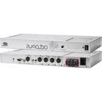


Brand : Phoenix Audio
Model : DRS-8 Mk2
Category : Receiver