
S-65HT - Home speaker DENON - Free user manual and instructions
Find the device manual for free S-65HT DENON in PDF.

| Brand | DENON |
| Model | S-65HT |
| Product type | 5.1 home cinema speaker system |
| Satellite speakers | 5 multi-way speakers (SC-A65) |
| Center speaker | 1 multi-way speaker (SC-C65) |
| Subwoofer | 1 active subwoofer (DSW-65) |
| Subwoofer power | Approximately 100 W (estimated) |
| Frequency response | 40 Hz - 20 kHz (estimated) |
| Impedance | 6 ohms (estimated) |
| Sensitivity | 86 dB (estimated) |
| Satellite dimensions (approx.) | 100 x 200 x 150 mm (estimated) |
| Satellite weight (approx.) | 1 kg each (estimated) |
| Center dimensions (approx.) | 400 x 150 x 100 mm (estimated) |
| Center weight (approx.) | 2 kg (estimated) |
| Subwoofer dimensions (approx.) | 300 x 400 x 400 mm (estimated) |
| Subwoofer weight (approx.) | 10 kg (estimated) |
| Power supply | Subwoofer: mains (cord included) |
| Cable length | Cord A: 10 m, Cord B: 3 m (RCA) |
| Safety | Leave 10 cm space around, avoid high temperatures, handle cord with care |
| Maintenance and cleaning | Clean with a dry cloth, avoid chemicals |
| Spare parts and repairability | Contact DENON customer service |
| Package contents | Satellites (5), center (1), subwoofer (1), bases, cables, non-slip pads, manual |
Frequently Asked Questions - S-65HT DENON
User questions about S-65HT DENON
0 question about this device. Answer the ones you know or ask your own.
Ask a new question about this device
Download the instructions for your Home speaker in PDF format for free! Find your manual S-65HT - DENON and take your electronic device back in hand. On this page are published all the documents necessary for the use of your device. S-65HT by DENON.
USER MANUAL S-65HT DENON
TO PREVENT FIRE OR SHOCK HAZARD, DO NOT EXPOSE THIS APPLIANCE TO RAIN OR MOISTURE.
"SERIAL NO.
PLEASE RECORD UNIT SERIAL NUMBER ATTACHED TO THE REAR OF THE CABINET FOR FUTURE REFERENCE"
CAUTION:
- The ventilation should not be impeded by covering the ventilation openings with items, such as newspapers, tablecloths, curtains, etc.
- No naked flame sources, such as lighted candles, should be placed on the apparatus.
- Please be care the environmental aspects of battery disposal.
- The apparatus shall not be exposed to dripping or splashing for use.
- No objects filled with liquids, such as vases, shall be placed on the apparatus.
CAUTION
RISK OF ELECTRIC SHOCK DO NOT OPEN

CAUTION:
TO REDUCE THE RISK OF ELECTRIC SHOCK, DO NOT REMOVE COVER (OR BACK). NO USER-SERVICEABLE PARTS INSIDE. REFER SERVICING TO QUALIFIED SERVICE PERSONNEL.

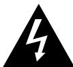
The lightning flash with arrowhead symbol, within an equilateral triangle, is intended to alert the user to the presence of uninsulated "dangerous voltage" within the product's enclosure that may be of sufficient magnitude to constitute a risk of electric shock to persons.

The exclamation point within an equilateral triangle is intended to alert the user to the presence of important operating and maintenance (servicing) instructions in the literature accompanying the appliance.
- DECLARATION OF CONFORMITY
We declare under our sole responsibility that this product, to which this declaration relates, is in conformity with the following standards:
EN60065, EN55013, EN55020, EN61000-3-2 and EN61000-3-3.
Following the provisions of 73/23/EEC, 89/336/EEC and 93/68/EEC Directive.
For heat dispersal, leave at least 10cm of space between the top, back and sides of this unit and the wall or other components.
Allow for sufficient heat dispersion when installed on a rack.
- Handle the power cord carefully.
Hold the plug when unplugging the cord.
* (For sets with ventilation holes)
- Do not obstruct the ventilation holes.
Die Belüftungsöffnungen)dürfen nicht verdeckt werden. - Ne pas obstruer les troughs d'airation.
Non coprite i fori di ventilazione. - No obstruya los orificios de ventilación.
- De ventilatieopengingenogensniet worden beblokkeerd.
- Do not let foreign objects in the set.
- Keine fremden Gegenstände in das Gerätkommenleen.
- Ne pas laisser des objets étrangers dans l'appareil.
- E' importante che nessun oggetto è inserto all'interno dell'unità.
- No deje objetos extraños dentro del equipo.
- Laat geen vreemde voorwerpen in dit apparaat vallen.

- Do not let insecticides, benzene, and thinner come in contact with the set.
- Lassen Sie das Gerät nicht mit Insektiziden, Benzin oder Verdünningsmitteln in Berührung kommt.
- Ne pasmettre en contact des insecticides,du benzene et un diluant avec l'appareil.
- Assicuratevvi che l'unità non venga in contatto con insetticidi, benzolo solventi.
- No permitted contacto de insecticidas, gasolina y diluyentes con el equipo.
- Laat geen insetkenverdelgende middelen, benzine of verfverdunner met dit apparaat inkontakt komen.

- Never disassemble or modify the set in any way.
Versuchen Sie niemals das Gerät auseinander zu erhmen oder auf jegliche Art zu verändern. - Ne jamais démonter ou modifier l'appareil d'une manière ou d'une autre.
- Non smontate mai, né modifiche l'unità in nessun modo.
- Nunca desarme o modifique el equipo de ninguna manera.
- Nooit dit apparaat demonteren of op andere wijze modifierten.
SAFETY INSTRUCTIONS
- Read Instructions - All the safety and operating instructions should be read before the product is operated.
- Retain Instructions - The safety and operating instructions should be retained for future reference.
- HeedWarnings - All warnings on the product and in the operating instructions should be adhered to.
- Follow Instructions - All operating and use instructions should be followed.
- Cleaning - Unplug this product from the wall outlet before cleaning. Do not use liquid cleaners or aerosol cleaners.
- Attachments - Do not use attachments not recommended by the product manufacturer as they may cause hazards.
- Water and Moisture - Do not use this product near water - for example, near a bath tub, wash bowl, kitchen sink, or laundry tub; in a wet basement; or near a swimming pool; and the like.
- Accessories - Do not place this product on an unstable cart, stand, tripod, bracket, or table. The product may fall, causing serious injury to a child or adult, and serious damage to the product. Use only with a cart, stand, tripod, bracket, or table recommended by the manufacturer, or sold with the product. Any mounting of the product should follow the manufacturer's instructions, and should use a
mounting accessory recommended by the manufacturer.
- A product and cart combination should be moved with care. Quick stops, excessive force, and uneven surfaces may cause the product and cart combination to overturn.

- Ventilation – Slots and openings in the cabinet are provided for ventilation and to ensure reliable operation of the product and to protect it from overheating, and these openings must not be blocked or covered. The openings should never be blocked by placing the product on a bed, sofa, rug, or other similar surface. This product should not be placed in a built-in installation such as a bookcase or rack unless proper ventilation is provided or the manufacturer's instructions have been adhered to.
- Power Sources - This product should be operated only from the type of power source indicated on the marking label. If you are not sure of the type of power supply to your home, consult your product dealer or local power company. For products intended to operate from battery power, or other sources, refer to the operating instructions.
- Grounding or Polarization - This product may be equipped with a polarized alternating-current line plug (a plug having one blade wider than the other). This plug will fit into the power outlet only one way. This is a safety feature. If you are unable to insert the plug fully into the outlet, try reversing the plug. If the plug should still fail to fit, contact your electrician to replace your obsolete outlet. Do not defeat the safety purpose of the polarized plug.
- Power-Cord Protection - Power-supply cords should be routed so that they are not likely to be walked on or pinched by items placed upon or against them, paying particular attention to cords at plugs, convenience receptacles, and the point where they exit from the product.
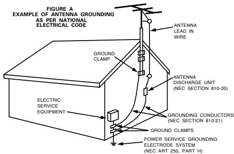
- Outdoor Antenna Grounding - If an outside antenna or cable system is connected to the product, be sure the antenna or cable system is grounded so as to provide some protection against voltage surges and built-up static charges. Article 810 of the National Electrical Code, ANSI/NFPA 70, provides information with regard to proper grounding of the mast and supporting structure, grounding of the lead-in wire to an antenna discharge unit, size of grounding conductors, location of antenna-discharge unit, connection to grounding electrodes, and requirements for the grounding electrode. See Figure A.
- Lightning - For added protection for this product during a lightning storm, or when it is left unattended and unused for long periods of time, unplug it from the wall outlet and disconnect the antenna or cable system. This will prevent damage to the product due to lightning and power-line surges.
- Power Lines - An outside antenna system should not be located in the vicinity of overhead power lines or other electric light or power circuits, or where it can fall into such power lines or circuits. When installing an outside antenna system, extreme care should be taken to keep from touching such power lines or circuits as contact with them might be fatal.
- Overloading - Do not overload wall outlets, extension cords, or integral convenience receptacles as this can result in a risk of fire or electric shock.
- Object and Liquid Entry - Never push objects of any kind into this product through openings as they may touch dangerous voltage points or short-out parts that could result in a fire or electric shock. Never spill liquid of any kind on the product.
- Servicing - Do not attempt to service this product yourself as opening or removing covers may expose you to dangerous voltage or other hazards. Refer all servicing to qualified service personnel.
- Damage Requiring Service – Unplug this product from the wall outlet and refer servicing to qualified service personnel under the following conditions:
a) When the power-supply cord or plug is damaged,
b) If liquid has been spilled, or objects have fallen into the product,
c) If the product has been exposed to rain or water,
d) If the product does not operate normally by following the operating instructions. Adjust only those controls that are covered by the operating instructions as an improper adjustment of other controls may result in damage and will often require extensive work by a qualified technician to restore the product to its normal operation,
e) If the product has been dropped or damaged in any way, and
f) When the product exhibits a distinct change in performance – this indicates a need for service.
- Replacement Parts - When replacement parts are required, be sure the service technician has used replacement parts specified by the manufacturer or have the same characteristics as the original part. Unauthorized substitutions may result in fire, electric shock, or other hazards.
- Safety Check - Upon completion of any service or repairs to this product, ask the service technician to perform safety checks to determine that the product is in proper operating condition.
- Wall or Ceiling Mounting - The product should be mounted to a wall or ceiling only as recommended by the manufacturer.
- Heat - The product should be situated away from heat sources such as radiators, heat registers, stoves, or other products (including amplifiers) that produce heat.
CONTENTS SYS-65HT
- Satellite speaker system (SC-A65) 5
- Center speaker system (SC-C65) 1
3.Active subwoofer (DSW-65) 1 - BASE 1
- Cord A (10 m) 6
- Cord B (3 m RCA PIN) 1
- Anti-slip pad (4 pcs. / 1 sheet) .5
- Operating instructions 1
- DENON Service network 1
INHALT SYS-65HT
- Satellite speaker system (SC-A65) 4
- Center speaker system (SC-C65) 1
3.Active subwoofer (DSW-65) 1 - BASE 1
5.Cord A (10 m) .5 - Cord B (3 m RCA PIN)
- Anti-slip pad (4 pcs./1 sheet) 4
- Operating instructions 1
- DENON Service network
INHALT SYS-55HT
CAUTIONS ON HANDLING
When installing, carefully examine the place and method of installation for safety.
When using a stand, brackets, etc., follow the instructions included with the stand or brackets and check for safety before installing and using. Denon will accept no responsibility for damages or accidents caused by the unit falling.
Cautions on Installation - Speaker System (SC-A65, SC-C65)
The quality of the sound produced from the speaker system is affected by the size and type (Japanese or Western) of the room, as well as by the method of installation. Consider the points listed below before installing the speaker system.
Note that placing the speaker system on the same stand or shelf as a record player may result in howling.
If there is a wall, glass door, etc., directly in front of or behind the speaker system, cover the wall or door with a thick curtain to prevent resonance and reflection.
The SC-A65 and SC-C65 speaker systems are of the low-leakage-flux type and can be used near televisions, but depending on the TV there may be color blotching on the picture. If this happens, turn off the TV's power, wait 15 to 30 minutes, then turn the TV's power back on. The TV's automatic degaussing circuit should reduce the blotching on the picture. If blotching persists, move the speaker further away.
The center speaker (SC-C65) is equipped with anti-slip pads upon shipment from the factory. If necessary, however, also apply the included anti-slip pads (cork, approximately 1 mm thick).
When placing the satellite speaker system (SC-A65) on a stand, etc., stick the included anti-slip pads (cork, approximately 1 mm thick) at the four corners of the bottom surface. (Refer to the illustration below.)
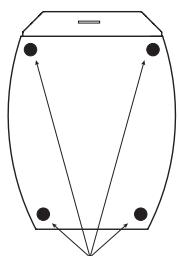
[ Satellite speaker system (illustration of bottom of SC-A65)]
Anti-slip pads (1 mm thick)
[Bottom]
Speaker stand/speaker bracket mount screw holes
[Rear]
■ When mounting the satellite speaker system (SC-A65) on a stand or bracket, M5 nuts are inserted into the bottom of the satellite speaker system (SC-A65) at intervals of 60~mm . When mounting, following the instructions in the manual included with the speaker stand or ceiling mount bracket, and be sure to install properly and securely.
■ When the satellite speaker system (SC-A65) is mounted on a ceiling mount bracket, it is turned upside down due to the installation angle. The Denon mark is also turned upside down, so detach the speaker net and reattach it in the opposite direction.
CAUTION:
- To ensure safety, do not place any objects on top or lean objects against the speaker system.
- The speaker may topple down or fall if force is applied to the sides. Be particularly careful to avoid this, as this could cause injury or other serious accidents.
WARNING:
- When installing the speaker systems on the ceiling or wall, to ensure safety, have specialists do the installation work.
- Be sure to fasten the speaker cords to a wall, etc., to prevent people from tripping over them or otherwise pulling on them accidentally, causing the speaker systems to fall.
- Be sure to check for safety after installing the speaker systems. Afterwards, perform safety inspections at regular intervals to be sure there is no danger that the speaker systems will fall. Denon will accept no responsibility for damages or accidents caused by inappropriate choice of the place of installation or improper installation procedures.
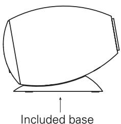
Speaker system (SC-C65)
- The included base can be used to set the speaker systems (SC-C65) at one of three angles: level, slanting upward or slanting down ward.
To set the speaker system level
Use the included base and set as shown on the diagram below.
In this case, do not use the four included anti-slip pads (pieces of cork 1 mm thick).
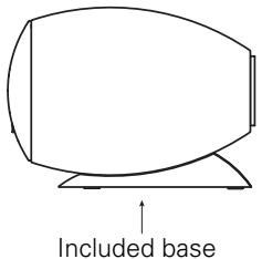
[Speaker system (SC-C65) side view]
To set the speaker system at an angle slanting upwards
Use the included base and set as shown on the diagram below.
In this case, do not use the four included anti-slip pads (pieces of cork 1 mm thick).
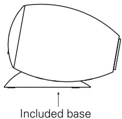
[Speaker system (SC-C65) side view]
To set the speaker system at an angle slanting down wards
Use the included base and set as shown on the diagram below.
In this case, do not use the four included anti-slip pads (pieces of cork 1 mm thick).
[Speaker system (SC-C65) side view]
CAUTION:
- Use the included base and set in a firm stable place.
- If the speaker system is set in an unstable place, it could tip over or fall, possibly resulting in serious accidents.
CAUTIONS ON HANDLING (continued)
Other Cautions (SC-A65, SC-C65)
Note that color blotching may occur on a TV, etc., due to interaction with the speaker system if there is a magnet or an object generating magnetic force nearby.
Examples: (a) When there are magnets on the door of the rack, stand, etc.
(b) When a health device, etc., equipped with magnets is placed nearby.
(c) When toys or other objects using magnets are placed nearby.
Note that the illustrations in this instructions may differ from the actual set for explanation purposes.
■ Be sure to keep the operating instructions.
After reading these operating instructions, store them in a safe place. We also recommend filling in the necessary items on the back cover.
Cautions on Installation - Active subwoofer (DSW-65)
Note that placing the active subwoofer on the same stand or shelf as a record player may result in howling.
The DSW-65 active subwoofer is a Lowleakage-Flux type speaker system and can be used near televisions, but depending on the TV there may be color blotching on the picture. If this happens, turn off the TV's power, move the TV and subwoofer a little apart, wait 15 to 30 minutes, then turn the TV's power back on. The TV's automatic degaussing circuit should reduce the blotching on the picture. If blotching persists, move the subwoofer and TV further away from each other.
Install on a firm, flat floor to prevent accidents due to toppling down.
■ Do not place a record player, CD player or other AV device on top of the active subwoofer.
Other Cautions - Active subwoofer (DSW-65)
The built-in amplifier of the active subwoofer (DSW-65) includes a mating circuit. The output signal is strongly attenuated for several seconds after the power is turned on. If the volume is adjusted during this time, the output may be extremely high when the mating circuit is deactivated. Be sure to wait for the mating circuit to be deactivated before adjusting the volume.
Note that color blotching may occur on a TV, etc., due to interaction with the subwoofer if there is a magnet or an object generating magnetic force nearby.
Examples: (a) When there are magnets on the door of the rack, stand, etc.
(b) When a health device, etc., equipped with magnets is placed nearby.
(c) When toys or other objects using magnets are placed nearby.
Note that the illustrations in this instructions may differ from the actual set for explanation purposes.
■ Be sure to keep the operating instructions.
After reading these operating instructions, store them in a safe place. We also recommend filling in the necessary items on the back cover.
WARNING:
- Be sure to fasten the power cord to a wall, etc., to prevent people from tripping over it or otherwise pulling on it accidentally, causing the subwoofer to fall.
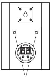
Active subwoofer (DSW-65) rear panel
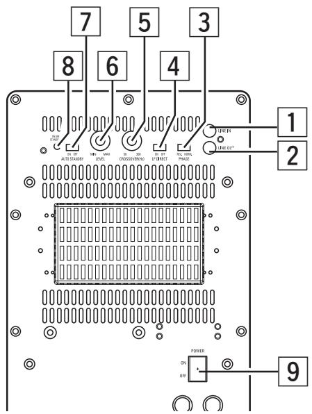
Line input connector (LINE IN)
- Connect this to the AV amplifier's pre-out connector ("SUBWOOFER", "MONO OUT", etc.) using the included connection cord (3-meter RCA pin cord).
2 Line output connector (LINE OUT)
- The signal input to the line input connector is output as such from here in parallel.
- When using two active subwoofoers, connect the other active subwoofer's line input connector to this connector.
3 Phase selector switch (PHASE)
- This switches the phase of the output signal with respect to the input signal.
- Normally use the active subwoofer with this switch set at the "NORM." position. If the continuity between the sound of the active subwoofer and the left and right speakers seems unnatural, try switching to the "REV." position, and set the switch to the position in which the sound is most natural.
4 LF direct switch (LF DIRECT)
- When using the active subwoofer connected to a Dolby Digital or dts-compatible AV amplifier, if this function is turned on the signals bypass the active subwoofer's crossover and volume adjustment circuits, resulting in purer, higher quality sound. Note that when this is done the crossover adjustment control (5) and volume adjustment control (6) will no longer function.
5 Crossover adjustment control (CROSSOVER)
- This control only functions when the LF DIRECT switch 4 is set to the "OFF" position.
- This control sets the upper limit of the frequencies reproduced by the active subwoofer.
- Setting criteria
50Hz : For left/right speakers with diameters of20 cm or greater
100Hz : For left/right speakers with diametersbetween 10 and 25 cm
200Hz : For left/right speakers with diameters of12 cm or less
- When using a Dolby Digital or dts-compatible AV amplifier, we recommend turning the LF DIRECT switch (4) to the "ON" position and not using this function.
※ “Dolby” is a trademark of the Dolby Laboratories Licensing Corporation.
※“dtts” is a trademark of Digital Theater Systems.
PART NAMES AND FUNCTIONS (continued)
About the AV amplifier's crossover frequency selection
The crossover frequency of the satellite speaker/center speaker and the active subwoofer (the boundary between the frequency range produced by the active subwoofer and the other speakers) is set on the connected AV amplifier, and is usually fixed at between 80 and 120kHz .
With some amplifiers, however, including the Denon AV amplifier, this frequency can be selected. When using this type of amplifier, the crossover frequency can be selected to suit your tastes.
When using the DSW-65 active subwoofer with this type of amplifier, a richer sound can be achieved by setting the crossover frequency to around 150Hz . Adjust the crossover frequency to suit your tastes. For instructions on switching, refer to your amplifier's operating instructions.
When connecting to a Dolby Digital or dtsc-compatible AV amplifier, whether one on which the crossover frequency is fixed or one on which it can be adjusted, we recommend setting the LF DIRECT switch of the active subwoofer (DSW-65) to the "ON" position.
6 Volume adjustment control (LEVEL)
- This control only functions when the LF DIRECT switch (4) is set to the "OFF" position.
- Use this control to adjust the volume of the active subwoofer.
- When turned clockwise (O) from the center position, the volume of the active subwoofer increases, and when turned counterclockwise (O), the volume decreases. Set to the desired position.
- For some signals, a very soft sound will be produced even when the volume adjustment control("LEVEL") is turned fully counterclockwise (O) and set to the minimum ("MIN"). This is not a malfunction.
If this should happen, connect the cord connected to the set's LINE IN connector to an output connector (SUB WOOFER PRE OUT, MONO OUT, etc.) for which the signals pass through the master volume circuitry of the AV surround amplifier, etc., before being output.
Use the set's volume adjustment control ("LEVEL") to adjust the volume difference with the speakers other than the super woofer (front, center, surround, etc.), and adjust the overall volume using the master volume control on the AV surround amplifier, etc.
7 Auto standby selector switch (AUTO STANDBY)
ON : The auto standby function is activated
OFF : The auto standby function is deactivated
Auto Standby Function
- The amplifier is automatically set to the standby mode if no signal is input for 5 to 11 minutes, thereby saving electricity.
The power turns on immediately when a signal is input.
8 Status indicator
- The two-colored LED indicates the active subwoofer's operating status, as follows:
Power "ON". Lights green
Auto power off (standby mode).Lights red
Power "OFF" LED off
Protective circuit activated.........Flashing red
9 Power switch (POWER)
- The power turns on when this switch is set to the "ON" position.
- Several seconds are required for the set to begin operating. This is because the set includes a built-in muting circuit to prevent noise when the power switch is turned on and off.
- When set to the "OFF" position, the power turns off.
CONNECTIONS
CAUTION:
- Do not plug the AC power cord into an AC power outlet until all connections have been completed.
- Check the left and right channels and be sure to interconnect them properly, L (left) to L, R (right) to R.
- Plug the AC power cord in securely. An insecure connection could cause noise.
- Note that clamping pin-plug cords and power cords together or running pin-plug cords near the power transformer could result in humming or noise.
- Check the polarities of the speakers and amplifier and be sure to interconnect properly. Connect the red terminal on the speaker to the "+" speaker terminal on the amplifier, the black terminal on the speaker to the "-" speaker terminal on the amplifier.
(1) Connecting the line input connector (LINE IN)
- Connect this to the pre-out connector for the active subwoofer on the AV amplifier ("SUBWOOFER PREOUT", "MONO OUT", etc.) using the included connection cord (3-meter RCA pin cord).

CAUTION:
- If this connector is connected to the pre-out connector for the surround center channel of a stereo amplifier or AV surround amplifier, only the center channel's bass sound will be produced, so the overall bass sound will be insufficient.
CONNECTIONS (continued)
(2) Connecting the speaker terminals
- Read the amplifier's operating instructions carefully before connecting, and be sure to use properly.
- When connecting the equipment or changing the connections, be sure to turn the equipment's power switches off and unplug the power plugs from the AC power outlets.
Connecting the speaker terminals
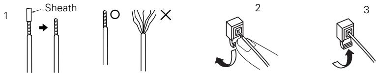
- Peel off the sheath from the tip of the connection cord, then firmly twist the wires by hand so that they do not stick out and cause short-circuits.
- Press and lower the lever, and insert the cord's core wire into the hole.
- Release the lever.
Gently pull on the connection cord to check that it is firmly connected.
To “-” side on amplifier (silver colored core wire)
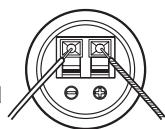
The red side is the "+" side, the black side the "- " side.
To "+" side on amplifier (copper colored core wire)
NOTE: Make sure the core wires do not touch each other.
Once the connections are completely, gently pull on the speaker cords to make sure they are securely connected.
CAUTION:
- Be careful to interconnect the positive (^ + ^ , red) and negative (一 ^ ) black) sides and the left and right speakers properly.
- Connect the side of the included connection cord with the copper colored core wires to the red speaker terminal.
- To prevent circuit problems, never short-circuit copper and silver colored core wires or the left and right cords.

When installing, carefully examine the place and method of installation for safety.
When using a stand, brackets, etc., follow the instructions included with the stand or brackets and check for safety before installing and using. Denon will accept no responsibility for damages or accidents caused by the unit falling.
USING THE ACTIVE SUBWOOFER (DSW-65)
-
Set the power switch to the "ON" position.
-
When the unit's AC power cord is plugged into a switched AC outlet on the amplifier, if the power switch is left at the "ON" position, the unit's power turns on and off automatically when the amplifier's power is turned on and off.
-
If the AC power cord is not plugged into a switched AC outlet on the amplifier, set the unit's power switch to the "ON" position after turning on the amplifier's power. When turning the power off, set the unit's power switch to the "OFF" position before turning off the amplifier's power.
-
Adjust the volume using the volume adjustment control.
※ For details, see "PART NAMES AND FUNCTIONS".
REMOVING THE SPEAKER NET (SC-A65, SC-C65)
- The net on the front of the speaker systems (SC-A65, SC-C65) can be removed.
- To remove, grasp both sides of the net and pull forward.
- To mount, line up the holes in the four corners of the speaker net with the projecting pieces in the four corners of the cabinet and press in.
TROUBLESHOOTING
Troubleshooting
Are the connections proper?
■ Are you operating correctly as describe in the operating instructions?
Are the amplifier and player(s) operating properly?
If the set does not operate properly, check the items on the table below. If this does not solve the problem, the set may be out of order. Turn off the power, unplug the AC power cord from the AC power outlet, then contact your store of purchase. If your store of purchase cannot help you, please contact your Denon nearest authorized service network.
| Symptom | Cause | Remedy |
| Active subwoofer (DSW-65):LED does not light and no sound is produced when power is turned on. | • AC power plug is not securely connected. | • Check the connection of the AC power plug. |
| Active subwoofer (DSW-65):LED lights but no sound is produced. | • Cords are not securely connected.• Volume adjustment control is turned all the way down. | • Connect securely.• Turn the control and set it to the desired position. |
| Active subwoofer (DSW-65):LED flashes and no sound is produced. | • Protective circuit has been activated due to excess input or rise in temperature. | • Set the power switch to the “OFF” position, wait at least 1 minute, then set the power switch back to the “ON” position. If the problem persists, unplug the AC power cord from the AC power outlet and contact your store of purchase. |
| Active subwoofer (DSW-65):Sound is distorted. | • Volume level is too high.• Sound is being distorted on connected amplifier. | • Turn the volume adjustment control counterclockwise to lower the volume.• Do not amplify the bass sound on the amplifier. (Lower the amplifier’s bass adjustment control or volume.) |
| Active subwoofer (DSW-65):Oscillation (loud continuous sound produced). | • Volume of active subwoofer or amplifier set too high. | • Lower the volume of the active subwoofer or amplifier. |
For improvement purposes, specifications and design are subject to change without notice.
SPECIFICATION
Satellite speaker system (SC-A65)
| Type: | 2-way, 2-speakers |
| Closed box / Low-leakage-flux | |
| Speakers: | 9 cm cone bass-mid x 1 |
| 2.5 cm super-high range x 1 | |
| Input impedance: | 6 Ω/ohms |
| Max. input: | 40 watts (IEC) |
| 100 watts (PEAK) | |
| Crossover frequency: | 6 kHz |
| Frequency range: | 60 Hz ~ 22 kHz |
| Dimensions: | 130(W) x 180 (H) x 171 (D) mm |
| Mass: | 1.2 kg |
Center speaker system (SC-C65)
| Type: | 2-way, 3-speakers |
| Closed box / Low-leakage-flux | |
| Speakers: | 9 cm cone bass-mid x 2 |
| 2.5 cm super-high range x 1 | |
| Input impedance: | 6 Ω/ohms |
| Max. input: | 40 watts (IEC) |
| 100 watts (PEAK) | |
| Crossover frequency: | 6 kHz |
| Frequency range: | 60 Hz ~ 22 kHz |
| Dimensions: | 290 (W) x 130 (H) x 192 (D) mm |
| Mass: | 1.8 kg |
Active subwoofer (DSW-65)
| Type: | 1-way, 1-speaker |
| Reflex box / Low-leakage-flux | |
| Built-in amplifier | |
| Speaker: | 25 cm cone woofer x 1 |
| Speaker impedance: | 4 Ω/ohms |
| Frequency range: | 25 Hz ~ 200 Hz |
| (LF Direct / Off) | |
| Rated output power: | 100 watts |
| (4 Ω/ohms load, 55Hz, T.H.D. 0.7%) | |
| Input impedance: | 22 kΩ/kohms |
| Crossover frequency: | 50 Hz ~ 200 Hz (Variable) |
| (LF Direct / Off) | |
| Power supply: | 120V / 60Hz (North America) |
| 230V / 50Hz (Europe) | |
| Power consumption: | 55 watts (UL / IEC) |
| < 1 watt (Standby) | |
| Dimensions: | 310(W) x 351(H) x 436(D) mm |
| (including base) | |
| Mass: | 12.0 kg (including base) |
- For improvement purpose, specifications and design are subject to change without notice.
- CAUTION:
- CAUTION
- - DECLARATION OF CONFORMITY
- SAFETY INSTRUCTIONS
- CONTENTS SYS-65HT
- INHALT SYS-65HT
- INHALT SYS-55HT
- CAUTIONS ON HANDLING
- When installing, carefully examine the place and method of installation for safety.
- Cautions on Installation - Speaker System (SC-A65, SC-C65)
- The quality of the sound produced from the speaker system is affected by the size and type (Japanese or Western) of the room, as well as by the method of installation. Consider the points listed below before installing the speaker system.
- WARNING:
- Speaker system (SC-C65)
- To set the speaker system level
- To set the speaker system at an angle slanting upwards
- To set the speaker system at an angle slanting down wards
- CAUTIONS ON HANDLING (continued)
- Other Cautions (SC-A65, SC-C65)
- Cautions on Installation - Active subwoofer (DSW-65)
- Other Cautions - Active subwoofer (DSW-65)
- Active subwoofer (DSW-65) rear panel
- Line input connector (LINE IN)
- Line output connector (LINE OUT)
- Phase selector switch (PHASE)
- LF direct switch (LF DIRECT)
- Crossover adjustment control (CROSSOVER)
- PART NAMES AND FUNCTIONS (continued)
- About the AV amplifier's crossover frequency selection
- Volume adjustment control (LEVEL)
- Auto standby selector switch (AUTO STANDBY)
- Auto Standby Function
- Status indicator
- Power switch (POWER)
- CONNECTIONS
- Connecting the line input connector (LINE IN)
- CONNECTIONS (continued)
- Connecting the speaker terminals
- Connecting the speaker terminals
- Once the connections are completely, gently pull on the speaker cords to make sure they are securely connected.
- USING THE ACTIVE SUBWOOFER (DSW-65)
- REMOVING THE SPEAKER NET (SC-A65, SC-C65)
- TROUBLESHOOTING
- Are the connections proper?
- ■ Are you operating correctly as describe in the operating instructions?
- Are the amplifier and player(s) operating properly?
- SPECIFICATION
- Satellite speaker system (SC-A65)
- Center speaker system (SC-C65)
- Active subwoofer (DSW-65)
Brand : DENON
Model : S-65HT
Category : Home speaker